JP5411458B2 - 3D ultrasonic transmission beam forming - Google Patents
3D ultrasonic transmission beam forming Download PDFInfo
- Publication number
- JP5411458B2 JP5411458B2 JP2008159813A JP2008159813A JP5411458B2 JP 5411458 B2 JP5411458 B2 JP 5411458B2 JP 2008159813 A JP2008159813 A JP 2008159813A JP 2008159813 A JP2008159813 A JP 2008159813A JP 5411458 B2 JP5411458 B2 JP 5411458B2
- Authority
- JP
- Japan
- Prior art keywords
- sub
- aperture
- transducer elements
- transducer
- transmit
- Prior art date
- Legal status (The legal status is an assumption and is not a legal conclusion. Google has not performed a legal analysis and makes no representation as to the accuracy of the status listed.)
- Active
Links
- 230000005540 biological transmission Effects 0.000 title claims description 104
- 238000002604 ultrasonography Methods 0.000 claims description 61
- 239000000523 sample Substances 0.000 claims description 42
- 238000013507 mapping Methods 0.000 claims description 5
- 238000010586 diagram Methods 0.000 description 15
- 239000011159 matrix material Substances 0.000 description 14
- 238000000034 method Methods 0.000 description 10
- 239000013598 vector Substances 0.000 description 7
- 230000001934 delay Effects 0.000 description 6
- XUIMIQQOPSSXEZ-UHFFFAOYSA-N Silicon Chemical compound [Si] XUIMIQQOPSSXEZ-UHFFFAOYSA-N 0.000 description 5
- 230000014509 gene expression Effects 0.000 description 5
- 229910052710 silicon Inorganic materials 0.000 description 5
- 239000010703 silicon Substances 0.000 description 5
- 230000006870 function Effects 0.000 description 2
- 239000000463 material Substances 0.000 description 2
- 239000000203 mixture Substances 0.000 description 2
- 238000012545 processing Methods 0.000 description 2
- 238000012285 ultrasound imaging Methods 0.000 description 2
- 208000008312 Tooth Loss Diseases 0.000 description 1
- 238000003491 array Methods 0.000 description 1
- 230000002457 bidirectional effect Effects 0.000 description 1
- 210000000601 blood cell Anatomy 0.000 description 1
- 238000004891 communication Methods 0.000 description 1
- 230000001419 dependent effect Effects 0.000 description 1
- 238000002059 diagnostic imaging Methods 0.000 description 1
- 238000009826 distribution Methods 0.000 description 1
- 230000009977 dual effect Effects 0.000 description 1
- 230000000694 effects Effects 0.000 description 1
- 230000007717 exclusion Effects 0.000 description 1
- 230000020169 heat generation Effects 0.000 description 1
- 238000007689 inspection Methods 0.000 description 1
- 238000002372 labelling Methods 0.000 description 1
- 238000004519 manufacturing process Methods 0.000 description 1
- 238000012986 modification Methods 0.000 description 1
- 230000004048 modification Effects 0.000 description 1
- 210000003205 muscle Anatomy 0.000 description 1
- 238000005457 optimization Methods 0.000 description 1
- 238000005192 partition Methods 0.000 description 1
- 238000013139 quantization Methods 0.000 description 1
- 230000011218 segmentation Effects 0.000 description 1
- 238000000926 separation method Methods 0.000 description 1
- 238000003860 storage Methods 0.000 description 1
Images


Classifications
-
- G—PHYSICS
- G03—PHOTOGRAPHY; CINEMATOGRAPHY; ANALOGOUS TECHNIQUES USING WAVES OTHER THAN OPTICAL WAVES; ELECTROGRAPHY; HOLOGRAPHY
- G03B—APPARATUS OR ARRANGEMENTS FOR TAKING PHOTOGRAPHS OR FOR PROJECTING OR VIEWING THEM; APPARATUS OR ARRANGEMENTS EMPLOYING ANALOGOUS TECHNIQUES USING WAVES OTHER THAN OPTICAL WAVES; ACCESSORIES THEREFOR
- G03B42/00—Obtaining records using waves other than optical waves; Visualisation of such records by using optical means
- G03B42/06—Obtaining records using waves other than optical waves; Visualisation of such records by using optical means using ultrasonic, sonic or infrasonic waves
-
- A—HUMAN NECESSITIES
- A61—MEDICAL OR VETERINARY SCIENCE; HYGIENE
- A61B—DIAGNOSIS; SURGERY; IDENTIFICATION
- A61B8/00—Diagnosis using ultrasonic, sonic or infrasonic waves
- A61B8/44—Constructional features of the ultrasonic, sonic or infrasonic diagnostic device
- A61B8/4444—Constructional features of the ultrasonic, sonic or infrasonic diagnostic device related to the probe
- A61B8/4461—Features of the scanning mechanism, e.g. for moving the transducer within the housing of the probe
-
- A—HUMAN NECESSITIES
- A61—MEDICAL OR VETERINARY SCIENCE; HYGIENE
- A61B—DIAGNOSIS; SURGERY; IDENTIFICATION
- A61B8/00—Diagnosis using ultrasonic, sonic or infrasonic waves
- A61B8/44—Constructional features of the ultrasonic, sonic or infrasonic diagnostic device
- A61B8/4483—Constructional features of the ultrasonic, sonic or infrasonic diagnostic device characterised by features of the ultrasound transducer
-
- G—PHYSICS
- G01—MEASURING; TESTING
- G01S—RADIO DIRECTION-FINDING; RADIO NAVIGATION; DETERMINING DISTANCE OR VELOCITY BY USE OF RADIO WAVES; LOCATING OR PRESENCE-DETECTING BY USE OF THE REFLECTION OR RERADIATION OF RADIO WAVES; ANALOGOUS ARRANGEMENTS USING OTHER WAVES
- G01S15/00—Systems using the reflection or reradiation of acoustic waves, e.g. sonar systems
- G01S15/88—Sonar systems specially adapted for specific applications
- G01S15/89—Sonar systems specially adapted for specific applications for mapping or imaging
- G01S15/8906—Short-range imaging systems; Acoustic microscope systems using pulse-echo techniques
- G01S15/8909—Short-range imaging systems; Acoustic microscope systems using pulse-echo techniques using a static transducer configuration
- G01S15/8915—Short-range imaging systems; Acoustic microscope systems using pulse-echo techniques using a static transducer configuration using a transducer array
- G01S15/8925—Short-range imaging systems; Acoustic microscope systems using pulse-echo techniques using a static transducer configuration using a transducer array the array being a two-dimensional transducer configuration, i.e. matrix or orthogonal linear arrays
-
- G—PHYSICS
- G01—MEASURING; TESTING
- G01S—RADIO DIRECTION-FINDING; RADIO NAVIGATION; DETERMINING DISTANCE OR VELOCITY BY USE OF RADIO WAVES; LOCATING OR PRESENCE-DETECTING BY USE OF THE REFLECTION OR RERADIATION OF RADIO WAVES; ANALOGOUS ARRANGEMENTS USING OTHER WAVES
- G01S15/00—Systems using the reflection or reradiation of acoustic waves, e.g. sonar systems
- G01S15/88—Sonar systems specially adapted for specific applications
- G01S15/89—Sonar systems specially adapted for specific applications for mapping or imaging
- G01S15/8906—Short-range imaging systems; Acoustic microscope systems using pulse-echo techniques
- G01S15/8909—Short-range imaging systems; Acoustic microscope systems using pulse-echo techniques using a static transducer configuration
- G01S15/8915—Short-range imaging systems; Acoustic microscope systems using pulse-echo techniques using a static transducer configuration using a transducer array
- G01S15/8927—Short-range imaging systems; Acoustic microscope systems using pulse-echo techniques using a static transducer configuration using a transducer array using simultaneously or sequentially two or more subarrays or subapertures
-
- A—HUMAN NECESSITIES
- A61—MEDICAL OR VETERINARY SCIENCE; HYGIENE
- A61B—DIAGNOSIS; SURGERY; IDENTIFICATION
- A61B8/00—Diagnosis using ultrasonic, sonic or infrasonic waves
- A61B8/44—Constructional features of the ultrasonic, sonic or infrasonic diagnostic device
- A61B8/4483—Constructional features of the ultrasonic, sonic or infrasonic diagnostic device characterised by features of the ultrasound transducer
- A61B8/4488—Constructional features of the ultrasonic, sonic or infrasonic diagnostic device characterised by features of the ultrasound transducer the transducer being a phased array
-
- A—HUMAN NECESSITIES
- A61—MEDICAL OR VETERINARY SCIENCE; HYGIENE
- A61B—DIAGNOSIS; SURGERY; IDENTIFICATION
- A61B8/00—Diagnosis using ultrasonic, sonic or infrasonic waves
- A61B8/44—Constructional features of the ultrasonic, sonic or infrasonic diagnostic device
- A61B8/4483—Constructional features of the ultrasonic, sonic or infrasonic diagnostic device characterised by features of the ultrasound transducer
- A61B8/4494—Constructional features of the ultrasonic, sonic or infrasonic diagnostic device characterised by features of the ultrasound transducer characterised by the arrangement of the transducer elements
-
- A—HUMAN NECESSITIES
- A61—MEDICAL OR VETERINARY SCIENCE; HYGIENE
- A61B—DIAGNOSIS; SURGERY; IDENTIFICATION
- A61B8/00—Diagnosis using ultrasonic, sonic or infrasonic waves
- A61B8/48—Diagnostic techniques
- A61B8/483—Diagnostic techniques involving the acquisition of a 3D volume of data
-
- B—PERFORMING OPERATIONS; TRANSPORTING
- B06—GENERATING OR TRANSMITTING MECHANICAL VIBRATIONS IN GENERAL
- B06B—METHODS OR APPARATUS FOR GENERATING OR TRANSMITTING MECHANICAL VIBRATIONS OF INFRASONIC, SONIC, OR ULTRASONIC FREQUENCY, e.g. FOR PERFORMING MECHANICAL WORK IN GENERAL
- B06B2201/00—Indexing scheme associated with B06B1/0207 for details covered by B06B1/0207 but not provided for in any of its subgroups
- B06B2201/70—Specific application
- B06B2201/76—Medical, dental
Description
本発明は、全般的には超音波医用撮像システムに関し、より具体的には、超音波信号の送信のための超音波探触子の複数のトランスジューサ素子の非重複サブアパーチャへの区分けに関する。 The present invention relates generally to ultrasound medical imaging systems, and more specifically to the segmentation of a plurality of transducer elements of an ultrasound probe for transmission of ultrasound signals into non-overlapping sub-apertures.
超音波システムの2つの主構成要素は超音波探触子とビーム形成器である。ビーム形成器は画像データの収集のために探触子により送信されかつ受信される超音波エネルギーを焦点合わせ及びステアリングしてあり、これがディスプレイ上に解剖学的コンテンツからなる画像を作成する1つの工程となっている。3次元(3D)超音波撮像は、トランスジューサ素子からなる2次元(2D)マトリックスアレイを有する探触子を用いて実施されることがある。多くのシステムでは、この構成要素は送信動作と受信動作の両方において用いられる。目下のシステムでは、トランスジューサ素子のこうしたデュアル動作をシステム内の送信回路と受信回路の間での多重化によって実現している。探触子内の各チャンネルは1本のケーブルを用いてシステムに接続されており、また各チャンネルが送信動作と受信動作の両者に関して使用されることがある。 The two main components of an ultrasound system are an ultrasound probe and a beamformer. The beamformer has focused and steered ultrasound energy transmitted and received by the probe for the collection of image data, one step of creating an image of anatomical content on the display It has become. Three-dimensional (3D) ultrasound imaging may be performed using a probe having a two-dimensional (2D) matrix array of transducer elements. In many systems, this component is used in both transmit and receive operations. In the current system, this dual operation of the transducer elements is achieved by multiplexing between the transmitter and receiver circuits in the system. Each channel in the probe is connected to the system using a single cable, and each channel may be used for both transmission and reception operations.
トランスジューサ素子は、トランスジューサ素子の部分組を互いにグループ分けすることによって送信動作と受信動作の両方に関して複数のサブアパーチャ(または、サブアレイ)に分割できる2Dアレイの形に配列させるのが一般的である。例えば各アパーチャは少なくとも1つの音響トランスジューサ素子を含むことがある。サブアパーチャのグループ分けは送信と受信に関して異ならせることがある。送信及び受信に関するサブアパーチャのレイアウト及び実現形態は画質に影響を及ぼす。探触子のうちの幾つかはその内部に配置させた送信器を利用しているが、この構成は大量の熱を発生させる可能性がある。したがって、比較的少ない数のシステムチャンネル(例えば、概ね170個のシステムチャンネル)によって多数の素子(例えば、概ね2600個の素子)を備えたアレイを駆動できるような2Dアレイ探触子に関する送信ソリューションを提供することが望ましい。 The transducer elements are typically arranged in a 2D array that can be divided into multiple sub-apertures (or sub-arrays) for both transmit and receive operations by grouping a subset of transducer elements together. For example, each aperture may include at least one acoustic transducer element. The sub-aperture groupings may differ for transmission and reception. The layout and implementation of the sub-aperture for transmission and reception affects the image quality. Some of the probes utilize transmitters located within them, but this configuration can generate a large amount of heat. Thus, a transmission solution for a 2D array probe that can drive an array with a large number of elements (eg, approximately 2600 elements) by a relatively small number of system channels (eg, approximately 170 system channels). It is desirable to provide.
したがって、上で検討した制限を伴わずにアパーチャの下位グループ分けを向上させた3D超音波撮像のための改良型の2Dアレイ送信ビーム形成に対する要求が存在する。 Accordingly, there is a need for improved 2D array transmit beamforming for 3D ultrasound imaging with improved aperture sub-grouping without the limitations discussed above.
一実施形態では、超音波システムは、超音波信号を受信するように構成された複数の受信素子を有するアパーチャを形成するトランスジューサ素子からなる2次元(2D)アレイを含んだ探触子を備える。これらのトランスジューサ素子は、アパーチャ内部の既定群のトランスジューサ素子と相互接続されるように構成させた少なくとも1つの送信サブアパーチャを形成する。送信器は送信電気信号を発生させており、また少なくとも1つの送信サブアパーチャプロセッサ(tx SAP)は既定群のトランスジューサ素子内部のトランスジューサ素子をビームステアリング方向に基づいた送信構成で送信器にマッピングしている。 In one embodiment, an ultrasound system includes a probe that includes a two-dimensional (2D) array of transducer elements that form an aperture having a plurality of receiving elements configured to receive ultrasound signals. The transducer elements form at least one transmit sub-aperture configured to be interconnected with a predetermined group of transducer elements within the aperture. The transmitter generates a transmit electrical signal, and at least one transmit sub-aperture processor (tx SAP) maps the transducer elements within a predetermined group of transducer elements to the transmitter in a transmit configuration based on the beam steering direction. Yes.
別の実施形態では、2Dアレイ状のトランスジューサ素子を用いて超音波信号を送信するための方法は、超音波送信信号を送信するためにある既定群のトランスジューサ素子を備えた少なくとも1つの送信サブアパーチャ並びに超音波受信信号を受け取るための少なくとも2つの受信サブアパーチャを形成する工程を含む。この少なくとも1つの送信サブアパーチャ及び少なくとも2つの受信サブアパーチャは事前決定のシステムチャンネル群に関連付けされている。既定群のトランスジューサ素子の内部のトランスジューサ素子のそれぞれに対して遅延が計算されており、該遅延はトランスジューサ素子及び送信動作に関連付けされたステアリング角に少なくとも基づいている。既定群のトランスジューサ素子内のトランスジューサ素子の少なくとも一部分は、トランスジューサ素子に関連付けされた遅延に少なくとも基づいて事前決定のシステムチャンネル群に接続されている。 In another embodiment, a method for transmitting an ultrasound signal using a 2D array of transducer elements includes at least one transmission sub-aperture with a predetermined group of transducer elements for transmitting ultrasound transmission signals. As well as forming at least two receive sub-apertures for receiving the ultrasound received signal. The at least one transmit sub-aperture and at least two receive sub-apertures are associated with a predetermined set of system channels. A delay is calculated for each of the transducer elements within the predetermined group of transducer elements, the delay being based at least on the steering angle associated with the transducer element and the transmission operation. At least a portion of the transducer elements within the predetermined group of transducer elements are connected to a predetermined system channel group based at least on a delay associated with the transducer element.
さらに別の実施形態では、超音波システムは超音波信号を受信するように構成された複数の受信素子を有するアパーチャを形成する2Dアレイ状のトランスジューサ素子を含んだ探触子を備える。少なくとも1つの構成可能交点スイッチは第1及び第2の側を有すると共に、超音波信号を送信するように構成された送信サブアパーチャを形成する既定群のトランスジューサ素子と第1の側において相互接続されている。システムチャンネルは、少なくとも送信信号を伝達するように構成されると共に、少なくとも1つの構成可能交点スイッチと第2の側で相互接続している。この少なくとも1つの構成可能交点スイッチはさらに、既定群のトランスジューサ素子内のトランスジューサ素子の各々に関連付けされた少なくとも1つのスイッチを備えると共に、この少なくとも1つの構成可能交点スイッチによってトランスジューサ素子のうちの少なくとも1つをシステムチャンネルの1つと接続させている。サブアパーチャプロセッサ(SAP)制御器は、既定群のトランスジューサ素子内部のトランスジューサ素子の各々をシステムチャンネルに対して送信信号に関連付けされた遅延に基づいた送信構成でマッピングするために少なくとも1つの構成可能交点スイッチを制御するように構成されている。 In yet another embodiment, an ultrasound system includes a probe that includes a 2D array of transducer elements that form an aperture having a plurality of receiving elements configured to receive ultrasound signals. At least one configurable intersection switch has first and second sides and is interconnected on a first side with a predetermined group of transducer elements forming a transmission sub-aperture configured to transmit an ultrasound signal. ing. The system channel is configured to transmit at least a transmission signal and is interconnected on the second side with at least one configurable intersection switch. The at least one configurable intersection switch further comprises at least one switch associated with each of the transducer elements in the predetermined group of transducer elements and at least one of the transducer elements by the at least one configurable intersection switch. Is connected to one of the system channels. The sub-aperture processor (SAP) controller includes at least one configurable intersection for mapping each of the transducer elements within a predetermined group of transducer elements to a system channel in a transmission configuration based on a delay associated with the transmission signal. It is configured to control the switch.
上述した要約、並びに本発明のある種の実施形態に関する以下の詳細な説明は、添付の図面と共に読むことによってさらに十分な理解が得られよう。これらの図面が様々な実施形態の機能ブロックからなる図を表している場合も、必ずしもこれらの機能ブロックがハードウェア回路間で分割されることを意味するものではない。したがって例えば、1つまたは複数の機能ブロック(例えば、プロセッサやメモリ)を単一のハードウェア(例えば、汎用の信号プロセッサやランダムアクセスメモリ、ハードディスク、その他)の形で実現させることがある。同様にそのプログラムは、スタンドアロンのプログラムとすること、オペレーティングシステム内のサブルーチンとして組み込まれること、インストールしたソフトウェアパッケージの形で機能させること、その他とすることができる。こうした様々な実施形態は図面に示した配置や手段に限定されるものではないことを理解すべきである。 The foregoing summary, as well as the following detailed description of certain embodiments of the present invention, will be better understood when read in conjunction with the appended drawings. Even when these drawings represent diagrams including functional blocks of various embodiments, it does not necessarily mean that these functional blocks are divided among hardware circuits. Thus, for example, one or more functional blocks (eg, processor or memory) may be implemented in the form of a single piece of hardware (eg, general purpose signal processor, random access memory, hard disk, etc.). Similarly, the program can be a stand-alone program, incorporated as a subroutine in the operating system, functioning in an installed software package, or the like. It should be understood that these various embodiments are not limited to the arrangements and instrumentality shown in the drawings.
図1は、超音波システム100のブロック図を表している。探触子106はケーブル142を介してシステム100に接続されている。探触子106は2次元(2D)マトリックスアレイ状のトランスジューサ素子104を有すると共に、3次元(3D)の走査が可能である。システムチャンネル(図示せず)はケーブル142の内部に存在させることがあり、また探触子106に対して送信及び受信信号を伝達することがある。別法として、別々の送信チャンネルと受信チャンネルを用いることもある。送信及び/または受信動作のために少なくとも1つの送信(tx)サブアパーチャプロセッサ(SAP)124と1つの受信(rx)SAP126が探触子106内部に存在している。別の実施形態では、1つのtx/rx SAPによって受信機能と送信機能の両方を容易にさせることがある。SAP制御器128はシステムプロセッサ116及び/またはビーム形成器110と連絡している。SAP制御器128はさらに、特定のトランスジューサ素子104を探触子106に対する超音波信号の伝達に使用されるシステムチャンネル(すなわち、送信チャンネルと受信チャンネル)に接続することによって送信及び受信サブアパーチャを構成するためにSAP(複数のこともある)124と連絡している。SAP制御器128は、ハードウェアやソフトウェアの形、あるいはこれらの組み合わせの形で実現させることができ、また別法としてプロセッサ116の内部などシステム100の内部に配置させることもある。
FIG. 1 shows a block diagram of an
超音波システム100は、パルス状の超音波信号を身体内に送出するように探触子106内部のトランスジューサ素子104を駆動する送信器102を含む。送信器102は、システム100の内部構成要素を囲繞するハウジング(図示せず)内部など探触子106の外部に配置させている。ビーム形成器110は送信器102に対して、例えばステアリング信号として提供されるステアリング情報などの情報を提供する。このステアリング情報は、アレイ状のトランスジューサ素子104全体において異なることがある。SAP制御器128はさらに、個々のサブアパーチャの局所的ステアリング方向を(送信及び受信ビームのステアリング/焦点合わせのそれぞれに基づいて)制御するためにtx SAP124及びrx SAP126に連絡している。
The
送信された超音波信号は血球や筋肉組織などの身体内の構造で後方散乱され、トランスジューサ素子104に戻されるエコーが生成される。戻されたエコーはトランスジューサ素子104によって複数の受信器108により受け取られる電気エネルギーに変換される。受け取った信号は、受信ビーム形成を実施してRF信号を出力するビーム形成器110を通過させる。次いでこのRF信号は、RFプロセッサ112を通過させる。別法として、RFプロセッサ112はRF信号を復調してエコー信号を表すIQデータ対を形成する複素復調器(図示せず)を含むことがある。RFまたはIQ信号データは次いで、一時的に保存するためにRF/IQバッファ114に直接導かれることがある。
The transmitted ultrasonic signal is backscattered by structures in the body such as blood cells and muscle tissue, and an echo returned to the
キーボード、マウス、トラックボール、制御ボタン、その他を有するユーザインタフェースとして構成し得るユーザ入力120は、患者データ、走査パラメータの入力の制御、焦点領域や関心領域の選択や特定、その他を含め超音波システム100の動作を制御するために使用されることがあり、またマイクロフォン144を介して提供される音声コマンドの使用を含むことがある。様々な別の実施形態は、超音波システム100を制御するように構成し得るユーザ制御子の組を含むことがあり、例えばタッチスクリーンやパネルの一部及び/またはユーザ操作可能スイッチ、ボタン、その他などなどの手入力器として設けられることがある。ユーザ制御子の組は手作業操作式とすることや音声操作式とすることがある。
超音波システム100はさらに、収集した超音波情報(すなわち、RF信号データやIQデータ対)を処理し、ディスプレイ118上に表示するための超音波情報フレームまたはボリュームを作成するためのプロセッサ116(例えば、プロセッサモジュール)を含む。ディスプレイ118は、画素その他周知のパラメータに関して既定し得る周知の分解能を有することがある。プロセッサ116は、収集した超音波情報に関して複数の選択可能な超音波モダリティに従った1つまたは複数の処理動作を実行するように適応させている。収集した超音波情報は、エコー信号を受け取りながら走査セッション中にリアルタイムで処理されることがある。
The
システム100に関して検討して機能はあるタイプの超音波システムに限定されないことを理解すべきである。例えばシステム100は、カート式システムの内部に収容されることがあり、また図2で検討したようなより小型の可搬式システムで実現することもできる。
Considering the
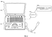
図2は、3D超音波データを収集するように構成された探触子132を有する3D機能小型化超音波システム130を表している。図示していないが探触子132は、図1の探触子106に関連して上で検討したような2Dアレイ状のトランスジューサ素子104、並びにtx SAP124及びrx SAP126を有している。オペレータからコマンドを受け取るためにユーザインタフェース134(一体型ディスプレイ136を含むこともあり得る)が設けられている。本明細書で使用する場合に「小型化」とは、超音波システム130がハンドヘルド型または携行式のデバイスであるか、あるいはスタッフの手中、ポケット、書類カバンサイズのケース、あるいはリュックサックで持ち運べるように構成されていることを意味している。例えば超音波システム130は、例えば深さが概ね2.5インチ、幅が概ね14インチ、高さが概ね12インチの寸法を有する典型的なラップトップコンピュータのサイズを有する携行式デバイスとすることがある。超音波システム130は重さが約10ポンドであり、したがってオペレータにより容易に運搬可能とすることがある。さらに一体型ディスプレイ136(例えば、内部ディスプレイ)が設けられ、これが医用画像を表示するように構成されている。
FIG. 2 represents a 3D functional
超音波データは、有線式またはワイヤレス式のネットワーク140(または、例えばシリアルケーブルやパラレルケーブルあるいはUSBポートを介した直接接続)によって外部デバイス138に送られることがある。幾つかの実施形態では、外部デバイス138はディスプレイを有するコンピュータまたはワークステーションとすることがある。別法として外部デバイス138は、携行式超音波システム130からの画像データの受け取り並びに一体型ディスプレイ136を超える分解能を有することがある画像の表示またはプリントアウトが可能な単独の外部ディスプレイまたはプリンタとすることがある。
The ultrasound data may be sent to the
別の例では、超音波システム130は3D機能ポケットサイズ超音波システムとすることがある。一例として、ポケットサイズ超音波システムは幅が概ね2インチ、長さが概ね4インチ及び深さが概ね0.5インチであり、かつ重さは3オンス未満とすることがある。ポケットサイズ超音波システムは、ディスプレイ、ユーザインタフェース(例えば、キーボード)及び探触子に接続するための入力/出力(I/O)ポート(これらはすべて図示せず)を含むことがある。寸法、重量及び電力消費が異なる小型化超音波システムと接続した様々な実施形態を実現し得ることに留意すべきである。
In another example, the
図3は、2Dアレイに配列させた多数のトランスジューサ素子104からなる図1の探触子106などの超音波探触子の面を横断するように延びたアパーチャ170を表している。アパーチャ170はこの実施形態では三角形状に表した複数の受信サブアパーチャ172に分割される。この例では、176個の異なる受信サブアパーチャ172が存在している。受信サブアパーチャ172の各々は15個のトランスジューサ素子104(図1)を備える。受信サブアパーチャ172の各々は、rx SAP126などのrx SAPを介してビーム形成器110のうちの1つのチャンネルに接続されている。超音波の受信中に、トランスジューサ素子104から受け取った信号はrx SAP26内部にある独立の遅延(または、移相器)を通過させると共に、対応するシステムチャンネルに接続された単一の出力になるように互いに加え合わせられる。
FIG. 3 shows an
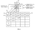
図4は、送信サブアパーチャ180と、2Dアレイの形とした送信サブアパーチャ組成の一部分202と、を表している。この一部分202は、非重複の矩形サブアレイの形に組み上げた複数の送信サブアパーチャ180を表している。各送信サブアパーチャ180は上で検討したようなトランスジューサ素子104をその各々が15個有する8つの三角形状の受信サブアパーチャ172を備える。したがって送信サブアパーチャ180は、全体で120個のトランスジューサ素子104を、水平(方位方向)軸181に沿って10個の隣接トランスジューサ素子104が延びかつ垂直(縦方向)軸197に沿って12個の隣接トランスジューサ素子104が延びるように配列させて有している。別の構成の受信サブアパーチャ172を使用することもある。送信サブアパーチャ180では、部分202全体にわたって複数の送信サブアパーチャが反復されている。送信サブアパーチャの各々は、既定群のトランスジューサ素子104に接続されており、また部分202内の送信サブアパーチャの各々は異なる既定群のトランスジューサ素子104に接続されている。例えば送信サブアパーチャ180は、第1及び第2の素子群198及び200によって形成された120個のトランスジューサ素子104からなる固定群に接続されている。
FIG. 4 represents a transmit sub-aperture 180 and a
超音波パルスの送信中に、8つの受信サブアパーチャ182〜194に関連付けされた8つのチャンネルが送信サブアパーチャ180内のトランスジューサ素子104を駆動させる。以下で検討するが、トランスジューサ素子104の各々は8つのチャンネルのうちのいずれかに接続させることができるが、この受信サブアパーチャ182〜194の構成による限定を受けない。
During transmission of the ultrasonic pulse, the eight channels associated with the eight receive sub-apertures 182-194 drive the
一実施形態では、第1、第2、第3及び第4の受信サブアパーチャ182、184、186及び188など水平方向軸181に沿った4つの隣接する受信サブアパーチャ172から受け取った信号は4つのrx SAP(図示せず)を包含する第1の集積回路内で処理され、かつ第5の、第6、第7及び第8の受信サブアパーチャ190、192、194及び196は第1の集積回路と同一とし得る第2の集積回路(図示せず)内で処理される。第1〜第4の受信サブアパーチャ182〜188は第1の素子群198を形成しており、また第5〜第8の受信サブアパーチャ190〜196は第2の素子群200を形成している。第1及び第2の素子群198及び200はまた、部分202内部でそれぞれ素子群k1及びk1+1と呼ばれる。部分202内部の第2の送信サブアパーチャ204はそれぞれ素子群k1+2及びk1+3を有する第1及び第2の群206及び208を有する。
In one embodiment, the signals received from four adjacent receive
図5は、送信動作中にトランスジューサ素子104をシステムチャンネルに接続するための交点スイッチの利用を概念的に示したブロック概要図を表している。受信回路は省略されていることを理解すべきである。第1、第2、第3及び第4の交点スイッチ210、212、214及び216を図示しており、またこれら各々はその内部にトランスジューサ素子104とシステムチャンネルを相互接続するための複数のスイッチ(図示せず)を有する。第1〜第4の交点スイッチ210〜216の各々は、トランスジューサ素子104を相互接続する第1の側226とシステムチャンネルを相互接続する第2の側228を有するような構成としている。交点スイッチのすべてについて検討していないが、この説明は残りの交点スイッチにも適用されることに留意すべきである。第1の交点スイッチ210は第1の素子群198(素子群k1)に接続されており、第2の交点スイッチ212は第2の素子群200(素子群k1+1)に接続されている。交点スイッチの各々に8つのチャンネルが接続されており、これが図1のシステム送信器102及び受信器108のそれぞれに関する信号を伝達している。これらのチャンネルは、第1及び第2のチャンネル群218及び220が第1及び第2の交点スイッチ210及び212に接続されかつ第3及び第4のチャンネル群222及び224が第3及び第4の交点スイッチ214及び216に接続されるような4つのチャンネルからなる群として図示している。一例として、第1及び第2の交点スイッチ210及び212の組み合わせのことをtx SAP124と呼ぶことがあり、また第3及び第4の交点スイッチ214及び216の組み合わせのことをtx SAP124と呼ぶことがあり、tx SAP124の各々は、120個のトランスジューサ素子104を駆動するために8つのシステム送信チャンネルに接続されている。
FIG. 5 shows a block schematic diagram conceptually illustrating the use of an intersection switch to connect the
トランスジューサ素子104の各々は交点スイッチを用いて、対応するチャンネルのうちの1つ、幾つか、あるいは任意のチャンネルと接続させることがある。所与のトランスジューサ素子104及び所与の送信ベクトルについて、交点スイッチのうちの閉じられる可能性があるのは多くとも1つのスイッチだけである。この例では、第1の素子群198の内部に60個のトランスジューサ素子104が存在しており、第1及び第2のチャンネル群218及び220によって送信動作と受信動作の両方が可能な8つのチャンネルが提供されている。したがってトランスジューサ素子104の各々について(480個スイッチからなる総体について)交点スイッチ210の内部にトランスジューサ素子104の各々を第1及び第2のチャンネル群218及び220の内部のチャンネルの各々に接続させる能力を提供する最大で8個のスイッチを存在させることがある。所与の送信ベクトルについてその交点スイッチは、交点スイッチ内の480個のスイッチのうちのどれを閉じるかを選択するようにプログラムされている。この選択は、当該トランスジューサ素子104に関連付けされた遅延に基づくことがある(これについては、以下で検討することにする)。最大で60個のスイッチ(各トランスジューサ素子104ごとに1つ)が同時に閉じられることになる。
Each
別法として、有する内部スイッチの全体数をより少なくした交点スイッチを設けることがある。したがって、1つまたは複数のトランスジューサ素子104を1つまたは複数のチャンネルに取り付けることができる、ただしそのチャンネルの数は8個未満である。例えば、トランスジューサ素子104のそれぞれについて8つのスイッチではなく、2個または4個のチャンネルのそれぞれに対して接続させるように2個または4個のスイッチを利用可能とさせることがある。別の例では、トランスジューサ素子104のうちのある部分組に単一のスイッチを設け、送信に使用されているときに当該トランスジューサ素子104が常に同じチャンネルに接続されるようにすることがある。このケースでは、別のトランスジューサ素子104に複数のスイッチが設けられることがある。交点スイッチを「疎らにする(sparsing)」ことによってスイッチの数を減らすと、集積回路を作成するのに要するシリコン領域の量が低減される。
Alternatively, an intersection switch having a smaller total number of internal switches may be provided. Thus, one or
図6は送信構成の一例を表している。アパーチャ420は2Dアレイ状のトランスジューサ素子104を有するように図示している。この例では2Dアレイは、60×48個のトランスジューサ素子104を備える。2Dアレイは、第1、第2及び第3の送信サブアパーチャ422、424及び426などその各々が10×12個のトランスジューサ素子104からなる2Dアレイを有するような24個の送信サブアパーチャに分割されている。送信サブアパーチャのうちのすべてを参照番号によって特定しているわけではない。
FIG. 6 shows an example of a transmission configuration. The
送信サブアパーチャの各々の内部にあるトランスジューサ素子104はビームステアリング方向に基づいた送信構成を形成するようにシステムチャンネルと接続されている。このビームステアリング方向は1つまたは複数の焦点に基づくことがあり、この例ではその焦点は、探触子面に沿って下方向に真っ直ぐとなるか、探触子の視野域を基準として真っ直ぐとなっている。第2の送信サブアパーチャ424のトランスジューサ素子104についてより詳細に図示している。第2の送信サブアパーチャ424内部のトランスジューサ素子104からなる異なる組は8つのシステムチャンネル内部の異なるチャンネルにマッピングされている。例えばトランスジューサ素子104の第1組428、第2組430、第3組432、第4組434、第5組436、第6組438、第7組440及び第8組442は、第1、第2、第3、第4、第5、第6、第7及び第8のシステムチャンネル(図示せず)のそれぞれにマッピングさせることができる。
図7は、焦点を一方の側にステアリングするようにマッピングした送信構成を有するアパーチャ450を表している。ここでもアパーチャ450は24個の送信サブアパーチャに分離されると共に、送信サブアパーチャ452を示している。ビームステアリング方向は探触子106の視野域のある側に向いている。送信サブアパーチャ452のトランスジューサ素子104は、図示したような送信構成においてシステムチャンネル(図示せず)にマッピングされている。トランスジューサ素子104の第1組454、第2組456、第3組458、第4組460、第5組462、第6組464、第7組466及び第8組468は、第1、第2、第3、第4、第5、第6、第7及び第8のシステムチャンネルにマッピングさせることができる。
FIG. 7 illustrates an
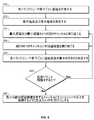
図8は、送信中におけるトランスジューサ素子104のチャンネルに対するマッピングを決定するための方法を表している。本方法は各送信サブアパーチャ180ごとに実行され、超音波ビームを動的に焦点合わせするように超音波の検査過程全体にわたって反復実行されることがある。270では、プロセッサ116(図1参照)が各トランスジューサ素子104ごとに遅延を計算する。この遅延は、周知の技法を用いて計算されることがあり、また焦点、局所的ステアリング角すなわち方向、及び/または探触子106のアパーチャ170(図3)内部の箇所に基づくなど、その送信サブアパーチャに特異的な方向(すなわち、ビームステアリング)セットアップ情報に基づくことがある。別法としてその遅延は、ビーム形成器110及び/またはサブアパーチャ制御器128によって計算されることがある。272では、プロセッサ116が遅延を比較して最大及び最小遅延を決定する。274では、プロセッサ116が2つの単独のチャンネルに対して最大遅延及び最小遅延を割り当て、また276では、プロセッサ116が残りのチャンネルに対して中間的遅延値を割り当てる。
FIG. 8 represents a method for determining the mapping of a
例えばプロセッサ116は、図5の第1の素子群198内部にあるトランスジューサ素子104のそれぞれごとに遅延を決定することがある。単に一例としてその最小遅延をゼロとすることがあり、また第1のチャンネル群218内部の第1のチャンネルに割り当てられることがある。最大遅延は500ナノ秒とすることがあり、また第2のチャンネル群220内部の第4のチャンネルに割り当てられることがある。中間的遅延値は最大及び最小遅延に基づいており、例えば均一量子化を用いて決定されることがある。次いでこの中間的遅延値が残りの6つのチャンネルに割り当てられる。任意のチャンネルに対して任意の遅延を割り当てることができ、また本明細書で検討した順序例示に限定するものでないことを理解すべきである。
For example, the
別の実施形態では、トランスジューサ素子104の対チャンネル割り当て、並びにチャンネル遅延分布(274及び276で決定)を最適化基準の最小化に従って設定することがある。この基準は、平均2乗遅延誤差の平均値とすることや、送信ビームプロフィールの最大サイドローブレベルの最小化とすることがある。
In another embodiment, the
278では、プロセッサ116がトランスジューサ素子104の各々の遅延を8つのチャンネルに割り当てた8つの遅延の各々と比較し、各トランスジューサ素子104ごとに遅延誤差の最小の大きさを決定する。280では、プロセッサ116がチャンネル間のバラツキを最小化するために負荷バランス調整を実施すべきか否かを決定する。第1及び第2のチャンネル群218及び220内部の8つのチャンネルのうちの幾つかには、別のチャンネルと比べてより多くのトランスジューサ素子104が割り当てられており、これにより所与の送信ベクトルに関して異なる送信チャンネルに対する電気的負荷が同じでなくなることがある。システム送信器102は有限の出力インピーダンスを有しており、また各チャンネルに対する負荷が異なると幾つかの追加的な振幅及び/または遅延バラツキを生じることがある。探触子ケーブル142の直列抵抗もまた、負荷バランス調整が実施されないと同様の誤差を生じさせることがある。したがって本方法は274及び/または276に戻り、1つまたは複数のチャンネルに対して割り当てた遅延値を修正すると共に、調整済み遅延値に基づいて各トランスジューサ素子104ごとに遅延誤差の最小の大きさを決定することがある。
At 278,
282では、サブアパーチャ制御器128が、プロセッサ116からの情報に基づいた最小の絶対遅延誤差を与えるような対応するチャンネルにトランスジューサ素子104を接続またはマッピングするように交点スイッチ210をプログラムまたは制御する。これによって送信サブアパーチャの送信構成が形成される。各送信サブアパーチャが異なる送信構成を有することがあり、またその送信構成はビームごとに変更されることや、送信サブアパーチャに関して異なる焦点などのオペレータ入力に基づいて時間の経過と共に変更されることがある。上の例について続けると、交点スイッチ210は、送信動作中に第1の素子群198内のトランスジューサ素子104の各々を第1及び第2のチャンネル群218及び220内部のチャンネルのうちの1つに接続するようにプログラムされている。任意選択では各送信動作中に交点スイッチ210がそのトランスジューサ素子104のすべてを接続しないことがある。システムチャンネルの各々に割り当てた遅延を送信器102に連絡するなど、ビーム形成器110及び/または送信器102に対して送信構成情報が伝達される。
At 282, the
典型的には、有するステアリング角が小さい送信ベクトルでは遅延誤差が小さいことになる。遅延誤差の大きさはステアリングの量が大きくなるに連れて増大することがある。より大きなステアリング角を有する送信ビームに関するビームプロフィールを改善するには、最大遅延値を例えば送信している中心周波数の2周期に抑制することがある。より大きな遅延を有するトランスジューサ素子104は、波形に関する所望の位相調整関係を保存するように中心周波数の1周期に対応する時間を加算または減算することによってこの領域内に「ラッピング(wrapped)」させることがある。別法として、トランスジューサ素子104を任意のチャンネルに割り当てることによって送信中に相対的に非常に大きい遅延を有するトランスジューサ素子104をオフにすることがある。しかしこれによって、送信時にある程度の歯抜け(Sparse)を生じることになる。この歯抜けは最小とすることはできるが、送信サブアパーチャ180のうちの幾つかについてある空間方向に関してアレイ表面または探触子106のアパーチャ170全体にわたって生じることがある。
Typically, a transmission vector having a small steering angle has a small delay error. The magnitude of the delay error may increase as the amount of steering increases. To improve the beam profile for a transmit beam with a larger steering angle, the maximum delay value may be constrained to, for example, two periods of the transmitting center frequency. A
さらに、交点スイッチ210内の各スイッチ素子は有限のオン抵抗を有することがある。この抵抗は、予測される電気的負荷(トランスジューサ素子の電気的インピーダンスと相互接続キャパシタンスの和)を大きく下回るように選択されることがある。これによって熱発生を最小化すると共に、製造の一貫性を向上させることができる。さらにその送信信号が2*f0、3*f0、4*f0、等々の高調波を比較的少ない量だけ含んだ中心周波数f0におけるサイン(sine)ラインバーストよりなる場合に、探触子内のパワー損失を低減することができる。
Further, each switch element in the
遅延誤差は、1つの送信ベクトル内の異なる送信チャンネルと異なる送信ベクトル間の両者に関して問題となる。例えば送信ベクトルが焦点を無限大の距離とした探触子106の面と直角となっていれば、トランスジューサ素子104のすべてはゼロ遅延など同じ遅延を有することになる。このケースでは、第1及び第2のチャンネル群218及び220内部の8つすべての送信チャンネルに対して実質的に同一の信号を割り当て、120個のトランスジューサ素子104を1つのチャンネルに接続して残りの7個のチャンネルを未使用のままとするのではなく15個のトランスジューサ素子を8つのチャンネルの各々に接続することが望ましい。この例では、負荷バランス調整(図8の280)は、チャンネル間でのトランスジューサ素子104の再配分によって実施されることがある。別の実施形態では、異なる中間的遅延を選択して再配分を実施することがある。
Delay error is a problem both for different transmission channels within one transmission vector and between different transmission vectors. For example, if the transmit vector is perpendicular to the surface of the
図4の第1〜第8の受信サブアパーチャ182〜196など受信サブアパーチャと比較して送信サブアパーチャ180のサイズが大きいことが、送信中にトランスジューサ素子104に関連付けされる遅延誤差の低減に役立つことがある。典型的な受信サブアパーチャの大きさはトランスジューサ素子104の15〜25個の範囲にある一方、一実施形態における送信サブアパーチャ180は120個トランスジューサ素子104を有する。一実施形態では、1つの交点スイッチがトランスジューサ素子104のすべてをチャンネルのすべてに接続するようにアレイの全体に及ぶことがある。
The large size of the
幾つかの実施形態では、送信用電子回路を受信器電子回路と同じ方法で区分することが望ましい。このことは1つの送信サブアパーチャが2つの受信ASICにわたる場合であっても可能である。例えば図4に戻ると上で検討したように、第1〜第4の受信サブアパーチャ182〜188は第1の受信ASICによって処理され、かつ第5〜第8の受信サブアパーチャ190〜196は第2の受信ASICによって処理される。図5は、図4のトポロジーを得るためにはその各々がサイズ8×15の交点スイッチ1つを包含する送信ASICの対をどのようにして相互接続させるかを表している。 In some embodiments, it may be desirable to partition the transmitting electronics in the same way as the receiver electronics. This is possible even if one transmit sub-aperture spans two receive ASICs. For example, returning to FIG. 4, as discussed above, the first through fourth receive sub-apertures 182-188 are processed by the first receive ASIC, and the fifth through eighth receive sub-apertures 190-196 are the first ones. Processed by two receiving ASICs. FIG. 5 shows how the pairs of transmit ASICs, each containing one 8 × 15 intersection switch, can be interconnected to obtain the topology of FIG.
図9は、第1、第2、第3及び第4の交点スイッチ360、362、364及び366を備えた交点スイッチマトリックス310を用いたtx SAPに関する送信/受信アーキテクチャ300を表している。第1、第2、第3及び第4のrx SAP302、304、306及び308を図示している。アーキテクチャ300は送信SAPのうちの半分のみを含む。第1、第2、第3及び第4の入力送受信切替(t/r)スイッチ312、314、316及び318は受信入力ライン328、330、332及び334によって第1〜第4のrx SAP302〜308の入力のそれぞれに接続されている。第1、第2、第3及び第4の出力t/rスイッチ320、322、324及び326は受信出力ライン336、338、340及び342によって第1〜第4のrx SAP302〜308の出力のそれぞれに接続されている。送信中において第1、第2、第3及び第4の入力t/rスイッチ312〜318並びに第1〜第4の出力t/rスイッチ320〜326は、第1〜第4のrx SAP302〜308の入力と出力のそれぞれを切断し、第1〜第4のrx SAP302〜308を高電圧送信パルスから保護している。受信周期中は入力及び出力t/rスイッチ312〜326は閉じられる。受信中では、rx SAP出力が短絡しないように、交点スイッチマトリックス310内部のすべてのスイッチが開放される。
FIG. 9 depicts a transmit / receive
rx SAP302、304、306及び308のそれぞれに対するcfg0、cfg1、cfg2及びcfg3入力が例えばシフトレジスタ・チェーン(別のシステムアーキテクチャを用いることもある)を用いて制御される場合について、交点スイッチ360〜366並びに内部ビーム形成器の設定を図9に表している。1つのASICの交点スイッチ360〜366内部にあるスイッチの各々がシフトレジスタの1ビットに割り当てられると共に、当該ビットの値によってスイッチの開放または閉鎖が判定される。
Intersection switches 360-366 for the case where the cfg0, cfg1, cfg2, and cfg3 inputs for each of the
図10は、図9のアーキテクチャ300の機能が、例えばtx SAP350とrx SAP352などどのようにして2つの部分に分割されるのかを表している。一実施形態では、tx及びrx SAP350及び352が2つの単独のシリコンダイ上に形成されている。tx SAP350は典型的には、高電圧能力を有するシリコン処理(典型的な送信パルスは+/−50〜100ボルト)を用いて形成されており、一方rx SAP352は標準の低電圧シリコン処理で形成されることがある。次いでこの2つのダイを互いに重ね合わせることがある。別法として、高電圧で低ノイズのアナログ設計並びにディジタル制御の扱いが可能なシリコン処理に基づいた単一ダイ構成も可能となり得る。任意選択では、スタック内にディジタル制御用電子回路が第3のダイとして付加されることがある。
FIG. 10 illustrates how the functionality of the
図11は、tx及びrx SAPダイ354及び356の重ね合わせを表している。この重ね合わせ構成はコンパクトであり、また必要とするオフチップ接続の数が減少する。例えばtxとrx SAPダイ354及び356の間だけに15個の受信入力ライン328〜334(図9参照)と受信出力ライン336〜342が接続されており、これによって別の集積回路(IC)への1つまたは複数の外側接続を回避することが可能である。 FIG. 11 represents the superposition of the tx and rx SAP dies 354 and 356. This superposition configuration is compact and reduces the number of off-chip connections required. For example, 15 receive input lines 328-334 (see FIG. 9) and receive output lines 336-342 are connected only between tx and rx SAP dies 354 and 356, thereby leading to another integrated circuit (IC). It is possible to avoid one or more outer connections.
図9に戻り一実施形態では、第1〜第4の入力t/rスイッチ312〜318、第1〜第4のrx SAP302〜308並びに第1〜第4の出力t/rスイッチ320〜326が除去されることがある。この例では第1〜第4の交点スイッチ360〜366が、送信動作と受信動作の両方の期間において選択群のトランスジューサ素子104をシステム送信器102及び受信器108に接続している双方向スイッチとして使用されることになる。したがってこの実施形態では必要となる電子回路がより少ない。
Returning to FIG. 9, in one embodiment, the first to fourth input t / r switches 312 to 318, the first to
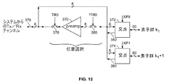
図12は、送信動作と受信動作のそれぞれに関して交点スイッチを用いてシステムチャンネルを送信及び受信サブアパーチャに接続する一例を表している。任意選択では、交点スイッチ372及び374とチャンネル群376の間に前置増幅器370を配置させることがある。送信/受信スイッチ378及び380は、この任意選択の前置増幅器370の両側に配置させることがあり、また送信動作中は開放させかつ受信動作中は閉じさせることがある。信号を受け取る際に交点スイッチ372は、素子群k1を備える受信サブアパーチャ内部のトランスジューサ素子104を第1〜第4のチャンネルのうちの1つ(例えば、第1のチャンネル382)に接続するようにプログラムされることがあり、また交点スイッチ374は、素子群k1+1を備える受信サブアパーチャ内部のトランスジューサ素子104を、例えば第2のチャンネル384に接続するようにプログラムされることがある。交点スイッチ372及び374は、受信動作中はトランスジューサ素子104を指定のチャンネルに割り当てるために送信構成と異なる設定受信構成を用いることがある。
FIG. 12 shows an example of connecting the system channel to the transmission and reception sub-apertures using an intersection switch for each of the transmission operation and the reception operation. Optionally, a
図13は、送信中の超音波ビームのステアリングに使用できる4種類の送信サブアパーチャ構成の実施形態を表している。第1、第2、第3及び第4の送信構成230、232、234及び236を表している。送信構成は、少なくとも各送信サブアパーチャがビームを所望の方向にステアリングする局所的ステアリング方向に基づいて選択されることがある。一実施形態では、4つの三角形受信サブアパーチャの各群を4つのシステムチャンネルに接続させることがある。
FIG. 13 illustrates an embodiment of four transmit sub-aperture configurations that can be used for steering an ultrasonic beam during transmission. The first, second, third and
再度図4に戻ると、送信サブアパーチャ180は互いに水平の重ね合わせ構成で配列させた第1及び第2の素子群198及び200に分割されている。図4の構成は、第1の素子群238及び第2の素子群240が互いに対して水平で重ね合わせられている第1の送信構成230として図示している。第2の送信構成232は送信サブアパーチャを、互いに横に並べた第1及び第2の素子群242及び244に分割している。第3の送信構成234は送信サブアパーチャを、斜めに第1及び第2の素子群246及び248に分割しており、また第4の送信構成236は送信サブアパーチャを、斜めに第1及び第2の素子群250及び252に分割している。単に一例として第1の送信構成230は、図の表面を基準として上下方向にビームをステアリングすることがあり、第2の送信構成232は左右方向にビームをステアリングすることがあり、第3の送信構成234は左上隅/右下隅の方向にビームをステアリングすることがあり、また第4の送信構成236は右上隅/左下隅の方向にビームをステアリングすることがある。
Returning again to FIG. 4, the
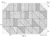
図14は、焦点256が図示した送信アパーチャ254の面から外方に向かいかつ送信アパーチャ254の右上隅に向かうような位置にして送信アパーチャ254を表している。換言すると図示した焦点256は実際の焦点箇所の投影となっている。送信アパーチャ254は、その各々が第1及び第2のトランスジューサ素子群を有するような複数の送信サブアパーチャに分割されている。複数の遅延線258によって同じ遅延を有する送信アパーチャ254を通過する領域を示しており、遅延線の方向はその送信ビームに関する選択したステアリング方向及び焦点に依存する。この例では、送信サブアパーチャの各々は、焦点256に対する所望のステアリングを実現するように個別に構成されている。例えば第1のサブアパーチャ260は第4の送信構成236で構成されており、また第2のサブアパーチャ262は第2の送信構成232で構成されている。
FIG. 14 illustrates the
図15は、図13及び14の実施形態に関するハードウェア実現形態を表している。より小さい交点スイッチマトリックス390を使用することがあり、また所望の群構成(第1の送信構成230、第2の送信構成232、その他)に従ってプログラムされたマルチプレクサマトリックス392を先行させることがある。マルチプレクサマトリックス392を通って流れる送信電流は、交点スイッチマトリックス390を通って流れる電流よりかなり大きい。したがってマルチプレクサマトリックス392のオン抵抗は、交点スイッチマトリックス390内部の交点スイッチのオン抵抗と比べてより小さいこと(例えば、少なくとも4分の1のこと)がある。トランスジューサ素子104の対チャンネル遅延割り当て及びスイッチプログラミングは、図8の接続において上で記載のようにして決定することができる。
FIG. 15 represents a hardware implementation for the embodiment of FIGS. A smaller
図16は、送信サブアパーチャ400が複数の正方形受信サブアパーチャ402を備えるような実施形態を表している。この例では、各送信サブアパーチャ400が4つの受信サブアパーチャ402を有している。送信サブアパーチャ400は図4において上で検討したような第1及び第2の素子群404及び406に分割されることがある。第1及び第2の素子群404及び406は第1の送信構成230(図13参照)で図示しており、また第2の送信構成232で構成されることもある。
FIG. 16 represents an embodiment where the transmit sub-aperture 400 comprises a plurality of square receive
少なくとも1つの実施形態の技術的効果は、送信動作中に探触子のトランスジューサ素子を非重複の矩形送信サブアパーチャに分割し送信ビームを所望の方向にステアリングすることである。送信サブアパーチャの各々は複数の受信サブアパーチャを含むことがある。送信サブアパーチャは異なる送信構成で個別に構成することができる。遅延誤差を減少させるために、各送信サブアパーチャ内のトランスジューサ素子は当該トランスジューサ素子の遅延に基づいてシステムチャンネルにマッピングさせている。 The technical effect of at least one embodiment is to divide the transducer element of the probe into non-overlapping rectangular transmit sub-apertures and steer the transmit beam in the desired direction during transmit operations. Each transmit sub-aperture may include a plurality of receive sub-apertures. The transmission sub-apertures can be individually configured with different transmission configurations. In order to reduce the delay error, the transducer elements in each transmission sub-aperture are mapped to system channels based on the delay of the transducer elements.
上の記述は例示であって限定でないことを理解されたい。例えば上述の実施形態(及び/または、その態様)は、互いに組み合わせて使用されることがある。さらに、具体的な状況や材料を本発明の教示に適応させるように本趣旨を逸脱することなく多くの修正を実施することができる。本明細書に記載した材料の寸法及びタイプは本発明のパラメータを規定することを意図しており、これらは決して限定ではなく実施形態の例示である。上の記述を検討することにより当業者には別の多くの実施形態が明らかとなろう。本発明の範囲はしたがって、添付の特許請求の範囲、並びに本請求範囲が規定する等価物の全範囲を参照しながら決定されるべきである。添付の特許請求の範囲では、「を含む(including)」や「ようになった(in which)」という表現を「を備える(comprising)」や「であるところの(wherein)」という対応する表現に対する平易な英語表現として使用している。さらに添付の特許請求の範囲では、「第1の」、「第2の」及び「第3の」その他の表現を単にラベル付けのために使用しており、その対象に対して数値的な要件を課すことを意図したものではない。さらに、添付の特許請求の範囲の限定は手段プラス機能形式で記載しておらず、また35 U.S.C.§112、第6パラグラフに基づいて解釈されるように意図したものでもない(ただし、本特許請求の範囲の限定によって「のための手段(means for)」の表現に続いて追加的な構造に関する機能排除の記述を明示的に用いる場合を除く)。また、図面の符号に対応する特許請求の範囲中の符号は、単に本願発明の理解をより容易にするために用いられているものであり、本願発明の範囲を狭める意図で用いられたものではない。そして、本願の特許請求の範囲に記載した事項は、明細書に組み込まれ、明細書の記載事項の一部となる。
It should be understood that the above description is illustrative and not restrictive. For example, the above-described embodiments (and / or aspects thereof) may be used in combination with each other. In addition, many modifications may be made without departing from the spirit of the invention to adapt specific situations and materials to the teachings of the invention. The material dimensions and types described herein are intended to define the parameters of the present invention, which are by no means limiting and are exemplary of embodiments. Many other embodiments will be apparent to those of skill in the art upon reviewing the above description. The scope of the invention should, therefore, be determined with reference to the appended claims, along with the full scope of equivalents to which such claims define. In the appended claims, the expressions “including” and “in what” are used in conjunction with the corresponding expressions “comprising” and “where”. Is used as a plain English expression for. Further, in the appended claims, the “first”, “second” and “third” other expressions are merely used for labeling and numerical requirements for the subject matter. It is not intended to impose. Further, the limitations of the appended claims are not described in means-plus-functional form, and 35 U.S. Pat. S. C. 112, nor is it intended to be construed under the sixth paragraph (however, with respect to additional structure following the expression “means for” by limitation of the scope of the claims) Except when explicitly using the description of function exclusion). Further, the reference numerals in the claims corresponding to the reference numerals in the drawings are merely used for easier understanding of the present invention, and are not intended to narrow the scope of the present invention. Absent. The matters described in the claims of the present application are incorporated into the specification and become a part of the description items of the specification.
100 超音波システム
102 送信器
104 トランスジューサ素子
106 探触子
108 受信器
110 ビーム形成器
112 RFプロセッサ
114 RF/IQバッファ
116 プロセッサ
118 ディスプレイ
120 ユーザ入力
124 送信サブアパーチャプロセッサ(tx SAP)
126 受信サブアパーチャプロセッサ(rx SAP)
128 SAP制御器
130 小型化超音波システム
132 探触子
134 ユーザインタフェース
136 一体型ディスプレイ
138 外部デバイス
140 ネットワーク
142 ケーブル
144 マイクロフォン
170 アパーチャ
172 受信サブアパーチャ
180 送信サブアパーチャ
181 水平軸
182 受信サブアパーチャ
184 受信サブアパーチャ
186 受信サブアパーチャ
188 受信サブアパーチャ
190 受信サブアパーチャ
192 受信サブアパーチャ
194 受信サブアパーチャ
196 受信サブアパーチャ
197 垂直(縦方向)軸
198 第1の素子群
200 第2の素子群
202 送信サブアパーチャ組成の一部分
204 送信サブアパーチャ
206 第2の素子群
208 第1の素子群
210 交点スイッチ
212 交点スイッチ
214 交点スイッチ
216 交点スイッチ
218 第1のチャンネル群
220 第2のチャンネル群
222 第3のチャンネル群
224 第4のチャンネル群
226 第1の側
228 第2の側
230 第1の送信構成
232 第2の送信構成
234 第3の送信構成
236 第4の送信構成
238 第1の素子群
240 第2の素子群
242 第1の素子群
244 第2の素子群
246 第1の素子群
248 第2の素子群
250 第1の素子群
252 第2の素子群
254 送信アパーチャ
256 焦点
258 遅延線
260 第1のサブアパーチャ
262 第2のサブアパーチャ
300 送信/受信アーキテクチャ
302 rx SAP
304 rx SAP
306 rx SAP
308 rx SAP
310 交点スイッチマトリックス
312 入力t/rスイッチ
314 入力t/rスイッチ
316 入力t/rスイッチ
318 入力t/rスイッチ
320 出力t/rスイッチ
322 出力t/rスイッチ
324 出力t/rスイッチ
326 出力t/rスイッチ
328 受信入力ライン
330 受信入力ライン
332 受信入力ライン
334 受信入力ライン
336 受信出力ライン
338 受信出力ライン
340 受信出力ライン
342 受信出力ライン
350 tx SAP
352 rx SAP
354 tx SAPダイ
356 rx SAPダイ
360 交点スイッチ
362 交点スイッチ
364 交点スイッチ
366 交点スイッチ
370 前置増幅器
372 交点スイッチ
374 交点スイッチ
376 チャンネル群
378 送信/受信スイッチ
380 送信/受信スイッチ
382 第1のチャンネル
384 第2のチャンネル
390 交点スイッチマトリックス
392 マルチプレクサマトリックス
400 送信サブアパーチャ
402 正方形受信サブアパーチャ
404 第1の素子群
406 第2の素子群
420 アパーチャ
422 送信サブアパーチャ
424 送信サブアパーチャ
426 送信サブアパーチャ
428 第1組のトランスジューサ素子
430 第2組のトランスジューサ素子
432 第3組のトランスジューサ素子
434 第4組のトランスジューサ素子
436 第5組のトランスジューサ素子
438 第6組のトランスジューサ素子
440 第7組のトランスジューサ素子
442 第8組のトランスジューサ素子
450 アパーチャ
452 送信サブアパーチャ
454 第1組のトランスジューサ素子
456 第2組のトランスジューサ素子
458 第3組のトランスジューサ素子
460 第4組のトランスジューサ素子
462 第5組のトランスジューサ素子
464 第6組のトランスジューサ素子
466 第7組のトランスジューサ素子
468 第8組のトランスジューサ素子
100
126 Receive Sub-Aperture Processor (rx SAP)
128
304 rx SAP
306 rx SAP
308 rx SAP
310
352 rx SAP
354 tx SAP die 356 rx SAP die 360
Claims (10)
送信電気信号を発生させるための送信器(102)と、
交点スイッチを備え、前記既定群のトランスジューサ素子(104)内部にあるトランスジューサ素子(104)をビームステアリング方向に基づいた送信構成で送信器(102)とマッピングさせるための少なくとも1つの送信サブアパーチャプロセッサ(tx SAP)(124)と、
その間で送信信号を伝達するために送信器(102)及び交点スイッチと相互接続させた複数のシステムチャンネルと、
前記既定群のトランスジューサ素子(104)内部で送信構成に基づいて前記複数のシステムチャンネルのうちの1つにより駆動させるトランスジューサ素子(104)を選択するために交点スイッチを制御するように構成されたSAP制御器(128)と、
を備え、
前記複数の受信素子は受信サブアパーチャを形成するように構成されており、前記少なくとも1つの送信サブアパーチャは少なくとも2つの隣接する受信サブアパーチャを備え、
前記既定群のトランスジューサ素子(104)内の個々のトランスジューサ素子(104)が前記交点スイッチを使用して前記複数のシステムチャンネルのいずれとも接続されることができる、超音波システム(100)。 A probe (106) including a two-dimensional (2D) transducer element array (104) forming an aperture (170) having a plurality of receiving elements configured to receive an ultrasound signal, the transducer (106) A probe (106) forming at least one transmit sub-aperture within the aperture (170) configured to be interconnected with a predetermined group of transducer elements (104); ,
A transmitter (102) for generating a transmitted electrical signal;
At least one transmit sub-aperture processor comprising an intersection switch for mapping the transducer elements (104) within the predetermined set of transducer elements (104) with a transmitter (102) in a transmit configuration based on beam steering direction ( tx SAP) (124),
A plurality of system channels interconnected with a transmitter (102) and a cross point switch to transmit transmission signals therebetween;
An SAP configured to control an intersection switch to select a transducer element (104) to be driven by one of the plurality of system channels based on a transmission configuration within the predetermined group of transducer elements (104). A controller (128);
With
The plurality of receiving elements are configured to form a receiving sub-aperture, wherein the at least one transmitting sub-aperture comprises at least two adjacent receiving sub-apertures;
An ultrasound system (100), wherein individual transducer elements (104) within the predefined group of transducer elements (104) can be connected to any of the plurality of system channels using the intersection switch.
前記既定群のトランスジューサ素子(104)内のトランスジューサ素子(104)の各々に関連付けした遅延を決定するように構成されたプロセッサ(116)であって、該遅延は少なくともビームステアリング方向に基づいており、前記少なくとも1つの送信サブアパーチャプロセッサ(tx SAP)(124)は、既定群のトランスジューサ素子(104)内部のトランスジューサ素子(104)のうちの少なくとも1つを該遅延に基づいて前記システムチャンネルのうちの1つのチャンネルに割り当てるように構成されているプロセッサ(116)と、
をさらに備える請求項1に記載の超音波システム(100)。 A system channel interconnected with the transmitter (102) for transmitting transmission signals;
A processor (116) configured to determine a delay associated with each of the transducer elements (104) within the predetermined group of transducer elements (104), the delay being based at least on a beam steering direction; The at least one transmit sub-aperture processor (tx SAP) (124) determines at least one of the transducer elements (104) within a predetermined group of transducer elements (104) of the system channels based on the delay. A processor (116) configured to allocate to one channel;
The ultrasound system (100) of claim 1, further comprising:
前記受信サブアパーチャの各々は、前記ビーム形成器(110)の1つのチャンネルに接続されている、請求項1または2に記載の超音波システム(100)。The ultrasound system (100) of claim 1 or 2, wherein each of the receive sub-apertures is connected to one channel of the beamformer (110).
第1及び第2の側を有し、超音波信号を送信するように構成された送信サブアパーチャを形成する既定群のトランスジューサ素子と前記第1の側において相互接続されている少なくとも1つの構成可能交点スイッチと、
少なくとも送信信号を伝達するように構成されると共に、前記少なくとも1つの構成可能交点スイッチと前記第2の側で相互接続しているシステムチャンネルと、
既定群のトランスジューサ素子内部のトランスジューサ素子の各々をシステムチャンネルに対して送信信号に関連付けされた遅延に基づいた送信構成でマッピングするために少なくとも1つの構成可能交点スイッチを制御するように構成されているサブアパーチャプロセッサ(SAP)制御器と、
を備え、
前記送信サブアパーチャは少なくとも2つの隣接する受信サブアパーチャを備え、
前記少なくとも1つの構成可能交点スイッチは複数のスイッチを有し、前記複数のスイッチの各々は既定群のトランスジューサ素子内の対応したトランスジューサ素子の各々に関連付けされ、前記少なくとも1つの構成可能交点スイッチによってトランスジューサ素子のうちの少なくとも1つをシステムチャンネルの1つと接続させる、超音波システム(100)。 A probe (106) including a two-dimensional (2D) transducer element array (104) forming an aperture (170) having a plurality of receiving elements configured to receive an ultrasonic signal;
At least one configurable element having a first and second side and interconnected at said first side with a predetermined group of transducer elements forming a transmission sub-aperture configured to transmit an ultrasound signal An intersection switch,
A system channel configured to communicate at least a transmission signal and interconnected with the at least one configurable intersection switch on the second side;
Configured to control at least one configurable intersection switch to map each of the transducer elements within a predetermined group of transducer elements to a system channel in a transmission configuration based on a delay associated with a transmission signal. A sub-aperture processor (SAP) controller;
With
The transmit sub-aperture comprises at least two adjacent receive sub-apertures;
The at least one configurable intersection switch has a plurality of switches, each of the plurality of switches being associated with a respective corresponding transducer element in a predetermined group of transducer elements, the transducer being configured by the at least one configurable intersection switch. An ultrasound system (100) that connects at least one of the elements to one of the system channels.
送信電気信号を発生させるための送信器(102)と、
前記既定群のトランスジューサ素子と前記送信器(102)とを相互接続する少なくとも1つの構成可能交点スイッチと、
その間で送信信号を伝達するために送信器(102)及び交点スイッチと相互接続させた複数のシステムチャンネルと、
を備え、
前記送信サブアパーチャは少なくとも2つの隣接する受信サブアパーチャを備え、
前記既定群のトランスジューサ素子内の少なくとも1つのトランスジューサ素子は前記少なくとも1つの構成可能交点スイッチを使用して、前記既定群のトランスジューサ素子内の他の少なくとも1つのトランスジューサ素子とは異なるシステムチャンネルに接続される、超音波システム(100)。
A probe (106) including a two-dimensional (2D) transducer element array (104) forming an aperture (170) having a plurality of receiving elements configured to receive an ultrasound signal, the transducer (106) A probe (106) forming at least one transmit sub-aperture within the aperture (170) configured to be interconnected with a predetermined group of transducer elements (104); ,
A transmitter (102) for generating a transmitted electrical signal;
At least one configurable intersection switch interconnecting the predetermined group of transducer elements and the transmitter (102);
A plurality of system channels interconnected with a transmitter (102) and a cross point switch to transmit transmission signals therebetween;
With
The transmit sub-aperture comprises at least two adjacent receive sub-apertures;
At least one transducer element in the predefined group of transducer elements is connected to a different system channel than the at least one other transducer element in the predefined group of transducer elements using the at least one configurable intersection switch. An ultrasound system (100).
Applications Claiming Priority (2)
| Application Number | Priority Date | Filing Date | Title |
|---|---|---|---|
| US11/770,126 | 2007-06-28 | ||
| US11/770,126 US8096951B2 (en) | 2007-06-28 | 2007-06-28 | Transmit beamforming in 3-dimensional ultrasound |
Publications (3)
| Publication Number | Publication Date |
|---|---|
| JP2009006141A JP2009006141A (en) | 2009-01-15 |
| JP2009006141A5 JP2009006141A5 (en) | 2013-03-14 |
| JP5411458B2 true JP5411458B2 (en) | 2014-02-12 |
Family
ID=40076137
Family Applications (1)
| Application Number | Title | Priority Date | Filing Date |
|---|---|---|---|
| JP2008159813A Active JP5411458B2 (en) | 2007-06-28 | 2008-06-19 | 3D ultrasonic transmission beam forming |
Country Status (3)
| Country | Link |
|---|---|
| US (2) | US8096951B2 (en) |
| JP (1) | JP5411458B2 (en) |
| DE (1) | DE102008002914A1 (en) |
Families Citing this family (60)
| Publication number | Priority date | Publication date | Assignee | Title |
|---|---|---|---|---|
| US7874991B2 (en) * | 2006-06-23 | 2011-01-25 | Teratech Corporation | Ultrasound 3D imaging system |
| US8096951B2 (en) * | 2007-06-28 | 2012-01-17 | General Electric Company | Transmit beamforming in 3-dimensional ultrasound |
| US10080544B2 (en) | 2008-09-15 | 2018-09-25 | Teratech Corporation | Ultrasound 3D imaging system |
| US20120179044A1 (en) | 2009-09-30 | 2012-07-12 | Alice Chiang | Ultrasound 3d imaging system |
| US20100113926A1 (en) * | 2008-10-31 | 2010-05-06 | General Electric Company | System and method for clutter filter processing for improved adaptive beamforming |
| WO2010055428A1 (en) * | 2008-11-11 | 2010-05-20 | Koninklijke Philips Electronics, N.V. | Configurable microbeamformer circuit for an ultrasonic diagnostic imaging system |
| EP2473112A4 (en) * | 2009-09-04 | 2014-03-26 | Univ Southern California | Fresnel-based beamforming for ultrasonic arrays |
| US20110060225A1 (en) * | 2009-09-09 | 2011-03-10 | General Electric Company | Ultrasound probe with integrated pulsers |
| JP5433429B2 (en) * | 2010-01-12 | 2014-03-05 | 株式会社東芝 | Ultrasonic probe |
| US9033888B2 (en) * | 2010-02-08 | 2015-05-19 | Dalhousie University | Ultrasound imaging system using beamforming techniques for phase coherence grating lobe suppression |
| US9575165B2 (en) * | 2010-05-25 | 2017-02-21 | General Electric Company | Ultrasound probe and ultrasound imaging system |
| US8430819B2 (en) * | 2010-05-28 | 2013-04-30 | General Electric Company | System and method for ultrasound imaging with a configurable receive aperture |
| JP5666873B2 (en) * | 2010-10-13 | 2015-02-12 | 富士フイルム株式会社 | Ultrasonic diagnostic equipment |
| KR101792590B1 (en) | 2011-04-26 | 2017-11-01 | 삼성전자주식회사 | Beamforming method, apparatus for performing the same, and medical imaging system |
| BR112014027597A2 (en) | 2012-05-09 | 2017-06-27 | Koninklijke Philips Nv | method of controlling an aperture of a transducer in conjunction with an ultrasound probe |
| US9239375B2 (en) | 2013-05-08 | 2016-01-19 | General Electric Company | Ultrasound probe with dynamic focus and associated systems and methods |
| WO2014185560A1 (en) * | 2013-05-13 | 2014-11-20 | 알피니언메디칼시스템 주식회사 | Transducer having front-end processor, image diagnosis device and method for processing signal thereof |
| US10584220B2 (en) * | 2016-02-26 | 2020-03-10 | Fina Technology, Inc. | Modified polymers and stable emulsions comprising the same |
| US10687787B2 (en) | 2016-03-04 | 2020-06-23 | Igor Yukov | Yukov tissue characterization method and apparatus |
| US10670716B2 (en) | 2016-05-04 | 2020-06-02 | Invensense, Inc. | Operating a two-dimensional array of ultrasonic transducers |
| US10656255B2 (en) | 2016-05-04 | 2020-05-19 | Invensense, Inc. | Piezoelectric micromachined ultrasonic transducer (PMUT) |
| US10315222B2 (en) | 2016-05-04 | 2019-06-11 | Invensense, Inc. | Two-dimensional array of CMOS control elements |
| US10445547B2 (en) | 2016-05-04 | 2019-10-15 | Invensense, Inc. | Device mountable packaging of ultrasonic transducers |
| US10600403B2 (en) * | 2016-05-10 | 2020-03-24 | Invensense, Inc. | Transmit operation of an ultrasonic sensor |
| US10441975B2 (en) | 2016-05-10 | 2019-10-15 | Invensense, Inc. | Supplemental sensor modes and systems for ultrasonic transducers |
| US10706835B2 (en) | 2016-05-10 | 2020-07-07 | Invensense, Inc. | Transmit beamforming of a two-dimensional array of ultrasonic transducers |
| US10539539B2 (en) | 2016-05-10 | 2020-01-21 | Invensense, Inc. | Operation of an ultrasonic sensor |
| US10408797B2 (en) | 2016-05-10 | 2019-09-10 | Invensense, Inc. | Sensing device with a temperature sensor |
| US10632500B2 (en) | 2016-05-10 | 2020-04-28 | Invensense, Inc. | Ultrasonic transducer with a non-uniform membrane |
| US11673165B2 (en) | 2016-05-10 | 2023-06-13 | Invensense, Inc. | Ultrasonic transducer operable in a surface acoustic wave (SAW) mode |
| US10562070B2 (en) | 2016-05-10 | 2020-02-18 | Invensense, Inc. | Receive operation of an ultrasonic sensor |
| US10452887B2 (en) | 2016-05-10 | 2019-10-22 | Invensense, Inc. | Operating a fingerprint sensor comprised of ultrasonic transducers |
| CA3030011A1 (en) | 2016-07-19 | 2018-01-25 | Shifamed Holdings, Llc | Medical devices and methods of use |
| US11090030B2 (en) * | 2016-11-10 | 2021-08-17 | Leltek Inc. | Ultrasound apparatus and ultrasound emission method |
| WO2018182836A1 (en) | 2017-03-30 | 2018-10-04 | Shifamed Holdings, Llc | Medical tool positioning devices, systems, and methods of use and manufacture |
| US10891461B2 (en) | 2017-05-22 | 2021-01-12 | Invensense, Inc. | Live fingerprint detection utilizing an integrated ultrasound and infrared sensor |
| US10474862B2 (en) | 2017-06-01 | 2019-11-12 | Invensense, Inc. | Image generation in an electronic device using ultrasonic transducers |
| US10643052B2 (en) | 2017-06-28 | 2020-05-05 | Invensense, Inc. | Image generation in an electronic device using ultrasonic transducers |
| WO2019109010A1 (en) | 2017-12-01 | 2019-06-06 | Invensense, Inc. | Darkfield tracking |
| US10997388B2 (en) | 2017-12-01 | 2021-05-04 | Invensense, Inc. | Darkfield contamination detection |
| US10984209B2 (en) | 2017-12-01 | 2021-04-20 | Invensense, Inc. | Darkfield modeling |
| US11151355B2 (en) | 2018-01-24 | 2021-10-19 | Invensense, Inc. | Generation of an estimated fingerprint |
| US10755067B2 (en) | 2018-03-22 | 2020-08-25 | Invensense, Inc. | Operating a fingerprint sensor comprised of ultrasonic transducers |
| JP7404369B2 (en) | 2018-08-23 | 2023-12-25 | ヌベラ・メディカル・インコーポレイテッド | Medical device positioning devices, systems, and methods of use and manufacture |
| FR3086063B1 (en) * | 2018-09-13 | 2022-11-11 | Moduleus | ULTRASOUND IMAGING DEVICE |
| WO2020102389A1 (en) | 2018-11-13 | 2020-05-22 | Shifamed Holdings, Llc | Medical tool positioning devices, systems, and methods of use and manufacture |
| US10936843B2 (en) | 2018-12-28 | 2021-03-02 | Invensense, Inc. | Segmented image acquisition |
| EP3983849A4 (en) | 2019-06-14 | 2023-07-05 | BFLY Operations, Inc. | Methods and apparatuses for collection of ultrasound data along different elevational steering angles |
| WO2020263875A1 (en) | 2019-06-24 | 2020-12-30 | Invensense, Inc. | Fake finger detection using ridge features |
| WO2020264046A1 (en) | 2019-06-25 | 2020-12-30 | Invensense, Inc. | Fake finger detection based on transient features |
| US11176345B2 (en) | 2019-07-17 | 2021-11-16 | Invensense, Inc. | Ultrasonic fingerprint sensor with a contact layer of non-uniform thickness |
| US11216632B2 (en) | 2019-07-17 | 2022-01-04 | Invensense, Inc. | Ultrasonic fingerprint sensor with a contact layer of non-uniform thickness |
| US11232549B2 (en) | 2019-08-23 | 2022-01-25 | Invensense, Inc. | Adapting a quality threshold for a fingerprint image |
| US11392789B2 (en) | 2019-10-21 | 2022-07-19 | Invensense, Inc. | Fingerprint authentication using a synthetic enrollment image |
| WO2021183457A1 (en) | 2020-03-09 | 2021-09-16 | Invensense, Inc. | Ultrasonic fingerprint sensor with a contact layer of non-uniform thickness |
| US11243300B2 (en) | 2020-03-10 | 2022-02-08 | Invensense, Inc. | Operating a fingerprint sensor comprised of ultrasonic transducers and a presence sensor |
| US11328165B2 (en) | 2020-04-24 | 2022-05-10 | Invensense, Inc. | Pressure-based activation of fingerprint spoof detection |
| FR3109826B1 (en) * | 2020-04-30 | 2022-08-19 | Moduleus | Ultrasound imaging device |
| JP2022068431A (en) * | 2020-10-22 | 2022-05-10 | 富士フイルムヘルスケア株式会社 | Ultrasonic probe |
| US20220313207A1 (en) * | 2021-04-01 | 2022-10-06 | Bfly Operations, Inc. | Apparatuses and methods for configuring ultrasound devices |
Family Cites Families (23)
| Publication number | Priority date | Publication date | Assignee | Title |
|---|---|---|---|---|
| US4045800A (en) * | 1975-05-22 | 1977-08-30 | Hughes Aircraft Company | Phase steered subarray antenna |
| US5375470A (en) * | 1990-12-20 | 1994-12-27 | Fujitsu Limited | Acoustic imaging system |
| US5573001A (en) * | 1995-09-08 | 1996-11-12 | Acuson Corporation | Ultrasonic receive beamformer with phased sub-arrays |
| US5832923A (en) * | 1996-12-11 | 1998-11-10 | General Electric Company | Utrasound imaging system architecture employing switched transducer elements |
| US6013032A (en) * | 1998-03-13 | 2000-01-11 | Hewlett-Packard Company | Beamforming methods and apparatus for three-dimensional ultrasound imaging using two-dimensional transducer array |
| US5997479A (en) * | 1998-05-28 | 1999-12-07 | Hewlett-Packard Company | Phased array acoustic systems with intra-group processors |
| JP4334671B2 (en) * | 1999-05-21 | 2009-09-30 | 株式会社日立メディコ | Ultrasonic diagnostic equipment |
| JP4386683B2 (en) * | 2002-09-30 | 2009-12-16 | 富士フイルム株式会社 | Ultrasonic transmission / reception apparatus and ultrasonic transmission / reception method |
| US6821251B2 (en) * | 2002-12-18 | 2004-11-23 | Aloka Co., Ltd. | Multiplexer for connecting a multi-row ultrasound transducer array to a beamformer |
| DE602004002523T2 (en) * | 2003-06-25 | 2007-05-10 | Aloka Co. Ltd., Mitaka | Diagnostic ultrasound imaging device with a 2D transducer with variable subarrays |
| EP1491914B1 (en) * | 2003-06-25 | 2006-10-18 | Aloka Co. Ltd. | Ultrasound diagnosis apparatus comprising a 2D transducer with variable subarray shape pattern |
| US7972271B2 (en) * | 2003-10-28 | 2011-07-05 | The Board Of Trustees Of The Leland Stanford Junior University | Apparatus and method for phased subarray imaging |
| US20050113698A1 (en) * | 2003-11-21 | 2005-05-26 | Kjell Kristoffersen | Ultrasound probe transceiver circuitry |
| US7527591B2 (en) * | 2003-11-21 | 2009-05-05 | General Electric Company | Ultrasound probe distributed beamformer |
| US7527592B2 (en) * | 2003-11-21 | 2009-05-05 | General Electric Company | Ultrasound probe sub-aperture processing |
| US7637871B2 (en) * | 2004-02-26 | 2009-12-29 | Siemens Medical Solutions Usa, Inc. | Steered continuous wave doppler methods and systems for two-dimensional ultrasound transducer arrays |
| US7744532B2 (en) * | 2004-03-31 | 2010-06-29 | Siemens Medical Solutions Usa, Inc. | Coherence factor adaptive ultrasound imaging methods and systems |
| JP2005342194A (en) * | 2004-06-03 | 2005-12-15 | Toshiba Corp | Ultrasonic diagnostic apparatus |
| US20060058670A1 (en) * | 2004-08-10 | 2006-03-16 | General Electric Company | Method and apparatus for ultrasound spatial compound imaging with adjustable aperture controls |
| US20080262351A1 (en) * | 2004-09-30 | 2008-10-23 | Koninklijke Philips Electronics, N.V. | Microbeamforming Transducer Architecture |
| US7775982B2 (en) * | 2006-12-15 | 2010-08-17 | General Electric Company | Method and system for sub-aperture processing |
| US7798967B2 (en) * | 2006-12-19 | 2010-09-21 | Aloka Co., Ltd. | Ultrasound diagnosis apparatus |
| US8096951B2 (en) * | 2007-06-28 | 2012-01-17 | General Electric Company | Transmit beamforming in 3-dimensional ultrasound |
-
2007
- 2007-06-28 US US11/770,126 patent/US8096951B2/en active Active
-
2008
- 2008-06-19 JP JP2008159813A patent/JP5411458B2/en active Active
- 2008-06-27 DE DE102008002914A patent/DE102008002914A1/en not_active Withdrawn
-
2011
- 2011-12-20 US US13/332,253 patent/US9182658B2/en active Active
Also Published As
| Publication number | Publication date |
|---|---|
| US20120095344A1 (en) | 2012-04-19 |
| JP2009006141A (en) | 2009-01-15 |
| DE102008002914A1 (en) | 2009-01-02 |
| US20090005684A1 (en) | 2009-01-01 |
| US8096951B2 (en) | 2012-01-17 |
| US9182658B2 (en) | 2015-11-10 |
Similar Documents
| Publication | Publication Date | Title |
|---|---|---|
| JP5411458B2 (en) | 3D ultrasonic transmission beam forming | |
| US9274088B2 (en) | Redistribution layer in an ultrasound diagnostic imaging transducer | |
| EP1491913B1 (en) | Ultrasound diagnosis apparatus comprising a 2D transducer with variable subarrays | |
| US7443765B2 (en) | Reconfigurable linear sensor arrays for reduced channel count | |
| US6419633B1 (en) | 2D ultrasonic transducer array for two dimensional and three dimensional imaging | |
| US6582367B1 (en) | 2D ultrasonic transducer array for two dimensional and three dimensional imaging | |
| CN108158609B (en) | Ultrasonic probe and ultrasonic imaging system | |
| US10806429B2 (en) | Ultrasonic imaging device and ultrasonic probe | |
| JP6279725B2 (en) | Integrated circuit devices for ultrasonic transducer arrays. | |
| JP2007325937A (en) | Portable ultrasound imaging system | |
| JP2007152127A (en) | Ultrasonic imaging transducer array for synthetic aperture | |
| JP3977827B2 (en) | Ultrasonic diagnostic equipment | |
| US20050228277A1 (en) | System and method for 2D partial beamforming arrays with configurable sub-array elements | |
| EP2944976B1 (en) | Beam forming apparatus, method for forming beams, ultrasonic imaging apparatus, and ultrasonic probe | |
| JP2017510387A (en) | Device for obtaining a trigger signal from an ultrasound system | |
| US20160019881A1 (en) | Beamforming apparatus, beamforming method, and ultrasonic imaging apparatus | |
| JP5690133B2 (en) | Ultrasound imaging system with configurable receive aperture | |
| US9833219B2 (en) | Angle oriented array for medical ultrasound | |
| JP6983165B2 (en) | Ultrasound imaging system and method | |
| US20080287789A1 (en) | Computed volume sonography | |
| JP4624756B2 (en) | Ultrasonic diagnostic equipment | |
| JP2020025714A (en) | Ultrasonic signal processing method and ultrasonic signal processing device | |
| JP5363780B2 (en) | Ultrasonic transducer | |
| JP7426293B2 (en) | 2D array ultrasound probe and addition circuit | |
| CN110709012A (en) | Ultrasound imaging system with improved transducer architecture |
Legal Events
| Date | Code | Title | Description |
|---|---|---|---|
| RD04 | Notification of resignation of power of attorney |
Free format text: JAPANESE INTERMEDIATE CODE: A7424 Effective date: 20110207 |
|
| A621 | Written request for application examination |
Free format text: JAPANESE INTERMEDIATE CODE: A621 Effective date: 20110610 |
|
| A521 | Request for written amendment filed |
Free format text: JAPANESE INTERMEDIATE CODE: A523 Effective date: 20120607 |
|
| A521 | Request for written amendment filed |
Free format text: JAPANESE INTERMEDIATE CODE: A523 Effective date: 20130125 |
|
| A977 | Report on retrieval |
Free format text: JAPANESE INTERMEDIATE CODE: A971007 Effective date: 20130314 |
|
| A131 | Notification of reasons for refusal |
Free format text: JAPANESE INTERMEDIATE CODE: A131 Effective date: 20130716 |
|
| A521 | Request for written amendment filed |
Free format text: JAPANESE INTERMEDIATE CODE: A523 Effective date: 20130926 |
|
| TRDD | Decision of grant or rejection written | ||
| A01 | Written decision to grant a patent or to grant a registration (utility model) |
Free format text: JAPANESE INTERMEDIATE CODE: A01 Effective date: 20131015 |
|
| A61 | First payment of annual fees (during grant procedure) |
Free format text: JAPANESE INTERMEDIATE CODE: A61 Effective date: 20131108 |
|
| R150 | Certificate of patent or registration of utility model |
Ref document number: 5411458 Country of ref document: JP Free format text: JAPANESE INTERMEDIATE CODE: R150 |
|
| R250 | Receipt of annual fees |
Free format text: JAPANESE INTERMEDIATE CODE: R250 |
|
| R250 | Receipt of annual fees |
Free format text: JAPANESE INTERMEDIATE CODE: R250 |
|
| R250 | Receipt of annual fees |
Free format text: JAPANESE INTERMEDIATE CODE: R250 |
|
| R250 | Receipt of annual fees |
Free format text: JAPANESE INTERMEDIATE CODE: R250 |
|
| R250 | Receipt of annual fees |
Free format text: JAPANESE INTERMEDIATE CODE: R250 |
|
| R250 | Receipt of annual fees |
Free format text: JAPANESE INTERMEDIATE CODE: R250 |
|
| R250 | Receipt of annual fees |
Free format text: JAPANESE INTERMEDIATE CODE: R250 |