JP5408339B2 - Transmission device and reception device, and transmission method and reception method - Google Patents
Transmission device and reception device, and transmission method and reception method Download PDFInfo
- Publication number
- JP5408339B2 JP5408339B2 JP2012507948A JP2012507948A JP5408339B2 JP 5408339 B2 JP5408339 B2 JP 5408339B2 JP 2012507948 A JP2012507948 A JP 2012507948A JP 2012507948 A JP2012507948 A JP 2012507948A JP 5408339 B2 JP5408339 B2 JP 5408339B2
- Authority
- JP
- Japan
- Prior art keywords
- data
- unit
- failure
- units
- data unit
- Prior art date
- Legal status (The legal status is an assumption and is not a legal conclusion. Google has not performed a legal analysis and makes no representation as to the accuracy of the status listed.)
- Expired - Fee Related
Links
Images


Classifications
-
- H—ELECTRICITY
- H04—ELECTRIC COMMUNICATION TECHNIQUE
- H04J—MULTIPLEX COMMUNICATION
- H04J3/00—Time-division multiplex systems
- H04J3/16—Time-division multiplex systems in which the time allocation to individual channels within a transmission cycle is variable, e.g. to accommodate varying complexity of signals, to vary number of channels transmitted
- H04J3/1605—Fixed allocated frame structures
- H04J3/1652—Optical Transport Network [OTN]
-
- H—ELECTRICITY
- H04—ELECTRIC COMMUNICATION TECHNIQUE
- H04J—MULTIPLEX COMMUNICATION
- H04J2203/00—Aspects of optical multiplex systems other than those covered by H04J14/05 and H04J14/07
- H04J2203/0001—Provisions for broadband connections in integrated services digital network using frames of the Optical Transport Network [OTN] or using synchronous transfer mode [STM], e.g. SONET, SDH
- H04J2203/0057—Operations, administration and maintenance [OAM]
- H04J2203/006—Fault tolerance and recovery
-
- H—ELECTRICITY
- H04—ELECTRIC COMMUNICATION TECHNIQUE
- H04J—MULTIPLEX COMMUNICATION
- H04J2203/00—Aspects of optical multiplex systems other than those covered by H04J14/05 and H04J14/07
- H04J2203/0001—Provisions for broadband connections in integrated services digital network using frames of the Optical Transport Network [OTN] or using synchronous transfer mode [STM], e.g. SONET, SDH
- H04J2203/0064—Admission Control
- H04J2203/0067—Resource management and allocation
- H04J2203/0071—Monitoring
Landscapes
- Engineering & Computer Science (AREA)
- Computer Networks & Wireless Communication (AREA)
- Signal Processing (AREA)
- Time-Division Multiplex Systems (AREA)
Description
本発明は、例えばデータの送信や受信を行う送信装置及び受信装置、並びに送信方法及び受信方法に関し、より具体的には例えば基幹伝送路としてのバックボーン回線上でのデータの送信や受信を行う送信装置及び受信装置、並びに送信方法及び受信方法に関する。 The present invention relates to a transmission apparatus and a reception apparatus that perform transmission and reception of data, and a transmission method and reception method, for example, and more specifically, transmission that performs transmission and reception of data on a backbone line as a backbone transmission line, for example. The present invention relates to an apparatus, a reception apparatus, a transmission method, and a reception method.
バックボーン回線等の基幹伝送路又はその他の伝送路等に採用される通信規格として、ITU−T(International Telecommunication Union Telecommunication Standardization Sector)勧告のOTN(Optical Transport Network)が提案されている。OTNでは、データを送受信する単位であるデータユニット(或いは、データフレーム)の一つとして、ODU(Optical channel Data Unit)が定義されている。 As a communication standard adopted for a backbone transmission line such as a backbone line or other transmission lines, OTN (Optical Transport Network) recommended by ITU-T (International Telecommunication Union Telecommunication Standardization Sector) has been proposed. In OTN, an ODU (Optical channel Data Unit) is defined as one of data units (or data frames) that is a unit for transmitting and receiving data.
ITU−Tでは、ODUの多重化が許可されている。例えば、複数チャンネルの低次のODUをペイロード部(例えば、OPU(Optical channel Payload Unit)ペイロード部)に含む高次のODUを利用することが許可されている。より具体的には、例えば、複数チャンネルのODU0をペイロード部に含むODU2を利用することが許可されている。更には、夫々に低次のODUが多重化された複数チャンネルの高次のODUを、更に高次のODUに多重化することも許可されている。より具体的には、例えば、夫々に複数チャンネルのODU0が多重化された複数チャンネルのODU2を、更にODU4に多重化する(つまり、ODU4のペイロード部に含める)ことが許可されている。 In ITU-T, ODU multiplexing is permitted. For example, it is permitted to use a high-order ODU including a plurality of channels of low-order ODUs in a payload part (for example, an OPU (Optical channel Payload Unit) payload part). More specifically, for example, use of ODU2 including a plurality of channels of ODU0 in the payload portion is permitted. Furthermore, it is also permitted to multiplex a higher-order ODU of a plurality of channels, each of which is multiplexed with a lower-order ODU, into a higher-order ODU. More specifically, for example, it is permitted to further multiplex ODU4 of a plurality of channels each multiplexed with ODU0 of a plurality of channels into ODU4 (that is, include in the payload part of ODU4).
現在提案されているOTNでは、低次のODUが高次のODUに多重化されている場合には、送信装置や受信装置等の伝送装置は、低次のODUのレベルでの同期を取らなければ低次のODUに生じている障害(言い換えれば、誤りないしはエラー)を認識することができない。つまり、伝送装置は、高次のODUに多重化されている複数チャンネルの低次のODUを分離すると共に当該分離された低次のODUの同期を取ることで初めて低次のODUに生じている障害を認識することができる。このため、ODUが多重されている場合には、多重化されているODUの数に合わせて同期回路を伝送装置内に複数設ける必要が生ずる。従って、伝送装置の回路規模ないしは処理負荷が増大してしまうという技術的な問題点が生ずる。 In the currently proposed OTN, when a low-order ODU is multiplexed with a high-order ODU, transmission devices such as a transmitting device and a receiving device must be synchronized at the level of the low-order ODU. For example, a failure (in other words, an error or an error) occurring in a low-order ODU cannot be recognized. In other words, the transmission apparatus generates the low-order ODU for the first time by separating the low-order ODUs of a plurality of channels multiplexed in the high-order ODU and synchronizing the separated low-order ODUs. Can recognize obstacles. For this reason, when ODUs are multiplexed, it is necessary to provide a plurality of synchronization circuits in the transmission apparatus in accordance with the number of multiplexed ODUs. Therefore, there arises a technical problem that the circuit scale or processing load of the transmission apparatus increases.
また、ODUの多重化に限らず、10GbE(Giga bit Ethernet)やGbEにおけるイーサネット(登録商標)フレームやSDH(Synchronous Digital Hierarchy)におけるSTM(Synchronous Transport Module)フレームやSONET(Synchronous Optical Network)におけるSTS(Synchronous Transport Signal)フレームないしはOC(Optical Carrier)信号をODUのペイロード部にマッピングする場合にも同様のことが言える。具体的には、このようなマッピング処理が行われている場合には、伝送装置は、ODUにマッピングされているフレームをデマッピングすると共に当該デマッピングされたフレームの同期を取らなければ、フレームに生じている障害を認識することができない。従って、場合によっては、フレームに生じている障害を認識するためだけにデマッピング処理や同期処理を行わなければならない。このため、伝送装置の回路規模ないしは処理負荷が増大してしまうという技術的な問題点が生ずる。 In addition to ODU multiplexing, 10 GbE (Gigabit Ethernet) and GbE Ethernet (registered trademark) frames, SDH (Synchronous Digital Hierarchy) STM (Synchronous Transport Module) frames, and SONET (Synchronous Optical Network) STS (Synchronous Optical Network). The same can be said for mapping a Synchronous Transport Signal (OC) frame or an OC (Optical Carrier) signal to the payload of the ODU. Specifically, when such a mapping process is performed, the transmission apparatus demaps the frame mapped to the ODU, and if the demapped frame is not synchronized, the transmission apparatus converts the frame to the frame. Unable to recognize the failure that has occurred. Therefore, in some cases, demapping processing and synchronization processing must be performed only to recognize a failure occurring in a frame. This causes a technical problem that the circuit scale or processing load of the transmission apparatus increases.
本発明が解決しようとする課題には上記のようなものが一例として挙げられる。本発明は、例えば回路規模ないしは処理負荷を低減しつつも多重化された又はマッピングされたデータユニットの障害数を好適に認識することが可能な送信装置及び受信装置、並びに送信方法及び受信方法を提供することを目的とする。 Examples of problems to be solved by the present invention include the above. The present invention provides, for example, a transmission device and a reception device, and a transmission method and a reception method capable of preferably recognizing the number of failures of multiplexed or mapped data units while reducing the circuit scale or processing load. The purpose is to provide.
上記課題は、生成手段と付加手段とを備える送信装置によって解決される。生成手段は、第1データユニットを生成する。第1データユニットは、その内部(例えば、ペイロード部)に第2データユニットを含んでいる。付加手段は、第2データユニットの障害状態を示す障害データを、第1データユニットに付加する。このとき、付加手段は、障害データを、第1データユニットのうち第2データユニットが位置するデータ部分とは異なるデータ部分(例えば、オーバーヘッド部)に付加する。障害データが付加された第1データユニットは、例えば対向側の受信装置に対して送信される。 The above-described problem is solved by a transmission apparatus including a generation unit and an addition unit. The generating means generates a first data unit. The first data unit includes the second data unit therein (for example, a payload portion). The adding means adds failure data indicating a failure state of the second data unit to the first data unit. At this time, the adding means adds the failure data to a data portion (for example, an overhead portion) different from the data portion in which the second data unit is located in the first data unit. The first data unit to which the failure data is added is transmitted, for example, to the receiving device on the opposite side.
上記課題は、取得手段と抽出手段とを備える受信装置によって解決される。取得手段は、例えば対向側の送信装置から送信される第1データユニットを取得する。第1データユニットは、その内部(例えば、ペイロード部)に第2データユニットを含んでいる。また、第1データユニットは、第2データユニットが位置するデータ部分とは異なるデータ部分(例えば、オーバーヘッド部)に、第2データユニットの障害状態を示す障害データを含んでいる。抽出手段は、第1データユニットから障害データを抽出する。 The above-described problem is solved by a receiving device including an acquisition unit and an extraction unit. The acquisition unit acquires, for example, the first data unit transmitted from the opposite transmission device. The first data unit includes the second data unit therein (for example, a payload portion). The first data unit includes failure data indicating a failure state of the second data unit in a data portion (for example, an overhead portion) different from the data portion where the second data unit is located. The extracting means extracts failure data from the first data unit.
上記課題は、生成工程と付加工程とを備える送信方法によって解決される。生成工程では、上述した生成手段が行う動作と同様の動作が行われる。付加工程では、上述した付加手段が行う動作と同様の動作が行われる。 The said subject is solved by the transmission method provided with a production | generation process and an addition process. In the generation process, an operation similar to the operation performed by the generation unit described above is performed. In the adding step, an operation similar to the operation performed by the adding means described above is performed.
上記課題は、受信工程と抽出工程とを備える受信方法によって解決される。取得工程では、上述した取得手段が行う動作と同様の動作が行われる。抽出工程では、上述した抽出手段が行う動作と同様の動作が行われる。 The above-described problem is solved by a reception method including a reception process and an extraction process. In the acquisition process, an operation similar to the operation performed by the acquisition unit described above is performed. In the extraction process, an operation similar to the operation performed by the extraction means described above is performed.
以上説明した送信装置によれば、第1データユニットのうち第2データユニットが位置するデータ部分とは異なるデータ部分(例えば、オーバーヘッド部)に障害データを付加することができる。従って、障害データが付加された第1データユニットを受信した受信装置は、第1データユニットに含まれる第2データユニットの取得の有無に関わらず、障害データを取得することができる。言い換えれば、受信装置は、第1データユニットの同期を取れば、第2データユニットの同期を取ることなく、障害データを取得することができる。このため、障害データが付加された第1データユニットを受信した受信装置は、第1データユニットに含まれる第2データユニットの取得の有無に関わらず、第2データユニットの障害状態を認識することができる。従って、受信装置は、障害データの取得に伴って従来必要とされた第2データユニットに対する各種処理を行うための回路を備えていなくともよくなる。従って、以上説明した送信装置によれば、受信装置の回路規模ないしは処理負荷を相対的に低減させながらも、第1データユニットに含まれる第2データユニット(例えば、第1データユニットに多重化された又はマッピングされた第2データユニット)の障害状態を受信装置に対して好適に認識させることができる。 According to the transmission device described above, failure data can be added to a data portion (for example, an overhead portion) different from the data portion in which the second data unit is located in the first data unit. Therefore, the receiving device that has received the first data unit to which the failure data is added can acquire the failure data regardless of whether or not the second data unit included in the first data unit is acquired. In other words, if the receiving device synchronizes the first data unit, the receiving device can acquire the failure data without synchronizing the second data unit. Therefore, the receiving device that has received the first data unit to which the failure data is added recognizes the failure state of the second data unit regardless of whether or not the second data unit included in the first data unit is acquired. Can do. Therefore, the receiving apparatus does not have to include a circuit for performing various processes on the second data unit that has been conventionally required in accordance with the acquisition of the failure data. Therefore, according to the transmission device described above, the second data unit (for example, multiplexed into the first data unit) included in the first data unit is achieved while relatively reducing the circuit scale or processing load of the reception device. Or the mapped second data unit) can be suitably recognized by the receiving apparatus.
以上説明した受信装置によれば、第1データユニットから障害データを抽出することができる。つまり、受信装置は、第1データユニットに含まれる第2データユニットの取得の有無に関わらず、障害データを取得することができる。従って、上述したように、受信装置は、その回路規模ないしは処理負荷を相対的に低減しつつも、第1データユニットに含まれる第2データユニット(例えば、第1データユニットに多重化された又はマッピングされた第2データユニット)の障害状態を好適に認識することができる。 According to the receiving apparatus described above, failure data can be extracted from the first data unit. That is, the receiving device can acquire failure data regardless of whether or not the second data unit included in the first data unit is acquired. Therefore, as described above, the receiving apparatus can reduce the circuit scale or processing load relatively, while the second data unit included in the first data unit (for example, multiplexed in the first data unit or The fault state of the mapped second data unit) can be suitably recognized.
以上説明した送信方法によれば、上述した送信装置が享受する効果と同様の効果を享受することができる。以上説明した受信方法によれば、上述した受信装置が享受する効果と同様の効果を享受することができる。 According to the transmission method described above, it is possible to receive the same effects as those received by the transmission apparatus described above. According to the reception method described above, it is possible to receive the same effects as those received by the reception apparatus described above.
以下、本発明を実施するための最良の形態を、図面に基づいて説明する。尚、以下の説明では、ITU−T(International Telecommunication Union Telecommunication Standardization Sector)勧告のOTN(Optical Transport Network)に準拠している伝送装置(具体的には、送信装置及び受信装置)を例にあげて説明を進める。 The best mode for carrying out the present invention will be described below with reference to the drawings. In the following description, a transmission device (specifically, a transmission device and a reception device) compliant with OTN (Optical Transport Network) recommended by ITU-T (International Telecommunication Union Telecommunication Standardization Sector) is taken as an example. Proceed with the explanation.
(1)第1実施形態
図1から図5を参照して、第1実施形態について説明する。(1) First Embodiment A first embodiment will be described with reference to FIGS.
(1−1)送信装置
図1を参照して、第1実施形態の送信装置110について説明する。ここに、図1は、第1実施形態の送信装置110の構成の一例を示すブロック図である。(1-1) Transmission Device
図1に示すように、第1実施形態の送信装置110は、ODU(Optical channel Data Unit)フレーム同期部111と、「生成手段」の一具体例に相当するODU多重部112と、アラーム検出部113と、アラームカウント部114と、「付加手段」の一具体例に相当するOPU_OH(Optical channel Payload Unit Overhead)挿入部115とを備えている。
As illustrated in FIG. 1, the
ODUフレーム同期部111には、x(但し、xは1以上の整数)チャンネルの低次のODUn(但し、nは0以上の整数)が入力される。尚、低次のODUnは、「第2データユニット」の一具体例に相当する。ODUフレーム同期部111は、xチャンネルの低次のODUnの同期を取った上で、xチャンネルの低次のODUnをODU多重部112及びアラーム検出部113に対して出力する。
Low-order ODUn (where n is an integer equal to or greater than 0) of the channel x (where x is an integer equal to or greater than 1) is input to the ODU
ODU多重部112は、xチャンネルの低次のODUnを多重化する。具体的には、ODU多重部112は、xチャンネルの低次のODUnを高次のODUm(但し、mはm>nを満たす整数)のOPUペイロード部133(図2参照)に多重化する。尚、高次のODUmは、「第1データユニット」の一具体例に相当する。ODU多重部112は、xチャンネルの低次のODUnがOPUペイロード部133に多重化された高次のODUmを、OPU_OH挿入部115に対して出力する。
The
一方で、アラーム検出部113は、xチャンネルの低次のODUnの夫々における障害の発生の有無を検出する。アラーム検出部113は、障害が発生している(言い換えれば、正しく伝送できない又は正しく読み取ることができない)低次のODUnが検出される都度、障害が検出されたことを示すアラームをアラームカウント部114に出力する。尚、アラーム検出部113は、ODUnの単位での障害を検出してもよい。つまり、アラーム検出部113は、障害が発生しているODUnを検出する都度、障害が検出されたことを示すアラームをアラームカウント部114に出力してもよい。
On the other hand, the
アラームカウント部114は、アラーム検出部113から出力されるアラームの数をカウントする。アラームカウント部114は、ODUnが多重化される周期(言い換えれば、高次のODUmが生成される周期)に同期して、カウントしたアラームの数をOPU_OH挿入部115に出力する。このとき、アラームカウント部114は、カウントしたアラームの数をそのままOPU_OH挿入部115に出力してもよい。この場合、アラームカウント部114から出力されるアラームの数は、障害が発生しているODUnの数と同一となる。或いは、アラームカウント部114は、カウントしたアラームの数に対してODUnを構成するトリビュータリスロットの数を掛け合わせることで得られる数をOPU_OH挿入部115に出力してもよい。この場合、アラームカウント部114から出力されるアラームの数は、障害が発生しているODUnを構成するトリビュータリスロットの数と同一となる。尚、トリビュータリスロットは、「細分ユニット」の一具体例に相当する。
The
OPU_OH挿入部115は、ODU多重部112より出力される高次のODUmのOPUオーバーヘッド部132(図2参照)に対して、各種情報を挿入する。第1実施形態では、OPU_OH挿入部115は、高次のODUmのOPUオーバーヘッド部132の所定のデータ部分に、アラームカウント部114から出力されるアラームの数を示す障害数データ138(図2参照)を挿入する。つまり、OPU_OH挿入部115は、高次のODUmのOPUオーバーヘッド部132の所定のデータ部分に、高次のODUmに多重化されたxチャンネルの低次のODUnのうちの障害が発生しているODUnの数(或いは、障害が発生しているODUnを構成するトリビュータリスロットの数)を示す障害数データ138を挿入する。
The
その後、必要に応じて高次のODUmのOTU(Optical channel Transport Unit)/ODUオーバーヘッド部131(図2参照)に対して各種情報が挿入される。その後、ODUmは、例えば送信装置110に対向する受信装置120(図5参照)に対して送信される。
Thereafter, various types of information are inserted into an OTU (Optical channel Transport Unit) / ODU overhead unit 131 (see FIG. 2) of higher-order ODUm as necessary. Then, ODUm is transmitted with respect to the receiver 120 (refer FIG. 5) which opposes the
続いて、図2及び図3を参照して、ODU(つまり、ODUnないしはODUm)のデータ構造を参照しながら障害数データ138の挿入の態様について説明する。ここに、図2は、ODUのデータ構造を示すデータ構造図であり、図3は、ODUに含まれるPSI134のデータ構造を示すデータ構造図である。
Next, with reference to FIG. 2 and FIG. 3, an aspect of inserting the
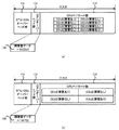
図2に示すように、ODUは、OTU/ODUオーバーヘッド部131と、OPUオーバーヘッド部132と、OPUペイロード部133とを含んでいる。尚、図1に示すODUは、8ビット×256ビットの大きさのデータ群が3824列×4行集合することによって構成されている。
As shown in FIG. 2, the ODU includes an OTU /
OTU/ODUオーバーヘッド部131は、ODUのうちの第1列から第14列(但し、1列の列方向のサイズは8ビット)且つ第1行から第4行(但し、1行の行方向のサイズは256ビット)に相当するデータ部分を占めている。OTU/ODUオーバーヘッド部131には、ODUを制御及び管理するための各種情報が含まれている。一例として、OTU/ODUオーバーヘッド部131には、PM(Path Monitoring:パスモニタリング)や、TCM(Tandem Connection Monitoring:タンデムコネクションモニタリング)や、FTFL(Fault Type & Fault Location reporting channel:フォールトタイプ&フォールト位置報告チャネル)や、EXP(Experimental:エクスペリメンタル)や、GCC(General Communication Channel:ジェネラルコミュニケーションチャネル)や、APS(Automatic Protection Switching coordination channel:自動保護切替コーディネーションチャネル)や、PCC(Protection Communication Control channel:保護コミュニケーション制御チャネル)や、RES(Reserved:リザーブド)エリアが含まれている。
The OTU /
OPUオーバーヘッド部132は、ODUのうちの第15列及び第16列且つ第1行から第4行に相当するデータ部分を占めている。OPUオーバーヘッド部132は、OPUペイロード部133を制御及び管理するための各種情報が含まれている。具体的には、OPUオーバーヘッド部132には、第15列第4行のデータ部分を占めるPSI(Payload Structure Identifier:ペイロード構造識別子)134と、その他のデータ部分を占めるマッピング・連結部(Mapping & Concat. specific)135とが含まれている。
The OPU
PSI134には更に、第0バイトを占めるPT(Payload Type)136と、その他のデータ部分(つまり、第1バイトから第255バイト)を占めるRESエリア137とが含まれている。第1実施形態では、上述した障害数データ138は、PSI134が含むRESエリア137のうちの所定のデータ部分又は任意のデータ部分に含められる。
The
尚、PSI134のデータ構造は、当該PSI134が含まれるODUの種類によって変化する。具体的には、PSI134がLO OPUのCBRマッピングのためのPSIである場合には、PSI134には、図3(a)に示すように、第0バイトを占めるPT136と、第2バイトの第1ビットを占めるOPU−CSFと、その他のデータ部分(第1バイトから第255バイト:但し、第2バイトの第1ビットを除く)を占めるRESエリア137とが含まれている。同様に、PSI134がLO OPUの仮想連結(Virtual Concatenation)のためのPSIである場合には、PSI134には、図3(b)に示すように、第0バイトを占めるPT136と、第1バイトを占めるvcPT(Virtual Concatenated Payload Type)と、第2バイトの第1ビットを占めるOPU−CSFと、その他のデータ部分(第2バイトから第255バイト:但し、第2バイトの第1ビットを除く)を占めるRESエリア137とが含まれている。同様に、PSI134がPT=20となるHO OPU1のためのPSIである場合には、PSI134には、図3(c)に示すように、第0バイトを占めるPT136と、第2バイトから第3バイトを占めるMSI(Multiplex Structure Identifier)と、その他のデータ部分(第1バイト及び第4バイトから第255バイト)を占めるRESエリア137とが含まれている。同様に、PSI134がPT=20となるHO OPU2のためのPSIである場合には、PSI134には、図3(d)に示すように、第0バイトを占めるPT136と、第2バイトから第5バイトを占めるMSIと、その他のデータ部分(第1バイト及び第6バイトから第255バイト)を占めるRESエリア137とが含まれている。同様に、PSI134がPT=21となるHO OPU2のためのPSIである場合には、PSI134には、図3(e)に示すように、第0バイトを占めるPT136と、第2バイトから第9バイトを占めるMSIと、その他のデータ部分(第1バイト及び第10バイトから第255バイト)を占めるRESエリア137とが含まれている。同様に、PSI134がPT=20となるHO OPU3のためのPSIである場合には、PSI134には、図3(f)に示すように、第0バイトを占めるPT136と、第2バイトから第17バイトを占めるMSIと、その他のデータ部分(第1バイト及び第18バイトから第255バイト)を占めるRESエリア137とが含まれている。同様に、PSI134がPT=21となるHO OPU3のためのPSIである場合には、PSI134には、図3(g)に示すように、第0バイトを占めるPT136と、第2バイトから第33バイトを占めるMSIと、その他のデータ部分(第1バイト及び第34バイトから第255バイト)を占めるRESエリア137とが含まれている。同様に、PSI134がPT=21となるHO OPU4のためのPSIである場合には、PSI134には、第0バイトを占めるPT136と、第2バイトから第81バイトを占めるMSIと、図3(h)に示すように、その他のデータ部分(第1バイト及び第82バイトから第255バイト)を占めるRESエリア137とが含まれている。
Note that the data structure of the
以上説明した図3(a)から図3(h)に示すいずれの例においても、障害数データ138は、PSI134中のRESエリア137の所定のデータ部分又は任意のデータ部分に挿入されることが好ましい。
In any of the examples shown in FIGS. 3A to 3H described above, the
続いて、図4を参照して、障害数データ138の具体例について説明する。ここに、図4は、障害数データ138が付加されたODUの具体例を示すデータ構造図である。
Next, a specific example of the
図4(a)に示すように、x=8チャンネルのODU0(つまり、低次のODUn)がODU2(つまり、高次のODUm)に多重化される例について説明する。この場合、ODU多重部112は、ODUフレーム同期部111より出力される8チャンネルのODU0を、ODU2のOPUペイロード部133に多重化する。ここで、多重化される8チャンネルのODU0のうち3チャンネルのODU0に障害が発生しているとする。この場合、アラーム検出部113は、障害が発生している3チャンネルのODU0の夫々を検出する都度、アラームカウント部114に対してアラームを出力する。従って、アラームカウント部114においてカウントされるアラームの数は「3」となる。このため、図4(a)に示す例では、ODU2のOPUオーバーヘッド部132が含むPSI134中のRESエリア137に挿入される障害数データ138は、「3(ODU)」という情報を含んでいる。
As shown in FIG. 4A, an example in which ODU0 (that is, low-order ODUn) of x = 8 channels is multiplexed to ODU2 (that is, high-order ODUm) will be described. In this case, the
一方で、障害数データ138が、ODUnを構成するトリビュータリスロットの単位での障害数を示してもよいことは前述したとおりである。このようなトリビュータリスロットの単位での障害数を示す障害数データ138の例について、図4(b)を参照して説明する。図4(b)に示すように、4チャンネルのODU2(つまり、低次のODU)がODU3(つまり、高次のODU)に多重化される例について説明する。この場合、ODU多重部112は、ODUフレーム同期部111より出力される4チャンネルのODU2を、ODU3のOPUペイロード部133に多重化する。ここで、多重化される4チャンネルのODU2のうちの2チャンネルのODU2に障害が発生しているとする。この場合、アラーム検出部113は、障害が発生しているODU2を検出する都度、アラームカウント部114に対してアラームを出力する。従って、アラームカウント部114においてカウントされるアラームの数は「2」となる。ここで、ITU−T勧告のOTNによれば、ODU2を構成するトリビュータリスロットの数は「8」である。このため、図4(b)に示す例では、ODU2のOPUオーバーヘッド部132が含むPSI134中のRESエリア137に挿入される障害数データ138は、「2×8=16(TS)」という情報を含んでいる。
On the other hand, as described above, the
(1−2)受信装置
続いて、図5を参照して、第1実施形態の受信装置120について説明する。ここに、図5は、第1実施形態の受信装置120の構成の一例を示すブロック図である。(1-2) Receiving Device Subsequently, the receiving
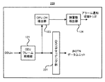
図5に示すように、第1実施形態の受信装置120は、「取得手段」の一具体例に相当するODUフレーム同期部121と、ODU分離部122と、「抽出手段」の一具体例に相当するOPU_OH抽出部123と、「抽出手段」の一具体例に相当する障害数検出部124とを備えている。
As illustrated in FIG. 5, the receiving
ODUフレーム同期部121には、例えば受信装置120に対向する送信装置110から送信される高次のODUmが入力される。ODUフレーム同期部121は、高次のODUmの同期を取った上で、高次のODUmをODU分離部122及びOPU_OH抽出部123に対して出力する。
For example, higher-order ODUm transmitted from the
ODU分離部122は、高次のODUmから、xチャンネルの低次のODUnを分離する。言い換えれば、ODU分離部122は、高次のODUmのOPUペイロード部133に多重化されているxチャンネルの低次のODUnを、個々のODUnに分離する。ODU分離部122は、必要に応じて、分離したxチャンネルの低次のODUnを、当該ODUnに対する各種処理を行う処理部へと出力してもよい。
The
一方で、OPU_OH抽出部123は、高次のODUmのOPUオーバーヘッド部132を抽出する。その後、OPU_OH抽出部123は、抽出したOPUオーバーヘッド部132を、障害数検出部124へと出力する。
On the other hand, the
障害数検出部124は、OPU_OH抽出部123によって抽出されたOPUオーバーヘッド部132から、障害数データ138を抽出する。これにより、障害数検出部124は、ODUフレーム同期部121に入力された高次のODUmに多重化されたxチャンネルの低次のODUnを対象として、障害が発生しているODUnないしはトリビュータリスロットの数を認識することができる。その結果、障害数検出部124は、認識した障害状態に基づいて、伝送路の選択動作ないしは切替動作を制御するアラーム通知切替トリガを出力する。例えば、障害数検出部124は、認識した障害状態に基づいて、適切なないしは高品質な伝送路が使用されるような選択動作ないしは切替動作を行わせしめるアラーム通知切替トリガを出力する。
The failure
以上説明したように、第1実施形態によれば、送信装置110は、高次のODUmのうち低次のODUnが多重化されるOPUペイロード部133とは異なるOPUオーバーヘッド部132に障害数データ138を挿入することができる。従って、高次のODUmを受信する受信装置120は、高次のODUmに含まれる低次のODUnの同期を取ることなく、高次のODUmから障害数データ138を取得することができる。言い換えれば、受信装置120は、高次のODUmの同期を取れば、多重化された低次のODUnの同期を取ることなく、障害数データ138を取得することができる。このため、受信装置120は、高次のODUmに含まれる低次のODUnの同期を取ることなく、多重化された低次のODUnの障害状態を認識することができる。従って、受信装置120は、多重化された低次のODUnの障害状態を認識するために従来必要とされた複数チャンネルの低次のODUnの夫々の同期を取るための複数の同期回路を備えていなくともよい。従って、第1実施形態の送信装置110によれば、受信装置120の回路規模ないしは処理負荷を相対的に低減させながらも、高次のODUmに含まれる低次のODUnの障害状態を受信装置120に対して好適に認識させることができる。
As described above, according to the first embodiment, the
また、第1実施形態の受信装置120によれば、高次のODUmから障害数データ138を抽出することができる。つまり、受信装置120は、高次のODUmの同期を取れば、多重化された低次のODUnの同期を取ることなく、障害数データ138を取得することができる。従って、上述したように、受信装置120は、その回路規模ないしは処理負荷を相対的に低減しつつも、高次のODUmに含まれる低次のODUnの障害状態を好適に認識することができる。
Further, according to the receiving
加えて、第1実施形態によれば、送信装置110は、低次のODUnの単位での障害数を示す障害数データ138を高次のODUmに挿入することができる。このため、受信装置120は、低次のODUnの障害状態を好適に認識することができる。
In addition, according to the first embodiment, the
或いは、第1実施形態によれば、送信装置110は、低次のODUnを更に細分化したトリビュータリスロットの単位での障害数を示す障害数データ138を高次のODUmに挿入することができる。このため、受信装置120は、低次のODUnの障害状態をより一層好適に認識することができる。例えば、障害が発生している2チャンネルのODU1を含む4チャンネルのODU1をODU2に多重化する第1例と、障害が発生している2チャンネルのODU2を含む4チャンネルのODU2をODU3に多重化する第2例を用いて説明する。障害数データ138が低次のODUnの単位での障害数を示す場合には、第1例及び第2例の双方共に、障害数データ138は「2」を示す。一方で、障害数データ138が低次のODUnを構成するトリビュータリスロットの単位での障害数を示す場合には、第1例では障害数データ138は「2×2=4」を示す一方で、第2例では障害数データ138は「2×8=16」を示す。従って、受信装置120は、第1例と比較して、第2例の方がより障害の程度が大きいと認識することができる。
Alternatively, according to the first embodiment, the
尚、上述の説明では、送信装置110及び受信装置120が夫々別個独立の装置として構成される場合の例について説明している。しかしながら、1つの伝送装置が送信装置110及び受信装置120の双方を備えるように構成してもよい。このように構成しても、伝送装置は、上述した各種効果を享受することができる。
In the above description, an example in which the
また、上述の説明では、障害数データ138が、OPUオーバーヘッド部132が含むPSI134中のRESエリア137に挿入される例について説明している。しかしながら、上述した障害数データ138が挿入されるデータ部分は一例であって、PSI134中のRESエリア137以外のデータ部分に挿入されてもよい。但し、高次のODUmに含まれる低次のODUnの同期を取ることなく高次のODUmから障害数データ138を取得するという観点からは、障害数データ138は、高次のODUmのOPUペイロード部133以外のデータ部分に挿入されることが好ましい。或いは、同様の観点からは、障害数データ138は、高次のODUmのOPUペイロード部133のうち低次のODUnが多重化されているデータ部分以外のデータ部分に挿入されてもよい。
Further, in the above description, an example in which the
また、上述の説明では、低次のODUnの障害状態を示す障害数データ138として、障害が発生しているODUn又は障害が発生しているODUnを構成するトリビュータリスロットの数を用いる例について説明している。しかしながら、低次のODUnの障害状態を示す任意の情報(例えば、障害の程度を示す情報や、障害の発生箇所を示す情報や、障害の訂正可能性を示す情報等)を障害数データ138として利用してもよい。
Further, in the above description, an example is described in which the number of tributary slots constituting the ODUn in which the failure has occurred or the ODUn in which the failure has occurred is used as the
(2)第2実施形態
続いて、図6及び図7を参照して、第2実施形態の送信装置210及び受信装置220について説明する。ここに、図6は、第2実施形態の送信装置210の構成の一例を示すブロック図であり、図7は、第2実施形態の受信装置220の構成の一例を示すブロック図である。尚、上述した第1実施形態の送信装置110及び受信装置120が備える各種構成と同一の構成については、同一の参照符号を付してその詳細な説明については省略する。(2) Second Embodiment Subsequently, a
図6に示すように、第2実施形態の送信装置210は、「生成手段」の一具体例に相当するODUマッピング部211と、アラーム検出部113と、アラームカウント部114と、OPU_OH挿入部115とを備えている。
As illustrated in FIG. 6, the
ODUマッピング部211には、OTNに準拠したデータユニット(つまり、ODU)以外のデータユニット(以降“非OTNデータユニット”と称する)が入力される。非
OTNデータユニットとして、例えば、10GbE(Giga bit Ethernet)やGbEにおけるイーサネット(登録商標)フレームやSDH(Synchronous Digital Hierarchy)におけるSTM(Synchronous Transport Module)フレームやSONET(Synchronous Optical Network)におけるSTS(Synchronous Transport Signal)フレームないしはOC(Optical Carrier)信号等が一例としてあげられる。尚、非OTNデータユニットは、「第2データユニット」の一具体例に相当する。ODUマッピング部211は、非OTNデータユニットを、OTN準拠のデータユニットであるODUmのOPUペイロード部133にマッピングする。ODUマッピング部211は、非OTNデータユニットがマッピングされたODUmを、OPU_OH挿入部115に対して出力する。The
一方で、アラーム検出部113は、非OTNデータユニットにおける障害の発生の有無を検出する。第2実施形態では、アラーム検出部113は、非OTNデータユニットに障害が発生している場合には、障害が検出されたことを示すアラームをアラームカウント部114に出力する。一方で、アラーム検出部113は、非OTNデータユニットに障害が発生していない場合には、障害が検出されたことを示すアラームをアラームカウント部114に出力しない。
On the other hand, the
アラームカウント部114は、アラーム検出部113から出力されるアラームの数をカウントする。アラームカウント部114は、非OTNデータユニットがマッピングされる周期(言い換えれば、ODUmが生成される周期)に同期して、カウントしたアラームの数をOPU_OH挿入部115に出力する。
The
OPU_OH挿入部115は、ODUmのOPUオーバーヘッド部132の所定のデータ部分(例えば、上述したPSI134中のRESエリア137)に、アラームカウント部114から出力されるアラームの数を示す障害数データ138を挿入する。つまり、OPU_OH挿入部115は、ODUmのOPUオーバーヘッド部132の所定のデータ部分に、ODUmにマッピングされた非OTNデータユニットに障害が発生しているか否かを示す障害数データ138を挿入する。尚、第2実施形態においては、非OTNデータユニットに障害が発生している場合には、障害数データ138は「1」を示す。一方で、非OTNデータユニットに障害が発生していない場合には、障害数データ138は「0」を示す。
The
図7に示すように、第2実施形態の受信装置220は、「取得手段」の一具体例に相当するODUフレーム同期部121と、ODUデマッピング部221と、「抽出手段」の一具体例に相当するOPU_OH抽出部123と、「抽出手段」の一具体例に相当する障害数検出部124とを備えている。
As illustrated in FIG. 7, the receiving
ODUフレーム同期部121には、例えば受信装置220に対向する送信装置210から送信されるODUmが入力される。ODUフレーム同期部121は、ODUmの同期を取った上で、ODUmをODUデマッピング部221及びOPU_OH抽出部123に対して出力する。
For example, the ODUm transmitted from the
ODUデマッピング部221は、ODUmから、非OTNデータユニットを抽出する。ODUデマッピング部221は、必要に応じて、抽出した非OTNデータユニットを、当該非OTNデータユニットに対する各種処理を行う処理部へと出力してもよい。
The
尚、OPU_OH抽出部123及び障害数検出部124は、第1実施形態と同様の動作を行う。つまり、OPU_OH抽出部123は、ODUmのOPUオーバーヘッド部132を抽出し、障害数検出部124は、OPU_OH抽出部123によって抽出されたOPUオーバーヘッド部132から、障害数データ138を抽出する。
The
以上説明したように、第2実施形態によれば、OTNに準拠したデータユニット以外の非OTNデータユニットをOTNに準拠したデータユニットであるODUmにマッピングする場合であっても、上述した第1実施形態の送信装置110又は受信装置120が享受する各種効果と同様の効果を享受することができる。つまり、受信装置220は、ODUmに含まれる非OTNデータユニットの同期を取ることなく、ODUmから障害数データ138を取得することができる。従って、受信装置220は、マッピングされた非OTNデータユニットの障害状態を認識するために従来必要とされた非OTNデータユニットの同期を取るための同期回路を備えていなくともよい。従って、第2実施形態によれば、第1実施形態と同様に、受信装置220の回路規模ないしは処理負荷を相対的に低減させながらも、ODUmにマッピングされた非OTNデータユニットの障害状態を受信装置220に対して好適に認識させることができる。
As described above, according to the second embodiment, even when a non-OTN data unit other than an OTN-compliant data unit is mapped to an ODUm that is a data unit compliant with the OTN, the first implementation described above. The effect similar to the various effects which the
(3)第3実施形態
続いて、図8及び図9を参照して、第3実施形態の送信装置310及び受信装置320について説明する。ここに、図8は、第3実施形態の送信装置310の構成の一例を示すブロック図であり、図9は、第3実施形態の受信装置320の構成の一例を示すブロック図である。尚、上述した第1実施形態の送信装置110及び受信装置120並びに第2実施形態の送信装置210及び受信装置220が備える各種構成と同一の構成については、同一の参照符号を付してその詳細な説明については省略する。(3) Third Embodiment Next, a
図8に示すように、第3実施形態の送信装置310は、1チャンネルの非OTNデータユニットをODUmにマッピングする第2実施形態の送信装置210と比較して、xチャンネルの非OTNデータユニットをODUmにマッピングするという点で異なっている。具体的には、第3実施形態の送信装置310は、「生成手段」の一具体例に相当するx個のODUマッピング部211と、x個のOPU_OH挿入部115_1と、「生成手段」の一具体例に相当するODU多重部112と、アラーム検出部113と、アラームカウント部114と、「付加手段」の一具体例に相当するOPU_OH挿入部115_2とを備えている。
As illustrated in FIG. 8, the
x個のODUマッピング部211の夫々には、xチャンネルの非OTNデータユニットのうちの対応する一チャンネルの非OTNデータユニットが入力される。x個のODUマッピング部211の夫々は、対応する一チャンネルの非OTNデータユニットを、OTN準拠のデータユニットであるODUnのOPUペイロード部133にマッピングする。x個のODUマッピング部211の夫々は、対応する一チャンネルの非OTNデータユニットがマッピングされたODUnを、x個のOPU_OH挿入部115_1のうちの対応する一つのOPU_OH挿入部115_1に対して出力する。
A corresponding one-channel non-OTN data unit among the x-channel non-OTN data units is input to each of the x
x個のOPU_OH挿入部115_1の夫々は、対応する一つのODUマッピング部211より出力されるODUnのOPUオーバーヘッド部132に対して、各種情報を挿入する。その後、x個のOPU_OH挿入部115_1の夫々は、OPUオーバーヘッド部132に各種情報が挿入されたODUnを、ODU多重部112に対して出力する。従って、ODU多重部112には、xチャンネルのODUnが入力される。
Each of the x OPU_OH insertion units 115_1 inserts various types of information into the OPU
ODU多重部112は、xチャンネルの低次のODUnを多重化する。具体的には、ODU多重部112は、xチャンネルの低次のODUnを高次のODUmのOPUペイロード部133に多重化する。ODU多重部112は、xチャンネルの低次のODUnがOPUペイロード部133に多重化された高次のODUmを、OPU_OH挿入部115に対して出力する。
The
一方で、アラーム検出部113には、xチャンネルの非OTNデータユニットが入力される。アラーム検出部113は、非OTNデータユニットにおける障害の発生の有無を検出する。第3実施形態では、アラーム検出部113は、障害が発生している非OTNデータユニットが検出される都度、障害が検出されたことを示すアラームをアラームカウント部114に出力する。
On the other hand, the
アラームカウント部114は、アラーム検出部113から出力されるアラームの数をカウントする。アラームカウント部114は、xチャンネルの非OTNデータユニットがマッピングされる周期(言い換えれば、ODUmが生成される周期)に同期して、カウントしたアラームの数をOPU_OH挿入部115_2に出力する。
The
OPU_OH挿入部115_2は、ODUmのOPUオーバーヘッド部132の所定のデータ部分(例えば、上述したPSI134中のRESエリア137)に、アラームカウント部114から出力されるアラームの数を示す障害数データ138を挿入する。つまり、OPU_OH挿入部115_2は、ODUmのOPUオーバーヘッド部132の所定のデータ部分に、ODUmにマッピングされたxチャンネルの非OTNデータユニットのうちの障害が発生している非OTNデータユニットの数を示す障害数データ138を挿入する。
The OPU_OH insertion unit 115_2 inserts
図9に示すように、第3実施形態の受信装置320は、ODUmにマッピングされた1チャンネルの非OTNデータユニットを取得する第2実施形態の受信装置220と比較して、ODUmにマッピングされたxチャンネルの非OTNデータユニットを取得するという点で異なっている。具体的には、第3実施形態の受信装置320は、「取得手段」の一具体例に相当するODUフレーム同期部121と、ODU分離部122と、x個のOPU_OH抽出部123_2と、ODUデマッピング部221と、「取得手段」の一具体例に相当するOPU_OH抽出部123_1と、「取得手段」の一具体例に相当する障害数検出部124とを備えている。
As illustrated in FIG. 9, the receiving
ODUフレーム同期部121には、例えば受信装置320に対向する送信装置310から送信されるODUmが入力される。ODUフレーム同期部121は、ODUmの同期を取った上で、ODUmをODU分離部122及びOPU_OH抽出部123_1に対して出力する。
For example, ODUm transmitted from the
ODU分離部122は、高次のODUmから、xチャンネルの低次のODUnを分離する。その後、ODU分離部122は、xチャンネルの低次のODUnの夫々を、x個のOPU_OH抽出部123_2のうちの対応する一つのOPU_OH抽出部123に対して出力する。
The
x個のOPU_OH抽出部123_2の夫々は、xチャンネルの低次のODUnのうち対応する一チャンネルのODUnからOPUオーバーヘッド部132を抽出する。その後、x個のOPU_OH抽出部123_2の夫々は、xチャンネルの低次のODUnのうち対応する一チャンネルのODUnをODUデマッピング部221に対して出力する。
Each of the x OPU_OH extraction units 123_2 extracts the OPU
ODUデマッピング部221は、xチャンネルのODUnの夫々から、非OTNデータユニットを抽出する。つまり、ODUデマッピング部221は、xチャンネルのODUnから、xチャンネルの非OTNデータユニットを抽出する。ODUデマッピング部221は、必要に応じて、抽出した非OTNデータユニットを、当該非OTNデータユニットに対する各種処理を行う処理部へと出力してもよい。
The
尚、OPU_OH抽出部123_1及び障害数検出部124は、第1実施形態と同様の動作を行う。つまり、OPU_OH抽出部123_1は、ODUmのOPUオーバーヘッド部132を抽出し、障害数検出部124は、OPU_OH抽出部123_1によって抽出されたOPUオーバーヘッド部132から、障害数データ138を抽出する。
The OPU_OH extraction unit 123_1 and the failure
以上説明したように、第3実施形態によれば、複数チャンネルの非OTNデータユニットをODUmにマッピングする場合であっても、上述した第1実施形態の送信装置110又は受信装置120が享受する各種効果と同様の効果を享受することができる。つまり、受信装置320は、ODUmに含まれる複数チャンネルの非OTNデータユニットの夫々の同期を取ることなく、ODUmから障害数データ138を取得することができる。このため、受信装置320は、ODUmに含まれる複数の非OTNデータユニットの同期を取ることなく、マッピングされた複数チャンネルの非OTNデータユニットの障害状態を認識することができる。従って、受信装置320は、マッピングされた複数チャンネルの非OTNデータユニットの障害状態を認識するために従来必要とされた複数チャンネルの非OTNデータユニットの同期を取るための複数の同期回路を備えていなくともよい。従って、第3実施形態によれば、第1実施形態と同様に、受信装置320の回路規模ないしは処理負荷を相対的に低減させながらも、ODUmにマッピングされた複数チャンネルの非OTNデータユニットの障害状態を受信装置320に対して好適に認識させることができる。
As described above, according to the third embodiment, even when a plurality of channels of non-OTN data units are mapped to ODUm, the various types of information received by the
(4)第4実施形態
続いて、図10を参照して、第4実施形態の送信装置410について説明する。ここに、図10は、第4実施形態の送信装置410の構成の一例を示すブロック図である。尚、上述した第1実施形態の送信装置110及び受信装置120から第3実施形態の送信装置310及び受信装置320が備える各種構成と同一の構成については、同一の参照符号を付してその詳細な説明については省略する。(4) Fourth Embodiment Next, a
図10に示すように、第4実施形態の送信装置410は、非OTNデータユニットを低次のODUnにマッピングする前に検出されたアラームに基づいて高次のODUmに障害数データ138を挿入する第3実施形態の送信装置310と比較して、非OTNデータユニットを低次のODUnへマッピングした後に当該低次のODUnから抽出されるOPUオーバーヘッド部132に基づいて高次のODUmに障害数データ138を挿入するという点で異なっている。具体的には、第4実施形態の送信装置410は、「生成手段」の一具体例に相当するx個のODUマッピング部211と、x個のOPU_OH挿入部115_1と、「生成手段」の一具体例に相当するODU多重部112と、アラーム検出部113と、OPU_OH抽出部123と、アラームカウント部114と、「付加手段」の一具体例に相当するOPU_OH挿入部115_2とを備えている。
As shown in FIG. 10, the
x個のODUマッピング部211の夫々は、対応する一チャンネルの非OTNデータユニットを、OTN準拠のデータユニットであるODUnのOPUペイロード部133にマッピングすると共に、対応する一つのOPU_OH挿入部115_1に対して出力する。
Each of the x
一方で、アラーム検出部113は、非OTNデータユニットにおける障害の発生の有無を検出する。第4実施形態では、アラーム検出部113は、障害が発生している非OTNデータユニットが検出される都度、障害が検出されたことを示すアラームを、x個のOPU_OH挿入部115_1のうちの対応する一つのOPU_OH挿入部115_1に対して出力する。
On the other hand, the
x個のOPU_OH挿入部115_1の夫々は、アラーム検出部113から出力されるアラームに基づいて、対応する一チャンネルの非OTNデータユニットに障害が発生しているか否かを示す障害数データ138を対応する一チャンネルのODUnのOPUオーバーヘッド部132に挿入する。その後、x個のOPU_OH挿入部115_1の夫々は、OPUオーバーヘッド部132に各種情報が挿入されたODUnを、ODU多重部112及びOPU_OH抽出部123に対して出力する。
Each of the x OPU_OH insertion units 115_1 corresponds to the
ODU多重部112は、xチャンネルの低次のODUnを多重化する。ODU多重部112は、xチャンネルの低次のODUnがOPUペイロード部133に多重化された高次のODUmを、OPU_OH挿入部115_2に対して出力する。
The
一方で、OPU_OH抽出部123は、xチャンネルの低次のODUnの夫々からOPUオーバーヘッド部132を抽出する。その後、OPU_OH抽出部123は、抽出したx個のOPUオーバーヘッド部132をアラームカウント部114に対して出力する。
On the other hand, the
アラームカウント部114は、OPU_OH抽出部123から出力されるx個のOPUオーバーヘッド部132に基づいて、xチャンネルの非OTNデータユニットのうちの障害が発生している非OTNデータユニットの数をOPU_OH挿入部115_2に対して出力する。
Based on the x OPU
OPU_OH挿入部115_2は、ODUmのOPUオーバーヘッド部132の所定のデータ部分(例えば、上述したPSI134中のRESエリア137)に、アラームカウント部114から出力される障害の数を示す障害数データ138を挿入する。つまり、OPU_OH挿入部115_2は、ODUmのOPUオーバーヘッド部132の所定のデータ部分に、ODUmにマッピングされたxチャンネルの非OTNデータユニットのうちの障害が発生している非OTNデータユニットの数を示す障害数データ138を挿入する。この結果、第4実施形態の送信装置410は、第3実施形態の送信装置310が生成するODUmと同様のODUmを生成することができる。
The OPU_OH insertion unit 115_2 inserts
以上説明したように、第4実施形態の送信装置410によれば、第3実施形態の送信装置310が享受する各種効果と同様の効果を好適に享受することができる。加えて、第4実施形態の送信装置410によれば、x個のODUマッピング部211、x個のOPU_OH挿入部115_1及びアラーム検出部113を含む処理ブロックと、ODU多重部112、OPU_OH抽出部123、アラームカウント部114及びOPU_OH挿入部115_2を含む処理ブロックとが物理的に又は論理的に分離されている場合であっても、上述した各種効果を享受することができる。
As explained above, according to the
(5)第5実施形態
続いて、図11から図13を参照して、第5実施形態の送信装置510及び受信装置520について説明する。ここに、図11は、第5実施形態の送信装置510の構成の一例を示すブロック図であり、図12は、障害数データ138が付加されたODUの具体例を示すデータ構造図であり、図13は、第5実施形態の受信装置520の構成の一例を示すブロック図である。尚、上述した第1実施形態の送信装置110及び受信装置120から第4実施形態の送信装置410及び受信装置420が備える各種構成と同一の構成については、同一の参照符号を付してその詳細な説明については省略する。(5) Fifth Embodiment Next, a
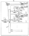
図11に示すように、第5実施形態の送信装置510は、ODUの1段の多重化を行う第1実施形態の送信装置110と比較して、ODUの2段の(或いは、3段以上の複数段の)多重化を行うという点で異なっている。具体的には、第5実施形態の送信装置510は、ODUフレーム同期部111と、「生成手段」の一具体例に相当するODU多重部112_1と、アラーム検出部113と、アラームカウント部114_1と、「付加手段」の一具体例に相当するOPU_OH挿入部115_1とを夫々が備えるx個の送信処理ブロック511を備えている。また、第5実施形態の送信装置510は更に、「生成手段」の一具体例に相当するODU多重部112_2と、アラームカウント部114_2と、「付加手段」の一具体例に相当するOPU_OH挿入部115_2とを備えている。
As illustrated in FIG. 11, the
x個の送信処理ブロック511の夫々は、第1実施形態の送信装置110と同様の構成を有している。
Each of the x transmission processing blocks 511 has the same configuration as that of the
具体的には、x個の送信処理ブロック511の夫々が備えるODUフレーム同期部111には、y(但し、yは1以上の整数)チャンネルの低次のODUk(但し、kはk<nを満たす整数)が入力される。尚、低次のODUkは、「第3データユニット」の一具体例に相当する。ODUフレーム同期部111は、yチャンネルの低次のODUkの同期を取った上で、yチャンネルの低次のODUkをODU多重部112_1及びアラーム検出部113に対して出力する。
Specifically, the ODU
x個の送信処理ブロック511の夫々が備えるODU多重部112_1は、yチャンネルの低次のODUkを多重化する。具体的には、ODU多重部112_1は、yチャンネルの低次のODUkを、ODUkよりも高次のODUnのOPUペイロード部133に多重化する。ODU多重部112_1は、yチャンネルの低次のODUkがOPUペイロード部133に多重化された高次のODUnを、OPU_OH挿入部115_1に対して出力する。
The ODU multiplexing unit 112_1 included in each of the x transmission processing blocks 511 multiplexes the low-order ODUk of the y channel. Specifically, the ODU multiplexing unit 112_1 multiplexes the lower-order ODUk of the y channel into the
一方で、x個の送信処理ブロック511の夫々が備えるアラーム検出部113は、yチャンネルの低次のODUkの夫々における障害の発生の有無を検出する。アラーム検出部113は、障害が発生している低次のODUkが検出される都度、障害が検出されたことを示すアラームをアラームカウント部114_1に出力する。
On the other hand, the
x個の送信処理ブロック511の夫々が備えるアラームカウント部114_1は、アラーム検出部113から出力されるアラームの数をカウントする。アラームカウント部114_1は、ODUkが多重化される周期(言い換えれば、高次のODUnが生成される周期)に同期して、カウントしたアラームの数をOPU_OH挿入部115_1及びアラームカウント部114_2に出力する。
The alarm count unit 114_1 included in each of the x transmission processing blocks 511 counts the number of alarms output from the
x個の送信処理ブロック511の夫々が備えるOPU_OH挿入部115_1は、ODU多重部112_1より出力される高次のODUnのOPUオーバーヘッド部132に対して、各種情報を挿入する。第5実施形態では、OPU_OH挿入部115_1は、高次のODUnのOPUオーバーヘッド部132の所定のデータ部分(例えば、上述したPSI134中のRESエリア137)に、アラームカウント部114_1から出力されるアラームの数を示す障害数データ138を挿入する。つまり、OPU_OH挿入部115_1は、高次のODUnのOPUオーバーヘッド部132の所定のデータ部分に、高次のODUnに多重化されたyチャンネルの低次のODUkのうちの障害が発生しているODUkの数(或いは、障害が発生しているODUkを構成するトリビュータリスロットの数)を示す障害数データ138を挿入する。その後、OPU_OH挿入部115_1は、高次のODUnをODU多重部112_2に対して出力する。従って、ODU多重部112_2には、nチャンネルの高次のODUnが入力される。
The OPU_OH insertion unit 115_1 included in each of the x transmission processing blocks 511 inserts various types of information into the OPU
ODU多重部112_2は、xチャンネルの高次のODUnを多重化する。具体的には、ODU多重部112_2は、xチャンネルの高次のODUnを更に高次のODUmのOPUペイロード部133に多重化する。ODU多重部112_2は、xチャンネルの高次のODUnがOPUペイロード部133に多重化されたより高次のODUmを、OPU_OH挿入部115_2に対して出力する。
The ODU multiplexing unit 112_2 multiplexes high-order ODUn of the x channel. Specifically, the ODU multiplexing unit 112_2 multiplexes the higher-order ODUn of the x channel into the
一方で、アラームカウント部114_2は、アラームカウント部114_1から出力されるアラームの数の総数をOPU_OH挿入部115_2に出力する。つまり、アラームカウント部114_2は、x個の送信処理ブロック511が備えるx個のアラームカウント部114によりカウントされたアラームの数の総数をOPU_OH挿入部115_2に出力する。
On the other hand, the alarm count unit 114_2 outputs the total number of alarms output from the alarm count unit 114_1 to the OPU_OH insertion unit 115_2. That is, the alarm count unit 114_2 outputs the total number of alarms counted by the x
OPU_OH挿入部115_2は、ODU多重部112_2より出力されるより高次のODUmのOPUオーバーヘッド部132の所定のデータ部分(例えば、上述したPSI134中のRESエリア137)に対して、アラームカウント部114_2から出力されるアラームの数を示す障害数データ138を挿入する。つまり、OPU_OH挿入部115_2は、より高次のODUmのOPUオーバーヘッド部132の所定のデータ部分に、より高次のODUmに多重化されたxチャンネルの高次のODUnに更に多重化されているx×yチャンネルの低次のODUkのうちの障害が発生しているODUkの数(或いは、障害が発生しているODUkを構成するトリビュータリスロットの数)を示す障害数データ138を挿入する。
The OPU_OH insertion unit 115_2 performs the alarm count unit 114_2 on the predetermined data portion (for example, the
第5実施形態の障害数データ138の具体例について図12を参照して説明する。図12に示すように、y=8チャンネルのODU0(つまり、低次のODUk)がODU2(つまり、高次のODUn)に多重化され且つx=2チャンネルのODU2がODU4(つまり、より高次のODUm)に多重化される例について説明する。この場合、2つの送信処理ブロック511の夫々が備えるODU多重部112_1は、ODUフレーム同期部111より出力される8チャンネルのODU0を、ODU2のペイロード部133に多重化する。ここで、図12の相対的に左側に示す第1のODU2に多重化される8チャンネルのODU0のうち4チャンネルのODU0に障害が発生しており且つ図12の相対的に右側に示す第2のODU2に多重化される8チャンネルのODU0のうち2チャンネルのODU0に障害が発生しているとする。この場合、第1のODU2を生成するための送信処理ブロック511が備えるアラーム検出部113は、障害が発生している4チャンネルのODU0の夫々を検出する都度、アラームカウント部114_1に対してアラームを出力する。従って、第1のODU2を生成するための送信処理ブロック511が備えるアラームカウント部114_1においてカウントされるアラームの数は「4」となる。このため、図12に示す例では、第1のODU2のOPUオーバーヘッド部132が含むPSI134中のRESエリア137に挿入される障害数データ138は、「4(ODU)」という情報を含んでいる。同様に、第2のODU2を生成するための送信処理ブロック511が備えるアラーム検出部113は、障害が発生している2チャンネルのODU0の夫々を検出する都度、アラームカウント部114_1に対してアラームを出力する。従って、第2のODU2を生成するための送信処理ブロック511が備えるアラームカウント部114_1においてカウントされるアラームの数は「2」となる。このため、図12に示す例では、第2のODU2のOPUオーバーヘッド部132が含むPSI134中のRESエリア137に挿入される障害数データ138は、「2(ODU)」という情報を含んでいる。
A specific example of the
加えて、第5実施形態では、従って、第1のODU2を生成するための送信処理ブロック511が備えるアラームカウント部114_1によりカウントされるアラームの数「4」と第2のODU2を生成するための送信処理ブロック511が備えるアラームカウント部114_1によりカウントされるアラームの数「2」は、更にアラームカウント部114_2に対して出力される。従って、アラームカウント部114_2においてカウントされるアラームの数の総数は「6」となる。このため、図12に示す例では、ODU4のOPUオーバーヘッド部132が含むPSI134中のRESエリア137に挿入される障害数データ138は、「6(ODU)」という情報を含んでいる。
In addition, in the fifth embodiment, therefore, the number of alarms “4” counted by the alarm count unit 114_1 included in the
続いて、第5実施形態の受信装置520について説明する。図13に示すように、第5実施形態の受信装置520は、1段の多重化が行われたODUの分離を行う第1実施形態の受信装置120と比較して、2段の(或いは、3段以上の複数段の)多重化が行われたODUの分離を行うという点で異なっている。具体的には、第5実施形態の受信装置520は、「取得手段」の一具体例に相当するODUフレーム同期部121_1と、「抽出手段」の一具体例に相当するOPU_OH抽出部123_1と、「抽出手段」の一具体例に相当する障害数検出部124_1と、ODU分離部122_1と、x個の受信処理ブロック521とを備えている。x個の受信ブロック521の夫々は、「取得手段」の一具体例に相当するODUフレーム同期部121_2と、ODU分離部122_2と、「抽出手段」の一具体例に相当するOPU_OH抽出部123_2と、「抽出手段」の一具体例に相当する障害数検出部124_2とを備えている。
Subsequently, the receiving
ODUフレーム同期部121_1には、例えば受信装置520に対向する送信装置510から送信される高次のODUmが入力される。ODUフレーム同期部121_1は、高次のODUmの同期を取った上で、高次のODUmをODU分離部122_1及びOPU_OH抽出部123_1に対して出力する。
For example, higher-order ODUm transmitted from the
OPU_OH抽出部123_1は、高次のODUmのOPUオーバーヘッド部132を抽出する。その後、OPU_OH抽出部123_1は、抽出したOPUオーバーヘッド部132を、障害数検出部124_1へと出力する。
The OPU_OH extraction unit 123_1 extracts the OPU
障害数検出部124_1は、OPU_OH抽出部123_1によって抽出されたOPUオーバーヘッド部132から、障害数データ138を抽出する。これにより、障害数検出部124_1は、ODUフレーム同期部121に入力された高次のODUmに多重化されたxチャンネルの低次のODUnに更に多重化されているx×yチャンネルのより低次のODUkを対象として、障害が発生しているODUkないしはトリビュータリスロットの数を認識することができる。その結果、障害数検出部124_1は、認識した障害状態に基づいて、伝送路の選択動作ないしは切替動作を制御するアラーム通知切替トリガを出力する。
The failure number detection unit 124_1 extracts the
一方で、ODU分離部122は、高次のODUmから、xチャンネルの低次のODUnを分離する。その後、ODU分離部122は、分離したxチャンネルの低次のODUnの夫々を、x個の受信処理ブロック521のうちの対応する一つの受信処理ブロック521が備えるODUフレーム同期部121_2に対して出力してもよい。
On the other hand, the
x個の受信処理ブロック521の夫々が備えるODUフレーム同期部121_2には、xチャンネルの低次のODUnのうちの対応する一チャンネルのODUnが入力される。ODUフレーム同期部121_2は、低次のODUnの同期を取った上で、低次のODUnをODU分離部122_2及びOPU_OH抽出部123_2に対して出力する。 The ODU frame synchronization unit 121_2 included in each of the x reception processing blocks 521 receives the corresponding one channel ODUn among the low-order ODUn of the x channel. The ODU frame synchronization unit 121_2 outputs the low-order ODUn to the ODU separation unit 122_2 and the OPU_OH extraction unit 123_2 after synchronizing the low-order ODUn.
x個の受信処理ブロック521の夫々が備えるODU分離部122_2は、低次のODUnから、yチャンネルのより低次のODUkを分離する。ODU分離部122_2は、必要に応じて、分離したyチャンネルのより低次のODUkを、当該ODUkに対する各種処理を行う処理部へと出力してもよい。 The ODU separation unit 122_2 included in each of the x reception processing blocks 521 separates the lower order ODUk of the y channel from the lower order ODUn. The ODU separation unit 122_2 may output a lower-order ODUk of the separated y channel to a processing unit that performs various processes on the ODUk, as necessary.
一方で、x個の受信処理ブロック521の夫々が備えるOPU_OH抽出部123_2は、低次のODUnのOPUオーバーヘッド部132を抽出する。その後、OPU_OH抽出部123_2は、抽出したOPUオーバーヘッド部132を、障害数検出部124_2へと出力する。
On the other hand, the OPU_OH extraction unit 123_2 included in each of the x reception processing blocks 521 extracts the OPU
x個の受信処理ブロック521の夫々が備える障害数検出部124_2は、OPU_OH抽出部123_2によって抽出されたOPUオーバーヘッド部132から、障害数データ138を抽出する。これにより、障害数検出部124_2は、xチャンネルの低次のODUnのうちの対応する一チャンネルのODUnに多重化されたyチャンネルのより低次のODUkを対象として、障害が発生しているODUkないしはトリビュータリスロットの数を認識することができる。その結果、障害数検出部124は、認識した障害状態に基づいて、伝送路の選択動作ないしは切替動作を制御するアラーム通知切替トリガを出力する。
The failure number detection unit 124_2 included in each of the x reception processing blocks 521 extracts the
以上、説明したように、第5実施形態によれば、ODUの複数段の多重化が行われている場合であっても、最も高次のODUmの同期をとれば、当該ODUmに多重化されている最も低次のODUkの障害状態を認識することができる。従って、第5実施形態によれば、上述した各種効果を好適に享受することができる。 As described above, according to the fifth embodiment, even when a plurality of stages of ODUs are multiplexed, if the highest order ODUm is synchronized, it is multiplexed to the ODUm. It is possible to recognize the failure state of the lowest order ODUk. Therefore, according to the fifth embodiment, the various effects described above can be suitably enjoyed.
尚、図11から図13に示す例では、ODUの2段の多重化が行われる例について説明している。しかしながら、ODUの3段以上の多重化が行われる場合であっても、送信処理ブロック511ないしは受信処理ブロック521を多段に接続することで、上述した各種効果を好適に享受することができる。具体的には、送信装置510であれば、OPU_OH挿入部115_1から出力されるODUnないしはOPU_OH挿入部115_2から出力されるODUmが、ODUの多重化の数に応じて新たに設けられる多段の送信処理ブロック511に順次入力されるように構成すれば、上述した動作と同様の動作を行うことができると共に上述した各種効果を享受することができる。同様に、受信装置520であれば、ODU分離部122_1から出力されるODUnないしはODU分離部122_2から出力されるODUkの夫々が、ODUの多重化の数に応じて新たに設けられる多段の受信処理ブロック521に順次入力されるように構成すれば、上述した動作と同様の動作を行うことができると共に上述した各種効果を享受することができる。
In the examples shown in FIGS. 11 to 13, an example in which two-stage multiplexing of ODU is performed is described. However, even when the ODU is multiplexed in three or more stages, the above-described various effects can be suitably enjoyed by connecting the
(6)第6実施形態
続いて、図14から図16を参照して、第6実施形態の送信装置610及び受信装置620について説明する。ここに、図14は、第6実施形態の送信装置610の構成の一例を示すブロック図であり、図15は、障害数データ138が付加されたODUの具体例を示すデータ構造図であり、図16は、第6実施形態の受信装置620の構成の一例を示すブロック図である。尚、上述した第1実施形態の送信装置110及び受信装置120から第5実施形態の送信装置510及び受信装置520が備える各種構成と同一の構成については、同一の参照符号を付してその詳細な説明については省略する。(6) Sixth Embodiment Next, a
図14に示すように、第6実施形態の送信装置610は、ODUkが多重化されたODUnを更にODUmに多重化する第5実施形態の送信装置510と比較して、ODUkが多重化されたODUn及びODUkが多重化されていないODUnを更にODUmに多重化するという点で異なっている。具体的には、第6実施形態の送信装置610は、第5実施形態の送信装置510と比較して、x個の送信処理ブロック511のうちのz(但し、zは1≦z≦xを満たす整数)個の送信処理ブロック511が、ODUフレーム同期部111及びアラーム検出部を夫々が備えるz個の送信処理ブロック611に置き換えられているという点で異なっている。
As illustrated in FIG. 14, the
z個の送信処理ブロック611の夫々が備えるODUフレーム同期部111には、yチャンネルの低次のODUkに代えて、ODUnが直接入力される。ODUフレーム同期部111は、ODUnの同期を取った上で、ODUnをODU多重部112_2及びアラーム検出部113に対して出力する。
Instead of the low-order ODUk of the y channel, ODUn is directly input to the ODU
z個の送信処理ブロック611の夫々が備えるアラーム検出部113は、yチャンネルの低次のODUkに換えて、ODUnにおける障害の発生の有無を検出する。アラーム検出部113は、障害が発生しているODUnが検出される都度、障害が検出されたことを示すアラームをアラームカウント部114_2に出力する。
The
一方で、x−z個の送信処理ブロック511は、第5実施形態と同様の動作を行う。その結果、ODU多重部112_2には、x−z個の送信処理ブロック511から出力されるx−zチャンネルのODUn(つまり、夫々にyチャンネルのODUkが多重化されたx−zチャンネルのODUn)及びz個の送信処理ブロック611から出力されるzチャンネルのODUnが入力される。以降の動作(つまり、ODU多重部112_2、アラームカウント部114_2及びOPU_OH挿入部115_2の夫々の動作)は、第5実施形態と同様に行われる。 On the other hand, the xz transmission processing blocks 511 perform the same operation as in the fifth embodiment. As a result, in the ODU multiplexing unit 112_2, the xz channel ODUn output from the xz transmission processing blocks 511 (that is, the xz channel ODUn each obtained by multiplexing the y channel ODUk). The z channel ODUn output from the z transmission processing blocks 611 is input. Subsequent operations (that is, operations of the ODU multiplexing unit 112_2, the alarm count unit 114_2, and the OPU_OH insertion unit 115_2) are performed in the same manner as in the fifth embodiment.
第6実施形態の障害数データ138の具体例について図15を参照して説明する。図15に示すように、y=8チャンネルのODU0が多重化された1チャンネルの第1のODU2及びODU0が多重化されていないz=4チャンネルの第1のODU2を含むx=5チャンネルのODU2がODU4に多重化される例について説明する。この場合、1つの送信処理ブロック511が備えるODU多重部112_1は、ODUフレーム同期部111より出力される8チャンネルのODU0を、第1のODU2のOPUペイロード部133に多重化する。ここで、第1のODU2に多重化される8チャンネルのODU0のうち4チャンネルのODU0に障害が発生しているとする。この場合、第1のODU2を生成するための送信処理ブロック511が備えるアラーム検出部113は、障害が発生している4チャンネルのODU0の夫々を検出する都度、アラームカウント部114_1に対してアラームを出力する。従って、第1のODU2を生成するための送信処理ブロック511が備えるアラームカウント部114_1においてカウントされるアラームの数は「4」となる。このため、図15に示す例では、第1のODU2のOPUオーバーヘッド部132が含むPSI134中のRESエリア137に挿入される障害数データ138は、「4(ODU)」という情報を含んでいる。
A specific example of the
一方で、4チャンネルの第2のODU2のうち2チャンネルのODU2に障害が発生しているとする。この場合、4チャンネルの第2のODU2に対応する4つの送信処理ブロック611のうちの2つの送信処理ブロック611が備えるアラーム検出部113が、アラームカウント部114_2に対してアラームを出力する。従って、アラームカウント部114_2には、第1のODU2を生成するための送信処理ブロック511が備えるアラームカウント部114_1によりカウントされるアラームの数「4」と、4チャンネルの第2のODU2に対応する4つの送信処理ブロック611のうちの2つの送信処理ブロック611が備えるアラーム検出部113によりカウントされるアラームの数「2」が出力される。このため、図15に示す例では、ODU4のOPUオーバーヘッド部132が含むPSI134中のRESエリア137に挿入される障害数データ138は、「6(ODU)」という情報を含んでいる。
On the other hand, it is assumed that a failure has occurred in ODU2 of two channels among the second ODU2 of four channels. In this case, the
続いて、第6実施形態の受信装置620について説明する。図16に示すように、第6実施形態の受信装置620は、ODUkが多重化されたODUnを更に多重化することで生成されるODUmの分離を行う第5実施形態の受信装置520と比較して、ODUkが多重化されたODUn及びODUkが多重化されていないODUnを更に多重化することで生成されるODUmの分離を行うという点で異なっている。具体的には、第6実施形態の受信装置620は、第5実施形態の受信装置520と比較して、x個の受信処理ブロック521のうちのz(但し、zは1≦z≦xを満たす整数)個の受信処理ブロック521が省略されているという点で異なっている。つまり、第6実施形態の受信装置620では、ODU分離部122_1から出力されるxチャンネルのODUnのうち、(i)yチャンネルのODUkが多重化されているx−zチャンネルのODUkがx−z個の受信処理ブロック521に出力される一方で、(ii)yチャンネルのODUkが多重化されていないzチャンネルのODUkがそのまま各種処理部へと出力される。尚、その他の構成及び動作は、第5実施形態の受信装置520と同様である。
Subsequently, the receiving device 620 of the sixth embodiment will be described. As shown in FIG. 16, the receiving device 620 of the sixth embodiment is compared with the receiving
以上、説明したように、第6実施形態によれば、ODUの複数段の多重化が行われている場合であっても、上述した各種効果を好適に享受することができる。 As described above, according to the sixth embodiment, even when a plurality of stages of ODUs are multiplexed, the various effects described above can be suitably enjoyed.
(7)第7実施形態
続いて、図17を参照して、第7実施形態の送信装置710について説明する。ここに、図17は、第7実施形態の送信装置710の構成の一例を示すブロック図である。尚、上述した第1実施形態の送信装置110及び受信装置120から第6実施形態の送信装置610及び受信装置620が備える各種構成と同一の構成については、同一の参照符号を付してその詳細な説明については省略する。(7) Seventh Embodiment Next, a transmission device 710 according to a seventh embodiment will be described with reference to FIG. FIG. 17 is a block diagram illustrating an example of the configuration of the transmission device 710 according to the seventh embodiment. In addition, about the same structure as the various structures with which the
図17に示すように、第7実施形態の送信装置710は、第5実施形態の送信装置510に対して第4実施形態の送信装置410の構成を適用することで得られる送信装置に相当する。具体的には、第7実施形態の送信装置710は、x個の送信処理ブロック511の夫々が備えるアラームカウント部114_1からアラームカウント部114_2に対してアラームの数が出力される第5実施形態の送信装置510と比較して、x個の送信処理ブロック511の夫々より出力されるODUnから抽出されるOPUオーバーヘッド部132がアラームカウント部114_2に対して出力されるという点で行っている。
As illustrated in FIG. 17, the transmission device 710 according to the seventh embodiment corresponds to a transmission device obtained by applying the configuration of the
具体的には、第7実施形態の送信装置710は、第5実施形態の送信装置510と比較して、アラームカウント部114_1が、カウントしたアラームの数をOPU_OH挿入部115_1のみに出力するという点で異なっている。また、第7実施形態の送信装置710は、第5実施形態の送信装置510と比較して、OPU_OH抽出部123を更に備えている。OPU_OH抽出部123は、x個の送信処理ブロック511の夫々から出力されるODUnから、OPUオーバーヘッド部132を抽出する。OPU_OH抽出部123は、抽出したx個のOPUオーバーヘッド部132をアラームカウント部114_2に対して出力する。
Specifically, as compared with the
アラームカウント部114_2は、第4実施形態のアラームカウント部114と同様に、OPU_OH抽出部123から出力されるx個のOPUオーバーヘッド部132に基づいて、x個の送信処理ブロック511が備えるx個のアラームカウント部114によりカウントされたアラームの数の総数をOPU_OH挿入部115_2に出力する。その結果、OPU_OH挿入部115_2は、ODU多重部112_2より出力されるより高次のODUmのOPUオーバーヘッド部132の所定のデータ部分(例えば、上述したPSI134中のRESエリア137)に対して、アラームカウント部114_2から出力されるアラームの数を示す障害数データ138を挿入する。
Similarly to the
以上説明したように、第7実施形態の送信装置710によれば、第5実施形態の送信装置510が享受する各種効果と同様の効果を好適に享受することができる。また、第7実施形態の送信装置710によれば、x個の送信処理ブロック511を含む処理ブロックと、ODU多重部112_2、OPU_OH抽出部123、アラームカウント部114_2及びOPU_OH挿入部115_2を含む処理ブロックとが物理的に又は論理的に分離されている場合であっても、上述した各種効果を享受することができる。
As described above, according to the transmission device 710 of the seventh embodiment, the same effects as the various effects received by the
110、210、310、410、510、610、710 送信装置
111 ODUフレーム同期部
112 ODU多重部
113 アラーム検出部
114 アラームカウント部
115 OPU_OH挿入部
211 ODUマッピング部
120、220、320、520、620、 受信装置
121 ODUフレーム同期部
122 ODU分離部
123 OPU_OH抽出部
124 障害数検出部
221 ODUデマッピング部
132 OPUオーバーヘッド部
133 OPUペイロード部
134 PSI
137 RESエリア
138 障害数データ110, 210, 310, 410, 510, 610, 710
137
Claims (15)
前記第1の生成手段により生成された前記複数の第2データユニットを含む第1データユニットを生成すると共に、前記複数の第2データユニットのオーバーヘッドから前記第1の障害データをそれぞれ抽出し、抽出されたそれぞれの前記第1の障害データから前記複数の第2データユニットのうち障害が発生している第2データユニットを示す第2の障害データを生成する第2の生成手段と、
前記第2の生成手段により生成された前記第2の障害データを、前記第1データユニットのうち前記複数の第2データユニットが位置するデータ部分とは異なるデータ部分に付加する付加手段と
を備えることを特徴とする送信装置。 A failure state is detected from each of the plurality of second data units, first failure data indicating each detected failure state is added to the overhead of the corresponding second data unit, and the first failure data is added. a first generating means that generates a plurality of second data units,
A first data unit including the plurality of second data units generated by the first generation unit is generated, and the first failure data is extracted from the overhead of the plurality of second data units, respectively, and extracted Second generation means for generating second failure data indicating a second data unit in which a failure has occurred among the plurality of second data units from each of the first failure data that has been performed ;
Adding means for adding the second failure data generated by the second generation means to a data portion different from a data portion in which the plurality of second data units are located in the first data unit. A transmission apparatus characterized by the above.
前記付加手段は、前記第3データユニットの障害状態を示す第3の障害データを、前記第1データユニットのうち前記複数の第2データユニットが位置するデータ部分とは異なるデータ部分及び前記第2データユニットそれぞれのうちの前記第3データユニットが位置するデータ部分とは異なるデータ部分の少なくとも一方に付加することを特徴とする請求項1に記載の送信装置。 The plurality of second data units further includes a third data unit;
The adding means converts third failure data indicating a failure state of the third data unit into a data portion different from a data portion where the plurality of second data units are located in the first data unit and the second data unit. data unit transmission device according to claim 1, characterized in that adding to at least one of the different data portions and the data portion 3 data unit is located within each.
前記付加手段は、前記第2の障害データを、前記第1データユニットのオーバーヘッド部分に付加することを特徴とする請求項1に記載の送信装置。 The second generation means generates a first data unit including the plurality of second data units in a payload portion,
The transmission apparatus according to claim 1, wherein the adding unit adds the second failure data to an overhead portion of the first data unit.
前記取得手段により取得された前記第1データユニットから、前記複数の第2データユニットのうち障害が発生している第2データユニットを示す第2の障害データを抽出する抽出手段と
を更に備えることを特徴とする請求項1に記載の送信装置。 Obtaining means for obtaining a first data unit including a plurality of second data units ;
Extraction means for extracting second failure data indicating a second data unit in which a failure has occurred among the plurality of second data units from the first data unit acquired by the acquisition unit; The transmission device according to claim 1.
前記第1の生成手段により生成された前記複数の第2データユニットを含む第1データユニットを生成すると共に、前記複数の第2データユニットのオーバーヘッドから前記第1の障害データをそれぞれ抽出し、抽出されたそれぞれの前記第1の障害データから前記複数の第2データユニットのうち障害が発生している第2データユニットを示す第2の障害データを生成する第2の生成手段と、
前記第2の生成手段により生成された前記第2の障害データを、前記第1データユニットのうち前記複数の第2データユニットが位置するデータ部分とは異なるデータ部分に付加する付加手段と、
複数の第2データユニットを含む第1データユニットであって、且つ前記複数の第2データユニットが位置するデータ部分とは異なるデータ部分に、前記複数の第2データユニットのうち障害が発生している第2データユニットを示す第2の障害データが付加された第1データユニットを取得する取得手段と、
前記取得手段により取得された前記第1データユニットから前記第2の障害データを抽出する抽出手段と
を備えることを特徴とする受信装置。 A failure state is detected from each of the plurality of second data units, first failure data indicating each detected failure state is added to the overhead of the corresponding second data unit, and the first failure data is added. First generating means for generating the plurality of second data units;
A first data unit including the plurality of second data units generated by the first generation unit is generated, and the first failure data is extracted from the overhead of the plurality of second data units, respectively, and extracted Second generation means for generating second failure data indicating a second data unit in which a failure has occurred among the plurality of second data units from each of the first failure data that has been performed;
Adding means for adding the second failure data generated by the second generation means to a data portion different from a data portion in which the plurality of second data units are located in the first data unit;
A first data unit including a plurality of second data units, and the different data portions and data portions of the plurality of second data unit is located, disorders of the plurality of second data unit is generated Acquisition means for acquiring a first data unit to which second failure data indicating a second data unit is added;
The receiving apparatus comprising: extraction means for extracting the second failure data from the first data unit acquired by the acquisition means .
前記第3データユニットの障害状態を示す第3の障害データが、前記第1データユニットのうち前記複数の第2データユニットが位置するデータ部分とは異なるデータ部分及び前記複数の第2データユニットそれぞれのうちの前記第3データユニットが位置するデータ部分とは異なるデータ部分の少なくとも一方に付加されていることを特徴とする請求項8に記載の受信装置。 The plurality of second data units further includes a third data unit ;
Before Symbol third failure data indicating a fault condition of the third data unit, the different data portions and data portions of the plurality of second data unit is located within the first data unit and the plurality of second data units the receiving apparatus according to claim 8, characterized in that it is added to at least one of the different data portions and each of the third data portion in which the data unit is located within the.
前記第2の障害データは、前記第1データユニットのオーバーヘッド部分に付加されていることを特徴とする請求項8に記載の受信装置。 The plurality of second data units are included in a payload portion of the first data unit,
The receiving apparatus according to claim 8 , wherein the second failure data is added to an overhead portion of the first data unit.
前記第1の生成工程により生成された前記複数の第2データユニットを含む第1データユニットを生成すると共に、前記複数の第2データユニットのオーバーヘッドから前記第1の障害データをそれぞれ抽出し、抽出されたそれぞれの前記第1の障害データから前記複数の第2データユニットのうち障害が発生している第2データユニットを示す障害データを生成する第2の生成工程と、
前記第2の生成手段により生成された前記第2の障害データを、前記第1データユニットのうち前記複数の第2データユニットが位置するデータ部分とは異なるデータ部分に付加する付加工程と
を備えることを特徴とする送信方法。 A failure state is detected from each of the plurality of second data units, first failure data indicating each detected failure state is added to the overhead of the corresponding second data unit, and the first failure data is added. a first generation step that generates a plurality of second data units,
A first data unit including the plurality of second data units generated by the first generation step is generated, and the first failure data is extracted from the overhead of the plurality of second data units, respectively, and extracted A second generation step of generating failure data indicating a second data unit in which a failure has occurred among the plurality of second data units from each of the plurality of the first failure data ;
An addition step of adding the second failure data generated by the second generation means to a data portion different from the data portion in which the plurality of second data units are located in the first data unit. A transmission method characterized by the above.
前記第1の生成工程により生成された前記複数の第2データユニットを含む第1データユニットを生成すると共に、前記複数の第2データユニットのオーバーヘッドから前記第1の障害データをそれぞれ抽出し、抽出されたそれぞれの前記第1の障害データから前記複数の第2データユニットのうち障害が発生している第2データユニットを示す障害データを生成する第2の生成工程と、
前記第2の生成手段により生成された前記第2の障害データを、前記第1データユニットのうち前記複数の第2データユニットが位置するデータ部分とは異なるデータ部分に付加する付加工程と、
複数の第2データユニットを含む第1データユニットであって、且つ前記複数の第2データユニットが位置するデータ部分とは異なるデータ部分に、前記複数の第2データユニットのうち障害が発生している第2データユニットを示す第2の障害データが付加された第1データユニットを取得する取得工程と、
前記取得工程により取得された前記第1データユニットから前記第2の障害データを抽出する抽出工程と
を備えることを特徴とする受信方法。 A failure state is detected from each of the plurality of second data units, first failure data indicating each detected failure state is added to the overhead of the corresponding second data unit, and the first failure data is added. A first generation step of generating the plurality of second data units;
A first data unit including the plurality of second data units generated by the first generation step is generated, and the first failure data is extracted from the overhead of the plurality of second data units, respectively, and extracted A second generation step of generating failure data indicating a second data unit in which a failure has occurred among the plurality of second data units from each of the plurality of the first failure data;
An adding step of adding the second failure data generated by the second generation means to a data portion different from a data portion where the plurality of second data units are located in the first data unit;
A first data unit including a plurality of second data units, and the different data portions and data portions of the plurality of second data unit is located, disorders of the plurality of second data unit is generated An acquisition step of acquiring a first data unit to which second failure data indicating a second data unit is added;
An extraction step of extracting the second failure data from the first data unit acquired in the acquisition step .
Applications Claiming Priority (1)
| Application Number | Priority Date | Filing Date | Title |
|---|---|---|---|
| PCT/JP2010/055680 WO2011121722A1 (en) | 2010-03-30 | 2010-03-30 | Transmitter apparatus, receiver apparatus, transmission method and reception method |
Publications (2)
| Publication Number | Publication Date |
|---|---|
| JPWO2011121722A1 JPWO2011121722A1 (en) | 2013-07-04 |
| JP5408339B2 true JP5408339B2 (en) | 2014-02-05 |
Family
ID=44711515
Family Applications (1)
| Application Number | Title | Priority Date | Filing Date |
|---|---|---|---|
| JP2012507948A Expired - Fee Related JP5408339B2 (en) | 2010-03-30 | 2010-03-30 | Transmission device and reception device, and transmission method and reception method |
Country Status (3)
| Country | Link |
|---|---|
| US (1) | US9191137B2 (en) |
| JP (1) | JP5408339B2 (en) |
| WO (1) | WO2011121722A1 (en) |
Families Citing this family (5)
| Publication number | Priority date | Publication date | Assignee | Title |
|---|---|---|---|---|
| CN103840904B (en) * | 2012-11-23 | 2017-11-03 | 中兴通讯股份有限公司 | The processing method of optical signal, the sending node of optical signal and optical node |
| JP6379952B2 (en) * | 2014-10-01 | 2018-08-29 | 富士通株式会社 | Transmission apparatus and transmission system |
| EP3226449B1 (en) * | 2014-11-28 | 2019-08-14 | Nippon Telegraph and Telephone Corporation | Framer, optical transmission device, and framing method |
| CN109981209B (en) * | 2017-12-28 | 2022-01-28 | 中兴通讯股份有限公司 | Method and device for sending and receiving service in optical transport network |
| CN111490846B (en) * | 2019-01-28 | 2023-06-06 | 中兴通讯股份有限公司 | Method, device and system for transmitting configuration information |
Citations (4)
| Publication number | Priority date | Publication date | Assignee | Title |
|---|---|---|---|---|
| WO2004088889A1 (en) * | 2003-03-31 | 2004-10-14 | Fujitsu Limited | Transparent multiplexing method and device |
| JP2005223933A (en) * | 2005-02-21 | 2005-08-18 | Hitachi Communication Technologies Ltd | Optical signal transmission device |
| WO2009090777A1 (en) * | 2008-01-17 | 2009-07-23 | Fujitsu Limited | Signal processing apparatus and signal processing method |
| JP2010062682A (en) * | 2008-09-01 | 2010-03-18 | Fujitsu Ltd | Frame generation device and method |
Family Cites Families (16)
| Publication number | Priority date | Publication date | Assignee | Title |
|---|---|---|---|---|
| US7167442B2 (en) * | 2001-05-22 | 2007-01-23 | Nortel Networks Limited | Hitless protection switching |
| JP3915547B2 (en) * | 2002-02-26 | 2007-05-16 | 日本電気株式会社 | Fast failure switching router and fast failure switching method |
| US20040208529A1 (en) * | 2002-05-14 | 2004-10-21 | Noxon James E. | Method of packet corruption to halt propagation in an optical wireless link |
| JP3976693B2 (en) | 2003-02-28 | 2007-09-19 | 日本電気株式会社 | Non-instantaneous switching system |
| JPWO2005050346A1 (en) * | 2003-11-21 | 2007-06-07 | 日本電気株式会社 | Content distribution / reception device, content transmission / reception system, content distribution / reception method, content distribution / reception program |
| CN100349390C (en) * | 2004-08-11 | 2007-11-14 | 华为技术有限公司 | Method and device for transmitting low-rate service signal in optical transport network |
| WO2008087975A1 (en) | 2007-01-17 | 2008-07-24 | Nippon Telegraph And Telephone Corporation | Digital transmission system and digital transmission method |
| CN101369926B (en) * | 2007-08-13 | 2011-04-20 | 华为技术有限公司 | Fault detection method, system and device for passive optical network system |
| CN101615967B (en) * | 2008-06-26 | 2011-04-20 | 华为技术有限公司 | Method, device and system for transmitting and receiving service data |
| CN101834688B (en) * | 2009-03-09 | 2011-08-31 | 华为技术有限公司 | Method and device for mapping and demapping in optical transport network |
| JP5375221B2 (en) * | 2009-03-12 | 2013-12-25 | 富士通株式会社 | Frame transfer apparatus and frame transfer method |
| JP5371593B2 (en) * | 2009-07-10 | 2013-12-18 | 株式会社日立製作所 | Optical cross-connect device |
| JP5482182B2 (en) * | 2009-12-18 | 2014-04-23 | 富士通株式会社 | Communication apparatus and communication method |
| JP5560833B2 (en) * | 2010-03-29 | 2014-07-30 | 富士通株式会社 | Optical interface device and input frequency deviation abnormality monitoring method |
| US8687964B2 (en) * | 2010-12-13 | 2014-04-01 | Dynamic Method Enterprise Limited | In-band control mechanism |
| US20120230674A1 (en) * | 2011-03-10 | 2012-09-13 | Catherine Haiyan Yuan | Triggers to Fault Information Insertion in Optical Transport Network |
-
2010
- 2010-03-30 WO PCT/JP2010/055680 patent/WO2011121722A1/en not_active Ceased
- 2010-03-30 JP JP2012507948A patent/JP5408339B2/en not_active Expired - Fee Related
-
2012
- 2012-09-26 US US13/627,663 patent/US9191137B2/en not_active Expired - Fee Related
Patent Citations (4)
| Publication number | Priority date | Publication date | Assignee | Title |
|---|---|---|---|---|
| WO2004088889A1 (en) * | 2003-03-31 | 2004-10-14 | Fujitsu Limited | Transparent multiplexing method and device |
| JP2005223933A (en) * | 2005-02-21 | 2005-08-18 | Hitachi Communication Technologies Ltd | Optical signal transmission device |
| WO2009090777A1 (en) * | 2008-01-17 | 2009-07-23 | Fujitsu Limited | Signal processing apparatus and signal processing method |
| JP2010062682A (en) * | 2008-09-01 | 2010-03-18 | Fujitsu Ltd | Frame generation device and method |
Also Published As
| Publication number | Publication date |
|---|---|
| US20130028613A1 (en) | 2013-01-31 |
| US9191137B2 (en) | 2015-11-17 |
| JPWO2011121722A1 (en) | 2013-07-04 |
| WO2011121722A1 (en) | 2011-10-06 |
Similar Documents
| Publication | Publication Date | Title |
|---|---|---|
| JP5375221B2 (en) | Frame transfer apparatus and frame transfer method | |
| JP5498290B2 (en) | Frame signal generation method and apparatus | |
| CA2695882C (en) | Frame generating apparatus and frame generating method | |
| JP5454704B2 (en) | Communication system and communication method | |
| US9838109B2 (en) | Method and device for realizing optical channel data unit shared protection ring | |
| JP5068376B2 (en) | Optical digital transmission system | |
| JP5408339B2 (en) | Transmission device and reception device, and transmission method and reception method | |
| JP5382217B2 (en) | Communication system, frame synchronization detection apparatus, and frame synchronization detection method | |
| EP3396880A1 (en) | Method for mapping digital signals into an optical transport network and corresponding network element, optical telecommunications network and frame for optical telecommunications network | |
| JP5356865B2 (en) | Optical transmission apparatus and optical transmission method | |
| US8824507B2 (en) | Transmitting apparatus and signal transmitting method | |
| JP6355693B2 (en) | Frame processing circuit and multi-channel transmission system | |
| CN106941388A (en) | The determination method and device of channel status | |
| JP6086964B1 (en) | Frame transmission system and frame transmission apparatus | |
| JP2008131063A (en) | Transparent transmission apparatus | |
| JP5429535B2 (en) | Interface circuit | |
| JP6195600B2 (en) | Frame transmission apparatus and frame transmission method | |
| JP6077630B1 (en) | Frame transmission apparatus and frame transmission method |
Legal Events
| Date | Code | Title | Description |
|---|---|---|---|
| A131 | Notification of reasons for refusal |
Free format text: JAPANESE INTERMEDIATE CODE: A131 Effective date: 20130507 |
|
| A521 | Request for written amendment filed |
Free format text: JAPANESE INTERMEDIATE CODE: A523 Effective date: 20130708 |
|
| A01 | Written decision to grant a patent or to grant a registration (utility model) |
Free format text: JAPANESE INTERMEDIATE CODE: A01 Effective date: 20131008 |
|
| A61 | First payment of annual fees (during grant procedure) |
Free format text: JAPANESE INTERMEDIATE CODE: A61 Effective date: 20131021 |
|
| LAPS | Cancellation because of no payment of annual fees |