JP5407983B2 - Ejector - Google Patents
Ejector Download PDFInfo
- Publication number
- JP5407983B2 JP5407983B2 JP2010075119A JP2010075119A JP5407983B2 JP 5407983 B2 JP5407983 B2 JP 5407983B2 JP 2010075119 A JP2010075119 A JP 2010075119A JP 2010075119 A JP2010075119 A JP 2010075119A JP 5407983 B2 JP5407983 B2 JP 5407983B2
- Authority
- JP
- Japan
- Prior art keywords
- nozzle
- fluid
- ejector
- base material
- refrigerant
- Prior art date
- Legal status (The legal status is an assumption and is not a legal conclusion. Google has not performed a legal analysis and makes no representation as to the accuracy of the status listed.)
- Expired - Fee Related
Links
Images


Classifications
-
- F—MECHANICAL ENGINEERING; LIGHTING; HEATING; WEAPONS; BLASTING
- F04—POSITIVE - DISPLACEMENT MACHINES FOR LIQUIDS; PUMPS FOR LIQUIDS OR ELASTIC FLUIDS
- F04F—PUMPING OF FLUID BY DIRECT CONTACT OF ANOTHER FLUID OR BY USING INERTIA OF FLUID TO BE PUMPED; SIPHONS
- F04F5/00—Jet pumps, i.e. devices in which flow is induced by pressure drop caused by velocity of another fluid flow
- F04F5/14—Jet pumps, i.e. devices in which flow is induced by pressure drop caused by velocity of another fluid flow the inducing fluid being elastic fluid
- F04F5/16—Jet pumps, i.e. devices in which flow is induced by pressure drop caused by velocity of another fluid flow the inducing fluid being elastic fluid displacing elastic fluids
- F04F5/20—Jet pumps, i.e. devices in which flow is induced by pressure drop caused by velocity of another fluid flow the inducing fluid being elastic fluid displacing elastic fluids for evacuating
-
- F—MECHANICAL ENGINEERING; LIGHTING; HEATING; WEAPONS; BLASTING
- F04—POSITIVE - DISPLACEMENT MACHINES FOR LIQUIDS; PUMPS FOR LIQUIDS OR ELASTIC FLUIDS
- F04F—PUMPING OF FLUID BY DIRECT CONTACT OF ANOTHER FLUID OR BY USING INERTIA OF FLUID TO BE PUMPED; SIPHONS
- F04F5/00—Jet pumps, i.e. devices in which flow is induced by pressure drop caused by velocity of another fluid flow
- F04F5/44—Component parts, details, or accessories not provided for in, or of interest apart from, groups F04F5/02 - F04F5/42
- F04F5/46—Arrangements of nozzles
Landscapes
- Engineering & Computer Science (AREA)
- Physics & Mathematics (AREA)
- Fluid Mechanics (AREA)
- Mechanical Engineering (AREA)
- General Engineering & Computer Science (AREA)
- Jet Pumps And Other Pumps (AREA)
- Nozzles (AREA)
Description
本発明は、ノズルから噴射される高速度の噴射流体の吸引作用により流体を吸引するエジェクタに関する。 The present invention relates to an ejector that sucks fluid by a suction action of a high-speed jet fluid ejected from a nozzle.
従来、ノズルから噴射される高速度の噴射流体の吸引作用により流体吸引口から流体を吸引し、さらに、噴射流体と流体吸引口から吸引された吸引流体との混合流体の速度エネルギを昇圧部(ディフューザ)にて圧力エネルギに変換することによって、混合流体の圧力を上昇させるエジェクタが知られている。 Conventionally, a fluid is sucked from a fluid suction port by a suction action of a high-speed ejected fluid ejected from a nozzle, and further, the pressure energy of the mixed fluid of the ejected fluid and the suction fluid sucked from the fluid suction port is increased ( 2. Description of the Related Art An ejector that raises the pressure of a mixed fluid by converting it into pressure energy using a diffuser is known.
この種のエジェクタは、ノズルにて流体を減圧させる流体減圧手段あるいは流体吸引口から流体を吸引して輸送する流体輸送手段等として、冷凍サイクル装置や真空ポンプ等の幅広い用途の製品に適用されている。そのため、適用される製品の用途に応じて適切な性能を発揮できる寸法諸元のエジェクタを低コストかつ短時間で大量に生産(製造)可能とすることが期待されている。 This type of ejector is applied to a wide range of products such as refrigeration cycle devices and vacuum pumps as fluid decompression means for decompressing fluid with a nozzle or fluid transportation means for sucking and transporting fluid from a fluid suction port. Yes. Therefore, it is expected that ejectors having dimensional specifications capable of exhibiting appropriate performance according to the application of the applied product can be produced (manufactured) in large quantities at a low cost and in a short time.
これに対して、例えば、特許文献1には、金属粉やセラミック粉を焼結させることにより、ノズルを製造することが提案されている。さらに、特許文献1、2には、金属管に拡縮径加工を施すことにより、内部にノズルを収容するとともに流体吸引口およびディフューザが形成された管状のボデーを製造することが提案されている。また、特許文献3には、ボデーを冷間鍛造により製造することが提案されている。
On the other hand, for example,
ところが、特許文献1のようにノズルを焼結にて製造すると、切削加工にて製造する場合よりは製造コストの低減が期待できるものの、金属管の拡縮径加工のような塑性変形加工にて製造する場合に対して製造コストの低減効果が低くなってしまう。また、特許文献2のように冷間鍛造にて製造すれば、製造コストの低減を期待できるものの、拡縮径加工にて製造する場合に対して加工時間が長くなってしまう。
However, if the nozzle is manufactured by sintering as in
従って、エジェクタの製造コストの低減と加工時間の短縮の両立を図って大量生産を可能とするためには、上述の従来技術の中では、特許文献1、2に開示された金属管の拡縮径加工を採用することが望ましいと考えられる。
Therefore, in order to achieve mass production by reducing the manufacturing cost of the ejector and shortening the processing time, among the above-described prior arts, the diameter of the metal tube disclosed in
しかしながら、金属管に拡縮径加工を施した場合、拡径あるいは縮径されて引き延ばされた部位の肉厚が薄くなってしまうので、製造されたノズルあるいはボデーに所定の強度を確保できるように、拡径量あるいは縮径量を制限しなければならない。このため、金属管の拡縮径加工では、製造可能なエジェクタの形状の範囲が狭くなり、所望の寸法諸元のエジェクタを製造しにくいという問題がある。 However, when the metal tube is subjected to expansion / reduction diameter processing, the thickness of the expanded or reduced diameter portion becomes thin, so that a predetermined strength can be secured to the manufactured nozzle or body. In addition, the amount of diameter expansion or diameter reduction must be limited. For this reason, in the process of expanding and reducing the diameter of the metal tube, there is a problem that the range of the shape of the ejector that can be manufactured is narrowed, and it is difficult to manufacture an ejector having desired dimensions.
本発明は、上記点に鑑み、幅広い用途に適用可能で大量生産に適するエジェクタを提供することを目的とする。 In view of the above points, an object of the present invention is to provide an ejector that can be applied to a wide range of uses and is suitable for mass production.
本発明は、上記目的を達成するために案出されたもので、請求項1に記載の発明では、流体を減圧させて噴射するノズル(151)と、ノズル(151)から噴射される高速度の噴射流体によって流体が吸引される流体吸引口(152c)およびノズル(151)から噴射された噴射流体と流体吸引口(152c)から吸引された吸引流体とを混合させて昇圧させる昇圧部(152b)が形成されたボデー(152)とを備えるエジェクタであって、
ノズル(151)およびボデー(152)のうち少なくとも一方は、金属母材(41、42)をプレス加工することにより形成されており、ノズル(151)あるいはボデー(152)には、ノズル(151)の軸線方向に延びるとともに外周側に突出するリブ(151d、152e)が形成されており、さらに、ノズル(151)あるいはボデー(152)の軸線方向に垂直な断面のうち、リブ(151d、152e)が形成されている部位における断面を基準断面としたときに、リブ(151d、152e)はノズル(151)あるいはボデー(152)を形成するためのプレス加工の余肉となる部分にて形成され、これにより、基準断面におけるリブ(151d、152e)を含むノズル(151)あるいはボデー(152)は、複数の部材がつなぎ合わされることなく、連続した単一の部材によって形成されていることを特徴とする。
The present invention has been devised in order to achieve the above object. In the invention according to
At least one of the nozzles (151) and body (152), a metal base material (41, 42) are formed by pressing, the Roh nozzle (151) or a body (152), a nozzle (151 rib (151d protruding on the outer circumferential side extends in the axial direction of), 152e) are formed, further, Roh nozzle (151) or of the cross section perpendicular to the axial direction of the body (152), the ribs (151d, The rib (151d, 152e) is formed at a portion that becomes a surplus of press working for forming the nozzle (151) or the body (152) when the cross section at the part where 152e) is formed is a reference cross section. It is, thereby, the ribs in the reference section (151d, 152e) a nozzle comprising (151) or a body (152) has a plurality Without member is stitched, characterized in that it is formed by a single member contiguous.
これによれば、ノズル(151)およびボデー(152)のうち少なくとも一方を、塑性加工の一種であるプレス加工により形成しているので、ノズル(151)およびボデー(152)を切削加工等により形成する場合に対して、製造コストの低減と加工時間の短縮を両立させることができ、大量生産に適したエジェクタを提供できる。 According to this, since at least one of the nozzle (151) and the body (152) is formed by press working which is a kind of plastic working, the nozzle (151) and the body (152) are formed by cutting or the like. In contrast, the manufacturing cost can be reduced and the processing time can be shortened, and an ejector suitable for mass production can be provided.
さらに、プレス加工により形成されたノズル(151)あるいはボデー(152)には、リブ(151d、152e)が形成されているので、プレス加工される母材のうち、ノズル(151)あるいはボデー(152)に対して余肉となる部分をリブ(151d、152e)とすることができる。 Furthermore, since the rib (151d, 152e) is formed in the nozzle (151) or the body (152) formed by the press working, the nozzle (151) or the body (152) among the base materials to be pressed. ) Can be ribs (151d, 152e).
これにより、プレス加工時によってノズル(151)あるいはボデー(152)の一部が局所的に極端に引き延ばされて肉厚が薄くなってしまう部位が形成されることを抑制できる。従って、エジェクタの形状の範囲を広げることができ、幅広い用途に適用可能な種々の寸法諸元のエジェクタとすることができる。 Thereby, it is possible to suppress the formation of a portion where the nozzle (151) or the body (152) is partially stretched extremely locally during press working and the thickness is reduced. Therefore, the range of the shape of the ejector can be expanded, and an ejector having various dimensions and specifications applicable to a wide range of uses can be obtained.
さらに、リブ(151d、152e)が補強部材として機能して、ノズル(151)あるいはボデー(152)の変形を抑制することもできる。 Further, the ribs (151d, 152e) function as a reinforcing member, and deformation of the nozzle (151) or the body (152) can be suppressed.
加えて、基準断面において、プレス加工により形成されたノズル(151)あるいはボデー(152)が、複数の部材がつなぎ合わされることなく、連続した単一の部材によって形成されているので、ノズル(151)あるいはボデー(152)から内部を通過する流体が漏れてしまうことを防止するための接合処理を行う必要がない。従って、より一層、エジェクタの製造原価を低減できる。 In addition, since the nozzle (151) or the body (152) formed by pressing in the reference cross section is formed by a single continuous member without the plurality of members being joined together, the nozzle (151) ) Or the body (152), it is not necessary to perform a joining process for preventing the fluid passing through the inside from leaking. Therefore, the manufacturing cost of the ejector can be further reduced.
その結果、本請求項に係る発明によれば、幅広い用途に適用可能で、かつ、製造コストの低減と加工時間の短縮とを両立させた大量生産に適するエジェクタを提供することができる。 As a result, according to the present invention, it is possible to provide an ejector that is applicable to a wide range of applications and suitable for mass production that achieves both a reduction in manufacturing cost and a reduction in processing time.
なお、プレス加工とは、金属からなる母材に金属等で形成された型を押し付けて、母材の一部もしくは全部を変形させる加工法であり、母材にせん断、曲げ、張り出し、絞り、かしめ、鍛造、打ち抜き、穴開け、切断等の加工を施すことができる。これに対して、切削加工は、母材から不要な部分をバイト、フライス工具等により取り除き、所望の寸法、形状とする加工法である。 Note that the pressing, by pressing a mold made of a metal or the like base material made of a metal, a processing method that deforms part or all of the base material, shear parent material, bending, bulging, aperture, Processing such as caulking, forging, punching, drilling, and cutting can be performed. On the other hand, cutting is a processing method in which an unnecessary portion is removed from a base material with a cutting tool, a milling tool or the like to obtain a desired size and shape.
請求項2に記載の発明では、請求項1に記載のエジェクタにおいて、基準断面におけるリブ(151d、152e)の形状は、外周側に向かって徐々に幅寸法(Wnoz、Wbd)が縮小する形状に形成されていることを特徴とする。
In the invention according to claim 2, in the ejector according to
ここで、プレス加工により形成されたノズル(151)あるいはボデー(152)に、ノズル(151)の軸線方向に延びるとともに外周側に突出するリブ(151d、152e)を形成すると、後述する実施形態に詳述するように、ノズル(151)あるいはボデー(152)の内周面のうちリブ(151d、152e)の合わせ面に対応する部位に凹み部が形成されやすい。 Here, when the rib (151d, 152e) that extends in the axial direction of the nozzle (151) and protrudes to the outer peripheral side is formed on the nozzle (151) or the body (152) formed by press working, the embodiment will be described later. As will be described in detail, a recess is easily formed at a portion corresponding to the mating surface of the ribs (151d, 152e) on the inner peripheral surface of the nozzle (151) or the body (152).
これに対して、本請求項に係る発明によれば、基準断面におけるリブ(151d、152e)の形状が、外周側に向かって徐々に幅寸法(Wnoz、Wbd)が縮小する形状に形成されているので、プレス加工時に凹み部を潰す方向の荷重をかけやすくなる。その結果、凹み部を小さくすることができ、エジェクタの形状を所望の寸法諸元に近づけやすくなる。 On the other hand, according to the present invention, the shape of the ribs (151d, 152e) in the reference cross section is formed into a shape in which the width dimension (Wnoz, Wbd) is gradually reduced toward the outer peripheral side. Therefore, it becomes easy to apply the load of the direction which crushes a dent part at the time of press work. As a result, the recessed portion can be reduced, and the shape of the ejector can be easily approximated to desired dimensions.
請求項3に記載の発明では、請求項1または2に記載のエジェクタにおいて、ボデー(152)は、プレス加工により形成されており、ボデー(152)の内部には、ノズル(151)が収容される収容空間(152a)および昇圧部を形成する昇圧空間(152b)が形成されており、収容空間(152a)の流体流れ下流側(152d)は、流体流れ方向に向かって軸線方向に垂直な断面績が徐々に縮小する形状に形成され、昇圧空間(152b)は、流体流れ方向に向かって軸線方向に垂直な断面績が徐々に拡大する形状に形成され、収容空間(152a)の流体流れ下流側(152d)と昇圧空間(152b)の流体流れ上流側との接続部には、流体通路面積が一定となったストレート部(152f)が形成されていることを特徴とする。
In the invention according to claim 3, in the ejector according to
ここで、収容空間(152a)の流体流れ下流側の流体通路面積が流体流れ方向に向かって徐々に縮小しているとともに、昇圧空間(152b)の流体流れ上流側の流体通路面積が流体流れ方向に向かって徐々に拡大した形状のボデー(152)をプレス加工により形成する場合は、後述する実施形態に説明するように、内部に2つに分割された芯金をボデー(152)の母材内に挿入した状態でプレス加工を行うことになる。 Here, the fluid passage area on the downstream side of the fluid flow in the accommodation space (152a) is gradually reduced toward the fluid flow direction, and the fluid passage area on the upstream side of the fluid flow in the pressurization space (152b) is the fluid flow direction. When the body (152) having a shape gradually enlarged toward the surface is formed by press working, the core metal divided into two is used as the base material of the body (152), as will be described in an embodiment described later. The press work is performed in a state of being inserted into the inside.
そのため、ボデー(152)をプレス加工で形成した際に、ボデー(152)の内周面のうち、収容空間(152a)の流体流れ下流側と昇圧空間(152b)の流体流れ上流側との接続部に対応する2つの芯金同士の合わせ面に、ボデー(152)の母材が流れ込んでしまい、バリが発生しやすい。 Therefore, when the body (152) is formed by press working, the connection between the fluid flow downstream side of the accommodation space (152a) and the fluid flow upstream side of the pressurization space (152b) on the inner peripheral surface of the body (152). The base material of the body (152) flows into the mating surface between the two cores corresponding to the part, and burrs are likely to occur.
これに対して、本請求項に係る発明によれば、接続部にストレート部(152f)を形成しているので、バリの発生を抑制しやすい。なお、本請求項のストレート部(152f)はプレス加工されたボデー(152)を追加工することによって形成されたものを含む意味である。従って、追加工によって確実にバリを除去できる。 On the other hand, according to the invention of the present claim, since the straight portion (152 f ) is formed in the connecting portion, it is easy to suppress the generation of burrs. Incidentally, the straight portion of the claim (152 f) is meant to include those formed by additional machining a body (152) which is pressing. Therefore, burrs can be reliably removed by additional machining.
請求項4に記載の発明のように、請求項1ないし3のいずれか1つに記載のエジェクタにおいて、ノズル(151)およびボデー(152)のうち少なくとも一方は、金属母材(41、42)として平板状金属を深絞り加工により円筒状とした母材(41、42)を用い、この円筒状母材(41、42)をプレス加工することにより形成されたものであってもよい。なお、深絞り加工とは、平板状金属にプレス加工を施して筒状等の立体形状を形成する加工である。
As in the invention according to claim 4, in the ejector according to any one of
請求項5に記載の発明のように、請求項1ないし4のいずれか1つに記載のエジェクタにおいて、ボデー(152)は、プレス加工により形成されており、流体吸引口(152c)は、ボデー(152)を軸線方向から見たときに、ボデー(152)に形成されたリブ(152e)と重合しない位置に配置されていることを特徴とする。
As in the invention according to
これによれば、プレス加工によって形成されたボデー(152)に流体吸引口(152c)を形成する際に、リブ(152e)の影響を受けることなく容易に形成することができる。 According to this, when forming the fluid suction port (152c) in the body (152) formed by press working, it can be easily formed without being affected by the rib (152e).
請求項6に記載の発明のように、請求項1ないし5のいずれか1つに記載のエジェクタにおいて、ノズル(151)は、プレス加工により形成されており、ノズル(151)に形成されたリブ(151d)は、ボデー(152)を軸線方向から見たときに、軸線の中心と流体吸引口(152c)の中心を結ぶ線と重合する位置に配置されていることを特徴とする。
As in the invention described in claim 6, in the ejector according to any one of
これによれば、ノズル(151)に形成されたリブ(151d)を流体吸引口(152c)から吸引される流体の流れ方向に沿って配置することができるので、リブ(151d)によって吸引流体に生じる圧力損失を低減できる。 According to this, since the rib (151d) formed in the nozzle (151) can be arranged along the flow direction of the fluid sucked from the fluid suction port (152c), the rib (151d) is used as a suction fluid. The generated pressure loss can be reduced.
請求項7に記載の発明のように、請求項1ないし6のいずれか1つに記載のエジェクタにおいて、ノズル(151)は、プレス加工により形成されており、ノズル(151)に形成されたリブ(151d、152e)の最外周部は、ノズル(151)の最外周部よりも内周側に位置付けられていることを特徴とする。
As in the invention according to claim 7, in the ejector according to any one of
これによれば、ノズル(151)に形成されたリブ(151d)がボデー(152)の内周面に当接しにくくなり、ノズル(151)をボデー(152)の内部に収容しやすくなる。 According to this, the rib (151d) formed on the nozzle (151) is less likely to come into contact with the inner peripheral surface of the body (152), and the nozzle (151) can be easily accommodated inside the body (152).
請求項8に記載の発明のように、請求項1ないし7のいずれか1つに記載のエジェクタにおいて、ノズル(151)は、プレス加工により形成されており、ノズル(151)の流体噴射口(151c)側に形成されたリブ(151d、152e)の外周側へ向かう高さ寸法(Hnoz)は、流体流れ方向へ向かって徐々に小さくなっていてもよい。 As in the eighth aspect of the invention, in the ejector according to any one of the first to seventh aspects, the nozzle (151) is formed by pressing, and the fluid ejection port ( The height dimension (Hnoz) toward the outer peripheral side of the ribs (151d, 152e) formed on the 151c) side may gradually decrease in the fluid flow direction.
ここで、一般的なエジェクタでは、ノズル(151)の流体噴射口近傍の外周側に、流体吸引口(152c)から吸引された冷媒を昇圧部(152b)へ導く吸引流路が形成される。 Here, in a general ejector, a suction flow path that guides the refrigerant sucked from the fluid suction port (152c) to the pressure increasing unit (152b) is formed on the outer peripheral side of the nozzle (151) in the vicinity of the fluid ejection port.
従って、ノズル(151)の流体噴射口(151c)側に形成されたリブ(151d、152e)の外周側へ向かう高さ寸法(Hnoz)が、流体流れ下流側へ向かって徐々に小さくなっていることにより、リブ(151d、152e)によって吸引流路を流れる流体に生じる圧力損失を低減できる。
請求項9に記載の発明では、流体を減圧させて噴射するノズル(151)と、ノズル(151)から噴射される高速度の噴射流体によって流体が吸引される流体吸引口(152c)およびノズル(151)から噴射された噴射流体と流体吸引口(152c)から吸引された吸引流体とを混合させて昇圧させる昇圧部(152b)が形成されたボデー(152)とを備えるエジェクタの製造方法であって、
ノズル(151)およびボデー(152)のうち少なくとも一方の母材として金属母材(41、42)を用意する母材準備工程と、
金属母材(41、42)をプレス加工することによりノズル(151)およびボデー(152)のうち少なくとも一方を形成するとともに、ノズル(151)の軸線方向に延びるとともに外周側に突出するリブ(151d、152e)をノズル(151)あるいはボデー(152)に形成するプレス加工工程とを備え、
プレス加工工程では、プレス加工の余肉となる部分にてリブ(151d、152e)を形成し、これにより、ノズル(151)あるいはボデー(152)の軸線方向に垂直な断面のうち、リブ(151d、152e)が形成されている部位における断面を基準断面としたときに、
基準断面におけるリブ(151d、152e)を含むノズル(151)あるいはボデー(152)を、複数の部材がつなぎ合わされることなく、連続した単一の部材によって形成することを特徴としている。
請求項9に記載の発明は、請求項1に記載の発明による「エジェクタ」の製造方法であるから、請求項1に記載の発明と同様に、幅広い用途に適用可能で、かつ、製造コストの低減と加工時間の短縮とを両立させた大量生産に適するエジェクタを提供することができる。
請求項10に記載の発明のように、請求項9に記載のエジェクタの製造方法において、母材準備工程では、金属母材(41、42)として、具体的には平板状金属を深絞り加工により円筒状とした母材(41、42)を用意すればよい。
Accordingly, the height dimension (Hnoz) toward the outer peripheral side of the ribs (151d, 152e) formed on the fluid ejection port (151c) side of the nozzle (151) gradually decreases toward the downstream side of the fluid flow. Thereby, the pressure loss which arises in the fluid which flows through a suction channel by rib (151d, 152e) can be reduced.
According to the ninth aspect of the present invention, the nozzle (151) that ejects the fluid under reduced pressure, the fluid suction port (152c) and the nozzle ( 151) and a body (152) formed with a pressure increasing part (152b) for mixing and increasing the pressure of the fluid injected from the fluid suction port (152c) and the suction fluid sucked from the fluid suction port (152c). And
A base material preparation step of preparing a metal base material (41, 42) as at least one base material of the nozzle (151) and the body (152);
The metal base material (41, 42) is pressed to form at least one of the nozzle (151) and the body (152), and the rib (151d) extends in the axial direction of the nozzle (151) and protrudes to the outer peripheral side. , 152e) is formed on the nozzle (151) or the body (152),
In the press working step, ribs (151d, 152e) are formed at the surplus part of the press work, and thus, the rib (151d) is selected from the cross section perpendicular to the axial direction of the nozzle (151) or the body (152). , 152e) is a reference cross section at a portion where a portion is formed,
The nozzle (151) or body (152) including the ribs (151d, 152e) in the reference cross section is formed by a single continuous member without the plurality of members being joined together.
Since the invention described in claim 9 is a method of manufacturing the “ejector” according to the invention described in
As in the invention described in
なお、この欄および特許請求の範囲で記載した各手段の括弧内の符号は、後述する実施形態に記載の具体的手段との対応関係を示す一例である。 In addition, the code | symbol in the bracket | parenthesis of each means described in this column and the claim is an example which shows a corresponding relationship with the specific means as described in embodiment mentioned later.
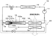
図1〜7により、本発明の一実施形態を説明する。本実施形態では、本発明に係るエジェクタ15を、図1に示すエジェクタ式冷凍サイクル10に適用している。このエジェクタ式冷凍サイクル10は、空調装置に適用されており室内へ送風される室内送風空気を冷却するものである。なお、図1は、本実施形態のエジェクタ式冷凍サイクル10の全体構成図である。
1-7 demonstrates one Embodiment of this invention. In this embodiment, the
エジェクタ式冷凍サイクル10は、流体である冷媒を圧縮して吐出する圧縮機11、圧縮機11から吐出された高圧冷媒を室外空気と熱交換させて放熱させる放熱器12、エジェクタ15から流出した冷媒を蒸発させて圧縮機11吸入側へ流出させる流出側蒸発器16、固定絞り17から流出した冷媒を蒸発させてエジェクタ15の冷媒吸引口152c側へ流出させる吸引側蒸発器18等を有して構成されている。
The ejector-
さらに、本実施形態のエジェクタ式冷凍サイクル10は、放熱器12から流出した冷媒を中間圧となるまで減圧させる膨張弁13、この膨張弁13にて減圧された冷媒の流れを分岐する分岐部14を有している。膨張弁13は、周知の温度式膨張弁で構成されており、流出側蒸発器16出口側冷媒の過熱度が予め定めた範囲となるように下流側に流出させる冷媒流量を調整するものである。
Furthermore, the ejector
分岐部14は、3つの流入出口を有する三方継手構造のもので、流入出口のうち1つを冷媒流入口とし、2つを冷媒流出口としたものである。そして、分岐部14の一方の冷媒流出口には、後述するエジェクタ15のノズル151の冷媒入口側が接続され、分岐部14の他方の冷媒流出口には、固定絞り17の冷媒入口側が接続されている。なお、この固定絞り17としてはオリフィスあるいはキャピラリチューブを採用できる。
The
また、エジェクタ15の冷媒出口側(具体的には、後述するボデー152の冷媒出口側)には、流出側蒸発器16の冷媒入口側が接続され、流出側蒸発器16の冷媒出口側には、圧縮機11の冷媒吸入口側が接続されている。固定絞り17の冷媒出口側には、吸引側蒸発器18の冷媒入口側が接続され、吸引側蒸発器18の冷媒出口側には、エジェクタ15のボデー152に形成された冷媒吸引口152cが接続されている。
The refrigerant outlet side of the ejector 15 (specifically, the refrigerant outlet side of the
さらに、本実施形態では、上述したエジェクタ式冷凍サイクル10を構成するサイクル構成機器のうち、図1において破線で囲まれたサイクル構成機器(具体的には、分岐部14、エジェクタ15、流出側蒸発器16、固定絞り17、吸引側蒸発器18)が、蒸発器ユニット20として一体的に構成されている。
Further, in the present embodiment, among the cycle constituent devices constituting the
より具体的には、本実施形態では、流出側蒸発器16および吸引側蒸発器18として、それぞれ冷媒を流通させる複数本のチューブと、この複数のチューブの両端側に配置されてチューブを流通する冷媒の集合あるいは分配を行う一対の集合分配用タンクとを有する、いわゆるタンクアンドチューブ型の熱交換器を採用している。
More specifically, in this embodiment, as the
そして、双方の蒸発器16、18の集合分配用タンクを同一部材にて形成することによって、双方の蒸発器16、18を一体化している。この際、流出側蒸発器16が吸引側蒸発器18に対して送風空気流れ風上側に配置されるように、双方の蒸発器16、18を送風空気流れに対して直列に配置している。
And the
また、エジェクタ15は、双方の蒸発器16、18のいずれかの集合分配用タンク内あるいは集合分配用タンクの長手方向と平行に延びる別タンク内に収容された状態で、集合分配用タンクあるいは別タンクの内壁面にろう付けにより接合されて一体化されている。分岐部14および固定絞り17についても、双方の蒸発器16、18にろう付け等の接合手段あるいはボルト締め等の機械的係合手段によって一体化されている。
The
次に、図2〜4を用いて、エジェクタ15の詳細構成について説明する。本実施形態のエジェクタ15は、エジェクタ式冷凍サイクル10において、分岐部14にて分岐された一方の中間圧冷媒を低圧冷媒となるまで減圧させる冷媒減圧手段としての機能を果たすとともに、高速で噴出する冷媒流の吸引作用によって冷媒を吸引(輸送)して循環させる冷媒輸送手段(冷媒循環手段)としての機能を果たす。
Next, the detailed configuration of the
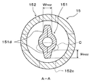
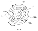
なお、図2は、エジェクタ15の軸方向断面図であり、図3は、図2の拡大A−A断面図であり、図4は、図2の拡大B−B断面図である。
2 is an axial sectional view of the
図2に示すように、エジェクタ15は、ノズル151およびボデー152を有して構成されている。ノズル151は、金属(本実施形態では、ステンレス合金)で形成された円筒状の母材をプレス加工することによって形成されたもので、略円筒状で冷媒の流れ方向に向かって先細り形状の先端部を有している。そして、内部に形成される冷媒通路面積を変化させ、冷媒を等エントロピ的に減圧させるように形成されている。
As shown in FIG. 2, the
具体的には、ノズル151の内部に形成される冷媒通路には、冷媒通路面積が最も縮小した喉部151aが形成され、さらに、喉部151aから冷媒流れ下流側に向かって冷媒通路面積が徐々に拡大する末広部151bが形成されている。つまり、ノズル151は、ラバールノズルとして構成されており、喉部151aにおける冷媒の流速が音速以上となるようにしている。もちろん、ノズル151を先細ノズルで構成してもよい。
Specifically, in the refrigerant passage formed inside the
また、ノズル151の先細り形状の先端部には、図2に示すように、冷媒を噴射する冷媒噴射口151cが形成されている。さらに、ノズル151には、図2、3に示すように、その軸線方向に延びるとともに外周側に突出する複数(本実施形態では2つ)のノズル側リブ151dが、ノズル151の軸線の周方向に等間隔(本実施形態では180°間隔)に形成されている。
Further, as shown in FIG. 2, a
このノズル側リブ151dは、上述したプレス加工時に、母材のうちノズル151に対して余肉となる一部の部位を、母材の外周側から山折り状に挟み込むように荷重をかけることによって形成されるものである。ここで、図3は、ノズル151の軸線方向に垂直な断面のうち、ノズル側リブ151dが形成されている部位における断面を示しており、特許請求の範囲に記載されたノズル151側の「基準断面」を示す図面である。
The nozzle-
さらに、図3に示す基準断面において、ノズル側リブ151dの形状は、外周側に向かって徐々に幅寸法Wnozが縮小する台形状に形成されている。この幅寸法Wnozは、ノズル側リブ151dの根本部同士を結ぶ直線に平行なノズル側リブ151dの厚み寸法として定義することができる。
Furthermore, in the reference cross section shown in FIG. 3, the shape of the nozzle-
また、図2、3に示すように、ノズル側リブ151dの最外周部(径方向先端部)は、ノズル151の最外周部よりも内周側に位置付けられている。換言すると、ノズル側リブ151dの外周側へ向かう高さ寸法Hnozは、ノズル151の最外周部を軸線方向に延長させた際に形成される円柱状空間内に収まる範囲の寸法となっている。
As shown in FIGS. 2 and 3, the outermost peripheral portion (radial tip portion) of the nozzle-
さらに、図2に示すように、ノズル151の冷媒噴射口151c側に形成されたノズル側リブ151dの高さ寸法Hnozは、冷媒流れ方向へ向かって徐々に小さくなっている。また、図3から明らかなように、ノズル151側の基準断面において、ノズル151は、複数の部材がつなぎ合わされることなく、環状に連続した単一の部材によって形成されている。
Furthermore, as shown in FIG. 2, the height dimension Hnoz of the nozzle-
ボデー152は、ノズル151と同様に金属(本実施形態では、アルミニウム)で形成された母材をプレス加工することによって略円筒状に形成されており、その内部にノズル151が収容される収容空間152a、および、後述する昇圧部(ディフューザ部)を構成する昇圧空間152bが形成されている。
The
より具体的には、収容空間152aの冷媒流れ下流側は、冷媒流れ方向に向かってノズル151の軸線方向に垂直な断面積が徐々に縮小する形状に形成されており、一方、昇圧空間152bは、冷媒流れ方向に向かってノズル151の軸線方向に垂直な断面積が徐々に拡大する形状に形成されている。
More specifically, the downstream side of the refrigerant flow in the
さらに、ボデー152の収容空間152a側には、ボデー152の内外を貫通する複数(本実施形態では4つ)の冷媒吸引口152cがノズル151の軸線の周方向に等間隔(本実施形態では90°間隔)に形成されている。冷媒吸引口152cは、吸引側蒸発器18から流出した冷媒を収容空間152a内へ導く貫通穴であり、ノズル151の外周側に配置されて、ノズル151の冷媒噴射口151cと連通するように設けられている。
Further, on the
従って、収容空間152aのうち、冷媒吸引口152c周辺には、冷媒を流入させる入口空間が形成され、ノズル151の先細り形状の先端部周辺の外周側とボデー152の内周側の間の空間には、収容空間152a内へ流入した吸引冷媒を昇圧空間152b側へ導く吸引通路152dが形成されている。
Therefore, an inlet space for allowing the refrigerant to flow is formed around the
昇圧空間152bは、図2に示すように、ノズル151および冷媒吸引口152cの冷媒流れ下流側に配置されて、ノズル151から噴射された噴射冷媒と冷媒吸引口152cから吸引された吸引冷媒とを混合させながら混合された冷媒の運動エネルギを圧力エネルギに変換するディフューザ部として機能する。
As shown in FIG. 2, the
さらに、収容空間152aの冷媒流れ下流側と昇圧空間152bの冷媒流れ上流側との
接続部には、流体通路面積が一定となったストレート部152fが形成されている。また
図2に示すように、ノズル151の軸線を含む断面における昇圧空間152bの形状(ボ
デー152の内周面が描く形状)は曲線状に変化している。
Furthermore, a
より具体的には、昇圧空間152bの入口側における冷媒通路面積の広がり度合が、出口側における冷媒通路面積の広がり度合よりも小さく変化している。換言すると、昇圧空間152bのノズル151の軸線を含む断面における形状は、内周側に向かって凸となる曲線で形成されている。
More specifically, the degree of expansion of the refrigerant passage area on the inlet side of the
さらに、ボデー152には、図2、4に示すように、その軸線方向に延びるとともに外周側に突出する複数(本実施形態では4つ)のボデー側リブ152eが軸線の周方向に等間隔(本実施形態では90°間隔)に形成されている。このボデー側リブ152eも、ノズル側リブ151dと同様に、プレス加工時に、母材のうちボデー152に対して余肉となる一部の部位を、母材の外周側から山折り状に挟み込むように荷重をかけることによって形成されるものである。
Further, as shown in FIGS. 2 and 4, the
ここで、図4は、ボデー152の軸線方向に垂直な断面のうち、ボデー側リブ152eが形成されている部位における断面を示しており、特許請求の範囲に記載されボデー152側の「基準断面」に対応する断面である。本実施形態では、図2の軸方向断面においてボデー側リブ152eと冷媒吸引口152cは重合しない範囲に形成されている。また、「基準断面」は、冷媒吸引口152cを含まない断面であるものとする。
Here, FIG. 4 shows a cross section at a portion where the
さらに、図4に示す基準断面において、ボデー側リブ152eの形状は、ノズル側リブ151dの形状と同様に、外周側に向かって徐々に幅寸法Wbdが縮小する台形状に形成されている。また、ボデー側リブ152eの高さ寸法Hbdは、ボデー側リブ152eの最外周部(径方向先端部)がボデー152の最外周部と一致する寸法となっている。
Further, in the reference cross section shown in FIG. 4, the shape of the
また、図4から明らかなように、ボデー152側の基準断面において、ボデー152は、複数の部材がつなぎ合わされることなく、環状に連続した単一の部材によって形成されている。
As is clear from FIG. 4, in the reference cross section on the
次に、上記構成のエジェクタ式冷凍サイクル10の作動を説明する。圧縮機11が作動すると、圧縮機11が冷媒を吸入して、圧縮して吐出する。圧縮機11から吐出された高温高圧冷媒は、放熱器12にて放熱する。放熱器12にて放熱した高圧冷媒は、膨張弁13にて減圧膨張される。
Next, the operation of the
この際、膨張弁13では、流出側蒸発器16出口冷媒(圧縮機吸入冷媒)の過熱度が所定値となるように弁開度(冷媒流量)が調整される。膨張弁13にて減圧膨張された中間圧冷媒の流れは、分岐部14にて、エジェクタ15のノズル151側へ流れる冷媒流れと、固定絞り17側へ流れる冷媒流れとに分流される。
At this time, in the
エジェクタ15のノズル151側へ流入した冷媒は、ノズル151にて、等エントロピ的に減圧膨張されて、冷媒噴射口151cから冷媒が高速度の冷媒流となって噴射される。そして、この噴射冷媒の吸引作用により、吸引側蒸発器18から流出した冷媒が、冷媒吸引口152cから吸引される。
The refrigerant that has flowed into the
ノズル151から噴射された噴射冷媒と冷媒吸引口152cより吸引された吸引冷媒は、ディフューザ部を構成する昇圧空間152bへ流入する。昇圧空間152bでは噴射冷媒と吸引冷媒が混合されるとともに、冷媒通路面積の拡大により、冷媒の速度エネルギが圧力エネルギに変換されるため、冷媒の圧力が上昇する。エジェクタ15(具体的には昇圧部)から流出した冷媒は、流出側蒸発器16へ流入する。
The injection refrigerant injected from the
流出側蒸発器16では、流入した低圧冷媒が室内送風空気から吸熱して蒸発する。これにより、室内送風空気が冷却される。そして、流出側蒸発器16から流出した気相冷媒は、圧縮機11に吸入されて、再び圧縮される。
In the
一方、分岐部14から固定絞り17側へ流出した冷媒は、固定絞り17で等エンタルピ的に減圧膨張されて、吸引側蒸発器18へ流入する。吸引側蒸発器18へ流入した冷媒は、流出側蒸発器16通過後の室内送風空気から吸熱して蒸発する。これにより、室内送風空気がさらに冷却されて室内へ送風される。吸引側蒸発器18から流出した冷媒は、冷媒吸引口152cからエジェクタ15内へ吸引される。
On the other hand, the refrigerant that has flowed out from the
以上の如く、本実施形態のエジェクタ式冷凍サイクル10では、室内送風空気を流出側蒸発器16→流出側蒸発器18の順に通過させて同一の冷却対象空間を冷却できる。この際、ディフューザ部(昇圧空間152b)の昇圧作用によって流出側蒸発器16の冷媒蒸発温度を流出側蒸発器18の冷媒蒸発温度よりも上昇させることができるので、流出側蒸発器16および流出側蒸発器18の冷媒蒸発温度と送風空気との温度差を確保して、効率的に送風空気を冷却できる。
As described above, in the ejector-
また、流出側蒸発器16下流側を圧縮機11吸入側に接続しているので、昇圧部(昇圧空間152b)で昇圧された冷媒を圧縮機11に吸入させることができる。その結果、圧縮機11の吸入圧を上昇させて、圧縮機11の駆動動力を低減させることができるので、サイクルの成績係数(COP)を向上させることができる。
In addition, since the downstream side of the
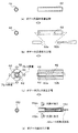
次に、図5、6を用いて、本実施形態のエジェクタ15の製造方法について説明する。なお、図5は、ノズル151の製造工程を説明する説明図であり、図6は、ボデー152の製造工程を説明する説明図である。
Next, the manufacturing method of the
まず、ノズル151を製造する際には、ノズル151をプレス成形で製造するための筒状のノズル用の母材41を用意する(図5(a):ノズル用母材準備工程)。本実施形態では、具体的に、平板状のステンレス合金に対して深絞り加工を施して有底円筒状としたものを、ノズル用の母材41としている。
First, when manufacturing the
次に、ノズル用母材準備工程にて用意されたノズル用の母材41の内部空間に、その外形がノズル151の冷媒通路と略相似形状に形成されたノズル用芯金51を挿入する(図5(b):ノズルの芯金挿入工程)。前述の如く、本実施形態のノズル151は、ラバールノズルとして形成されるので、ノズル用の母材41の底面に予め貫通穴を設けておき、ノズル用の母材41の両端部から分割されたノズル用芯金51a、51bを挿入する。
Next, a
これにより、プレス加工工程の後に、ノズル用の母材41の両端部から容易にノズル用芯金51a、51bを取り外すことができる。なお、ノズル151を先細ノズルとして形成する場合は、ノズル用の母材41の開放端側から単一のノズル用芯金51を挿入してもよい。また、ノズル用芯金51は、ノズル151の冷媒通路の形状を所望の寸法諸元とするために、硬度の高い超鋼材料等で形成されていることが望ましい。
Thus, it can be removed after enough pressing engineering, readily
次に、ノズルの芯金挿入工程後のノズル用芯金51が挿入された状態のノズル用の母材41に対して、ノズル151の軸線に直交する径方向からプレス加工を施す(図5(c):ノズルのプレス加工工程)。この際、本実施形態では、プレス型61をノズル側リブ151dと同数(本実施形態では2つ)に分割しておき、隣接するプレス型61の間にノズル側リブ151dが形成されるようにしている。
Next, the
そして、ノズルのプレス加工工程によって形成されたノズル151からノズル用芯金を取り外して、ノズル151が製造される。なお、ノズル151を先細ノズルとして形成する場合は、ノズルのプレス加工工程後に、底面に貫通穴を設けてもよいし、ラバールノズルとして形成する場合と同様に、ノズルの芯金挿入工程時に底面に貫通穴を設けておいてもよい。
Then, the
また、ボデー152を製造する際には、図6に示すように、基本的にノズル151と同様に製造する。まず、ボデー152をプレス成形で製造するための筒状のボデー用の母材42を用意する(図6(a):ボデー用母材準備工程)。本実施形態では、アルミニウムの管材を、ボデー用の母材42としている。
Further, when the
次に、ボデー用母材準備工程にて用意されたボデー用の母材42の内部空間に、一端側から、外形が収容空間152aの相似形状に形成されたボデー用芯金52aを挿入し、他端側から外形が昇圧空間152bの相似形状に形成されたボデー用芯金52bを挿入する(図6(b):ボデーの芯金挿入工程)。
Next, a
次に、ボデーの芯金挿入工程後のボデー用芯金52a、52bが挿入された状態のボデー用の母材42に対して、ノズル151の軸線に直交する径方向からプレス加工を施す(図6(c):ボデーのプレス加工工程)。この際、本実施形態では、プレス型62をボデー側リブ152eと同数(本実施形態では4つ)に分割しておき、隣接するプレス型62の間にボデー側リブ152eが形成されるようにしている。
Next, the
次に、ボデーのプレス加工工程によって形成されたボデー152からボデー用芯金52
a、52bを取り外し、ボデー152の円筒状面に冷媒吸引口152cを形成するととも
に、ボデー152の内部の収容空間152aと昇圧空間152bとの接続部にストレート
部152fを形成する(ボデーの追加工工程)。
Next, the cored bar 52 for the body is formed from the
a, remove the 52 b, add together to form a
より具体的には、冷媒吸引口152cは、穴開け加工によって形成されており、ボデー
152の軸線方向から見たときに、ボデー側リブ152eと重合しない位置に形成されて
いる。さらに、収容空間152aと昇圧空間152bとの接続部に形成されるストレート
部152fは、ボデー152の内部に円筒状の刃具をノズル151の軸線に沿って移動さ
せることによって形成されている。
More specifically, the
次に、上記の如く形成されたノズル151を、ボデー152の収容空間152a内へ収容して仮固定する(ノズルとボデーとの仮固定工程)。この際、前述の図4に示すように、ノズル151の軸線方向から見たときに、ノズル側リブ151dが、軸線の中心と冷媒吸引口152cの中心を結ぶ線と重合するように配置する。
Next, the
ここで、本実施形態では、ノズル151の冷媒流れ入口側の最外周部の径寸法が、ボデー152の収容空間152aの内径寸法よりも僅かに大きく形成されたシマリ嵌めの関係となっている。これにより、ノズル151を収容空間152a内へ収容することにより、ノズル151とボデー152が仮固定される。
Here, in this embodiment, the diameter dimension of the outermost peripheral part on the refrigerant flow inlet side of the
さらに、前述の如く、本実施形態のエジェクタ15は、流出側蒸発器16または吸引側蒸発器18の集合分配用タンク内あるいは別タンク内に収容されるので、ノズルとボデーとの仮固定行程後の仮固定状態のエジェクタ15を、さらに、集合分配用タンク内あるいは別タンク内へ収容して仮固定する(エジェクタの仮固定工程)。
Further, as described above, the
この仮固定についても、エジェクタ15(具体的には、ボデー152)の外径寸法を、集合分配用タンク内あるいは別タンクの内径寸法よりも僅かに大きく形成してシマリ嵌めの関係とすることによってなされている。 For this temporary fixing, the outer diameter of the ejector 15 (specifically, the body 152) is formed to be slightly larger than the inner diameter of the collecting / distributing tank or another tank so as to be fitted with a simple fit. Has been made.
そして、エジェクタ15、チューブおよび集合分配用タンク内あるいは別タンク等が仮固定された流出側蒸発器16および吸引側蒸発器18を、加熱手段である加熱炉内に投入する。
Then, the
これにより、ノズル151の外表面、ボデー152の内周面および外周面、さらに、集合分配用タンク内あるいは別タンクの内周面に予めクラッドされたろう材を溶融させる。そして、再びろう材が凝固するまで冷却することで、エジェクタ15が製造されると同時に、蒸発器ユニット20が製造される(エジェクタ接合工程)。
As a result, the brazing material clad in advance on the outer surface of the
さらに、本実施形態では、上記の如く製造されたエジェクタ15を採用しているので、以下のような優れた効果を得ることができる。
Furthermore, in this embodiment, since the
本実施形態では、ノズル151およびボデー152を、塑性加工の一種であるプレス加工により形成しているので、ノズル151およびボデー152を切削加工等により形成する場合に対して、製造コストの低減と加工時間の短縮を両立させることができる。つまり、本実施形態のエジェクタ15は、大量生産に適したものとなる。
In this embodiment, since the
なお、上述したボデーの追加工工程では、プレス加工とは異なる加工方法によって冷媒
吸引口152cの形成およびストレート部152fの形成を行っているが、これらの加工
はノズル151あるいはボデー152の全体を切削加工にて形成する場合に対して簡単な
加工であり、本実施形態のエジェクタ15の大量生産性に悪影響を及ぼすものではない。
In the additional processing step of the body as described above, it is performed to form the forming and
さらに、ノズル151およびボデー152には、それぞれノズル側リブ151dおよびボデー側リブ152eが形成されているので、プレス加工される母材41、42のうち、ノズル151あるいはボデー152に対して余肉となる部分をノズル側リブ151dおよびボデー側リブ152eとすることができる。
Further, since the
これにより、プレス加工時によってノズル151およびボデー152の一部が局部的に極端に引き延ばされて肉厚が薄くなってしまう部位が形成されること抑制できる。従って、製造可能なエジェクタ15の形状の範囲を広げることができ、本実施形態のエジェクタ15は、幅広い用途に適用可能な種々の寸法諸元に形成することができる。
Thereby, it is possible to suppress the formation of a portion where the
さらに、プレス加工により形成されるノズル側リブ151dおよびボデー側リブ152eが、それぞれノズル151の軸線方向に延びるとともに外周側に突出しているので、余肉となる部分がノズル151およびボデー152の内周側に突出して、ノズル151およびボデー152の内周側に形成される冷媒通路面積が所望の寸法諸元からずれてしまうことを回避できる。
Furthermore, since the nozzle-
さらに、ノズル側リブ151dおよびボデー側リブ152eが、それぞれノズル151およびボデー152の補強部材として機能して、ノズル151およびボデー152の変形を抑制することもできる。
Furthermore, the nozzle-
さらに、基準断面において、ノズル151およびボデー152が、複数の部材がつなぎ合わされることなく、環状に連続した単一の部材によって形成されているので、ノズル151およびボデー152から内部を通過する流体が漏れてしまうことを防止するための接合処理を行う必要がない。従って、より一層、エジェクタの製造原価を低減できる。
Further, in the reference cross section, the
ところで、本実施形態のように、プレス加工時に母材41、42の外周側から山折り状に挟み込むように荷重をかけることによって、ノズル側リブ151dおよびボデー側リブ152eを形成すると、図7に示すように、ノズル151あるいはボデー152の内周面のうちリブ151d、152eの合わせ面に対応する部位に凹み部が形成されやすい。なお、図7は、図3のC部の拡大図であって、ノズル側リブ151dを例として凹み部を説明するための図である。
By the way, when the nozzle-
これに対して、本実施形態のエジェクタ15によれば、基準断面におけるノズル側リブ151dおよびボデー側リブ152eの形状が、外周側に向かって徐々に幅寸法Wnoz、Wbdが縮小する形状に形成されているので、プレス加工時に凹み部を潰す方向の荷重をかけやすくなる。その結果、凹み部を小さくすることができ、エジェクタの形状を所望の寸法諸元に近づけやすくなる。
On the other hand, according to the
また、本実施形態のように、ノズルの芯金挿入工程およびボデーの心金挿入工程にて、それぞれ分割された二つのノズル用芯金51a、51bおよびボデー用芯金52a、52bを挿入する場合、2つの芯金同士の合わせ面に、母材41、42が流れ込んでバリを生じさせやすい。
Further, as in the present embodiment, in the case of inserting two divided
特に、ステンレス合金に対して柔らかいアルミニウム製の母材42をプレス加工して形
成されるボデー152では、大きなバリが生じてボデー152内部を流通する冷媒のエネ
ルギ損失を生じさせるおそれがある。これに対して、本実施形態のエジェクタ15では、
ボデーの追加工工程時に収容空間152aと昇圧空間152bとの接続部にストレート部
152fを形成しているので、確実にバリを除去できる。
In particular, in the
Since the
さらに、本実施形態のボデーの追加工工程では、ボデー152の軸線方向から見たときに、冷媒吸引口152cをボデー側リブ152eと重合しない位置に形成しているので、追加工工程時に、ボデー側リブ152eの影響を受けることなく容易に冷媒吸引口152c形成することができる。
Furthermore, in the body additional process in the present embodiment, the
また、本実施形態のノズルとボデーとの仮固定工程では、ノズル151の軸線方向から見たときに、ノズル側リブ151dが、軸線の中心と冷媒吸引口152cの中心を結ぶ線と重合するように配置しているので、ノズル側リブ151dを冷媒吸引口152cから吸引される吸引冷媒の流入方向に沿って配置することができる。従って、ノズル側リブ151dによって吸引冷媒に生じる圧力損失を低減できる。
In the temporary fixing step between the nozzle and the body of the present embodiment, the nozzle-
さらに、本実施形態のノズル側リブ151dの最外周部(先端部)は、ノズル151の最外周部よりも内周側に位置付けられているので、ノズルとボデーとの仮固定工程時に、ノズル側リブ151dがボデー152の内周面に当接することなく、ノズル151をボデー152の内部に容易に収容できる。
Furthermore, since the outermost peripheral portion (tip portion) of the nozzle-
さらに、ノズル151の冷媒噴射口151c側に形成されたノズル側リブ151dの高さ寸法Hnozが冷媒流れ下流側に向かって徐々に小さくなっているので、吸引通路152dを流れる冷媒に生じる圧力損失を低減できる。
Further, since the height dimension Hnoz of the nozzle-
(他の実施形態)
本発明は上述の実施形態に限定されることなく、本発明の趣旨を逸脱しない範囲内で、以下のように種々変形可能である。
(Other embodiments)
The present invention is not limited to the above-described embodiment, and can be variously modified as follows without departing from the spirit of the present invention.
(1)上述の実施形態では、ノズル151およびボデー152の双方をプレス加工にて形成した例を説明しているが、ノズル151およびボデー152の少なくとも一方をプレス加工で形成すれば、幅広い用途に適用可能で、かつ、製造コストの低減と加工時間の短縮の両立させた大量生産に適するエジェクタを提供することができる。
(1) In the above-described embodiment, an example in which both the
(2)上述の実施形態では、エジェクタ15を空調装置用のエジェクタ式冷凍サイクル10に適用した例を説明したが、本発明のエジェクタの適用対象はこれに限定されない。例えば、冷蔵・冷凍装置あるいは冷温保存庫用のエジェクタ式冷凍サイクル(ヒートポンプサイクル)に適用してもよいし、流体吸引口(本実施形態では冷媒吸引口152c)に生じる負圧を利用して真空を発生させる真空ポンプ等に適用してもよい。
(2) In the above-described embodiment, the example in which the
さらに、本実施形態では、エジェクタ式冷凍サイクル10の冷媒については言及していないが、冷媒として通常のフロン系冷媒、炭化水素系冷媒、二酸化炭素等を採用してもよい。また、エジェクタ式冷凍サイクル10が、圧縮機11吐出冷媒圧力が冷媒の臨界圧力を超える超臨界冷凍サイクルを構成していてもよい。
Furthermore, although the refrigerant of the
さらに、本実施形態では、エジェクタ15を蒸発器ユニット20として、分岐部14、流出側蒸発器16、固定絞り17、吸引側蒸発器18等と一体化させた例を説明したが、この際、ボデー側リブ152eの最外周部(先端部)を、集合分配用タンク内あるいは別タンクにエジェクタ15にろう付けする際のろう付け面としてもよい。もちろん、エジェクタ15を蒸発器ユニット20として一体化させなくてもよい。
Furthermore, in the present embodiment, an example in which the
(3)上述の実施形態では、ノズル用の母材41として、板状の金属部材に対して深絞り加工を施して筒状に形成したものを採用した例を説明したが、ノズル用の母材41として金属製(例えば、ステンレス合金製)の管材を採用してもよい。また、上述の実施形態では、ボデー用の母材42として、管材を採用した例を説明したが、ボデー用の母材42として板状の金属部材に対して深絞り加工を施して筒状に形成したものを採用してもよい。
(3) In the above-described embodiment, as an example of the
(4)上述の実施形態では、ノズル151の製造工程とボデー152の製造工程とを行う順序について言及していないが、ノズル151およびボデー152は独立に製造可能なものであるから、ノズル151およびボデー152の製造順序は、いずれかを先に製造してもよし、同時に製造してもよい。
(4) In the above-described embodiment, the order of performing the manufacturing process of the
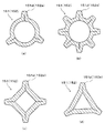
(5)上述の実施形態では、ノズル側リブ151dが2つ形成された略円筒状のノズル151およびボデー側リブ152eが4つ形成された略円筒状のボデー152を採用した例を説明したが、ノズル151およびボデー152は、これに限定されない。
(5) In the above-described embodiment, an example in which the substantially
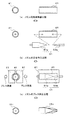
例えば、図8(a)(b)に示すように、ノズル側リブ151dおよびボデー側リブ152eの数を変更してもよい。この場合は、プレス型61、62についてもノズル側リブ151dおよびボデー側リブ152eと同数に分割することが望ましい。また、図8(c)(d)に示すように、ノズル151およびボデー152は筒状であれば断面円形状に限定されず、多角形状に形成してもよい。
For example, as shown in FIGS. 8A and 8B, the number of nozzle-
なお、図8は、ノズル151およびボデー152の断面を示す図面であって、上述の実施形態の図2、3に対応する図面である。
FIG. 8 is a drawing showing a cross section of the
15 エジェクタ
151 ノズル
151d ノズル側リブ
152 ボデー
152a 収容空間
152b 昇圧部(昇圧空間)
152c 流体吸引口
152f ストレート部
152e ボデー側リブ
41、42 母材
DESCRIPTION OF
152c
Claims (10)
前記ノズル(151)から噴射される高速度の噴射流体によって流体が吸引される流体吸引口(152c)および前記ノズル(151)から噴射された噴射流体と前記流体吸引口(152c)から吸引された吸引流体とを混合させて昇圧させる昇圧部(152b)が形成されたボデー(152)とを備えるエジェクタであって、
前記ノズル(151)および前記ボデー(152)のうち少なくとも一方は、金属母材(41、42)をプレス加工することにより形成されており、
前記ノズル(151)あるいは前記ボデー(152)には、前記ノズル(151)の軸線方向に延びるとともに外周側に突出するリブ(151d、152e)が形成されており、
さらに、前記ノズル(151)あるいは前記ボデー(152)の前記軸線方向に垂直な断面のうち、前記リブ(151d、152e)が形成されている部位における断面を基準断面としたときに、
前記リブ(151d、152e)は前記ノズル(151)あるいは前記ボデー(152)を形成するための前記プレス加工の余肉となる部分にて形成され、これにより、前記基準断面における前記リブ(151d、152e)を含む前記ノズル(151)あるいは前記ボデー(152)は、複数の部材がつなぎ合わされることなく、連続した単一の部材によって形成されていることを特徴とするエジェクタ。 A nozzle (151) for jetting the fluid under reduced pressure;
The fluid suction port (152c) from which fluid is sucked by the high-speed jet fluid jetted from the nozzle (151) and the jetted fluid jetted from the nozzle (151) and the fluid suction port (152c) An ejector comprising a body (152) formed with a boosting unit (152b) for mixing and suctioning a suction fluid;
Wherein at least one of the nozzles (151) and said body (152) is formed by a metal base material (41, 42) for pressing,
The nozzle (151) or the body (152) is formed with ribs (151d, 152e) extending in the axial direction of the nozzle (151) and projecting to the outer peripheral side,
Further, of the cross section perpendicular to the axial direction before Symbol nozzle (151) or said body (152), the rib (151d, 152e) cross section is taken as a reference cross section at a site is formed,
The ribs (151d, 152e) are formed in a portion that becomes a surplus of the press working for forming the nozzle (151) or the body (152), whereby the rib (151d, 152e) in the reference cross section is formed. The ejector characterized in that the nozzle (151) or the body (152) including 152e) is formed by a single continuous member without a plurality of members being joined together.
前記ボデー(152)の内部には、前記ノズル(151)が収容される収容空間(152a)および前記昇圧部を形成する昇圧空間(152b)が形成されており、
前記収容空間(152a)の流体流れ下流側(152d)は、流体流れ方向に向かって前記軸線方向に垂直な断面績が徐々に縮小する形状に形成され、
前記昇圧空間(152b)は、流体流れ方向に向かって前記軸線方向に垂直な断面績が徐々に拡大する形状に形成され、
前記収容空間(152a)の前記流体流れ下流側(152d)と前記昇圧空間(152b)の流体流れ上流側との接続部には、流体通路面積が一定となったストレート部(152f)が形成されていることを特徴とする請求項1または2に記載のエジェクタ。 The body (152) is formed by the press work,
Inside the body (152), an accommodation space (152a) in which the nozzle (151) is accommodated and a boosting space (152b) that forms the boosting part are formed,
The fluid flow downstream side (152d) of the accommodation space (152a) is formed in a shape in which the cross-sectional profile perpendicular to the axial direction gradually decreases toward the fluid flow direction,
The pressurizing space (152b ) is formed in a shape in which the cross-sectional profile perpendicular to the axial direction gradually increases toward the fluid flow direction,
The connecting portion of the fluid flow upstream of the fluid flow downstream (152d) and the booster space (152 b) of the accommodating space (152a), the straight portion of the fluid passage area becomes constant (152 f) is formed The ejector according to claim 1, wherein the ejector is provided.
前記流体吸引口(152c)は、前記ボデー(152)を前記軸線方向から見たときに、前記ボデー(152)に形成された前記リブ(152e)と重合しない位置に配置されていることを特徴とする請求項1ないし4のいずれか1つに記載のエジェクタ。 The body (152) is formed by the press work,
The fluid suction port (152c) is disposed at a position where it does not overlap with the rib (152e) formed on the body (152) when the body (152) is viewed from the axial direction. The ejector according to any one of claims 1 to 4.
前記ノズル(151)に形成された前記リブ(151d)は、前記ボデー(152)を前記軸線方向から見たときに、前記軸線の中心と前記流体吸引口(152c)の中心を結ぶ線と重合する位置に配置されていることを特徴とする請求項1ないし5のいずれか1つに記載のエジェクタ。 The nozzle (151) is formed by the press work,
The rib (151d) formed on the nozzle (151) overlaps with a line connecting the center of the axis and the center of the fluid suction port (152c) when the body (152) is viewed from the axial direction. The ejector according to claim 1, wherein the ejector is disposed at a position where the ejector is located.
前記ノズル(151)に形成された前記リブ(151d、152e)の最外周部は、前記ノズル(151)の最外周部よりも内周側に位置付けられていることを特徴とする請求項1ないし6のいずれか1つに記載のエジェクタ。 The nozzle (151) is formed by the press work,
The outermost peripheral part of the rib (151d, 152e) formed in the nozzle (151) is positioned on the inner peripheral side of the outermost peripheral part of the nozzle (151). The ejector according to any one of 6.
前記ノズル(151)の流体噴射口(151c)側に形成された前記リブ(151d、152e)の外周側へ向かう高さ寸法(Hnoz)は、流体流れ方向へ向かって徐々に小さくなっていることを特徴とする請求項1ないし7のいずれか1つに記載のエジェクタ。 The nozzle (151) is formed by the press work,
The height dimension (Hnoz) toward the outer peripheral side of the ribs (151d, 152e) formed on the fluid ejection port (151c) side of the nozzle (151) is gradually decreased toward the fluid flow direction. The ejector according to claim 1, wherein:
前記ノズル(151)から噴射される高速度の噴射流体によって流体が吸引される流体吸引口(152c)および前記ノズル(151)から噴射された噴射流体と前記流体吸引口(152c)から吸引された吸引流体とを混合させて昇圧させる昇圧部(152b)が形成されたボデー(152)とを備えるエジェクタの製造方法であって、The fluid suction port (152c) from which fluid is sucked by the high-speed jet fluid jetted from the nozzle (151) and the jetted fluid jetted from the nozzle (151) and the fluid suction port (152c) A method of manufacturing an ejector comprising a body (152) formed with a pressure increasing part (152b) for increasing pressure by mixing with a suction fluid,
前記ノズル(151)および前記ボデー(152)のうち少なくとも一方の母材として金属母材(41、42)を用意する母材準備工程と、A base material preparation step of preparing a metal base material (41, 42) as at least one base material of the nozzle (151) and the body (152);
前記金属母材(41、42)をプレス加工することにより前記ノズル(151)および前記ボデー(152)のうち少なくとも一方を形成するとともに、前記ノズル(151)の軸線方向に延びるとともに外周側に突出するリブ(151d、152e)を前記ノズル(151)あるいは前記ボデー(152)に形成するプレス加工工程とを備え、At least one of the nozzle (151) and the body (152) is formed by pressing the metal base material (41, 42), and extends in the axial direction of the nozzle (151) and protrudes to the outer peripheral side. Forming a rib (151d, 152e) to be formed on the nozzle (151) or the body (152),
前記プレス加工工程では、前記プレス加工の余肉となる部分にて前記リブ(151d、152e)を形成し、これにより、前記ノズル(151)あるいは前記ボデー(152)の前記軸線方向に垂直な断面のうち、前記リブ(151d、152e)が形成されている部位における断面を基準断面としたときに、In the pressing process, the ribs (151d, 152e) are formed in the portion that becomes the surplus of the pressing process, and thereby the cross section perpendicular to the axial direction of the nozzle (151) or the body (152). Among them, when a cross section at a portion where the ribs (151d, 152e) are formed is a reference cross section,
前記基準断面における前記リブ(151d、152e)を含む前記ノズル(151)あるいは前記ボデー(152)を、複数の部材がつなぎ合わされることなく、連続した単一の部材によって形成することを特徴とするエジェクタの製造方法。The nozzle (151) or the body (152) including the rib (151d, 152e) in the reference cross section is formed by a single continuous member without a plurality of members being joined together. Manufacturing method of ejector.
Priority Applications (4)
| Application Number | Priority Date | Filing Date | Title |
|---|---|---|---|
| JP2010075119A JP5407983B2 (en) | 2010-03-29 | 2010-03-29 | Ejector |
| DE102011014352.1A DE102011014352B4 (en) | 2010-03-29 | 2011-03-18 | ejector |
| CN201110076980.XA CN102207107B (en) | 2010-03-29 | 2011-03-23 | Ejector |
| US13/065,695 US8814532B2 (en) | 2010-03-29 | 2011-03-28 | Ejector |
Applications Claiming Priority (1)
| Application Number | Priority Date | Filing Date | Title |
|---|---|---|---|
| JP2010075119A JP5407983B2 (en) | 2010-03-29 | 2010-03-29 | Ejector |
Publications (2)
| Publication Number | Publication Date |
|---|---|
| JP2011208523A JP2011208523A (en) | 2011-10-20 |
| JP5407983B2 true JP5407983B2 (en) | 2014-02-05 |
Family
ID=44656728
Family Applications (1)
| Application Number | Title | Priority Date | Filing Date |
|---|---|---|---|
| JP2010075119A Expired - Fee Related JP5407983B2 (en) | 2010-03-29 | 2010-03-29 | Ejector |
Country Status (4)
| Country | Link |
|---|---|
| US (1) | US8814532B2 (en) |
| JP (1) | JP5407983B2 (en) |
| CN (1) | CN102207107B (en) |
| DE (1) | DE102011014352B4 (en) |
Families Citing this family (11)
| Publication number | Priority date | Publication date | Assignee | Title |
|---|---|---|---|---|
| CN103161775B (en) * | 2011-12-13 | 2016-01-13 | 中国科学院大连化学物理研究所 | A kind of one-dimensional expansion large-mach-number nozzle vane and processing thereof and application |
| CN102678640A (en) * | 2012-06-04 | 2012-09-19 | 太仓奥科机械设备有限公司 | Vacuum generator |
| CN102829002B (en) * | 2012-08-27 | 2014-12-31 | 中国航天科技集团公司第四研究院四0一所 | Small-size annular nozzle ejector with exchangeable throat part |
| JP6056596B2 (en) * | 2013-03-27 | 2017-01-11 | 株式会社デンソー | Ejector |
| DE102013208274A1 (en) * | 2013-05-06 | 2014-11-20 | Wacker Chemie Ag | Fluidized bed reactor and process for producing granular polysilicon |
| CN103395627B (en) * | 2013-07-12 | 2016-06-22 | 裕东(中山)机械工程有限公司 | A kind of air conveying ejector of coaxial-type |
| JP6003844B2 (en) * | 2013-08-09 | 2016-10-05 | 株式会社デンソー | Ejector |
| US10857507B2 (en) * | 2016-03-23 | 2020-12-08 | Alfa Laval Corporate Ab | Apparatus for dispersing particles in a liquid |
| US20190209980A1 (en) * | 2016-10-03 | 2019-07-11 | Dlhbowles, Inc. | Gas to gas aspirator with improved entrainment efficiency |
| CN106762860B (en) * | 2016-12-21 | 2018-07-24 | 武汉大学 | A kind of fluid flow built-in stabilizers based on jet flow cavitation |
| JP6926988B2 (en) * | 2017-11-27 | 2021-08-25 | トヨタ自動車株式会社 | Fuel gas supply device |
Family Cites Families (23)
| Publication number | Priority date | Publication date | Assignee | Title |
|---|---|---|---|---|
| US265246A (en) * | 1882-10-03 | Ejector for raising liquids | ||
| US2040890A (en) * | 1932-06-03 | 1936-05-19 | Margaret M Wrentmore | Jet pump |
| US2100185A (en) * | 1936-11-06 | 1937-11-23 | Simon Marmorek | Apparatus for the movement of viscous materials |
| US2396290A (en) * | 1945-03-01 | 1946-03-12 | Schwarz Sigmund | Sludge pump |
| US3166020A (en) * | 1961-09-20 | 1965-01-19 | Hypro Engineering Inc | Venturi mixer nozzle |
| JPS58117400A (en) * | 1981-12-28 | 1983-07-12 | Toshiba Corp | Jet pump |
| US4595344A (en) * | 1982-09-30 | 1986-06-17 | Briley Patrick B | Ejector and method of controlling same |
| JPS6144000U (en) * | 1984-08-25 | 1986-03-22 | いすゞ自動車株式会社 | Ejector |
| JP2764217B2 (en) * | 1989-09-20 | 1998-06-11 | 株式会社荏原製作所 | Jet pump |
| DE4022811A1 (en) | 1990-07-18 | 1992-01-23 | Bayerische Motoren Werke Ag | LOCK WITH AUXILIARY MOTOR, IN PARTICULAR DOOR LOCK FOR A MOTOR VEHICLE |
| US5117648A (en) * | 1990-10-16 | 1992-06-02 | Northeastern University | Refrigeration system with ejector and working fluid storage |
| DE19747268A1 (en) * | 1997-10-25 | 1999-04-29 | Bosch Gmbh Robert | Dual fluid injection system for internal combustion engine |
| JP2003326196A (en) * | 2002-05-13 | 2003-11-18 | Denso Corp | Ejector |
| US6877960B1 (en) * | 2002-06-05 | 2005-04-12 | Flodesign, Inc. | Lobed convergent/divergent supersonic nozzle ejector system |
| JP4140386B2 (en) * | 2003-01-15 | 2008-08-27 | 株式会社デンソー | Ejector device and fuel cell system using the same |
| DE102004007319A1 (en) * | 2004-02-14 | 2005-08-25 | Robert Bosch Gmbh | Fuel supply system for vehicles comprises pump incorporating fuel line and mixing pipe which are connected by sloping bar on one lip of fuel line |
| JP2006132897A (en) | 2004-11-09 | 2006-05-25 | Taiheiyo Seiko Kk | Enlarged-reduced diameter pipe and ejector using the same |
| JP2007051833A (en) * | 2005-08-18 | 2007-03-01 | Denso Corp | Ejector refrigeration cycle |
| JP2007253175A (en) | 2006-03-22 | 2007-10-04 | Denso Corp | Ejector outer cylinder molding method |
| JP2008151017A (en) * | 2006-12-15 | 2008-07-03 | Denso Corp | Ejector device and manufacturing method thereof |
| SG157325A1 (en) * | 2008-05-29 | 2009-12-29 | Denso Corp | Ejector and manufacturing method thereof |
| JP4811493B2 (en) * | 2008-05-29 | 2011-11-09 | 株式会社デンソー | Ejector and manufacturing method of ejector |
| DE102008059898A1 (en) * | 2008-12-02 | 2010-06-10 | Behr Gmbh & Co. Kg | Ejector for a refrigeration circuit and manufacturing process |
-
2010
- 2010-03-29 JP JP2010075119A patent/JP5407983B2/en not_active Expired - Fee Related
-
2011
- 2011-03-18 DE DE102011014352.1A patent/DE102011014352B4/en active Active
- 2011-03-23 CN CN201110076980.XA patent/CN102207107B/en active Active
- 2011-03-28 US US13/065,695 patent/US8814532B2/en active Active
Also Published As
| Publication number | Publication date |
|---|---|
| US8814532B2 (en) | 2014-08-26 |
| DE102011014352A1 (en) | 2012-04-26 |
| JP2011208523A (en) | 2011-10-20 |
| CN102207107A (en) | 2011-10-05 |
| DE102011014352B4 (en) | 2017-02-02 |
| US20110236227A1 (en) | 2011-09-29 |
| CN102207107B (en) | 2014-03-12 |
Similar Documents
| Publication | Publication Date | Title |
|---|---|---|
| JP5407983B2 (en) | Ejector | |
| JP5370028B2 (en) | Ejector | |
| US6779360B2 (en) | Ejector having throttle variable nozzle and ejector cycle using the same | |
| AU2002301307B2 (en) | Ejector cycle system | |
| US9372014B2 (en) | Ejector-type refrigeration cycle device | |
| JP6048339B2 (en) | Ejector | |
| JP5786765B2 (en) | Ejector | |
| JP3903766B2 (en) | Ejector | |
| US7165948B2 (en) | Ejector | |
| JP5585559B2 (en) | Ejector | |
| JP5338481B2 (en) | Ejector | |
| JP2004239145A (en) | Ejector | |
| JP2004116807A (en) | Ejector type decompression device | |
| JP5429233B2 (en) | Ejector | |
| JP2008111376A (en) | Ejector | |
| JP2010064146A (en) | Method for manufacturing container for absorbing fluid shock or mechanical shock | |
| US20060236521A1 (en) | Pipe fixing structure and pipe fixing method | |
| JP5104583B2 (en) | Ejector | |
| US20120234027A1 (en) | Supersonic Cooling Nozzle with Airfoils |
Legal Events
| Date | Code | Title | Description |
|---|---|---|---|
| A621 | Written request for application examination |
Free format text: JAPANESE INTERMEDIATE CODE: A621 Effective date: 20120516 |
|
| A131 | Notification of reasons for refusal |
Free format text: JAPANESE INTERMEDIATE CODE: A131 Effective date: 20130319 |
|
| A977 | Report on retrieval |
Free format text: JAPANESE INTERMEDIATE CODE: A971007 Effective date: 20130322 |
|
| A521 | Request for written amendment filed |
Free format text: JAPANESE INTERMEDIATE CODE: A523 Effective date: 20130514 |
|
| TRDD | Decision of grant or rejection written | ||
| A01 | Written decision to grant a patent or to grant a registration (utility model) |
Free format text: JAPANESE INTERMEDIATE CODE: A01 Effective date: 20131008 |
|
| A61 | First payment of annual fees (during grant procedure) |
Free format text: JAPANESE INTERMEDIATE CODE: A61 Effective date: 20131021 |
|
| R151 | Written notification of patent or utility model registration |
Ref document number: 5407983 Country of ref document: JP Free format text: JAPANESE INTERMEDIATE CODE: R151 |
|
| R250 | Receipt of annual fees |
Free format text: JAPANESE INTERMEDIATE CODE: R250 |
|
| R250 | Receipt of annual fees |
Free format text: JAPANESE INTERMEDIATE CODE: R250 |
|
| R250 | Receipt of annual fees |
Free format text: JAPANESE INTERMEDIATE CODE: R250 |
|
| R250 | Receipt of annual fees |
Free format text: JAPANESE INTERMEDIATE CODE: R250 |
|
| R250 | Receipt of annual fees |
Free format text: JAPANESE INTERMEDIATE CODE: R250 |
|
| LAPS | Cancellation because of no payment of annual fees |