JP5407947B2 - Damper device and fluid transmission device - Google Patents
Damper device and fluid transmission device Download PDFInfo
- Publication number
- JP5407947B2 JP5407947B2 JP2010052662A JP2010052662A JP5407947B2 JP 5407947 B2 JP5407947 B2 JP 5407947B2 JP 2010052662 A JP2010052662 A JP 2010052662A JP 2010052662 A JP2010052662 A JP 2010052662A JP 5407947 B2 JP5407947 B2 JP 5407947B2
- Authority
- JP
- Japan
- Prior art keywords
- plate
- drive
- driven
- cylindrical portion
- clutch
- Prior art date
- Legal status (The legal status is an assumption and is not a legal conclusion. Google has not performed a legal analysis and makes no representation as to the accuracy of the status listed.)
- Expired - Fee Related
Links
Images

Classifications
-
- F—MECHANICAL ENGINEERING; LIGHTING; HEATING; WEAPONS; BLASTING
- F16—ENGINEERING ELEMENTS AND UNITS; GENERAL MEASURES FOR PRODUCING AND MAINTAINING EFFECTIVE FUNCTIONING OF MACHINES OR INSTALLATIONS; THERMAL INSULATION IN GENERAL
- F16H—GEARING
- F16H45/00—Combinations of fluid gearings for conveying rotary motion with couplings or clutches
- F16H45/02—Combinations of fluid gearings for conveying rotary motion with couplings or clutches with mechanical clutches for bridging a fluid gearing of the hydrokinetic type
- F16H2045/021—Combinations of fluid gearings for conveying rotary motion with couplings or clutches with mechanical clutches for bridging a fluid gearing of the hydrokinetic type three chamber system, i.e. comprising a separated, closed chamber specially adapted for actuating a lock-up clutch
-
- F—MECHANICAL ENGINEERING; LIGHTING; HEATING; WEAPONS; BLASTING
- F16—ENGINEERING ELEMENTS AND UNITS; GENERAL MEASURES FOR PRODUCING AND MAINTAINING EFFECTIVE FUNCTIONING OF MACHINES OR INSTALLATIONS; THERMAL INSULATION IN GENERAL
- F16H—GEARING
- F16H45/00—Combinations of fluid gearings for conveying rotary motion with couplings or clutches
- F16H45/02—Combinations of fluid gearings for conveying rotary motion with couplings or clutches with mechanical clutches for bridging a fluid gearing of the hydrokinetic type
- F16H2045/0221—Combinations of fluid gearings for conveying rotary motion with couplings or clutches with mechanical clutches for bridging a fluid gearing of the hydrokinetic type with damping means
- F16H2045/0226—Combinations of fluid gearings for conveying rotary motion with couplings or clutches with mechanical clutches for bridging a fluid gearing of the hydrokinetic type with damping means comprising two or more vibration dampers
- F16H2045/0231—Combinations of fluid gearings for conveying rotary motion with couplings or clutches with mechanical clutches for bridging a fluid gearing of the hydrokinetic type with damping means comprising two or more vibration dampers arranged in series
-
- F—MECHANICAL ENGINEERING; LIGHTING; HEATING; WEAPONS; BLASTING
- F16—ENGINEERING ELEMENTS AND UNITS; GENERAL MEASURES FOR PRODUCING AND MAINTAINING EFFECTIVE FUNCTIONING OF MACHINES OR INSTALLATIONS; THERMAL INSULATION IN GENERAL
- F16H—GEARING
- F16H45/00—Combinations of fluid gearings for conveying rotary motion with couplings or clutches
- F16H45/02—Combinations of fluid gearings for conveying rotary motion with couplings or clutches with mechanical clutches for bridging a fluid gearing of the hydrokinetic type
- F16H2045/0273—Combinations of fluid gearings for conveying rotary motion with couplings or clutches with mechanical clutches for bridging a fluid gearing of the hydrokinetic type characterised by the type of the friction surface of the lock-up clutch
- F16H2045/0284—Multiple disk type lock-up clutch
Landscapes
- Mechanical Operated Clutches (AREA)
Description
本発明は、入力部材と回転方向に一体化され得るドライブ要素と、入力部材に付与されたトルクの伝達対象である出力部材に固定されるドリブン要素とを含み、入力部材と出力部材との間でトルクの変動を吸収するダンパ装置およびそれを備えた流体伝動装置に関する。 The present invention includes a drive element that can be integrated with an input member in a rotation direction, and a driven element that is fixed to an output member that is a transmission target of torque applied to the input member, between the input member and the output member. The present invention relates to a damper device that absorbs torque fluctuations and a fluid transmission device including the damper device.
従来、車両に搭載される流体伝動装置として、クラッチ機構と、第1ダンパ機構と第2ダンパ機構とからなるダンパ機構とを含むロックアップ装置を備えたトルクコンバータが知られている(例えば、特許文献1参照)。このトルクコンバータでは、第1ダンパ機構が1対のリティーニングプレートと、センタープレートと、複数の第1コイルスプリングとを有しており、センタープレートは、1対のリティーニングプレートの軸方向間に相対回転可能に配置される。また、第2ダンパ機構は、ドリブンプレートと、複数の第2コイルスプリングとを有しており、第2コイルスプリングの端部同士の間には、第1センタープレートの一部が軸方向から挿入される。これにより、第1および第2ダンパ機構が別々のアッセンブリとして取り扱われることになることから、ロックアップ装置の組付および分解が容易となる。また、ダンパ機構における第2コイルスプリングの配置の自由度が高まることから、トルクコンバータの流体室内のスペースを有効に利用可能となる。 Conventionally, a torque converter including a lockup device including a clutch mechanism and a damper mechanism including a first damper mechanism and a second damper mechanism is known as a fluid transmission device mounted on a vehicle (for example, a patent) Reference 1). In this torque converter, the first damper mechanism has a pair of retaining plates, a center plate, and a plurality of first coil springs, and the center plate is between the pair of retaining plates in the axial direction. Arranged so that relative rotation is possible. The second damper mechanism has a driven plate and a plurality of second coil springs, and a part of the first center plate is inserted from the axial direction between the ends of the second coil springs. Is done. As a result, the first and second damper mechanisms are handled as separate assemblies, so that the lockup device can be easily assembled and disassembled. Moreover, since the freedom degree of arrangement | positioning of the 2nd coil spring in a damper mechanism increases, the space in the fluid chamber of a torque converter can be utilized effectively.
上記従来のダンパ機構では、第1ダンパ機構(第1コイルスプリング)と第2ダンパ機構(第2コイルスプリング)とを軸方向にオフセットすることで第2コイルスプリングの配置の自由度を高めている。しかしながら、上記ダンパ機構では、流体室内の外周側に配置される第2コイルスプリングがドリブンプレートにより保持されることから、流体室内(タービンランナの背後)にドリブンプレートの配置スペースを確保する必要がある。従って、配置箇所のスペースの有効利用という観点からみれば、上記ダンパ機構には、なお改善の余地がある。 In the conventional damper mechanism, the first coil mechanism (first coil spring) and the second damper mechanism (second coil spring) are offset in the axial direction to increase the degree of freedom in arranging the second coil spring. . However, in the damper mechanism, since the second coil spring disposed on the outer peripheral side in the fluid chamber is held by the driven plate, it is necessary to secure a space for arranging the driven plate in the fluid chamber (behind the turbine runner). . Therefore, the damper mechanism still has room for improvement from the viewpoint of effective use of the space at the arrangement location.
そこで、本発明によるダンパ装置およびそれを備えた流体伝動装置は、ダンパ装置の配置箇所のスペースを有効に利用できるようにすることを主目的とする。 Therefore, the damper device and the fluid transmission device including the damper device according to the present invention are mainly intended to make it possible to effectively use the space at the location of the damper device.
本発明によるダンパ装置および流体伝動装置は、上述の主目的を達成するために以下の手段を採っている。 The damper device and the fluid transmission device according to the present invention employ the following means in order to achieve the main object described above.
本発明によるダンパ装置は、
駆動源からのトルクが伝達されるドライブ要素と、第1弾性部材を介して前記ドライブ要素と係合する中間要素と、前記第1弾性部材に対して軸方向にオフセットされた第2弾性部材を介して前記中間部材と係合するドリブン要素とを有するダンパ装置において、
前記中間要素は、前記第1弾性部材との当接部と前記第2弾性部材との当接部との間に軸方向に延びる円筒部を有し、前記ドライブ要素および前記ドリブン要素の一方は、前記中間要素の前記円筒部の内周を回転自在に支持する支持部を有し、前記ドライブ要素および前記ドリブン要素の他方は、前記中間要素の前記円筒部の外周により回転自在に支持される被支持部を有することを特徴とする。
The damper device according to the present invention comprises:
A drive element to which torque from a drive source is transmitted; an intermediate element engaged with the drive element via a first elastic member; and a second elastic member offset in the axial direction with respect to the first elastic member. A damper device having a driven element engaged with the intermediate member via,
The intermediate element has a cylindrical portion extending in an axial direction between a contact portion with the first elastic member and a contact portion with the second elastic member, and one of the drive element and the driven element is A support portion that rotatably supports an inner periphery of the cylindrical portion of the intermediate element, and the other of the drive element and the driven element is rotatably supported by an outer periphery of the cylindrical portion of the intermediate element. It has a supported part, It is characterized by the above-mentioned.
このダンパ装置を構成する中間要素は、第1弾性部材との当接部と第2弾性部材との当接部との間に軸方向に延びる円筒部を有し、ドライブ要素およびドリブン要素の一方は、中間要素の円筒部の内周を回転自在に支持する支持部を有し、ドライブ要素およびドリブン要素の他方は、中間要素の円筒部の外周により回転自在に支持される被支持部を有する。すなわち、中間要素の円筒部は、当該円筒部の内側に配置されるドライブ要素およびドリブン要素の一方の支持部により回転自在に支持され、中間要素の円筒部の外側に配置されるドライブ要素およびドリブン要素の他方の被支持部は、円筒部を介して当該円筒部の内側に配置されるドライブ要素およびドリブン要素の一方の支持部により回転自在に支持される。これにより、ドライブ要素およびドリブン要素の一方が中間要素の円筒部の内側に配置されると共に、ドライブ要素およびドリブン要素の他方が一方に対して軸方向にオフセットされた状態で中間要素の円筒部の外側に配置されることになる。従って、円筒部の内側に配置されるドライブ要素およびドリブン要素の一方の外側や、円筒部の外側に配置されるドライブ要素およびドリブン要素の他方の内側にスペースを確保することができる。また、支持部、円筒部および被支持部を径方向からみて軸方向にオーバラップさせることで、ダンパ装置の軸方向長さの増加を抑制することができる。更に、ドライブ要素およびドリブン要素の一方の支持部によって中間要素とドライブ要素およびドリブン要素の他方とを軸周りに支持することが可能となるので、ドライブ要素およびドリブン要素の他方を回転自在に支持するために専用部材を用いたり、当該ドライブ要素およびドリブン要素の他方の一部分をダンパ装置の軸心に向けて延長したりする必要がなくなり、そのような部材の配置スペースを削減することができる。この結果、ダンパ装置の配置箇所のスペースを有効に利用することが可能となる。 The intermediate element constituting the damper device has a cylindrical portion extending in the axial direction between the contact portion with the first elastic member and the contact portion with the second elastic member, and one of the drive element and the driven element. Has a support portion that rotatably supports the inner periphery of the cylindrical portion of the intermediate element, and the other of the drive element and the driven element has a supported portion that is rotatably supported by the outer periphery of the cylindrical portion of the intermediate element. . That is, the cylindrical portion of the intermediate element is rotatably supported by one support portion of the drive element and the driven element disposed inside the cylindrical portion, and the drive element and the driven portion disposed outside the cylindrical portion of the intermediate element. The other supported part of the element is rotatably supported by one support part of the drive element and the driven element arranged inside the cylindrical part via the cylindrical part. Accordingly, one of the drive element and the driven element is arranged inside the cylindrical portion of the intermediate element, and the other of the drive element and the driven element is axially offset with respect to the one of the cylindrical portion of the intermediate element. It will be arranged outside. Therefore, it is possible to secure a space on the outside of one of the drive element and the driven element arranged inside the cylindrical portion, or on the inside of the other of the drive element and the driven element arranged outside the cylindrical portion. Moreover, the increase of the axial direction length of a damper apparatus can be suppressed by making a support part, a cylindrical part, and a to-be-supported part overlap in an axial direction seeing from radial direction. Further, since the support portion of one of the drive element and the driven element can support the intermediate element and the other of the drive element and the driven element around the axis, the other of the drive element and the driven element is rotatably supported. Therefore, it is not necessary to use a dedicated member or to extend the other part of the drive element and the driven element toward the axis of the damper device, and the arrangement space for such a member can be reduced. As a result, it is possible to effectively use the space where the damper device is disposed.
また、前記中間要素の前記円筒部と前記支持部と前記被支持部とは、径方向からみて軸方向にオーバラップしてもよい。このように、支持部と被支持部とのうちの外側に位置する一方が内側に位置する他方を囲むようにすることで、ダンパ装置の軸方向長さの増加を抑制することができる。 Further, the cylindrical portion, the support portion, and the supported portion of the intermediate element may overlap in the axial direction when viewed from the radial direction. In this way, an increase in the axial length of the damper device can be suppressed by surrounding one of the support part and the supported part located outside on the other side.
更に、前記ドライブ要素は、前記駆動源と接続される入力部材と回転方向に一体化され得る第1ドライブプレートと、前記中間要素の前記円筒部の外周により回転自在に支持される前記被支持部を有すると共に前記第1ドライブプレートに固定される第2ドライブプレートとを含むものであってもよく、前記ドリブン要素は、前記中間要素の前記円筒部の内周を回転自在に支持する前記支持部を有すると共に前記出力部材に固定される第1ドリブンプレートと、前記駆動源からのトルクの伝達対象である出力部材と前記第1ドリブンプレートとの少なくとも何れか一方に固定される第2ドリブンプレートとを含むものであってもよく、前記第1弾性部材は、前記第1ドライブプレートと前記第2ドライブプレートとにより保持されてもよく、前記第2弾性部材は、前記第1ドリブンプレートと前記第2ドリブンプレートとにより保持されてもよく、前記中間要素は環状に形成されており、該中間要素の前記円筒部よりも外周側の部分は、前記第1弾性部材と係合する第1係合部を有すると共に前記第1ドライブプレートと前記第2ドライブプレートとの間に移動可能に配置されてもよく、該中間要素の前記円筒部よりも内周側の部分は、前記第2弾性部材と係合する第2係合部を有すると共に前記第1ドリブンプレートと前記第2ドリブンプレートとの間に移動可能に配置されてもよい。これにより、ドライブ要素がドリブン要素に対して軸方向にオフセットされた状態で中間要素の円筒部の外側に配置されることになるので、ドライブ要素の内側かつドリブン要素の軸方向における側方にスペースを確保することが可能となる。また、第1弾性部材が第1および第2ドライブプレートにより保持されると共に、第2弾性部材が第1および第2ドリブンプレートにより保持されるようにすれば、中間要素の荷重負担を軽減することが可能となる。 Furthermore, the drive element is supported by a first drive plate that can be integrated in a rotational direction with an input member connected to the drive source, and the supported part that is rotatably supported by the outer periphery of the cylindrical part of the intermediate element. And a second drive plate fixed to the first drive plate, wherein the driven element rotatably supports the inner periphery of the cylindrical part of the intermediate element A first driven plate that is fixed to the output member, and a second driven plate that is fixed to at least one of the output member that is a transmission target of torque from the drive source and the first driven plate, The first elastic member may be held by the first drive plate and the second drive plate, The second elastic member may be held by the first driven plate and the second driven plate, the intermediate element is formed in an annular shape, and a portion of the intermediate element on the outer peripheral side than the cylindrical portion May have a first engagement portion that engages with the first elastic member and may be movably disposed between the first drive plate and the second drive plate, and the cylindrical portion of the intermediate element The inner peripheral portion may have a second engagement portion that engages with the second elastic member, and may be movably disposed between the first driven plate and the second driven plate. As a result, the drive element is disposed outside the cylindrical portion of the intermediate element in an axially offset state with respect to the driven element, so that there is a space inside the drive element and laterally in the driven element in the axial direction. Can be secured. Further, if the first elastic member is held by the first and second drive plates and the second elastic member is held by the first and second driven plates, the load on the intermediate element can be reduced. Is possible.
本発明による流体伝動装置は、上記ダンパ装置を備えた流体伝動装置であって、前記ドライブ要素の内側で前記ドリブン要素と前記軸方向に隣り合うように配置されており、該ドライブ要素と前記入力部材とを連結すると共に両者の連結を解除することができるクラッチを含むことを特徴とする。この流体伝動装置のダンパ装置は、当該ダンパ装置の配置箇所のスペースを有効に利用できるようにするものである。従って、この流体伝動装置では、ダンパ装置を介して入力部材と出力部材とを連結するためのクラッチの配置スペースを確保しつつ装置全体を容易にコンパクト化することができる。また、ドライブ要素の内側でドリブン要素と軸方向に隣り合うようにクラッチを配置することで、ダンパ装置の配置箇所のスペースをより有効に利用可能となる。 A fluid transmission device according to the present invention is a fluid transmission device including the above-described damper device, and is disposed inside the drive element so as to be adjacent to the driven element in the axial direction. The drive element and the input It includes a clutch capable of connecting the members and releasing the connection between them. The damper device of this fluid transmission device makes it possible to effectively use the space at the location where the damper device is arranged. Therefore, in this fluid transmission device, the entire device can be easily made compact while securing the arrangement space of the clutch for connecting the input member and the output member via the damper device. In addition, by arranging the clutch so as to be adjacent to the driven element in the axial direction inside the drive element, the space at the arrangement position of the damper device can be used more effectively.
また、前記クラッチは、前記入力部材により前記軸方向に摺動自在に支持されるピストンと、前記ピストンと対向するようにスプラインを介して前記入力部材により支持されるクラッチハブと、前記ピストンと前記クラッチハブとの間に配置されるリターンスプリングと、前記ピストンと前記クラッチハブとの間に位置するように前記ドライブ要素により前記軸方向に摺動自在に支持される第1クラッチプレートと、前記ピストンと前記クラッチハブとの間で前記第1クラッチプレートと隣り合うように前記クラッチハブにより前記軸方向に摺動自在に支持される第2クラッチプレートとを含むものであってもよく、前記入力部材には、前記クラッチハブに対して前記ピストンとは反対側で該クラッチハブと当接するようにスナップリングが取り付けられてもよく、前記クラッチハブの前記ピストン側の面と前記入力部材との間には弾性体が配置されてもよい。これにより、クラッチハブと入力部材との間に回転方向における隙間(ガタ)が存在していても、弾性部材によりクラッチハブと入力部材との相対移動を規制することができるので、入力部材に動力が付与されたときにクラッチハブの入力部材に対する相対移動(ガタつき)によりノイズが発生するのを抑制することができる。また、クラッチハブの入力部材に対する相対移動を規制するためにリターンスプリングのバネ定数を大きくする必要がなくなるので、クラッチの係合に必要な流体圧が高まるのを抑制することができる。 The clutch includes a piston slidably supported in the axial direction by the input member, a clutch hub supported by the input member via a spline so as to face the piston, the piston, A return spring disposed between the clutch hub, a first clutch plate that is slidably supported in the axial direction by the drive element so as to be positioned between the piston and the clutch hub, and the piston And a second clutch plate that is slidably supported in the axial direction by the clutch hub so as to be adjacent to the first clutch plate between the clutch and the clutch hub, and the input member Includes a snap ring so as to contact the clutch hub on the opposite side of the piston from the piston. Ri attached is at best, may be placed an elastic body between said input member and said piston-side surface of said clutch hub. As a result, even if there is a gap (backlash) in the rotational direction between the clutch hub and the input member, the relative movement between the clutch hub and the input member can be restricted by the elastic member. It is possible to suppress the generation of noise due to relative movement (backlash) of the clutch hub with respect to the input member. Further, since it is not necessary to increase the spring constant of the return spring in order to restrict the relative movement of the clutch hub with respect to the input member, it is possible to suppress an increase in the fluid pressure necessary for engaging the clutch.
この場合、前記弾性体は、前記リターンスプリングの内側に配置されてもよい。これにより、流体伝動装置をよりコンパクト化することができる。 In this case, the elastic body may be disposed inside the return spring. Thereby, the fluid transmission device can be made more compact.
そして、前記流体伝動装置は、複数のポンプブレードを有すると共に前記入力部材に固定されるポンプインペラと、複数のタービンブレードを有すると共に前記出力部材に固定されるタービンランナとを含む流体継手を備えてもよく、前記ドライブ要素が前記タービンブレードと前記軸方向に隣り合うように配置され、前記ドリブン要素が前記タービンブレードの内側に配置されてもよい。 The fluid transmission device includes a fluid coupling including a plurality of pump blades and a pump impeller fixed to the input member, and a turbine runner including a plurality of turbine blades and fixed to the output member. Alternatively, the drive element may be disposed adjacent to the turbine blade in the axial direction, and the driven element may be disposed inside the turbine blade.
次に、本発明を実施するための形態を実施例を用いて説明する。 Next, the form for implementing this invention is demonstrated using an Example.
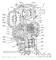
図1は、本発明の実施例に係る流体伝動装置1を示す断面図であり、図2は、流体伝動装置1の要部を示す断面図である。同図に示す流体伝動装置1は、動力発生源としてのエンジンを備えた車両に発進装置として搭載されるものであり、図示しないエンジンのクランクシャフトに接続される入力側センターピース(入力部材)2と、入力側センターピース2に固定されるフロントカバー3と、フロントカバー3に固定されたポンプインペラ(入力側流体伝動要素)4と、ポンプインペラ4と共に流体継手を構成するタービンランナ(出力側流体伝動要素)5と、タービンランナ5が固定されるタービンハブ(出力部材)6と、タービンハブ6に固定されるダンパユニット7と、入力側センターピース2とダンパユニット7とを連結すると共に両者の連結を解除することができる多板摩擦式のロックアップクラッチ8とを含む。
FIG. 1 is a cross-sectional view showing a fluid transmission device 1 according to an embodiment of the present invention, and FIG. 2 is a cross-sectional view showing a main part of the fluid transmission device 1. A fluid transmission device 1 shown in the figure is mounted as a starting device on a vehicle equipped with an engine as a power generation source, and an input side center piece (input member) 2 connected to a crankshaft of an engine (not shown). A front cover 3 fixed to the input side center piece 2, a pump impeller (input side fluid transmission element) 4 fixed to the front cover 3, and a turbine runner (output side fluid) constituting a fluid coupling with the pump impeller 4 The transmission element 5, the turbine hub (output member) 6 to which the turbine runner 5 is fixed, the
入力側センターピース2は、図示されないエンジンのクランクシャフトに連結され、タービンハブ6は、図示されない自動変速機(AT)あるいは無段変速機(CVT)の入力軸(図示省略)に連結(スプライン嵌合)される。ポンプインペラ4は、フロントカバー3に密に固定されるポンプシェル40と、ポンプシェル40の内面に配設された複数のポンプブレード41とを有する。タービンランナ5は、タービンハブ6に固定されるタービンシェル50と、タービンシェル50の内面に配設された複数のタービンブレード51とを有する。実施例において、タービンシェル50は、タービンブレード51の取付部よりも内側に位置するように形成された環状の凹部52を背面側(エンジン側すなわち図中右側)に有する。
The input side center piece 2 is connected to a crankshaft of an engine (not shown), and the
ダンパユニット7は、フロントカバー3やポンプインペラ4のポンプシェル40により画成される油室内の外周側領域に配置されると共にロックアップクラッチ8により入力側センターピース2と回転方向に一体化され得るドライブ要素70と、当該油室内の内周側領域においてタービンランナ5のタービンシェル50に形成された凹部52内に少なくともその一部分が配置されると共にタービンハブ6に固定されるドリブン要素72と、複数の外周側コイルスプリング(第1弾性部材)73を介してドライブ要素70と係合すると共に複数の内周側コイルスプリング(第2弾性部材)74を介してドリブン要素72と係合する環状の中間プレート(中間要素)75とを含む。
The
ドライブ要素70は、図2に示すように、フロントカバー3側(エンジン側)に配置される環状の第1ドライブプレート701と、ポンプシェル40側(変速機側)に配置される環状の第2ドライブプレート702とを含む。第1ドライブプレート701は、それぞれ周方向に延在して外周側コイルスプリング73を収容する複数のスプリング収容部701aを外周側に有すると共に、それぞれ軸方向に延びる複数のスプライン701sを内周側に有する。また、各スプリング収容部701aの一端には、対応する外周側コイルスプリング73の一端と当接する当接部701bが形成されている。第2ドライブプレート702は、第1ドライブプレート701の各スプリング収容部701aに収容された外周側コイルスプリング73を支持するスプリング支持部702aを外周側に有すると共に、軸方向に延びる短尺の円筒部(被支持部)702cを内周側に有する。そして、第1ドライブプレート701と第2ドライブプレート702との間には、中間プレート75の外周側の部分が軸周りに回転可能に配置され、第1ドライブプレート701と第2ドライブプレート702とは、複数のリベット(図1参照)を介して互いに連結(固定)される。
As shown in FIG. 2, the
ドリブン要素72は、図2に示すように、フロントカバー3側(エンジン側)に配置される環状の第1ドリブンプレート721と、ポンプシェル40側(変速機側)に配置される環状の第2ドリブンプレート722とを含む。第1ドリブンプレート721は、軸方向に延びると共に上記第2ドライブプレート702の円筒部702cと概ね同一の軸方向長さを有する短尺の円筒部721c(支持部)を外周側に有すると共に、それぞれ周方向に延在して内周側コイルスプリング74を支持する複数のスプリング支持部721aを有する。第2ドリブンプレート722は、それぞれ第1ドリブンプレート721の対応するスプリング支持部721aと対向する複数のスプリング支持部722aを有する。各内周側コイルスプリング74は、第1ドリブンプレート721のスプリング支持部721aとそれに対応する第2ドリブンプレート722のスプリング支持部722aとにより保持され、各内周側コイルスプリング74の一端は、第1および第2ドリブンプレート721および722の少なくとも何れか一方に形成された当接部(図示せず)と当接する。そして、第1ドリブンプレート721と第2ドリブンプレート722との間には、中間プレート75の内周側の部分が軸周りに回転可能に配置され、第1および第2ドリブンプレート721および722の内周側端部は、リベットを介してタービンハブ6に固定される。
As shown in FIG. 2, the driven
中間プレート75は、図2に示すように、第1および第2ドライブプレート701および702により保持された対応する外周側コイルスプリング73の他端とそれぞれ当接する複数の外周側係合部(第1係合部)75oを外周側に有すると共に、第1および第2ドリブンプレート721および722により保持された対応する内周側コイルスプリング74の他端とそれぞれ当接する複数の内周側係合部75i(第2係合部)を内周側に有する。また、中間プレート75は、外周側の部分すなわち外周側係合部(第1係合部)75oと内周側の部分すなわち内周側係合部75i(第2係合部)との間に軸方向に延びる円筒部75cを有する。中間プレート75の外周側の部分が第1ドライブプレート701と第2ドライブプレート702との間に配置された際、中間プレート75の円筒部75cの外周面は、第2ドライブプレート702の円筒部702cの内周面と摺接し、中間プレート75の内周側の部分が第1ドリブンプレート721と第2ドリブンプレート722との間に配置された際、中間プレート75の円筒部75cの内周面は、第1ドリブンプレート721の円筒部721cの外周面と摺接する。すなわち、中間プレート75の円筒部75cは、当該円筒部75cの内側に配置されるドリブン要素72の第1ドリブンプレート721の円筒部(支持部)721cにより回転自在に支持され、中間プレート75の円筒部75cの外側に配置されるドライブ要素70の第2ドライブプレート702の円筒部(被支持部)702cは、円筒部75cを介して当該円筒部75cの内側に配置される第1ドリブンプレート721の円筒部721cにより回転自在に支持される。
As shown in FIG. 2, the
これにより、第1および第2ドリブンプレート721および722すなわちダンパユニット7がタービンハブ6に固定された際には、ドリブン要素72が中間プレート75の円筒部75cの内側かつタービンシェル50の凹部52内に配置されると共に、ドライブ要素70がドリブン要素72に対して軸方向かつフロントカバー3側(エンジン側)にオフセットされた状態で中間プレート75の円筒部75cの外側かつタービンブレード51の側方に配置される。従って、中間プレート75の円筒部75cの内側に配置されるドリブン要素72の外側にタービンブレード51やそれらを支持するタービンシェル50の一部の配置スペースが確保されると共に、中間プレート75の円筒部75cの外側に配置されるドライブ要素70の内側にもスペースが確保される。また、ドリブン要素72の支持部としての円筒部721cと、中間プレートの円筒部75cと、ドライブ要素70の被支持部としての円筒部702cとは、径方向からみて軸方向にオーバラップし、ドリブン要素72の支持部としての円筒部721cにより中間プレート75およびドライブ要素70が軸周りに回転自在に支持されることになる。
Thus, when the first and second driven
更に、実施例において、第1ドリブンプレート721の円筒部721c、中間プレート75の円筒部75c、および第2ドライブプレート702の円筒部702cは、円筒部721cと円筒部75cとの摺接面と円筒部75cと円筒部702cとの摺接面とが概ね同一の面積を有すると共に径方向からみて軸方向にほぼ完全に重なり合うように形成される。すなわち、第1ドリブンプレート721の円筒部721cと第2ドライブプレート702の円筒部702cとのうちの外側に位置する円筒部702cは、内側に位置する円筒部721cを包囲する。これにより、中間プレート75ひいてはダンパユニット7の全体の軸方向長さの増加を抑制すると共に、中間プレート75に対して加えられる曲げモーメントを小さくして当該中間プレート75の耐久性を向上させることが可能となる。更に、上記実施例のように、外周側コイルスプリング73が第1および第2ドライブプレート701および702により保持されると共に、内周側コイルスプリング74が第1および第2ドリブンプレート721および722により保持されるようにすれば、中間プレート75の荷重負担を軽減することができるので、中間プレート75の厚みを必要以上に増やす必要がなくなる。加えて、円筒部75cを有する中間プレート75は、プレス加工(曲げ加工)等により容易に形成可能であり、このようにして中間プレート75を形成して中間部に曲げ部分を設ければ、中間プレート75の強度を向上させることができる。
Further, in the embodiment, the
ロックアップクラッチ8は、図1および図2に示すように、中間プレート75の円筒部75cの外側に配置されるドライブ要素70の内側に画成されるスペースにドリブン要素72と軸方向に隣り合うように配置される。ロックアップクラッチ8は、入力側センターピース2により軸方向に摺動自在に支持されるロックアップピストン80と、ロックアップピストン80と対向するように入力側センターピース2により支持されるクラッチハブ81と、ロックアップピストン80とクラッチハブ81との間に配置されるリターンスプリング82と、ロックアップピストン80とクラッチハブ81との間に位置するようにドライブ要素70の第1ドライブプレート701により複数のスプライン701sを介して軸方向に摺動自在に支持される複数の第1クラッチプレート83と、ロックアップピストン80とクラッチハブ81との間で第1クラッチプレート83と隣り合うようにクラッチハブ81により複数のスプラインを介して軸方向に摺動自在に支持される複数の第2クラッチプレート84とを含む。
As shown in FIGS. 1 and 2, the
ロックアップピストン80は、入力側センターピース2の径方向に延びる部分やフロントカバー3に近接して配置され、ロックアップピストン80の背面と入力側センターピース2とフロントカバー3との間には、入力側センターピース2に形成された作動油供給孔2aや図示しない変速機の入力軸に形成された油路を介して図示しない油圧制御ユニットに接続されるロックアップ室85が画成される。また、クラッチハブ81は、入力側センターピース2の軸方向に延びる部分に形成された複数のスプライン2sに嵌合されると共に、タービンランナ5側(ロックアップピストン80とは反対側)で入力側センターピース2に取り付けられたスナップリング86と当接する。そして、クラッチハブ81のピストン側の面と入力側センターピース2との間には弾性体としての皿バネ87がリターンスプリングの内側に位置するように配置され、クラッチハブ81は、スナップリング86と皿バネ87とにより入力側センターピース2に対して軸方向に位置決めされる。
The lock-up
これにより、図示しない油圧制御ユニットから作動油供給孔2a等を介してロックアップ室85内に作動油(ロックアップ圧)を供給すれば、ロックアップピストン80がクラッチハブ81に向けて移動し、ロックアップピストン80とクラッチハブ81とにより第1および第2クラッチプレート83,84が挟み付けられることで入力側センターピース2がダンパユニット7を介してタービンハブ6にロック(直結)され、それによりエンジンからの動力がタービンハブ6を介して変速機の入力軸に機械的かつ直接的に伝達されるようになる。なお、ロックアップ室85の作動油の導入を停止すれば、ロックアップ室85内の作動油は入力側センターピース2に形成された作動油排出孔2bから入力軸の油路へと流出し、それによりロックアップが解除されることになる。
As a result, if hydraulic oil (lockup pressure) is supplied into the
また、実施例のロックアップクラッチ8のように、スナップリング86と皿バネ87とによりクラッチハブ81を入力側センターピース2に対して軸方向に位置決めすることで、クラッチハブ81と入力側センターピース2との間(スプライン嵌合部)に回転方向における隙間(ガタ)が存在していても、弾性部材としての皿バネ87によりクラッチハブ81と入力側センターピース2との相対移動を規制することができるので、エンジンから入力側センターピース2に動力が付与されたときにクラッチハブ81の入力側センターピース2に対する相対移動(ガタつき)によりノイズが発生するのを抑制することができる。また、クラッチハブ81の入力側センターピース2に対する相対移動を規制するためにリターンスプリング82のバネ定数を大きくする必要がなくなるので、ロックアップクラッチ8の係合に必要なロックアップ圧が高まるのを抑制することができる。
Further, like the
次に上述のように構成される発進装置としての流体伝動装置1の動作について説明する。流体伝動装置1を搭載した車両では、発進前にロックアップクラッチ8の係合が解除され、エンジンが始動されてアイドル状態にあるときには、流体伝動装置1は、フロントカバー3を介して入力側センターピース2に接続されたポンプインペラ4がエンジンと同一回転数で回転すると共にタービンランナ5が回転することなく停止するストール状態にある。ストール状態からエンジンの回転数および出力トルクが高まると、エンジンからの動力が入力側センターピース2、フロントカバー3を介してポンプインペラ4へと伝達され、ポンプインペラ4の回転に応じた作動油の流れによりタービンランナ5が回転する。これにより、エンジンからの動力が流体継手としてのポンプインペラ4およびタービンランナ5やタービンハブ6を介して後段の変速機へと動力が伝達される。
Next, the operation of the fluid transmission device 1 as the starting device configured as described above will be described. In a vehicle equipped with the fluid transmission device 1, when the
また、タービンハブ6(変速機の入力軸)の回転数が予め定められた比較的低いクラッチ係合回転数に達すると、ロックアップクラッチ8のトルク容量が徐々に増加するようにロックアップ室85に供給されるロックアップ圧を徐々に高めるスリップ制御が実行され、エンジンからの動力は、入力側センターピース2、ロックアップクラッチ8、ダンパユニット7およびタービンハブ6(タービンランナ5)という伝達経路をも介して後段の変速機に伝達されるようになる。この際、ロックアップクラッチ8は、入力側センターピース2(ポンプインペラ4)とタービンハブ6(タービンランナ5)との間にスリップを生じさせながら入力側センターピース2からタービンハブ6へと動力を伝達する。これにより、エンジンの回転数の吹き上がりを抑制して当該エンジンの燃費を向上させつつ、エンジンから変速機へと動力を伝達することができる。また、実施例のロックアップクラッチ8は、多板摩擦式のクラッチであるから、スリップ制御が実行される際のトルク容量をより適正に設定することができる。
In addition, when the rotational speed of the turbine hub 6 (input shaft of the transmission) reaches a predetermined relatively low clutch engagement rotational speed, the
ロックアップクラッチ8がスリップ制御される間、ポンプインペラ4に付与されるトルクの変動は、ダンパユニット7により吸収される。すなわち、ロックアップクラッチ8がスリップ制御される間、入力側センターピース2に連結されたドライブ要素70と、タービンハブ6に固定されたドリブン要素72とは相対回転しており、入力側センターピース2からロックアップクラッチ8を介してダンパユニット7のドライブ要素70に動力が伝達されると、ドライブ要素70(第1および第2ドライブプレート701および702)、中間プレート75、およびドリブン要素(第1および第2ドリブンプレート721および722)の協働により、各外周側コイルスプリング73および各内周側コイルスプリング74が直列に圧縮され、これらコイルスプリング73および74によりトルクの変動(捩り振動)が吸収(減衰)されることになる。なお、ドライブ要素70すなわち第1および第2ドライブプレート701および702に対する中間プレート75の移動可能範囲は、中間プレート75の外周側の部分に形成された周方向に延びる溝75aと、第1および第2ドライブプレート701および702を固定するリベットに嵌挿されると共に溝75a内に相対回転可能に配置されるストッパ703とにより規定される。また、ドリブン要素72すなわち第1および第2ドリブンプレート721および722に対する中間プレート75の移動可能範囲は、中間プレート75の内周側の部分に形成された周方向に延びる溝75bと、当該溝75bと係合するように第2ドリブンプレート722の外周から延出された突辺722bとにより規定される。
While the lock-up
そして、例えば車速やアクセル開度(アクセル操作量)をパラメータとして予め定められたロックアップ条件が成立すると、ロックアップクラッチ8が完全に係合するようにロックアップ圧が設定され、ロックアップクラッチ8により入力側センターピース2すなわちポンプインペラ4とタービンハブ6すなわちタービンランナ5とを直結するロックアップが実行される。これにより、ポンプインペラ4およびタービンランナ5からなる流体継手を介すことなく、エンジンからの動力を直接かつ効率よく後段の変速機へ伝達することができる。このようにロックアップが完了した後にも、ポンプインペラ4に付与されるトルクの変動は、ダンパユニット7により吸収される。
Then, for example, when a predetermined lockup condition is established with the vehicle speed or the accelerator opening (accelerator operation amount) as parameters, the lockup pressure is set so that the
以上説明したように、実施例の流体伝動装置1に含まれるダンパユニット7を構成する中間プレート75は、外周側コイルスプリング(第1弾性部材)73との当接部と内周側コイルスプリング(第2弾性部材)74との当接部との間に軸方向に延びる円筒部75cを有し、ドリブン要素72の第1ドリブンプレート721は、中間プレート75の円筒部75cの内周を回転自在に支持する支持部としての円筒部721cを有し、ドライブ要素70の第2ドライブプレート702は、中間プレート75の円筒部75cの外周により回転自在に支持される被支持部としての円筒部702cを有する。すなわち、中間プレート75の円筒部75cは、当該円筒部75cの内側に配置されるドリブン要素72の円筒部721cにより回転自在に支持され、中間プレート75の円筒部75cの外側に配置されるドライブ要素70の円筒部702cは、円筒部75cを介して当該円筒部75cの内側に配置されるドリブン要素72の円筒部721cにより回転自在に支持される。
As described above, the
これにより、ドリブン要素72が中間プレート75の円筒部75cの内側に配置されると共に、ドライブ要素70がドリブン要素72に対して軸方向にオフセットされた状態で中間プレート75の円筒部75cの外側に配置されることになる。従って、円筒部75cの内側に配置されるドリブン要素72の外側や、円筒部75cの外側に配置されるドライブ要素70の内側にスペースを確保することができる。また、上記実施例のように、円筒部721c、円筒部75cおよび円筒部702cを径方向からみて軸方向にオーバラップさせることで、ダンパユニット7の軸方向長さの増加を抑制することができる。更に、ドリブン要素72の円筒部721cによって中間プレート75およびドライブ要素70を軸周りに支持することが可能となるので、ドライブ要素70を回転自在に支持するために専用部材を用いたり、当該ドライブ要素70の一部分をダンパユニット7に向けて延長したりする必要がなくなり、そのような部材の配置スペースを削減することができる。この結果、ダンパユニット7の配置箇所すなわちフロントカバー3やポンプインペラ4のポンプシェル40により画成される油室内のスペースを有効に利用することが可能となる。
As a result, the driven
また、ドライブ要素70は、ロックアップクラッチ8により入力側センターピース2と回転方向に一体化され得る第1ドライブプレート701と、中間プレート75の円筒部75cの外周により回転自在に支持される円筒部702cを有すると共に第1ドライブプレート701に固定される第2ドライブプレート702とを含み、ドリブン要素72は、中間プレート75の円筒部75cの内周を回転自在に支持する円筒部721cを有すると共にタービンハブ6に固定される第1ドリブンプレート721と、第1ドリブンプレート721と共にタービンハブ6に固定される第2ドリブンプレート722とを含む。更に、外周側コイルスプリング73は、第1ドライブプレート701と第2ドライブプレート702とにより保持され、内周側コイルスプリング74は、第1ドリブンプレート721と第2ドリブンプレート722とにより保持される。加えて、中間プレート75の円筒部75cよりも外周側の部分は、外周側コイルスプリング73と係合する外周側係合部75oを有すると共に第1ドライブプレート701と第2ドライブプレート702との間に回転可能に配置され、中間プレート75の円筒部75cよりも内周側の部分は、内周側コイルスプリング74と係合する内周側係合部75iを有すると共に第1ドリブンプレート721と第2ドリブンプレート722との間に回転可能に配置される。これにより、ドライブ要素70がドリブン要素72に対して軸方向にオフセットされた状態で中間プレート75の円筒部75cの外側に配置されることになるので、ドライブ要素70の内側かつドリブン要素72の軸方向における側方に入力側センターピース2からドライブ要素70に動力を伝達可能な多板摩擦式のロックアップクラッチ8を配置するスペースを確保することが可能となる。
The
また、実施例のロックアップクラッチ8では、クラッチハブ81がスナップリング86と皿バネ87とにより入力側センターピース2に対して軸方向に位置決めされる。これにより、クラッチハブ81と入力側センターピース2との間に回転方向における隙間(ガタ)が存在していても、皿バネ87によりクラッチハブ81と入力側センターピース2との相対移動を規制することができるので、入力側センターピース2に動力が付与されたときにクラッチハブ81の入力側センターピース2に対する相対移動(ガタつき)によりノイズが発生するのを抑制することができる。また、クラッチハブ81の入力側センターピース2に対する相対移動を規制するためにリターンスプリング82のバネ定数を大きくする必要がなくなるので、ロックアップクラッチ8の係合に必要なロックアップ圧が高まるのを抑制することができる。更に、皿バネ87をリターンスプリング82の内側に配置することにより、流体伝動装置1をよりコンパクト化することができる。
In the
そして、実施例の流体伝動装置1は、ロックアップクラッチ8を介して入力側センターピース2と連結されるドライブ要素70を含むダンパユニット7と共に、複数のポンプブレード41を有すると共に入力側センターピース2に固定されるポンプインペラ4と、複数のタービンブレード51を有すると共にタービンハブ6に固定されるタービンランナ5とを含む流体継手を備えるものであり、ドライブ要素70がタービンブレード51と軸方向に隣り合うように配置され、ドリブン要素72がタービンブレード51の内側に配置される。すなわち、上述のダンパユニット7は、当該ダンパユニット7の配置箇所すなわちフロントカバー3やポンプインペラ4のポンプシェル40により画成される油室内のスペースを有効に利用できるようにするものである。従って、流体伝動装置1では、流体継手を構成するポンプインペラ4とタービンランナ5とを直結可能な多板摩擦式のロックアップクラッチ8の配置スペースを確保しつつ、装置全体を容易にコンパクト化することができる。
The fluid transmission device 1 according to the embodiment has a plurality of
なお、上述のダンパユニット7は、フロントカバー3やポンプインペラ4のポンプシェル40により画成される油室内の外周側にドライブ要素70が配置されると共に、当該油室内の内周側にドリブン要素72が配置されるものであるが、本発明によるダンパ装置は、これに限られるものではない。すなわち、本発明によるダンパ装置は、フロントカバー3やポンプインペラ4のポンプシェル40により画成される油室内の外周側にドリブン要素が配置されると共に、当該油室内の内周側にドライブ要素が配置されるものであってもよい。また、ダンパユニット7は、外周側コイルスプリング73および内周側コイルスプリング74の少なくとも何れかの内側に更なるスプリングが配置された並列式のダンパ装置として構成されてもよい。また、上述のダンパユニット7は、ポンプインペラおよびタービンランナに加えて、タービンランナからポンプインペラへの作動流体の流れを整流するステータを備えたトルクコンバータに適用されてもよい。更に、ダンパユニット7に対して、外周側コイルスプリング73や内周側コイルスプリング74の代わりに、板バネやゴム材といった弾性部材を配置してもよい。また、ロックアップクラッチ8のクラッチハブ81のピストン側の面と入力側センターピース2との間に、皿バネ87の代わりに、板バネやスプリング、ゴム材といった弾性部材を配置してもよい。
In the
ここで、実施例の主要な要素と課題を解決するための手段の欄に記載した発明の主要な要素との対応関係について説明する。すなわち、上記実施例では、入力部材としての入力側センターピース2と回転方向に一体化され得るドライブ要素70と、入力側センターピース2に付与されたトルクの伝達対象であるタービンハブ6に固定されるドリブン要素72と、外周側コイルスプリング73を介してドライブ要素70と係合すると共に内周側コイルスプリング74を介してドリブン要素72と係合する環状の中間プレート75とを含み、入力側センターピース2とタービンハブ6との間でトルクの変動を吸収するダンパユニット7が「ダンパ装置」に相当し、中間プレート75の外周側コイルスプリング(第1弾性部材)73との当接部と内周側コイルスプリング(第2弾性部材)74との当接部との間で軸方向に延びる円筒部75cが「円筒部」に相当し、中間プレート75の円筒部75cの内周を回転自在に支持するドリブン要素72の第1ドリブンプレート721の円筒部721cが「支持部」に相当し、中間プレート75の円筒部75cの外周により回転自在に支持されるドライブ要素70の第2ドライブプレート702の円筒部702cが「被支持部」に相当する。ただし、実施例の主要な要素と課題を解決するための手段の欄に記載された発明の主要な要素との対応関係は、実施例が課題を解決するための手段の欄に記載された発明を実施するための形態を具体的に説明するための一例であることから、課題を解決するための手段の欄に記載した発明の要素を限定するものではない。すなわち、実施例はあくまで課題を解決するための手段の欄に記載された発明の具体的な一例に過ぎず、課題を解決するための手段の欄に記載された発明の解釈は、その欄の記載に基づいて行なわれるべきものである。
Here, the correspondence between the main elements of the embodiment and the main elements of the invention described in the column of means for solving the problems will be described. That is, in the above-described embodiment, the input side center piece 2 as the input member and the
以上、実施例を用いて本発明の実施の形態について説明したが、本発明は上記実施例に何ら限定されるものではなく、本発明の要旨を逸脱しない範囲内において、様々な変更をなし得ることはいうまでもない。 The embodiments of the present invention have been described above using the embodiments. However, the present invention is not limited to the above embodiments, and various modifications can be made without departing from the scope of the present invention. Needless to say.
本発明は、ダンパ装置や流体伝動装置の製造分野等において利用可能である。 The present invention can be used in the field of manufacturing damper devices and fluid transmission devices.
1 流体伝動装置、2 入力側センターピース、2a 作動油供給孔、2b 作動油排出孔、2s,701s スプライン、3 フロントカバー、4 ポンプインペラ、5 タービンランナ、6 タービンハブ、7 ダンパユニット、8 ロックアップクラッチ、40 ポンプシェル、41 ポンプブレード、50 タービンシェル、51 タービンブレード、52 凹部、70 ドライブ要素、72 ドリブン要素、73 外周側コイルスプリング、74 内周側コイルスプリング、75 中間プレート、75a,75b 溝、75c,702c,721c 円筒部、75i 内周側係合部、75o 外周側係合部、80 ロックアップピストン、81 クラッチハブ、82 リターンスプリング、83 第1クラッチプレート、84 第2クラッチプレート、85 ロックアップ室、86 スナップリング、87 皿バネ、701 第1ドライブプレート、701a スプリング収容部、701b 当接部、702 第2ドライブプレート、702a,721a,722a スプリング支持部、703 ローラ、721 第1ドリブンプレート、722 第2ドリブンプレート、722b 突辺。 DESCRIPTION OF SYMBOLS 1 Fluid transmission device, 2 Input side center piece, 2a Hydraulic oil supply hole, 2b Hydraulic oil discharge hole, 2s, 701s Spline, 3 Front cover, 4 Pump impeller, 5 Turbine runner, 6 Turbine hub, 7 Damper unit, 8 Lock Up clutch, 40 Pump shell, 41 Pump blade, 50 Turbine shell, 51 Turbine blade, 52 Recess, 70 Drive element, 72 Driven element, 73 Outer coil spring, 74 Inner coil spring, 75 Intermediate plate, 75a, 75b Groove, 75c, 702c, 721c cylindrical part, 75i inner peripheral side engaging part, 75o outer peripheral side engaging part, 80 lockup piston, 81 clutch hub, 82 return spring, 83 first clutch plate, 84 second clutch plate, 5 Lock-up chamber, 86 snap ring, 87 disc spring, 701 first drive plate, 701a spring accommodating portion, 701b contact portion, 702 second drive plate, 702a, 721a, 722a spring support portion, 703 roller, 721 first Driven plate, 722 Second driven plate, 722b Projection side.
Claims (7)
前記中間要素は、前記第1弾性部材との当接部と前記第2弾性部材との当接部との間に軸方向に延びる円筒部を有し、前記ドライブ要素および前記ドリブン要素の一方は、前記中間要素の前記円筒部の内周を回転自在に支持する支持部を有し、前記ドライブ要素および前記ドリブン要素の他方は、前記中間要素の前記円筒部の外周により回転自在に支持される被支持部を有することを特徴とするダンパ装置。 A drive element to which torque from a drive source is transmitted; an intermediate element engaged with the drive element via a first elastic member; and a second elastic member offset in the axial direction with respect to the first elastic member. A damper device having a driven element engaged with the intermediate member via,
The intermediate element has a cylindrical portion extending in an axial direction between a contact portion with the first elastic member and a contact portion with the second elastic member, and one of the drive element and the driven element is A support portion that rotatably supports an inner periphery of the cylindrical portion of the intermediate element, and the other of the drive element and the driven element is rotatably supported by an outer periphery of the cylindrical portion of the intermediate element. A damper device comprising a supported portion.
前記中間要素の前記円筒部と前記支持部と前記被支持部とは、径方向からみて軸方向にオーバラップすることを特徴とするダンパ装置。 The damper device according to claim 1,
The damper device according to claim 1, wherein the cylindrical portion, the support portion, and the supported portion of the intermediate element overlap in the axial direction as viewed from the radial direction.
前記ドライブ要素は、前記駆動源と接続される入力部材と回転方向に一体化され得る第1ドライブプレートと、前記中間要素の前記円筒部の外周により回転自在に支持される前記被支持部を有すると共に前記第1ドライブプレートに固定される第2ドライブプレートとを含み
前記ドリブン要素は、前記中間要素の前記円筒部の内周を回転自在に支持する前記支持部を有すると共に前記駆動源からのトルクの伝達対象である出力部材に固定される第1ドリブンプレートと、前記出力部材と前記第1ドリブンプレートとの少なくとも何れか一方に固定される第2ドリブンプレートとを含み、
前記第1弾性部材は、前記第1ドライブプレートと前記第2ドライブプレートとにより保持され、
前記第2弾性部材は、前記第1ドリブンプレートと前記第2ドリブンプレートとにより保持され、
前記中間要素は環状に形成されており、該中間要素の前記円筒部よりも外周側の部分は、前記第1弾性部材と係合する第1係合部を有すると共に前記第1ドライブプレートと前記第2ドライブプレートとの間に移動可能に配置され、該中間要素の前記円筒部よりも内周側の部分は、前記第2弾性部材と係合する第2係合部を有すると共に前記第1ドリブンプレートと前記第2ドリブンプレートとの間に移動可能に配置されることを特徴とするダンパ装置。 The damper device according to claim 1 or 2,
The drive element includes a first drive plate that can be integrated in a rotational direction with an input member connected to the drive source, and the supported portion that is rotatably supported by an outer periphery of the cylindrical portion of the intermediate element. And the second drive plate fixed to the first drive plate, and the driven element includes the support portion that rotatably supports the inner periphery of the cylindrical portion of the intermediate element, and torque from the drive source. A first driven plate that is fixed to an output member that is a transmission target, and a second driven plate that is fixed to at least one of the output member and the first driven plate,
The first elastic member is held by the first drive plate and the second drive plate,
The second elastic member is held by the first driven plate and the second driven plate,
The intermediate element is formed in an annular shape, and a portion of the intermediate element on the outer peripheral side with respect to the cylindrical portion has a first engagement portion that engages with the first elastic member, and the first drive plate and the The intermediate element is disposed so as to be movable between the second drive plate, and a portion of the intermediate element that is on the inner peripheral side with respect to the cylindrical portion has a second engaging portion that engages with the second elastic member and the first element. A damper device, wherein the damper device is movably disposed between a driven plate and the second driven plate.
前記ドライブ要素の内側で前記ドリブン要素と前記軸方向に隣り合うように配置されており、該ドライブ要素と前記入力部材とを連結すると共に両者の連結を解除することができるクラッチを含むことを特徴とする流体伝動装置。 A fluid transmission device comprising the damper device according to claim 3,
It is disposed inside the drive element so as to be adjacent to the driven element in the axial direction, and includes a clutch that connects the drive element and the input member and can release the connection therebetween. Fluid transmission device.
前記クラッチは、
前記入力部材により前記軸方向に摺動自在に支持されるピストンと、
前記ピストンと対向するようにスプラインを介して前記入力部材により支持されるクラッチハブと、
前記ピストンと前記クラッチハブとの間に配置されるリターンスプリングと、
前記ピストンと前記クラッチハブとの間に位置するように前記ドライブ要素により前記軸方向に摺動自在に支持される第1クラッチプレートと、
前記ピストンと前記クラッチハブとの間で前記第1クラッチプレートと隣り合うように前記クラッチハブにより前記軸方向に摺動自在に支持される第2クラッチプレートとを含み、
前記入力部材には、前記クラッチハブに対して前記ピストンとは反対側で該クラッチハブと当接するようにスナップリングが取り付けられ、前記クラッチハブの前記ピストン側の面と前記入力部材との間には弾性体が配置されることを特徴とする流体伝動装置。 The fluid transmission device according to claim 4,
The clutch is
A piston slidably supported in the axial direction by the input member;
A clutch hub supported by the input member via a spline so as to face the piston;
A return spring disposed between the piston and the clutch hub;
A first clutch plate that is slidably supported in the axial direction by the drive element so as to be positioned between the piston and the clutch hub;
A second clutch plate that is slidably supported in the axial direction by the clutch hub so as to be adjacent to the first clutch plate between the piston and the clutch hub;
A snap ring is attached to the input member so as to come into contact with the clutch hub on the side opposite to the piston with respect to the clutch hub, and between the piston side surface of the clutch hub and the input member. Is a fluid transmission device in which an elastic body is arranged.
前記弾性体は、前記リターンスプリングの内側に配置されることを特徴とする流体伝動装置。 The fluid transmission device according to claim 5,
The fluid transmission device according to claim 1, wherein the elastic body is disposed inside the return spring.
複数のポンプブレードを有すると共に前記入力部材に固定されるポンプインペラと、複数のタービンブレードを有すると共に前記出力部材に固定されるタービンランナとを含む流体継手を備え、
前記ドライブ要素は、前記タービンブレードと前記軸方向に隣り合うように配置され、前記ドリブン要素は、前記タービンブレードの内側に配置されることを特徴とする流体伝動装置。 In the fluid transmission device according to any one of claims 3 to 6,
A fluid coupling including a pump impeller having a plurality of pump blades and fixed to the input member; and a turbine runner having a plurality of turbine blades and fixed to the output member;
The fluid transmission device, wherein the drive element is disposed adjacent to the turbine blade in the axial direction, and the driven element is disposed inside the turbine blade.
Priority Applications (1)
| Application Number | Priority Date | Filing Date | Title |
|---|---|---|---|
| JP2010052662A JP5407947B2 (en) | 2010-03-10 | 2010-03-10 | Damper device and fluid transmission device |
Applications Claiming Priority (1)
| Application Number | Priority Date | Filing Date | Title |
|---|---|---|---|
| JP2010052662A JP5407947B2 (en) | 2010-03-10 | 2010-03-10 | Damper device and fluid transmission device |
Publications (2)
| Publication Number | Publication Date |
|---|---|
| JP2011185382A JP2011185382A (en) | 2011-09-22 |
| JP5407947B2 true JP5407947B2 (en) | 2014-02-05 |
Family
ID=44791911
Family Applications (1)
| Application Number | Title | Priority Date | Filing Date |
|---|---|---|---|
| JP2010052662A Expired - Fee Related JP5407947B2 (en) | 2010-03-10 | 2010-03-10 | Damper device and fluid transmission device |
Country Status (1)
| Country | Link |
|---|---|
| JP (1) | JP5407947B2 (en) |
Families Citing this family (7)
| Publication number | Priority date | Publication date | Assignee | Title |
|---|---|---|---|---|
| JP5667031B2 (en) * | 2011-11-04 | 2015-02-12 | アイシン・エィ・ダブリュ株式会社 | Starting device |
| JP5832472B2 (en) * | 2013-04-01 | 2015-12-16 | 株式会社エフ・シー・シー | Torque damper device |
| JP6245871B2 (en) * | 2013-06-04 | 2017-12-13 | 株式会社エクセディ | Torque converter lockup device |
| JP5685304B2 (en) | 2013-06-04 | 2015-03-18 | 株式会社エクセディ | Torque converter lockup device |
| JP5734365B2 (en) | 2013-06-04 | 2015-06-17 | 株式会社エクセディ | Torque converter lockup device |
| JP5878893B2 (en) | 2013-07-11 | 2016-03-08 | 株式会社エクセディ | Torque converter lockup device |
| JP6263801B2 (en) * | 2015-05-13 | 2018-01-24 | 株式会社ユタカ技研 | Torque converter |
Family Cites Families (4)
| Publication number | Priority date | Publication date | Assignee | Title |
|---|---|---|---|---|
| JP2002161967A (en) * | 2000-09-13 | 2002-06-07 | Exedy Corp | Lock up device of torque converter |
| JP2007113661A (en) * | 2005-10-19 | 2007-05-10 | Exedy Corp | Fluid type torque transmission device and lockup device used therefor |
| JP5009646B2 (en) * | 2007-02-23 | 2012-08-22 | アイシン・エィ・ダブリュ工業株式会社 | Torque converter lockup damper device |
| JP5210038B2 (en) * | 2008-05-08 | 2013-06-12 | 本田技研工業株式会社 | Damper holding device for fluid transmission device |
-
2010
- 2010-03-10 JP JP2010052662A patent/JP5407947B2/en not_active Expired - Fee Related
Also Published As
| Publication number | Publication date |
|---|---|
| JP2011185382A (en) | 2011-09-22 |
Similar Documents
| Publication | Publication Date | Title |
|---|---|---|
| US9989136B2 (en) | Starting device | |
| JP5407947B2 (en) | Damper device and fluid transmission device | |
| JP5891557B2 (en) | Damper with torque limiter | |
| US9080613B2 (en) | Starting device | |
| JP6245871B2 (en) | Torque converter lockup device | |
| JP5494887B2 (en) | Damper device | |
| JP5505558B2 (en) | Starting device | |
| JP6182434B2 (en) | Torque converter lockup device | |
| JP6277053B2 (en) | Torque converter | |
| US7222706B2 (en) | Lockup device for hydraulic torque transmission device | |
| JP2004125074A (en) | Lock-up device for hydraulic torque transmitting device | |
| JP4956496B2 (en) | Torsional vibration reduction device | |
| JP2014202328A (en) | Lock-up device for torque converter | |
| US6866129B2 (en) | Lockup device for fluid-type torque transmission device | |
| JP7208820B2 (en) | lockup device | |
| JP6034641B2 (en) | Starting device | |
| JP2004156692A (en) | Lock-up device for fluid type torque transmission device | |
| JP5986868B2 (en) | clutch | |
| JP2013217450A (en) | Torsional-vibration damping device and lock up clutch mechanism of torque converter using the torsional-vibration damping device | |
| JP5505357B2 (en) | Clutch device and fluid transmission device including the same | |
| JP2004116611A (en) | Lock-up device for fluid type torque transmission device | |
| JP2006162054A5 (en) | ||
| JP2004116610A (en) | Piston connecting mechanism for lock-up device | |
| JP2004332779A (en) | Lock-up device of fluid type torque transmission device | |
| KR20190075734A (en) | Torque convertor for vehicle |
Legal Events
| Date | Code | Title | Description |
|---|---|---|---|
| A621 | Written request for application examination |
Free format text: JAPANESE INTERMEDIATE CODE: A621 Effective date: 20130111 |
|
| A977 | Report on retrieval |
Free format text: JAPANESE INTERMEDIATE CODE: A971007 Effective date: 20130927 |
|
| TRDD | Decision of grant or rejection written | ||
| A01 | Written decision to grant a patent or to grant a registration (utility model) |
Free format text: JAPANESE INTERMEDIATE CODE: A01 Effective date: 20131008 |
|
| A61 | First payment of annual fees (during grant procedure) |
Free format text: JAPANESE INTERMEDIATE CODE: A61 Effective date: 20131021 |
|
| R150 | Certificate of patent or registration of utility model |
Ref document number: 5407947 Country of ref document: JP Free format text: JAPANESE INTERMEDIATE CODE: R150 |
|
| LAPS | Cancellation because of no payment of annual fees |