JP5407920B2 - Lighting color identification device and program - Google Patents
Lighting color identification device and program Download PDFInfo
- Publication number
- JP5407920B2 JP5407920B2 JP2010032674A JP2010032674A JP5407920B2 JP 5407920 B2 JP5407920 B2 JP 5407920B2 JP 2010032674 A JP2010032674 A JP 2010032674A JP 2010032674 A JP2010032674 A JP 2010032674A JP 5407920 B2 JP5407920 B2 JP 5407920B2
- Authority
- JP
- Japan
- Prior art keywords
- color
- candidate area
- lighting color
- lighting
- signal lamp
- Prior art date
- Legal status (The legal status is an assumption and is not a legal conclusion. Google has not performed a legal analysis and makes no representation as to the accuracy of the status listed.)
- Expired - Fee Related
Links
- 238000000605 extraction Methods 0.000 claims description 24
- 238000003384 imaging method Methods 0.000 claims description 17
- 239000000284 extract Substances 0.000 claims description 13
- 238000009826 distribution Methods 0.000 description 121
- 238000000034 method Methods 0.000 description 16
- 238000001514 detection method Methods 0.000 description 9
- 239000003086 colorant Substances 0.000 description 3
- 238000010586 diagram Methods 0.000 description 2
- 230000006870 function Effects 0.000 description 2
- 230000010354 integration Effects 0.000 description 2
- 238000010606 normalization Methods 0.000 description 2
- 238000009825 accumulation Methods 0.000 description 1
- 238000006243 chemical reaction Methods 0.000 description 1
- 230000006866 deterioration Effects 0.000 description 1
- 230000000694 effects Effects 0.000 description 1
- 229920006395 saturated elastomer Polymers 0.000 description 1
Images


Landscapes
- Traffic Control Systems (AREA)
- Image Analysis (AREA)
- Image Processing (AREA)
Description
本発明は、点灯色識別装置及びプログラムに係り、特に、撮像画像から、信号灯の点灯色を識別する点灯色識別装置及びプログラムに関する。 The present invention relates to a lighting color identification device and a program, and more particularly to a lighting color identification device and a program for identifying a lighting color of a signal lamp from a captured image.
従来より、自車前方の信号機を正確に検出することが可能な信号機検出装置が知られている(特許文献1)。この信号機検出装置では、交差点の信号機の赤色発光部を基本色彩情報等に基づいて抽出できずに、当該交差点で停車した場合には、停車開始から自車両が発進するまで、カメラECUから受信した画像認識データを時系列的にデータ記録部に記憶する。そして、自車両の発進時に、データ記録部に記憶した所定時間前から当該発進時までの各画像認識データから赤色領域の消失した位置を検出し、この消失した赤色領域を信号機の赤色発光部として特定している。 Conventionally, a traffic signal detection device capable of accurately detecting a traffic signal ahead of the host vehicle is known (Patent Document 1). In this traffic light detection device, the red light emission part of the traffic light at the intersection cannot be extracted based on the basic color information and the like, and when the vehicle stops at the intersection, it is received from the camera ECU until the host vehicle starts. Image recognition data is stored in the data recording unit in time series. Then, when the host vehicle starts, the position where the red region disappears is detected from each image recognition data from the predetermined time stored in the data recording unit until the start, and the disappeared red region is used as the red light emitting unit of the traffic light. I have identified.
赤色と黄色は元来同系統の色であり、ランプの輝度や指向性、周辺の明るさなどに影響されて判別しにくくなるため、信号灯の黄色と赤色を誤って識別することが多い。 Since red and yellow are originally the same color and are difficult to discriminate due to the influence of the brightness and directivity of the lamp and the brightness of the surroundings, yellow and red of the signal lamp are often mistakenly identified.
しかしながら、上記特許文献1に記載の技術では、信号灯の点灯色の誤認識を考慮していないため、点灯色を精度良く識別することができない、という問題がある。 However, the technique described in Patent Document 1 has a problem that the lighting color cannot be accurately identified because misrecognition of the lighting color of the signal lamp is not considered.
本発明は、上記の問題点を解決するためになされたもので、撮像画像が表わしている信号灯の点灯色を精度よく識別することができる点灯色識別装置を提供することを目的とする。 The present invention has been made to solve the above problems, and an object of the present invention is to provide a lighting color identification device that can accurately identify the lighting color of a signal lamp represented by a captured image.
上記の目的を達成するために本発明に係る点灯色識別装置は、自車両の周辺を撮像する撮像装置によって撮像された撮像画像から、予め定められた信号灯の各点灯色の色情報に基づいて、前記信号灯の候補領域を繰り返し抽出すると共に、対応する前記信号灯の候補領域を追跡する候補領域抽出手段と、前記追跡された前記信号灯の候補領域の位置の変化から、点灯色の切り替わりを判定する切替判定手段と、前記判定手段によって点灯色が切り替わったと判定された場合、点灯色が切り替わったときの前記信号灯の候補領域の位置及び色の変化が、予め定められた点灯色の切り替わりによる信号灯の位置及び点灯色の変化に関する規則に沿った変化であるか否かを判定する変化規則判定手段と、前記変化規則判定手段によって、前記信号灯の候補領域の位置及び色の変化が、前記規則に沿った変化でないと判定された場合、前記規則に沿って変化したときの点灯色を、前記信号灯の候補領域の点灯色として識別する点灯色識別手段とを含んで構成されている。 In order to achieve the above object, a lighting color identification device according to the present invention is based on color information of each lighting color of a predetermined signal lamp from a captured image captured by an imaging device that captures the periphery of the host vehicle. The candidate area extracting means for repeatedly extracting the signal lamp candidate area and tracking the corresponding candidate area for the signal lamp and the change in the position of the tracked candidate area for the signal lamp are determined. When it is determined that the lighting color has been switched by the switching determination means and the determination means, the change in position and color of the candidate area of the signal lamp when the lighting color is switched is the signal lamp by the switching of the predetermined lighting color. A change rule determining means for determining whether or not the change is in accordance with a rule relating to a change in position and lighting color; and When it is determined that the change in the position and color of the candidate area is not a change according to the rule, a lighting color identification that identifies the lighting color when changed according to the rule as the lighting color of the candidate area of the signal light Means.
本発明に係るプログラムは、コンピュータを、自車両の周辺を撮像する撮像装置によって撮像された撮像画像から、予め定められた信号灯の各点灯色の色情報に基づいて、前記信号灯の候補領域を繰り返し抽出すると共に、対応する前記信号灯の候補領域を追跡する候補領域抽出手段、前記追跡された前記信号灯の候補領域の位置の変化から、点灯色の切り替わりを判定する切替判定手段、前記判定手段によって点灯色が切り替わったと判定された場合、点灯色が切り替わったときの前記信号灯の候補領域の位置及び色の変化が、予め定められた点灯色の切り替わりによる信号灯の位置及び点灯色の変化に関する規則に沿った変化であるか否かを判定する変化規則判定手段、及び前記変化規則判定手段によって、前記信号灯の候補領域の位置及び色の変化が、前記規則に沿った変化でないと判定された場合、前記規則に沿って変化したときの点灯色を、前記信号灯の候補領域の点灯色として識別する点灯色識別手段として機能させるためのプログラムである。 The program according to the present invention repeats the signal lamp candidate area based on color information of each lighting color of a predetermined signal lamp from a captured image captured by an imaging apparatus that images the periphery of the host vehicle. Candidate area extracting means for extracting and tracking the corresponding candidate area of the signal lamp, switching determination means for determining switching of the lighting color from a change in the position of the tracked candidate area of the signal lamp, and lighting by the determination means When it is determined that the color has been switched, the position and color change of the candidate area of the signal lamp when the lighting color is switched are in accordance with the rules regarding the change of the position of the signal lamp and the lighting color due to the switching of the lighting color. The change rule determination means for determining whether or not the change has occurred, and the position of the candidate area of the signal lamp by the change rule determination means If the change in color is determined not to be a change in accordance with the rule, the change in the color according to the rule is made to function as a lighting color identification means for identifying the lighting color in the candidate area of the signal light It is a program for.
本発明によれば、候補領域抽出手段によって、自車両の周辺を撮像する撮像装置によって撮像された撮像画像から、予め定められた信号灯の各点灯色の色情報に基づいて、信号灯の候補領域を繰り返し抽出すると共に、対応する信号灯の候補領域を追跡する。 According to the present invention, the candidate area of the signal lamp is determined based on the color information of each lighting color of the predetermined signal lamp from the captured image captured by the imaging apparatus that images the periphery of the host vehicle by the candidate area extraction unit. It extracts repeatedly and tracks the corresponding signal lamp candidate area.
そして、切替判定手段によって、追跡された信号灯の候補領域の位置の変化から、点灯色の切り替わりを判定する。変化規則判定手段によって、判定手段によって点灯色が切り替わったと判定された場合、点灯色が切り替わったときの信号灯の候補領域の位置及び色の変化が、予め定められた点灯色の切り替わりによる信号灯の位置及び点灯色の変化に関する規則に沿った変化であるか否かを判定する。 Then, the switching determination means determines the switching of the lighting color from the change in the position of the tracked candidate area of the signal light. When it is determined by the change rule determination means that the lighting color has been switched by the determination means, the position of the candidate area of the signal lamp and the color change when the lighting color is switched are the position of the signal lamp by the switching of the predetermined lighting color And whether or not the change is in accordance with the rules regarding the change in lighting color.
そして、点灯色識別手段によって、変化規則判定手段によって、信号灯の候補領域の位置及び色の変化が、規則に沿った変化でないと判定された場合、規則に沿って変化したときの点灯色を、信号灯の候補領域の点灯色として識別する。 And, when the change of the position and color of the candidate area of the signal light is determined not to change according to the rule by the change rule determination means by the lighting color identification means, the lighting color when changed according to the rule, It identifies as a lighting color of the candidate area of a signal lamp.
このように、撮像画像から抽出された信号灯の候補領域について、点灯色が切り替わったと判定された場合に、点灯色の切り替わりによる信号灯の位置及び点灯色の変化に関する規則に従って、信号灯の点灯色を識別することにより、撮像画像が表わしている信号灯の点灯色を精度よく識別することができる。 As described above, when it is determined that the lighting color has been switched for the candidate area of the signal lamp extracted from the captured image, the lighting color of the signal lamp is identified according to the rules regarding the position of the signal lamp and the change in the lighting color due to the switching of the lighting color. By doing so, the lighting color of the signal lamp represented by the captured image can be accurately identified.
本発明に係る点灯色識別装置は、変化規則判定手段によって、信号灯の候補領域の位置及び色の変化が、規則に沿った変化でないと判定された場合、信号灯の候補領域の色情報を、規則に沿って変化したときの点灯色の色情報として色情報格納手段に格納する格納制御手段を更に含み、候補領域抽出手段は、撮像画像から、色情報格納手段に格納された点灯色の色情報を用いて、信号灯の候補領域を繰り返し抽出すると共に、対応する信号灯の候補領域を追跡することができる。これによって、信号灯の候補領域を精度良く追跡することができる。 In the lighting color identification device according to the present invention, when the change rule determining means determines that the position and color change of the signal lamp candidate area is not a change in accordance with the rule, the color information of the signal lamp candidate area is changed to the rule. Storage means for storing in the color information storage means as the color information of the lighting color when changing along the line, and the candidate area extraction means is the color information of the lighting color stored in the color information storage means from the captured image Can be used to repeatedly extract signal lamp candidate areas and track corresponding signal lamp candidate areas. This makes it possible to accurately track the signal lamp candidate area.
本発明において、色情報格納手段に格納された信号灯の候補領域の色情報は、該信号灯の候補領域に対応する信号灯の候補領域が、撮像画像から抽出されなくなった場合に色情報格納手段から消去されるようにすることができる。 In the present invention, the color information of the signal lamp candidate area stored in the color information storage means is erased from the color information storage means when the signal lamp candidate area corresponding to the signal lamp candidate area is no longer extracted from the captured image. Can be done.
本発明に係る点灯色識別装置は、各色成分の頻度を示すヒストグラムを表わす色情報を点灯色毎に記憶した色情報記憶手段と、色情報格納手段に格納した点灯色のヒストグラムが示す各色成分の頻度を、各点灯色について合計し、何れかの点灯色のヒストグラムについて、何れかの色成分の頻度の合計値が所定値以上となった場合、該点灯色のヒストグラムの該色成分の前記頻度の合計値に基づいて、色情報記憶手段に記憶された該点灯色のヒストグラムが示す該色成分の頻度を更新する色情報更新手段とを更に含み、候補領域抽出手段は、撮像画像から、色情報記憶手段に記憶された各点灯色の色情報に基づいて、信号灯の候補領域を繰り返し抽出すると共に、対応する信号灯の候補領域を追跡するようにすることができる。これによって、撮像画像から、信号灯の候補領域を精度良く抽出することができる。 The lighting color identification device according to the present invention includes a color information storage unit that stores color information representing a histogram indicating the frequency of each color component for each lighting color, and a color information storage unit that stores the color information stored in the color information storage unit. The frequency is summed up for each lighting color, and when the total value of the frequency of any color component is equal to or greater than a predetermined value for the histogram of any lighting color, the frequency of the color component of the lighting color histogram Color information updating means for updating the frequency of the color component indicated by the histogram of the lighting color stored in the color information storage means based on the total value of the color information storage means, and the candidate area extracting means Based on the color information of each lighting color stored in the information storage means, it is possible to repeatedly extract signal lamp candidate areas and track the corresponding signal lamp candidate areas. This makes it possible to accurately extract signal lamp candidate regions from the captured image.
上記の色情報格納手段を含む本発明に係る切替判定手段は、追跡された信号灯の候補領域の位置の変化、及び色情報格納手段に格納された点灯色の色情報と追跡された信号灯の候補領域の色情報との距離に基づいて、点灯色の切り替わりを判定することができる。 The switching determination means according to the present invention including the color information storage means described above includes the change in the position of the tracked signal lamp candidate area, the color information of the lighting color stored in the color information storage means, and the tracked signal lamp candidate. Based on the distance from the color information of the area, it is possible to determine the switching of the lighting color.
本発明に係る点灯色識別装置は、変化規則判定手段によって、信号灯の候補領域の位置及び色の変化が、規則に沿った変化でないと判定された場合、規則に沿って変化したときの点灯色の色情報と、信号灯の候補領域の色情報との距離を算出し、算出された距離が、所定値以上であれば、信号灯の候補領域は、信号灯を表していないと判定する距離判定手段を更に含み、点灯色識別手段は、変化規則判定手段によって、信号灯の候補領域の位置及び色の変化が、規則に沿った変化でないと判定された場合であって、かつ、距離判定手段によって算出された距離が所定値未満である場合に、規則に沿って変化したときの点灯色を、信号灯の候補領域の点灯色として識別するようにすることができる。 In the lighting color identification device according to the present invention, when the change rule determining unit determines that the change in the position and color of the candidate area of the signal lamp is not a change according to the rule, the lighting color when the change occurs according to the rule. A distance determination unit that calculates a distance between the color information of the signal light and the color information of the candidate area of the signal lamp, and determines that the candidate area of the signal lamp does not represent the signal lamp if the calculated distance is equal to or greater than a predetermined value. The lighting color identifying means further includes a case where the change rule determining means determines that the change in the position and color of the candidate area of the signal light is not a change according to the rule, and is calculated by the distance determining means. When the distance is less than the predetermined value, the lighting color when changing according to the rule can be identified as the lighting color of the candidate area of the signal lamp.
本発明に係る点灯色識別手段は、判定手段によって点灯色が切り替わっていないと判定された場合、前回識別された点灯色を、信号灯の候補領域の点灯色として識別するようにすることができる。 The lighting color identifying unit according to the present invention can identify the previously identified lighting color as the lighting color of the candidate area of the signal lamp when the determining unit determines that the lighting color has not been switched.
本発明に係る候補領域抽出手段は、撮像画像から、信号灯の候補領域を抽出すると共に信号灯の候補領域の点灯色を検出し、点灯色識別手段は、変化規則判定手段によって、信号灯の候補領域の位置及び色の変化が、規則に沿った変化であると判定された場合、候補領域抽出手段において検出された点灯色を、信号灯の候補領域の点灯色として識別するようにすることができる。 The candidate area extracting means according to the present invention extracts the signal lamp candidate area from the captured image and detects the lighting color of the signal lamp candidate area, and the lighting color identifying means determines the signal lamp candidate area by the change rule determining means. When it is determined that the change in position and color is a change according to the rule, the lighting color detected by the candidate area extraction unit can be identified as the lighting color of the candidate area of the signal light.
以上説明したように、本発明の点灯色識別装置によれば、撮像画像から抽出された信号灯の候補領域について、点灯色が切り替わったと判定された場合に、点灯色の切り替わりによる信号灯の位置及び点灯色の変化に関する規則に従って、信号灯の点灯色を識別することにより、撮像画像が表わしている信号灯の点灯色を精度よく識別することができる、という効果が得られる。 As described above, according to the lighting color identification device of the present invention, when it is determined that the lighting color has been switched for the candidate area of the signal lamp extracted from the captured image, the position and lighting of the signal lamp due to the switching of the lighting color. By identifying the lighting color of the signal lamp in accordance with the rule regarding the color change, an effect that the lighting color of the signal lamp represented by the captured image can be accurately identified is obtained.
以下、図面を参照して本発明の実施の形態を詳細に説明する。なお、本実施の形態では、車両に搭載され、撮像された前方画像から信号灯の点灯色を識別して表示する車載用信号灯識別装置に本発明を適用した場合を例に説明する。 Hereinafter, embodiments of the present invention will be described in detail with reference to the drawings. In the present embodiment, a case where the present invention is applied to an in-vehicle signal lamp identification device that is mounted on a vehicle and that identifies and displays a lighting color of a signal lamp from a captured front image will be described as an example.
図1に示すように、第1の実施の形態に係る車載用信号灯識別装置10は、自車両の前方の画像を撮像するCCDカメラ等からなる撮像装置12と、カーナビ画面等を表示する表示装置14と、撮像された前方画像に基づいて、前方の信号灯の点灯色を識別すると共に、表示装置14の表示を制御するコンピュータ18とを備えている。
As shown in FIG. 1, an in-vehicle signal light identification device 10 according to a first embodiment includes an
撮像装置12は、車両前方を監視し、前方画像を撮像する。信号灯の点灯色を識別するために、撮像装置12としてカラーカメラを用いる。信号灯は自発光物体であり画像中での輝度が高い。カメラのダイナミックレンジが不足すると、画素値が飽和し正しい色情報が取得できない(色情報が損失する)ため、ダイナミックレンジの高い撮像素子を備えたカメラを用いることが好ましい。ダイナミックレンジを確保できない場合は、信号灯の撮影領域で色情報が損失しないように、レンズ絞りや露光時間を適切に調整すればよい。
The
表示装置14は、ヘッドアップディスプレイやナビ画面で構成されている。
The
コンピュータ18は、CPU、後述する点灯色識別処理ルーチンのプログラムを記憶したROM、データ等を記憶するRAM、及びこれらを接続するバスを含んで構成されている。このコンピュータ18をハードウエアとソフトウエアとに基づいて定まる機能実現手段毎に分割した機能ブロックで説明すると、図1に示すように、コンピュータ18は、撮像装置12から出力される前方画像を入力する画像入力部20と、信号灯の各点灯色の色分布データを予め記憶した信号情報記憶部22と、画像入力部20の出力である前方画像から、信号情報記憶部22の色分布データに基づいて、信号灯の候補領域を抽出する候補領域抽出部24と、時系列で抽出された信号灯の候補領域を対応付けて追跡する追跡部26と、追跡された信号灯の候補領域について、点灯色の切り替わりを判定すると共に、切り替わりによる信号灯の候補領域の変化の点灯規則と比較する切替判定部28と、点灯規則との比較結果に基づいて、信号灯の候補領域の点灯色を識別して、識別結果を表示装置14に表示させる点灯色識別部30と、信号灯の候補領域の色分布データを格納するための色分布格納部32とを備えている。なお、候補領域抽出部24及び追跡部26が、候補領域抽出手段の一例であり、切替判定部28が、切替判定手段及び変化規則判定手段の一例である。
The
画像入力部20は、例えば、A/Dコンバータや1画面の画像データを記憶する画像メモリ等で構成される。
The
信号情報記憶部22に記憶される信号灯の色分布データは、予め同じ撮像装置12で撮影した画像を用いて学習したものである。例えば、赤、黄、青の信号灯が点灯したサンプル画像を複数枚ずつ用意して、各画素を適切な色空間に変換し、各信号色の色分布データを得る。色分布データは中心位置と分散で表現しても良いし、色空間の軸をいくつかのbin(色成分)に分割して、各binに投票された画素数を集計したヒストグラムとして表現しても良い。
The color distribution data of the signal lamp stored in the signal
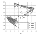
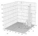
利用する色空間に限定はなく、L*a*b*やHSVなどを利用しても良いし、カラーカメラから得られるRGB値をそのまま使っても良い。図2に、赤信号、黄信号、及び青信号の色分布の一例を示す。これは昼間のサンプル画像から赤・黄・青の信号灯に含まれる画素を抽出し、各画素の値を、L*a*b*色空間に変換して、a*−b*の2次元平面上に投影した図である。青信号は他の2つの点灯色と明確に分離されているが、黄信号と赤信号は重複している部分があり分離が難しいことが分かる。また、このうち、赤信号の色分布をヒストグラム表現でデータ化したものを図3に示す。a*の−60〜80の範囲を14binに分割し、b*の−60〜100の範囲を16binに分割し、各binに対応する色領域に投票された画素数を頻度として表現している。 The color space to be used is not limited, and L * a * b * , HSV, or the like may be used, or RGB values obtained from a color camera may be used as they are. FIG. 2 shows an example of the color distribution of the red signal, the yellow signal, and the blue signal. This is a two-dimensional plane of a * -b * by extracting pixels included in red, yellow, and blue signal lights from daytime sample images and converting the values of each pixel to L * a * b * color space. It is the figure projected on the top. The blue signal is clearly separated from the other two lighting colors, but it can be seen that the yellow signal and the red signal have overlapping portions and are difficult to separate. Of these, FIG. 3 shows data obtained by converting the color distribution of the red signal into a histogram expression. The range of −60 to 80 of a * is divided into 14 bins, the range of −60 to 100 of b * is divided into 16 bins, and the number of pixels voted for the color area corresponding to each bin is expressed as a frequency. .
また、輝度の分布についても信号灯を撮像したサンプル画像から予め調査しておく。ただし、色分布データの学習で用いた色空間とは異なる色空間を用いて輝度を計算しても構わない。 The luminance distribution is also investigated in advance from a sample image obtained by imaging a signal lamp. However, the luminance may be calculated using a color space different from the color space used for learning the color distribution data.
上記の色分布データと輝度分布データを、点灯色毎に信号情報記憶部22に予め記憶しておく。
The color distribution data and the luminance distribution data are stored in advance in the signal
候補領域抽出部24は、取得した前方画像の画素(もしくはいくつかの小領域)ごとに学習時と同様の手順で色情報と輝度情報を抽出し、各画素について、抽出された色情報と輝度情報を、信号情報記憶部22に記憶された各点灯色の色分布データ及び輝度分布データと比較して、信号灯の候補であるかどうかを判定する。
The candidate
候補領域抽出部24は、信号灯の候補であると判定された画素が集中する領域を、信号灯候補として抽出し、抽出された信号灯候補の形状が円形であるか否かを判定する。円形度の算出は様々な方法があるが、ここでは以下の(1)式で計算し、例えばこの値が0.8〜1.2の間に入るものを円形であると判定する。
The candidate
ただし、Sは候補領域の面積、aは候補領域の幅、bは候補領域の高さを示す。 Where S is the area of the candidate region, a is the width of the candidate region, and b is the height of the candidate region.
また、候補領域抽出部24は、形状が円形であると判定された信号灯候補を、信号灯の候補領域として抽出する。また、候補領域抽出部24は、信号灯の候補領域として抽出された領域内の各画素の色情報及び輝度情報が、どの点灯色の色分布データ及び輝度分布データに当てはまるかによって、信号灯の候補領域の点灯色を検出する。
Further, the candidate
候補領域抽出部24は、上記の信号灯の候補領域の抽出を、連続して得られる前方画像の各々に対して繰り返し行う。
The candidate
追跡部26は、連続して抽出された信号灯の候補領域に対して、当該候補領域の色と輝度、形状に応じて対応付けを行い、信号灯の候補領域に対する追跡処理を行う。このとき、時間連続性を検証することにより、信号灯の候補領域の誤抽出を低減する。また、入力された前方画像間で信号灯の点灯色が変化しても、信号灯の候補領域の対応付けが可能なように、候補領域の大きさに基づいて、対応付けを行う照合範囲を動的に設定する。
The
切替判定部28は、追跡中の候補領域の位置変化に基づいて、信号灯の候補領域について、点灯色が切り替わったか否かを判定する。例えば、追跡中の信号灯の候補領域の位置が、不連続に変化した場合に、点灯色が切り替わったと判定する。このときに、センサ等により得られる自車両の運動情報を用いて、追跡中の信号灯の候補領域の位置が、不連続に変化したか否かを判定してもよい。また、追跡中の信号灯の候補領域の色情報が変化したか否かを更に考慮して、点灯色が切り替わったか否かを判定するようにしてもよい。
The switching
また、切替判定部28は、点灯色が切り替わったと判定した場合、信号灯の候補領域の色変化が信号灯の取り得る色変化であるか否かを判定する。すなわち、切替判定部28は、色変化が生じた場合に、追跡中の信号灯の候補領域の色変化が、信号灯の点灯規則と矛盾するかどうかを判定する。
Further, when it is determined that the lighting color has been switched, the switching
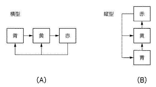
図4(A)又は図4(B)に示すとおりであり、縦型と横型の違いはあるが、灯器の配置と点灯順は予め決まっているため、点灯する信号灯の位置の変化に関する規則(右へ変化→右へ変化→左へ変化→右へ変化、又は上へ変化→上へ変化→下へ変化→上へ変化)及び点灯色の変化に関する規則(赤→黄→青→赤・・・)が、信号灯の点灯規則として予め定められている。例えば青信号の次は黄信号の点灯に限定され、ランプ位置は右もしくは上に移動する。 As shown in FIG. 4 (A) or FIG. 4 (B), there are differences between the vertical type and the horizontal type, but since the arrangement and lighting order of the lamps are determined in advance, the rules regarding the change in the position of the signal lamp to light (Right change → Change right → Change left → Change right or change up → Change up → Change down → Change up) and lighting color rules (red → yellow → blue → red ..) is predetermined as a lighting rule for signal lights. For example, after the blue signal, the lighting of the yellow signal is limited, and the lamp position moves to the right or up.
ここで、候補領域抽出部24において、黄信号と赤信号の認識を誤り、赤信号であると検出されたとする。このような場合、点灯規則に沿った変化でない(点灯規則との矛盾がある)と判定される。もし、候補領域抽出部24での検出結果も黄信号であれば、点灯規則に沿った変化である(点灯規則との矛盾はない)と判定される。
Here, it is assumed that the candidate
また、点灯色識別部30は、最終的な色の識別を行う。追跡中の信号灯の候補領域に対して色変化が生じていなければ、点灯色の切り替わりがなかったと判定し、点灯色識別部30は、前回識別された点灯色を、現像の信号灯の点灯色の識別結果として継続して保持する。
In addition, the lighting
点灯色識別部30は、切替判定部28によって、信号灯の候補領域の色変化が、点灯規則に沿った変化でない(点灯規則と検出結果に矛盾あり)と判定された場合には、両者の色の違いを検証するために、色空間における距離を算出する。例えば、L*a*b*色空間を利用する場合には、以下の(2)式を用いて、検出された画像中の候補領域の色情報と、点灯規則から予測される色情報(学習データ)との距離を算出する。
When the switching
ただし、添え字sは、現在の前方画像から計算される色情報であることを示し、rは信号情報記憶部22に記憶されている色分布データから得られる色情報であることを示す。
Here, the subscript s indicates color information calculated from the current front image, and r indicates color information obtained from the color distribution data stored in the signal
算出値rが閾値より小さければ、2つの色が近いため、信号灯の候補領域の抽出時に誤って点灯色が検出されたと判定し、点灯規則から推測される点灯色(点灯規則に沿って変化したときの点灯色)が、現在の信号灯の候補領域の点灯色であると識別する。一方、算出値rが閾値より大きい場合は、信号灯として有り得ない色変化をしており、信号灯の候補領域が信号灯を表わしていないと判断し、検出・追跡を中断する。 If the calculated value r is smaller than the threshold value, the two colors are close to each other, so it is determined that the lighting color is detected by mistake when extracting the candidate area of the signal light, and the lighting color estimated from the lighting rule (changed according to the lighting rule) The current lighting color) is identified as the lighting color of the current signal lamp candidate area. On the other hand, when the calculated value r is larger than the threshold value, it is determined that the color change is impossible as a signal light, and it is determined that the candidate area of the signal light does not represent the signal light, and detection / tracking is interrupted.
ここで、上記の閾値は図2に示したa*−b*空間で、赤信号のデータと黄信号のデータとの間の距離を許容し、その他の色(特に青)のデータとの距離を排除できる範囲で予め設定しておく。 Here, the above threshold value is the a * -b * space shown in FIG. 2, and allows the distance between the red signal data and the yellow signal data, and the distance from the other color (especially blue) data. Is set in advance within a range that can be eliminated.
また、点灯色識別部30は、前方画像からの信号灯の色の検出結果に誤りがあると判定した場合には、現在の信号灯の候補領域の色分布データを、一時的に色分布格納部32へ格納する。格納された色分布は、候補領域抽出部24による次回の抽出処理に利用されるとともに、切替判定部28において、次の点灯色への切替タイミングを判定するための参照データとして用いられる。また、色分布格納部32に格納された色分布データは、追跡中の信号灯の候補領域がフレームアウトして、前方画像から抽出されなくなるまでの間、保存され、追跡中の信号灯の候補領域がフレームアウトすると、色分布格納部32から色分布データが消去される。
In addition, when the lighting
また、点灯色識別部30は、切替判定部28によって、信号灯の候補領域の色変化が、点灯規則に沿った変化である(点灯規則と検出結果に矛盾なし)と判定された場合には、候補領域抽出部24で検出された点灯色を、現在の信号灯の点灯色として識別する。
Further, the lighting
また、点灯色識別部30は、信号灯の候補領域の点灯色の識別結果を、表示装置14に表示させる。
Further, the lighting
次に、第1の実施の形態に係る車載用信号灯識別装置10の作用について説明する。車載用信号灯識別装置10を搭載した自車両が道路上を走行しているときに、撮像装置12によって、自車両の前方が撮像されると、コンピュータ18において、図5に示す点灯色識別処理ルーチンが繰り返し実行される。
Next, the operation of the in-vehicle signal light identification device 10 according to the first embodiment will be described. When the front of the host vehicle is imaged by the
まず、ステップ100において、撮像装置12より撮像された前方画像を取得し、ステップ102において、上記ステップ100で取得した前方画像の各画素について、画素の色情報及び輝度情報と、信号情報記憶部22に記憶された各点灯色の色分布データ及び輝度分布データと比較することにより、信号灯の候補領域を抽出すると共に、信号灯の候補領域の点灯色を検出する。ここで、色分布格納部32に、少なくとも1色の点灯色の色分布データが格納されている場合には、信号情報記憶部22に記憶されている当該点灯色の色分布データに代えて、色分布格納部32に格納されている当該点灯色の色分布データを用いて、信号灯の候補領域を抽出する。
First, in
そして、ステップ104で、上記ステップ102で抽出された信号灯の候補領域と、前回抽出された信号灯の候補領域と対応付けることにより、信号灯の候補領域を追跡する。次のステップ106では、前回抽出された信号灯の候補領域が、フレームアウトしたか否かを判定する。上記ステップ104で、前回抽出された信号灯の候補領域と対応付けられる信号灯の候補領域がなく、信号灯の候補領域を追跡できなかった場合には、フレームアウトしたと判断し、ステップ108で、色分布格納部32に格納されている全ての色分布データを消去する。
In
そして、ステップ110において、前回抽出された信号灯の候補領域の位置及び色情報と、上記ステップ102で抽出された信号灯の候補領域の位置及び色情報とを比較して、点灯色が切り替わったか否かを判定する。点灯色が切り替わっていないと判定された場合には、ステップ112で、前回の処理で識別された点灯色の識別結果を維持して、現在の点灯色の識別結果とし、ステップ124へ移行する。
In
一方、上記ステップ110で点灯色が切り替わったと判定された場合には、ステップ113において、前回抽出された信号灯の候補領域と現在の信号灯の候補領域との位置及び色の変化が、点灯規則と矛盾しているか否かを判定する。信号灯の候補領域の位置及び色の変化が、点灯規則に沿った変化であり、矛盾していない場合には、ステップ114で、上記ステップ102で検出された点灯色を、現在の信号灯の点灯色として識別し、ステップ124へ移行する。
On the other hand, if it is determined in
一方、上記ステップ113において、信号灯の候補領域の位置及び色の変化が、点灯規則に沿った変化ではなく、矛盾していると判定された場合には、ステップ116において、上記(2)式に従って、信号灯の候補領域の色分布データから得られる平均的な色情報(a*値、b*値)と、信号情報記憶部22に記憶された、点灯規則に沿って変化した場合の点灯色の色分布データから得られる平均的な色情報(a*値、b*値)との、L*A*B*色空間での距離を算出し、算出された距離が、予め定められた閾値以下であるか否かを判定する。算出された距離が、閾値より大きい場合には、信号灯として有り得ない色変化をしていると判断し、ステップ118で、信号灯の候補領域が、信号灯ではないと判定し、ステップ124へ移行する。なお、この場合には、当該信号灯の候補領域に対する追跡処理は中止される。
On the other hand, if it is determined in
一方、上記ステップ116で、算出された距離が、閾値以下である場合には、点灯色の検出結果に誤りがあったと判断し、ステップ120で、信号灯の候補領域の色分布データを、色分布格納部32に一時的に格納する。そして、ステップ122において、点灯規則に沿って変化した場合の点灯色を、現在の信号灯の点灯色として識別し、ステップ124へ移行する。
On the other hand, if the calculated distance in
ステップ124では、上記ステップ112、114、又は122の識別結果を、表示装置14に表示させて、点灯色識別処理ルーチンを終了する。
In
上記の点灯色識別処理ルーチンが繰り返し実行されることにより、前方画像に表わされた信号灯が、追跡されると共に、点灯色の識別結果が逐次表示される。 By repeatedly executing the above-described lighting color identification processing routine, the signal light represented in the front image is tracked, and the identification result of the lighting color is sequentially displayed.
以上説明したように、第1の実施の形態に係る車載用信号灯識別装置によれば、撮像された前方画像から抽出された信号灯の候補領域について、点灯色が切り替わったと判定された場合に、点灯色の切り替わりによる信号灯の位置及び点灯色の変化に関する点灯規則に従って、信号灯の点灯色を識別することにより、前方画像が表わしている信号灯の点灯色を精度よく識別することができる。特に、赤信号と黄信号との誤認識を低減することができる。 As described above, according to the on-vehicle signal lamp identification device according to the first embodiment, when it is determined that the lighting color has been switched for the candidate area of the signal lamp extracted from the captured front image, the lighting is performed. By identifying the lighting color of the signal lamp according to the lighting rules regarding the position of the signal lamp and the change of the lighting color due to the color switching, the lighting color of the signal lamp represented by the front image can be accurately identified. In particular, misrecognition of a red signal and a yellow signal can be reduced.
信号灯の赤色と黄色は色空間上で近い位置に分布している。実際にカラーカメラで撮影した画像から赤信号と黄信号の色分布を調べてみると、両者の色分布が重複している。もともと近い色であることに加え、照明条件や汚れ、経年劣化の影響によりランプの輝度に個体差が生じることなどが原因と考えられる。このため、色情報に基づいて信号灯の色を識別する際に、黄色と赤色を間違えることがある。しかしながら、信号機は点灯する灯器の色の順番が決まっているので、本実施の形態では、信号灯の切り替わりを判定することによって、現在の点灯色が赤色であるのか黄色であるのかの検出結果を補正することが可能である。 The red and yellow signal lights are distributed at close positions in the color space. When the color distributions of the red signal and the yellow signal are examined from an image actually taken with a color camera, the color distributions of the two overlap. In addition to the colors that are close to each other, it is considered that there are individual differences in the brightness of the lamp due to the influence of lighting conditions, dirt, and deterioration over time. For this reason, when identifying the color of a signal light based on color information, yellow and red may be mistaken. However, since the order of the color of the lamps to be turned on is determined, in this embodiment, the detection result of whether the current lighting color is red or yellow is determined by determining the switching of the signal lights. It is possible to correct.
また、黄色であるのに赤色と判定された場合には、その色分布を黄色として一時的に保存する。そして、色分布の時間変化が小さい間は「黄信号」として認識する。追跡の結果から信号の切り替わりがなかったと判定されたことも合わせて、点灯色が継続していることを認識することができる。このように、点灯色の識別におけるロバスト性をさらに向上することができる。 If the color is determined to be red even though it is yellow, the color distribution is temporarily stored as yellow. When the time change of the color distribution is small, it is recognized as a “yellow signal”. It is possible to recognize that the lighting color continues together with the determination that the signal has not been switched from the tracking result. Thus, the robustness in identifying the lighting color can be further improved.
また、地図を使わず、撮像装置などの自律センサで信号灯を安定して認識することができる。 In addition, the signal light can be stably recognized by an autonomous sensor such as an imaging device without using a map.
なお、上記の実施の形態において、色分布格納部32に格納されるデータ形式に制約はないが、後述する第2の実施の形態におけるデータ統合のために、信号情報記憶部22のデータ形式に合わせておくと良い。
In the above embodiment, the data format stored in the color
また、上記(2)式は、以下の(3)式に示すように、輝度情報まで含めて距離を計算するように拡張しても構わない。 Further, the above equation (2) may be extended so as to calculate the distance including the luminance information as shown in the following equation (3).
また、切替判定部28と点灯色識別部30とを切り分けて説明したが、処理内容が共通している部分もあるので、切替判定部28と点灯色識別部30とを統合して構成することも可能である。例えば、切替判定部28において、色情報の変化を考慮する際に上記(2)式を用いるように構成してもよい。
In addition, the switching
また、点灯色が切り替わったと判定された時点で、色分布データを色分布格納部32に格納する場合を説明したが、これに限定されるものではなく、次に点灯色が切り替わったと判定されるまでの間であっても、信号灯の候補領域の色分布データが、信号情報記憶部22の色分布データと異なる場合に、色分布格納部32に格納する色分布データを更新してもよい。
Further, the case where the color distribution data is stored in the color
次に、第2の実施の形態について説明する。なお、第1の実施の形態と同様の構成となる部分については、同一符号を付して説明を省略する。 Next, a second embodiment will be described. In addition, about the part which becomes the structure similar to 1st Embodiment, the same code | symbol is attached | subjected and description is abbreviate | omitted.
第2の実施の形態では、一時的に格納した色分布データを蓄積して、信号情報記憶部に記憶された各点灯色の色分布データに反映している点が、第1の実施の形態と主に異なっている。 In the second embodiment, the color distribution data temporarily stored is accumulated and reflected in the color distribution data of each lighting color stored in the signal information storage unit. And mainly different.
図6に示すように、第2の実施の形態に係る車載用信号灯識別装置210のコンピュータ218は、画像入力部20と、信号情報記憶部22と、候補領域抽出部24と、追跡部26と、切替判定部28と、点灯色識別部30と、色分布格納部32と、色分布データを蓄積する色分布蓄積部234と、色分布格納部32に格納された色分布データを、色分布蓄積部234に蓄積すると共に、蓄積された色分布データに基づいて、信号情報記憶部22に記憶された信号灯の各点灯色の色分布データを更新する信号情報更新部236と、を備えている。
As shown in FIG. 6, the
色分布格納部32に色分布データが格納された後、当該色分布データを持つ信号灯が次の点灯色に切り替わった時点、もしくはフレームアウトして前方画像から抽出されなくなった時点で、当該色分布データは、色分布格納部32から信号情報更新部236に出力される。
After the color distribution data is stored in the color
信号情報更新部236は、色分布格納部32から出力された色分布データを規定の形式へと変換し、点灯色ごとに色分布蓄積部234へ逐次的に追加する。色分布のデータ形式は任意でよいが、ここでは、信号情報記憶部22と同じ形式(図3に示したヒストグラム形式)に変換するものとして説明する。同じ点灯色に対する色分布データの頻度を各bin毎に加算し、過去に入力された同じ点灯色の色分布データと現在の入力データを統合するように、色分布蓄積部234に、色分布データを蓄積する。ここで、データを統合する際、全体の頻度が1になるように正規化処理を施すことが望ましい。
The signal
統合した後で、ある点灯色について、色分布データが表わすヒストグラムの少なくとも1つのbinの頻度が規定値以上であれば、当該点灯色において、そのbinに相当する信号色が高い確率で検出されると判断し、信号情報記憶部22の当該点灯色に対する色分布データが表わすヒストグラムの、対応するbinの頻度を加算して更新する。
After integration, if the frequency of at least one bin in the histogram represented by the color distribution data for a certain lighting color is equal to or higher than a specified value, the signal color corresponding to that bin is detected with a high probability in that lighting color. The frequency of the corresponding bin in the histogram represented by the color distribution data for the lighting color in the signal
ここで、以下の(4)式に従って、加算率wを決定して、加算率wに応じて、頻度を加算する。 Here, the addition rate w is determined according to the following equation (4), and the frequency is added according to the addition rate w.
ただし、nは、加算対象のbinに蓄積されたデータの回数であり、fは、加算対象のbinに蓄積されたデータが表わす頻度の合計値であり、rは、信号情報記憶部22に記憶された当該点灯色の色分布データと加算対象のbinとの距離(色分布データにおいて頻度を有するbinのうち一番近いbinとの距離)である。また、上記の(4)式では、データの回数nが大きいほど、wの値が大きくなり、頻度の合計値fが大きいほど、wの値が大きくなり、色分布データとの距離rが大きくなるほど、wの値が小さくなるように、加算率wが決定される。
Here, n is the number of data accumulated in the bin to be added, f is a total value of frequencies represented by the data accumulated in the bin to be added, and r is stored in the signal
次に、第2の実施の形態に係る車載用信号灯識別装置210の作用について説明する。車載用信号灯識別装置210を搭載した自車両が道路上を走行しているときに、撮像装置12によって、自車両の前方が撮像されると、コンピュータ218において、第1の実施の形態と同様に点灯色識別処理ルーチンが繰り返し実行される。なお、上記ステップ108では、色分布格納部32に格納されている色分布データが全て消去されると共に、消去される全ての色分布データが色分布格納部32から出力される。
Next, the operation of the in-vehicle signal
また、コンピュータ218において、図7に示す信号情報更新処理ルーチンが実行される。
The
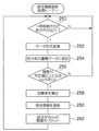
まず、ステップ250において、一時的に格納されていた色分布データが色分布格納部32から出力されたか否かを判定する。色分布データが色分布格納部32から出力されていない場合には、上記ステップ250へ戻るが、上記ステップ108で、色分布格納部32に格納されている色分布データが消去されると共に、当該色分布データが色分布格納部32から出力されると、当該色分布データを取得して、ステップ252へ進む。
First, in
ステップ252では、上記ステップ250で、色分布格納部32から出力された色分布データに対して、信号情報記憶部22の色分布データのデータ形式となるように、データ形式変換を行う。そして、ステップ254で、色分布蓄積部234に蓄積された、当該色分布データにおいて識別された点灯色に対応する色分布データに、上記ステップ252でデータ形式が変換された色分布データを統合する。すなわち、色分布蓄積部234に蓄積された、当該色分布データにおいて識別された点灯色に対応する色分布データに、上記ステップ252でデータ形式が変換された色分布データの各binの頻度を、bin毎に加算すると共に、正規化処理を行う。
In
そして、ステップ256において、上記ステップ256で蓄積された、当該点灯色に対応する色分布データのうち、頻度が所定値以上となるbinがあるか否かを判定する。どのbinも、頻度が所定値未満である場合には、上記ステップ250へ戻る。一方、上記ステップ256で、少なくとも1つのbinの頻度が所定値以上となった場合には、ステップ258で、上記(4)式に従って、頻度が所定値以上となったbinについて、加算率wを算出する。
In
そして、ステップ260において、上記ステップ258で算出された加算率wを用いて、蓄積された色分布データのうちの当該binにおける頻度の合計値を、信号情報記憶部22に記憶された当該点灯色の色分布データの当該binに加算して、信号情報記憶部22に記憶された当該点灯色の色分布データを更新する。
Then, in
次のステップ262では、色分布蓄積部234に蓄積された当該点灯色の色分布データにおいて、色分布データが更新されたbinの頻度を、リセットして、上記ステップ250へ戻る。
In the
以上説明したように、第2の実施の形態に係る車載用信号灯識別装置によれば、前方画像から得られる実際の信号灯の色分布に応じて、信号情報記憶部22の色分布データを更新することができるため、信号灯の抽出処理におけるロバスト性を向上させることができる。
As described above, according to the in-vehicle signal light identification device according to the second embodiment, the color distribution data in the signal
なお、上記の実施の形態では、色分布格納部32から信号情報更新部236へ色分布データを出力するタイミングを、対象の色分布を持つ信号灯が次の点灯色に切り替わるか、フレームアウトした時点としたが、これに限定されるものではなく、フレーム毎に色分布格納部32から信号情報更新部236へ色分布データを出力するようにしてもよい。また、色分布蓄積部234に蓄積するデータの個数(観測回数)を限定してもよいし、制限なく随時蓄積するようにしても良い。
In the above embodiment, the timing of outputting the color distribution data from the color
また、所定回数データを蓄積するごとに、色分布蓄積部234において、頻度の合計値が所定値より低いbinについては、リセットするようにしてもよい。
Further, every time data is accumulated a predetermined number of times, the color
また、上記の第1の実施の形態及び第2の実施の形態では、信号灯の点灯色の識別結果を表示装置に表示させる場合を例に説明したが、これに限定されるものではなく、信号灯の点灯色の識別結果を、運転介入制御などを行う運転支援システムに出力するようにしてもよい。 In the first embodiment and the second embodiment described above, the case where the identification result of the lighting color of the signal lamp is displayed on the display device is described as an example. However, the present invention is not limited to this. The identification result of the lighting color may be output to a driving support system that performs driving intervention control or the like.
また、候補領域抽出部24において、候補領域の高さなどの3次元位置を更に考慮して、信号灯の候補領域を抽出するようにしてもよい。
Further, the candidate
また、候補領域抽出部24において、形状(パターン)に基づいて信号機全体の領域も抽出し、切替判定部28において、信号機全体の領域と点灯中のランプ(高輝度領域)との相対位置の変化から点灯色の切り替わりを判定してもよい。また、信号機全体の領域に対する点灯ランプの相対位置も考慮することで、認識した点灯色の誤りを判定するようにしてもよい。
In addition, the candidate
本発明のプログラムを、記憶媒体に格納して提供することも可能である。 It is also possible to provide the program of the present invention by storing it in a storage medium.
10、210 車載用信号灯識別装置
12 撮像装置
18、218 コンピュータ
22 信号情報記憶部
24 候補領域抽出部
26 追跡部
28 切替判定部
30 点灯色識別部
32 色分布格納部
234 色分布蓄積部
236 信号情報更新部
DESCRIPTION OF SYMBOLS 10,210 Vehicle signal
Claims (9)
前記追跡された前記信号灯の候補領域の位置の変化から、点灯色の切り替わりを判定する切替判定手段と、
前記判定手段によって点灯色が切り替わったと判定された場合、点灯色が切り替わったときの前記信号灯の候補領域の位置及び色の変化が、予め定められた点灯色の切り替わりによる信号灯の位置及び点灯色の変化に関する規則に沿った変化であるか否かを判定する変化規則判定手段と、
前記変化規則判定手段によって、前記信号灯の候補領域の位置及び色の変化が、前記規則に沿った変化でないと判定された場合、前記規則に沿って変化したときの点灯色を、前記信号灯の候補領域の点灯色として識別する点灯色識別手段と、
を含む点灯色識別装置。 Based on color information of each lighting color of a predetermined signal lamp from a captured image captured by an imaging device that captures the periphery of the host vehicle, the signal lamp candidate area is repeatedly extracted and the corresponding signal lamp candidate Candidate area extraction means for tracking the area;
From a change in the position of the tracked candidate area of the signal light, switching determination means for determining switching of the lighting color,
When it is determined that the lighting color has been switched by the determining means, the position and color change of the candidate area of the signal lamp when the lighting color is switched are the position of the signal lamp and the lighting color by the predetermined lighting color switching. Change rule determining means for determining whether or not the change is in accordance with a change rule;
When the change rule determining means determines that the change in the position and color of the candidate area of the signal light is not a change in accordance with the rule, the lighting color when the change in the rule is changed is determined as the candidate for the signal light. A lighting color identification means for identifying the lighting color of the area;
Lighting color identification device including
前記候補領域抽出手段は、前記撮像画像から、前記色情報格納手段に格納された前記点灯色の色情報を用いて、前記信号灯の候補領域を繰り返し抽出すると共に、対応する信号灯の候補領域を追跡する請求項1記載の点灯色識別装置。 When the change rule determining means determines that the change in the position and color of the signal lamp candidate area is not a change in accordance with the rule, the color information of the signal lamp candidate area has been changed in accordance with the rule. Storage control means for storing in the color information storage means as the color information of the lighting color at the time,
The candidate area extraction unit repeatedly extracts the signal lamp candidate area from the captured image using the color information of the lighting color stored in the color information storage unit, and tracks the corresponding signal lamp candidate area. The lighting color identification device according to claim 1.
前記色情報格納手段に格納した前記点灯色のヒストグラムが示す各色成分の頻度を、各点灯色について合計し、何れかの点灯色のヒストグラムについて、何れかの前記色成分の前記頻度の合計値が所定値以上となった場合、該点灯色のヒストグラムの該色成分の前記頻度の合計値に基づいて、前記色情報記憶手段に記憶された該点灯色のヒストグラムが示す該色成分の頻度を更新する色情報更新手段とを更に含み、
前記候補領域抽出手段は、前記撮像画像から、前記色情報記憶手段に記憶された各点灯色の前記色情報に基づいて、信号灯の候補領域を繰り返し抽出すると共に、対応する信号灯の候補領域を追跡する請求項2又は3記載の点灯色識別装置。 Color information storage means for storing the color information representing a histogram indicating the frequency of each color component for each lighting color;
The frequency of each color component indicated by the lighting color histogram stored in the color information storage means is totaled for each lighting color, and for any lighting color histogram, the total value of the frequencies of any of the color components is When the predetermined value or more is reached, the frequency of the color component indicated by the lighting color histogram stored in the color information storage means is updated based on the total frequency of the color components of the lighting color histogram. Color information updating means for performing,
The candidate area extracting unit repeatedly extracts a signal lamp candidate area from the captured image based on the color information of each lighting color stored in the color information storage unit, and tracks the corresponding signal lamp candidate area. The lighting color identification device according to claim 2 or 3.
前記点灯色識別手段は、前記変化規則判定手段によって、前記信号灯の候補領域の位置及び色の変化が、前記規則に沿った変化でないと判定された場合であって、かつ、前記距離判定手段によって算出された前記距離が前記所定値未満である場合に、前記規則に沿って変化したときの点灯色を、前記信号灯の候補領域の点灯色として識別する請求項1〜請求項5の何れか1項記載の点灯色識別装置。 When the change rule determining means determines that the position and color change of the candidate area of the signal light is not a change according to the rule, the color information of the lighting color when changed according to the rule; and A distance determination unit that calculates a distance from the color information of the candidate area of the signal lamp, and determines that the candidate area of the signal lamp does not represent the signal lamp if the calculated distance is equal to or greater than a predetermined value;
The lighting color identifying means is a case where the change rule determining means determines that the change in the position and color of the candidate area of the signal light is not a change according to the rule, and the distance determining means When the calculated distance is less than the predetermined value, a lighting color when changing according to the rule is identified as a lighting color of the candidate area of the signal lamp. The lighting color identification device according to item.
前記点灯色識別手段は、前記変化規則判定手段によって、前記信号灯の候補領域の位置及び色の変化が、前記規則に沿った変化であると判定された場合、前記候補領域抽出手段において検出された点灯色を、前記信号灯の候補領域の点灯色として識別する請求項1〜請求項7の何れか1項記載の点灯色識別装置。 The candidate area extracting means extracts the signal lamp candidate area from the captured image and detects the lighting color of the signal lamp candidate area,
The lighting color identifying means is detected by the candidate area extracting means when the change rule determining means determines that the change in the position and color of the candidate area of the signal light is a change according to the rule. The lighting color identification device according to any one of claims 1 to 7, wherein a lighting color is identified as a lighting color of a candidate area of the signal lamp.
自車両の周辺を撮像する撮像装置によって撮像された撮像画像から、予め定められた信号灯の各点灯色の色情報に基づいて、前記信号灯の候補領域を繰り返し抽出すると共に、対応する前記信号灯の候補領域を追跡する候補領域抽出手段、
前記追跡された前記信号灯の候補領域の位置の変化から、点灯色の切り替わりを判定する切替判定手段、
前記判定手段によって点灯色が切り替わったと判定された場合、点灯色が切り替わったときの前記信号灯の候補領域の位置及び色の変化が、予め定められた点灯色の切り替わりによる信号灯の位置及び点灯色の変化に関する規則に沿った変化であるか否かを判定する変化規則判定手段、及び
前記変化規則判定手段によって、前記信号灯の候補領域の位置及び色の変化が、前記規則に沿った変化でないと判定された場合、前記規則に沿って変化したときの点灯色を、前記信号灯の候補領域の点灯色として識別する点灯色識別手段
として機能させるためのプログラム。 Computer
Based on color information of each lighting color of a predetermined signal lamp from a captured image captured by an imaging device that captures the periphery of the host vehicle, the signal lamp candidate area is repeatedly extracted and the corresponding signal lamp candidate Candidate area extraction means for tracking the area;
From a change in the position of the tracked candidate area of the signal light, a switching determination means for determining switching of the lighting color,
When it is determined that the lighting color has been switched by the determining means, the position and color change of the candidate area of the signal lamp when the lighting color is switched are the position of the signal lamp and the lighting color by the predetermined lighting color switching. A change rule determining unit that determines whether or not the change is in accordance with a change rule; and the change rule determining unit determines that the change in position and color of the candidate area of the signal light is not a change in accordance with the rule. If so, a program for causing a lighting color when changing according to the rule to function as a lighting color identification means for identifying the lighting color of the candidate area of the signal light.
Priority Applications (1)
| Application Number | Priority Date | Filing Date | Title |
|---|---|---|---|
| JP2010032674A JP5407920B2 (en) | 2010-02-17 | 2010-02-17 | Lighting color identification device and program |
Applications Claiming Priority (1)
| Application Number | Priority Date | Filing Date | Title |
|---|---|---|---|
| JP2010032674A JP5407920B2 (en) | 2010-02-17 | 2010-02-17 | Lighting color identification device and program |
Publications (2)
| Publication Number | Publication Date |
|---|---|
| JP2011170539A JP2011170539A (en) | 2011-09-01 |
| JP5407920B2 true JP5407920B2 (en) | 2014-02-05 |
Family
ID=44684617
Family Applications (1)
| Application Number | Title | Priority Date | Filing Date |
|---|---|---|---|
| JP2010032674A Expired - Fee Related JP5407920B2 (en) | 2010-02-17 | 2010-02-17 | Lighting color identification device and program |
Country Status (1)
| Country | Link |
|---|---|
| JP (1) | JP5407920B2 (en) |
Families Citing this family (7)
| Publication number | Priority date | Publication date | Assignee | Title |
|---|---|---|---|---|
| CN102663892B (en) * | 2012-05-29 | 2014-01-22 | 四川川大智胜软件股份有限公司 | Method for correcting discoloration and enlarging of red light in night red-light-running vehicle picture |
| US9373046B2 (en) * | 2014-09-10 | 2016-06-21 | Continental Automotive Systems, Inc. | Detection system for color blind drivers |
| KR102248673B1 (en) * | 2020-01-07 | 2021-05-06 | 주식회사 에프에스솔루션 | Method for identificating traffic lights, device and program using the same |
| CN112528795A (en) | 2020-12-03 | 2021-03-19 | 北京百度网讯科技有限公司 | Signal lamp color identification method and device and road side equipment |
| CN112633137B (en) * | 2020-12-18 | 2024-12-13 | 浙江大华技术股份有限公司 | Signal light state correction method, device and computer readable storage medium |
| CN113723229B (en) * | 2021-08-16 | 2024-11-08 | 浙江大华技术股份有限公司 | Signal light detection method, device and computer readable storage medium |
| JP7317081B2 (en) | 2021-08-23 | 2023-07-28 | 本田技研工業株式会社 | Progress/Stop Judgment Device |
Family Cites Families (4)
| Publication number | Priority date | Publication date | Assignee | Title |
|---|---|---|---|---|
| JP2005301519A (en) * | 2004-04-08 | 2005-10-27 | Toyota Motor Corp | Traffic signal detection apparatus and traffic signal detection method |
| JP4577153B2 (en) * | 2005-08-24 | 2010-11-10 | 株式会社デンソー | Environment recognition device |
| JP2009015759A (en) * | 2007-07-09 | 2009-01-22 | Honda Motor Co Ltd | Traffic light recognition device |
| JP2009230560A (en) * | 2008-03-24 | 2009-10-08 | Casio Comput Co Ltd | Signal recognition device and signal recognition processing program |
-
2010
- 2010-02-17 JP JP2010032674A patent/JP5407920B2/en not_active Expired - Fee Related
Also Published As
| Publication number | Publication date |
|---|---|
| JP2011170539A (en) | 2011-09-01 |
Similar Documents
| Publication | Publication Date | Title |
|---|---|---|
| JP5747549B2 (en) | Signal detector and program | |
| JP5407920B2 (en) | Lighting color identification device and program | |
| US9317757B2 (en) | Method and apparatus for detecting a rear vehicle light | |
| US8848980B2 (en) | Front vehicle detecting method and front vehicle detecting apparatus | |
| US20130286205A1 (en) | Approaching object detection device and method for detecting approaching objects | |
| US8199971B2 (en) | Object detection system with improved object detection accuracy | |
| US9493108B2 (en) | Apparatus for detecting other vehicle lights and light control apparatus for vehicles | |
| JP4872769B2 (en) | Road surface discrimination device and road surface discrimination method | |
| US9619895B2 (en) | Image processing method of vehicle camera and image processing apparatus using the same | |
| JP5065172B2 (en) | Vehicle lighting determination device and program | |
| JP4930046B2 (en) | Road surface discrimination method and road surface discrimination device | |
| JP2018190082A (en) | Vehicle type identification device, vehicle type identification method, and vehicle type identification system | |
| JP5780979B2 (en) | Vehicle state detection device, vehicle behavior detection device, and vehicle state detection method | |
| JP2014160408A (en) | Road sign recognition device | |
| JP2010286995A (en) | Image processing system for vehicle | |
| JP5353531B2 (en) | Vehicle light recognition device and program | |
| JP4674179B2 (en) | Shadow recognition method and shadow boundary extraction method | |
| JP5327241B2 (en) | Object identification device | |
| JP2018073049A (en) | Image recognition device, image recognition system, and image recognition method | |
| JP4762026B2 (en) | Road sign database construction device | |
| CN111090096B (en) | Night vehicle detection method, device and system | |
| US20240312220A1 (en) | Image processing device, image processing method, and program | |
| JP2010015235A (en) | Pedestrian detector and program | |
| JP5310162B2 (en) | Vehicle lighting judgment device | |
| KR101959193B1 (en) | Apparatus for detecting inter-vehicle distance using lamp image and Method for detecting inter-vehicle distance using the same |
Legal Events
| Date | Code | Title | Description |
|---|---|---|---|
| A621 | Written request for application examination |
Free format text: JAPANESE INTERMEDIATE CODE: A621 Effective date: 20121102 |
|
| TRDD | Decision of grant or rejection written | ||
| A01 | Written decision to grant a patent or to grant a registration (utility model) |
Free format text: JAPANESE INTERMEDIATE CODE: A01 Effective date: 20131008 |
|
| A977 | Report on retrieval |
Free format text: JAPANESE INTERMEDIATE CODE: A971007 Effective date: 20131009 |
|
| A61 | First payment of annual fees (during grant procedure) |
Free format text: JAPANESE INTERMEDIATE CODE: A61 Effective date: 20131021 |
|
| R151 | Written notification of patent or utility model registration |
Ref document number: 5407920 Country of ref document: JP Free format text: JAPANESE INTERMEDIATE CODE: R151 |
|
| LAPS | Cancellation because of no payment of annual fees |