JP5407913B2 - Drive control device - Google Patents
Drive control device Download PDFInfo
- Publication number
- JP5407913B2 JP5407913B2 JP2010023282A JP2010023282A JP5407913B2 JP 5407913 B2 JP5407913 B2 JP 5407913B2 JP 2010023282 A JP2010023282 A JP 2010023282A JP 2010023282 A JP2010023282 A JP 2010023282A JP 5407913 B2 JP5407913 B2 JP 5407913B2
- Authority
- JP
- Japan
- Prior art keywords
- vehicle
- learning
- state information
- degree
- learned
- Prior art date
- Legal status (The legal status is an assumption and is not a legal conclusion. Google has not performed a legal analysis and makes no representation as to the accuracy of the status listed.)
- Expired - Fee Related
Links
Images


Landscapes
- Control Of Driving Devices And Active Controlling Of Vehicle (AREA)
- Combined Controls Of Internal Combustion Engines (AREA)
- Traffic Control Systems (AREA)
Description
本発明は、例えば自動車等の車両の挙動を学習し、該学習された挙動に応じて車両を制御する駆動制御装置の技術分野に関する。 The present invention relates to a technical field of a drive control device that learns the behavior of a vehicle such as an automobile and controls the vehicle according to the learned behavior.
この種の装置として、例えば、検出された自車両の挙動と、当該挙動の検出より前に認識された対象地物と、の関係を表わす関係情報を取得し、検出された自車両の挙動の属性を表わす挙動属性情報と、当該挙動について取得された関係情報と、を含む検出挙動情報を記憶し、該記憶された検出挙動情報に基づいて、対象地物と関連付けられた自車両の挙動の学習結果を表わす学習挙動情報を生成する装置が提案されている(特許文献1参照)。 As this type of device, for example, the relationship information representing the relationship between the detected behavior of the own vehicle and the target feature recognized before the detection of the behavior is acquired, and the detected behavior of the own vehicle is acquired. Detection behavior information including behavior attribute information representing an attribute and relation information acquired for the behavior is stored, and based on the stored detection behavior information, the behavior of the vehicle associated with the target feature is stored. An apparatus for generating learning behavior information representing a learning result has been proposed (see Patent Document 1).
しかしながら、上述の背景技術では、状況によっては、学習された挙動に基づいて車両の制御を行うと、該車両の運転者に違和感を与える可能性があるという技術的問題点がある。 However, in the above-described background art, there is a technical problem that depending on the situation, if the vehicle is controlled based on the learned behavior, the driver of the vehicle may be uncomfortable.
本発明は、例えば上記問題点に鑑みてなされたものであり、車両の制御に起因する運転者の違和感を低減することができる駆動制御装置を提案することを課題とする。 The present invention has been made in view of the above-described problems, for example, and an object of the present invention is to propose a drive control device that can reduce a driver's uncomfortable feeling caused by vehicle control.
本発明の駆動制御装置は、上記課題を解決するために、車両に搭載され、前記車両の走行状態に係る情報である走行状態情報を、前記車両が走行している位置に係る情報である位置情報に関連付けて学習する学習手段と、前記学習された走行状態情報に応じて、前記学習された走行状態情報を前記車両の駆動制御に用いる際の度合いを決定する決定手段とを備え、前記決定手段は、前記学習された走行状態情報の傾向及びばらつきに基づいて、前記学習された走行状態情報の自信度を算出する算出手段を含み、前記算出された自信度に基づいて、前記学習された走行状態情報を前記車両の駆動制御に用いる際の度合いを決定する。 In order to solve the above-described problem, the drive control device of the present invention is mounted on a vehicle, and travel state information, which is information related to the travel state of the vehicle, is used as a position that is information related to a position where the vehicle is traveling. and learning means for learning in association with information, in response to said learned travel condition information, running state information the learned and a determining means for determining a degree when used for the drive control of the vehicle, said determining The means includes calculation means for calculating a degree of confidence of the learned driving state information based on a tendency and variation of the learned driving state information, and the learning is performed based on the calculated degree of confidence. A degree at which the traveling state information is used for driving control of the vehicle is determined .
本発明の駆動制御装置によれば、当該駆動制御装置は、例えば自動車等の車両に搭載されている。例えばメモリ、プロセッサ等を備えてなる学習手段は、車両の走行状態に係る情報である走行状態情報を、車両が走行している位置に係る情報である位置情報に関連付けて学習する。 According to the drive control device of the present invention, the drive control device is mounted on a vehicle such as an automobile. For example, a learning unit including a memory, a processor, and the like learns driving state information that is information related to a driving state of the vehicle in association with position information that is information related to a position where the vehicle is driving.
尚、位置情報は、例えばGPS(Global Positioning System)、INS(Inertial Navigation System)、マップマッチング等の公知の技術を利用して求めればよい。 The position information may be obtained by using known techniques such as GPS (Global Positioning System), INS (Internal Navigation System), map matching, and the like.
例えばメモリ、プロセッサ等を備えてなる決定手段は、学習された走行状態情報に応じて、該学習された走行状態情報を車両の駆動制御に用いる際の度合いを決定する。ここで、「度合い」は、学習された走行状態情報が、どの程度車両の駆動制御に反映されるかを示す指標であり、例えば「自信度」、「信頼度」、「優先度」、「重要度」等と読み替えることができる。例えば、「度合い」が大きい程、学習された走行状態情報が車両の駆動制御に反映される可能性が高くなる。 For example, a determination unit including a memory, a processor, and the like determines a degree at which the learned traveling state information is used for vehicle drive control according to the learned traveling state information. Here, “degree” is an index indicating how much the learned driving state information is reflected in the drive control of the vehicle. For example, “degree of confidence”, “reliability”, “priority”, “ It can be read as “importance”. For example, the greater the “degree”, the higher the possibility that the learned travel state information is reflected in the drive control of the vehicle.
尚、「度合い」は、具体的な数値で表わされることに限らず、例えば、“A”、“B”、“C”、…等の文字や記号等で表わされていてもよい。 The “degree” is not limited to a specific numerical value, and may be expressed by a character or symbol such as “A”, “B”, “C”,.
本願発明者の研究によれば、以下の事項が判明している。即ち、将来の状態がわからない場合、瞬時最適制御が行われることが多いが、必ずしも最適な制御が行われるとは限らない。また、カーナビゲーション装置との協調が図られる制御であるNAVI・AI−SHIFT制御では、車両の走行場所によっては十分な効果が得られないおそれがある。また、学習データに基づいて車両の制御が行われる場合、学習データの質によっては、制御に起因して運転者に違和感を与えるおそれがある。加えて、現実問題として、学習データに基づく将来の走行パターンの推測を、あらゆる場所で100%の精度で実施することは不可能である。 According to the inventor's research, the following matters have been found. That is, when the future state is not known, instantaneous optimal control is often performed, but optimal control is not always performed. Further, in NAVI / AI-SHIFT control, which is control that can be coordinated with the car navigation device, there is a possibility that a sufficient effect may not be obtained depending on the travel location of the vehicle. Further, when the vehicle is controlled based on the learning data, the driver may feel uncomfortable due to the control depending on the quality of the learning data. In addition, as a real problem, it is impossible to estimate the future driving pattern based on the learning data with 100% accuracy in every place.
しかるに本発明では、決定手段により、学習された走行状態情報に応じて、該学習された走行状態情報を車両の駆動制御に用いる際の度合いが決定される。このため、車両の駆動制御には、度合いが比較的大きい(即ち、十分学習された)走行状態情報が反映されるので、駆動制御に起因して運転者に違和感を与える可能性を抑制することができる。他方、度合いが比較的小さい(即ち、例えば学習が十分ではなく走行状態情報の質が比較的低い)場合は、例えば、走行状態情報を駆動制御に反映させることに代えて、瞬時最適制御等を行うことによって、度合いが比較的小さい走行状態情報を用いた駆動制御よりは、運転者に違和感を与える可能性を抑制することができる。 In the present invention, however, the degree of use of the learned traveling state information for vehicle drive control is determined by the determining means in accordance with the learned traveling state information. For this reason, since the driving state information of the vehicle reflects relatively large (that is, sufficiently learned) driving state information, the possibility of giving the driver a sense of incongruity due to the driving control is suppressed. Can do. On the other hand, when the degree is relatively small (that is, for example, learning is not sufficient and the quality of the traveling state information is relatively low), for example, instead of reflecting the traveling state information in the drive control, instantaneous optimal control or the like is performed. By performing, it is possible to suppress the possibility of giving the driver a sense of incongruity as compared with drive control using travel state information with a relatively low degree.
以上の結果、本発明の駆動制御装置によれば、車両の駆動制御に起因する運転者の違和感を低減することができる。更に、学習データに基づく駆動制御を実施可能な地域を拡大することができる。
本発明では特に、前記決定手段は、前記学習された走行状態情報の傾向及びばらつきに基づいて、前記学習された走行状態情報の自信度を算出する算出手段を含み、前記算出された自信度に基づいて、前記学習された走行状態情報を前記車両の駆動制御に用いる際の度合いを決定する。
例えばメモリ、プロセッサ等を備えてなる算出手段は、学習された走行状態情報の傾向及びばらつきに基づいて、学習された走行状態情報の自信度を算出する。ここで、自信度は、例えばカルマンフィルタ等の公知の方法により求めればよい。尚、「走行状態情報の傾向」は、例えば、走行状態情報に含まれる複数回分の学習データ相互間の相関性を意味する。決定手段は、算出された自信度に基づいて、学習された走行状態情報を車両の駆動制御に用いる際の度合いを決定する。このため、比較的容易にして度合いを決定することができ、実用上非常に有利である。
As a result, according to the drive control device of the present invention, it is possible to reduce the driver's uncomfortable feeling due to the drive control of the vehicle. Furthermore, the area where drive control based on learning data can be performed can be expanded.
Particularly in the present invention, the determining means includes a calculating means for calculating a confidence level of the learned driving state information based on a tendency and a variation of the learned driving state information, and the calculated confidence level includes Based on this, the degree of use of the learned driving state information for driving control of the vehicle is determined.
For example, a calculation unit including a memory, a processor, and the like calculates the confidence level of the learned traveling state information based on the tendency and variation of the learned traveling state information. Here, the confidence level may be obtained by a known method such as a Kalman filter. The “trend of running state information” means, for example, the correlation between learning data for a plurality of times included in the running state information. The determining means determines a degree at which the learned traveling state information is used for driving control of the vehicle based on the calculated degree of confidence. Therefore, the degree can be determined relatively easily, which is very advantageous in practice.
本発明の作用及び他の利得は次に説明する実施するための形態から明らかにされる。 The effect | action and other gain of this invention are clarified from the form for implementing demonstrated below.
以下、本発明に係る駆動制御装置の実施形態について、図1乃至図8を参照して説明する。 Embodiments of a drive control apparatus according to the present invention will be described below with reference to FIGS.
先ず、本実施形態に係る駆動制御装置の構成について、図1を参照して説明する。図1は、本実施形態に係る駆動制御装置の構成を示すブロック図である。尚、図1では、説明の便宜上、本実施形態に直接関係のある部材のみ図示しており、他の部材については図示を省略している。また、図1中における矢印は、信号の流れを示している。 First, the configuration of the drive control apparatus according to the present embodiment will be described with reference to FIG. FIG. 1 is a block diagram showing the configuration of the drive control apparatus according to the present embodiment. In FIG. 1, for convenience of explanation, only members that are directly related to the present embodiment are shown, and other members are not shown. Moreover, the arrow in FIG. 1 has shown the flow of the signal.
図1において、駆動制御装置100は、車両1に搭載されている。駆動制御装置100は、測位演算部11、学習処理部12、学習データ蓄積部13、推測演算部14、推測自信度演算部15、制御実施自信度演算部16、瞬時最適車両制御部17、先読み車両制御部18及び調停部19を備えて構成されている。
In FIG. 1, the
測位演算部11は、例えばGPS、INS、マップマッチング等により、車両1の測位演算を行うと共に、例えばGPS、INS、マップマッチング等の自信度(精度)を考慮して、例えばカルマンフィルタ等の公知の方法を用いて最終的な車両1の位置の自信度を算出する。測位演算部11は、車両1の位置を示す信号を、学習処理部12に送信すると共に、車両1の位置の自信度を示す信号を、制御実施自信度演算部16に送信する。
The positioning calculation unit 11 performs positioning calculation of the
学習処理部12は、例えば、車速センサ、加速度センサ、ヨーレートセンサ、アクセルポジションセンサ等の各種センサから出力された信号により示される各種物理量又はパラメータ(即ち、走行状態情報)を、測位演算部11から出力された信号により示される車両1の位置(即ち、位置情報)に関連付けて学習する。
The
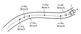
ここで、学習処理部12における学習の一例について、図2を参照して説明を加える。図2は、本実施形態に係る学習の概念の一例を示す概念図である。図2では、車速の学習を例として挙げる。
Here, an example of learning in the
図2に示すように、学習処理部12は、例えば、道路形状を規定する地点であるノードa〜fの各々において、車速センサから出力された信号により示された車速を、夫々、測位演算部11から出力された信号により示されるノードa〜fの各々の位置に関連付けて学習する。
As shown in FIG. 2, for example, the
このように学習すれば、数値として表現することが比較的困難な道路固有の状況に応じた車両1の運転者の操作を学習することができる。このため、例えば、画像処理を用いて道幅や見通しの状況を把握する等の必要がなく、実用上非常に有利である。
By learning in this way, it is possible to learn the operation of the driver of the
再び図1に戻り、学習データ蓄積部13は、学習処理部12により学習された学習データを蓄積する。また、学習データ蓄積部13は、蓄積された学習データ(即ち、過去の走行パターン)を示す信号を推測演算部14に送信する。更に、学習データ蓄積部13は、学習データの学習回数や学習データのばらつきを示す信号を推測自信度演算部15に送信する。
Returning to FIG. 1 again, the learning
推測演算部14は、学習データ蓄積部13から出力された信号により示される学習データに基づいて、車両1の将来の走行状態を推測する。具体的には例えば、車両1の現在位置よりも100m(メートル)先の位置における車速が推測される場合、次のような数式により車速が推測される。
V推定(100m先)=Vメモリ(100m先)×V(現在位置)÷Vメモリ(現在位置)
つまり、学習データにより示される100m先の位置における車速に、現在位置における実際の車速と学習データにより示される車速との比をかけることにより100m先の位置における車速が推測される。
The
V estimation (100m ahead) = V memory (100m ahead) x V (current position) ÷ V memory (current position)
That is, the vehicle speed at the position 100 m ahead is estimated by multiplying the vehicle speed at the position 100 m ahead indicated by the learning data by the ratio of the actual vehicle speed at the current position and the vehicle speed indicated by the learning data.
推測自信度演算部15は、例えば、車速センサ、加速度センサ、ヨーレートセンサ、アクセルポジションセンサ等の各種センサから出力された信号により示される各種物理量又はパラメータと、学習データ蓄積部13から出力された信号により示される学習データの学習回数やばらつきと、に基づいて学習データの自信度を演算し、以って推測演算部14により推測された物理量又はパラメータ(即ち、推測情報)の自信度を求める。
The estimated confidence
具体的には例えば、推測自信度演算部15は、学習データの学習回数と、学習データのばらつきとの二軸からなる自信度算出マップに基づいて、学習自信度を求める。また、推測自信度演算部15は、学習データにより示される過去の走行パターンと、今回の走行パターンとの相関性に応じて、例えば図3に示すようなマップから学習利用自信度を求める。そして、推測自信度演算部15は、学習自信度と学習利用自信度とに基づいて、学習データの自信度を演算する。
Specifically, for example, the estimated confidence
仮に相関性を利用しないとすると、例えば過去の走行パターンと車速が誤差範囲を超えて異なる場合(例えば先行車両が存在する場合等)(図4参照)、学習データを利用することができない。しかるに本実施形態では相関線を利用しているので、例えば過去の走行パターンと車速が誤差範囲を超えて異なる場合であっても、学習データを利用することができ、後述するような駆動制御を行うことができる。 If the correlation is not used, for example, when the past travel pattern and the vehicle speed are different from each other beyond the error range (for example, when a preceding vehicle exists) (see FIG. 4), the learning data cannot be used. However, since the correlation line is used in the present embodiment, for example, even when the past traveling pattern and the vehicle speed differ beyond the error range, the learning data can be used, and drive control as described later is performed. It can be carried out.
尚、図3は、学習利用自信度算出マップの一例であり、図4は、過去の走行パターンと今回の走行パターンとの関係の一例を示す概念図である。 FIG. 3 is an example of the learning use confidence level calculation map, and FIG. 4 is a conceptual diagram showing an example of the relationship between the past travel pattern and the current travel pattern.
制御実施自信度演算部16は、測位演算部11から出力された信号により示される位置情報の自信度と、推測自信度演算部15から出力された信号により示される推測情報の自信度とに基づいて、例えば図5に示すようなマップから制御実施自信度を求める。マップを用いることにより、駆動制御装置100の計算負荷を低減することができ、実用上非常に有利である。
The control execution confidence
図5は、制御実施自信度算出マップの一例である。尚、このようなマップは、実験的若しくは経験的、又はシミュレーションによって、例えば位置情報及び推測情報の悪化がどの程度車両制御に影響を与えるかを求め、その結果に基づいて構築すればよい。 FIG. 5 is an example of a control execution confidence calculation map. Such a map may be constructed based on the results obtained by determining how much the deterioration of the position information and the estimated information affects the vehicle control, for example, experimentally, empirically, or by simulation.
瞬時最適車両制御部17は、例えば、車速センサ、加速度センサ、ヨーレートセンサ、アクセルポジションセンサ等の各種センサから出力された信号により示される各種物理量又はパラメータに基づいて、現在の車両1の走行状態に応じた最適な物理量又はパラメータを出力する。
The instantaneous optimum vehicle control unit 17 determines the current running state of the
先読み車両制御部18は、推測演算部14から出力された信号により示される車両1の将来の走行状態に応じた物理量又はパラメータを出力する。
The look-ahead vehicle control unit 18 outputs a physical quantity or parameter corresponding to the future traveling state of the
具体的には例えば、先読み車両制御部18は、図6に示すような、比較的短い直線区間(即ち、加速区間)を、ハイブリッド車両である車両1が走行する場合、加速区間を車両1の駆動用のモータのみで走行するように(即ち、加速区間においてエンジンが始動されないように)、エンジンの始動に係るパラメータ(又は閾値)を変更して出力する。この結果、燃費効率の向上を図ることができる。
Specifically, for example, when the
或いは、先読み車両制御部18は、ハイブリッド車両である車両1が曲線区間に進入する場合、図7(a)に示すように、回生ブレーキが作動するタイミングが比較的早くなるように、回生ブレーキに係るパラメータを変更して出力する。尚、車両1の運転者は、図7中の地点P1で、ブレーキペダルを踏下するものとする。
Alternatively, the look-ahead vehicle control unit 18 uses the regenerative brake so that the timing at which the regenerative brake is activated becomes relatively early as shown in FIG. 7A when the
この結果、ブレーキペダルが踏下されてから回生ブレーキを作動させる場合(図7(b)参照)に比べて、回生効率を向上させることができる。 As a result, the regeneration efficiency can be improved as compared with the case where the regenerative brake is operated after the brake pedal is depressed (see FIG. 7B).
或いは、先読み車両制御部18は、ハイブリッド車両である車両1が降坂区間に進入する場合、図8(a)に示すように、図中において破線で示すバッテリー残量の目標値を変更して出力する。この結果、目標値を一定に保つ場合(図8(b)参照)に比べて、エネルギー効率を向上させることができる。つまり、図8(b)に示す場合では、目標値を達成するために、エンジンにより発電機を回転してバッテリーを充電したり、降坂区間通過後に余剰な電力を放電したりしている。
Or when the
尚、図6は、本実施形態に係る先読み車両制御の一例を示す概念図であり、図7は、本実施形態に係る先読み車両制御の他の例を示す概念図であり、図8は、実施形態に係る先読み車両制御の他の例を示す概念図である。 FIG. 6 is a conceptual diagram illustrating an example of prefetch vehicle control according to the present embodiment, FIG. 7 is a conceptual diagram illustrating another example of prefetch vehicle control according to the present embodiment, and FIG. It is a conceptual diagram which shows the other example of the prefetch vehicle control which concerns on embodiment.
再び図1に戻り、調停部19は、制御実施自信度演算部16から出力された信号により示される制御実施自信度に応じた重み付け平均処理を行って、瞬時最適車両制御部17の出力と先読み車両制御部18の出力との調停処理を行う。このため、制御実施自信度が比較的高い場合には、先読み車両制御部18の出力が、車両1の駆動制御に反映される可能性が高くなる。他方、制御実施自信度が比較的低い場合には、瞬時最適車両制御部17の出力が、車両1の駆動制御に反映される可能性が高くなる。
Returning to FIG. 1 again, the arbitrating unit 19 performs a weighted average process corresponding to the control execution confidence level indicated by the signal output from the control execution confidence
尚、本実施形態に係る「学習処理部12」は、本発明に係る「学習手段」の一例である。また、本実施形態に係る「推測自信度演算部15」は、本発明に係る「決定手段」及び「算出手段」の一例である。
The “
本発明は、上述した実施形態に限られるものではなく、特許請求の範囲及び明細書全体から読み取れる発明の要旨或いは思想に反しない範囲で適宜変更可能であり、そのような変更を伴う駆動制御装置もまた本発明の技術的範囲に含まれるものである。 The present invention is not limited to the above-described embodiments, and can be changed as appropriate without departing from the spirit or concept of the invention that can be read from the claims and the entire specification. Is also included in the technical scope of the present invention.
1…車両、11…測位演算部、12…学習処理部、13…学習データ蓄積部、14…推測演算部、15…推測自信度演算部、16…制御実施自信度演算部、17…瞬時最適車両制御部、18…先読み車両制御部、19…調停部、100…駆動制御装置
DESCRIPTION OF
Claims (1)
前記車両の走行状態に係る情報である走行状態情報を、前記車両が走行している位置に係る情報である位置情報に関連付けて学習する学習手段と、
前記学習された走行状態情報に応じて、前記学習された走行状態情報を前記車両の駆動制御に用いる際の度合いを決定する決定手段と
を備え、
前記決定手段は、
前記学習された走行状態情報の傾向及びばらつきに基づいて、前記学習された走行状態情報の自信度を算出する算出手段を含み、
前記算出された自信度に基づいて、前記学習された走行状態情報を前記車両の駆動制御に用いる際の度合いを決定する
ことを特徴とする駆動制御装置。 Mounted on the vehicle,
Learning means for learning, in association with travel information, which is information related to the travel state of the vehicle, in association with position information, which is information related to a position where the vehicle is traveling
Determining means for determining the degree of use of the learned traveling state information for driving control of the vehicle according to the learned traveling state information ;
The determining means includes
Calculation means for calculating the degree of confidence of the learned driving state information based on the tendency and variation of the learned driving state information;
Based on the calculated degree of confidence, the degree of use of the learned driving state information for driving control of the vehicle is determined.
The drive control apparatus characterized by the above-mentioned.
Priority Applications (1)
| Application Number | Priority Date | Filing Date | Title |
|---|---|---|---|
| JP2010023282A JP5407913B2 (en) | 2010-02-04 | 2010-02-04 | Drive control device |
Applications Claiming Priority (1)
| Application Number | Priority Date | Filing Date | Title |
|---|---|---|---|
| JP2010023282A JP5407913B2 (en) | 2010-02-04 | 2010-02-04 | Drive control device |
Publications (2)
| Publication Number | Publication Date |
|---|---|
| JP2011161949A JP2011161949A (en) | 2011-08-25 |
| JP5407913B2 true JP5407913B2 (en) | 2014-02-05 |
Family
ID=44593153
Family Applications (1)
| Application Number | Title | Priority Date | Filing Date |
|---|---|---|---|
| JP2010023282A Expired - Fee Related JP5407913B2 (en) | 2010-02-04 | 2010-02-04 | Drive control device |
Country Status (1)
| Country | Link |
|---|---|
| JP (1) | JP5407913B2 (en) |
Families Citing this family (6)
| Publication number | Priority date | Publication date | Assignee | Title |
|---|---|---|---|---|
| JP6020285B2 (en) * | 2013-03-26 | 2016-11-02 | アイシン・エィ・ダブリュ株式会社 | Driving support system, driving support method, and computer program |
| JP5839010B2 (en) | 2013-09-11 | 2016-01-06 | トヨタ自動車株式会社 | Driving assistance device |
| JP5900448B2 (en) | 2013-09-30 | 2016-04-06 | トヨタ自動車株式会社 | Driving assistance device |
| JP5939226B2 (en) | 2013-10-16 | 2016-06-22 | トヨタ自動車株式会社 | Driving assistance device |
| DE102019214925A1 (en) * | 2019-09-27 | 2021-04-01 | Zf Friedrichshafen Ag | Control of a vehicle |
| DE102019214935A1 (en) * | 2019-09-27 | 2021-04-01 | Zf Friedrichshafen Ag | Control of a vehicle |
Family Cites Families (5)
| Publication number | Priority date | Publication date | Assignee | Title |
|---|---|---|---|---|
| JP4254627B2 (en) * | 2003-06-27 | 2009-04-15 | 株式会社デンソー | Driving force control system for vehicles |
| JP4796400B2 (en) * | 2006-02-01 | 2011-10-19 | クラリオン株式会社 | Vehicle speed control device, target speed setting method and program in the same |
| JP4586795B2 (en) * | 2006-12-07 | 2010-11-24 | トヨタ自動車株式会社 | Vehicle control device |
| JP2010095078A (en) * | 2008-10-15 | 2010-04-30 | Toyota Motor Corp | Route prediction device |
| FR2947231B1 (en) * | 2009-06-30 | 2013-03-29 | Valeo Vision | METHOD FOR PREDICTIVELY DETERMINING THE ROAD SITUATIONS OF A VEHICLE |
-
2010
- 2010-02-04 JP JP2010023282A patent/JP5407913B2/en not_active Expired - Fee Related
Also Published As
| Publication number | Publication date |
|---|---|
| JP2011161949A (en) | 2011-08-25 |
Similar Documents
| Publication | Publication Date | Title |
|---|---|---|
| CN108248609B (en) | Hybrid vehicle and method of predicting driving pattern in hybrid vehicle | |
| CN104417558B (en) | Deceleration setting system, method and program | |
| CN103359110B (en) | Electric automobile during traveling ancillary system | |
| JP5716680B2 (en) | Preceding vehicle selection device and inter-vehicle distance control device | |
| CN112124313B (en) | Target vehicle selection method based on automatic driving lane changing, vehicle and storage medium | |
| CN108216184B (en) | Hybrid vehicle and method of controlling mode transition | |
| JP6451111B2 (en) | Driving support device and driving support method | |
| JP5407913B2 (en) | Drive control device | |
| KR101838512B1 (en) | Hybrid vehicle and method of controlling charge mode | |
| JP5077182B2 (en) | Vehicle course prediction device | |
| US20100262408A1 (en) | Running pattern calculating apparatus and running pattern calculating method | |
| CN112534485B (en) | Course prediction device, computer-readable recording medium, and course prediction method | |
| JP2014050312A (en) | Coasting travel control device of electric car and method thereof | |
| JP2017024460A (en) | Device for estimating flooding on road surface | |
| CN116588078B (en) | Vehicle control method, device, electronic equipment and computer readable storage medium | |
| WO2020184281A1 (en) | Arithmetic operation device for vehicle | |
| JP5387152B2 (en) | Vehicle travel control device | |
| US11287031B2 (en) | Apparatus and method for shift control in vehicle | |
| JP7131440B2 (en) | Arithmetic unit for automobile | |
| JP6448347B2 (en) | Deceleration control system, method and program | |
| JP2015113075A (en) | Control apparatus of hybrid vehicle | |
| KR101886443B1 (en) | Method for controlling coast driving at reduced driving speed and Storage medium thereof | |
| KR102252916B1 (en) | Hybrid vehicle and method of controlling engine | |
| JP6456801B2 (en) | Travel control device, travel control method, and travel control program | |
| CN112797151B (en) | Gear determining device, gear determining method and simulation device |
Legal Events
| Date | Code | Title | Description |
|---|---|---|---|
| A621 | Written request for application examination |
Free format text: JAPANESE INTERMEDIATE CODE: A621 Effective date: 20120320 |
|
| A131 | Notification of reasons for refusal |
Free format text: JAPANESE INTERMEDIATE CODE: A131 Effective date: 20130305 |
|
| A521 | Request for written amendment filed |
Free format text: JAPANESE INTERMEDIATE CODE: A523 Effective date: 20130417 |
|
| TRDD | Decision of grant or rejection written | ||
| A01 | Written decision to grant a patent or to grant a registration (utility model) |
Free format text: JAPANESE INTERMEDIATE CODE: A01 Effective date: 20131008 |
|
| A61 | First payment of annual fees (during grant procedure) |
Free format text: JAPANESE INTERMEDIATE CODE: A61 Effective date: 20131021 |
|
| R151 | Written notification of patent or utility model registration |
Ref document number: 5407913 Country of ref document: JP Free format text: JAPANESE INTERMEDIATE CODE: R151 |
|
| LAPS | Cancellation because of no payment of annual fees |