JP5406923B2 - System and method for a configurable time division duplex interface - Google Patents
System and method for a configurable time division duplex interface Download PDFInfo
- Publication number
- JP5406923B2 JP5406923B2 JP2011514884A JP2011514884A JP5406923B2 JP 5406923 B2 JP5406923 B2 JP 5406923B2 JP 2011514884 A JP2011514884 A JP 2011514884A JP 2011514884 A JP2011514884 A JP 2011514884A JP 5406923 B2 JP5406923 B2 JP 5406923B2
- Authority
- JP
- Japan
- Prior art keywords
- interface
- circuit
- radio frequency
- switch
- frequency signal
- Prior art date
- Legal status (The legal status is an assumption and is not a legal conclusion. Google has not performed a legal analysis and makes no representation as to the accuracy of the status listed.)
- Expired - Fee Related
Links
Images


Classifications
-
- H—ELECTRICITY
- H04—ELECTRIC COMMUNICATION TECHNIQUE
- H04W—WIRELESS COMMUNICATION NETWORKS
- H04W88/00—Devices specially adapted for wireless communication networks, e.g. terminals, base stations or access point devices
- H04W88/08—Access point devices
- H04W88/085—Access point devices with remote components
-
- H—ELECTRICITY
- H04—ELECTRIC COMMUNICATION TECHNIQUE
- H04B—TRANSMISSION
- H04B7/00—Radio transmission systems, i.e. using radiation field
- H04B7/14—Relay systems
- H04B7/15—Active relay systems
- H04B7/155—Ground-based stations
- H04B7/15507—Relay station based processing for cell extension or control of coverage area
Landscapes
- Engineering & Computer Science (AREA)
- Computer Networks & Wireless Communication (AREA)
- Signal Processing (AREA)
- Mobile Radio Communication Systems (AREA)
- Transceivers (AREA)
Description
(関連出願の相互参照)
本願は、参照により明示的に本明細書に組み込む、本明細書と同日付けで出願された以下の同時係続出願に関する。
(Cross-reference of related applications)
This application relates to the following co-pending applications filed on the same date as the present specification, which are expressly incorporated herein by reference.
「METHOD AND APPARATUS FOR FRAME DETECTION IN A COMMUNICATIONS SYSTEM」と題する米国特許出願番号第12/144,961号、代理人整理番号第100.921US01号(第‘921号出願)。 US Patent Application No. 12 / 144,961 entitled "METHOD AND APPARATUS FOR FRAME DETECTION IN A COMMUNICATIONS SYSTEM"; Attorney Docket No. 100.921 US01 ('921 application).
「METHOD AND APPARATUS FOR SWITCHING IN A TDD SYSTEM」と題する米国特許出願番号第12/144,977号、代理人整理番号第100.916US01号(第‘916号出願)。 US Patent Application No. 12 / 144,977 entitled “METHOD AND APPARATUS FOR SWITCHING IN A TDD SYSTEM”; Attorney Docket No. 0.90.916 US01 ('916 application).
「SYSTEM AND METHOD FOR SYNCHRONIZED TIME−DIVISION DUPLEX SIGNAL SWITCHING」と題する米国特許出願番号第12/144,939号、代理人整理番号第100.924US01号(第‘924号出願)。 US patent application Ser. No. 12 / 144,939 entitled “SYSTEM AND METHOD FOR FOR SYNCHRONIZED TIME-DIVISION DUPLEX SIGNAL SWITCHING”;
時分割複信(TDD)方法は、半二重通信リンク上で全二重通信をエミュレートする。特に、第1の装置から第2の装置に通信される信号は、信号が第2の装置から第1の装置に通信されるときとは異なる時間に発生する。一般に、通信の一方向を「ダウンリンク」方向と呼び(および本明細書では対応する信号を「ダウンリンク信号」または「ダウンリンク通信」と呼ぶ)、通信の他方向を「アップリンク方向」と呼ぶ(および本明細書では対応する信号を「アップリンク信号」または「アップリンク通信」と呼ぶ)。たとえば、いくつかのシステムでは、別々のダウンリンク・タイムスロットおよびアップリンク・タイムスロットまたはサブフレームが割り当てられる。 The time division duplex (TDD) method emulates full duplex communication over a half duplex communication link. In particular, the signal communicated from the first device to the second device occurs at a different time than when the signal is communicated from the second device to the first device. In general, one direction of communication is referred to as the “downlink” direction (and the corresponding signal is referred to herein as “downlink signal” or “downlink communication”), and the other direction of communication is referred to as the “uplink direction”. (And the corresponding signal is referred to herein as “uplink signal” or “uplink communication”). For example, in some systems, separate downlink timeslots and uplink timeslots or subframes are assigned.
多くのシステムが通信のためにTDDを使用する。たとえば、電気電子技術者協会(IEEE)802.16規格のいくつかの実装形態は、無線周波数信号の通信のためにTDDを使用する。たとえば、「WIMAX(Worldwide Interoperability for Microwave Access)」フォーラムは、TDDを使用するIEEE 802.16に基づいた実装プロファイルを広めている。このような1つのWIMAXプロファイルでは、各方向の通信に割り当てられる時間の量は、動的に配分される。言い換えると、アップリンク・データの量が増加すると、より大きなサブフレームという形のより多くの帯域幅がアップリンク方向に配分される。 Many systems use TDD for communication. For example, some implementations of the Institute of Electrical and Electronics Engineers (IEEE) 802.16 standard use TDD for communication of radio frequency signals. For example, the “World Wide Interoperability for Microwave Access” forum is spreading implementation profiles based on IEEE 802.16 using TDD. In one such WIMAX profile, the amount of time allocated for communications in each direction is dynamically allocated. In other words, as the amount of uplink data increases, more bandwidth in the form of larger subframes is allocated in the uplink direction.
TDDシステムの装置間での通信を成功させるために、装置は、ダウンリンク方向での通信からアップリンク方向での通信に切り替わるとき、およびアップリンク方向での通信からダウンリンク方向での通信に切り替わるときに同期する必要がある。そうしないと、信号は干渉のために失われてしまうか、または各装置が同じ信号方向に切り替えられなかったために見逃される。IEEE 802.16規格は、各装置を同期させるための正確な時間基準を提供するために「グローバル・ポジショニング・システム(GPS)」受信機の使用を指定している。さらに、IEEE 802.16規格は、各装置が、ダウンリンク・サブフレームおよびアップリンク・サブフレームのそれぞれがどの程度の長さになるのかを示す情報を抽出するために、IEEE 802.16のフレームおよびサブフレームを復調し、復号する能力を備えているとも予想する。この抽出された情報は、通信方向をいつ切り替えるのかを決定するためにも使用される。 To successfully communicate between devices in the TDD system, the device switches from communication in the downlink direction to communication in the uplink direction and from communication in the uplink direction to communication in the downlink direction. Sometimes need to synchronize. Otherwise, the signal is lost due to interference or missed because each device was not switched to the same signal direction. The IEEE 802.16 standard specifies the use of a “Global Positioning System (GPS)” receiver to provide an accurate time reference for synchronizing each device. In addition, the IEEE 802.16 standard allows each device to extract information that indicates how long each of the downlink and uplink subframes is in order to extract an IEEE 802.16 frame. And expect to have the ability to demodulate and decode subframes. This extracted information is also used to determine when to switch the communication direction.
いくつかの場所では、WIMAX信号の送信および受信に問題がある可能性がある。たとえば、建物(事務所建物およびアパート建物、病院、および空港等)の中でのWIMAXの受信可能範囲の問題がある可能性がある。建物内での無線周波数(RF)受信可能範囲を改善する1つの方法では、周波数を変換する分散アンテナシステム(DAS)を利用する。たとえば、このような1つの分散アンテナシステムでは、建物の屋根の上に位置するドナーアンテナで受信されたダウンリンクRF信号は、ハブ装置によって中間周波数(IF)信号にダウンコンバートされ、トランスポートケーブル(たとえば、光ファイバー、同軸ケーブル、CATVケーブル、ツイストペアケーブル)を介して建物内の遠隔アンテナ装置に分散される。遠隔アンテナ装置で受信されるダウンリンクIF信号は、オリジナルRF周波数にアップコンバートし直され、遠隔アンテナから発せられる。同様に、遠隔アンテナで受信されるアップリンクRF信号は、遠隔アンテナ装置によってIF信号にダウンコンバートされ、トランスポートケーブルを介してハブ装置に送り返される。ハブ装置で受信されたアップリンクIF信号は、オリジナルRF周波数にアップコンバートし直され、ドナーアンテナから発せられる。このような分散アンテナシステムの一例は、米国特許第6,157,810号に説明されている。 In some places, there may be problems with sending and receiving WIMAX signals. For example, there may be a WIMAX coverage problem in buildings (office buildings and apartment buildings, hospitals, airports, etc.). One way to improve radio frequency (RF) coverage within a building utilizes a distributed antenna system (DAS) that converts frequencies. For example, in one such distributed antenna system, a downlink RF signal received by a donor antenna located on the roof of a building is downconverted to an intermediate frequency (IF) signal by a hub device and transport cable ( For example, it is distributed to a remote antenna device in a building via an optical fiber, a coaxial cable, a CATV cable, and a twisted pair cable. The downlink IF signal received at the remote antenna device is upconverted back to the original RF frequency and emitted from the remote antenna. Similarly, the uplink RF signal received at the remote antenna is down-converted to an IF signal by the remote antenna device and sent back to the hub device via the transport cable. The uplink IF signal received at the hub device is upconverted back to the original RF frequency and emitted from the donor antenna. An example of such a distributed antenna system is described in US Pat. No. 6,157,810.
さらに、いくつかのシステムは、メイン・ハブに結合される、基地局または中継器等の上流装置との通信のためにもTDDを使用する。ただし、このようないくつかの上流装置はTDD用に構成されていないため、無事にハブに接続することができない。たとえば、いくつかの上流装置は、複信方式よりむしろ単信方式用に2つの別々のインタフェースで構成される。このような装置との接続を可能にするために、一般に、コンバイナが単信装置とハブの間に設置される。コンバイナは、時分割複信化信号および単信信号の間の変換を行う。ただし、コンバイナが無事にハブに接続することを必要とするネットワーク装置ごとに追加の費用がかかる。 In addition, some systems also use TDD for communication with upstream devices such as base stations or repeaters that are coupled to the main hub. However, some such upstream devices are not configured for TDD and cannot be safely connected to the hub. For example, some upstream devices are configured with two separate interfaces for simplex rather than duplex. In order to allow connection with such devices, a combiner is typically installed between the simplex device and the hub. The combiner converts between a time division duplex signal and a simplex signal. However, there is an additional cost for each network device that requires the combiner to successfully connect to the hub.
前述の問題および他の問題は、本発明によって解決され、以下の明細書を読み、検討することによって理解される。 The foregoing and other problems are solved by the present invention and will be understood by reading and studying the following specification.
一実施形態では、通信システムが提供される。通信システムは、第1の装置、およびこの第1の装置に通信可能に接続される第2の装置を含む。第1の装置は、第1のインタフェースを介して第1のオリジナル無線周波数信号を受信するように作動し、第2の装置は、第2のインタフェースを介して第2のオリジナル無線周波数信号を受信するように作動する。第2の装置は、第2のインタフェースを介して第1の再生無線周波数信号を出力するように作動し、この第1の再生無線周波数信号は、第1のオリジナル無線周波数信号から導出される。第1の装置は、第1のインタフェースおよび第3のインタフェースのうちの1つを介して第2の再生無線周波数信号を出力するように作動し、第2の再生無線周波数信号は、第2のオリジナル無線周波数信号から導出される。第1のインタフェースは、第2の再生無線周波数信号が第3のインタフェースを介して出力されると単信インタフェースとして動作し、第2の再生無線周波数信号が第1のインタフェースを介して出力されると複信インタフェースとして動作する。 In one embodiment, a communication system is provided. The communication system includes a first device and a second device communicatively connected to the first device. The first device operates to receive a first original radio frequency signal via a first interface, and the second device receives a second original radio frequency signal via a second interface. Operates to The second device is operative to output a first reproduced radio frequency signal via the second interface, wherein the first reproduced radio frequency signal is derived from the first original radio frequency signal. The first device is operative to output a second reproduced radio frequency signal via one of the first interface and the third interface, wherein the second reproduced radio frequency signal is Derived from the original radio frequency signal. The first interface operates as a simplex interface when the second reproduced radio frequency signal is output via the third interface, and the second reproduced radio frequency signal is output via the first interface. And operates as a duplex interface.
本発明の特徴は、図面を参照すると、以下の説明から当業者にとって明らかになるであろう。図面が本発明の典型的な実施形態だけを示し、したがって範囲において制限的とみなされるべきではないことを理解すると、本発明は、添付図面を使用することによりさらに特定的かつ詳細に説明される。 Features of the present invention will become apparent to those skilled in the art from the following description with reference to the drawings. Having understood that the drawings show only typical embodiments of the invention and are therefore not to be considered limiting in scope, the invention will be described with additional specificity and detail through the use of the accompanying drawings in which: .
慣習に従って、説明する多様な特徴は、縮尺通りに描かれるのではなく、本発明に関連する具体的な特徴を強調するために描かれている。多様な図面の類似する参照番号および符号は、類似する要素を示す。 In accordance with common practice, the various described features are not drawn to scale but are drawn to emphasize specific features relevant to the present invention. Like reference numbers and designations in the various drawings indicate like elements.
以下の詳細な説明では、本明細書の一部を成し、本発明を実施してよい特定の実施形態が実例として示される添付図面を参照する。これらの実施形態は、当業者が本発明を実践できるほど詳細に説明してあり、他の実施形態が活用されてよいこと、および本発明の範囲を逸脱することなく論理的、機械的、および電気的な変更が加えられてよいことが理解されるべきである。さらに、図面の図または本明細書に提示される方法は、個々のステップを実行し得る順序を制限すると解釈されるべきではない。したがって、以下の詳細な説明は、制限的な意味で捉えられてはならない。 In the following detailed description, references are made to the accompanying drawings that form a part hereof, and in which are shown by way of illustration specific embodiments in which the invention may be practiced. These embodiments are described in sufficient detail to enable those skilled in the art to practice the invention, and other embodiments may be utilized, and logical, mechanical, and without departing from the scope of the invention. It should be understood that electrical changes may be made. Moreover, the drawings presented herein or the methods presented herein should not be construed as limiting the order in which the individual steps can be performed. The following detailed description is, therefore, not to be taken in a limiting sense.
図1は、TDD無線周波数信号を分散するための分散アンテナシステム100の一実施形態のブロック図である。図1に示される分散アンテナシステムは、本明細書では、TDD WiMAX RF信号を分散するために実装されるとして説明されている。しかし、他の実施形態を他の方法で(たとえば、無線ブロードバンドつまりWiBro等の他のタイプのTDD RF信号を分散するために)実装できることが理解されるべきである。分散アンテナシステム100は、(基地局トランシーバまたは無線アクセスポイント、あるいは他の無線周波数信号源等の)1台または複数の上流装置101と、1台または複数の下流無線装置110(たとえば、移動局、固定無線モデムまたは他の無線装置)の間で無線周波数信号をトランスポートするために使用される。いくつかの実施形態では、上流装置101は、電気通信サービスプロバイダのインフラストラクチャの一部である。一方、下流装置は加入者宅内機器を含む。一般的に、上流装置101がそれを介して下流無線装置110と通信する各無線周波数信号つまりチャネルごとに、オリジナル・ダウンリンク無線周波数信号が、最初は、下流無線装置110によって受信されるために、上流装置101によって送信され、オリジナル・アップリンク無線周波数信号は、最初は、上流装置101によって受信されるために、下流無線装置110によって送信される。本明細書で説明する特定の実施形態では、各無線周波数チャネルを共有するために時分割複信方式が使用される。DAS100は、上流装置101の無線受信可能範囲を改善するために使用される。
FIG. 1 is a block diagram of one embodiment of a
分散アンテナシステム100は、1台または複数の第2の装置に(たとえば、直接的にまたは1台または複数の中間装置を介して)通信可能に結合される第1の装置を含む。図1の例示的な実施形態では、第1の装置はメイン・ハブ102を含み、中継装置は拡張ハブ104を含み、第2の装置は諸遠隔アンテナ装置(RAU)106を含む。とりわけ、この例では、説明のために、8台のRAU106および2つの拡張ハブ104だけが図示されているが、他の実施形態では、他の数のRAU106および拡張ハブ104を使用できる。特に、いくつかの実施形態では、最大8台のRAUを各拡張ハブ104に接続することができ、最高4つの拡張ハブ104をメイン・ハブ102に接続できる。
Distributed
図1に図示する特定の実施形態では、メイン・ハブ102は、1つまたは複数の中間拡張ハブ104を介して遠隔アンテナ装置106に通信可能に接続される。このような実施形態では、メイン・ハブ102は、1つまたは複数の通信リンク112を介して拡張ハブ104のそれぞれに通信可能に接続される。たとえば、図1に関連して本明細書で説明する一実施形態では、リンク112は、1本または複数の光ファイバーケーブルを含む。特に、図1に図示するように、各拡張ハブ104とメイン・ハブ102との間のダウンリンク信号およびアップリンク信号に別々の光ファイバーが使用されている。しかしながら、他の実施形態では、各拡張ハブ104とメイン・ハブ102との間のアップリンク信号とダウンリンク信号の両方に単一のファイバーを使用するために、波長分割多重方式(WDM)光コンバイナが、拡張ハブ104で、およびメイン・ハブ102で使用される。遠隔アンテナ装置106は、適切なリンク114を介して拡張ハブ104に通信可能に接続される。適切なリンク114は、たとえば、細径同軸ケーブル、CATVケーブル、または複数のRF周波数バンドが分散される他の光ケーブル、あるいはたとえば単一のRF周波数バンドだけが配信される、非シールド・ツイストペアケーブル等のより低い帯域幅のケーブルを含む。
In the particular embodiment illustrated in FIG. 1,
メイン・ハブ102は、(基地局、無線アクセスポイント、ドナーアンテナまたは双方向増幅器または中継器等の)1台または複数の上流装置101に通信可能に接続される。図1に図示する特定の実施形態では、各上流装置は、(個々に101Aおよび101Bとして参照する)WiMAX基地局101を含む。また、図1に図示する実施形態は、本明細書では、いくつかのWiMAXシステム・プロファイルのために定義された多重入出力(MIMO)通信技術にサポートを提供すると説明される。しかし、他の実施形態では、MIMO通信技術はサポートされていないことが理解されるべきである。
The
この特定の実施形態では、WiMAX基地局101Aは、2つのRFインタフェース103Aおよび105Aを有しており、そのそれぞれが、メイン・ハブ102のRFインタフェース116Aおよび117Aのぞれぞれに直接的に(たとえば、各同軸ケーブルを介して)結合されている。さらに、WiMAX基地局101Bは、メイン・ハブ102のRFインタフェース116Bに直接的に結合される1つのRFインタフェース103Bを有する。
In this particular embodiment,
RFインタフェース117Aおよび117Bは、単信モードだけで動作するように構成される。特に、アップリンク通信信号だけが、メイン・ハブ102からRFインタフェース117Aおよび117Bを介してWiMAX基地局101Aおよび101Bにトランスポートされる。ただし、RFインタフェース116Aおよび116Bは、単信モードまたは複信モードのどちらかで動作するように構成できる。単信モードで動作するように構成されると、ダウンリンク通信信号だけが、RFインタフェース116Aおよび116Bを介してトランスポートされる。複信モードで動作するように構成されると、アップリンク通信信号とダウンリンク通信信号の両方ともがRFインタフェース116Aおよび116Bを介してトランスポートされる。図1に図示する例示的な実施形態では、RFインタフェース116Aは単信モードで動作するように構成され、一方RFインタフェース116Bは複信モードで動作するように構成される。
The RF interfaces 117A and 117B are configured to operate only in simplex mode. In particular, only uplink communication signals are transported from the
また、図1に図示する特定のMIMO WiMAX実施形態では、各遠隔アンテナ装置106が、2つの遠隔アンテナ118(個々に118Aおよび118Bと呼ばれる)に接続され、RF信号はその2つの遠隔アンテナから、1台または複数の無線装置110との間で通信される。ただし、他の実施形態では、各遠隔装置106が、異なる数のアンテナ(たとえば、ダイプレクサおよびフィルタが、必要に応じてRF信号を結合し、分離するために使用される単一のアンテナ)に接続されることが理解されるべきである。
Also, in the particular MIMO WiMAX embodiment illustrated in FIG. 1, each
DAS100は、ダウンリンク方向の2つの無線周波数帯およびアップリンク方向の2つの無線周波数帯をサポートするように構成される。さらに具体的には、「ダウンリンクRF帯A」は、WiMAX基地局101AのRFインタフェース103Aから、RFインタフェース116A上のメイン・ハブ102に、および最終的にはそこから発せられるために、遠隔アンテナ118Aのそれぞれに、ダウンリンクRF信号を通信するために使用される。「ダウンリンクRF帯B」は、WiMAX基地局101BのRFインタフェース103Bから、RFインタフェース116B上のメイン・ハブ102に、および最終的にはそこから放射される遠隔アンテナ118Bのそれぞれに、ダウンリンクRF信号を通信するために使用される。「アップリンク無線周波数帯A」は、メイン・ハブ102のRFインタフェース117Aに、および最終的にはWiMAX基地局101AのRFインタフェース105Aに、無線アンテナ118Aのそれぞれで受信されたアップリンクRF信号を通信するために使用される。「アップリンク無線周波数帯B」は、メイン・ハブ102のRFインタフェース116Bに、および最終的にはWiMAX基地局101BのRFインタフェース103Bに、遠隔アンテナ118Bのそれぞれで受信されたアップリンクRF信号を通信するために使用される。
The
いくつかの実施形態では、ダウンリンクRF信号帯域Aに使用されるRF周波数帯は、ダウンリンクRF信号帯域Bに使用されるRF周波数帯と同じである。同様に、アップリンクRF信号帯域Aに使用されるRF周波数帯は、アップリンクRF信号帯域Bに使用されるRF周波数帯と同じである。ただし、他の実施形態では、ダウンリンクRF信号帯域Aに使用されるRF周波数帯が、ダウンリンクRF信号帯域Bに使用されるRF周波数帯とは異なることが理解されるべきである。 In some embodiments, the RF frequency band used for downlink RF signal band A is the same as the RF frequency band used for downlink RF signal band B. Similarly, the RF frequency band used for the uplink RF signal band A is the same as the RF frequency band used for the uplink RF signal band B. However, it should be understood that in other embodiments, the RF frequency band used for the downlink RF signal band A is different from the RF frequency band used for the downlink RF signal band B.
また、TDDが使用されるため、ダウンリンクRF信号帯域Aに使用されるRF周波数帯は、アップリンクRF信号帯域Aに使用されるRF周波数帯と同じである。同様に、ダウンリンクRF信号帯域Bに使用されるRF周波数帯は、アップリンクRF信号帯域Bに使用されるRF周波数帯と同じである。その結果、以下の説明においては、「RF帯域A」および「RF帯域B」に言及することもある。ただし、上で述べたように、TDDを使用するには、メイン・ハブ102および各遠隔アンテナ装置106が、RF帯AおよびBのそれぞれについて、ダウンリンク(つまり、メイン・ハブ102から遠隔アンテナ装置106への)方向での通信と、アップリンク(つまり、各遠隔アンテナ装置106からメイン・ハブ102への)方向での通信との間で、およびアップリンク方向での通信とダウンリンク方向での通信との間で切り替わる必要がある。
Further, since TDD is used, the RF frequency band used for the downlink RF signal band A is the same as the RF frequency band used for the uplink RF signal band A. Similarly, the RF frequency band used for the downlink RF signal band B is the same as the RF frequency band used for the uplink RF signal band B. As a result, in the following description, “RF band A” and “RF band B” may be referred to. However, as noted above, to use TDD, the
いくつかの実施形態では、切り替えは、前述したようにダウンリンク・サブフレームおよびアップリンク・サブフレームのそれぞれがどの程度の長さになるのかを示す情報をフレームから抽出することによって調整される。他の実施形態では、「System and Method for Synchronized Time−Division Duplex Signal Switching」と題する、同時係続米国特許出願番号第12/144,939号、代理人整理番号第100.924US01号(第‘924号出願)に説明されるように、メイン・ハブ102は、各RAU106での切り替えを制御するために使用される制御信号を送信するように構成される。第‘924号出願は、参照により明示的に本明細書に組み込まれる。
In some embodiments, the switching is coordinated by extracting information from the frame that indicates how long each of the downlink and uplink subframes is as described above. In another embodiment, co-pending US patent application Ser. No. 12 / 144,939, Attorney Docket No. 100.924US01 (No. '924) entitled “System and Method for Synchronized Time-Division Duplex Signal Switching”. The
図1に図示する特定のMIMO WiMAX実施形態では、WiMAX基地局101Aおよび101Bは、それぞれのRFインタフェース103からオリジナル・ダウンリンクRF信号をそれぞれ送信し、両方のオリジナル・ダウンリンクRF信号は同じRF周波数帯で送信される。このオリジナル・ダウンリンクRF信号は、メイン・ハブ102のそれぞれのインタフェース116に供給される。以下に詳しく説明するように、オリジナル・ダウンリンクRF信号のそれぞれは別々にフィルタにかけられ、中間周波数(IF)にダウンコンバートされる。オリジナル・ダウンリンクRF信号は、異なるIF周波数帯にダウンコンバートされる。2つのダウンリンクIF信号は、遠隔アンテナ装置106への分散のために結合される(すなわち、周波数分割多重化(FDM)を使用して多重化される)。
In the particular MIMO WiMAX embodiment illustrated in FIG. 1,
結合されたダウンリンクIF信号は、アナログ光変調器を使用して、それぞれのファイバーリンク112を介して各拡張ハブ104に通信される。各拡張ハブ104は、光信号を受信し、復調し、結合されたダウンリンクIF信号を復元する。この結合ダウンリンクIF信号は、次いで、ケーブル114を使用してその拡張ハブ104に接続される遠隔アンテナ装置106のそれぞれに送信される。各遠隔アンテナ装置106は結合IF信号を受信し、そのIF信号を、最初はWiMAX基地局101Aおよび101Bから受信された各ダウンリンクRF信号のための別々のIF信号に分離する。遠隔アンテナ装置106は、次いで、各オリジナル・ダウンリンク無線周波数信号を再生するために、このように分離された各IF信号を、WiMAX基地局101Aおよび101Bから受信された通りの(両方にとって同じである)そのオリジナルRF周波数にアップコンバートする。ダウンリンク無線周波数帯Aに対応する再生されたダウンリンクRF信号が、次いで、その遠隔アンテナ装置106に向けて遠隔アンテナ118Aから発せられ、ダウンリンク無線周波数帯Bに対応する再生されたダウンリンクRF信号は、次いで、その遠隔アンテナ装置106に向けて遠隔アンテナ118Bから発せられる。両方の再生ダウンリンクRF信号は、その遠隔アンテナ装置106のサービスエリア内に位置する(もしあれば)適切な無線装置110によって受信されるために発せられる。
The combined downlink IF signal is communicated to each
類似するプロセスが、アップリンク方向で実行される。各無線装置110は、2つのそれぞれのアンテナから2つのオリジナル・アップリンクRF信号を送信する。各遠隔アンテナ装置106では、そのRAU106のための遠隔アンテナ118Aおよび118Bのそれぞれが、2つのオリジナル・アップリンクRF信号を受信する。受信したオリジナル・アップリンクRF信号は、帯域外信号を除去するためにフィルタにかけられる。その遠隔アンテナ装置106は、このようなそれぞれのアップリンクRFチャネルを、拡張ハブ104を介してメイン・ハブ102に分散し直すために異なる中間周波数(IF)にダウンコンバートする。ダウンコンバートされたアップリンクIFチャネルは(FDMを使用して)結合され、それぞれのケーブル114を介して各拡張ハブ104に通信される。各拡張ハブ104は、それに接続される遠隔アンテナ装置106から受信する多様なIFアップリンク信号を結合し、その結合したIFチャネルを、別のアナログ光変調器を使用してファイバ・リンク112を介してメイン・ハブ102に通信する。メイン・ハブ102は、各拡張ハブ104からその光信号を受信し、復調し、その拡張ハブ104から送信された結合アップリンクIF信号を復元する。拡張ハブ106のすべてからの復元された結合アップリンクIF信号が、次いで結合される。メイン・ハブ102は、次いで、その結合アップリンクIF信号を、一方がアップリンクRF帯Aの信号に対応し、他方がアップリンクRF帯Bに対応する別々のアップリンクIF信号に分離する。
A similar process is performed in the uplink direction. Each
次に、メイン・ハブ102は、各オリジナル・アップリンク無線周波数信号を再生するために、このようなそれぞれの分離されたIF信号を、(本実施形態ではアップリンクRF帯AおよびBの両方にとって同じである)無線で受信されるとおりのそのオリジナルRF周波数にアップコンバートする。RF帯Aに対応する再生されたアップリンクRFチャネルは、次いで、メイン・ハブ102のRFインタフェース116Aを介して、WiMAX基地局101AのRFインタフェース103Aに通信される。RF帯Bに対応する再生アップリンクRFチャネルは、メイン・ハブ102のRFインタフェース117Bを介してWiMAX基地局101BのRFインタフェース105Bに通信される。
The
他の実施形態では、(別々の個々の狭帯域アップコンバータおよびダウンコンバータを使用する代わりに)ブロック・アップコンバータおよびブロック・ダウンコンバータを使用できるようにIF周波数およびRF周波数が選択される場合には、信号の分離は必要とされない。このような実施形態の最も簡略な例では、システムが900MHzでマルチキャリアGSMを分散するように設計され、各搬送波が互いから偏位した正しい周波数に位置するならば、全体的なIFスペクトルは、個々の狭帯域アップコンバータを有し、同様にRFスペクトルのダウンコンバージョンを行うのと比べて、1つの連続ブロックとしてアップコンバートできるはずである。 In other embodiments, if the IF and RF frequencies are selected so that block upconverters and block downconverters can be used (instead of using separate individual narrowband upconverters and downconverters). Signal separation is not required. In the simplest example of such an embodiment, if the system is designed to distribute multi-carrier GSM at 900 MHz and each carrier is located at the correct frequency offset from each other, the overall IF spectrum is Compared to having individual narrowband upconverters and similarly downconverting the RF spectrum, it should be upconverted as one continuous block.
また、遠隔アンテナ装置106に電力を供給するために追加の電源が必要とならないように、電力はケーブル14を介して諸遠隔アンテナ装置106に提供されてよい。DAS100は、必要に応じて、フィルタリング、増幅、波分割多重化、二重化、同期、および監視の機能のうちの1つまたは複数を含んでよい。
Also, power may be provided to the
さらに具体的には、以下に詳しく説明するように、メイン・ハブ102は、前述したような上流装置101とメイン・ハブ102の間で複信通信リンクと単信通信リンクの両方をサポートするように構成される。同じハブで複信通信リンクまたは単信通信リンクのどちらかを使用できるようにすることによって、本発明の実施形態は、TDDを実装する典型的なシステムの費用および複雑度を削減する。上記に述べたように、一般に、単信装置およびリンクの使用を可能にするために、コンバイナが上流装置とメイン・ハブ102の間に設置される。ただし、この追加費用は、メイン・ハブ102によって回避される。加えて、単信通信リンクを1つの複信リンクに結合する処理時間および複雑さも回避される。
More specifically, as will be described in detail below, the
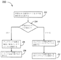
図2は、ハブの運用モードを構成する方法200を示すフロー図である。図2の以下の説明では、方法は、本明細書では図1のDAS100に関連して実装されているとして説明されている。さらに具体的には、方法200は、本明細書では、メイン・ハブ102を使用して実装されているとして説明される。この方法200が、TDDを利用する他の種類の通信システムでも実装できることが理解されるべきである。さらに、方法200は、本明細書では、図1のDAS100によってサポートされる周波数帯のうちの1つに関しても説明される。ただし、このような処理は、他の周波数帯にも実行されることが理解されるべきである。
FIG. 2 is a flow diagram illustrating a
方法200は、所望される運用モードを示す制御信号を生成することを含む(ブロック202)。特に、この制御信号は、単信モードまたは複信モードのどちらかを示す。この例では、制御信号は、メイン・ハブ102のインストール中のユーザ入力に基づいて生成される。ただし、他の実施形態では、制御信号が他の状況で生成し得ることが理解されるべきである。たとえば、いくつかの実施形態では、メイン・ハブ202は、単信インタフェース117への接続の検出に基づいて自己構成するために、自動的に制御信号を生成するように構成される。さらに、RF帯AおよびBのそれぞれに別の制御信号が生成され、同時単信運用および複信運用を可能にする。
The
所望される運用モードは、RF帯AおよびBのそれぞれについて複信または単信のどちらかであると示される(ブロック204)。RF帯AおよびBのうちの1つの所望される運用モードが複信モードであると示されると、それぞれのアップリンクIF/RF回路は、それぞれの単信/複信インタフェース116に接続される(ブロック206)。特に、本実施形態では、以下に詳しく説明するように、アップリンクIF/RF回路は、別のスイッチおよび帯域通過フィルタを介してそれぞれの単信/複信インタフェースに接続される。アップリンクIF/RF回路は、以下に詳しく説明するように、それぞれのRF周波数帯にアップリンクIF信号をアップコンバートするように構成される。複信モードの場合、メイン・ハブ102は、ダウンリンク方向での通信とアップリンク方向での通信の間で切り替わる(ブロック208)。この例示的な実施形態では、ダウンリンク方向の通信とアップリンク方向の通信の間の切り替えは、ダウンリンク方向で伝搬する通信信号について監視することを含む。ダウンリンク信号が検出されると、複信/単信インタフェースが、それぞれのダウンリンクIF/RF回路に切り替えられ、ダウンリンク方向で伝搬するダウンリンク信号が検出されないと、複信/単信インタフェースはそれぞれのアップリンクIF/RF回路に切り替えられる。
The desired mode of operation is indicated as either duplex or simplex for each of RF bands A and B (block 204). When the desired operational mode of one of RF bands A and B is indicated to be duplex mode, each uplink IF / RF circuit is connected to a respective simplex / duplex interface 116 ( Block 206). In particular, in this embodiment, as will be described in detail below, the uplink IF / RF circuit is connected to each simplex / duplex interface via another switch and a bandpass filter. The uplink IF / RF circuit is configured to upconvert the uplink IF signal to the respective RF frequency band, as will be described in detail below. If in duplex mode, the
RF帯AおよびBのうちの1つの所望される運用が単信モードであると示されると、それぞれのアップリンクIF/RF回路は、単信アップリンク・インタフェース117に接続される(ブロック210)。それぞれのダウンリンクIF/RF回路は、それぞれの複信/単信インタフェース116に接続される(ブロック212)。各アップリンクIF/RF回路およびダウンリンクIF/RF回路のそれぞれは、以下に詳しく説明するように、本実施形態では帯域通過フィルタを介してそれぞれのインタフェースに接続される。したがって、この状況では、アップリンクRF信号はインタフェース116に提供されないので、複信/単信インタフェース116は、ダウンリンク通信には単信モードで動作する。方法400は、このようにして、単一のハブが単信運用モードと複信運用モードの両方をサポートできるようにする。両方の運用モードをサポートすると、コンバイナの必要性および各運用モードに対する別個のハブの必要性を排除することによって費用が削減される。 When the desired operation of one of RF bands A and B is indicated to be in simplex mode, each uplink IF / RF circuit is connected to simplex uplink interface 117 (block 210). . Each downlink IF / RF circuit is connected to a respective duplex / simplex interface 116 (block 212). Each of the uplink IF / RF circuit and the downlink IF / RF circuit is connected to each interface via a band pass filter in the present embodiment, as will be described in detail below. Thus, in this situation, no uplink RF signal is provided to interface 116, so duplex / simple interface 116 operates in simplex mode for downlink communications. The method 400 thus enables a single hub to support both simplex and duplex operation modes. Supporting both modes of operation reduces costs by eliminating the need for combiners and the need for a separate hub for each mode of operation.
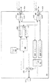
図3は、図1に図示するDASで使用するのに適したメイン・ハブ102の1つの例示的な実施形態のブロック図である。前述したように、メイン・ハブは、TDD WiMAX RF信号を分散するために実装される。ハブ102は、1つが各周波数帯用である2つの帯域通過フィルタ322、および1つが各周波数帯用である2つの帯域通過フィルタ323を含む。帯域通過フィルタ322は、図3で、個々に322Aおよび322Bと呼ばれる。各帯域通過フィルタ322は、メイン・ハブ102の複信/単信RFインタフェース116のそれぞれ1つに接続される。帯域通過フィルタ323は、図3で、個々に323Aおよび323Bと呼ばれる。各帯域通過フィルタ323は、単信アップリンクインタフェース117のそれぞれ1つに接続される。帯域通過フィルタ322は、各RFインタフェース116で受信されるダウンリンクRF信号の中に、および各RFインタフェース116上で出力されるアップリンクRF信号の中に含まれる任意の帯域外信号(すなわち、各周波数帯AまたはBの外部にある任意の信号)を取り除く。帯域通過フィルタ323は、各RFインタフェース117上で出力されるアップリンクRF信号に含まれる任意の帯域外信号を取り除く。
FIG. 3 is a block diagram of one exemplary embodiment of a
メイン・ハブ102は、周波数帯AおよびBのそれぞれに各ダウンリンクIF/RF回路330およびアップリンクIF/RF回路332を含む。ダウンリンクIF/RF回路330は、図3で個々に330Aおよび330Bと呼ばれ、アップリンクIF/RF回路332は、図3で個々に332Aおよび332Bと呼ばれている。周波数帯AおよびBのそれぞれに各スイッチ326が使用され、複信モードでの運用時、その周波数帯の各TDD制御信号の制御下で、各帯域通過フィルタ322を、各ダウンリンクIF/RF回路330または各アップリンクIF/RF回路332のどちらかに選択的に接続する。スイッチ326は、図3で個々に326Aおよび326Bと呼ばれている。
同様に、周波数帯AおよびBのそれぞれに各スイッチ327が使用され、単信モードでの運用時、各アップリンクIF/RF回路332を、その周波数帯の各スイッチ326または各帯域通過フィルタ323のどちらかに選択的に接続する。スイッチ327は、図3で個々に327Aおよび327Bと呼ばれている。さらに、単信モードでの運用時、スイッチ326は、各ダウンリンクIF/RF回路330を各帯域通過フィルタ322に接続するためだけに設定される。 Similarly, each switch 327 is used for each of frequency bands A and B, and when operating in simplex mode, each uplink IF / RF circuit 332 is connected to each switch 326 or each bandpass filter 323 of that frequency band. Selectively connect to either. The switches 327 are individually referred to as 327A and 327B in FIG. Further, when operating in simplex mode, the switch 326 is set only to connect each downlink IF / RF circuit 330 to each bandpass filter 322.
各ダウンリンクIF/RF回路330は、それぞれのRF信号をそれぞれのIF周波数バンドにダウンコンバートする。上で述べたように、本明細書で説明するTDD WiMAX実施形態では、周波数帯AおよびBのダウンリンクRF信号の両方とも同じRF周波数帯を有し、ダウンリンクIF/RF回路330は、周波数帯AおよびBのRF信号を異なるIF帯にダウンコンバートする。1つの実装形態では、各ダウンリンクIF/RF回路330はミクサを含み、このミクサは、生成される適切なIF基準信号を使用して、たとえば、ダウンリンクIF/RF回路330およびアップリンクIF/RF回路332によって使用されるグローバル基準信号(CLOCK)およびRAU106のそれぞれの対応する回路から、各RF信号をダウンコンバートする。このような実装形態では、次いで、ミクサのダウンコンバートされた出力が調整される(たとえば、ダウンコンバートした信号の利得を調整するために増幅され、かつ/または減衰され、任意の帯域外信号を排除するために帯域通過フィルタリングされる)。
Each downlink IF / RF circuit 330 downconverts the respective RF signal to the respective IF frequency band. As noted above, in the TDD WiMAX embodiments described herein, both downlink RF signals in frequency bands A and B have the same RF frequency band, and the downlink IF / RF circuit 330 Down-convert the RF signals of bands A and B to different IF bands. In one implementation, each downlink IF / RF circuit 330 includes a mixer, which uses the appropriate IF reference signal that is generated, for example, the downlink IF / RF circuit 330 and the uplink IF / Each RF signal is down-converted from the corresponding circuit of the global reference signal (CLOCK) and
マルチプレクサ340は、ダウンリンクIF/RF回路330によって出力されるダウンリンクIF信号、グローバル基準信号(CLOCK)、運用、管理および保守(OAM)チャネル(FSK)、ならびにダウンリンク・パイロット信号(PILOT)を結合する。OAMチャネルは、メイン・ハブ102と遠隔アンテナ装置106のそれぞれの間で運用、管理および保守情報を通信するために使用される。図3に示す特定の実施形態では、このようなOAM情報は、周波数シフトキーイング(FSK)変調/復調を使用して、OAMチャネルで変調され、OAMチャネルから復調される。ダウンリンク・パイロット信号は、遠隔アンテナ装置106でダウンリンク自動利得制御を実行するために使用される。ダウンリンクIF信号、グローバル基準信号(CLOCK)、運用チャネル(FSK)、およびダウンリンク・パイロット信号(PILOT)は、周波数分割多重化(FDM)を使用して結合される。マルチプレクサ340の電気出力は、(図3にE/Oインタフェース342として示す)アナログ光変調器を使用して)光搬送波を変調するために使用される。結果として得られるダウンリンク光信号は、次いで分割され、各拡張ハブ104に提供される。
また、メイン・ハブ102は、メイン・ハブ102が接続される各拡張ハブ104のためのO/Eインタフェース344を含む。各O/Eインタフェース344は、それぞれの拡張ハブ104から送信されるそれぞれのアップリンク光信号を復調する。結果として得られる電気アップリンク信号は、次いで、周波数に基づきデマルチプレクサ341によって非多重化され、周波数帯AのアップリンクIF信号を、周波数帯BのアップリンクIF信号から分離し、(アップリンクIF信号の自動利得制御に使用される)アップリンク・パイロット信号および(処理のために(以下に説明する)コントローラ324に提供される)OAM信号を抽出する。各周波数帯のアップリンクIF信号は、それぞれのアップリンクIF/RF回路332に供給される。
The
各アップリンクIF/RF回路332は、それぞれのアップリンクIF信号をそれぞれのRF周波数帯にアップコンバートする。上で述べたように、本明細書で説明するTDD WiMAX実施形態では、周波数帯AおよびBのアップリンクRF信号の両方とも同じRF周波数帯を有し、各アップリンクIF/RF回路332は、(異なる周波数帯を有する)周波数帯AおよびBのIF信号を同じRF帯にアップコンバートする。1つの実装形態では、各アップリンクIF/RF回路332はミクサを含み、このミクサは、生成される適切なRF基準信号を使用して、たとえばグローバル基準信号(CLOCK)からそれぞれのIF信号をアップコンバートする。このような実装形態では、ミクサのアップコンバートされた出力は、次いで調整される(たとえば、アップリンク・パイロット信号を使用してアップコンバートした信号の利得を調整するために増幅され、かつ/または減衰され、あらゆる帯域外信号を排除するために帯域通過フィルタリングされる)。 Each uplink IF / RF circuit 332 upconverts the respective uplink IF signal to the respective RF frequency band. As noted above, in the TDD WiMAX embodiment described herein, both uplink RF signals in frequency bands A and B have the same RF frequency band, and each uplink IF / RF circuit 332 includes: Up-convert IF signals in frequency bands A and B (with different frequency bands) to the same RF band. In one implementation, each uplink IF / RF circuit 332 includes a mixer that uses the appropriate generated RF reference signal to up the respective IF signal, eg, from a global reference signal (CLOCK). Convert. In such implementations, the mixer's upconverted output is then adjusted (eg, amplified and / or attenuated to adjust the gain of the upconverted signal using an uplink pilot signal). And bandpass filtered to eliminate any out-of-band signals).
メイン・ハブ102は、DAS100の動作を制御するコントローラ324を含む。コントローラ324は、両方の周波数帯AおよびBのためのスイッチ322および323の切り替えを制御するために信号を生成する。複信動作のためにメイン・ハブ102を構成すると、コントローラ324は、それぞれのスイッチ327がそれぞれのアップリンクIF/RF回路332をそれぞれのスイッチ326に接続しなければならないことを示すスイッチ制御信号をアサートする。次に、複信モードで動作中に、コントローラ324は、それそれの検出器回路320によって生成される検出信号に基づいて、それぞれのスイッチ326にスイッチ制御信号を生成する。検出器回路320のそれぞれは、図3で個々に320Aおよび320Bと呼ばれている。各検出器回路320は、それぞれの帯域通過フィルタ322に接続される。各検出器回路320は、ダウンリンク方向で伝搬する通信ダウンリンクRF信号について監視する。各検出器回路320がダウンリンクRF信号を検出すると、検出器回路320は、その事実をコントローラ324に示すためにその検出信号をアサートする。各検出器回路320は、既定の方向で通信されている信号を検出するように構成された任意の適切な検出器回路を使用して実装できる。例示的な検出器回路を、図4にさらに詳しく図示し、説明する。
The
検出器回路320の1つがその検出信号をアサートすると、コントローラ324は対応する周波数帯のそれぞれのスイッチ制御信号をアサートする。たとえば、検出器回路320Aが周波数帯AのためのダウンリンクRF信号を検出する場合、コントローラ324は周波数帯Aのためのその制御信号をアサートする。各スイッチ326は、スイッチ制御信号がアサートされると、それぞれのダウンリンクIF/RF回路330をそれぞれのRFインタフェース116に接続し、それぞれのスイッチ制御信号がアサートされないと、それぞれのアップリンクIF/RF回路332をそれぞれのRFインタフェース116に接続するように構成される。このような切り替えにより、それぞれのダウンリンクIF/RF回路330が、ダウンリンク方向で通信されている任意のダウンリンクRF信号をダウンコンバートし、調整でき、それぞれのアップリンクIF/RF回路332が、アップリンク方向で通信されている任意のアップリンクIF信号をアップコンバートし、調整できる。
When one of the
単信モードにハブ102を構成すると、コントローラ324は、それぞれのスイッチ326および327のスイッチ制御信号を生成し、アサートする。具体的には、コントローラ324は、それぞれのスイッチ326が、それぞれのダウンリンクIF/RF回路330を、各周波数帯のそれぞれの帯域通過フィルタ322に接続しなければならないことを示すスイッチ制御信号をアサートする。また、コントローラ324は、それぞれのアップリンクIF/RF回路332を、それぞれの帯域通過フィルタ323に接続しなければならないことを示す制御信号もアサートする。単信モード運用中、コントローラ324は、追加のスイッチ制御信号をアサートしない。
When the
図4は、メイン・ハブ102で使用される例示的な検出器回路320のブロック図である。図4に図示するように、検出器回路322は、ダウンリンク方向で伝搬する信号を不均一に分割し、アップリンク方向で伝搬する信号を完全に通過させるように構成される方向性結合器462を含む。このようにして、ダウンリンク信号の信号振幅の小さな部分が、方向性結合器462を通って増幅器464に渡される。増幅器464は、所定の利得分、この分割信号を増幅する。増幅された信号は、次いで検出器466に渡される。検出器466は、閾値振幅レベルを超えない限り、増幅信号がコントローラ324に渡されるのを禁止する。したがって、検出器466は、雑音がダウンリンク信号として間違って解釈されるのを防ぐ。いったん閾値振幅レベルを超えると、増幅信号はコントローラに渡される。検出器466は、逆バイアスダイオード、二乗平均平方根(RMS)検出器、およびアナログデバイスIC、パーツ番号AD8362等の集積回路検出器を含むが、これらに限定されるものではない多様な回路構成要素を使用して実装できる。さらに、検出器回路322は、図4に示す例示的な検出器回路に制限されない。たとえば、いくつかの実施形態では、第921号出願または第916号出願に説明される検出器回路が使用される。
FIG. 4 is a block diagram of an
図5は、メイン・ハブ102との間で通信される信号の周波数マップである。とりわけ、図5に示し、本明細書で議論する周波数は、制限するためにではなく、一例として提供されている。他の実施形態では他の周波数を使用し得ることが理解されるべきである。IFバンドのそれぞれは、アップリンクIF信号を通信するための部分(つまり、サブバンド)およびダウンリンクIF信号を通信するための部分を含む。周波数マップは、(図5に示す例では10.7MHzで)グローバル基準信号(CLOCK)を含む。また、周波数はRF帯AおよびBのそれぞれに対応するIF周波数帯も含む。いくつかの実施形態では、周波数帯AおよびBは、幅が30MHzまたは66MHzのどちらかとなるように選択できる。運用中のRF周波数帯および対応するIF周波数帯は、インストール中に現場で構成される。たとえば、以下の表1は、30MHz帯または66MHz帯として構成されたときの周波数帯AおよびBの例示的なアップリンクIF周波数帯およびダウンリンクIF周波数帯を表示する。
FIG. 5 is a frequency map of signals communicated with the

また、周波数マップは、(図5に図示する例では、それぞれ609.9MHzおよび315MHzで)ダウンリンク・パイロット信号およびアップリンク・パイロット信号(PILOT)を含む。この例のアップリンク・パイロット信号は、メイン・ハブ102と拡張ハブ104の間で、315MHzで設定されている。さらに、この例のアップリンク・パイロット信号は、拡張ハブ104とRAU106の間で、140MHzで設定されている。また、周波数マップは、(図5に図示する例では、900MHzで)OAMチャネル(FSK)を含む。
The frequency map also includes a downlink pilot signal and an uplink pilot signal (PILOT) (in the example illustrated in FIG. 5 at 609.9 MHz and 315 MHz, respectively). The uplink pilot signal in this example is set at 315 MHz between the
図6は、図1のDAS100で使用するために適した遠隔アンテナ装置106の一実施形態のブロック図である。RAU106は、トランスポート・インタフェース646を介してそれぞれの拡張ハブ104に通信可能に接続される。ダイプレクサ648は、トランスポート・インタフェース646上でアップリンクIF信号およびアップリンク・パイロット信号を出力し、ダウンリンクIF信号、グローバル基準信号、ダウンリンク・パイロット信号、およびOAM信号を受信するために使用される。ダウンリンク信号は、フィルタ650によって分離される。パイロット信号は、最終的にはRAU106から発せられるダウンリンクRF信号の利得を制御する際に使用するためにパイロット検出器652に渡される。
FIG. 6 is a block diagram of one embodiment of a
RAU106は、(個々に656Aおよび656Bと呼ばれている)周波数帯AおよびBのそれぞれのためのダウンリンクIF/RF回路656、および(個々に658Aおよび658Bと呼ばれている)周波数帯AおよびBのそれぞれのためのアップリンクIF/RF回路658を含む。
The
各ダウンリンクIF/RF回路656は、それぞれのダウンリンクIF信号をそれぞれのRF周波数バンドにアップコンバートする。上で述べたように、本明細書で説明するTDD WiMAX実施形態では、周波数帯AおよびBのダウンリンクRF信号の両方とも、同じRF周波数帯を有する。ダウンリンクIF/RF回路656は、(異なるIF周波数帯を有する)周波数帯AおよびBのIF信号を同じRF帯にアップコンバートする。1つの実装形態では、各ダウンリンクIF/RF回路656はミクサを含み、このミクサは、生成される適切なRF基準信号を使用し、たとえばRAU106で受信されるグローバル基準信号(CLOCK)から、それぞれのIF信号をアップコンバートする。このような実装形態では、ミクサのアップコンバートされた出力が次いで調整される(たとえば、ダウンリンク・パイロット信号を使用してアップコンバートした信号の利得を調整するために増幅され、かつ/または減衰され、任意の帯域外信号を排除するために帯域通過フィルタリングされる)。アップコンバートされたRF信号は、次いでそこから(以下に説明するように、それぞれのスイッチ760がダウンリンクIF/RF回路656をアンテナ118に接続するときに――それぞれのスイッチ760およびそれぞれの帯域通過フィルタ762を介して)発するためにアンテナ118の各アンテナに供給される。アンテナ118のそれぞれは、それぞれの無線周波数インタフェース661を介して遠隔アンテナ装置106(およびその構成要素)に接続される。
Each downlink IF / RF circuit 656 upconverts the respective downlink IF signal to the respective RF frequency band. As noted above, in the TDD WiMAX embodiments described herein, both downlink RF signals in frequency bands A and B have the same RF frequency band. Downlink IF / RF circuit 656 upconverts IF signals in frequency bands A and B (having different IF frequency bands) to the same RF band. In one implementation, each downlink IF / RF circuit 656 includes a mixer that uses the appropriate generated RF reference signal, eg, from a global reference signal (CLOCK) received at the
アンテナ118のそれぞれから受信されるアップリンクRF信号は、(以下に説明するように、それぞれのスイッチ660がアンテナ118をアップリンクIF/RF回路658に接続するときに――それぞれの帯域通過フィルタ662およびそれぞれのスイッチ660を介して)それぞれのアップリンクIF/RF回路658に提供される。各アップリンクIF/RF回路658は、それぞれのアップリンクRF信号をそれぞれのIF周波数帯にダウンコンバートする。上で述べたように、本明細書で説明するTDD WiMAX実施形態では、周波数帯AおよびBのアップリンクRF信号の両方とも同じアップリンクRF周波数帯を有し、アップリンクIF/RF回路658は、周波数帯AおよびBのアップリンクRF信号を異なるIF帯にダウンコンバートする。1つの実装形態では、各アップリンクIF/RF回路658はミクサを含み、このミクサは、生成される適切なIF基準信号を使用し、たとえばRAU106で受信されるグローバル基準信号(CLOCK)からそれぞれのアップリンクRF信号をダウンコンバートする。このような実装形態では、ミクサのダウンコンバートされた出力が次いで調整される(たとえば、ダウンコンバートした信号の利得を調整するために増幅され、かつ/および減衰され、任意の帯域外信号を排除するために帯域通過フィルタリングされる)。
The uplink RF signal received from each of the antennas 118 (when each switch 660 connects the antenna 118 to the uplink IF / RF circuit 658—as described below—the respective bandpass filter 662 And via each switch 660) to each uplink IF / RF circuit 658. Each uplink IF / RF circuit 658 downconverts the respective uplink RF signal to the respective IF frequency band. As noted above, in the TDD WiMAX embodiment described herein, both uplink RF signals in frequency bands A and B have the same uplink RF frequency band, and the uplink IF / RF circuit 658 is Downconvert the uplink RF signals of frequency bands A and B to different IF bands. In one implementation, each uplink IF / RF circuit 658 includes a mixer that uses an appropriate IF reference signal that is generated, eg, from a global reference signal (CLOCK) received at the
コンバイナ664は、アップリンクIF/RF回路658によって出力されるアップリンクIF信号およびアップリンク・パイロット信号を結合する。アップリンク・パイロット信号は、メイン・ハブ102でアップリンク自動利得制御を行うために使用される。アップリンクIF信号およびアップリンク・パイロット信号は、周波数分割多重化を使用して結合される。コンバイナ664の出力は、ダイプレクサ648を介してトランスポート・インタフェース646上で出力される。
図1から図6に図示する実施形態は、メイン・ハブ102を遠隔アンテナ装置106に接続するために1つまたは複数の拡張ハブ104を使用するとして説明しているが、別の例では、メイン・ハブ102は、拡張ハブを使わずに直接的に遠隔アンテナ装置106に接続される。このような1つの実施形態では、このメイン・ハブは、このメイン・ハブがスプリッタを含み、そのスプリッタがマルチプレクサ340によって出力されるダウンリンクIF信号を、メイン・ハブが接続される各遠隔アンテナ装置のダウンリンクIF信号の別のインスタンスの中に分割するという点を除き、図1および図3に図示するメイン・ハブ102に類似している。このような実装形態のメイン・ハブは、メイン・ハブが接続される遠隔アンテナ装置ごとに別個のダイプレクサも含み、この場合、ダイプレクサはダウンリンクIF信号のインスタンスを、そのダイプレクサに関連付けられた遠隔アンテナ装置によって出力されるアップリンクIF信号と結合する。また、このような実装形態のメイン・ハブはコンバイナも含み、このコンバイナは遠隔アンテナ装置から受信されるアップリンクIF信号のすべてを結合し、デマルチプレクサ341に供給される結合アップリンクIF信号を出力する。いくつかの実施形態では、遠隔アンテナ装置のいくつかは、拡張ハブを介してメイン・ハブに接続され、遠隔アンテナ装置のいくつかは、拡張ハブを使わずにメイン・ハブに直接的に接続される。
Although the embodiment illustrated in FIGS. 1-6 is described as using one or
図1から図6に図示する実施形態は、2つの周波数帯をトランスポートするために実装されるとして説明されるが、他の実施形態では、異なる数の周波数帯がトランスポートされる。たとえば、このような1つの実施形態では、DASは、(たとえば、非シールド・ツイストペアケーブル等の相対的に低帯域幅のケーブルを使用して)単一の周波数帯を分散するために使用される。別の実施形態では、3つまたは4つ以上の周波数帯がトランスポートされる。 While the embodiment illustrated in FIGS. 1-6 is described as being implemented to transport two frequency bands, in other embodiments, a different number of frequency bands are transported. For example, in one such embodiment, DAS is used to distribute a single frequency band (eg, using a relatively low bandwidth cable such as an unshielded twisted pair cable). . In another embodiment, three or more frequency bands are transported.
図1から図6に図示する実施形態は、2つのMIMO WiMAX周波数帯をトランスポートするために実装されるとして説明されるが、他の実施形態では、他のタイプのTDD信号がトランスポートされる(たとえば、非MIMO WiMAX信号)。 While the embodiment illustrated in FIGS. 1-6 is described as being implemented to transport two MIMO WiMAX frequency bands, in other embodiments, other types of TDD signals are transported. (For example, non-MIMO WiMAX signal).
本明細書に具体的な実施形態を示し、説明したが、同じ目的を達成するために計算される任意の装置が、図示する特定の実施形態に代わり得ることが当業者により理解されるであろう。本出願は、本発明の任意の適応または変化を包含することを目的とする。したがって、本発明が請求項およびその均等物によってのみ制限されることが明白に意図される。 While specific embodiments have been shown and described herein, it will be understood by those skilled in the art that any device calculated to accomplish the same purpose can be substituted for the specific embodiments illustrated. Let's go. This application is intended to cover any adaptations or variations of the present invention. Therefore, it is manifestly intended that this invention be limited only by the claims and the equivalents thereof.
Claims (13)
前記第1の装置に通信可能に接続される第2の装置と、
を備え、
前記第1の装置が、上流装置から第1のインタフェースを介して第1のオリジナルの無線周波数信号を受信するように作動し、前記第2の装置が下流装置から第2のインタフェースを介して第2のオリジナルの無線周波数信号を受信するように作動し、
前記第2の装置が、前記第2のインタフェースを介して前記下流装置に第1の再生無線周波数信号を出力するように作動し、前記第1の再生無線周波数信号の内容が、前記第1のオリジナルの無線周波数信号から導出され、
前記第1の装置が、前記第1のインタフェースおよび第3のインタフェースのうちの1つを介して前記上流装置に第2の再生無線周波数信号を出力するように作動し、前記第2の再生無線周波数信号の内容が、前記第2のオリジナルの無線周波数信号から導出され、
前記第1のインタフェースが、前記第2の再生無線周波数信号が前記第3のインタフェースを介して出力されるときに、単信インタフェースとして動作可能であり、前記第2の再生無線周波数信号が前記第1のインタフェースを介して出力されるときに、複信インタフェースとして動作可能である、
通信システム。 A first device;
A second device communicatively connected to the first device;
With
The first device is operable to receive a first original radio frequency signal from an upstream device via a first interface, and the second device is configured to receive a first original radio frequency signal from a downstream device via a second interface. Operates to receive two original radio frequency signals,
The second device is operative to output a first regenerated radio frequency signal to the downstream device via the second interface, wherein the content of the first regenerated radio frequency signal is Derived from the original radio frequency signal,
The first device is operative to output a second regenerative radio frequency signal to the upstream device via one of the first interface and a third interface, the second regenerative radio; The content of the frequency signal is derived from the second original radio frequency signal;
The first interface is operable as a simplex interface when the second reproduced radio frequency signal is output via the third interface, and the second reproduced radio frequency signal is the first reproduced radio frequency signal. It can operate as a duplex interface when it is output through one interface.
Communications system.
前記第1のインタフェースを介して受信される無線周波数信号を処理するように構成されたダウンリンク回路と、
前記第1のインタフェースおよび前記第3のインタフェースのうちの1つを介して出力するために信号を処理するように構成されたアップリンク回路と、
前記アップリンク回路および前記ダウンリンク回路のうちの1つに前記第1のインタフェースを接続するように構成された第1のスイッチと、
前記第1のスイッチおよび前記第3のインタフェースのうちの1つに前記アップリンク回路を接続するように構成された第2のスイッチと、
前記第1のスイッチおよび前記第2のスイッチの切り替えを制御するように構成されたスイッチ・コントローラと、
を含み、
前記第1のスイッチは、前記第2のスイッチが前記アップリンク回路を前記第3のインタフェースに接続するとき、前記第1のインタフェースを前記ダウンリンク回路のみに接続するように構成され、
前記第1のスイッチは、前記第2のスイッチが前記アップリンク回路を前記第1のスイッチに接続するとき、前記第1のインタフェースを前記ダウンリンク回路又は前記アップリンク回路に接続するように構成された、
請求項1に記載の通信システム。 The first device comprises:
A downlink circuit configured to process a radio frequency signal received via the first interface;
An uplink circuit configured to process a signal for output via one of the first interface and the third interface;
A first switch configured to connect the first interface to one of the uplink circuit and the downlink circuit;
A second switch configured to connect the uplink circuit to one of the first switch and the third interface;
A switch controller configured to control switching of the first switch and the second switch;
Including
The first switch is configured to connect the first interface only to the downlink circuit when the second switch connects the uplink circuit to the third interface;
The first switch is configured to connect the first interface to the downlink circuit or the uplink circuit when the second switch connects the uplink circuit to the first switch. The
The communication system according to claim 1.
前記第1のインタフェースを介して受信される無線周波数信号について監視するように構成された検出器回路
を含み、
無線周波数信号が前記第1のインタフェースを介して受信されると、前記検出器回路が前記スイッチ・コントローラに、前記第1のインタフェースが前記ダウンリンク回路に接続されるように前記第1のスイッチが切り替えられなければならないことを示す信号を渡す、
請求項2に記載の通信システム。 The first device further comprises:
A detector circuit configured to monitor for radio frequency signals received via the first interface;
When a radio frequency signal is received via the first interface, the first switch is connected such that the detector circuit is connected to the switch controller and the first interface is connected to the downlink circuit. Pass a signal indicating that it must be switched,
The communication system according to claim 2.
前記第1のインタフェースで受信された無線周波信号の部分を分離するように構成された方向性結合器と、
前記方向性結合器に接続され、伝搬する前記無線周波数信号の前記分離部分を増幅するように構成された増幅器と、
前記分離部分の振幅が閾値振幅レベルを超えない限り、前記増幅された分離部分の伝搬を遮るように構成された検出器と、
を含む、請求項3に記載の通信システム。 The detector circuit comprises:
A directional coupler configured to separate a portion of a radio frequency signal received at the first interface;
An amplifier connected to the directional coupler and configured to amplify the separated portion of the propagating radio frequency signal;
A detector configured to block propagation of the amplified separation portion as long as the amplitude of the separation portion does not exceed a threshold amplitude level;
The communication system according to claim 3, comprising:
前記第1のインタフェースに接続され、所望される周波数帯を選択するように構成された第1の帯域通過フィルタと、
前記第3のインタフェースに接続され、所望される周波数帯を選択するように構成された第2の帯域通過フィルタと、
を含む、請求項2に記載の通信システム。 A first bandpass filter connected to the first interface and configured to select a desired frequency band; and
A second bandpass filter connected to the third interface and configured to select a desired frequency band;
The communication system according to claim 2, comprising:
再生無線周波数信号を前記上流装置に送信するように作動する第2のインタフェースと、
前記オリジナル無線周波数信号を、前記オリジナル無線周波数信号を再生し、下流装置に出力するように作動する第2の装置にトランスポートするためのトランスポート信号を生成するように作動する第1の回路と、
前記第1のインタフェースおよび前記第2のインタフェースのうちの1つを介して前記上流装置に伝送するために、前記第2の装置から受信される信号に基づく前記再生無線周波数信号を生成するように作動する第2の回路と、
前記第1のインタフェースを、前記第1の回路および前記第2の回路のうちの1つに接続するように作動する第1のスイッチと、
前記第2の回路を、前記第1のスイッチおよび前記第2のインタフェースのうちの1つに接続するように作動する第2のスイッチと、
前記第1のスイッチおよび前記第2のスイッチの切り替えを制御するように作動するスイッチ・コントローラと、
を備え、
前記第1のスイッチは、前記第2のスイッチが前記第2の回路を前記第2のインタフェースに接続するとき、前記第1のインタフェースを前記第1の回路のみに接続するように構成され、
前記第1のスイッチは、前記第2のスイッチが前記第2の回路を前記第1のスイッチに接続するとき、前記第1のインタフェースを前記第1の回路又は前記第2の回路に接続するように構成された、
通信装置。 A first interface operable to receive an original radio frequency signal from an upstream device, wherein the first interface is further operable to transmit a regenerative radio frequency signal to the upstream device;
A second interface operable to transmit a regenerated radio frequency signal to the upstream device;
A first circuit operable to generate a transport signal for transporting the original radio frequency signal to a second device operable to reproduce and output the original radio frequency signal to a downstream device; ,
Generating the regenerated radio frequency signal based on a signal received from the second device for transmission to the upstream device via one of the first interface and the second interface. A second circuit to operate;
A first switch operative to connect the first interface to one of the first circuit and the second circuit;
A second switch operative to connect the second circuit to one of the first switch and the second interface;
A switch controller that operates to control switching of the first switch and the second switch;
With
The first switch is configured to connect the first interface only to the first circuit when the second switch connects the second circuit to the second interface;
The first switch connects the first interface to the first circuit or the second circuit when the second switch connects the second circuit to the first switch. Configured
Communication device.
前記第1のインタフェースを介して受信される無線周波数信号について監視するように構成された検出器回路
を含み、
無線周波数信号が、前記第1のインタフェースを介して受信されるときに、前記検出器回路が前記スイッチ・コントローラに、前記第1のインタフェースが前記ダウンリンク回路に接続されるように前記第1のスイッチが切り替えられなければならないことを示す信号を渡す、
請求項6に記載の通信装置。 The communication device further comprises:
A detector circuit configured to monitor for radio frequency signals received via the first interface;
When a radio frequency signal is received via the first interface, the first circuit is connected to the switch controller and the first interface is connected to the downlink circuit. Pass a signal indicating that the switch must be switched,
The communication apparatus according to claim 6.
前記第1のインタフェースで受信される無線周波数信号の部分を分離するように構成された方向性結合器と、
方向性結合器に接続され、伝搬する前記無線周波数の前記分離部分を増幅するように構成された増幅器と、
前記分離部分の前記振幅が、閾値振幅レベルを超えない限り、前記増幅された分離部分の伝搬を遮るように構成された検出器と、
を含む、請求項7に記載の通信装置。 The detector circuit comprises:
A directional coupler configured to separate a portion of a radio frequency signal received at the first interface;
An amplifier connected to a directional coupler and configured to amplify the separated portion of the propagating radio frequency;
A detector configured to block propagation of the amplified separation portion as long as the amplitude of the separation portion does not exceed a threshold amplitude level;
The communication device according to claim 7, comprising:
前記第1のインタフェースに接続され、所望される周波数帯を選択するように構成された第1の帯域通過フィルタと、
前記第2のインタフェースに接続され、所望される周波数帯を選択するように構成された第2の帯域通過フィルタと、
を含む、請求項7に記載の通信装置。 The communication device further comprises:
A first bandpass filter connected to the first interface and configured to select a desired frequency band;
A second bandpass filter connected to the second interface and configured to select a desired frequency band;
The communication device according to claim 7, comprising:
前記所望される運用モードを示す制御信号を生成することと、
前記制御信号が、前記所望される運用モードが複信モードであることを示すと、
オリジナル無線周波数信号を第2の装置にトランスポートするためのトランスポート信号を生成するように作動する第1の回路と、再生無線周波数信号を生成するように作動する第2の回路の間で第1のスイッチを切り替え、前記第1の回路および前記第2の回路を第1のインタフェースに接続することと、
第2のスイッチを切り替えて、前記第2の回路を前記第1のスイッチに接続することと、
前記制御信号が、前記所望される運用モードが単信モードであることを示すと、
前記第1のスイッチを切り替え、前記第1の回路を前記第1のインタフェースに接続することと、
前記第2のスイッチを切り替え、前記第2の回路を第2のインタフェースに接続することと、
を含む方法。 A method for configuring an operation mode of a communication device , comprising:
Generating a control signal indicative of the desired operational mode;
When the control signal indicates that the desired operating mode is duplex mode,
A first circuit that operates to generate a transport signal for transporting an original radio frequency signal to a second device and a second circuit that operates to generate a regenerative radio frequency signal. Switching one switch and connecting the first circuit and the second circuit to a first interface;
Switching a second switch to connect the second circuit to the first switch;
When the control signal indicates that the desired operating mode is simplex mode,
Switching the first switch and connecting the first circuit to the first interface;
Switching the second switch and connecting the second circuit to a second interface;
Including methods.
前記第1のインタフェースを介して受信される前記オリジナル無線周波数信号について監視することと、
オリジナル無線周波数信号が検出されると、前記第1のスイッチを切り替え、前記第1の回路を前記第1のインタフェースに接続することと、
オリジナル無線周波数信号が検出されないと、前記第1のスイッチを切り替え、前記第2の回路を前記第1のインタフェースに接続することと、
を含む、請求項10に記載の方法。 Switching the first switch between the first circuit and the second circuit;
Monitoring for the original radio frequency signal received via the first interface;
When an original radio frequency signal is detected, switching the first switch and connecting the first circuit to the first interface;
If the original radio frequency signal is not detected, switching the first switch and connecting the second circuit to the first interface;
The method of claim 10, comprising:
前記オリジナル無線周波数信号の部分を分離することと、
前記オリジナル無線周波数信号の前記分離部分を増幅することと、
前記分離部分の前記振幅が閾値レベルを超える場合、前記オリジナル無線周波数信号の前記増幅した分離部分をスイッチ・コントローラに渡すことと、
を含む、請求項11に記載の方法。 Monitoring the original radio frequency signal;
Separating a portion of the original radio frequency signal;
Amplifying the separated portion of the original radio frequency signal;
Passing the amplified separated portion of the original radio frequency signal to a switch controller if the amplitude of the separated portion exceeds a threshold level;
12. The method of claim 11 comprising:
前記通信装置のインストール中にユーザ入力に基づいて制御信号を生成することと、
を含む、請求項10に記載の方法。 Generating a control signal,
Generating a control signal based on user input during installation of the communication device;
The method of claim 10, comprising:
Applications Claiming Priority (3)
| Application Number | Priority Date | Filing Date | Title |
|---|---|---|---|
| US12/144,913 US8208414B2 (en) | 2008-06-24 | 2008-06-24 | System and method for configurable time-division duplex interface |
| US12/144,913 | 2008-06-24 | ||
| PCT/US2009/048145 WO2010008794A2 (en) | 2008-06-24 | 2009-06-22 | System and method for configurable time-division duplex interface |
Publications (3)
| Publication Number | Publication Date |
|---|---|
| JP2011525753A JP2011525753A (en) | 2011-09-22 |
| JP2011525753A5 JP2011525753A5 (en) | 2012-07-26 |
| JP5406923B2 true JP5406923B2 (en) | 2014-02-05 |
Family
ID=41431197
Family Applications (1)
| Application Number | Title | Priority Date | Filing Date |
|---|---|---|---|
| JP2011514884A Expired - Fee Related JP5406923B2 (en) | 2008-06-24 | 2009-06-22 | System and method for a configurable time division duplex interface |
Country Status (6)
| Country | Link |
|---|---|
| US (1) | US8208414B2 (en) |
| EP (2) | EP2294722B1 (en) |
| JP (1) | JP5406923B2 (en) |
| CN (1) | CN102084606B (en) |
| CA (1) | CA2727770C (en) |
| WO (1) | WO2010008794A2 (en) |
Families Citing this family (96)
| Publication number | Priority date | Publication date | Assignee | Title |
|---|---|---|---|---|
| US8396368B2 (en) | 2009-12-09 | 2013-03-12 | Andrew Llc | Distributed antenna system for MIMO signals |
| IT1403065B1 (en) * | 2010-12-01 | 2013-10-04 | Andrew Wireless Systems Gmbh | DISTRIBUTED ANTENNA SYSTEM FOR MIMO SIGNALS. |
| US8380143B2 (en) | 2002-05-01 | 2013-02-19 | Dali Systems Co. Ltd | Power amplifier time-delay invariant predistortion methods and apparatus |
| US8811917B2 (en) | 2002-05-01 | 2014-08-19 | Dali Systems Co. Ltd. | Digital hybrid mode power amplifier system |
| KR20100014339A (en) | 2006-12-26 | 2010-02-10 | 달리 시스템즈 씨오. 엘티디. | Method and system for baseband predistortion linearization in multi-channel wideband communication systems |
| WO2009053910A2 (en) | 2007-10-22 | 2009-04-30 | Mobileaccess Networks Ltd. | Communication system using low bandwidth wires |
| US8175649B2 (en) | 2008-06-20 | 2012-05-08 | Corning Mobileaccess Ltd | Method and system for real time control of an active antenna over a distributed antenna system |
| US8626238B2 (en) * | 2008-06-24 | 2014-01-07 | Adc Telecommunications, Inc. | Method and apparatus for switching in a TDD system |
| US8310963B2 (en) | 2008-06-24 | 2012-11-13 | Adc Telecommunications, Inc. | System and method for synchronized time-division duplex signal switching |
| US9363469B2 (en) | 2008-07-17 | 2016-06-07 | Ppc Broadband, Inc. | Passive-active terminal adapter and method having automatic return loss control |
| US7961689B2 (en) * | 2008-08-18 | 2011-06-14 | Adc Telecommunications, Inc. | Method and apparatus for determining an end of a subframe in a TDD system |
| US9647851B2 (en) | 2008-10-13 | 2017-05-09 | Ppc Broadband, Inc. | Ingress noise inhibiting network interface device and method for cable television networks |
| US8516537B2 (en) * | 2009-10-09 | 2013-08-20 | Ppc Broadband, Inc. | Downstream bandwidth conditioning device |
| US20110085586A1 (en) * | 2009-10-09 | 2011-04-14 | John Mezzalingua Associates, Inc. | Total bandwidth conditioning device |
| US8832767B2 (en) * | 2008-10-16 | 2014-09-09 | Ppc Broadband, Inc. | Dynamically configurable frequency band selection device between CATV distribution system and CATV user |
| US8385219B2 (en) | 2009-10-09 | 2013-02-26 | John Mezzalingua Associates, Inc. | Upstream bandwidth level measurement device |
| US8213457B2 (en) * | 2009-10-09 | 2012-07-03 | John Mezzalingua Associates, Inc. | Upstream bandwidth conditioning device |
| US8464301B2 (en) * | 2008-10-16 | 2013-06-11 | Ppc Broadband, Inc. | Upstream bandwidth conditioning device between CATV distribution system and CATV user |
| US8510782B2 (en) | 2008-10-21 | 2013-08-13 | Ppc Broadband, Inc. | CATV entry adapter and method for preventing interference with eMTA equipment from MoCA Signals |
| US11910052B2 (en) | 2008-10-21 | 2024-02-20 | Ppc Broadband, Inc. | Entry device for communicating external network signals and in-home network signals |
| AU2010210771B2 (en) * | 2009-02-03 | 2015-09-17 | Corning Cable Systems Llc | Optical fiber-based distributed antenna systems, components, and related methods for calibration thereof |
| WO2010090999A1 (en) | 2009-02-03 | 2010-08-12 | Corning Cable Systems Llc | Optical fiber-based distributed antenna systems, components, and related methods for monitoring and configuring thereof |
| US9673904B2 (en) | 2009-02-03 | 2017-06-06 | Corning Optical Communications LLC | Optical fiber-based distributed antenna systems, components, and related methods for calibration thereof |
| JP5649588B2 (en) | 2009-02-08 | 2015-01-07 | コーニング モバイルアクセス エルティディ. | Communication system using a cable for carrying an Ethernet signal |
| US8346091B2 (en) * | 2009-04-29 | 2013-01-01 | Andrew Llc | Distributed antenna system for wireless network systems |
| US8588614B2 (en) * | 2009-05-22 | 2013-11-19 | Extenet Systems, Inc. | Flexible distributed antenna system |
| PL2484074T3 (en) * | 2009-09-30 | 2014-12-31 | Optis Wireless Technology Llc | Reconfiguration of active component carrier set in multi-carrier wireless systems |
| DE102009052936B8 (en) | 2009-11-12 | 2012-05-10 | Andrew Wireless Systems Gmbh | Master unit, remote unit as well as multiband transmission system |
| US8280259B2 (en) | 2009-11-13 | 2012-10-02 | Corning Cable Systems Llc | Radio-over-fiber (RoF) system for protocol-independent wired and/or wireless communication |
| IT1398025B1 (en) * | 2010-02-12 | 2013-02-07 | Andrew Llc | DISTRIBUTED ANTENNA SYSTEM FOR MIMO COMMUNICATIONS. |
| US8275265B2 (en) | 2010-02-15 | 2012-09-25 | Corning Cable Systems Llc | Dynamic cell bonding (DCB) for radio-over-fiber (RoF)-based networks and communication systems and related methods |
| US8479247B2 (en) | 2010-04-14 | 2013-07-02 | Ppc Broadband, Inc. | Upstream bandwidth conditioning device |
| US8472579B2 (en) * | 2010-07-28 | 2013-06-25 | Adc Telecommunications, Inc. | Distributed digital reference clock |
| KR101835254B1 (en) | 2010-08-17 | 2018-03-06 | 달리 시스템즈 씨오. 엘티디. | Neutral host architecture for a distributed antenna system |
| WO2012024345A2 (en) * | 2010-08-17 | 2012-02-23 | Dali Systems Co. Ltd. | Remotely reconfigurable distributed antenna system and methods |
| US8561125B2 (en) | 2010-08-30 | 2013-10-15 | Ppc Broadband, Inc. | Home network frequency conditioning device and method |
| KR101829517B1 (en) | 2010-09-14 | 2018-02-14 | 달리 시스템즈 씨오. 엘티디. | Remotely Reconfigurable Distributed Antenna System and Methods |
| KR102163548B1 (en) | 2010-10-01 | 2020-10-12 | 콤스코프 테크놀로지스, 엘엘씨 | Distributed antenna system for MIMO signals |
| US9252874B2 (en) | 2010-10-13 | 2016-02-02 | Ccs Technology, Inc | Power management for remote antenna units in distributed antenna systems |
| US8532242B2 (en) | 2010-10-27 | 2013-09-10 | Adc Telecommunications, Inc. | Distributed antenna system with combination of both all digital transport and hybrid digital/analog transport |
| WO2012088350A2 (en) | 2010-12-21 | 2012-06-28 | John Mezzalingua Associates, Inc. | Method and apparatus for reducing isolation in a home network |
| CN103609146B (en) | 2011-04-29 | 2017-05-31 | 康宁光缆系统有限责任公司 | For increasing the radio frequency in distributing antenna system(RF)The system of power, method and apparatus |
| CN103548290B (en) | 2011-04-29 | 2016-08-31 | 康宁光缆系统有限责任公司 | Judge the communication propagation delays in distributing antenna system and associated component, System and method for |
| CN103001673A (en) * | 2011-09-08 | 2013-03-27 | 孔令斌 | Broadband distributed antenna system and data communication method |
| US9184842B2 (en) * | 2011-10-06 | 2015-11-10 | Telefonaktiebolaget L M Ericsson (Publ) | Apparatus for communicating a plurality of antenna signals at different optical wavelengths |
| US8693342B2 (en) | 2011-10-28 | 2014-04-08 | Adc Telecommunications, Inc. | Distributed antenna system using time division duplexing scheme |
| IN2014CN04232A (en) * | 2011-11-07 | 2015-07-17 | Dali Systems Co Ltd | |
| WO2013142662A2 (en) | 2012-03-23 | 2013-09-26 | Corning Mobile Access Ltd. | Radio-frequency integrated circuit (rfic) chip(s) for providing distributed antenna system functionalities, and related components, systems, and methods |
| US8699982B2 (en) * | 2012-03-27 | 2014-04-15 | Adc Telecommunications, Inc. | Systems and methods for implementing a distributed antenna system in a radio frequency integrated circuit |
| US8744390B2 (en) * | 2012-03-29 | 2014-06-03 | Adc Telecommunications, Inc. | Systems and methods for adjusting system tests based on detected interference |
| EP2842245A1 (en) | 2012-04-25 | 2015-03-04 | Corning Optical Communications LLC | Distributed antenna system architectures |
| US20140016583A1 (en) | 2012-07-11 | 2014-01-16 | Adc Telecommunications, Inc. | Distributed antenna system with managed connectivity |
| WO2014024192A1 (en) | 2012-08-07 | 2014-02-13 | Corning Mobile Access Ltd. | Distribution of time-division multiplexed (tdm) management services in a distributed antenna system, and related components, systems, and methods |
| GB2506127A (en) * | 2012-09-20 | 2014-03-26 | Toshiba Res Europ Ltd | A hub unit processes received signals to produce fewer intermediate signals and generates a combined output for presenting to a base station |
| US9455784B2 (en) | 2012-10-31 | 2016-09-27 | Corning Optical Communications Wireless Ltd | Deployable wireless infrastructures and methods of deploying wireless infrastructures |
| US9647758B2 (en) | 2012-11-30 | 2017-05-09 | Corning Optical Communications Wireless Ltd | Cabling connectivity monitoring and verification |
| KR20140089054A (en) * | 2013-01-02 | 2014-07-14 | 엘에스전선 주식회사 | Communication Repeating Apparatus and Communication Signal Repeating Method |
| CN105191241B (en) | 2013-02-22 | 2018-08-10 | Adc电信股份有限公司 | Universal Remote is wireless dateline |
| EP3484060B1 (en) * | 2013-02-22 | 2021-04-07 | ADC Telecommunications, Inc. | Master reference for base station network interface sourced from distributed antenna system |
| CN104995847B (en) * | 2013-02-28 | 2018-03-27 | 西门子公司 | A kind of method and apparatus being used for via power line communication |
| WO2014199384A1 (en) | 2013-06-12 | 2014-12-18 | Corning Optical Communications Wireless, Ltd. | Voltage controlled optical directional coupler |
| EP3008828B1 (en) | 2013-06-12 | 2017-08-09 | Corning Optical Communications Wireless Ltd. | Time-division duplexing (tdd) in distributed communications systems, including distributed antenna systems (dass) |
| US9247543B2 (en) | 2013-07-23 | 2016-01-26 | Corning Optical Communications Wireless Ltd | Monitoring non-supported wireless spectrum within coverage areas of distributed antenna systems (DASs) |
| US9661781B2 (en) | 2013-07-31 | 2017-05-23 | Corning Optical Communications Wireless Ltd | Remote units for distributed communication systems and related installation methods and apparatuses |
| US9385810B2 (en) | 2013-09-30 | 2016-07-05 | Corning Optical Communications Wireless Ltd | Connection mapping in distributed communication systems |
| US9787457B2 (en) | 2013-10-07 | 2017-10-10 | Commscope Technologies Llc | Systems and methods for integrating asynchronous signals in distributed antenna system with direct digital interface to base station |
| EP3064031B1 (en) | 2013-10-30 | 2019-05-08 | Andrew Wireless Systems GmbH | Switching sub-system for distributed antenna systems using time division duplexing |
| KR102189745B1 (en) * | 2013-12-06 | 2020-12-14 | 주식회사 쏠리드 | A remote device of optical repeater system |
| US9178635B2 (en) | 2014-01-03 | 2015-11-03 | Corning Optical Communications Wireless Ltd | Separation of communication signal sub-bands in distributed antenna systems (DASs) to reduce interference |
| CN103781103B (en) * | 2014-01-21 | 2017-12-22 | 上海华为技术有限公司 | Air interface scanning system, method and communication equipment |
| US10284296B2 (en) | 2014-02-13 | 2019-05-07 | Dali Systems Co. Ltd. | System and method for performance optimization in and through a distributed antenna system |
| US9775123B2 (en) | 2014-03-28 | 2017-09-26 | Corning Optical Communications Wireless Ltd. | Individualized gain control of uplink paths in remote units in a distributed antenna system (DAS) based on individual remote unit contribution to combined uplink power |
| US9357551B2 (en) | 2014-05-30 | 2016-05-31 | Corning Optical Communications Wireless Ltd | Systems and methods for simultaneous sampling of serial digital data streams from multiple analog-to-digital converters (ADCS), including in distributed antenna systems |
| US10164689B2 (en) | 2014-08-22 | 2018-12-25 | Commscope Technologies Llc | Distributed antenna system to transport first cellular RF band concurrently with Ethernet or second cellular RF band |
| WO2016030880A2 (en) * | 2014-08-25 | 2016-03-03 | Corning Optical Communications Wireless Ltd. | Supporting an add-on remote unit (ru) in an optical fiber-based distributed antenna system (das) over an existing optical fiber communications medium using radio frequency (rf) multiplexing |
| US9730228B2 (en) | 2014-08-29 | 2017-08-08 | Corning Optical Communications Wireless Ltd | Individualized gain control of remote uplink band paths in a remote unit in a distributed antenna system (DAS), based on combined uplink power level in the remote unit |
| US9602210B2 (en) | 2014-09-24 | 2017-03-21 | Corning Optical Communications Wireless Ltd | Flexible head-end chassis supporting automatic identification and interconnection of radio interface modules and optical interface modules in an optical fiber-based distributed antenna system (DAS) |
| US9420542B2 (en) | 2014-09-25 | 2016-08-16 | Corning Optical Communications Wireless Ltd | System-wide uplink band gain control in a distributed antenna system (DAS), based on per band gain control of remote uplink paths in remote units |
| US9184960B1 (en) | 2014-09-25 | 2015-11-10 | Corning Optical Communications Wireless Ltd | Frequency shifting a communications signal(s) in a multi-frequency distributed antenna system (DAS) to avoid or reduce frequency interference |
| WO2016108600A1 (en) | 2014-12-30 | 2016-07-07 | 주식회사 쏠리드 | Method of summing forward digital signal in distributed antenna system |
| KR102049593B1 (en) | 2014-12-30 | 2020-01-08 | 주식회사 쏠리드 | Distributed antenna system for time division duplex |
| WO2016108447A1 (en) | 2014-12-30 | 2016-07-07 | 주식회사 쏠리드 | Time division duplex-type distributed antenna system |
| US20160249365A1 (en) | 2015-02-19 | 2016-08-25 | Corning Optical Communications Wireless Ltd. | Offsetting unwanted downlink interference signals in an uplink path in a distributed antenna system (das) |
| US9681313B2 (en) | 2015-04-15 | 2017-06-13 | Corning Optical Communications Wireless Ltd | Optimizing remote antenna unit performance using an alternative data channel |
| US9948349B2 (en) | 2015-07-17 | 2018-04-17 | Corning Optical Communications Wireless Ltd | IOT automation and data collection system |
| EP3332579B1 (en) * | 2015-08-06 | 2019-10-09 | Telefonaktiebolaget LM Ericsson (PUBL) | Communications network control |
| US10560214B2 (en) | 2015-09-28 | 2020-02-11 | Corning Optical Communications LLC | Downlink and uplink communication path switching in a time-division duplex (TDD) distributed antenna system (DAS) |
| CN108352854B (en) | 2015-10-03 | 2020-09-04 | Adc电信公司 | Method and remote unit for determining TDD signal timing in distributed antenna system |
| US10499269B2 (en) | 2015-11-12 | 2019-12-03 | Commscope Technologies Llc | Systems and methods for assigning controlled nodes to channel interfaces of a controller |
| US10236924B2 (en) | 2016-03-31 | 2019-03-19 | Corning Optical Communications Wireless Ltd | Reducing out-of-channel noise in a wireless distribution system (WDS) |
| WO2018216106A1 (en) * | 2017-05-23 | 2018-11-29 | 三菱電機株式会社 | Base station apparatus, terrestrial station device and terrestrial antenna device |
| CN108419263B (en) * | 2018-05-11 | 2024-01-19 | 通号电缆集团有限公司 | Indoor distributed communication system monitoring device and monitoring method |
| EP3861642A4 (en) | 2018-10-01 | 2022-09-21 | CommScope Technologies LLC | Systems and methods for a passive-active distributed antenna architecture |
| US10735095B1 (en) * | 2019-03-04 | 2020-08-04 | Advanced Rf Technologies, Inc. | Distributed antenna system for massive MIMO signals with one fiber optic cable |
| JP2022548588A (en) | 2019-09-13 | 2022-11-21 | コムスコープ テクノロジーズ リミティド ライアビリティ カンパニー | Repeater system for use with 5G new radio base stations using time division duplexing |
| CN115021775B (en) * | 2022-05-30 | 2023-09-05 | 中国电信股份有限公司 | Coupling device, signal equalization method and indoor distribution system |
Family Cites Families (14)
| Publication number | Priority date | Publication date | Assignee | Title |
|---|---|---|---|---|
| JPH04287431A (en) * | 1991-03-15 | 1992-10-13 | Mitsubishi Electric Corp | Mobile body communication system |
| JP2555626Y2 (en) * | 1992-12-25 | 1997-11-26 | 日本無線株式会社 | Relay amplifier |
| US5867292A (en) | 1996-03-22 | 1999-02-02 | Wireless Communications Products, Llc | Method and apparatus for cordless infrared communication |
| US6157810A (en) | 1996-04-19 | 2000-12-05 | Lgc Wireless, Inc | Distribution of radio-frequency signals through low bandwidth infrastructures |
| US6205133B1 (en) | 1996-11-25 | 2001-03-20 | Ericsson Inc. | Flexible wideband architecture for use in radio communications systems |
| JP2000332645A (en) * | 1999-05-21 | 2000-11-30 | Hitachi Denshi Ltd | Digital radio for both of simplex operation and duplex operation |
| US6801767B1 (en) * | 2001-01-26 | 2004-10-05 | Lgc Wireless, Inc. | Method and system for distributing multiband wireless communications signals |
| US6831901B2 (en) | 2002-05-31 | 2004-12-14 | Opencell Corporation | System and method for retransmission of data |
| US7250830B2 (en) | 2004-12-30 | 2007-07-31 | M/A Com Inc. | Dual band full duplex mobile radio |
| US7627325B2 (en) * | 2006-04-28 | 2009-12-01 | Freescale Semiconductor, Inc. | System and method for controlling a wireless device |
| EP1924109B1 (en) * | 2006-11-20 | 2013-11-06 | Alcatel Lucent | Method and system for wireless cellular indoor communications |
| US8681666B2 (en) * | 2007-10-01 | 2014-03-25 | Qualcomm Incorporated | Partial discarding of cyclic prefix for efficient TDD or half-duplex FDD operation |
| US8542617B2 (en) * | 2008-06-02 | 2013-09-24 | Apple Inc. | Adaptive operational full-duplex and half-duplex FDD modes in wireless networks |
| US8310963B2 (en) | 2008-06-24 | 2012-11-13 | Adc Telecommunications, Inc. | System and method for synchronized time-division duplex signal switching |
-
2008
- 2008-06-24 US US12/144,913 patent/US8208414B2/en active Active
-
2009
- 2009-06-22 CN CN200980124023.0A patent/CN102084606B/en active Active
- 2009-06-22 EP EP09798460.3A patent/EP2294722B1/en active Active
- 2009-06-22 CA CA2727770A patent/CA2727770C/en not_active Expired - Fee Related
- 2009-06-22 EP EP18192808.6A patent/EP3484068B1/en active Active
- 2009-06-22 WO PCT/US2009/048145 patent/WO2010008794A2/en active Application Filing
- 2009-06-22 JP JP2011514884A patent/JP5406923B2/en not_active Expired - Fee Related
Also Published As
| Publication number | Publication date |
|---|---|
| US8208414B2 (en) | 2012-06-26 |
| EP3484068A1 (en) | 2019-05-15 |
| US20090316608A1 (en) | 2009-12-24 |
| CA2727770C (en) | 2017-01-24 |
| CN102084606A (en) | 2011-06-01 |
| EP2294722B1 (en) | 2018-09-19 |
| WO2010008794A3 (en) | 2010-03-25 |
| JP2011525753A (en) | 2011-09-22 |
| EP2294722A2 (en) | 2011-03-16 |
| CN102084606B (en) | 2014-09-10 |
| WO2010008794A2 (en) | 2010-01-21 |
| EP2294722A4 (en) | 2014-10-15 |
| EP3484068B1 (en) | 2021-06-02 |
| CA2727770A1 (en) | 2010-01-21 |
Similar Documents
| Publication | Publication Date | Title |
|---|---|---|
| JP5406923B2 (en) | System and method for a configurable time division duplex interface | |
| JP5583664B2 (en) | System and method for switching synchronized time division duplex signals | |
| KR100352852B1 (en) | A transmitting device of receiving signal for optical bts | |
| US9826410B2 (en) | Distributed antenna system for wireless network systems | |
| US8396368B2 (en) | Distributed antenna system for MIMO signals | |
| US8417116B2 (en) | RoF system providing HD wireless communication service and signal control method for the same | |
| JP3812787B2 (en) | Optical conversion repeater amplification system | |
| US6459881B1 (en) | Repeater for radio signals | |
| KR101463239B1 (en) | Distributed antenna system supporting multi band | |
| KR20170048425A (en) | Distributed antenna system for MIMO signals | |
| WO2015024453A1 (en) | Ftth network based optical fiber, and wireless hybrid access system and hybrid access method | |
| KR100723890B1 (en) | Apparatus and method for implementing efficient redundancy and widened service coverage in radio access station system | |
| EP2733976A1 (en) | System, device, and method for transmitting multi-input-multi-output signals | |
| KR102308249B1 (en) | Multi Channel-Distributed Antenna System comprising 5G converter Unit | |
| JP2006332937A (en) | Wireless access system | |
| WO2015124793A1 (en) | Method and apparatus for high data rate communication | |
| KR20060132148A (en) | Optical repeater for wibro service | |
| KR100333141B1 (en) | Transmitting and receiving interface device of CDMA base station by using optic line | |
| JP2001119373A (en) | Method for transmitting information signal |
Legal Events
| Date | Code | Title | Description |
|---|---|---|---|
| A521 | Request for written amendment filed |
Free format text: JAPANESE INTERMEDIATE CODE: A523 Effective date: 20120606 |
|
| A621 | Written request for application examination |
Free format text: JAPANESE INTERMEDIATE CODE: A621 Effective date: 20120606 |
|
| A977 | Report on retrieval |
Free format text: JAPANESE INTERMEDIATE CODE: A971007 Effective date: 20130628 |
|
| A131 | Notification of reasons for refusal |
Free format text: JAPANESE INTERMEDIATE CODE: A131 Effective date: 20130709 |
|
| A521 | Request for written amendment filed |
Free format text: JAPANESE INTERMEDIATE CODE: A523 Effective date: 20130913 |
|
| A01 | Written decision to grant a patent or to grant a registration (utility model) |
Free format text: JAPANESE INTERMEDIATE CODE: A01 Effective date: 20131008 |
|
| A61 | First payment of annual fees (during grant procedure) |
Free format text: JAPANESE INTERMEDIATE CODE: A61 Effective date: 20131101 |
|
| R250 | Receipt of annual fees |
Free format text: JAPANESE INTERMEDIATE CODE: R250 |
|
| R250 | Receipt of annual fees |
Free format text: JAPANESE INTERMEDIATE CODE: R250 |
|
| LAPS | Cancellation because of no payment of annual fees |