JP5406190B2 - Multi-component spray gun for automatic solvent injection - Google Patents
Multi-component spray gun for automatic solvent injection Download PDFInfo
- Publication number
- JP5406190B2 JP5406190B2 JP2010524255A JP2010524255A JP5406190B2 JP 5406190 B2 JP5406190 B2 JP 5406190B2 JP 2010524255 A JP2010524255 A JP 2010524255A JP 2010524255 A JP2010524255 A JP 2010524255A JP 5406190 B2 JP5406190 B2 JP 5406190B2
- Authority
- JP
- Japan
- Prior art keywords
- solvent
- purge
- gun
- piston
- air
- Prior art date
- Legal status (The legal status is an assumption and is not a legal conclusion. Google has not performed a legal analysis and makes no representation as to the accuracy of the status listed.)
- Active
Links
- 239000002904 solvent Substances 0.000 title claims abstract description 59
- 239000007921 spray Substances 0.000 title claims description 11
- 238000002347 injection Methods 0.000 title claims 3
- 239000007924 injection Substances 0.000 title claims 3
- 238000010926 purge Methods 0.000 claims abstract description 53
- 239000000463 material Substances 0.000 description 6
- 238000005086 pumping Methods 0.000 description 4
- 238000009825 accumulation Methods 0.000 description 2
- 230000008901 benefit Effects 0.000 description 2
- 230000000694 effects Effects 0.000 description 2
- 230000006866 deterioration Effects 0.000 description 1
- 239000006260 foam Substances 0.000 description 1
- 238000001802 infusion Methods 0.000 description 1
- 238000012423 maintenance Methods 0.000 description 1
- 238000012986 modification Methods 0.000 description 1
- 230000004048 modification Effects 0.000 description 1
- 229920002635 polyurethane Polymers 0.000 description 1
- 239000004814 polyurethane Substances 0.000 description 1
- 230000001960 triggered effect Effects 0.000 description 1
Images


Classifications
-
- B—PERFORMING OPERATIONS; TRANSPORTING
- B29—WORKING OF PLASTICS; WORKING OF SUBSTANCES IN A PLASTIC STATE IN GENERAL
- B29B—PREPARATION OR PRETREATMENT OF THE MATERIAL TO BE SHAPED; MAKING GRANULES OR PREFORMS; RECOVERY OF PLASTICS OR OTHER CONSTITUENTS OF WASTE MATERIAL CONTAINING PLASTICS
- B29B7/00—Mixing; Kneading
- B29B7/80—Component parts, details or accessories; Auxiliary operations
- B29B7/802—Constructions or methods for cleaning the mixing or kneading device
- B29B7/803—Cleaning of mixers of the gun type, stream-impigement type, mixing heads
- B29B7/807—Cleaning of the central body of the plunger
-
- B—PERFORMING OPERATIONS; TRANSPORTING
- B05—SPRAYING OR ATOMISING IN GENERAL; APPLYING FLUENT MATERIALS TO SURFACES, IN GENERAL
- B05B—SPRAYING APPARATUS; ATOMISING APPARATUS; NOZZLES
- B05B15/00—Details of spraying plant or spraying apparatus not otherwise provided for; Accessories
- B05B15/50—Arrangements for cleaning; Arrangements for preventing deposits, drying-out or blockage; Arrangements for detecting improper discharge caused by the presence of foreign matter
- B05B15/55—Arrangements for cleaning; Arrangements for preventing deposits, drying-out or blockage; Arrangements for detecting improper discharge caused by the presence of foreign matter using cleaning fluids
- B05B15/557—Arrangements for cleaning; Arrangements for preventing deposits, drying-out or blockage; Arrangements for detecting improper discharge caused by the presence of foreign matter using cleaning fluids the cleaning fluid being a mixture of gas and liquid
-
- B—PERFORMING OPERATIONS; TRANSPORTING
- B29—WORKING OF PLASTICS; WORKING OF SUBSTANCES IN A PLASTIC STATE IN GENERAL
- B29B—PREPARATION OR PRETREATMENT OF THE MATERIAL TO BE SHAPED; MAKING GRANULES OR PREFORMS; RECOVERY OF PLASTICS OR OTHER CONSTITUENTS OF WASTE MATERIAL CONTAINING PLASTICS
- B29B7/00—Mixing; Kneading
- B29B7/74—Mixing; Kneading using other mixers or combinations of mixers, e.g. of dissimilar mixers ; Plant
- B29B7/7438—Mixing guns, i.e. hand-held mixing units having dispensing means
-
- B—PERFORMING OPERATIONS; TRANSPORTING
- B29—WORKING OF PLASTICS; WORKING OF SUBSTANCES IN A PLASTIC STATE IN GENERAL
- B29B—PREPARATION OR PRETREATMENT OF THE MATERIAL TO BE SHAPED; MAKING GRANULES OR PREFORMS; RECOVERY OF PLASTICS OR OTHER CONSTITUENTS OF WASTE MATERIAL CONTAINING PLASTICS
- B29B7/00—Mixing; Kneading
- B29B7/80—Component parts, details or accessories; Auxiliary operations
- B29B7/802—Constructions or methods for cleaning the mixing or kneading device
- B29B7/803—Cleaning of mixers of the gun type, stream-impigement type, mixing heads
- B29B7/805—Cleaning of the mixing conduit, module or chamber part
-
- B—PERFORMING OPERATIONS; TRANSPORTING
- B05—SPRAYING OR ATOMISING IN GENERAL; APPLYING FLUENT MATERIALS TO SURFACES, IN GENERAL
- B05B—SPRAYING APPARATUS; ATOMISING APPARATUS; NOZZLES
- B05B7/00—Spraying apparatus for discharge of liquids or other fluent materials from two or more sources, e.g. of liquid and air, of powder and gas
- B05B7/02—Spray pistols; Apparatus for discharge
- B05B7/04—Spray pistols; Apparatus for discharge with arrangements for mixing liquids or other fluent materials before discharge
- B05B7/0408—Spray pistols; Apparatus for discharge with arrangements for mixing liquids or other fluent materials before discharge with arrangements for mixing two or more liquids
Abstract
Description
本出願は2007年9月11日に出願された米国特許出願第60/971,305号の利益を主張し、それの内容は本願において参照により援用される。 This application claims the benefit of US Patent Application No. 60 / 971,305, filed September 11, 2007, the contents of which are incorporated herein by reference.
例えば急速硬化フォームズ(fast set foams)などの複数の成分材料を塗布するためのスプレーガンはよく知られており、一般的に機械式パージ及びエアパージの両方の変形形態のものが利用可能である。機械式パージガンにおいて2つの成分材料をパージする従来から知られた手段は、混合穴を通って摺動する機械式パージロッドによるものである。この配置は噴射材料の蓄積によってパージロッドが穴の内部で膠着するという問題を有している。 Spray guns for applying multiple component materials such as fast set foams are well known and generally both mechanical purge and air purge variants are available. A conventionally known means of purging two component materials in a mechanical purge gun is by a mechanical purge rod that slides through a mixing hole. This arrangement has the problem that the purge rod sticks inside the hole due to the accumulation of the spray material.
エアパージガンにおける2つの成分材料をパージする従来の手段は、高圧エアパージング(混合チャンバを通る空気の噴射(blast))によるものである。この設計は混合チャンバの内部通路における蓄積、且つ噴射器の先端における噴霧パターンの悪化を誘発するため、操作者は機能を回復させるために混合チャンバを掃除する必要がある。 The conventional means of purging two component materials in an air purge gun is by high pressure air purging (blast of air through the mixing chamber). Since this design induces accumulation in the internal passages of the mixing chamber and a deterioration of the spray pattern at the tip of the injector, the operator needs to clean the mixing chamber to restore function.
本発明の目的は、混合された2つの成分ポリウレタンが噴射塗布器の内部通路内で硬化することを防ぎ、使用者が噴霧パターンの歪みが生じるか又はガンのメンテナンスが必要になるまで噴射器を長く使用できるようにすることである。 The object of the present invention is to prevent the mixed two-component polyurethane from curing in the internal passages of the spray applicator and to prevent the sprayer from distorting the spray pattern or requiring maintenance of the gun. It is to be able to use it for a long time.
機械式パージガンは内部ポンピング機構によって溶剤を分配(dispenses)する。パージロッドは小径ロッド及び大径ロッドからなる。パージロッドが混合チャンバを通って後ろへ引かれると、小径ロッド部分は大径ロッドと置き換わり、溶剤を引き込むための真空が形成される。パージロッドを前方へ移動させて機械式パージガンを閉じると、溶剤は圧力の下で内部ポンプからパージロッドの表面に沿って混合チャンバ内に排出され、そこから混合された2つの成分材料と共に機械式パージガンからパージされる。溶剤は塗布器内に内蔵されるか、又は常に機械式パージガンに配管されるかのどちらかである。 Mechanical purge guns dispense solvent by an internal pumping mechanism. The purge rod consists of a small diameter rod and a large diameter rod. As the purge rod is pulled back through the mixing chamber, the small diameter rod portion replaces the large diameter rod, creating a vacuum to draw solvent. When the purge rod is moved forward to close the mechanical purge gun, the solvent is discharged into the mixing chamber along the surface of the purge rod from internal pump under pressure, with two component materials which are mixed from which the machine It is purged from the equation purge gun. Solvent is either incorporated in the applicator, or is always either or plumbed to the mechanical purge gun.
エアパージガンは内部注入(dosing)ポンプによって引き金が離されたときに溶剤を自動的に分配する。分配された溶剤はパージ空気と混合されて、混合チャンバ開口部を通過してエアパージガンから排出される。あるいは、エアパージガンは内部ポンピング機構によって引き金が離されたときに溶剤を分配する。分配された溶剤はパージ空気と混合されて、混合チャンバ開口部を通過してエアパージガンから排出される。他の実施形態では、エアパージガンはベンチュリー効果によって引き金が離されたときに溶剤を自動的に分配する。溶剤は空気のストリーム内に注入されて、混合チャンバ開口部を通って塗布器から排出される。溶剤は塗布器に内蔵されるか、又は常にエアパージガンに配管されるかのどちらかである。 The air purge gun automatically dispenses the solvent when the trigger is released by an internal dosing pump. The dispensed solvent is mixed with purge air and exits the air purge gun through the mixing chamber opening. Alternatively, the air purge gun dispenses solvent when the trigger is released by the internal pumping mechanism. The dispensed solvent is mixed with purge air and exits the air purge gun through the mixing chamber opening. In other embodiments, the air purge gun automatically dispenses the solvent when the trigger is released due to the venturi effect. The solvent is injected into the air stream and exits the applicator through the mixing chamber opening. The solvent is either built into the applicator or is always piped to the air purge gun.
発明のこれら及びその他の目的及び利点は、添付の図面を参照してなされた以下の説明によってさらに十分に明らかとなるであろう。なお、類似の参照番号は図面を通じて同じ又は類似する部分を指す。 These and other objects and advantages of the invention will become more fully apparent from the following description made with reference to the accompanying drawings. Note that similar reference numerals refer to the same or similar parts throughout the drawings.
図1は本発明の装置を示す機械式パージスプレーガンを示す図である。
図2は非スプレーガンを有するエアパージガンの好ましい実施形態を示す図である。
図3はスプレーガンを有するエアパージガンの好ましい実施形態を示す図である。
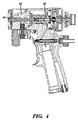
図4はエアパージガンの別の実施形態を示す図である。
図5はエアパージガンの他の別の実施形態を示す図である。
図6はエアパージガンの更に別の実施形態を示す図である。
FIG. 1 is a view showing a mechanical purge spray gun showing an apparatus of the present invention.
FIG. 2 shows a preferred embodiment of an air purge gun having a non-spray gun.
FIG. 3 is a view showing a preferred embodiment of an air purge gun having a spray gun.
FIG. 4 is a view showing another embodiment of the air purge gun.
FIG. 5 is a view showing another embodiment of the air purge gun.
FIG. 6 is a view showing still another embodiment of the air purge gun.
図1の機械式パージガン10は内部ポンピング機構によって溶剤を分配する。パージロッド12は小径ロッド14と大径ロッド16とからなる。パージロッド12が混合チャンバ18を通って後ろへ引かれると、小径ロッド14部分は大径ロッド16と置き換わり、溶剤入口20から溶剤を引き込むための真空が形成される。パージロッド12を前方へ移動させて機械式パージガン10を閉じると、溶剤は圧力の下で内部ポンプからパージロッド12の表面に沿って混合チャンバ18内に排出され、そこから混合された2つの成分材料と共に機械式パージガン10からパージされる。溶剤は塗布器内に内蔵されるか、又は常に機械式パージガンに配管されるかのどちらかである。
The mechanical purge gun 10 of FIG. 1 dispenses solvent by an internal pumping mechanism. The purge rod 12 includes a small diameter rod 14 and a large diameter rod 16. As the purge rod 12 is pulled back through the
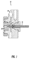
図2及び3の好ましい実施形態では、溶剤ピストン22は第1(非噴射−図2)位置と第2(噴射−図3)位置との間で往復する。第1位置では、溶剤ピストン22の後部22aに付与される高圧空気が溶剤ピストン22周りの溶剤穴24を閉じ、混合チャンバ26への溶剤の通過を妨げる。第2位置では、高圧空気が溶剤ピストン22の前部22bに付与されることで溶剤ピストン22をわずかに引っ込ませ、溶剤穴24を開けて溶剤入口28を閉じ、さらにある量の溶剤をパージ空気32と混合させて、溶剤出口30から混合チャンバ26に入れる。
In the preferred embodiment of FIGS. 2 and 3, the solvent piston 22 reciprocates between a first (non-injection—FIG. 2) position and a second (injection—FIG. 3) position. In the first position, the high pressure air applied to the rear 22 a of the solvent piston 22 closes the solvent hole 24 around the solvent piston 22 and prevents the solvent from passing into the mixing chamber 26. In the second position, high pressure air is applied to the front 22b of the solvent piston 22 to slightly retract the solvent piston 22, open the solvent hole 24, close the
図4の別の実施形態では、エアパージガンは内部注入ポンプ40によって引き金が離されたときに溶剤を自動的に分配する。分配された溶剤はパージ空気42と混合されて、混合チャンバ開口部44を通ってエアパージガンから排出される。
In another embodiment of FIG. 4, the air purge gun automatically dispenses the solvent when triggered by the
また、図5では、エアパージガンは内部ポンピング機構50によって引き金が離されたときに溶剤を自動的に分配する。分配された溶剤はパージ空気52と混合されて、混合チャンバ開口部54を通ってエアパージガンから排出される。
Also in FIG. 5, the air purge gun automatically dispenses the solvent when the trigger is released by the
図6の他の実施形態では、エアパージガンはベンチュリー効果60によって引き金が離されたときに溶剤を自動的に分配する。溶剤は空気のストリーム62内に注入されて、混合チャンバ開口部64を通って塗布器から排出される。溶剤は塗布器に内蔵されるか、又が常にエアパージガンに配管されるかのどちらかである。 In another embodiment of FIG. 6, the air purge gun automatically dispenses the solvent when the trigger is released by the venturi effect 60. Solvent is injected into the air stream 62 and exits the applicator through the mixing chamber opening 64. The solvent is either built into the applicator or is always piped to the air purge gun.
以下の特許請求の範囲によって規定される発明の精神及び範囲から逸脱することなく様々な変更及び修正を溶剤パージ機構に対して行うことができると考えられる。
It is contemplated that various changes and modifications can be made to the solvent purge mechanism without departing from the spirit and scope of the invention as defined by the following claims.
Claims (1)
溶剤源と、
前部及び後部を有するとともに且つ第1非噴射位置と第2噴射位置との間で移動可能な溶剤ピストンと、を含み、
前記第1位置では、高圧空気が前記後部に付与されることで前記溶剤ピストン周りの溶剤穴を閉じるため、前記混合チャンバへの溶剤の通過を妨げ、また、前記第2位置では、高圧空気が前部に付与されることで前記ガンの引き金を離して前記溶剤ピストンを引っ込ませ、前記溶剤穴を開けて前記溶剤源に接続された溶剤入口を閉じ、さらに、ある量の溶剤を前記パージ空気通路において混合させて、前記溶剤ピストンの前記前部側にある溶剤出口から前記混合チャンバに入れることができるように構成された複数成分スプレーガン。 A multi-component spray gun having a mixing chamber and a purge air passage ,
A solvent source;
A solvent piston having a front portion and a rear portion and movable between a first non-injection position and a second injection position,
In the first position, for closing the solvent holes around the solvent piston by high pressure air is applied to the rear, hinder the passage of solvent into the mixing chamber and, in the second position, high pressure air When applied to the front, the trigger of the gun is released to retract the solvent piston , the solvent hole is opened, the solvent inlet connected to the solvent source is closed, and a certain amount of solvent is removed from the purge air. A multi-component spray gun configured to mix in a passage and enter the mixing chamber from a solvent outlet on the front side of the solvent piston .
Applications Claiming Priority (3)
| Application Number | Priority Date | Filing Date | Title |
|---|---|---|---|
| US97130507P | 2007-09-11 | 2007-09-11 | |
| US60/971,305 | 2007-09-11 | ||
| PCT/US2008/075963 WO2009036129A1 (en) | 2007-09-11 | 2008-09-11 | Automatic solvent injection for plural component spray gun |
Publications (3)
| Publication Number | Publication Date |
|---|---|
| JP2010538815A JP2010538815A (en) | 2010-12-16 |
| JP2010538815A5 JP2010538815A5 (en) | 2013-07-18 |
| JP5406190B2 true JP5406190B2 (en) | 2014-02-05 |
Family
ID=40452466
Family Applications (1)
| Application Number | Title | Priority Date | Filing Date |
|---|---|---|---|
| JP2010524255A Active JP5406190B2 (en) | 2007-09-11 | 2008-09-11 | Multi-component spray gun for automatic solvent injection |
Country Status (11)
| Country | Link |
|---|---|
| US (1) | US8297531B2 (en) |
| EP (1) | EP2195117B1 (en) |
| JP (1) | JP5406190B2 (en) |
| KR (1) | KR101487047B1 (en) |
| CN (1) | CN101801538B (en) |
| AT (1) | ATE553850T1 (en) |
| AU (1) | AU2008298911B2 (en) |
| BR (1) | BRPI0816752A2 (en) |
| ES (1) | ES2383642T3 (en) |
| TW (1) | TWI453070B (en) |
| WO (1) | WO2009036129A1 (en) |
Families Citing this family (7)
| Publication number | Priority date | Publication date | Assignee | Title |
|---|---|---|---|---|
| TWI453070B (en) * | 2007-09-11 | 2014-09-21 | Graco Minnesota Inc | Automatic solvent injection for plural component spray gun |
| US20150072081A1 (en) * | 2013-09-10 | 2015-03-12 | Ryan Winston MONCHAMP | External coating method and apparatus |
| CN202146838U (en) * | 2011-05-30 | 2012-02-22 | 潘星钢 | Integral pneumatic spray gun |
| US9038929B1 (en) * | 2011-06-17 | 2015-05-26 | Pmc, Inc. | Air spray gun with pattern control tip |
| US9174362B2 (en) | 2011-07-12 | 2015-11-03 | Castagra Products, Inc. | Solvent-free plural component spraying system and method |
| CN111451222A (en) * | 2020-03-18 | 2020-07-28 | 成都东日瑞姆机械有限公司 | Polyurethane foaming equipment capable of adding powder components and pouring in multiple flow passages |
| BE1029916B1 (en) | 2022-06-10 | 2023-06-07 | Altachem Nv | Cleaning tools for foam guns |
Family Cites Families (25)
| Publication number | Priority date | Publication date | Assignee | Title |
|---|---|---|---|---|
| US2277928A (en) | 1940-09-20 | 1942-03-31 | Cortner M Hardy | Spray gun |
| CA938596A (en) * | 1968-01-08 | 1973-12-18 | E. Ives Frank | Liquid resin spray dispenser |
| US3653594A (en) * | 1970-11-17 | 1972-04-04 | Epec Ind Inc | Precision coatings spray gun |
| AU477284B2 (en) * | 1971-06-07 | 1976-10-21 | Ransburg Corporation | Plural component dispensing device and method |
| US3786990A (en) | 1972-07-17 | 1974-01-22 | Graco Inc | Plural component gun |
| FR2199666A6 (en) * | 1972-09-18 | 1974-04-12 | Ransburg Corp | |
| US3837575A (en) | 1973-08-27 | 1974-09-24 | Upjohn Co | Spray gun |
| US3945569A (en) * | 1974-10-25 | 1976-03-23 | Instapak Corporation | Foam dispensing apparatus |
| US4073664A (en) * | 1976-02-09 | 1978-02-14 | Olin Corporation | Automatically controlled cleaning fluid circuit for a foam generating apparatus and method |
| US4159079A (en) | 1977-08-24 | 1979-06-26 | Sealed Air Corporation | Dispenser |
| US4529126A (en) * | 1983-03-14 | 1985-07-16 | Frank Ives | External mixing spray gun |
| US4583691A (en) * | 1984-03-19 | 1986-04-22 | Freeman Chemical Corporation | Spray gun and solvent cleaning of same |
| US4791946A (en) * | 1987-07-16 | 1988-12-20 | Binks Manufacturing Company | Alternating selectable cleaning fluid to air purging system |
| US5170939A (en) * | 1990-09-27 | 1992-12-15 | Martin Olin H | Multiple component spray gun |
| JPH04156976A (en) * | 1990-10-18 | 1992-05-29 | Isao Shirayanagi | Device for forming resin coating |
| JPH07212Y2 (en) * | 1991-11-21 | 1995-01-11 | 岩田塗装機工業株式会社 | High-viscosity two-component hand spray gun cleaning device |
| US5299740A (en) | 1992-03-17 | 1994-04-05 | Binks Manufacturing Company | Plural component airless spray gun with mechanical purge |
| JP2002059045A (en) * | 2000-08-18 | 2002-02-26 | Asahi Sunac Corp | Cleaning mechanism of two-pack reactive curing type spray gun |
| US6533187B2 (en) | 2001-02-14 | 2003-03-18 | Illinois Tool Works Inc. | Adhesive dispensing gun |
| DE20104036U1 (en) | 2001-02-16 | 2001-06-21 | Wagner Wilhelm Wiwa | Spray gun |
| US20040038838A1 (en) | 2002-08-22 | 2004-02-26 | Mark Hammarth | Aerosol composition |
| US6905084B2 (en) | 2002-08-22 | 2005-06-14 | Illinois Tool Works Inc. | Airless application system and method of spraying |
| AU2003301667B2 (en) * | 2002-10-22 | 2008-01-24 | Graco Minnesota Inc. | Plural component spray gun for fast setting materials |
| US20050218556A1 (en) | 2004-04-02 | 2005-10-06 | Lear Corporation | Method and apparatus for spray forming polyurethane skins with a hydraulic mixing head |
| TWI453070B (en) * | 2007-09-11 | 2014-09-21 | Graco Minnesota Inc | Automatic solvent injection for plural component spray gun |
-
2008
- 2008-09-10 TW TW097134698A patent/TWI453070B/en not_active IP Right Cessation
- 2008-09-11 CN CN200880106295.3A patent/CN101801538B/en active Active
- 2008-09-11 US US12/673,562 patent/US8297531B2/en active Active
- 2008-09-11 KR KR1020107007707A patent/KR101487047B1/en active IP Right Grant
- 2008-09-11 ES ES08830747T patent/ES2383642T3/en active Active
- 2008-09-11 AU AU2008298911A patent/AU2008298911B2/en active Active
- 2008-09-11 BR BRPI0816752 patent/BRPI0816752A2/en not_active IP Right Cessation
- 2008-09-11 JP JP2010524255A patent/JP5406190B2/en active Active
- 2008-09-11 WO PCT/US2008/075963 patent/WO2009036129A1/en active Application Filing
- 2008-09-11 AT AT08830747T patent/ATE553850T1/en active
- 2008-09-11 EP EP08830747A patent/EP2195117B1/en active Active
Also Published As
| Publication number | Publication date |
|---|---|
| KR101487047B1 (en) | 2015-01-28 |
| TWI453070B (en) | 2014-09-21 |
| AU2008298911A1 (en) | 2009-03-19 |
| AU2008298911B2 (en) | 2012-12-20 |
| CN101801538B (en) | 2014-04-16 |
| TW200932366A (en) | 2009-08-01 |
| US8297531B2 (en) | 2012-10-30 |
| EP2195117A1 (en) | 2010-06-16 |
| BRPI0816752A2 (en) | 2015-03-17 |
| WO2009036129A1 (en) | 2009-03-19 |
| US20110101129A1 (en) | 2011-05-05 |
| EP2195117B1 (en) | 2012-04-18 |
| KR20100075489A (en) | 2010-07-02 |
| ATE553850T1 (en) | 2012-05-15 |
| EP2195117A4 (en) | 2010-09-22 |
| ES2383642T3 (en) | 2012-06-25 |
| JP2010538815A (en) | 2010-12-16 |
| CN101801538A (en) | 2010-08-11 |
Similar Documents
| Publication | Publication Date | Title |
|---|---|---|
| JP5406190B2 (en) | Multi-component spray gun for automatic solvent injection | |
| RU2417127C2 (en) | Sprayer gun | |
| CA2948886C (en) | Trigger-type liquid dispenser | |
| KR200428831Y1 (en) | spray gun | |
| CN108348931A (en) | Spray nozzle device | |
| AU2018395431A1 (en) | Pneumatic material spray gun | |
| JPS58263A (en) | Multi-component spray gun | |
| JP2010538815A5 (en) | ||
| JP2004068773A (en) | Coating supply syringe pump | |
| TW201436879A (en) | Pressure-assist hopper for integrated handheld texture sprayer | |
| JP2007014912A (en) | Coater | |
| KR20200001933A (en) | spray gun for painting | |
| KR101363553B1 (en) | water-soluble spray gun | |
| JP5773808B2 (en) | Spray gun for paint | |
| JP2002059045A (en) | Cleaning mechanism of two-pack reactive curing type spray gun | |
| JPH07212Y2 (en) | High-viscosity two-component hand spray gun cleaning device | |
| JP3148974B2 (en) | Spray gun for painting | |
| KR101776030B1 (en) | Apparatus for spraying fluid | |
| KR890005080B1 (en) | Atomizer | |
| JPS6084176A (en) | Nozzle apparatus | |
| JPH0760168A (en) | Spray gun | |
| TW201233451A (en) | Material spraying mechanism for spray gun or pen | |
| WO2010100641A1 (en) | Multi-purpose lid assembly interfaceable with a paint spray gun |
Legal Events
| Date | Code | Title | Description |
|---|---|---|---|
| A621 | Written request for application examination |
Free format text: JAPANESE INTERMEDIATE CODE: A621 Effective date: 20110527 |
|
| A977 | Report on retrieval |
Free format text: JAPANESE INTERMEDIATE CODE: A971007 Effective date: 20130312 |
|
| A131 | Notification of reasons for refusal |
Free format text: JAPANESE INTERMEDIATE CODE: A131 Effective date: 20130319 |
|
| A524 | Written submission of copy of amendment under article 19 pct |
Free format text: JAPANESE INTERMEDIATE CODE: A524 Effective date: 20130531 |
|
| A521 | Request for written amendment filed |
Free format text: JAPANESE INTERMEDIATE CODE: A523 Effective date: 20130604 |
|
| TRDD | Decision of grant or rejection written | ||
| A01 | Written decision to grant a patent or to grant a registration (utility model) |
Free format text: JAPANESE INTERMEDIATE CODE: A01 Effective date: 20131029 |
|
| A61 | First payment of annual fees (during grant procedure) |
Free format text: JAPANESE INTERMEDIATE CODE: A61 Effective date: 20131031 |
|
| R150 | Certificate of patent or registration of utility model |
Ref document number: 5406190 Country of ref document: JP Free format text: JAPANESE INTERMEDIATE CODE: R150 |
|
| R250 | Receipt of annual fees |
Free format text: JAPANESE INTERMEDIATE CODE: R250 |
|
| R250 | Receipt of annual fees |
Free format text: JAPANESE INTERMEDIATE CODE: R250 |
|
| R250 | Receipt of annual fees |
Free format text: JAPANESE INTERMEDIATE CODE: R250 |
|
| R250 | Receipt of annual fees |
Free format text: JAPANESE INTERMEDIATE CODE: R250 |
|
| R250 | Receipt of annual fees |
Free format text: JAPANESE INTERMEDIATE CODE: R250 |
|
| R250 | Receipt of annual fees |
Free format text: JAPANESE INTERMEDIATE CODE: R250 |
|
| R250 | Receipt of annual fees |
Free format text: JAPANESE INTERMEDIATE CODE: R250 |
|
| R250 | Receipt of annual fees |
Free format text: JAPANESE INTERMEDIATE CODE: R250 |