JP5406086B2 - Paper float detection device and ink jet recording device - Google Patents
Paper float detection device and ink jet recording device Download PDFInfo
- Publication number
- JP5406086B2 JP5406086B2 JP2010060918A JP2010060918A JP5406086B2 JP 5406086 B2 JP5406086 B2 JP 5406086B2 JP 2010060918 A JP2010060918 A JP 2010060918A JP 2010060918 A JP2010060918 A JP 2010060918A JP 5406086 B2 JP5406086 B2 JP 5406086B2
- Authority
- JP
- Japan
- Prior art keywords
- detection
- light
- paper
- light receiving
- parallel plate
- Prior art date
- Legal status (The legal status is an assumption and is not a legal conclusion. Google has not performed a legal analysis and makes no representation as to the accuracy of the status listed.)
- Active
Links
- 238000001514 detection method Methods 0.000 title claims description 373
- 238000007667 floating Methods 0.000 claims description 148
- 230000002093 peripheral effect Effects 0.000 claims description 21
- 230000005856 abnormality Effects 0.000 claims description 20
- 238000011144 upstream manufacturing Methods 0.000 claims description 4
- 239000011521 glass Substances 0.000 description 104
- 239000000976 ink Substances 0.000 description 99
- 238000012546 transfer Methods 0.000 description 71
- 230000032258 transport Effects 0.000 description 71
- 239000007788 liquid Substances 0.000 description 60
- 238000012545 processing Methods 0.000 description 45
- 238000001035 drying Methods 0.000 description 43
- 238000000034 method Methods 0.000 description 36
- 230000008569 process Effects 0.000 description 27
- 230000003287 optical effect Effects 0.000 description 12
- 238000003825 pressing Methods 0.000 description 11
- 238000012423 maintenance Methods 0.000 description 9
- 238000004891 communication Methods 0.000 description 7
- 230000009471 action Effects 0.000 description 4
- 238000006243 chemical reaction Methods 0.000 description 4
- 239000003086 colorant Substances 0.000 description 4
- 238000006073 displacement reaction Methods 0.000 description 4
- 230000006870 function Effects 0.000 description 4
- 230000004044 response Effects 0.000 description 4
- 230000002159 abnormal effect Effects 0.000 description 3
- 230000007423 decrease Effects 0.000 description 3
- 238000010586 diagram Methods 0.000 description 3
- 238000007689 inspection Methods 0.000 description 3
- 229920005992 thermoplastic resin Polymers 0.000 description 3
- XLYOFNOQVPJJNP-UHFFFAOYSA-N water Substances O XLYOFNOQVPJJNP-UHFFFAOYSA-N 0.000 description 3
- 238000013459 approach Methods 0.000 description 2
- 230000000740 bleeding effect Effects 0.000 description 2
- 239000000463 material Substances 0.000 description 2
- 230000007246 mechanism Effects 0.000 description 2
- 239000002904 solvent Substances 0.000 description 2
- 230000004931 aggregating effect Effects 0.000 description 1
- 230000000903 blocking effect Effects 0.000 description 1
- 238000007664 blowing Methods 0.000 description 1
- 230000008859 change Effects 0.000 description 1
- 238000004140 cleaning Methods 0.000 description 1
- 239000011248 coating agent Substances 0.000 description 1
- 238000000576 coating method Methods 0.000 description 1
- 230000002950 deficient Effects 0.000 description 1
- 238000009792 diffusion process Methods 0.000 description 1
- 238000007599 discharging Methods 0.000 description 1
- 230000000694 effects Effects 0.000 description 1
- 238000001704 evaporation Methods 0.000 description 1
- 230000008020 evaporation Effects 0.000 description 1
- 238000010438 heat treatment Methods 0.000 description 1
- 239000004615 ingredient Substances 0.000 description 1
- 238000005259 measurement Methods 0.000 description 1
- 239000002994 raw material Substances 0.000 description 1
- 238000001454 recorded image Methods 0.000 description 1
- 238000011084 recovery Methods 0.000 description 1
- 238000005096 rolling process Methods 0.000 description 1
- 238000005507 spraying Methods 0.000 description 1
- 238000003860 storage Methods 0.000 description 1
- 238000003466 welding Methods 0.000 description 1
Images


Classifications
-
- B—PERFORMING OPERATIONS; TRANSPORTING
- B41—PRINTING; LINING MACHINES; TYPEWRITERS; STAMPS
- B41J—TYPEWRITERS; SELECTIVE PRINTING MECHANISMS, i.e. MECHANISMS PRINTING OTHERWISE THAN FROM A FORME; CORRECTION OF TYPOGRAPHICAL ERRORS
- B41J29/00—Details of, or accessories for, typewriters or selective printing mechanisms not otherwise provided for
- B41J29/38—Drives, motors, controls or automatic cut-off devices for the entire printing mechanism
-
- B—PERFORMING OPERATIONS; TRANSPORTING
- B65—CONVEYING; PACKING; STORING; HANDLING THIN OR FILAMENTARY MATERIAL
- B65H—HANDLING THIN OR FILAMENTARY MATERIAL, e.g. SHEETS, WEBS, CABLES
- B65H5/00—Feeding articles separated from piles; Feeding articles to machines
- B65H5/08—Feeding articles separated from piles; Feeding articles to machines by grippers, e.g. suction grippers
- B65H5/12—Revolving grippers, e.g. mounted on arms, frames or cylinders
-
- B—PERFORMING OPERATIONS; TRANSPORTING
- B65—CONVEYING; PACKING; STORING; HANDLING THIN OR FILAMENTARY MATERIAL
- B65H—HANDLING THIN OR FILAMENTARY MATERIAL, e.g. SHEETS, WEBS, CABLES
- B65H7/00—Controlling article feeding, separating, pile-advancing, or associated apparatus, to take account of incorrect feeding, absence of articles, or presence of faulty articles
- B65H7/02—Controlling article feeding, separating, pile-advancing, or associated apparatus, to take account of incorrect feeding, absence of articles, or presence of faulty articles by feelers or detectors
- B65H7/14—Controlling article feeding, separating, pile-advancing, or associated apparatus, to take account of incorrect feeding, absence of articles, or presence of faulty articles by feelers or detectors by photoelectric feelers or detectors
-
- B—PERFORMING OPERATIONS; TRANSPORTING
- B41—PRINTING; LINING MACHINES; TYPEWRITERS; STAMPS
- B41J—TYPEWRITERS; SELECTIVE PRINTING MECHANISMS, i.e. MECHANISMS PRINTING OTHERWISE THAN FROM A FORME; CORRECTION OF TYPOGRAPHICAL ERRORS
- B41J25/00—Actions or mechanisms not otherwise provided for
- B41J2025/008—Actions or mechanisms not otherwise provided for comprising a plurality of print heads placed around a drum
-
- B—PERFORMING OPERATIONS; TRANSPORTING
- B65—CONVEYING; PACKING; STORING; HANDLING THIN OR FILAMENTARY MATERIAL
- B65H—HANDLING THIN OR FILAMENTARY MATERIAL, e.g. SHEETS, WEBS, CABLES
- B65H2511/00—Dimensions; Position; Numbers; Identification; Occurrences
- B65H2511/20—Location in space
- B65H2511/24—Irregularities, e.g. in orientation or skewness
-
- B—PERFORMING OPERATIONS; TRANSPORTING
- B65—CONVEYING; PACKING; STORING; HANDLING THIN OR FILAMENTARY MATERIAL
- B65H—HANDLING THIN OR FILAMENTARY MATERIAL, e.g. SHEETS, WEBS, CABLES
- B65H2553/00—Sensing or detecting means
- B65H2553/40—Sensing or detecting means using optical, e.g. photographic, elements
- B65H2553/41—Photoelectric detectors
- B65H2553/412—Photoelectric detectors in barrier arrangements, i.e. emitter facing a receptor element
-
- B—PERFORMING OPERATIONS; TRANSPORTING
- B65—CONVEYING; PACKING; STORING; HANDLING THIN OR FILAMENTARY MATERIAL
- B65H—HANDLING THIN OR FILAMENTARY MATERIAL, e.g. SHEETS, WEBS, CABLES
- B65H2553/00—Sensing or detecting means
- B65H2553/40—Sensing or detecting means using optical, e.g. photographic, elements
- B65H2553/44—Involving light guide, e.g. optical fibres
-
- B—PERFORMING OPERATIONS; TRANSPORTING
- B65—CONVEYING; PACKING; STORING; HANDLING THIN OR FILAMENTARY MATERIAL
- B65H—HANDLING THIN OR FILAMENTARY MATERIAL, e.g. SHEETS, WEBS, CABLES
- B65H2557/00—Means for control not provided for in groups B65H2551/00 - B65H2555/00
- B65H2557/50—Use of particular electromagnetic waves, e.g. light, radiowaves or microwaves
- B65H2557/51—Laser
-
- B—PERFORMING OPERATIONS; TRANSPORTING
- B65—CONVEYING; PACKING; STORING; HANDLING THIN OR FILAMENTARY MATERIAL
- B65H—HANDLING THIN OR FILAMENTARY MATERIAL, e.g. SHEETS, WEBS, CABLES
- B65H2801/00—Application field
- B65H2801/03—Image reproduction devices
- B65H2801/15—Digital printing machines
Description
本発明は、用紙浮き検出装置及びインクジェット記録装置に係り、特に検出高さを可変できる用紙浮き検出装置及びインクジェット記録装置に関する。 The present invention relates to a paper floating detection device and an ink jet recording apparatus, and more particularly to a paper floating detection device and an ink jet recording apparatus that can vary the detection height.
インクジェット記録装置では、所定の搬送経路を搬送される用紙に対してインクジェットヘッドからインクの液滴を吐出させて、用紙の記録面に所定の画像を記録する。このようなインクジェット記録装置において、搬送される用紙が搬送面から浮いていると、ヘッドのノズル面から用紙の記録面までの距離(スローディスタンス)が変化し、記録品位が低下したり、用紙がヘッドのノズル面に擦れて、ノズル面を傷めたりするという問題がある。このため、インクジェット記録装置では、用紙の搬送経路に用紙浮き検出装置を設置し、規定値以上の浮きが検出された場合には、搬送を停止するなどの処理を行うようにしている。 In an ink jet recording apparatus, ink droplets are ejected from an ink jet head onto a sheet conveyed on a predetermined conveyance path, and a predetermined image is recorded on a recording surface of the sheet. In such an ink jet recording apparatus, when the paper to be transported floats from the transport surface, the distance (slow distance) from the nozzle surface of the head to the recording surface of the paper changes, and the recording quality decreases or the paper There is a problem of rubbing against the nozzle surface of the head and damaging the nozzle surface. For this reason, in the ink jet recording apparatus, a sheet floating detection device is installed in the sheet conveyance path, and when a float higher than a specified value is detected, processing such as stopping conveyance is performed.
従来、用紙の浮きの検出は、用紙の搬送経路を挟んで互いに対向するように投光部と受光部とを設置し、投光部から受光部に向けて搬送面から所定高さの位置に検出ビームを出射し、その検出ビームの受光の有無を検出して行われていた。すなわち、用紙に浮きが生じると、用紙が検出ビームの受光を遮るので、これによって、用紙の浮きの有無を判定するようにしている(たとえば、特許文献1、2等)。 Conventionally, the detection of paper floating has been performed by installing a light projecting unit and a light receiving unit so as to face each other across the paper transport path, and at a predetermined height from the transport surface from the light projecting unit toward the light receiving unit. This is done by emitting a detection beam and detecting whether the detection beam is received or not. In other words, when the sheet floats, the sheet blocks light reception of the detection beam, and therefore, the presence or absence of the sheet floating is determined (for example, Patent Documents 1 and 2).
ところで、インクジェット記録装置で記録する用紙には、さまざまな紙厚のものが存在する。したがって、使用する用紙の紙厚が変更された場合には、その紙厚に合わせて浮きの検出高さも変更する必要がある。 By the way, there are papers of various paper thicknesses to be recorded by the ink jet recording apparatus. Therefore, when the paper thickness of the paper to be used is changed, it is necessary to change the detection height of the float according to the paper thickness.
特許文献3には、インクジェットヘッドとともに昇降する部材に投光部と受光部を設け、インクジェットヘッドの昇降に合わせて浮きの検出高さを変更する技術が提案されている。 Patent Document 3 proposes a technique in which a light projecting unit and a light receiving unit are provided on a member that moves up and down together with an inkjet head, and the detection height of the float is changed in accordance with the elevation of the inkjet head.
しかしながら、特許文献3に記載の技術では、インクジェットヘッドを昇降させて検出高さを変える構成のため、微調整が難しいという欠点がある。 However, the technique described in Patent Document 3 has a drawback that fine adjustment is difficult because of the configuration in which the detection height is changed by moving the inkjet head up and down.
また、インクジェットヘッドに捩れが生じると、投光部と受光部との間に位置ずれが生じ、検出精度が低下するという欠点もある。 In addition, when the ink jet head is twisted, there is a drawback in that a positional deviation occurs between the light projecting unit and the light receiving unit, and the detection accuracy is lowered.
さらに、インクジェットヘッドが定期的にメンテナンス部に移動してメンテナンスを実施する装置では、インクジェットヘッドが移動するたびに検出高さにズレが生じる場合があり、高精度な検出を安定して行うことができないという欠点もある。 Furthermore, in an apparatus in which the inkjet head periodically moves to the maintenance unit and performs maintenance, the detection height may be shifted each time the inkjet head moves, and high-precision detection can be performed stably. There is also a drawback that it cannot be done.
また、インクジェットヘッドの下部に投光部と受光部とが設けられるため、インクジェットヘッドを退避させる際に退避量を大きくとらなければならず、装置が大型化するという欠点もある。 In addition, since the light projecting unit and the light receiving unit are provided below the ink jet head, the retract amount must be increased when the ink jet head is retracted, and there is a disadvantage that the apparatus becomes large.
本発明は、このような事情に鑑みてなされたもので、浮きの検出高さを高精度に調整でき、高精度な検出を安定して行うことができる用紙浮き検出装置及びインクジェット記録装置を提供することを目的とする。 The present invention has been made in view of such circumstances, and provides a sheet floating detection apparatus and an ink jet recording apparatus that can adjust the detection height of floating with high accuracy and can stably perform highly accurate detection. The purpose is to do.
請求項1に係る発明は、前記目的を達成するために、所定の搬送面上を所定の搬送経路に沿って搬送される用紙の浮きを検出する用紙浮き検出装置において、前記搬送経路を挟んで互いに対向して配置される投光部と受光部とを有し、前記搬送面から所定高さの位置に前記搬送面と平行な検出ビームを前記投光部から前記受光部に向けて出射し、前記受光部での前記検出ビームの受光の有無を検出して、前記用紙の浮きの有無を検出する用紙浮き検出手段と、前記投光部から出射された前記検出ビームが透過するように前記投光部の前段に配置されるとともに、前記搬送面と平行し且つ前記検出ビームと直交する軸の周りを回動自在に設けられ、回動することにより内部を透過して出射する前記検出ビームの高さを可変させる投光用平行平板と、前記投光用平行平板を回転駆動する投光用平行平板回転駆動手段と、を備えたことを特徴とする用紙浮き検出装置を提供する。 According to a first aspect of the present invention, in order to achieve the above object, in a paper floating detection device that detects the floating of a paper transported along a predetermined transport path on a predetermined transport surface, the transport path is sandwiched between them. A light projecting unit and a light receiving unit arranged to face each other, and a detection beam parallel to the transport surface is emitted from the light projecting unit toward the light receiving unit at a predetermined height from the transport surface. Detecting the presence or absence of the detection beam at the light receiving unit to detect the presence or absence of the paper floating, and the detection beam emitted from the light projecting unit transmits the detection beam. The detection beam that is arranged in front of the light projecting unit, is rotatably provided around an axis that is parallel to the transport surface and orthogonal to the detection beam, and is transmitted through and emitted through the rotation. Parallel plate for floodlight with variable height Provides a paper floating detection device is characterized in that and a floodlight parallel plate rotation driving means for rotating the parallel plate for the light projection.
本発明によれば、投光部の前段に配置された投光用平行平板を回動させることにより、用紙の浮きの検出高さ(=検出ビームの搬送面からの高さ)を変えることができる。検出ビームの光軸に対して投光用平行平板を傾けると、屈折の作用により、投光用平行平板から出射される検出ビームの出射位置が上方又は下方にシフトする。検出ビームの出射位置は、投光用平行平板に入射する検出ビームの入射角によって変位し、入射角は投光用平行平板の回転量に応じて変化する。したがって、投光用平行平板を回動させることにより、検出ビームの出射位置を変えることができ、検出ビームの高さ(用紙の浮きの検出高さ)を変えることができる。このように投光用平行平板の屈折の作用を利用して、検出ビームの光軸をシフトさせることにより、浮きの検出高さを簡単かつ高精度に調整することができる。また、他の構成に依存しないので、長期間安定した検出を行うことができる。 According to the present invention, the detection height of the floating of the paper (= the height from the conveyance surface of the detection beam) can be changed by rotating the light-projecting parallel flat plate disposed in front of the light-projecting unit. it can. When the light projecting parallel plate is tilted with respect to the optical axis of the detection beam, the exit position of the detection beam emitted from the light projecting parallel plate is shifted upward or downward by the action of refraction. The emission position of the detection beam is displaced by the incident angle of the detection beam incident on the light projecting parallel plate, and the incident angle changes according to the rotation amount of the light projecting parallel plate. Therefore, by rotating the light projecting parallel plate, the emission position of the detection beam can be changed, and the height of the detection beam (detection height of the paper floating) can be changed. In this way, the detection height of the floating can be adjusted easily and with high accuracy by shifting the optical axis of the detection beam by utilizing the action of refraction of the projecting parallel plate. In addition, since it does not depend on other configurations, stable detection can be performed for a long time.
請求項2に係る発明は、前記目的を達成するために、前記投光用平行平板を透過した前記検出ビームが透過するように前記受光部の前段に配置されるとともに、前記搬送面と平行し且つ前記検出ビームと直交する軸の周りを回動自在に設けられ、回動することにより内部を透過して出射する前記検出ビームの高さを可変させる受光用平行平板と、前記受光用平行平板を回転駆動する受光用平行平板回転駆動手段と、を備えたことを特徴とする請求項1に記載の用紙浮き検出装置を提供する。
In order to achieve the above object, the invention according to
本発明によれば、受光側にも受光用平行平板が設けられ、検出ビームの高さを調整することができる。これにより、より高精度な検出を行うことができる。 According to the present invention, the light receiving parallel plate is also provided on the light receiving side, and the height of the detection beam can be adjusted. Thereby, more accurate detection can be performed.
請求項3に係る発明は、前記目的を達成するために、前記受光部と前記受光用平行平板との間に受光用アパーチャが配置されることを特徴とする請求項2に記載の用紙浮き検出装置を提供する。 The invention according to claim 3 is characterized in that a light receiving aperture is disposed between the light receiving unit and the light receiving parallel plate to achieve the above object. Providing equipment.
本発明によれば、受光部と受光用平行平板との間にアパーチャ(受光用アパーチャ)が配置される。これにより、投光部と受光部との間で多少のズレが生じた場合であっても、アパーチャで検出ビームの光軸の位置を決めることができるので、ロバストネスに強い構造とすることができる。 According to the present invention, the aperture (light receiving aperture) is disposed between the light receiving portion and the light receiving parallel plate. As a result, even if there is a slight deviation between the light projecting unit and the light receiving unit, the position of the optical axis of the detection beam can be determined by the aperture, so that a robust structure can be obtained. .
請求項4に係る発明は、前記目的を達成するために、前記投光部と前記投光用平行平板との間に投光用アパーチャが配置されることを特徴とする請求項3に記載の用紙浮き検出装置を提供する。 The invention according to claim 4 is characterized in that, in order to achieve the object, a light projection aperture is disposed between the light projecting portion and the light projecting parallel plate. A paper floating detection device is provided.
本発明によれば、投光部と投光用平行平板との間にもアパーチャ(投光用アパーチャ)が配置される。これにより、より高精度な検出を行うことができる。 According to the present invention, the aperture (projection aperture) is also disposed between the light projecting unit and the projecting parallel plate. Thereby, more accurate detection can be performed.
請求項5に係る発明は、前記目的を達成するために、前記受光用アパーチャの開口面積が、前記投光用アパーチャの開口面積よりも小さく設定されることを特徴とする請求項4に記載の用紙浮き検出装置を提供する。 The invention according to claim 5 is characterized in that, in order to achieve the object, an opening area of the light receiving aperture is set smaller than an opening area of the light projecting aperture. A paper floating detection device is provided.
本発明によれば、受光用アパーチャの開口面積が、投光用アパーチャの開口面積よりも小さく設定される。これにより、反射による回り込み光の影響を極力小さくすることができ、高精度な検出を行うことができる。 According to the present invention, the opening area of the light receiving aperture is set smaller than the opening area of the light projecting aperture. Thereby, the influence of the sneak light caused by the reflection can be reduced as much as possible, and highly accurate detection can be performed.
請求項6に係る発明は、前記目的を達成するために、前記用紙浮き検出手段の検出結果に基づいて、前記投光用平行平板回転駆動手段の駆動を制御することにより、前記検出ビームの高さを調整する検出高さ調整手段を備え、該検出高さ調整手段は、前記受光部で前記検出ビームが受光されている状態で前記投光用平行平板を第1の方向に回転させ、前記受光部で前記検出ビームが受光されなくなったら前記投光用平行平板の回転を停止し、該位置を基準位置として、該基準位置から前記投光用平行平板を前記第1の方向とは逆方向の第2の方向に所定量回転させる動作を行って、前記検出ビームの高さを調整することを特徴とする請求項1〜5のいずれか一項に記載の用紙浮き検出装置を提供する。 In order to achieve the above object, the invention according to claim 6 controls the drive of the light projecting parallel plate rotation driving means based on the detection result of the paper floating detection means, thereby increasing the height of the detection beam. Detecting height adjusting means for adjusting the height, wherein the detecting height adjusting means rotates the light projecting parallel plate in a first direction in a state where the detection beam is received by the light receiving unit, and When the detection beam is no longer received by the light receiving unit, the rotation of the light projecting parallel plate is stopped, and the light projecting parallel plate is opposite to the first direction from the reference position with the position as a reference position. The sheet floating detection device according to claim 1, wherein the height of the detection beam is adjusted by performing an operation of rotating the detection beam by a predetermined amount in the second direction.
本発明によれば、位置調整の基準となる搬送面の位置を検出して、検出ビームの高さ(用紙の浮きの検出高さ)を設定するので、高精度に用紙の浮きの検出高さを設定することができる。 According to the present invention, the height of the detection surface is detected and the height of the detection beam is set (detection height of the paper floating). Can be set.
請求項7に係る発明は、前記目的を達成するために、前記用紙浮き検出手段の検出結果に基づいて、前記投光用平行平板回転駆動手段と前記受光用平行平板回転駆動手段の駆動を制御することにより、前記検出ビームの高さを調整する検出高さ調整手段を備え、該検出高さ調整手段は、前記受光部で前記検出ビームが受光されている状態で前記投光用平行平板を第1の方向に回転させて、前記検出ビームを前記搬送面に近づく方向に移動させ、前記検出ビームが前記搬送面で遮光されることによって、前記受光部で前記検出ビームが受光されなくなったら前記投光用平行平板の回転を停止し、次いで、前記検出ビームが前記受光部で受光されるように、前記第1の方向とは逆方向の第2の方向に前記投光用平行平板を回転させて、前記搬送面から所定距離離れた位置に前記検出ビームを移動させ、次いで、前記受光用平行平板を前記第2の方向に回転させ、前記受光部で前記検出ビームが受光されなくなったら前記受光用平行平板の回転を停止し、当該位置を基準位置として、前記検出ビームが所定の検出高さの位置に位置するように、前記基準位置から前記受光用平行平板を前記第1の方向に回転させるとともに、前記投光用平行平板を前記第2の方向に回転させる動作を行って、前記検出ビームの高さを調整することを特徴とする請求項2〜5のいずれか一項に記載の用紙浮き検出装置を提供する。 In order to achieve the above object, the invention according to claim 7 controls driving of the light projecting parallel plate rotation driving means and the light receiving parallel plate rotation driving means based on the detection result of the sheet floating detection means. Detecting height adjustment means for adjusting the height of the detection beam, wherein the detection height adjustment means is configured to move the parallel plate for light projection in a state where the detection beam is received by the light receiving portion. When the detection beam is not received by the light receiving unit by rotating in the first direction, moving the detection beam in a direction approaching the transfer surface, and blocking the detection beam by the transfer surface, stop the rotation of the parallel plate light projecting, then the detection beam as is received by the light receiving portion, the first direction and the parallel plate for the light projecting times in a second direction opposite direction by rolling, said conveying surface Moving the detection beam Luo predetermined distance away, then the light receiving parallel plate is rotated in the second direction, rotation of the light receiving parallel plate When the detection beam by the light receiving unit is no longer being received the stop, as a reference position the position, so that the detection beam is positioned at the position of the predetermined detection level, causes the rotation of the light receiving parallel plate in the first direction from the reference position, the the parallel plate floodlight performs an operation of rotating in the second direction, the paper floating detection according to any one of claims 2-5, characterized in that for adjusting the height of the detection beam Providing equipment.
本発明によれば、位置調整の基準となる搬送面の位置を検出して、検出ビームの高さ(用紙の浮きの検出高さ)を設定するので、高精度に用紙の浮きの検出高さを設定することができる。 According to the present invention, the height of the detection surface is detected and the height of the detection beam is set (detection height of the paper floating). Can be set.
請求項8に係る発明は、前記目的を達成するために、前記検出高さ調整手段は、所定の投光用始点位置から前記動作を開始し、前記投光用始点位置から前記基準位置までの前記投光用平行平板の回転量を投光用基準回転量として検出する投光用基準回転量検出手段と、前記投光用基準回転量検出手段で検出された投光用基準回転量を閾値と比較し、装置異常の有無を判定する異常判定手段と、を備えたことを特徴とする請求項6又は7に記載の用紙浮き検出装置を提供する。 The invention according to claim 8, in order to achieve the object, the inspection Dedaka adjusting means starts the operation from a predetermined light projection start position, to the reference position from the start position for the projection The projection reference rotation amount detecting means for detecting the rotation amount of the light projecting parallel plate as the projection reference rotation amount, and the projection reference rotation amount detected by the projection reference rotation amount detection means. The paper floating detection device according to claim 6, further comprising an abnormality determination unit that compares the threshold value with the threshold value to determine whether the device is abnormal.
本発明によれば、所定の投光用始点位置から基準位置までの投光用平行平板の回転量を投光用基準回転量として検出し、この投光用基準回転量に基づいて装置異常を判定する。これにより、装置異常を未然に防止することができ、安定した検出を行うことができる。 According to the present invention, the rotation amount of the light projecting parallel plate from the predetermined light projection start point position to the reference position is detected as the light projection reference rotation amount, and the apparatus abnormality is detected based on the light projection reference rotation amount. judge. As a result, it is possible to prevent an apparatus abnormality in advance and to perform stable detection.
請求項9に係る発明は、前記目的を達成するために、前記検出高さ調整手段は、所定の投光用始点位置及び受光用始点位置から前記動作を開始し、前記投光用始点位置から前記基準位置までの前記投光用平行平板の回転量を投光用基準回転量として検出する投光用基準回転量検出手段と、前記受光用始点位置から前記基準位置までの受光用平行平板の回転量を受光用基準回転量として検出する受光用基準回転量検出手段と、前記投光用基準回転量検出手段で検出された投光用基準回転量を閾値と比較するとともに、前記受光用基準回転量検出手段で検出された受光用基準回転量を閾値と比較し、装置異常の有無を判定する異常判定手段と、を備えたことを特徴とする請求項7に記載の用紙浮き検出装置を提供する。
The invention according to
本発明によれば、所定の投光用始点位置から基準位置までの投光用平行平板の回転量を投光用基準回転量として検出するとともに、所定の受光用始点位置から基準位置までの受光用平行平板の回転量を受光用基準回転量として検出し、この投光用基準回転量及び受光用基準回転量に基づいて装置異常を判定する。これにより、装置異常を未然に防止することができ、安定した検出を行うことができる。 According to the present invention, the rotation amount of the light projecting parallel plate from the predetermined light projection start point position to the reference position is detected as the light projection reference rotation amount, and the light reception from the predetermined light reception start point position to the reference position is detected. The rotation amount of the parallel plate for light detection is detected as the reference rotation amount for light reception, and an apparatus abnormality is determined based on the reference rotation amount for light projection and the reference rotation amount for light reception. As a result, it is possible to prevent an apparatus abnormality in advance and to perform stable detection.
請求項10に係る発明は、前記目的を達成するために、前記検出高さ調整手段は、前記動作を複数回繰り返し行って前記検出ビームの高さを調整することを特徴とする請求項6〜9のいずれか一項に記載の用紙浮き検出装置を提供する。
The invention according to
本発明によれば、検出ビームの高さ位置の調整動作を複数回繰り返し行って、検出ビームの高さを調整する。これにより、より高精度な調整を行うことができる。 According to the present invention, the height of the detection beam is adjusted by repeatedly adjusting the height position of the detection beam a plurality of times. As a result, more accurate adjustment can be performed.
請求項11に係る発明は、前記目的を達成するために、前記投光部から前記受光部に向けて出射される検出ビームが、前記用紙の搬送方向と直交する方向に対して所定角度傾斜するように、前記投光部と前記受光部とが設置されることを特徴とする請求項1〜10のいずれか一項に記載の用紙浮き検出装置を提供する。 According to an eleventh aspect of the present invention, in order to achieve the above object, a detection beam emitted from the light projecting unit toward the light receiving unit is inclined at a predetermined angle with respect to a direction orthogonal to the conveyance direction of the paper. As described above, the paper floating detection device according to claim 1, wherein the light projecting unit and the light receiving unit are installed.
本発明によれば、投光部から受光部に向けて出射される検出ビームが、用紙の搬送方向と直交する方向に対して所定角度傾斜(0.3°〜2°傾斜)するように、投光部と受光部とが設置される。これにより、用紙の搬送方向と直交する方向の浮きも精度よく検出することができる。 According to the present invention, the detection beam emitted from the light projecting unit toward the light receiving unit is inclined at a predetermined angle (0.3 ° to 2 °) with respect to a direction orthogonal to the paper transport direction. A light projecting unit and a light receiving unit are installed. Accordingly, it is possible to accurately detect the floating in the direction orthogonal to the sheet conveyance direction.
請求項12に係る発明は、前記目的を達成するために、用紙を搬送する搬送手段と、前記搬送手段によって搬送される用紙の記録面にインクを打滴して画像を描画するインクジェットヘッドと、前記インクジェットヘッドの上流側に設置され、前記搬送手段の搬送面からの前記用紙の浮きを検出する請求項1〜11のいずれか一項に記載の用紙浮き検出装置と、前記用紙浮き検出装置の検出結果に基づいて、前記用紙の搬送異常を判定する搬送異常判定手段と、を備えたことを特徴とするインクジェット記録装置を提供する。 In order to achieve the above object, the invention according to claim 12 includes a transport unit that transports paper, an ink jet head that draws an ink on a recording surface of the paper transported by the transport unit, and draws an image; The sheet floating detection device according to any one of claims 1 to 11, wherein the sheet floating detection device is installed upstream of the inkjet head and detects the sheet floating from the conveyance surface of the conveyance unit. An inkjet recording apparatus comprising: a conveyance abnormality determining unit that determines a conveyance abnormality of the sheet based on a detection result.
本発明によれば、インクジェット記録装置に用紙浮き検出装置が組み込まれ、記録中の用紙の浮きが用紙浮き検出装置によって検出される。 According to the present invention, a paper floating detection device is incorporated in an ink jet recording apparatus, and the floating of the paper being recorded is detected by the paper floating detection device.
請求項13に係る発明は、前記目的を達成するために、前記搬送手段は、外周面に用紙を吸着保持し、回転して前記用紙を搬送する搬送ドラムであることを特徴とする請求項12に記載のインクジェット記録装置を提供する。 The invention according to claim 13 is characterized in that, in order to achieve the object, the transport means is a transport drum that sucks and holds a sheet on an outer peripheral surface and rotates to transport the sheet. An ink jet recording apparatus described in 1) is provided.
本発明によれば、搬送ドラムによって搬送される用紙の浮きが検出される。 According to the present invention, the floating of the paper transported by the transport drum is detected.
請求項14に係る発明は、前記目的を達成するために、前記インクジェットヘッドは、前記搬送手段によって搬送される用紙の記録面にインクを打滴して画像を描画する描画位置と、前記搬送手段から退避した退避位置との間を移動自在に設けられ、前記用紙浮き検出装置は、前記インクジェットヘッドが退避位置に移動すると、前記検出ビームの高さを所定量上げる、又は、検出を停止することを特徴とする請求項13に記載のインクジェット記録装置を提供する。 In order to achieve the above object, according to a fourteenth aspect of the present invention, the inkjet head includes a drawing position for drawing an image by ejecting ink onto a recording surface of a sheet conveyed by the conveying unit, and the conveying unit. The sheet floating detection device increases the height of the detection beam by a predetermined amount or stops detection when the inkjet head moves to the retracted position. An ink jet recording apparatus according to claim 13 is provided.
本発明によれば、インクジェットヘッドが退避位置に移動すると、用紙浮き検出装置による検出ビームの高さ(用紙の浮きの検出高さ)が所定量上げられる。又は、用紙浮き検出装置による用紙の浮きの検出が停止される。これにより、誤検出を防止できる。 According to the present invention, when the ink jet head is moved to the retracted position, the height of the detection beam (detection height of the paper floating) by the paper floating detection device is increased by a predetermined amount. Alternatively, the detection of the paper floating by the paper floating detection device is stopped. Thereby, erroneous detection can be prevented.
請求項15に係る発明は、前記目的を達成するために、前記用紙浮き検出装置は、記録停止中、前記検出ビームの高さを所定量上げる、又は、検出を停止することを特徴とする請求項13に記載のインクジェット記録装置を提供する。 According to a fifteenth aspect of the present invention, in order to achieve the object, the sheet floating detection device increases the height of the detection beam by a predetermined amount or stops the detection while recording is stopped. Item 14. An ink jet recording apparatus according to Item 13.
本発明によれば、記録が停止されると、用紙浮き検出装置による検出ビームの高さ(用紙の浮きの検出高さ)が所定量上げられる。又は、用紙浮き検出装置による用紙の浮きの検出が停止される。これにより、誤検出を防止できる。 According to the present invention, when recording is stopped, the height of the detection beam by the paper floating detection device (detected height of paper floating) is increased by a predetermined amount. Alternatively, the detection of the paper floating by the paper floating detection device is stopped. Thereby, erroneous detection can be prevented.
本発明によれば、浮きの検出高さを高精度に調整でき、高精度な検出を安定して行うことができる。 According to the present invention, the detection height of floating can be adjusted with high accuracy, and highly accurate detection can be stably performed.
以下、添付図面に従って本発明に係る用紙浮き検出装置及びインクジェット記録装置の好ましい実施の形態について詳説する。 Hereinafter, preferred embodiments of a sheet floating detection device and an ink jet recording apparatus according to the present invention will be described in detail with reference to the accompanying drawings.
《全体構成》
図1は、本発明に係る用紙浮き検出装置が組み込まれたインクジェット記録装置の全体構成を示す概略図である。
"overall structure"
FIG. 1 is a schematic diagram showing an overall configuration of an ink jet recording apparatus in which a sheet floating detection apparatus according to the present invention is incorporated.
同図に示すインクジェット記録装置10は、枚葉の用紙Pに水性インク(水を溶媒に含むインク)を用いてインクジェット方式で記録する記録装置であり、用紙Pを給紙する給紙部20と、用紙Pの記録面に所定の処理液を付与する処理液付与部30と、用紙Pの記録面にシアン(C)、マゼンタ(M)、イエロ(Y)、クロ(K)の各色のインク滴をインクジェットヘッドで打滴して、カラー画像を描画する画像記録部40と、用紙Pに打滴されたインク滴を乾燥させるインク乾燥部50と、用紙Pに記録された画像を定着させる定着部60と、用紙Pを回収する回収部70を備えて構成されている。
An
処理液付与部30、画像記録部40、インク乾燥部50、定着部60の各部には、それぞれ用紙Pの搬送手段として、搬送ドラム31、41、51、61が備えられている。用紙Pは、この搬送ドラム31、41、51、61によって、処理液付与部30、画像記録部40、インク乾燥部50、定着部60の各部を搬送される。
Conveying
各搬送ドラム31、41、51、61は、用紙幅に対応して形成されており、図示しないモータに駆動されて回転する(図1において、反時計回りに回転)。各搬送ドラム31、41、51、61の周面には、グリッパGが備えられており、用紙Pは、このグリッパGに先端部を把持されて搬送される。本例では、各搬送ドラム31、41、51、61の周面2箇所(180°間隔)にグリッパGが備えられており、1回転で2枚の用紙を搬送できるように構成されている。 Each of the transport drums 31, 41, 51, 61 is formed corresponding to the paper width, and is driven to rotate by a motor (not shown) and rotates counterclockwise in FIG. 1. A gripper G is provided on the peripheral surface of each of the transport drums 31, 41, 51, 61, and the paper P is transported with the leading end gripped by the gripper G. In this example, grippers G are provided at two locations (180 ° intervals) on the peripheral surface of each of the transport drums 31, 41, 51, 61, and are configured to be able to transport two sheets of paper in one rotation.
また、各搬送ドラム31、41、51、61の周面には、多数の吸着穴が形成されており、用紙Pは、この吸着穴から裏面を真空吸着されて、各搬送ドラム31、41、51、61の外周面上に保持される。なお、本例では、用紙Pを真空吸着して、各搬送ドラム31、41、51、61の外周面上に吸着保持する構成としているが、用紙Pを静電吸着して、各搬送ドラム31、41、51、61の外周面上に吸着保持する構成とすることもできる。 In addition, a large number of suction holes are formed on the peripheral surfaces of the transport drums 31, 41, 51, 61, and the back surface of the paper P is vacuum-sucked from the suction holes, so that the transport drums 31, 41, 51 and 61 are held on the outer peripheral surface. In this example, the sheet P is vacuum-sucked and sucked and held on the outer circumferential surface of each of the transport drums 31, 41, 51, 61. , 41, 51, 61 can also be configured to be held by suction.
処理液付与部30と画像記録部40の間、画像記録部40とインク乾燥部50の間、インク乾燥部50と定着部60の間には、それぞれ渡し胴80、90、100が配置されている。用紙Pは、この渡し胴80、90、100によって、各部の間を搬送される。
各渡し胴80、90、100は、枠体で構成された渡し胴本体81、91、101と、その渡し胴本体81、91、101に備えられたグリッパGとで構成されている。渡し胴本体81、91、101は、用紙幅に対応して形成されており、図示しないモータに駆動されて回転する(図1において、時計回りに回転)。これにより、グリッパGが同一円周上を回転する。用紙Pは、このグリッパGに先端部を把持されて搬送される。なお、本例では、一対のグリッパGが回転軸を挟んで対称位置に配置されており、1回転で2枚の用紙を搬送できるように構成されている。
Each of the
各渡し胴80、90、100の下部には、用紙Pの搬送経路に沿って円弧状のガイド板83、93、103が配設されている。渡し胴80、90、100によって搬送される用紙Pは、このガイド板83、93、103に裏面(記録面の反対側の面)をガイドされながら搬送される。
Under the
また、各渡し胴80、90、100の内部には、渡し胴80によって搬送される用紙Pに向けて熱風を吹き出すドライヤ84、94、104が配置されている。各渡し胴80、90、100によって搬送される用紙Pは、その搬送過程でドライヤ84、94、104から吹き出された熱風が記録面に吹き当てられる。
Further,
給紙部20から給紙された用紙Pは、処理液付与部30の搬送ドラム31に受け渡され、処理液付与部30の搬送ドラム31から渡し胴80を介して画像記録部40の搬送ドラム41に受け渡される。そして、画像記録部40の搬送ドラム41から渡し胴90を介してインク乾燥部50の搬送ドラム51に受け渡され、インク乾燥部50の搬送ドラム51から渡し胴100を介して定着部60の搬送ドラム61に受け渡される。そして、定着部60の搬送ドラム61から回収部70へと受け渡される。この一連の搬送過程で用紙Pは、所要の処理が施されて、記録面に画像が形成される。
The paper P fed from the
なお、用紙Pは、搬送ドラム31、41、51、61には、記録面が外側に向くようにして搬送され、渡し胴80、90、100には、記録面が内側に向くようにして搬送される。 The paper P is transported to the transport drums 31, 41, 51, 61 with the recording surface facing outward, and is transported to the transfer drums 80, 90, 100 with the recording surface facing inward. Is done.
以下、本実施の形態のインクジェット記録装置10の各部の構成について詳説する。
Hereinafter, the configuration of each part of the
<給紙部>
給紙部20は、給紙装置21と、給紙トレイ22と、渡し胴23とを備えており、枚葉の用紙Pを処理液付与部30に1枚ずつ連続的に給紙する。
<Paper Feeder>
The
給紙装置21は、図示しないマガジンにスタックされた用紙Pを上側から順に1枚ずつ給紙トレイ22に給紙する。
The
給紙トレイ22は、給紙装置21から給紙された用紙Pを渡し胴23に向けて送り出す。
The
渡し胴23は、給紙トレイ22から送り出された用紙Pを受け取り、所定の搬送経路に沿って搬送して、処理液付与部30の搬送ドラム31に受け渡す。
The
用紙Pには、インクジェット専用紙ではない汎用の記録用紙が用いられる。 As the paper P, a general-purpose recording paper that is not an inkjet dedicated paper is used.
<処理液付与部>
処理液付与部30は、用紙Pの記録面に所定の処理液を付与する。この処理液付与部30は、用紙Pを搬送する搬送ドラム(以下、「処理液付与ドラム」という。)31と、処理液付与ドラム31によって搬送される用紙Pの記録面に所定の処理液を付与する処理液付与装置32とを備えて構成されている。
<Processing liquid application part>
The processing
処理液付与ドラム31は、給紙部20の渡し胴23から用紙Pを受け取り(グリッパGで用紙Pの先端を把持して受け取る。)、回転して用紙Pを搬送する。
The treatment
処理液付与装置32は、処理液付与ドラム31によって搬送される用紙Pの記録面にインク中の色材を凝集させる機能を有する処理液を付与する。この処理液付与装置32は、たとえば、処理液をローラ塗布する塗布装置で構成され、周面に処理液が付与された塗布ローラを用紙Pの表面に押圧当接させて、用紙Pの記録面に処理液を付与する。このような処理液を事前に付与してインクを打滴することにより、汎用の記録用紙を用いた場合であっても、フェザリングやブリーディング等を抑止でき、高品位な記録を行うことができる。なお、処理液付与装置32としては、この他、後述するインクジェットヘッドと同様の液滴吐出ヘッドを用いて付与する構成や、スプレーで付与する構成とすることもできる。
The treatment
以上のように構成された処理液付与部30によれば、用紙Pは処理液付与ドラム31によって所定の搬送経路を搬送され、その搬送過程で処理液付与装置32から記録面に処理液が付与される。記録面に処理液が付与された用紙Pは、その後、所定位置で処理液付与ドラム31から渡し胴80に受け渡される。
According to the treatment
ここで、上記のように、渡し胴80には、その内部にドライヤ84が設置されており、ガイド板83に向けて熱風が吹き出されている。用紙Pは、この渡し胴80によって処理液付与部30から画像記録部40に搬送される過程で記録面に熱風が吹き当てられて、記録面に付与された処理液が乾燥される(処理液中の溶媒成分が蒸発除去される。)。
Here, as described above, a
<画像記録部>
画像記録部40は、用紙Pの記録面にC、M、Y、Kの各色のインク滴を打滴して、用紙Pの記録面にカラー画像を描画する。この画像記録部40は、用紙Pを搬送する搬送ドラム(以下、「画像記録ドラム」という。)41と、画像記録ドラム41によって搬送される用紙Pの記録面を押圧して、用紙Pの裏面を画像記録ドラム41の周面に密着させる用紙押さえローラ42と、用紙押さえローラ42を通過した用紙Pの浮きを検出する用紙浮き検出装置300と、用紙PにC、M、Y、Kの各色のインク滴を吐出するインクジェットヘッド44C、44M、44Y、44Kとを備えて構成されている。
<Image recording unit>
The
画像記録ドラム41は、渡し胴80から用紙Pを受け取り、回転して用紙Pを搬送する。この際、上記のように、用紙Pは画像記録ドラム41の外周面に吸着保持されて搬送される。したがって、用紙Pは、この画像記録ドラム41の外周面によって画される円弧状の面(渡し胴80から用紙Pを受け取り、渡し胴90に用紙Pを受け渡すまでの領域)を搬送面とし、その搬送面上に設定される搬送経路を搬送される。なお、搬送経路は、画像記録ドラム41の中央を通り、用紙Pの幅に対応して設定される。
The
用紙押さえローラ42は、画像記録ドラム41の用紙受取位置(渡し胴80から用紙Pを受け取る位置)の近傍に設置されており、図示しない押圧機構によって押圧力が付与されて、画像記録ドラム41の周面に押圧当接されている。渡し胴80から画像記録ドラム41に受け渡された用紙Pは、この用紙押さえローラ42を通過することによりニップされ、裏面が画像記録ドラム41の外周面に密着される。
The
用紙浮き検出装置300は、用紙押さえローラ42を通過した用紙Pの浮き(画像記録ドラム41の外周面からの一定以上の浮き)を検出する。この用紙浮き検出装置300は、画像記録ドラム41の外周面(搬送面)から所定高さの位置に画像記録ドラム41を跨いでレーザ光(検出ビーム)を照射し、その遮光の有無を検出して、用紙Pの浮きを検出する。すなわち、用紙Pに浮きが生じると、その用紙Pによってレーザ光が遮光されるので、レーザ光の遮光の有無を検出することにより、用紙Pの浮きを検出する。この用紙浮き検出装置300の構成については、のちに詳述する。
The paper floating
4台のインクジェットヘッド44C、44M、44Y、44Kは、用紙浮き検出装置300の後段に配されており、用紙Pの搬送経路に沿って一定の間隔で配置されている。このインクジェットヘッド44C、44M、44Y、44Kは、用紙幅に対応したラインヘッドで構成されており、そのノズル面に形成されたノズル列から、画像記録ドラム41に向けて対応する色のインク滴を吐出する。
The four
以上のように構成された画像記録部40によれば、用紙Pは画像記録ドラム41によって所定の搬送経路を搬送される。渡し胴80から画像記録ドラム41に受け渡された用紙Pは、まず、用紙押さえローラ42でニップされて、画像記録ドラム41の外周面に密着される。次いで、用紙浮き検出装置300によって、浮きの有無が検出され、その後、各インクジェットヘッド44C、44M、44Y、44KからC、M、Y、Kの各色のインク滴が記録面に打滴されて、記録面にカラー画像が描画される。
According to the
ここで、本例のインクジェット記録装置10では、各色ともにインク中に熱可塑性樹脂が分散された水性インクが使用される。このような水性インクを用いた場合であっても、上記のように、用紙Pには所定の処理液が付与されているので、フェザリングやブリーディング等を起こすことなく、高品位な記録を行うことができる。
Here, in the ink
また、用紙浮き検出装置300によって用紙Pの浮きが検出された場合は、搬送が停止され、警報が発せられる。
Further, when the floating of the paper P is detected by the paper floating
画像が描画された用紙Pは、渡し胴90に受け渡され、渡し胴90によって所定の搬送経路を搬送されて、インク乾燥部50の搬送ドラム51に受け渡される。なお、上記のように、渡し胴90には、その内部にドライヤ94が設置されており、ガイド板93に向けて熱風が吹き出されている。インクの乾燥処理は、後段のインク乾燥部50で行われるが、用紙Pは、この渡し胴90による搬送時にも乾燥処理が施される。
The paper P on which the image is drawn is transferred to the
なお、図示されていないが、この画像記録部40には、インクジェットヘッド44C、44M、44Y、44Kのメンテナンスを行うメンテナンス部が備えられており、インクジェットヘッド44C、44M、44Y、44Kは、必要に応じてメンテナンス部に移動して、所要のメンテナンスを受けることができるように構成されている。
Although not shown, the
<インク乾燥部>
インク乾燥部50は、画像記録後の用紙Pに残存する液体成分を乾燥させる。このインク乾燥部50は、用紙Pを搬送する搬送ドラム(以下、「インク乾燥ドラム」という。)51と、インク乾燥ドラム51によって搬送される用紙Pに対して乾燥処理を施すインク乾燥装置52とを備えて構成されている。
<Ink drying section>
The
インク乾燥ドラム51は、渡し胴90から用紙Pを受け取り、回転して用紙Pを搬送する。
The
インク乾燥装置52は、たとえば、ドライヤで構成され(本例では用紙Pの搬送経路に沿って配設された3台のドライヤで構成)、インク乾燥ドラム51によって搬送される用紙Pに向けて熱風を吹き付けることにより、インクを乾燥させる(用紙上に存在する液体成分を蒸発させる。)。
The
以上のように構成されたインク乾燥部50によれば、用紙Pはインク乾燥ドラム51によって搬送される。そして、その搬送過程で記録面にインク乾燥装置52から熱風が吹き付けられて、記録面に付与されたインクが乾燥される。
According to the
インク乾燥装置52を通過した用紙Pは、その後、所定位置でインク乾燥ドラム51から渡し胴100に受け渡される。そして、渡し胴100によって所定の搬送経路を搬送されて、定着部60の搬送ドラム61に受け渡される。
The paper P that has passed through the
なお、上記のように、渡し胴100には、その内部にドライヤ104が設置されており、ガイド板103に向けて熱風が吹き出されている。したがって、用紙Pは、この渡し胴100での搬送時にも乾燥処理が施される。
In addition, as described above, the
<定着部>
定着部60は、用紙Pを加熱加圧して、記録面に画像記録された画像を定着させる。この定着部60は、用紙Pを搬送する搬送ドラム(以下、「定着ドラム」という。)61と、定着ドラム61によって搬送される用紙Pに加熱加圧処理を施すヒートローラ62、63と、記録後の用紙Pの温度、湿度等を検出するとともに、記録された画像を撮像するインラインセンサ64とを備えて構成されている。
<Fixing part>
The fixing
定着ドラム61は、渡し胴100から用紙Pを受け取り、回転して用紙Pを搬送する。
The fixing
ヒートローラ62、63は、用紙Pの記録面に付与されたインクを加熱加圧することにより、インク中に分散された熱可塑性樹脂を溶着して、インクを皮膜化させる。また、これと同時に用紙Pに生じたコックリング、カール等の変形を矯正する。各ヒートローラ62、63は、定着ドラム61とほぼ同じ幅で形成されており、内蔵するヒータによって所定温度に加熱される。また、各ヒートローラ62、63は、図示しない加圧手段によって、定着ドラム61の周面に所定の押圧力で押圧当接される。用紙Pは、このヒートローラ62、63を通過することにより、ヒートローラ62、63によって加熱加圧される。
The heat rollers 62 and 63 heat and press the ink applied to the recording surface of the paper P, thereby welding the thermoplastic resin dispersed in the ink and forming a film of the ink. At the same time, deformation such as cockling and curling generated on the paper P is corrected. Each of the heat rollers 62 and 63 is formed with substantially the same width as the fixing
インラインセンサ64は、温度計、湿度計、CCDラインセンサ等を備え、定着ドラム61によって搬送される用紙Pの温度、湿度等を検出するとともに、用紙Pに記録された画像を撮像する。このインラインセンサ64の検出結果に基づいて、装置の異常やヘッドの吐出不良等がチェックされる。
The in-
以上のように構成された定着部60によれば、用紙Pは定着ドラム61によって搬送され、その搬送過程で記録面にヒートローラ62、63が押圧当接されて、加熱加圧される。これにより、インク中に分散された熱可塑性樹脂が溶着されて、インクが皮膜化される。また、これと同時に用紙Pに生じた変形が矯正される。
According to the fixing
定着処理が施された用紙Pは、この後、所定位置で定着ドラム61から回収部70へと受け渡される。
Thereafter, the sheet P subjected to the fixing process is transferred from the fixing
<回収部>
回収部70は、一連の記録処理が行われた用紙Pをスタッカ71に積み重ねて回収する。この回収部70は、用紙Pを回収するスタッカ71と、定着部60で定着処理された用紙Pを定着ドラム61から受け取り、所定の搬送経路を搬送して、スタッカ71に排紙する排紙コンベア72とを備えて構成されている。
<Recovery Department>
The
定着部60で定着処理された用紙Pは、定着ドラム61から排紙コンベア72に受け渡され、その排紙コンベア72によってスタッカ71まで搬送されて、スタッカ71内に回収される。
The paper P fixed by the fixing
《制御系》
図2は、本実施の形態のインクジェット記録装置10の制御系の概略構成を示すブロック図である。
<Control system>
FIG. 2 is a block diagram showing a schematic configuration of a control system of the
同図に示すように、インクジェット記録装置10は、システムコントローラ200、通信部201、画像メモリ202、搬送制御部203、給紙制御部204、処理液付与制御部205、画像記録制御部206、インク乾燥制御部207、定着制御部208、回収制御部209、操作部210、表示部211、警告部212等を備えている。
As shown in the figure, the
システムコントローラ200は、インクジェット記録装置10の各部を統括制御する制御手段として機能するとともに、各種演算処理を行う演算手段として機能する。このシステムコントローラ200は、CPU、ROM、RAM等を備えており、所定の制御プログラムに従って動作する。ROMには、このシステムコントローラ200が、実行する制御プログラムや制御に必要な各種データが格納されている。
The
通信部201は、所要の通信インターフェースを備え、その通信インターフェースと接続されたホストコンピュータとの間でデータの送受信を行う。
The
画像メモリ202は、画像データを含む各種データの一時記憶手段として機能し、システムコントローラ200を通じてデータの読み書きが行われる。通信部201を介してホストコンピュータから取り込まれた画像データは、この画像メモリ202に格納される。
The
搬送制御部203は、処理液付与部30、画像記録部40、インク乾燥部50、定着部60の各部における用紙Pの搬送手段である搬送ドラム31、41、51、61と、渡し胴80、90、100の駆動を制御する。
The
すなわち、各搬送ドラム31、41、51、61を駆動するモータの駆動を制御するとともに、各搬送ドラム31、41、51、61に備えられた、グリッパGの開閉を制御する。
That is, while controlling the drive of the motor which drives each
同様に各渡し胴80、90、100を駆動するモータの駆動を制御するとともに、各渡し胴80、90、100に備えられた、グリッパGの開閉を制御する。
Similarly, the driving of the motor that drives each
また、各搬送ドラム31、41、51、61には、用紙Pを周面に吸着保持する機構が備えられているので、その吸着保持機構の駆動を制御する(本実施の形態では、用紙Pを真空吸着するので、負圧発生手段としての真空ポンプの駆動を制御する。)。 Each of the transport drums 31, 41, 51, 61 is provided with a mechanism that sucks and holds the paper P on the peripheral surface, and therefore controls the drive of the suction holding mechanism (in this embodiment, the paper P The vacuum pump is controlled as a negative pressure generating means.
また、各渡し胴80、90、100には、ドライヤ84、94、104が備えられているので、その駆動(加熱量と送風量)を制御する。
Further, since each of the
この搬送ドラム31、41、51、61と、渡し胴80、90、100の駆動は、システムコントローラ200からの指令に応じて制御される。
The driving of the transport drums 31, 41, 51, 61 and the transfer drums 80, 90, 100 is controlled according to commands from the
給紙制御部204は、システムコントローラ200からの指令に応じて給紙部20を構成する各部(給紙装置21、渡し胴23等)の駆動を制御する。
The paper
処理液付与制御部205は、システムコントローラ200からの指令に応じて処理液付与部30を構成する各部(処理液付与装置32等)の駆動を制御する。
The processing liquid
画像記録制御部206は、システムコントローラ200からの指令に応じて画像記録部40を構成する各部(用紙押さえローラ42、インクジェットヘッド44C、44M、44Y、44K等)の駆動を制御する。
The image
インク乾燥制御部207は、システムコントローラ200からの指令に応じてインク乾燥部50を構成する各部(インク乾燥装置52等)の駆動を制御する。
The ink
定着制御部208は、システムコントローラ200からの指令に応じて定着部60を構成する各部(ヒートローラ62、63、インラインセンサ64等)の駆動を制御する。
The fixing
回収制御部209は、システムコントローラ200からの指令に応じて回収部70を構成する各部(排紙コンベア72等)の駆動を制御する。
The
操作部210は、所要の操作手段(たとえば、操作ボタンやキーボード、タッチパネル等)を備えており、その操作手段から入力された操作情報をシステムコントローラ200に出力する。システムコントローラ200は、この操作部210から入力された操作情報に応じて各種処理を実行する。
The
表示部211は、所要の表示装置(たとえば、LCDパネル等)を備えており、システムコントローラ200からの指令に応じて所要の情報を表示装置に表示させる。
The
警告部212は、パトランプ、スピーカ等を備えており、システムコントローラ200からの指令に応じて、所要の警告動作(パトランプの点灯、スピーカから警告音の発生等)を行う。
The
なお、上記のように、画像記録部40には、用紙浮き検出装置300が備えられており、用紙Pの浮きが検出される。この用紙浮き検出装置300による用紙Pの浮きの検出結果は、システムコントローラ200に出力される。システムコントローラ200は、用紙Pの浮きが検出されると、搬送異常が生じているものと判定し、搬送制御部203に用紙Pの搬送停止を指示するとともに、警告部212に所要の警告動作を行うように指示する。
Note that, as described above, the
また、上記のように、用紙Pに記録する画像データは、ホストコンピュータから通信部201を介してインクジェット記録装置10に取り込まれ、画像メモリ202に格納される。システムコントローラ200は、この画像メモリ202に格納された画像データに所要の信号処理を施してドットデータを生成し、生成したドットデータに従って画像記録部40の各インクジェットヘッドの駆動を制御することにより、その画像データが表す画像を用紙に記録する。
Further, as described above, the image data to be recorded on the paper P is taken into the
ドットデータは、一般に画像データに対して色変換処理、ハーフトーン処理を行って生成される。色変換処理は、sRGBなどで表現された画像データ(たとえば、RGB8ビットの画像データ)をインクジェット記録装置10で使用するインクの各色のインク量データに変換する処理である(本例では、C、M、Y、Kの各色のインク量データに変換する。)。ハーフトーン処理は、色変換処理により生成された各色のインク量データに対して誤差拡散等の処理で各色のドットデータに変換する処理である。 The dot data is generally generated by performing color conversion processing and halftone processing on image data. The color conversion process is a process of converting image data expressed in sRGB or the like (for example, RGB 8-bit image data) into ink amount data of each color of ink used in the inkjet recording apparatus 10 (in this example, C, It is converted into ink amount data for each color of M, Y, and K.) The halftone process is a process of converting the ink amount data of each color generated by the color conversion process into dot data of each color by a process such as error diffusion.
システムコントローラ200は、画像データに対して色変換処理、ハーフトーン処理を行って各色のドットデータを生成する。そして、生成した各色のドットデータに従って、対応するインクジェットヘッドの駆動を制御することにより、画像データが表す画像を用紙に記録する。
The
《記録動作》
次に、上記のインクジェット記録装置10による記録動作について説明する。
<Recording operation>
Next, a recording operation by the
システムコントローラ200から給紙装置21に給紙指令が出力されると、給紙装置21から給紙トレイ22に用紙Pが給紙される。給紙トレイ22に給紙された用紙Pは、渡し胴23を介して処理液付与部30の処理液付与ドラム31に受け渡される。
When a paper feed command is output from the
処理液付与ドラム31に受け渡された用紙Pは、処理液付与ドラム31によって所定の搬送経路を搬送され、その搬送過程で処理液付与装置32を通過して、記録面に処理液が付与される。
The paper P delivered to the treatment
処理液が付与された用紙Pは、処理液付与ドラム31から渡し胴80に受け渡され、渡し胴80によって所定の搬送経路を搬送されて、画像記録部40の画像記録ドラム41に受け渡される。そして、その渡し胴80による搬送過程で渡し胴80の内部に設置されたドライヤ84から記録面に熱気が吹き付けられ、記録面に付与された処理液が乾燥される。
The sheet P to which the processing liquid is applied is transferred from the processing
渡し胴80から画像記録ドラム41に受け渡された用紙Pは、まず、用紙押さえローラ42を通過することにより、用紙押さえローラ42にニップされて、画像記録ドラム41の外周面に密着される。その後、用紙浮き検出装置300で用紙Pの浮きの有無が検出される。ここで、用紙Pの浮きが検出されると、用紙Pの搬送異常が生じているものと判定され、搬送が停止されとともに、所要の警告が発せられる。一方、用紙Pの浮きが検出されない場合は、そのまま搬送されて各インクジェットヘッド44C、44M、44Y、44KからCMYKの各色のインク滴が打滴される。これにより、記録面にカラー画像が描画される。画像が描画された用紙Pは、その後、画像記録ドラム41から渡し胴90に受け渡される。
The paper P transferred from the transfer cylinder 80 to the
渡し胴90に受け渡された用紙Pは、その渡し胴90によって所定の搬送経路を搬送されて、インク乾燥部50のインク乾燥ドラム51に受け渡される。そして、その搬送過程で渡し胴90の内部に設置されたドライヤ94から記録面に熱気が吹き付けられて、記録面に付与されたインクが乾燥される。
The paper P delivered to the
インク乾燥ドラム51に受け渡された用紙Pは、インク乾燥ドラム51によって所定の搬送経路を搬送され、その搬送過程でインク乾燥装置52から熱風が記録面に吹き付けられて、記録面に残存する液体成分が乾燥される。
The paper P delivered to the
乾燥処理された用紙Pは、インク乾燥ドラム51から渡し胴100に受け渡され、所定の搬送経路を搬送されて、定着部60の定着ドラム61に受け渡される。そして、その渡し胴100による搬送過程で渡し胴100の内部に設置されたドライヤ104から記録面に熱気が吹き付けられ、記録面に付与されたインクが、さらに乾燥される。
The dried paper P is transferred from the
定着ドラム61に受け渡された用紙Pは、定着ドラム61によって所定の搬送経路を搬送され、その搬送過程でヒートローラ62、63に加熱加圧されて、記録面に画像記録された画像が定着される。その後、用紙Pは、定着ドラム61から回収部70の排紙コンベア72に受け渡され、排紙コンベア72によってスタッカ71まで搬送されて、スタッカ71内に排紙される。
The paper P delivered to the fixing
以上のように、本実施の形態のインクジェット記録装置10では、用紙Pをドラム搬送し、その搬送過程で用紙Pに対し、処理液の付与、処理液の乾燥、インク滴の打滴、乾燥、定着の各処理を施して、用紙Pに所定の画像を記録する。
As described above, in the ink
《用紙浮き検出装置》
<第1の実施の形態>
[構成]
上記のように、本実施の形態のインクジェット記録装置10には、画像記録部40に用紙浮き検出装置300が組み込まれており、インク打滴前に用紙Pの浮きが検出される。
<Paper lift detection device>
<First Embodiment>
[Constitution]
As described above, in the ink
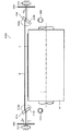
図3、図4は、それぞれ用紙浮き検出装置の第1の実施の形態の正面図、平面図である。 3 and 4 are a front view and a plan view, respectively, of the first embodiment of the sheet floating detection device.
同図に示すように、用紙浮き検出装置300は、検出ビーム(レーザ光)Bを出射する投光ユニット310と、投光ユニット310から出射された検出ビームBを受光する受光ユニット312と、投光ユニット310の前段に配置された投光用硝子平行平板314と、投光用硝子平行平板314を回転駆動する投光用モータ316と、投光用硝子平行平板314の始点位置を検出する投光用始点位置検出センサ318とを備えて構成されている。
As shown in the figure, the paper floating
投光ユニット310と受光ユニット312は、用紙Pの浮きを検出する用紙浮き検出手段を構成する。この投光ユニット310と受光ユニット312は、画像記録ドラム41を挟んで互いに対向して配置される(用紙Pの搬送経路を挟んで互いに対向して配置される。)。
The
投光ユニット310は、図示しないブラケットを介して、インクジェット記録装置10の本体フレームに取り付けられている。この投光ユニット310は、投光素子を備えており、この投光素子から受光ユニット312に向けて検出ビームBを出射する。
The
ここで、検出ビームBは、画像記録ドラム41の回転軸Tと平行(=用紙Pの搬送方向と直交)に出射されるとともに、画像記録ドラム41の外周面(搬送面)から所定高さHの位置を通過するように出射される。したがって、投光ユニット310は、この条件を満たすように設置される。
Here, the detection beam B is emitted in parallel with the rotation axis T of the image recording drum 41 (= perpendicular to the conveyance direction of the paper P), and at a predetermined height H from the outer peripheral surface (conveyance surface) of the
システムコントローラ200は、この投光ユニット310の駆動を制御して、検出ビームBの出射を制御する。
The
受光ユニット312は、図示しないブラケットを介して、インクジェット記録装置10の本体フレームに取り付けられている。この受光ユニット312は、受光素子(たとえば、透過型の光電素子)を備えており、この受光素子で投光ユニット310から出射された検出ビームBを受光する。受光素子は、投光ユニット310の投光素子に対向して設けられ、投光素子から画像記録ドラム41の回転軸Tと平行、かつ、画像記録ドラム41の外周面から所定高さHの位置に出射された検出ビームBを受光する。
The
この受光ユニット312による検出ビームBの受光の情報(受光量)は、システムコントローラ200に出力される。システムコントローラ200は、この受光ユニット312による検出ビームBの受光の情報に基づいて、用紙Pの浮きの有無を判定する。具体的には、あらかじめ設定された閾値と受光量とを比較し、受光量が閾値を以下となると、用紙Pによって検出ビームBが遮られたと判定して、用紙Pの浮きが発生したと判定する。
Information (amount of received light) of the detection beam B received by the
投光用硝子平行平板314は、互いに平行な入射面314aと出射面314bを有する矩形状の透明硝子板で構成されている。この投光用硝子平行平板314は、投光ユニット310の前段(投光ユニット310と画像記録ドラム41との間)に配置されており、用紙Pの搬送方向上流側の側面に設けられた回転軸315を中心に回動自在に設けられている。投光用硝子平行平板314は、この回転軸315が、用紙Pの搬送面と平行(ここでは、検出ビームBの通過位置における画像記録ドラム41の接線の方向と平行)に配置されるとともに、投光ユニット310から出射される検出ビームBに対して直交するように配置される。また、投光ユニット310から出射された検出ビームBが、その入射面314aのほぼ中央に入射するように配置される。
The light projecting glass
投光ユニット310から出射された検出ビームBは、この投光用硝子平行平板314を通過して、受光ユニット312に受光される。
The detection beam B emitted from the
ここで、この投光用硝子平行平板314に入射する検出ビームBは、投光用硝子平行平板314の入射面314aが、検出ビームBに対して直交しているときは、そのまま直進して出射面314bから出射される。一方、投光用硝子平行平板314の入射面314aが、検出ビームBに対して傾斜しているときは、屈折により光軸が上方又は下方にシフトして(屈折率の分だけシフトする)、出射面314bから出射される。
Here, when the
すなわち、この投光用硝子平行平板314の傾斜角度を変えることにより、画像記録ドラム上を通過する検出ビームBの高さhを変えることができる。そして、この投光用硝子平行平板314の傾斜角度は、投光用硝子平行平板314を回動させることにより変更することができる。
That is, the height h of the detection beam B passing on the image recording drum can be changed by changing the inclination angle of the light projecting glass
図5は、投光用硝子平行平板314の回動角度(傾斜角度)と検出ビームの高さ方向の変位量Xとの関係を示すグラフである。
FIG. 5 is a graph showing the relationship between the rotation angle (tilt angle) of the light projecting glass
同図は、検出ビームBに対して直交する姿勢を0°とし、反時計回りの方向の回動角度をプラス(+)、時計回りの方向の回動角度をマイナス(−)としている。 In the figure, the posture orthogonal to the detection beam B is 0 °, the rotation angle in the counterclockwise direction is plus (+), and the rotation angle in the clockwise direction is minus (−).
同図に示すように、投光用硝子平行平板314の回動角度(傾斜角度)に応じて、検出ビームBの位置が上下に変位する。
As shown in the figure, the position of the detection beam B is displaced up and down in accordance with the rotation angle (tilt angle) of the light projecting glass
したがって、図6に示すように、投光用硝子平行平板314の回動角度(傾斜角度)θを調整することにより、画像記録ドラム41の上を通過する検出ビームBの高さh(=出射面314bから出射される検出ビームBの位置)を調整することができる。そして、この高さ調整は、図5に示すように、微小調整することができるので(分解能が高いので)、高精度な高さ調整を行うことができる。
Therefore, as shown in FIG. 6, by adjusting the rotation angle (tilt angle) θ of the light projecting glass
投光用モータ316は、この投光用硝子平行平板314を回転駆動する。この投光用モータ316は、たとえば、正・逆回転可能なパルスモータで構成され、図示しないブラケットを介して、インクジェット記録装置10の本体フレームに取り付けられている。投光用硝子平行平板314は、この投光用モータ316の出力軸に取り付けられて、所定位置に配置されている。したがって、この投光用モータ316を駆動することにより、投光用硝子平行平板314を回動(正・逆回転)させることができる。
The
システムコントローラ200は、この投光用モータ316の駆動を制御して、投光用硝子平行平板314の回動角度(傾斜角度)を制御し、検出ビームBの高さhを制御する。
The
投光用始点位置検出センサ318は、投光用硝子平行平板314が始点位置に位置したことを検出する。すなわち、投光用硝子平行平板314の傾斜角度が0°であること(投光ユニット310から出射される検出ビームBに対して投光用硝子平行平板314の入射面314aが傾斜していないこと)を検出する。この投光用始点位置検出センサ318は、たとえば、近接センサ(磁気センサ等)で構成され、傾斜角度が0°のときの投光用硝子平行平板314の真下に設置される。投光用硝子平行平板314の下面部には、図示しない被検出子が取り付けられており、この被検出子を投光用始点位置検出センサ318で検出することにより、投光用硝子平行平板314の傾斜角度が0°であることを検出する。この投光用始点位置検出センサ318の出力は、システムコントローラ200に出力され、システムコントローラ200は、この投光用始点位置検出センサ318の出力に基づいて、投光用硝子平行平板314の傾斜角度が0°であることを検出する。すなわち、始点位置に位置したことを検出する。
The light projection start point
なお、投光用始点位置検出センサ318の構成は、これに限定されるものではなく、他の構成を採用することもできる。また、上記の例では、近接センサを用いて非接触で検出する構成としているが、接触式のセンサを用いて検出する構成とすることもできる。
The configuration of the light projection start point
[作用]
次に、上記のように構成された本実施の形態の用紙浮き検出装置300の作用について説明する。
[Action]
Next, the operation of the sheet floating
用紙Pの浮き検出は、用紙Pの搬送面(=本実施の形態では画像記録ドラム41の外周面)から所定高さの位置に検出ビームBを投光し、用紙Pによる遮光の有無を検出することにより行われる。そして、用紙Pによる遮光の有無は、受光ユニット312による検出ビームBの受光の有無によって行われる。すなわち、用紙Pによって検出ビームBが遮光されると、受光ユニット312で検出ビームBが受光されなくなるので、これをもって用紙Pの浮きが生じていることを検出する。
The floating detection of the paper P is performed by projecting the detection beam B at a predetermined height from the conveyance surface of the paper P (= the outer peripheral surface of the
まず、用紙Pの浮きの検出高さh0の設定を行う。用紙Pの浮きの検出高さh0は、用紙Pの厚さtに所定の浮きの許容値α(たとえば、公差割付分)を加算した値(t+α)に設定する。 First, the detection height h0 of the floating of the paper P is set. The detected height h0 of the floating of the paper P is set to a value (t + α) obtained by adding a predetermined floating tolerance α (for example, a tolerance allocation) to the thickness t of the paper P.
この用紙Pの浮きの検出高さh0の設定は、投光用硝子平行平板314を透過した検出ビーム(画像記録ドラム41の上を通過する検出ビーム)Bの高さを搬送面(画像記録ドラム41の外周面)からh0(=t+α)の高さの位置に設定することにより行われる。
The detection height h0 of the floating of the paper P is set by setting the height of the detection beam (detection beam passing over the image recording drum 41) B transmitted through the light projecting glass
図7は、用紙の浮きの検出高さの設定手順を示すフローチャートである。 FIG. 7 is a flowchart showing a procedure for setting the detected height of the sheet floating.
まず、システムコントローラ200は、投光用硝子平行平板314を始点位置に位置させる。
First, the
この処理は、投光用モータ316を駆動し、投光用硝子平行平板314を一方向(時計回りの方向:CW)に回転させ、投光用始点位置検出センサ318で投光用硝子平行平板314が始点位置に位置したことを検出することにより行われる。
In this process, the
したがって、まず、システムコントローラ200は、投光用モータ316を駆動し、投光用硝子平行平板314を時計回り(CW)に回転させる(ステップS10)。システムコントローラ200は、投光用始点位置検出センサ318の出力に基づいて、投光用硝子平行平板314が始点位置に到達したか否か判定する(ステップS11)。そして、到達したと判定すると、投光用モータ316の駆動を停止し、投光用硝子平行平板314の回転を停止させる(ステップS12)。これにより、投光用硝子平行平板314が始点位置に位置する。
Therefore, first, the
次に、システムコントローラ200は、投光ユニット310から検出ビームBを出射させる(ステップS13)。投光ユニット310から出射された検出ビームBは、搬送面から所定高さHの位置を通過して、受光ユニット312で受光される。この状態でシステムコントローラ200は、搬送面を検出する処理、すなわち、検出ビームBを基準位置に位置させる処理を実行する。
Next, the
まず、投光用モータ316を駆動し、投光用硝子平行平板314を時計回り(CW)に回転(検出ビームBが搬送面に近づく方向に回転)させる(ステップS14)。これにより、検出ビームBの高さが徐々に低下し、ある点で受光ユニット312で受光されなくなる。システムコントローラ200は、受光ユニット312からの出力に基づいて、搬送面が検出されたか否かを判定し、検出ビームBが基準位置に位置したか否かを判定する(ステップS15)。すなわち、検出ビームBが、搬送面の高さに到達すると、検出ビームBは搬送面で遮光(本実施の形態では画像記録ドラム41で遮光)されるので、システムコントローラ200は、受光ユニット312での検出ビームBの受光の有無を判定して、検出ビームBが基準位置(搬送面の位置)に位置したか否かを判定する。そして、検出ビームBが基準位置に位置したと判定すると、投光用硝子平行平板314の回転を停止する(ステップS16)。これにより、検出ビームBが搬送面上に位置する。
First, the
次に、システムコントローラ200は、基準位置(搬送面の位置)から検出高さh0の位置に検出ビームBを位置させる。この処理は、投光用モータ316を駆動し、投光用硝子平行平板314を反時計回り(CCW)に規定量回転(検出ビームBが搬送面から離れる方向に規定量回転)させることにより行われる(ステップS17)。すなわち、投光用硝子平行平板314の回転量と検出ビームBの変位量は既知なので(図5参照)、検出ビームBが、搬送面から検出高さh0の位置に位置する分だけ投光用硝子平行平板314を回転(反時計周りに回転)させる。これにより、検出ビームBが、搬送面から検出高さh0の位置に位置する。
Next, the
以上一連の工程で用紙Pの浮きの検出高さh0の設定が完了する。この後、検出が可能になる。 The setting of the detection height h0 of the floating of the paper P is completed by the series of steps described above. After this, detection becomes possible.
上記のように、用紙Pの浮きの検出は、受光ユニット312での検出ビームBの受光の有無によって行われる。すなわち、用紙Pに浮きが生じると、浮いた用紙Pによって検出ビームBが遮光されるので、受光ユニット312で検出ビームBが受光されなくなる(受光量が閾値以下となる)。システムコントローラ200は、この受光ユニット312で検出ビームBが受光されなくなったことをもって、用紙Pの浮きが発生したものと判定し、所定の警告動作(パトランプの点灯、スピーカから警告音の発生等)を実行する。また、これと同時に用紙Pの搬送を停止する。
As described above, the detection of the floating of the paper P is performed based on whether or not the detection beam B is received by the
このように、本実施の形態の用紙浮き検出装置300では、投光用硝子平行平板314を回動させることにより、検出ビームBの高さを変えることができる。これにより、簡単に用紙Pの浮きの検出高さh0を変えることができる。
As described above, in the sheet floating
また、投光用硝子平行平板314を回転させ、屈折率分だけ変位させる構成のため、高分解能の高さ調整を行うことができ、高精度な高さ設定を行うことができる。これにより、高精度な浮き検出を行うことができる。
Further, since the projection glass
さらに、検出高さh0を設定する際、搬送面を検出して、高さ調整を行うことができるので、検出高さh0を高精度に設定することができる。また、経時変化に強く、安定した検出を行うことができる。 Furthermore, when the detection height h0 is set, the conveyance surface can be detected and the height can be adjusted, so that the detection height h0 can be set with high accuracy. In addition, it is resistant to changes over time and can perform stable detection.
なお、上記の例では、用紙Pの浮きの検出高さh0を設定する際、基準位置を検出する処理を1回だけ実施しているが、複数回繰り返して実施することが好ましい。すなわち、上記ステップS14〜S17の処理を複数回繰り返して実施することが好ましい。これにより、より高精度な高さ設定を行うことができる。 In the above example, when setting the detection height h0 of the floating of the paper P, the process of detecting the reference position is performed only once, but it is preferable to repeat the process a plurality of times. That is, it is preferable to repeat the processes in steps S14 to S17 a plurality of times. Thereby, more accurate height setting can be performed.
<第2の実施の形態>
図8は、用紙浮き検出装置の第2の実施の形態の正面図である。
<Second Embodiment>
FIG. 8 is a front view of the second embodiment of the sheet floating detection device.
同図に示すように、本実施の形態の用紙浮き検出装置300Aには、受光ユニット312の前段(受光ユニット312と画像記録ドラム41の間)に所定の開口を有する受光用アパーチャ320が設置されている。この受光用アパーチャ320は、図示しないブラケットを介して、インクジェット記録装置10の本体フレームに固定されている。
As shown in the figure, in the sheet floating
このような受光用アパーチャ320を受光ユニット312の前段に配置することにより、投光ユニット310と受光ユニット312との間で設置に多少のズレが生じた場合であっても、受光用アパーチャ320で検出ビームBの光軸の位置を決めることができ、ロバストネスに強い構造とすることができる。
By arranging such a
なお、本例では、受光側にのみアパーチャを設置しているが、投光側にも同様にアパーチャを設置することが好ましい(図13参照)。すなわち、投光ユニット310の前段(投光ユニット310と画像記録ドラム41との間)に投光用アパーチャを設置することが好ましい。この場合、受光用アパーチャの開口面積を投光用アパーチャの開口面積よりも小さくすることが好ましい。これにより、反射による回り込み光の影響を極力小さくすることができ、より高精度な検出を行うことができる。
In this example, the aperture is installed only on the light receiving side, but it is preferable to install the aperture on the light projecting side as well (see FIG. 13). That is, it is preferable to install a light projection aperture in front of the light projection unit 310 (between the
<第3の実施の形態>
[構成]
図9、図10は、それぞれ用紙浮き検出装置の第3の実施の形態の正面図、平面図である。
<Third Embodiment>
[Constitution]
9 and 10 are a front view and a plan view, respectively, of the third embodiment of the paper floating detection device.
同図に示すように、本実施の形態の用紙浮き検出装置300Bは、受光側にも硝子平行平板が備えられている。したがって、受光側でも検出ビームBの光軸の位置調整を行うことができる。
As shown in the figure, the paper floating
なお、投光側の構成については、上記第1の実施の形態の構成と同じなので、ここでは受光側の構成についてのみ説明する。 Since the configuration on the light projecting side is the same as that of the first embodiment, only the configuration on the light receiving side will be described here.
図9、図10に示すように、受光ユニット312の前段(受光ユニット312と画像記録ドラム41との間)には、受光用硝子平行平板334と、その受光用硝子平行平板334を回転駆動する受光用モータ336と、受光用硝子平行平板334の始点位置を検出する受光用始点位置検出センサ338とが設けられている。
As shown in FIGS. 9 and 10, the light receiving glass
受光用硝子平行平板334は、投光用硝子平行平板314と同様に互いに平行な入射面334aと出射面334bを有する矩形状の透明硝子板で構成されている。この受光用硝子平行平板334は、受光ユニット312の前段(受光ユニット312と画像記録ドラム41との間)に配置されており、用紙Pの搬送方向上流側の側面に設けられた回転軸335を中心に回動自在に設けられている。受光用硝子平行平板334は、この回転軸335が、用紙Pの搬送面と平行(ここでは、検出ビームBの通過位置における画像記録ドラム41の接線の方向と平行)に配置されるとともに、投光ユニット310から出射される検出ビームBに対して直交するように配置される。また、出射面334bの中心が、受光ユニット312の受光面の中心とほぼ一致するように配置されている。
The light receiving glass
投光用硝子平行平板314を通過した検出ビームBは、この受光用硝子平行平板334を通過して、受光ユニット312に受光される。
The detection beam B that has passed through the light projecting glass
ここで、この受光用硝子平行平板334に入射する検出ビームBは、受光用硝子平行平板334の入射面334aが、検出ビームBに対して直交しているときは、そのまま直進して出射面334bから出射される。一方、受光用硝子平行平板334の入射面334aが、検出ビームBに対して傾斜しているときは、屈折により光軸が上方又は下方にシフトして(屈折率の分だけシフトする)、出射面334bから出射される。
Here, when the
すなわち、この受光用硝子平行平板334の傾斜角度を変えることにより、受光ユニット312で受光される検出ビームBの高さ位置を変えることができる。そして、この受光用硝子平行平板334の傾斜角度は、受光用硝子平行平板334を回動させることにより変更することができる。
That is, the height position of the detection beam B received by the
受光用モータ336は、この受光用硝子平行平板334を回転駆動する。この受光用モータ336は、たとえば、正・逆回転可能なパルスモータで構成され、図示しないブラケットを介して、インクジェット記録装置10の本体フレームに取り付けられている。受光用硝子平行平板334は、この受光用モータ336の出力軸に取り付けられて、所定位置に配置されている。したがって、この受光用モータ336を駆動することにより、受光用硝子平行平板334を回動(正・逆回転)させることができる。
The
システムコントローラ200は、この受光用モータ336の駆動を制御して、受光用硝子平行平板334の回動角度(傾斜角度)を制御し、受光ユニット312に入射する検出ビームBの高さ位置を制御する。
The
受光用始点位置検出センサ338は、受光用硝子平行平板334が始点位置に位置したことを検出する。すなわち、受光用硝子平行平板334の傾斜角度が0°であること(検出ビームBに対して受光用硝子平行平板334の入射面334aが傾斜していないこと)を検出する。この受光用始点位置検出センサ338は、たとえば、近接センサ(磁気センサ等)で構成され、傾斜角度が0°のときの受光用硝子平行平板334の真下に設置される。受光用硝子平行平板334の下面部には、図示しない被検出子が取り付けられており、この被検出子を受光用始点位置検出センサ338で検出することにより、受光用硝子平行平板334の傾斜角度が0°であることを検出する。この受光用始点位置検出センサ338の出力は、システムコントローラ200に出力され、システムコントローラ200は、この受光用始点位置検出センサ338の出力に基づいて、受光用硝子平行平板334の傾斜角度が0°であることを検出する。すなわち、始点位置に位置したことを検出する。
The light receiving start point
なお、受光用始点位置検出センサ338の構成は、これに限定されるものではなく、他の構成を採用することもできる。また、上記の例では、近接センサを用いて非接触で検出する構成としているが、接触式のセンサを用いて検出する構成とすることもできる。
Note that the configuration of the light receiving start
[作用]
次に、上記のように構成された本実施の形態の用紙浮き検出装置300Bの作用について説明する。
[Action]
Next, the operation of the sheet floating
なお、用紙Pの浮きを検出する方法は、上記第1の実施の形態の用紙浮き検出装置300と同じ(用紙Pの浮きによる検出ビームBの遮光の有無を検出する)なので、ここでは用紙Pの浮きの検出高さの設定方法について説明する。
Note that the method of detecting the floating of the paper P is the same as that of the paper floating detecting
上記第1の実施の形態の用紙浮き検出装置300と同様に、用紙Pの浮きの検出高さh0は、用紙Pの厚さtに所定の浮きの許容値α(たとえば、公差割付分)を加算した値(t+α)に設定する。
Similarly to the paper floating
図11は、用紙の浮きの検出高さの設定手順を示すフローチャートである。 FIG. 11 is a flowchart showing a procedure for setting the detected height of the sheet floating.
まず、システムコントローラ200は、投光用硝子平行平板314と受光用硝子平行平板334をそれぞれ始点位置に位置させる。
First, the
まず、システムコントローラ200は、投光用モータ316を駆動し、投光用硝子平行平板314を時計回り(CW)に回転させる(ステップS20)。システムコントローラ200は、投光用始点位置検出センサ318の出力に基づいて、投光用硝子平行平板314が始点位置に到達したか否か判定する(ステップS21)。そして、到達したと判定すると、投光用モータ316の駆動を停止し、投光用硝子平行平板314の回転を停止させる(ステップS22)。これにより、投光用硝子平行平板314が始点位置に位置する。
First, the
次に、システムコントローラ200は、受光用モータ336を駆動し、受光用硝子平行平板334を反時計回り(CCW)に回転させる(ステップS23)。システムコントローラ200は、受光用始点位置検出センサ338の出力に基づいて、受光用硝子平行平板334が始点位置に到達したか否か判定する(ステップS24)。そして、到達したと判定すると、受光用モータ336の駆動を停止し、受光用硝子平行平板334の回転を停止させる(ステップS25)。これにより、受光用硝子平行平板334が始点位置に位置する。
Next, the
次に、システムコントローラ200は、投光ユニット310から検出ビームBを出射させる(ステップS26)。投光ユニット310から出射された検出ビームBは、搬送面から所定高さHの位置を通過して、受光ユニット312で受光される。
Next, the
次に、システムコントローラ200は、投光用モータ316を駆動し、投光用硝子平行平板314を時計回り(CW)に回転(検出ビームBが搬送面に近づく方向に回転)させる(ステップS27)。これにより、検出ビームBの高さが徐々に低下し、ある点で受光ユニット312で受光されなくなる。システムコントローラ200は、受光ユニット312からの出力に基づいて、受光ユニット312で検出ビームBが受光されなくなったか否かを判定する(ステップS28)。そして、受光ユニット312で検出ビームBが受光されなくなったと判定すると、投光用硝子平行平板314の回転を停止する(ステップS29)。
Next, the
次に、システムコントローラ200は、投光用モータ316を駆動し、検出ビームBが受光ユニット312で受光されるように、投光用硝子平行平板314を反時計回り(CCW)に所定量回転(検出ビームBが搬送面から所定距離離れる方向に回転)させる(ステップS30)。これにより、検出ビームBが、受光ユニット312で再度受光される。
Next, the
次に、システムコントローラ200は、受光用モータ336を駆動し、受光用硝子平行平板334を反時計回り(CCW)に回転させる(ステップS31)。これにより、ある点で再び検出ビームBが受光ユニット312で受光されなくなる。システムコントローラ200は、受光ユニット312からの出力に基づいて、検出ビームBの受光の有無を判定する(ステップS32)。そして、受光ユニット312で検出ビームBが受光されなくなったと判定すると、受光用硝子平行平板334の回転を停止する(ステップS33)。
Next, the
システムコントローラ200は、この検出ビームBが受光されなくなった位置を基準位置(搬送面の位置)として、投光用硝子平行平板314を反時計回り(CCW)に規定量回転させるとともに(ステップS34)、受光用硝子平行平板334を時計回り(CW)に規定量回転させ、検出ビームBを所定の検出高さh0の位置に位置させる。
The
以上一連の工程で用紙Pの浮きの検出高さh0の設定が完了する。この後、検出が可能になる。 The setting of the detection height h0 of the floating of the paper P is completed by the series of steps described above. After this, detection becomes possible.
このように、受光側にも硝子平行平板を設置し、検出ビームBの高さ調整を可能とすることにより、より高精度な用紙Pの浮き検出を行うことができる。 In this way, by installing a glass parallel plate on the light receiving side and making it possible to adjust the height of the detection beam B, it is possible to detect the floating of the paper P with higher accuracy.
なお、上記の例では、基準位置を検出する処理を1回だけ実施しているが、複数回繰り返して実施することが好ましい。すなわち、上記ステップS27〜S35の処理を複数回繰り返して実施することが好ましい。これにより、より高精度な高さ設定を行うことができる。 In the above example, the process of detecting the reference position is performed only once, but it is preferable to repeat the process a plurality of times. That is, it is preferable to repeat the processes of steps S27 to S35 a plurality of times. Thereby, more accurate height setting can be performed.
<第4の実施の形態>
図12は、用紙浮き検出装置の第4の実施の形態の正面図である。
<Fourth embodiment>
FIG. 12 is a front view of the fourth embodiment of the sheet floating detection device.
同図に示すように、本実施の形態の用紙浮き検出装置300Cは、上記第3の実施の形態の用紙浮き検出装置300Bにおいて、受光ユニット312の前段(受光ユニット312と受光用硝子平行平板334との間)に受光用アパーチャ320を設置したものである。この受光用アパーチャ320は、図示しないブラケットを介して、インクジェット記録装置10の本体フレームに固定されている。
As shown in the figure, the paper floating
このような受光用アパーチャ320を受光ユニット312の前段に配置することにより、投光ユニット310と受光ユニット312との間で設置に多少のズレが生じた場合であっても、受光用アパーチャ320で検出ビームBの光軸の位置を決めることができ、ロバストネスに強い構造とすることができる。
By arranging such a
なお、本例では、受光側にのみアパーチャを設置しているが、投光側にも同様にアパーチャを設置することが好ましい。すなわち、図13に示すように、投光ユニット310の前段(投光ユニット310と画像記録ドラム41との間)に投光用アパーチャ322を設置することが好ましい。この場合、受光用アパーチャ320の開口面積S2を投光用アパーチャ322の開口面積S1よりも小さくすることが好ましい。これにより、反射による回り込み光の影響を極力小さくすることができ、より高精度な検出を行うことができる。
In this example, the aperture is installed only on the light receiving side, but it is preferable to install the aperture on the light projecting side as well. That is, as shown in FIG. 13, it is preferable to install a
<第5の実施の形態>
図14は、用紙浮き検出装置の第5の実施の形態の平面図である。
<Fifth embodiment>
FIG. 14 is a plan view of a fifth embodiment of the paper floating detection apparatus.
同図に示すように、本実施の形態の用紙浮き検出装置300Dは、検出ビームBが、用紙Pの搬送方向と直交する方向(画像記録ドラム41の軸方向)に対して所定角度傾斜(0.3°〜2°傾斜)して投光される。
As shown in the figure, in the sheet floating
このように、検出ビームBを用紙Pの搬送方向と直交する方向に対して所定角度傾斜させることにより、用紙Pの搬送方向と直交する方向の浮きも精度よく検出することができるようになる。 In this way, by tilting the detection beam B by a predetermined angle with respect to the direction orthogonal to the conveyance direction of the paper P, the floating in the direction orthogonal to the conveyance direction of the paper P can be accurately detected.
なお、このように本実施の形態の用紙浮き検出装置300Dでは、検出ビームBを用紙Pの搬送方向と直交する方向に対して所定角度傾斜させるため、投光ユニット及び受光ユニット等が、用紙Pの搬送方向と直交する方向に対して所定角度傾けられて設置される。
As described above, in the paper floating
なお、本例では、上記第3の実施の形態の用紙浮き検出装置300Bの構成で検出ビームBを傾ける構成としたが、他の実施の形態の用紙浮き検出装置においても、検出ビームBを用紙Pの搬送方向と直交する方向に所定角度傾ける構成とすることができる。そして、同様の効果を奏することができる。
In this example, the detection beam B is tilted in the configuration of the paper floating
<第6の実施の形態>
上記のように、本実施の形態の用紙浮き検出装置では、用紙Pの浮きの検出の高さ設定を行う際、基準位置(搬送面の位置)を検出し、検出した基準位置から所望の高さ位置に検出ビームBの高さを変位させて、用紙Pの浮きの検出高さの設定を行うようにしている。そして、基準位置を検出する際、投光用硝子平行平板314(及び受光用硝子平行平板334)を所定の始点位置から一方向に回転させて、基準位置の検出を行うようにしている。
<Sixth Embodiment>
As described above, in the paper floating detection device according to the present embodiment, when setting the height of detection of the paper P floating, the reference position (conveyance surface position) is detected, and the desired height is detected from the detected reference position. The height of the detection beam B is displaced to the vertical position, and the detection height of the sheet P is set. When the reference position is detected, the light projecting glass parallel plate 314 (and the light receiving glass parallel plate 334) is rotated in one direction from the predetermined start position to detect the reference position.
ところで、長期間使用していると、組み付け精度等が低下したりして、始点位置から基準位置が検出されるまでの要する投光用硝子平行平板314(及び受光用硝子平行平板334)の回転量(パルス数)が変動する。また、装置に異常が発生している場合にも、同様に始点位置から基準位置が検出されるまでの要する投光用硝子平行平板314(及び受光用硝子平行平板334)の回転量(パルス数)が変動する。 By the way, if it is used for a long time, the assembling accuracy and the like are reduced, and the rotation of the light projecting glass parallel plate 314 (and the light receiving glass parallel plate 334) required until the reference position is detected from the start position. The amount (number of pulses) varies. Further, even when an abnormality occurs in the apparatus, similarly, the rotation amount (number of pulses) of the light projecting glass parallel plate 314 (and the light receiving glass parallel plate 334) required until the reference position is detected from the start position. ) Will fluctuate.
そこで、この始点位置から基準位置が検出されるまで要する投光用硝子平行平板314(及び受光用硝子平行平板334)の回転量(パルス数)を投光用基準回転量(及び受光用基準回転量)として検出し、閾値(あらかじめ設定された基準回転量(基準パルス数))と比較し、投光用基準回転量(又は受光用基準回転量)が閾値を上回っていたら装置異常と判定する構成とする。 Therefore, the rotation amount (pulse number) of the light projecting glass parallel plate 314 (and the light receiving glass parallel plate 334) required until the reference position is detected from the starting point position is set as the light projecting reference rotation amount (and the light receiving reference rotation). ) And is compared with a threshold value (a preset reference rotation amount (reference pulse number)). If the light projection reference rotation amount (or light reception reference rotation amount) exceeds the threshold value, it is determined that the apparatus is abnormal. The configuration.
これにより、早期に装置異常を検出することができ、安定した用紙Pの浮き検出を行うことができる。なお、装置異常と判定した場合、システムコントローラ200は、所要の警告動作を行う。これに応じて、オペレータは、メンテナンスや清掃等を実施する。
Thereby, the apparatus abnormality can be detected at an early stage, and the floating detection of the paper P can be performed stably. When it is determined that the apparatus is abnormal, the
なお、この構成を実施するため、投光用モータ316(及び受光用モータ336)には、回転量を計測する手段(パルスモータの場合は、パルス数をカウントする手段)を備えることが好ましい。システムコントローラ200は、この投光用モータ316(及び受光用モータ336)の回転量を計測する手段の計測結果に基づいて、始点位置から基準位置が検出されるまで要する投光用硝子平行平板314(及び受光用硝子平行平板334)の回転量(パルス数)を検出し、閾値(あらかじめ設定された基準回転量(基準パルス数))と比較し、閾値を上回っていたら装置異常と判定する。
In order to implement this configuration, the light projecting motor 316 (and the light receiving motor 336) preferably includes means for measuring the amount of rotation (in the case of a pulse motor, means for counting the number of pulses). Based on the measurement result of the means for measuring the rotation amount of the light projecting motor 316 (and the light receiving motor 336), the
<第7の実施の形態>
上記実施の形態では、本発明に係る用紙浮き検出装置をインクジェット記録装置10の画像記録部40に組み込み、画像記録ドラム41によって搬送される用紙Pの浮きを検出する構成としている。
<Seventh embodiment>
In the above-described embodiment, the paper floating detection device according to the present invention is incorporated in the
画像記録ドラム41は、熱容量が大きく、その近傍に検出ビームBを飛ばしていると、外部などから違う温度の空気が検出ビームBの光軸を通りすぎた際、検出ビームBの光軸が曲がり、検出できなくなったり、誤検出を生じたりしてしまう。
If the
そこで、インクジェットヘッド44C、44M、44Y、44Kが画像記録ドラム41の上方にセットされていない場合(たとえば、インクジェットヘッド44C、44M、44Y、44Kがメンテナンス部に退避した場合)や、用紙Pが通紙されていない場合(たとえば、インクジェットヘッド44C、44M、44Y、44Kのメンテナンス中)など、用紙Pの浮きの検出が必要ないとき、システムコントローラ200は、用紙Pの浮きの検出高さh0を高くするか、あるいは、用紙Pの浮き検出を停止する。これにより、誤検出等を防止して、安定したインクジェット記録装置の運転が可能になる。
Therefore, when the inkjet heads 44C, 44M, 44Y, and 44K are not set above the image recording drum 41 (for example, when the inkjet heads 44C, 44M, 44Y, and 44K are retracted to the maintenance unit), the paper P is not passed. When it is not necessary to detect the floating of the paper P, such as when the ink jet heads 44C, 44M, 44Y, and 44K are under maintenance, the
<その他の実施の形態>
上記一連の実施の形態では、本発明に係る用紙浮き検出装置をインクジェット記録装置に組み込んだ場合を例に説明したが、本発明に係る用紙浮き検出装置の用途は、これに限定されるものではない。他の記録装置にも同様に組み込むことができる。また、記録装置以外にも組み込むことができる。
<Other embodiments>
In the series of embodiments described above, the case where the paper floating detection device according to the present invention is incorporated in an inkjet recording apparatus has been described as an example. However, the application of the paper floating detection device according to the present invention is not limited to this. Absent. It can be similarly incorporated in other recording apparatuses. Also, it can be incorporated in other than the recording device.
また、上記実施の形態では、搬送ドラムによってドラム搬送される用紙の浮きを検出する場合を例に説明したが、本発明の適用は、これに限定されるものではない。他の搬送手段で搬送される場合にも同様に適用することができる。たとえば、搬送ベルトによってベルト搬送される用紙の浮きを検出する場合にも同様に適用することができる。また、用紙を吸着等して保持しながら搬送する場合に限らず、所定の搬送面を滑らせて搬送する場合にも同様に適用することができる。たとえば、プラテン上を搬送される用紙の浮きを検出する場合にも適用することができる。 In the above-described embodiment, the case where the floating of the sheet conveyed by the conveyance drum is detected has been described as an example. However, the application of the present invention is not limited to this. The same can be applied to the case of being transported by other transport means. For example, the present invention can be similarly applied to the case where the floating of the sheet conveyed by the conveyance belt is detected. Further, the present invention is not limited to the case where the sheet is conveyed while being sucked and held, but can be similarly applied to a case where the sheet is conveyed while sliding on a predetermined conveyance surface. For example, the present invention can also be applied to detecting the floating of a sheet conveyed on a platen.
また、上記実施の形態では、投光用の平行平板と受光用の平行平板にガラス製のものを用いているが、平行平板を構成する素材は、これに限定されるものではない。他の素材で構成された平行平板を用いることもできる。 Moreover, in the said embodiment, although the thing made from glass is used for the parallel plate for light projection and the parallel plate for light reception, the raw material which comprises a parallel plate is not limited to this. Parallel flat plates made of other materials can also be used.
10…インクジェット記録装置、20…給紙部、21…給紙装置、22…給紙トレイ、23…渡し胴、30…処理液付与部、31…搬送ドラム(処理液付与ドラム)、32…処理液付与装置、40…画像記録部、41…搬送ドラム(画像記録ドラム)、42…用紙押さえローラ、44C、44M、44Y、44K…インクジェットヘッド、50…インク乾燥部、51…搬送ドラム(インク乾燥ドラム)、52…インク乾燥装置、60…定着部、61…搬送ドラム(定着ドラム)、62、63…ヒートローラ、64…インラインセンサ、70…回収部、71…スタッカ、72…排紙コンベア、80…渡し胴、81…渡し胴本体、83…ガイド板、84…ドライヤ、90…渡し胴、91…渡し胴本体、93…ガイド板、94…ドライヤ、100…渡し胴、101…渡し胴本体、103…ガイド板、104…ドライヤ、200…システムコントローラ、201…通信部、202…画像メモリ、203…搬送制御部、204…給紙制御部、205…処理液付与制御部、206…画像記録制御部、207…インク乾燥制御部、208…定着制御部、209…回収制御部、201…操作部、211…表示部、212…警告部、300、200A、300B、300C、300D…用紙浮き検出装置、310…投光ユニット、312…受光ユニット、314…投光用硝子平行平板、314a…入射面、314b…出射面、315…回転軸、316…投光用モータ、318…投光用始点位置検出センサ、320…受光用アパーチャ、322…投光用アパーチャ、334…受光用硝子平行平板、334a…入射面、334b…出射面、335…回転軸、336…受光用モータ、338…受光用始点位置検出センサ、P…用紙、B…検出ビーム、G…グリッパ
DESCRIPTION OF
Claims (15)
前記搬送経路を挟んで互いに対向して配置される投光部と受光部とを有し、前記搬送面から所定高さの位置に前記搬送面と平行な検出ビームを前記投光部から前記受光部に向けて出射し、前記受光部での前記検出ビームの受光の有無を検出して、前記用紙の浮きの有無を検出する用紙浮き検出手段と、
前記投光部から出射された前記検出ビームが透過するように前記投光部の前段に配置されるとともに、前記搬送面と平行し且つ前記検出ビームと直交する軸の周りを回動自在に設けられ、回動することにより内部を透過して出射する前記検出ビームの高さを可変させる投光用平行平板と、
前記投光用平行平板を回転駆動する投光用平行平板回転駆動手段と、
を備えたことを特徴とする用紙浮き検出装置。 In a paper float detection device that detects the float of a paper transported along a predetermined transport path on a predetermined transport surface,
A light projecting unit and a light receiving unit disposed opposite to each other across the transport path, and receiving a detection beam parallel to the transport surface at a predetermined height from the transport surface from the light projecting unit; A sheet floating detection means for detecting whether or not the sheet floats by detecting the presence or absence of the detection beam at the light receiving unit.
It is arranged in front of the light projecting unit so that the detection beam emitted from the light projecting unit is transmitted, and is rotatably provided around an axis parallel to the transport surface and orthogonal to the detection beam. A projecting parallel plate for varying the height of the detection beam that passes through and is emitted by rotating;
A projecting parallel plate rotation driving means for rotating the projecting parallel plate;
A sheet floating detection device comprising:
前記受光用平行平板を回転駆動する受光用平行平板回転駆動手段と、
を備えたことを特徴とする請求項1に記載の用紙浮き検出装置。 It is arranged in front of the light receiving unit so that the detection beam that has passed through the projecting parallel plate is transmitted, and is provided rotatably around an axis that is parallel to the transport surface and orthogonal to the detection beam. And a light receiving parallel plate that varies the height of the detection beam that passes through and exits by rotating,
A light receiving parallel plate rotation driving means for rotating the light receiving parallel plate;
The sheet floating detection device according to claim 1, further comprising:
該検出高さ調整手段は、
前記受光部で前記検出ビームが受光されている状態で前記投光用平行平板を第1の方向に回転させて、前記検出ビームを前記搬送面に近づく方向に移動させ、前記検出ビームが前記搬送面で遮光されることによって、前記受光部で前記検出ビームが受光されなくなったら前記投光用平行平板の回転を停止し、次いで、前記検出ビームが前記受光部で受光されるように、前記第1の方向とは逆方向の第2の方向に前記投光用平行平板を回転させて、前記搬送面から所定距離離れた位置に前記検出ビームを移動させ、次いで、前記受光用平行平板を前記第2の方向に回転させ、前記受光部で前記検出ビームが受光されなくなったら前記受光用平行平板の回転を停止し、当該位置を基準位置として、前記検出ビームが所定の検出高さの位置に位置するように、前記基準位置から前記受光用平行平板を前記第1の方向に回転させるとともに、前記投光用平行平板を前記第2の方向に回転させる動作を行って、前記検出ビームの高さを調整することを特徴とする請求項2〜5のいずれか一項に記載の用紙浮き検出装置。 A detection height for adjusting the height of the detection beam by controlling the driving of the light-projecting parallel plate rotation driving means and the light-receiving parallel plate rotation driving means based on the detection result of the sheet floating detection means. Adjusting means,
The detected height adjusting means includes
The projection parallel plate is rotated in a first direction while the detection beam is received by the light receiving unit, and the detection beam is moved in a direction approaching the transport surface, so that the detection beam is transported. by being shielded by a surface, said detection beam by the light receiving unit stops the rotation of the parallel plate for the light projection once it is no longer received, then, as the detection beam is received by the light receiving portion, said first the first direction of the light projecting parallel plate in a second direction reverse to rotation, moving the detection beam at a predetermined distance from said conveying surface, then the light receiving parallel plate When the detection beam is no longer received by the light receiving unit after rotating in the second direction, the rotation of the light receiving parallel plate is stopped, and the detection beam is positioned at a predetermined detection height with the position as a reference position. Located in As such, causes the rotation of the light receiving parallel plate in the first direction from the reference position by performing an operation to rotate the parallel-plate for the light projection in the second direction, the high of the detection beam The sheet floating detection device according to any one of claims 2 to 5, wherein the height of the sheet is adjusted.
前記投光用始点位置から前記基準位置までの前記投光用平行平板の回転量を投光用基準回転量として検出する投光用基準回転量検出手段と、
前記投光用基準回転量検出手段で検出された投光用基準回転量を閾値と比較し、装置異常の有無を判定する異常判定手段と、
を備えたことを特徴とする請求項6又は7に記載の用紙浮き検出装置。 The detection height adjusting means starts the operation from a predetermined light projection start position,
A light projection reference rotation amount detection means for detecting a rotation amount of the light projection parallel plate from the light projection start point position to the reference position as a light projection reference rotation amount;
An abnormality determination unit that compares the reference rotation amount for light projection detected by the light projection reference rotation amount detection unit with a threshold value and determines whether or not there is a device abnormality;
The sheet floating detection device according to claim 6 or 7, further comprising:
前記投光用始点位置から前記基準位置までの前記投光用平行平板の回転量を投光用基準回転量として検出する投光用基準回転量検出手段と、
前記受光用始点位置から前記基準位置までの受光用平行平板の回転量を受光用基準回転量として検出する受光用基準回転量検出手段と、
前記投光用基準回転量検出手段で検出された投光用基準回転量を閾値と比較するとともに、前記受光用基準回転量検出手段で検出された受光用基準回転量を閾値と比較し、装置異常の有無を判定する異常判定手段と、
を備えたことを特徴とする請求項7に記載の用紙浮き検出装置。 The detection height adjusting means starts the operation from a predetermined light projecting start position and light receiving start position,
A light projection reference rotation amount detection means for detecting a rotation amount of the light projection parallel plate from the light projection start point position to the reference position as a light projection reference rotation amount;
A light receiving reference rotation amount detecting means for detecting a rotation amount of the light receiving parallel plate from the light receiving start position to the reference position as a light receiving reference rotation amount;
Comparing the light projection reference rotation amount detected by the light projection reference rotation amount detection means with a threshold value, and comparing the light reception reference rotation amount detected by the light reception reference rotation amount detection means with a threshold value; An abnormality determination means for determining the presence or absence of abnormality;
The sheet floating detection device according to claim 7, further comprising:
前記搬送手段によって搬送される用紙の記録面にインクを打滴して画像を描画するインクジェットヘッドと、
前記インクジェットヘッドの上流側に設置され、前記搬送手段の搬送面からの前記用紙の浮きを検出する請求項1〜11のいずれか一項に記載の用紙浮き検出装置と、
前記用紙浮き検出装置の検出結果に基づいて、前記用紙の搬送異常を判定する搬送異常判定手段と、
を備えたことを特徴とするインクジェット記録装置。 Conveying means for conveying paper;
An ink jet head for drawing an image by ejecting ink onto a recording surface of a sheet conveyed by the conveying means;
The paper floating detection device according to any one of claims 1 to 11, wherein the paper floating detection device is installed upstream of the inkjet head and detects the paper floating from a conveyance surface of the conveyance unit.
A conveyance abnormality determining means for determining a conveyance abnormality of the sheet based on a detection result of the sheet floating detection device;
An ink jet recording apparatus comprising:
Priority Applications (2)
| Application Number | Priority Date | Filing Date | Title |
|---|---|---|---|
| JP2010060918A JP5406086B2 (en) | 2010-03-17 | 2010-03-17 | Paper float detection device and ink jet recording device |
| US13/049,031 US8622495B2 (en) | 2010-03-17 | 2011-03-16 | Paper floating detection apparatus and inkjet recording apparatus |
Applications Claiming Priority (1)
| Application Number | Priority Date | Filing Date | Title |
|---|---|---|---|
| JP2010060918A JP5406086B2 (en) | 2010-03-17 | 2010-03-17 | Paper float detection device and ink jet recording device |
Publications (3)
| Publication Number | Publication Date |
|---|---|
| JP2011195221A JP2011195221A (en) | 2011-10-06 |
| JP2011195221A5 JP2011195221A5 (en) | 2012-08-02 |
| JP5406086B2 true JP5406086B2 (en) | 2014-02-05 |
Family
ID=44646882
Family Applications (1)
| Application Number | Title | Priority Date | Filing Date |
|---|---|---|---|
| JP2010060918A Active JP5406086B2 (en) | 2010-03-17 | 2010-03-17 | Paper float detection device and ink jet recording device |
Country Status (2)
| Country | Link |
|---|---|
| US (1) | US8622495B2 (en) |
| JP (1) | JP5406086B2 (en) |
Families Citing this family (12)
| Publication number | Priority date | Publication date | Assignee | Title |
|---|---|---|---|---|
| JP5489926B2 (en) * | 2010-08-31 | 2014-05-14 | 富士フイルム株式会社 | Recording medium floating detection apparatus and inkjet recording apparatus |
| JP5608583B2 (en) * | 2011-02-09 | 2014-10-15 | 富士フイルム株式会社 | Table creation method, recording medium floating detection device, and image recording device |
| JP5456087B2 (en) * | 2012-02-20 | 2014-03-26 | 富士フイルム株式会社 | Image forming apparatus |
| JP5972192B2 (en) * | 2013-02-28 | 2016-08-17 | 富士フイルム株式会社 | Recording medium floating detection apparatus and inkjet recording apparatus |
| JP6076848B2 (en) * | 2013-07-02 | 2017-02-08 | 富士フイルム株式会社 | Inkjet recording device |
| JP6337538B2 (en) * | 2014-03-18 | 2018-06-06 | セイコーエプソン株式会社 | Image recording apparatus, calibration method, and image recording method |
| CN107073979B (en) * | 2014-10-16 | 2019-03-15 | 小森公司 | Digital printer |
| CN106794703B (en) | 2014-10-16 | 2020-03-06 | 小森公司 | Digital printer |
| JP2017018588A (en) * | 2015-07-09 | 2017-01-26 | 船井電機株式会社 | Injection device |
| US10124969B2 (en) | 2016-06-08 | 2018-11-13 | Canon Finetech Nisca Inc. | Conveyance apparatus, image reading apparatus, and image forming apparatus |
| JP2017222515A (en) * | 2016-06-08 | 2017-12-21 | キヤノンファインテックニスカ株式会社 | Transportation device, image reading device, image formation device and control method |
| JP6886049B2 (en) * | 2018-01-19 | 2021-06-16 | 富士フイルム株式会社 | Transmission type detection device, medium floating detection device, and image forming device |
Family Cites Families (10)
| Publication number | Priority date | Publication date | Assignee | Title |
|---|---|---|---|---|
| DE19906343B4 (en) | 1998-03-11 | 2010-11-11 | Heidelberger Druckmaschinen Ag | Device for conveying a printed product by a printing machine |
| JP2003081527A (en) * | 2001-09-10 | 2003-03-19 | Fuji Photo Film Co Ltd | Roll winding displacement measuring device and roll winding device |
| JP4089277B2 (en) * | 2002-04-23 | 2008-05-28 | ブラザー工業株式会社 | Printhead interference detection device for ink jet printer |
| JP2004004191A (en) * | 2002-05-30 | 2004-01-08 | Ricoh Co Ltd | Optical scanner |
| JP2004299155A (en) * | 2003-03-31 | 2004-10-28 | Mimaki Engineering Co Ltd | Ink jet head protective mechanism of ink jet printer |
| JP4670558B2 (en) * | 2005-09-13 | 2011-04-13 | 富士ゼロックス株式会社 | Droplet discharge device |
| JP2007098650A (en) * | 2005-09-30 | 2007-04-19 | Kubota Matsushitadenko Exterior Works Ltd | Coating apparatus |
| JP4222522B2 (en) | 2006-11-22 | 2009-02-12 | 東京エレクトロン株式会社 | Optical foreign matter detection device and treatment liquid coating device equipped with the same |
| JP2010076872A (en) | 2008-09-25 | 2010-04-08 | Fujifilm Corp | Image forming device and method of detecting floating of recording medium |
| JP5489926B2 (en) * | 2010-08-31 | 2014-05-14 | 富士フイルム株式会社 | Recording medium floating detection apparatus and inkjet recording apparatus |
-
2010
- 2010-03-17 JP JP2010060918A patent/JP5406086B2/en active Active
-
2011
- 2011-03-16 US US13/049,031 patent/US8622495B2/en active Active
Also Published As
| Publication number | Publication date |
|---|---|
| US8622495B2 (en) | 2014-01-07 |
| JP2011195221A (en) | 2011-10-06 |
| US20110227985A1 (en) | 2011-09-22 |
Similar Documents
| Publication | Publication Date | Title |
|---|---|---|
| JP5406086B2 (en) | Paper float detection device and ink jet recording device | |
| JP6076848B2 (en) | Inkjet recording device | |
| JP5489926B2 (en) | Recording medium floating detection apparatus and inkjet recording apparatus | |
| JP5608583B2 (en) | Table creation method, recording medium floating detection device, and image recording device | |
| US9010923B2 (en) | Sheet conveying device and ink jet recording apparatus | |
| JP5480854B2 (en) | Paper transport apparatus and ink jet recording apparatus | |
| US9718289B2 (en) | Inkjet recording apparatus | |
| US8632156B2 (en) | Paper floating detection apparatus, paper conveyance apparatus and image recording apparatus | |
| JP2011161822A (en) | Device and method for inkjet printing | |
| US9883069B2 (en) | Image reading device and printing apparatus | |
| US10391794B2 (en) | Defect detection for print media | |
| JP5972192B2 (en) | Recording medium floating detection apparatus and inkjet recording apparatus | |
| EP3523634A1 (en) | Defect detection for print media | |
| JP2012096863A (en) | Inkjet recording apparatus | |
| JP7289281B2 (en) | Paper floating detection device and program, conveying device, printing device | |
| JP7080160B2 (en) | Belt drive device and image forming device | |
| JP2011195296A (en) | Paper floating detection device, paper conveying device, and image recording device | |
| US10773518B2 (en) | Liquid ejection apparatus | |
| JP2017530071A (en) | Printing system and method for transporting print media in a printing system |
Legal Events
| Date | Code | Title | Description |
|---|---|---|---|
| A521 | Request for written amendment filed |
Free format text: JAPANESE INTERMEDIATE CODE: A523 Effective date: 20120614 |
|
| A621 | Written request for application examination |
Free format text: JAPANESE INTERMEDIATE CODE: A621 Effective date: 20120614 |
|
| A977 | Report on retrieval |
Free format text: JAPANESE INTERMEDIATE CODE: A971007 Effective date: 20130524 |
|
| A131 | Notification of reasons for refusal |
Free format text: JAPANESE INTERMEDIATE CODE: A131 Effective date: 20130529 |
|
| A521 | Request for written amendment filed |
Free format text: JAPANESE INTERMEDIATE CODE: A523 Effective date: 20130724 |
|
| TRDD | Decision of grant or rejection written | ||
| A01 | Written decision to grant a patent or to grant a registration (utility model) |
Free format text: JAPANESE INTERMEDIATE CODE: A01 Effective date: 20131024 |
|
| A61 | First payment of annual fees (during grant procedure) |
Free format text: JAPANESE INTERMEDIATE CODE: A61 Effective date: 20131031 |
|
| R150 | Certificate of patent or registration of utility model |
Ref document number: 5406086 Country of ref document: JP Free format text: JAPANESE INTERMEDIATE CODE: R150 |
|
| R250 | Receipt of annual fees |
Free format text: JAPANESE INTERMEDIATE CODE: R250 |
|
| R250 | Receipt of annual fees |
Free format text: JAPANESE INTERMEDIATE CODE: R250 |
|
| R250 | Receipt of annual fees |
Free format text: JAPANESE INTERMEDIATE CODE: R250 |
|
| R250 | Receipt of annual fees |
Free format text: JAPANESE INTERMEDIATE CODE: R250 |
|
| R250 | Receipt of annual fees |
Free format text: JAPANESE INTERMEDIATE CODE: R250 |
|
| R250 | Receipt of annual fees |
Free format text: JAPANESE INTERMEDIATE CODE: R250 |
|
| R250 | Receipt of annual fees |
Free format text: JAPANESE INTERMEDIATE CODE: R250 |
|
| R250 | Receipt of annual fees |
Free format text: JAPANESE INTERMEDIATE CODE: R250 |