JP5405313B2 - Apparatus and method for separating a composite liquid into at least two components - Google Patents
Apparatus and method for separating a composite liquid into at least two components Download PDFInfo
- Publication number
- JP5405313B2 JP5405313B2 JP2009543034A JP2009543034A JP5405313B2 JP 5405313 B2 JP5405313 B2 JP 5405313B2 JP 2009543034 A JP2009543034 A JP 2009543034A JP 2009543034 A JP2009543034 A JP 2009543034A JP 5405313 B2 JP5405313 B2 JP 5405313B2
- Authority
- JP
- Japan
- Prior art keywords
- bag
- separation
- component
- separation bag
- volume
- Prior art date
- Legal status (The legal status is an assumption and is not a legal conclusion. Google has not performed a legal analysis and makes no representation as to the accuracy of the status listed.)
- Active
Links
Images


Classifications
-
- A—HUMAN NECESSITIES
- A61—MEDICAL OR VETERINARY SCIENCE; HYGIENE
- A61M—DEVICES FOR INTRODUCING MEDIA INTO, OR ONTO, THE BODY; DEVICES FOR TRANSDUCING BODY MEDIA OR FOR TAKING MEDIA FROM THE BODY; DEVICES FOR PRODUCING OR ENDING SLEEP OR STUPOR
- A61M1/00—Suction or pumping devices for medical purposes; Devices for carrying-off, for treatment of, or for carrying-over, body-liquids; Drainage systems
- A61M1/36—Other treatment of blood in a by-pass of the natural circulatory system, e.g. temperature adaptation, irradiation ; Extra-corporeal blood circuits
- A61M1/3693—Other treatment of blood in a by-pass of the natural circulatory system, e.g. temperature adaptation, irradiation ; Extra-corporeal blood circuits using separation based on different densities of components, e.g. centrifuging
-
- A—HUMAN NECESSITIES
- A61—MEDICAL OR VETERINARY SCIENCE; HYGIENE
- A61M—DEVICES FOR INTRODUCING MEDIA INTO, OR ONTO, THE BODY; DEVICES FOR TRANSDUCING BODY MEDIA OR FOR TAKING MEDIA FROM THE BODY; DEVICES FOR PRODUCING OR ENDING SLEEP OR STUPOR
- A61M1/00—Suction or pumping devices for medical purposes; Devices for carrying-off, for treatment of, or for carrying-over, body-liquids; Drainage systems
- A61M1/36—Other treatment of blood in a by-pass of the natural circulatory system, e.g. temperature adaptation, irradiation ; Extra-corporeal blood circuits
- A61M1/3692—Washing or rinsing blood or blood constituents
-
- A—HUMAN NECESSITIES
- A61—MEDICAL OR VETERINARY SCIENCE; HYGIENE
- A61M—DEVICES FOR INTRODUCING MEDIA INTO, OR ONTO, THE BODY; DEVICES FOR TRANSDUCING BODY MEDIA OR FOR TAKING MEDIA FROM THE BODY; DEVICES FOR PRODUCING OR ENDING SLEEP OR STUPOR
- A61M1/00—Suction or pumping devices for medical purposes; Devices for carrying-off, for treatment of, or for carrying-over, body-liquids; Drainage systems
- A61M1/36—Other treatment of blood in a by-pass of the natural circulatory system, e.g. temperature adaptation, irradiation ; Extra-corporeal blood circuits
- A61M1/3693—Other treatment of blood in a by-pass of the natural circulatory system, e.g. temperature adaptation, irradiation ; Extra-corporeal blood circuits using separation based on different densities of components, e.g. centrifuging
- A61M1/3695—Other treatment of blood in a by-pass of the natural circulatory system, e.g. temperature adaptation, irradiation ; Extra-corporeal blood circuits using separation based on different densities of components, e.g. centrifuging with sedimentation by gravity
-
- A—HUMAN NECESSITIES
- A61—MEDICAL OR VETERINARY SCIENCE; HYGIENE
- A61M—DEVICES FOR INTRODUCING MEDIA INTO, OR ONTO, THE BODY; DEVICES FOR TRANSDUCING BODY MEDIA OR FOR TAKING MEDIA FROM THE BODY; DEVICES FOR PRODUCING OR ENDING SLEEP OR STUPOR
- A61M1/00—Suction or pumping devices for medical purposes; Devices for carrying-off, for treatment of, or for carrying-over, body-liquids; Drainage systems
- A61M1/36—Other treatment of blood in a by-pass of the natural circulatory system, e.g. temperature adaptation, irradiation ; Extra-corporeal blood circuits
- A61M1/3693—Other treatment of blood in a by-pass of the natural circulatory system, e.g. temperature adaptation, irradiation ; Extra-corporeal blood circuits using separation based on different densities of components, e.g. centrifuging
- A61M1/3698—Expressing processed fluid out from the turning rotor using another fluid compressing the treatment chamber; Variable volume rotors
-
- C—CHEMISTRY; METALLURGY
- C12—BIOCHEMISTRY; BEER; SPIRITS; WINE; VINEGAR; MICROBIOLOGY; ENZYMOLOGY; MUTATION OR GENETIC ENGINEERING
- C12M—APPARATUS FOR ENZYMOLOGY OR MICROBIOLOGY; APPARATUS FOR CULTURING MICROORGANISMS FOR PRODUCING BIOMASS, FOR GROWING CELLS OR FOR OBTAINING FERMENTATION OR METABOLIC PRODUCTS, i.e. BIOREACTORS OR FERMENTERS
- C12M47/00—Means for after-treatment of the produced biomass or of the fermentation or metabolic products, e.g. storage of biomass
- C12M47/02—Separating microorganisms from the culture medium; Concentration of biomass
Description
本願は、一定容量の複合液体を少なくとも2つの成分に分離するための機器および方法に関する。 The present application relates to an apparatus and method for separating a volume of a composite liquid into at least two components.
(関連出願に対する相互参照)
本願は、2006年12月20日に出願された米国仮出願第60/870860号の利益を主張する。
(Cross-reference to related applications)
This application claims the benefit of US Provisional Application No. 60 / 870,860, filed December 20, 2006.
本発明の機器および方法は、水性成分および1つ以上の細胞成分を含有する生体液を分離するのに特に適切である。たとえば、本発明は、一定容量の全血から、血漿成分および赤血球成分の抽出、血小板濃厚血漿成分および赤血球成分の抽出、または、血漿成分、血小板/単核球成分および赤血球成分の抽出を含む使用の可能性がある。 The devices and methods of the present invention are particularly suitable for separating biological fluids containing an aqueous component and one or more cellular components. For example, the present invention involves the extraction of plasma and erythrocyte components, platelet-rich plasma and erythrocyte components, or plasma, platelet / mononuclear and erythrocyte components from a fixed volume of whole blood There is a possibility.
特許文献1には、様々な分離プロトコルにしたがって、一定容量の全血を少なくとも3つの成分に分離する方法および機器が記載されている。たとえば、1つのプロトコルは、一定容量の全血を、血漿成分、赤血球成分および単核球成分(一定容量の血漿、血小板、単核球および残りの赤血球を含む)に分離することを提供する。この機器は、血漿用のバッグ、単核球成分用のバッグ、および、赤血球成分バッグ用のバッグを含む3つのサテライトバッグに接続されている、環状分離バッグを備えるバッグセットを含む、様々なバッグセットと協働するように適合された遠心分離機を備える。遠心分離機は、分離バッグをスピンして中に収容された全血を遠心分離するためのロータであって、分離バッグを支持するためのターンテーブルと、分離バッグに接続された成分バッグを収容するための中心コンパートメントと、を有するロータと、分離バッグを圧搾して、少なくとも血漿成分を血漿成分バッグ内に移動させ且つ単核球成分を単核球成分バッグ内に移動させる圧搾システムとを含む。
特許文献1によれば、分離バッグに収容される一定容量の全血を少なくとも3つの成分に分離する方法は、分離バッグの中で、血漿を含有する第1の内側層と、血小板を含有する第2の中間層と、リンパ球、単球および顆粒球を含有する第3の中間層と、赤血球を含有する第4の外側層とを分離させ、少なくとも第3の層および第4の層は、部分的にオーバーラップするように、分離バッグを遠心分離することと、分離バッグに接続された血漿成分バッグ内に、第1の層の第1の画分を実質的に含有する血漿成分を移すことと、分離バッグに接続された単核球成分バッグ内に、リンパ球および単球を含有する第3の層の画分を少なくとも含有する単核球成分を移すことと、の各ステップを備える。
According to
この方法は、様々な理由のために輸血可能な赤血球には望ましくない単核球を実質的に含まない赤血球成分を分離することを可能にする。 This method makes it possible to separate red blood cell components that are substantially free of mononuclear cells that are undesirable for transmissible red blood cells for various reasons.
白血球は、望ましくないタンパク質(たとえばプリオン)およびウイルスを含むかもしれない血漿の残り容量内に赤血球が詰められる赤血球成分から少なくとも部分的に除去することが望ましい唯一の汚染物質ではない。 White blood cells are not the only contaminant that it is desirable to at least partially remove from the red blood cell components that are packed with red blood cells in the remaining volume of plasma that may contain unwanted proteins (eg, prions) and viruses.
本発明の1つの目的は、血漿が除去されている輸血可能な赤血球生成物を準備するのを可能にする分離全血用の方法および機器を設計することである。 One object of the present invention is to design a method and apparatus for separated whole blood that allows for the preparation of a transfusion red blood cell product from which plasma has been removed.
本発明によれば、一定容量の全血を少なくとも血漿成分と赤血球成分とに分離するための方法は、一定容量の全血を収容する分離バッグを遠心分離して、分離バッグの中で、少なくとも、血漿を含有する第1の成分と赤血球を含有する第2の成分とに分離することと、分離バッグの遠心分離中に、分離バッグに接続された血漿成分バッグ内に第1の成分を移すことと、分離バッグの遠心分離中に、分離バッグに接続された洗浄液バッグから分離バッグ内に一定容量の洗浄液を移すことと、一定容量の洗浄液を第2の成分と混合することと、分離バッグを遠心分離して、分離バッグの中で、洗浄された赤血球成分と使用済み洗浄液を含有する上清成分とを分離することと、分離バッグの遠心分離中に、分離バッグに接続された廃棄物バッグ内に上清成分を移すことと、を備える。 According to the present invention, a method for separating a constant volume of whole blood into at least a plasma component and a red blood cell component comprises centrifuging a separation bag containing a constant volume of whole blood, and at least in the separation bag, Separating the first component containing plasma and the second component containing red blood cells, and transferring the first component into the plasma component bag connected to the separation bag during centrifugation of the separation bag And, during centrifugation of the separation bag, transferring a fixed volume of cleaning liquid from the cleaning liquid bag connected to the separation bag into the separation bag, mixing the fixed volume of cleaning liquid with the second component, and the separation bag And separating the washed red blood cell component and the supernatant component containing the used washing liquid in the separation bag, and the waste connected to the separation bag during centrifugation of the separation bag In the bag And a transferring the supernatant component.
方法は、分離バッグに接続された全血バッグから分離バッグ内に一定容量の全血を移すことをさらに備えてもよい。また、一定容量の全血は、遠心分離によって、全血バッグから分離バッグ内に移されてもよい。分離バッグは遠心分離されて、分離バッグの中で、血漿を含有する第1の成分と、赤血球を含有する第2の成分と、血小板および単核球を含有する中間成分と、に分離する。 The method may further comprise transferring a volume of whole blood from the whole blood bag connected to the separation bag into the separation bag. A fixed volume of whole blood may also be transferred from the whole blood bag into the separation bag by centrifugation. The separation bag is centrifuged and separated in the separation bag into a first component containing plasma, a second component containing red blood cells, and an intermediate component containing platelets and mononuclear cells.
方法は、分離バッグの遠心分離中に、分離バッグに接続された中間成分バッグ内に中間成分を移すことと、をさらに備える。 The method further comprises transferring the intermediate component into an intermediate component bag connected to the separation bag during centrifugation of the separation bag.
方法は、分離バッグに接続された全血バッグから分離バッグ内に一定容量の全血を移すことと、一定容量の全血が分離バッグ内に移された後に、全血バッグ内に中間成分を移すことと、をさらに備えてもよい。 The method transfers a constant volume of whole blood from a whole blood bag connected to the separation bag into the separation bag and, after the constant volume of whole blood has been transferred into the separation bag, an intermediate component in the whole blood bag. May be further provided.
一定容量の洗浄液は、遠心分離によって分離バッグ内に移される。 A fixed volume of wash solution is transferred into the separation bag by centrifugation.
分離バッグ内に移される一定容量の洗浄液は、実質的に、洗浄液バッグに当初収容された洗浄液の総容量に対応する。 The fixed volume of cleaning liquid transferred into the separation bag substantially corresponds to the total volume of cleaning liquid initially contained in the cleaning liquid bag.
上清成分は、洗浄液が分離バッグ内に移された後に廃棄物バッグとして使用される洗浄液バッグ内に移される。分離バッグ内に移される一定容量の洗浄液は、洗浄液バッグに当初収容された洗浄液の総容量の第1の画分である。 The supernatant component is transferred into a cleaning solution bag that is used as a waste bag after the cleaning solution is transferred into the separation bag. The fixed volume of cleaning liquid transferred into the separation bag is the first fraction of the total volume of cleaning liquid initially contained in the cleaning liquid bag.
方法は、分離バッグに接続された全血バッグから分離バッグ内に一定容量の全血を移すことと、分離バッグから、一定容量の全血が分離バッグ内に移された後に廃棄物バッグとして使用される全血バッグ内に、上清成分を移すことと、をさらに備える。 The method transfers a constant volume of whole blood from a whole blood bag connected to the separation bag into the separation bag and is used as a waste bag after a certain volume of whole blood is transferred from the separation bag into the separation bag. And transferring the supernatant component into the whole blood bag to be added.
方法は、廃棄物バッグ内に上清成分を移した後に、分離バッグの遠心分離中に、洗浄液バッグに当初収容された洗浄液の総容量の第2の画分を、分離バッグ内に移すことと、洗浄液を第2の成分と混合することと、分離バッグを遠心分離して、分離バッグの中で、洗浄された赤血球成分と、使用済み洗浄液を含有する上清成分と、に分離することと、分離バッグの遠心分離中に、廃棄物バッグ内に上清成分を移すことと、をさらに備える。 The method includes transferring a second fraction of the total volume of the cleaning solution originally contained in the cleaning solution bag into the separation bag during centrifugation of the separation bag after transferring the supernatant component into the waste bag. Mixing the washing solution with the second component, centrifuging the separation bag and separating the washed red blood cell component and the supernatant component containing the used washing solution in the separation bag; Transferring the supernatant component into the waste bag during centrifugation of the separation bag.
一定容量の洗浄液を第2の成分と混合することは、遠心分離スピードを変えることを備える。また、一定容量の洗浄液を第2の成分と混合することは、分離バッグに、回転軸を中心にした前後運動をさせることを備えてもよい。 Mixing a fixed volume of wash solution with the second component comprises changing the centrifugation speed. Also, mixing the fixed volume of cleaning liquid with the second component may comprise causing the separation bag to move back and forth about the rotational axis.
方法は、初めに、分離バッグを内部容積が一定の分離コンパートメントに入れることをさらに備える。 The method further comprises initially placing the separation bag in a separation compartment having a constant internal volume.
第1の成分を血漿成分バッグ内に移すことは、分離バッグと血漿成分バッグとの間の連通を可能にすることと、分離コンパートメント内に流体をポンプ注入して、第1の成分が実質的に血漿成分バッグ内に移されるまで分離バッグを圧搾することと、を備える。 Transferring the first component into the plasma component bag allows communication between the separation bag and the plasma component bag and pumps fluid into the separation compartment so that the first component is substantially Squeezing the separation bag until it is transferred into the plasma component bag.
一定容量の洗浄液を分離バッグ内に移すことは、第1の成分が血漿成分バッグ内に移された後に、分離コンパートメントから一定容量の流体をポンプ注出することと、分離バッグと洗浄液バッグとの間の流体連通を可能にして、一定容量の洗浄液を分離バッグ内に移すようにすることと、を備える。分離コンパートメントからポンプ注出される一定容量の流体は、実質的に、分離バッグ内に移される決定された容量の洗浄液に対応する。 Transferring a fixed volume of wash solution into the separation bag includes pumping a fixed volume of fluid from the separation compartment after the first component is transferred into the plasma component bag and the separation bag and wash solution bag. Enabling a fluid communication therebetween to transfer a fixed volume of cleaning liquid into the separation bag. The fixed volume of fluid pumped from the separation compartment substantially corresponds to the determined volume of wash liquid transferred into the separation bag.
方法は、廃棄物バッグ内に上清成分を移した後に、分離バッグ内に赤血球用の一定容量の保存溶液を移すことをさらに備える。一定容量の保存溶液は、当初、分離バッグに接続された赤血球生成物バッグに収容されており、一定容量の保存溶液は赤血球生成物バッグから分離バッグ内に移される。 The method further comprises transferring a volume of stock solution for red blood cells into the separation bag after transferring the supernatant components into the waste bag. A fixed volume of storage solution is initially contained in a red blood cell product bag connected to the separation bag, and a fixed volume of storage solution is transferred from the red blood cell product bag into the separation bag.
方法は、一定容量の保存溶液を第2の成分と混合することをさらに備える。 The method further comprises mixing a volume of storage solution with the second component.
方法は、赤血球生成物バッグ内に保存溶液と第2の成分との混合物を移すことをさらに備える。 The method further comprises transferring the mixture of the storage solution and the second component into the red blood cell product bag.
方法は、保存溶液と第2の成分との混合物が赤血球生成物バッグ内に移されるときに、混合物を白血球除去フィルタ(leuko-depletion filter)を通して濾過することをさらに備える。 The method further comprises filtering the mixture through a leuko-depletion filter when the mixture of the storage solution and the second component is transferred into the red blood cell product bag.
本発明によれば、少なくとも3つのサテライトバッグに流体的に接続されている分離バッグ内に収容された一定容量の全血を、少なくとも血漿成分と赤血球成分とに分離するための機器は、ロータの回転軸を中心にして分離バッグをスピンするためのロータであって、分離バッグを収容するための分離コンパートメントと、少なくとも3つのサテライトバッグが分離コンパートメント内の分離バッグよりも回転軸により近くなるようにこれらのサテライトバッグを収容するための容器と、を備えるロータと、ロータに装着され、分離バッグを第1のサテライトバッグに接続するチューブと相互作用し、これを通る流体流れを選択的に通すかまたは阻止する第1の弁部材であって、第1のサテライトバッグは当初は一定容量の全血を収容するためのものである、第1の弁部材と、ロータに装着され、分離バッグを第2のサテライトバッグに接続するチューブと相互作用し、これを通る流体流れ成分を選択的に通すかまたは阻止する第2の弁部材であって、第2のサテライトバッグは当初は一定容量の洗浄液を収容するためのものである、第2の弁部材と、ロータに装着され、分離バッグを第3のサテライトバッグに接続するチューブと相互作用し、これを通る流体流れ成分を選択的に通すかまたは阻止する第3の弁部材であって、第3のサテライトバッグは最終的に血漿成分を収容するためのものである、第3の弁部材と、分離コンパートメント内に流体をポンプ注入し、3つのサテライトバッグの少なくとも2つ内に分離バッグの内容物を移させるためのポンプシステムと、制御ユニットであって、分離バッグに収容された一定容量の全血を、少なくとも、血漿を含有する内側層と赤血球を含有する外側層とに沈殿するのを可能にする遠心分離スピードで、ロータを回転させるように、第3の弁部材に、第3のサテライトバッグに接続されたチューブを開かせ、第1および第2の弁部材は閉じているように、ポンプシステムに、分離コンパートメント内に流体をポンプ注入させ、第3のサテライトバッグ内に、内側層の主要画分を含有する血漿成分を移させるように、第3の弁部材に、第3のサテライトバッグに接続されたチューブを閉じさせるように、ポンプシステムに、一定容量の流体を分離コンパートメントからポンプ注出させるように、第2の弁部材に、第2のサテライトバッグに接続されたチューブを開かせ、これによって、一定容量の洗浄液が遠心分離によって第2のサテライトバッグから分離バッグ内に移されるように、ロータに、一定容量の洗浄液を外側層および内側層の残っている画分と混合させるように、上清を含有する内側層および洗浄された赤血球を含有する外側層の沈殿を可能にする遠心分離スピードで、ロータを回転させるように、第1および第2の弁の一方に、それぞれ分離バッグを第1または第2のサテライトバッグに接続するチューブを開かせるように、且つ、ポンプシステムに、分離コンパートメント内に流体をポンプ注入させ、上清を第1または第2のサテライトバッグ内に移させるように、プログラムされた制御ユニットと、を備える。 According to the present invention, an apparatus for separating a fixed volume of whole blood contained in a separation bag fluidly connected to at least three satellite bags into at least a plasma component and a red blood cell component is provided in the rotor. A rotor for spinning a separation bag about a rotational axis, wherein the separation compartment for receiving the separation bag and at least three satellite bags are closer to the rotational axis than the separation bag in the separation compartment A rotor comprising a container for receiving these satellite bags; and a tube attached to the rotor and interacting with a tube connecting the separation bag to the first satellite bag and selectively allowing fluid flow therethrough Or a first valve member for blocking, wherein the first satellite bag initially contains a constant volume of whole blood. A first valve member and a tube mounted on the rotor and interacting with a tube connecting the separation bag to the second satellite bag to selectively pass or block fluid flow components therethrough. The second satellite bag, which is initially for accommodating a certain volume of cleaning liquid, is attached to the second valve member and the rotor, and the separation bag is used as the third satellite bag. A third valve member that interacts with a connecting tube and selectively passes or blocks fluid flow components therethrough, wherein the third satellite bag is for ultimately containing plasma components. A third valve member; a pump system for pumping fluid into the separation compartment and transferring the contents of the separation bag into at least two of the three satellite bags; and a control unit. The rotor at a centrifugal speed that allows a constant volume of whole blood contained in a separation bag to settle into at least an inner layer containing plasma and an outer layer containing red blood cells. To cause the third valve member to rotate, the tube connected to the third satellite bag is opened, and the pump system allows the fluid in the separation compartment to be closed so that the first and second valve members are closed. The third valve member to close the tube connected to the third satellite bag so that the plasma component containing the main fraction of the inner layer is transferred into the third satellite bag. In order to cause the pump system to pump a fixed volume of fluid out of the separation compartment, the second valve member is allowed to open a tube connected to the second satellite bag. This causes the rotor to mix a fixed volume of wash liquid with the remaining fractions of the outer and inner layers so that a fixed volume of wash liquid is transferred from the second satellite bag into the separation bag by centrifugation. A separation bag on one of the first and second valves, respectively, so as to rotate the rotor at a centrifugal speed allowing the precipitation of the inner layer containing the supernatant and the outer layer containing the washed red blood cells Open the tube connecting to the first or second satellite bag and allow the pump system to pump fluid into the separation compartment and transfer the supernatant into the first or second satellite bag A programmed control unit.
制御ユニットは、ポンプシステムに、少なくとも第2のサテライトバッグに収容された洗浄液の総容量に対応する一定容量の流体を分離コンパートメントからポンプ注出させるように、第2の弁部材に、第2のサテライトバッグに接続されたチューブを開かせ、これによって、洗浄液の総容量が遠心分離によって第2のサテライトバッグから分離バッグ内に移されるように、上清を含有する内側層および洗浄された赤血球を含有する外側層の沈殿後に、第2の弁部材に、分離バッグを第2のサテライトバッグに接続するチューブを開かせるように、ポンプシステムに、分離コンパートメント内に流体をポンプ注入させ、第2のサテライトバッグ内に上清を移させるように、さらにプログラムされてもよい。 The control unit causes the second valve member to cause the second valve member to pump the second valve member so that the pump system pumps a volume of fluid from the separation compartment corresponding to at least the total volume of cleaning liquid contained in the second satellite bag. Open the tube connected to the satellite bag, so that the inner layer containing the supernatant and the washed red blood cells are removed so that the total volume of wash solution is transferred from the second satellite bag into the separation bag by centrifugation. After settling of the containing outer layer, the pump system causes the fluid to be pumped into the separation compartment so that the second valve member opens a tube connecting the separation bag to the second satellite bag. It may be further programmed to transfer the supernatant into the satellite bag.
制御ユニットはまた、ポンプシステムに、第2のサテライトバッグに収容された洗浄液の総容量の決定された画分に対応する一定容量の流体を分離コンパートメントからポンプ注出させるように、第2の弁部材に、第2のサテライトバッグに接続されたチューブを開かせ、これによって、洗浄液の総容量の決定された画分が遠心分離によって第2のサテライトバッグから分離バッグ内に移されるように、上清を含有する内側層および洗浄された赤血球を含有する外側層の沈殿後に、第1の弁部材に、分離バッグを第1のサテライトバッグに接続するチューブを開かせるように、ポンプシステムに、分離コンパートメント内に流体をポンプ注入させ、第1のサテライトバッグ内に上清を移させるように、さらにプログラムされてもよい。 The control unit also causes the second valve to cause the pump system to pump a volume of fluid from the separation compartment that corresponds to a determined fraction of the total volume of cleaning liquid contained in the second satellite bag. Allow the member to open the tube connected to the second satellite bag so that the determined fraction of the total volume of wash solution is transferred from the second satellite bag into the separation bag by centrifugation. After precipitation of the inner layer containing the supernatant and the outer layer containing the washed red blood cells, the separation is allowed to the pump system so that the first valve member opens the tube connecting the separation bag to the first satellite bag. It may be further programmed to pump fluid into the compartment and transfer the supernatant into the first satellite bag.
制御ユニットは、一定容量の全血を、少なくとも、血漿を含有する第1の内側層と赤血球を含有する第2の外側層と血小板および単核球を含有する中間層とに沈殿するのを可能にする遠心分離スピードでロータを回転させるように、血漿成分が第3のサテライトバッグ内に移されたとき、第1の弁部材に、分離バッグを第1のサテライトバッグに接続するチューブを開かせ、第2および第3の弁部材は閉じているように、ポンプシステムに、分離コンパートメント内に流体をポンプ注入させ、血小板および単核球を含有する中間成分を第1のサテライトバッグ内に移させるように、さらにプログラムされてもよい。 The control unit is capable of precipitating a certain volume of whole blood into at least a first inner layer containing plasma, a second outer layer containing red blood cells and an intermediate layer containing platelets and mononuclear cells. When the plasma component is transferred into the third satellite bag to rotate the rotor at a centrifugal speed, the first valve member opens the tube connecting the separation bag to the first satellite bag. , Causing the pump system to pump fluid into the separation compartment so that the second and third valve members are closed, and to transfer intermediate components containing platelets and mononuclear cells into the first satellite bag. As such, it may be further programmed.
制御ユニットは、当初は、第1の弁部材に、分離バッグを第1のサテライトバッグに接続するチューブを開かせ、第2および第3の弁部材は閉じており、第1のサテライトバッグは一定容量の全血を収容するように、一定容量の全血が遠心分離によって第1のサテライトバッグから分離バッグ内に移るのを可能にする遠心分離スピードで、ロータを回転させるように、さらにプログラムされてもよい。 The control unit initially causes the first valve member to open a tube connecting the separation bag to the first satellite bag, the second and third valve members are closed, and the first satellite bag is constant. It is further programmed to rotate the rotor at a centrifugation speed that allows a volume of whole blood to be transferred from the first satellite bag into the separation bag by centrifugation to accommodate a volume of whole blood. May be.
制御ユニットは、ロータに、ロータの回転スピードをより高い回転スピードとより低い回転スピードとの間で変えることによって、一定容量の洗浄液を外側層および内側層の残っている画分と混合させるように、さらにプログラムされてもよい。 The control unit causes the rotor to mix a fixed volume of cleaning liquid with the remaining fractions of the outer and inner layers by changing the rotational speed of the rotor between higher and lower rotational speeds. Further, it may be programmed.
制御ユニットは、ロータを停止することによって、ロータに、一定容量の洗浄液を外側層および内側層の残っている画分と混合させるように、且つ、回転軸を中心にして一方の方向に且つ反対方向に交互にロータを回転させるように、さらにプログラムされてもよい。 By stopping the rotor, the control unit causes the rotor to mix a fixed volume of cleaning liquid with the remaining fractions of the outer and inner layers and in one direction and opposite about the axis of rotation. It may be further programmed to rotate the rotor alternately in the direction.
本発明の他の特徴および利点は、例示としてのみみなされる以下の説明および添付の図面から明らかになる。 Other features and advantages of the present invention will become apparent from the following description and accompanying drawings, which are considered to be exemplary only.
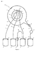
図1および図2は、全血を、血漿成分(本質的に血漿を含有する)と、赤血球成分(本質的に赤血球を含有する)とに分離するように、または、血漿成分と、赤血球成分と、血小板および単核球を含有する中間成分とに分離するように適合されたバッグのセットの一例を示す。このバッグセットは、可撓性のある分離バッグ1と、これに接続された4つの可撓性のあるサテライトバッグ2、3、4、5と、を備える。分離バッグ1は、略円形の外側縁7および内側縁8を有する環状分離チャンバ6を備える。分離チャンバ6の外側円形縁7および内側円形縁8は、実質的に同心である。分離チャンバ6は、分離チャンバ6の内容物を第4のサテライトバッグ5内に排出するのを助けるために外側縁7から外向きに突出する第1の鋭角の漏斗状延長部9を備える。また、分離チャンバ6は、漏斗分離された成分を第1、第2および第3のサテライトバッグ2、3、4内に流し込むのを助けるために、円形縁8からバッグ1の中心へ向けて突出する第2の鈍角の漏斗状延長部10を備える。
1 and 2 show that whole blood is separated into a plasma component (essentially containing plasma) and a red blood cell component (essentially containing red blood cells), or a plasma component and a red blood cell component. And an example set of bags adapted to separate into an intermediate component containing platelets and mononuclear cells. This bag set includes a
分離バッグ1は、環状チャンバ5の内側縁8に接続されている半可撓性ディスク形状接続要素11をさらに備える。ディスク形状接続要素11は、後述する遠心分離機のロータの3つのピンチ弁部材42、43、44(図2の点線に概略的に示されている)を部分的に囲繞するために、第2の漏斗状延長部10に面する内側縁に3つの丸みを帯びた窪み12を備える。ディスク形状接続要素11は、分離バッグ1を遠心分離機のロータに接続するために、一連の穴13を備える。
The
第1のサテライトバッグ2は、2つの目的を有し、全血収集バッグとして且つ中間成分バッグ(第1の分離プロトコル、後述する)として、または、全血収集バッグとして且つ廃棄物バッグ(第2の分離プロトコル、後述する)として、連続して使用される。第1のサテライトバッグ2は、当初は、分離プロセス前に供血者から一定容量の全血(通常、約450ml)を受け取り、分離プロセス中に、中間成分(第1の分離プロトコル)か、または、中間成分と使用済み洗浄液との廃棄混合物(第2の分離プロトコル)か、のいずれかを受け取るように意図されている。第1のサテライトバッグ2は、平らであり実質的に矩形であり、バッグをかけるための穴14を有する2つの補強イヤを上部隅に備える。第1のサテライトバッグ2は、第1のサテライトバッグ2の上部縁に接続された第1の端および内側環状縁8近くで第2の漏斗状延長部10に接続された第2の端を有する第1の移送チューブ20によって、分離バッグ1に接続されている。第1のサテライトバッグ2は、一定容量の抗凝固剤溶液(典型的に、約450mlの供血用に、約63mlのクエン酸リン酸デキストロースの溶液)を収容する。移送チューブ20に装着された破断可能なコネクタ21が、第1の移送チューブ20を通って液体が流れるのを阻止し、抗凝固剤溶液が第1のサテライトバッグ2から分離バッグ1内に流れるのを防止する。
The
バッグセットは、一方の端で第1のサテライトバッグ2の上部縁に接続され、他方の端に、シース23によって保護された針を備える収集チューブ22をさらに備える。収集チューブ22には、クランプ24が嵌められている。
The bag set further comprises a
第2のサテライトバッグ3は、当初は、赤血球用の所定の容量の洗浄液を収容するように意図されている。第1の分離プロトコルでは、第2のサテライトバッグ3はまた、分離プロセス中に、使用済み洗浄液を収集するためにも使用される。第2のサテライトバッグ3は、平らであり実質的に矩形であり、バッグをかけるための穴14を有する2つの補強イヤを上部隅に備える。第2のサテライトバッグ3は、第2の移送チューブ25によって分離バッグ1に接続されている。第2の移送チューブ25は、第2のサテライトバッグ3の上部縁に接続された第1の端と、内側円形縁8近くで、第2の漏斗状延長部10の先端に対して第1の移送チューブ20の第2の端とは反対側に、第2の漏斗状延長部10に接続された第2の端と、を有する。移送チューブ25に装着された破断可能なコネクタ21が、第2の移送チューブ25を通って液体が流れるのを阻止し、洗浄液が第2のサテライトバッグ3から分離バッグ1内に流れるのを防止する。
The
第3のサテライトバッグ4は、血漿成分を受け取るように意図されている。第3のサテライトバッグ4は、平らであり実質的に矩形であり、バッグをかけるための穴14を有する2つの補強イヤを上部隅に備える。第3のサテライトバッグ4は、第3の移送チューブ26によって分離バッグ1に接続されている。第3の移送チューブ26は、第3のサテライトバッグ4の上部縁に接続された第1の端と、第2の漏斗状延長部10の先端に接続された第2の端と、を有する。
The third satellite bag 4 is intended to receive plasma components. The third satellite bag 4 is flat and substantially rectangular and is provided with two reinforcing ears in the upper corner with
第4のサテライトバッグ5は、赤血球成分を受け取るように意図されている。第4のサテライトバッグ5は、平らであり実質的に矩形であり、バッグをかけるために穴14を有する2つの補強イヤを上部隅に備える。第4のサテライトバッグ5は、第4の移送チューブ27によって分離バッグ1に接続されている。第4の移送チューブ27は、第4のサテライトバッグ5の上部縁に接続された第1の端と、第1の漏斗状延長部9の先端に接続された第2の端と、を有する。第4の移送チューブ27は、それぞれ白血球除去フィルタ28の入口および出口に接続された2つのチューブセグメントを備える。分離バッグ1に接続されたチューブセグメントには、クランプ24が嵌められている。第4のサテライトバッグ5に接続されたチューブセグメントには、破断可能なコネクタ21が嵌められ、コネクタ21が壊されたときには、分離バッグ1と第4のサテライトバッグ5との間に液体が流れるのを可能にする。フィルタは、たとえば、ポール・コーポレーション(Pall Corporation)が製造したタイプRC2Dのフィルタであってもよい。このようなフィルタは、ディスク形状のケーシングを備え、これに、半径方向の入口ポートおよび出口ポートが、直径対向で接続されている。ケーシングは、ポリカーボネート(GE Lexan HF1140)から作られ、内部容積が約33mlである。ケーシングは、ポリエステル繊維(直径約2ミクロン)の不織ウェブの複数層から構成された濾過媒体で満たされている。第4のサテライトバッグ5は、赤血球用に一定容量の保存溶液を収容する。
The
分離バッグ1の変形例は、偏心である外側円形縁7および/または内側円形縁8を有する分離チャンバ6を含んでもよく、すなわち、分離チャンバ6は、環状ではなく、C字形となるように内側縁8から外側縁7へ延出する半径方向壁を備え。分離チャンバ6は、内側縁および外側縁を含むいずれの形状(分離バッグが遠心分離機のロータに装着されるときには、内側縁は、外側縁よりも遠心分離機のロータの軸に近い)を有してもよく、たとえば、2つの側方向半径方向縁によって境界を定められた環の一部の形状または矩形形状である。この変形例では、すべてのサテライトバッグは、分離バッグの内側縁に接続されてもよい。
Variations of the
また、分離バッグ1は、遠心分離機のロータの平らなサポート表面かまたは円錐台サポート表面かのいずれかに嵌るような形状とすることができる。
The
図1および図2に示されたバッグセットのバッグおよびチューブは、すべて、血液および血液成分に接触するのに適切な可撓性のあるプラスチック材料から作られている。 The bags and tubes of the bag set shown in FIGS. 1 and 2 are all made from a flexible plastic material suitable for contacting blood and blood components.
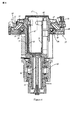
図3および図4は、遠心分離によって一定容量の複合液体を分離するための機器の実施形態を示す。機器は、図1および図2に示された分離バッグのセットを受け取るように適合された遠心分離機と、分離された成分をサテライトバッグ内に移させるための成分移送機構と、を備える。 3 and 4 show an embodiment of an apparatus for separating a fixed volume of composite liquid by centrifugation. The instrument comprises a centrifuge adapted to receive the set of separation bags shown in FIGS. 1 and 2 and a component transfer mechanism for transferring the separated components into the satellite bag.
遠心分離機は、軸受アセンブリ30によって支持されるロータを備え、ロータが垂直中心軸31を中心にして回転するのを可能にする。ロータは、第1の上部部分32と第2の下部部分33とを備える円筒形ロータシャフトであって、シャフトの上部部分32は一部が軸受アセンブリ30を通って延出し、プーリー34が、シャフトの上部部分32の下部端に接続されているロータシャフトと、サテライトバッグを収容するための中心コンパートメント35であって、上部端でロータシャフト32、33に接続されている中心コンパートメント35と、少なくとも1つのサテライトバッグを中心コンパートメント35内の決定された位置に支持するために、中心コンパートメント35および可動バッグローダー87内に嵌るロータライナー79と、分離バッグを支持するための円形ターンテーブル37であって、上部端でコンパートメント35に接続されており、ロータシャフト32、33、コンパートメント35およびターンテーブル37の中心軸は、回転軸31に一致するターンテーブル37と、ターンテーブル37に固定されるバランシングアセンブリ38と、を備える。
The centrifuge includes a rotor supported by the bearing
遠心分離機は、中心垂直軸31を中心にしてロータを回転するために、プーリー34の溝に係合したベルト41によってロータに連結されたモータ40をさらに備える。
The centrifuge further includes a motor 40 coupled to the rotor by a belt 41 engaged with a groove in the
分離機器は、第1、第2および第3のピンチ弁部材42、43、44をさらに備え、これらは、可撓性のあるプラスチックチューブを通って液体が流れるのを選択的に阻止するかまたは可能にするために、且つ、プラスチックチューブを選択的に封止し切断するために、ロータに装着されている。各ピンチ弁部材42、43、44は、細長い円筒形本体と、静止上部ジョーおよび開位置と閉位置との間を動くことができる下部ジョーによって画成される溝を有する頭部と、を備え、溝は、下部ジョーが開位置にあるときには、図1および図2に示されたバッグセットの移送チューブ20、25、26の1本が中にぴったり係合することができるような寸法にされている。細長い本体は、下部ジョーを動かすための機構を含み、これは、プラスチックチューブを封止し切断するのに必要なエネルギを供給する高周波ジェネレータに接続されている。ピンチ弁部材42、43、44は、これらの長手方向軸が同一平面上であり、ロータの中心軸31に平行であり、これらの頭部が中心コンパートメント35のへりより上に突出するように、中心コンパートメント35の周囲に装着されている。分離バッグ1がターンテーブル37に装着されるときに、分離バッグ1およびこれに接続された移送チューブ20、25、26に対するピンチ弁部材42、43、44の位置は、図2に点線で示されている。電力は、ロータシャフトの下部部分33のまわりに装着されているスリップリングアレイ45を通って、ピンチ弁部材42、43、44に供給される。
The separation device further comprises first, second and third
ターンテーブル37は、上部の小さい方の縁がコンパートメント35のへりに接続されている中心円錐台部分47と、円錐台部分47の下部の大きい方の縁に接続された環状の平らな部分48と、環状部分48の外側周囲から上向きに延出する外側円筒形フランジ49と、を備える。ターンテーブル37は、開位置と閉位置との間を旋回するように、ヒンジによってフランジ49に固定されているアーチ形の円形蓋50をさらに備える。蓋50には、ロック51が嵌められ、これによって閉位置で閉塞されることができる。蓋50は、環状内側表面を備え、これは、蓋50が閉位置にあるときには、ターンテーブル37の円錐台部分47および環状の平らな部分48とともに、実質的に平行四辺形の形状を有する半径方向断面を有する円錐台環状コンパートメント52を画成するような形状にされている。円錐台環状コンパートメント52(以下、「分離コンパートメント」ともいう。)は、固定容量を有し、図1および図2に示された分離バッグ1を収容するように意図されている。
The
バランシングアセンブリ38は、略リングの形状を有し、中心コンパートメント35の上部端とターンテーブル37の円錐台壁47との間に延出する空間内でロータに装着されている。バランシングアセンブリ38は、断面が半径方向平面に沿って略矩形であるキャビティを画成するリング形状のハウジング53を備える。バランシングアセンブリは、直径がハウジング53のキャビティの半径方向深さよりもわずかに小さい複数の非常に重いボール54をさらに備える。ボール54が互いに接触するときには、ハウジング52の約180度のセクターを占める。
The balancing
成分移送機構は、分離コンパートメント52内の分離バッグを圧搾し且つ分離された成分をサテライトバッグ内に移させるための圧搾システムを備える。圧搾システムは、ターンテーブル37の円錐台部分47および環状の平らな部分48をライニングにするような形状にされている可撓性のある環状ダイヤフラム55を備え、これに対して、小さい方の円形縁および大きい方の円形縁に沿って固定されている。圧搾システムは、ロータシャフトの下部部分33の下部端からロータを通ってターンテーブル37へ延出するダクト57を経由して、可撓性のあるダイヤフラム55とターンテーブル37との間に画成された膨張可能な油圧チャンバ56に油圧液体をポンプ注入し且つこれからポンプ注出するための油圧ポンプステーション60をさらに備える。ポンプステーション60は、回転式流体カップリング58を経由してロータダクト57に流体的に接続された油圧シリンダ62内を動くことができるピストン61を有するピストンポンプを備える。ピストン61は、ピストンロッド62に連結された親ねじ64を動かすステッピングモータ63によって作動される。ステッピングモータ63は、別々のインクリメントまたはステップによって制御されることができ、モータ63の車軸のターンのほんのわずかに対応する各ステップは、ピストン61の小さな直線変位に対応し、且つ、油圧チャンバ56にポンプ注入し且つこれからポンプ注出されている液体の少量の決定された容量にも対応する。油圧シリンダ62はまた、油圧シリンダ62、ロータダクト57および膨張可能な油圧チャンバ56を含む油圧回路内に油圧液体を導入するかまたはこれから油圧液体を引き出すかを選択的に可能にするために、弁66によって制御されたアクセスを有する油圧液体溜65にも接続されている。圧力ゲージ67は、中の油圧を測定するために油圧回路に接続されている。
The component transfer mechanism includes a squeeze system for squeezing the separation bag in the
分離機器は、機器が作動するときに分離バッグ1内で発生する分離プロセスの特徴を検出するために、3つのセンサ70、71、72をさらに備える。3つのセンサ70、71、72は、ロータの回転軸31から異なる距離で蓋50に包埋されており、第1のセンサ70は回転軸31にもっとも近く、第2のセンサ71は回転軸31にもっとも遠く、第3のセンサ72は中間位置を占める。蓋50が閉じているときには、3つのセンサ70、71、72は、図2に示されるように分離バッグ1に面する。第1のセンサ70(以下、「内側センサ」ともいう。)は、第2の漏斗状延長部10に接続された第2の移送チューブ25の端から短い距離で分離チャンバ6上に位置決めされるように、蓋50に包埋されている。内側センサ70は、インタフェース気体/液体、血漿と血小板/単核球層との間のインタフェース、濃厚血小板血漿と単核球との間のインタフェース、および、赤血球を検出することができる。第2のセンサ71(以下、「外側センサ」ともいう。)は、内側縁8から分離チャンバの幅の約3分の2で分離チャンバ6上に位置決めされるように蓋50に包埋され、第2の漏斗状延長部10に対してずれており、一方、第1および第2の移送チューブ20、26のそれぞれの端に対してよりも、第2の移送チューブ25の端により近い。外側センサ71は、液体、たとえば血液を検出することができる。第3のセンサ72(以下、「中間センサ」ともいう。)は、内側縁8から分離チャンバの幅の約3分の1で、実質的に、第2の漏斗状延長部10に接続された第3の移送チューブ26の端と同一の半径で、分離チャンバ6上に位置決めされるように蓋50に包埋される。中間センサ72は、血漿と血液細胞との間のインタフェースを検出することができる。各センサ70、71、72は、赤外線LEDおよびフォトデテクタを含むフォトセルを備えることができる。電力は、スリップリングアレイ45を通って、センサ70、71、72に供給される。
The separation device further comprises three
分離機器は、制御ユニット(マイクロプロセッサ)と、様々な分離プロトコルに関する情報およびプログラムされた指令を且つこのような分離プロトコルにしたがった機器の動作に関する情報およびプログラムされた指令をマイクロプロセッサに提供するためのメモリと、を含むコントローラ80をさらに備える。特に、マイクロプロセッサは、分離プロセスの様々な段階中にロータが回転する遠心分離スピードに関連する情報を、且つ、分離された成分が分離バッグ1からサテライトバッグ2、3、4内に移される様々な移送流量に関連する情報を受け取るようにプログラムされている。様々な移送流量に関連する情報は、たとえば、油圧回路の油圧液体流量として、または、油圧ポンプステーション60のステッピングモータ63の回転スピードとして表すことができる。マイクロプロセッサは、メモリから直接にまたはメモリを通して、圧力ゲージ67からおよびフォトセル70、71、72から情報を受け取るように、且つ、選択された分離プロトコルに沿って分離機器を作動させるように、遠心分離機モータ40、ステッピングモータ63、および、ピンチ弁部材42、43、44を制御するように、さらにプログラムされている。
The separation equipment provides a control unit (microprocessor) with information and programmed instructions regarding various separation protocols and information about the operation of the equipment according to such separation protocols and programmed instructions to the microprocessor. And a
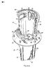
ロータは、サテライトバッグ、移送チューブおよび白血球除去フィルタを受け取るために、且つ、決定された位置にバッグを保持するために、中心コンパートメント35内に嵌るロータライナー79と、ロータライナー内に嵌るバッグローダー87と、をさらに備える。図5〜図8は、ロータライナー79およびバッグローダー87の実施形態を示す。バッグローダー87の機能の1つは、少なくとも1つのサテライトバッグをロータの中心コンパートメント35内に取り付け、且つ/または、これから取り外すためのバッグ取付機構として作用することである。ロータライナー79の機能の1つは、バッグローダー87が中心コンパートメント35内に挿入され且つこれから除去されるときにバッグローダー87を中心コンパートメント35内にガイドするための、且つ、ロータ内の決定された位置にバッグローダー87を位置決めするための、ガイド手段として作用することである。
The rotor receives a satellite bag, transfer tube and leukocyte removal filter, and holds the bag in place, a
ロータライナー79は、底壁80および側方向壁81を有する容器120と、側方向壁81の上部へりのわずかに下で容器120に接続されているフランジ82と、を備える。
The
側方向壁81は、実質的に、上向きにフレア状である円錐台によって画成され、これは、円錐台の軸に平行に延出する平らな平面によって交差される。側方向壁81は、したがって、円錐台のセクターである第1の部分を有し、平らであり平行四辺形の形状を有する第2の部分に接続されている。側方向壁81の第1の部分を部分的に画成する円錐台の軸(これはまた、ロータライナー79の長手方向軸も形成する)は、ロータの回転軸31に一致する。円錐台の角度は、約3度である。これは、より開くこともできる。しかし、角度が大きくなればなるほど、サテライトバッグを保管するためのロータライナー79内部の利用可能な空間が小さくなる。
The
側方向壁81の上部へりは、これの円周の約3分の2上に内向きに曲げられ、狭い円形リップ84を形成するようにし、これの下にチューブのループがくっつくことができる。リップ84は、ロータライナー79の長手方向軸に実質的に垂直である平面に延出する。
The upper edge of the
フランジ82は環状であり、約85度の角度で下向きにフレア状である円錐台の形状を有する。円に配列された一連の丸みを帯びたピン83が、フランジ82から上向きに突出する。ピン83のサイズおよび位置は、分離バッグ1の半可撓性ディスク形状接続要素11の穴13のサイズおよび位置に対応する。ピン83は、分離バッグ1をロータ上に位置決めするのを助け、ロータが回転しているときに分離バッグ1がロータに対して動くことを防止する。フランジ82は、ロータライナー79の側方向壁81の平らな部分に沿って、隣接する平らな壁に部分的に進入する3つの整列配置された円筒形開口部85を備える。ロータライナー79がロータの中心コンパートメント35に完全に挿入されると、3つのピンチ弁部材42、43、44は、ピンチ弁部材の頭部がフランジ82より上に突出するように開口部85を通って延出する。幾分複雑な幾何学形状の3つのガイド要素126、128、129が、フランジ82の内側周囲に沿って突出し、3つの開口部85を部分的に囲繞し、3つの狭いゲート86の境界を定め、これによって、ピンチ弁部材42、43、44に係合したチューブを、決定された方向に沿って中心コンパートメント35内にガイドすることができる。
The flange 82 is annular and has the shape of a truncated cone that is flared downward at an angle of about 85 degrees. A series of
バッグローダー87は、ロータライナー79内に嵌るような寸法にされ、ロータライナーに完全に係合されたとき、液体で満たされた少なくとも1つのサテライトバッグを支持し、且つ、選択されたスピードでロータが回転するときにサテライトバッグに接続された分離バッグ内にサテライトバッグの内容物が完全に移されるようにこれを保持するサポート部材を形成するような寸法にされる。サポート部材は、これに固定されたサテライトバッグが、移送チューブが接続されている上部部分よりも、ロータの回転軸31により近い下部部分を有するように設計されている。
The
サポート部材は、ロータの回転軸31に対して傾斜している壁の部分を備える。上部部分によって傾斜した壁の上部部分に固定されたサテライトバッグは、ロータの回転中に遠心力によって傾斜した壁に対して押圧され、このため、サテライトバッグの下部部分は上部部分よりも回転軸に近い。
The support member includes a wall portion inclined with respect to the
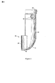
バッグローダー87は、主に、少なくとも1つのサテライトバッグの上部部分をバッグローダー87に着脱自在に固定するための固定機構を備える上部部分と、少なくとも1つのサテライトバッグの下部部分を収容するためのレセプタクルを備える下部部分と、上部部分を下部部分に接続し、バッグローダー87の上部部分に固定された上部部分およびレセプタクルに挿入された下部部分を有するサテライトバッグの中間部分を露出する中間部分と、を備える。
The
より詳細には、ローダー87は、ロータライナー79の高さ上に延出する第1の外側のガター状の壁88と、バッグローダーの底部からロータライナー79の8番目の約3分の1上に延出する第2の内側のガター状の壁89と、を有する。内側および外側の壁88、89は、内側壁89の凹面が外側壁88の凹面に面するように、これらの側方向縁に沿って接続されている。第1の外側壁88の内側表面は、角度が約3度である円錐台壁のセクターによって画成されている。バッグローダー87は、外側壁88の内側表面を画成する円錐台の中心軸に一致する長手方向軸を有する。バッグローダー87がロータの中心コンパートメント35に完全に挿入されたとき、バッグローダー87の長手方向軸は、ロータの回転軸31に一致する。第2の内側壁89は、バッグローダー87の長手方向軸に平行な長手方向軸を有する円筒のセクターである。2つの壁88、89の寸法およびこれらの間の距離は、内側壁89のいずれの点からもバッグローダー87の長手方向軸に対する距離が、この長手方向軸から外側壁88に固定されたサテライトバッグの入口/出口が位置する外側壁88の点(窪み94、95)の距離よりも短いように選択される。これにより、バッグローダーに取り付けられたサテライトバッグが、遠心力下で、サテライトバッグの全内容物をこれに取り付けられた分離バッグへ移すことができるロータの領域に確実に閉じ込められるようにする。バッグローダー87は、第2の内側壁89(円筒のセクター)の下部へりに接続されている、長手方向軸に垂直である平らな部分90と、平らな部分90から、平らな底部分90からのバッグローダー87の高さの約5分の1で、第1の外側壁88(円錐台のセクター)の中央長手方向軸に位置する点へ上昇する湾曲したS字型部分91と、を有する底壁をさらに備える。幾何学的な点から、バッグローダー87の底部の第2の部分91は、円錐台と垂直軸を有する円筒との交点から生じる。第2の内側壁89、第2の内側壁89に接続されている第1の外側壁88の下部部分、および、これに接続された底壁90、91は、バッグローダー87に取り付けられたサテライトバッグの下部部分用にレセプタクル96を形成する。このレセプタクルは、サテライトバッグの下部部分がロータライナー79の内側表面と相互作用するのを防止することによって、バッグローダー87をロータの中心コンパートメント34内に挿入するのを容易にする。
More specifically, the
バッグローダー87は、これの上部部分に、以下に述べるバッグホルダ100の相補的な係止要素の端を着脱自在に受けて係止するために、内側表面で開口する2つの側方向窪み92を含む固定手段をさらに備える。狭いさねの形態のガイド93が、バッグホルダ100を適所に設定するのを助けるために、各窪み92の底部からバッグローダー87の側方向縁へ向けて延出する。バッグローダー87は、2つの係止窪み92の間に、サテライトバッグの上部部分に包埋された移送チューブの端を収容するために2つの他の窪み94、95を備える。
The
図9および図10に示されたバッグホルダ100は、遠心分離機の動作中にサテライトバッグ2、3、4をローダー87の決定された位置に固定するために使用される。
The
バッグホルダ100は、細長い平らな本体101を備え、本体101の中央に、平らなU字形の取扱付属物102が接続され、バッグホルダ100がバッグローダー87に装着されるときに上向きに突出するようにする。細長い平らな本体101は、側部AおよびBの両方に2つの平行なガター状ガイド103、104が嵌められ、これらは、細長い平らな本体101の長手方向軸に垂直であり、細長い平らな本体101の中心部分に延出し、実質的に、それぞれ、U字形の取扱付属物102の側方向縁に整列配置する。バッグホルダ100がバッグローダー87に固定されたとき、細長い平らな本体101は実質的に垂直であり、ガター状ガイド103、104はロータの回転軸31に実質的に平行である。ガター状ガイド103、104は、移送チューブ20、25、26の一部または針シース23が中にぴったり係合することができるような寸法にされている。
The
バッグホルダ100は、少なくとも1つのサテライトバッグ2、3、4、5をローダー87に吊すために細長い平らな本体101に接続された第1の組のペグ107、108の形態の吊し機構をさらに備える。ペグ107、108は、細長い平らな本体101の側部Aから垂直に延出する。2つのペグ107、108の間の距離は、実質的に、サテライトバッグ2、3、4、5のイヤの穴14の間の距離と同一である。ペグ107、108の断面は、実質的に、穴14に嵌る。
The
ペグ107、108はまた、バッグホルダ100をローダー87に固定するためにも使用される。この目的のために、2つのペグ107、108の間の距離は、実質的に、ローダー87の上部部分の2つの係止窪み92の間の距離と同一である。また、各ペグ107、108の先端には、ローダー87の係止窪み92内に着脱自在に係止することができる係止要素109、110が嵌められている。各係止要素109、110は、丸みを帯びた端を有する可撓性のあるプレートから構成され、これは、対応するペグ107、108に垂直に接続されている。
The
バッグホルダ100は、分離バッグ1を、および、場合によってはサテライトバッグ2、3、4、5を、これへ解放可能に固定するために細長い平らな本体101に接続された第2の組のペグ111、112をさらに備える。ペグ111、112は、ペグ107、108と同一の軸に沿って細長い平らな本体101の側部Bから垂直に延出する。ペグ111、112の先端には、ペグに係合されたサテライトバッグがバッグアセンブリの遠心分離中にペグから離脱するのを防止するために、保持要素113、144が嵌められている。全体的に、第2の組のペグ111、112は、ペグの長さを除いては、第1の組のペグ107、108と同一であり、長さは、第1の組の方が第2の組よりも長い。
The
バッグローダー87がロータライナー79に完全に係合されたとき、ペグに係合したサテライトバッグ2、3、4、5がロータの中心コンパートメント35の決定された位置を占めることは、細長い平らな本体101および第1および第2の組のペグ106、107、111、112のそれぞれの配列によって生じる。さらに、ロータが回転を開始するとき、第1の組のペグ106、107の機構によってバッグローダー87に装着された液体で満たされたサテライトバッグが、遠心力によってローダー87の円錐台壁88および丸みを帯びた底部部分91にくっつき、このため、バッグの上部部分は、バッグの下部部分よりも、ロータの回転軸31からさらに遠く離れる。この配置のおかげで、サテライトバッグを分離バッグに接続する移送チューブが開き回転スピードが十分に高いときには、当初サテライトバッグに収容されていた液体は、完全に分離バッグ内に排出する。
When the
全血供血から、3つの血液成分、すなわち、血漿成分と、血小板/単核球成分と、洗浄された赤血球成分と、を準備することを目的とする第1の分離プロトコルの例が、以下に説明される。 An example of a first separation protocol aimed at preparing three blood components from a whole blood donation: a plasma component, a platelet / mononuclear cell component, and a washed red blood cell component is as follows: Explained.
第1の分離プロトコルに沿った分離機器の動作は、以下の通りである。 The operation of the separation device according to the first separation protocol is as follows.
第1段階(第1のプロトコル):図1、図2に示されたようなバッグセットが、(図3、図4に示されるように)遠心分離機のロータの適所に設定される。 First stage (first protocol): A bag set as shown in FIGS. 1 and 2 is set in place on the centrifuge rotor (as shown in FIGS. 3 and 4).
第1段階の開始時に、図1のバッグセットの第1のサテライトバッグ2は、一定容量の抗凝固処理全血(通常、約500ml)を収容し、第2のサテライトバッグ3は、一定容量の洗浄液(通常、約350mlの塩水)を収容する。収集チューブ22は、封止され、切断されている。第4のサテライトバッグ5を分離バッグ1に接続する移送チューブ27のクランプ24は、閉じている。第1のサテライトバッグ2および第2のサテライトバッグ3は、(図9、図10に示される)バッグホルダ100の第1の組のペグ107、108に係合し、第1のサテライトバッグ2が先に係合されている。第3のサテライトバッグ4および第4のサテライトバッグ5は、第2の組のペグ111、112に係合している。サテライトバッグ2、3、4、5は、バッグローダー87に挿入され、バッグホルダ100は、バッグホルダ100の可撓性のある係止要素109、110をバッグローダー87の係止窪み92内に強制的に係合することによって、バッグローダー87に固定され、この結果、第1のサテライトバッグ2はバッグローダー87の内側表面に隣接する。次いで、バッグローダー87は、遠心分離機の中心コンパートメント35内に完全に挿入され、この中で、バッグローダー87はロータライナー79によってガイドされている。次いで、サテライトバッグ2、3、4、5は、実質的に、ロータの回転軸31を含む平面の一方の側部に位置する。
At the start of the first phase, the
分離バッグ1は、ターンテーブル37に置かれ、ロータライナー79のフランジ82のピン83は、分離バッグ1のディスク形状接続要素11の穴13に係合している。第1のサテライトバッグ2を分離バッグ1に接続する第1の移送チューブ20は第1のピンチ弁部材42に係合し、第2のサテライトバッグ3を分離バッグ1に接続する第2の移送チューブ25は第2のピンチ弁部材43に係合し、第3のサテライトバッグ4を分離バッグ1に接続する第3の移送チューブ26は第3のピンチ弁部材44に係合する。第1のサテライトバッグ2と分離バッグ1との間、および、第2のサテライトバッグ3と分離バッグ1との間の連通を阻止する破断可能なピン21が、壊される。ロータの蓋49は、閉じている。
The
第2段階(第1のプロトコル):第1のサテライトバッグ2に収容された抗凝固処理全血が分離バッグ1に移される。
Second stage (first protocol): The anticoagulated whole blood contained in the
第2段階の開始時に、第1のピンチ弁部材42は開き、第2および第3のピンチ弁部材43、44は閉じている。ロータは遠心分離機モータ40によって動くように設定され、ロータの回転スピードは徐々に増加し、ついには、以下のように選択される第1の遠心分離スピード(たとえば、約1500RPM)に到達する。すなわち、
・遠心力下で、第1のサテライトバッグ2の内容物を分離バッグ1に移させるのに十分に高いスピード、
・より短時間で移送全体を起こさせるほど十分に高いスピード、
一方、同時に、
・第1のサテライトバッグ2内の圧力が、超えれば溶血が発生する決定された圧力閾値を実質的に超えさせないほど十分に低いスピード、
・分離バッグ1に入る血液の流れに、溶血を発生させる剪断力を生成させないほど十分に低いスピード、
である。
At the start of the second stage, the first
A sufficiently high speed to transfer the contents of the
A sufficiently high speed to cause the entire transfer to occur in a shorter time,
Meanwhile, at the same time
A speed sufficiently low that the pressure in the
A sufficiently low speed so as not to generate shear forces that generate hemolysis in the blood flow entering the
It is.
サテライトバッグ2内で超えれば溶血が発生する圧力閾値は約10PSIであり、このような圧力閾値に到達せず且つ分離バッグに入る血液の流れにおける剪断力が溶血を発生させない最大回転スピードは、約1800RPMであると決定されている。約1500RPMの回転スピードで、約500mlの抗凝固処理全血を第1のサテライトバッグ2から分離バッグ1に移すのに、約1分かかる。
The pressure threshold at which hemolysis occurs if it exceeds within the
外側セル71が血液を検出したとき、第3のサテライトバッグ4(この中に後に血漿成分が移される)に接続された第3の移送チューブ26を通る流体の流れを制御する弁部材44が、血液を分離バッグ1の中に注ぐときに空気が分離バッグ1から出るのを可能にするように、所定の時間の間(たとえば、約30秒)、開けられる。
When the
外側セル71が、遠心分離プロセスの開始後所定の時間内に血液を検出していない場合には、制御ユニット80は、ロータを停止させ、警告を発生させる。これは、特に、第1の移送チューブ20の破断可能なコネクタ21が、誤って壊れていない場合に、発生する可能性がある。
If the
第3段階(第1のプロトコル):分離チャンバ1内の空気が、第1のサテライトバッグ2内に追い出され、この中に、血小板/単核球成分が後に移される。
Third stage (first protocol): the air in the
第3段階の開始時に、第1のサテライトバッグ2の全内容物は、分離バッグ1内に移されており、第1のピンチ弁部材42は開き、第2および第3のピンチ弁部材43、44は閉じている。ロータは、第1の回転スピード(約1500RPM)で回転する。ポンプステーション60は、一定の流量(たとえば、約240ml/分)で油圧液体を油圧チャンバ56内にポンプ注入し、その後、分離バッグ1を圧搾するように作動される。分離バッグ1内の空気は、第1のサテライトバッグ2内に追い出され、第1のサテライトバッグ2には、後に血小板/単核球成分が移される。内側センサ70によるインタフェース空気/液体の検出後所定の時間後に、ポンプステーション60は停止され、第1のピンチ弁部材42は閉じられる。
At the start of the third stage, the entire contents of the
第4段階(第1のプロトコル):分離チャンバ内の血液成分が、所望の層へ沈殿する。 Fourth stage (first protocol): blood components in the separation chamber settle to the desired layer.
この段階の開始時に、3つのピンチ弁部材42、43、44は閉じている。ロータのスピードは、血液成分が所望のレベルで沈殿する第2の高い遠心分離スピード(たとえば、約3200RPM、いわゆる「ハードスピン」)に到達するまで、徐々に増加する。ロータは、分離バッグ1に当初移された全血のヘマトクリット値がどの値であれ、所定の期間の終了時に、血液が、分離バッグ1内に、外側環状赤血球層のヘマトクリット値が約90%であり内側環状血漿層が実質的に細胞を含まないところまで沈殿するように選択される所定の時間(たとえば、約220秒)、第2の遠心分離スピードで回転される。より詳細には、この沈殿段階の結果、分離バッグ1は4つの層、すなわち、主に血漿を含有する第1の内側層と、主に血小板を含有する第2の中間層と、主に白血球(リンパ球、単球および顆粒球)を含有する第3の中間層と、主に赤血球を含有する第4の外側層と、を呈し、第3の層および第4の層は、部分的にオーバーラップする(顆粒球は第4の層に部分的に包埋されている)
第5段階(第1のプロトコル):血漿成分は、第3のサテライトバッグ4内に移される。
At the start of this stage, the three
Fifth stage (first protocol): the plasma component is transferred into the third satellite bag 4.
この段階の開始時に、3つのピンチ弁部材42、43、44は閉じている。ロータは、沈殿段階と同一の高い遠心分離スピードで回転される。所定の沈殿期間の終了前に発生する可能性がある、中間センサ72が外向きに動いている血漿/血液細胞インタフェースを検出した後の所定の時間後に、第3のサテライトバッグ4へのアクセスを制御する第3のピンチ弁部材44は開き、ポンプステーション60は、一定の流量(たとえば、約220ml/分)で油圧液体を油圧チャンバ56内にポンプ注入するように作動される。膨張する油圧チャンバ56は、分離バッグ1を圧搾し、血漿を第3のサテライトバッグ4内に移させる。内側センサ70による血漿/血液細胞インタフェースの検出後所定の時間が経過した後に、ポンプステーション60は停止され、第3のピンチ弁部材44は閉じられる。この段階の終了時に、血漿の総容量の第1の主要部分は第3のサテライトバッグ4内にあり、一方、血漿の総容量の第2の残りの部分は、分離バッグ1内に残っている。
At the start of this stage, the three
血漿成分の移送流量(これは直接、油圧流体の流量に関する)は、血漿成分を血小板で不純にするのを避けるように、血小板層を乱すことなく、できるだけ高くなるように選択される。 The plasma component transfer flow rate (which directly relates to the flow rate of the hydraulic fluid) is selected to be as high as possible without disturbing the platelet layer so as to avoid impairing the plasma component with platelets.
第6段階(第1のプロトコル):血小板/単核球成分が、第1のサテライトバッグ2内に移される。
Sixth stage (first protocol): The platelet / mononuclear cell component is transferred into the
第6段階は、第3のピンチ弁部材44が第5段階の終了時に閉じられるとすぐに開始することができる。この第5段階の開始時に、ピンチ弁部材42、43、44は閉じている。ロータは、先のものと同一の高い遠心分離スピードで回転される。第1のサテライトバッグ2へのアクセスを制御する第1のピンチ弁部材42は開き、ポンプステーション60は、一定の流量(たとえば、約140ml/分)で油圧液体を油圧チャンバ56内にポンプ注入するように作動される。膨張する油圧チャンバ56は、分離バッグ1を圧搾し、血漿の残りの容量、血小板、リンパ球、単球および少量の赤血球を含有する血小板/単核球成分を第1のサテライトバッグ2内に移させる。油圧チャンバ56内にポンプ注入された決定された容量の油圧液体(これは、今度は、ステッピングモータ63の多数のステップによって決定することができる)に対応する所定容量が、第1のサテライトバッグ2内に移された後に、ポンプステーション60は停止され、第1のピンチ弁部材42は閉じられる。
The sixth stage can begin as soon as the third
たとえば、血小板/単核球成分の所定容量は、約5mlの血漿および約5mlの赤血球を含んで、約10〜15mlの間で設定することができる。 For example, the predetermined volume of the platelet / monocyte component can be set between about 10-15 ml, including about 5 ml plasma and about 5 ml red blood cells.
第7段階(第1のプロトコル):一定容量の洗浄液が、第2のサテライトバッグ3から分離バッグ1内に移される。
Seventh stage (first protocol): A fixed volume of cleaning solution is transferred from the
この段階の開始時に、3つのピンチ弁部材42、43、44は閉じている。遠心分離機のスピードは、ポンプステーション60が油圧チャンバ56から油圧液体をポンプ注出することができる第3の遠心分離スピード(たとえば、約1000RPM)へ減少する。ポンプステーション60は、第2のサテライトバッグ3の洗浄液の容量に対応する一定容量の油圧液体を油圧チャンバ56からポンプ注出するように作動される。ポンプステーション60は、速い流量(たとえば、500ml/分)で油圧液体をポンプ注入するように制御される。
At the start of this stage, the three
第2のピンチ弁部材43は、第2のサテライトバッグ3に収容される洗浄液の総容量を、遠心力下で、分離バッグ1内に移すことができるように、所定の時間の間開いている。
The second
第8段階(第1のプロトコル):赤血球が、洗浄液と混合される。 Eighth stage (first protocol): Red blood cells are mixed with a washing solution.
この段階の開始時に、3つのピンチ弁部材42、43、44は閉じている。
At the start of this stage, the three
一実施形態において、ロータの回転スピードは、ロータが停止するまで減少する。モータ40は、混合のために、所定の時間の間、各方向に、決定された角度(たとえば、180度)で、ロータを前後に回転するように制御される。 In one embodiment, the rotational speed of the rotor decreases until the rotor stops. The motor 40 is controlled to rotate the rotor back and forth at a determined angle (eg, 180 degrees) in each direction for a predetermined time for mixing.
別の変形例において、ロータの回転スピードは、決定された時間の間、第3の回転スピードから第4の回転スピード(たとえば、2500RPM)へ、周期的に急増および急減する。 In another variation, the rotational speed of the rotor rapidly increases and decreases periodically from a third rotational speed to a fourth rotational speed (eg, 2500 RPM) for a determined time.
第9段階(第1のプロトコル):赤血球と洗浄液との混合物が、所望の層へ沈殿する。 Ninth stage (first protocol): A mixture of red blood cells and washing solution is precipitated into the desired layer.
この段階の開始時に、3つのピンチ弁部材42、43、44は閉じている。
At the start of this stage, the three
ロータのスピードは、赤血球が上清(血漿およびおそらく望ましくないタンパク質およびウイルスを含む使用済み洗浄液)から分離される第2の高い遠心分離スピード(たとえば、約3200RPM)に到達するまで徐々に増加する。より詳細には、ロータは、混合物内の赤血球の濃度が何であれ、所定の期間の終了時に、赤血球が、外側環状赤血球層のヘマトクリット値が約90%であり内側環状上清層が実質的に細胞を含まないところまで沈殿するように選択される。 The rotor speed is gradually increased until it reaches a second high centrifugation speed (eg, about 3200 RPM) where the red blood cells are separated from the supernatant (plasma and spent wash containing possibly unwanted proteins and viruses). More particularly, the rotor is substantially free of red blood cells at the end of a given period, with a hematocrit value of the outer annular red blood cell layer of about 90% and an inner annular supernatant layer, whatever the concentration of red blood cells in the mixture. It is selected to settle to a point that does not contain cells.
第10段階(第1のプロトコル):上清成分が、第2のサテライトバッグ3(当初は、洗浄液を収容していた)内に移される。 Tenth stage (first protocol): The supernatant components are transferred into the second satellite bag 3 (which initially contained the wash solution).
この段階の開始時に、3つのピンチ弁部材42、43、44は閉じている。ロータは、沈殿段階と同一の高い遠心分離スピードで回転される。所定の沈殿期間の終了前に発生する可能性がある、中間センサ72が外向きに動いている上清/血液細胞インタフェースを検出した後の所定の時間後に、第2のサテライトバッグ3へのアクセスを制御する第2のピンチ弁部材43は開き、ポンプステーション60は、一定の流量(たとえば、約220ml/分)で油圧液体を油圧チャンバ56内にポンプ注入するように作動される。膨張する油圧チャンバ56は、分離バッグ1を圧搾し、廃棄物バッグとして使用される第2のサテライトバッグ3内に上清成分を移させる。内側センサ70による上清/血液細胞インタフェースの検出後所定の時間が経過した後に、ポンプステーション60は停止され、第2のピンチ弁部材43は閉じられる。この段階の終了時に、分離バッグは、本質的に、洗浄された赤血球を収容している。
At the start of this stage, the three
第11段階(第1のプロトコル):遠心分離プロセスが終了する。 Eleventh stage (first protocol): the centrifugation process ends.
ロータの回転スピードは、ロータが停止するまで減少し、ポンプステーション60は、油圧チャンバ56が実質的に空になるまで高い流量(たとえば、約800ml/分)で油圧液体を油圧チャンバ56からポンプ注出するように作動され、ピンチ弁部材42、43、44は、移送チューブ20、25、26を封止し切断するように作動される。洗浄された赤血球は、分離バッグ1内に残っている。
The rotational speed of the rotor decreases until the rotor stops, and the
第12段階(第1のプロトコル):赤血球成分が、第4のサテライトバッグ5内に移される。
Twelfth stage (first protocol): The red blood cell component is transferred into the
ロータの蓋50が開かれ、第4のサテライトバッグ5に接続された分離バッグ1が、これから取り外される。移送チューブ27のクランプ24は開いている。第4のサテライトバッグ5と白血球除去フィルタ28との間の連通を阻止する破断可能なコネクタ21が壊される。第4のサテライトバッグ5に収容された保存溶液が、重力によって、フィルタ28を通って分離バッグ1内に流れることができ、そこで、粘度を低くするように赤血球と混合される。次いで、分離バッグ1の内容物は、重力によって、フィルタ28を通って第4のサテライトバッグ5内に流れることができる。白血球(顆粒球および残りの単球およびリンパ球)は、フィルタ28によって捉えられ、このため、第4のサテライトバッグ5内の最終的な濃厚赤血球は、望ましくないタンパク質およびウイルスが実質的に除去されるのに加えて、実質的に白血球を含まず、1濃厚赤血球成分当たり5×10⁶未満の白血球というAABB(米国血液銀行協会(American Association of Blood Banks))の基準に合致する。
The
全血供血から2つの血液成分を、すなわち、血漿成分と(2回洗浄された)赤血球成分とを準備することを目的とする第2の分離プロトコルの例が、以下に説明される。 An example of a second separation protocol aimed at preparing two blood components from a whole blood donation, namely a plasma component and a red blood cell component (washed twice) is described below.
第2のプロトコルは、第1のプロトコルとは、本質的に、以下の点で異なる。 The second protocol is essentially different from the first protocol in the following points.
・赤血球は、1回ではなく、2回洗浄される。 • Red blood cells are washed twice instead of once.
・各分離段階後に、上清成分が、廃棄物バッグとして使用される第1のサテライトバッグ2内に移される。
-After each separation step, the supernatant components are transferred into the
・血小板/単核球成分は、さらなる処理のために隔離されるのではなく、上清成分とともに廃棄される。 The platelet / mononuclear cell component is discarded with the supernatant component rather than being sequestered for further processing.
第2の分離プロトコルに沿った分離機器の動作は、以下の通りである。 The operation of the separation device according to the second separation protocol is as follows.
第1〜第6段階(第2のプロトコル)は、第1のプロトコルの第1〜第6段階と同一である。 The first to sixth stages (second protocol) are the same as the first to sixth stages of the first protocol.
第7段階(第2のプロトコル):決定された容量の洗浄液が、第2のサテライトバッグ3から分離バッグ1内に移される。
Seventh stage (second protocol): The determined volume of the cleaning solution is transferred from the
この段階の開始時に、ピンチ弁部材42、43、44は閉じている。遠心分離機のスピードは、ポンプステーション60が油圧チャンバ56から油圧液体をポンプ注出することができる第3の遠心分離スピード(たとえば、約1000RPM)へ減少する。ポンプステーション60は、第2のサテライトバッグ3の洗浄液の総容量の半分に対応する一定容量の油圧液体を油圧チャンバ56からポンプ注出するように作動される。ポンプステーション60は、速い流量(たとえば、500ml/分)で油圧液体をポンプ注入するように制御される。
At the start of this stage, the
第2のピンチ弁部材43は、第2のサテライトバッグ3に収容される洗浄液の総容量の半分を、遠心力下で、分離バッグ1内に移すことができるように、所定の時間の間、開いている。
The second
第8段階(第2のプロトコル):赤血球が、洗浄液と混合される。 Eighth stage (second protocol): Red blood cells are mixed with a washing solution.
この段階は、本質的に第1のプロトコルの第8段階に対応する。 This stage essentially corresponds to the eighth stage of the first protocol.
第9段階(第2のプロトコル):赤血球と洗浄液との混合物が、所望の層へ沈殿する。 Ninth stage (second protocol): A mixture of red blood cells and washing solution is precipitated into the desired layer.
この段階は、本質的に第1のプロトコルの第9段階に対応する。 This stage essentially corresponds to the ninth stage of the first protocol.
第10段階(第2のプロトコル):上清成分が、血小板/単核球成分が先に移されている第1のサテライトバッグ2内に移される。したがって、この第2のプロトコルによれば、第1のサテライトバッグ2は廃棄物バッグとして使用される。
Tenth stage (second protocol): The supernatant component is transferred into the
この段階の開始時に、3つのピンチ弁部材42、43、44は閉じている。ロータは、沈殿段階と同一の高い遠心分離スピードで回転される。所定の沈殿期間の終了前に発生する可能性がある、中間センサ72が外向きに動いている上清/血液細胞インタフェースを検出した後の所定の時間後に、第1のサテライトバッグ2へのアクセスを制御する第1のピンチ弁部材42は開き、ポンプステーション60は、一定の流量(たとえば、約220ml/分)で油圧液体を油圧チャンバ56内にポンプ注入するように作動される。膨張する油圧チャンバ56は、分離バッグ1を圧搾し、廃棄物バッグとして使用される第1のサテライトバッグ2内に上清成分を移させる。内側センサ70による上清/血液細胞インタフェースの検出後所定の時間が経過した後に、ポンプステーション60は停止され、第1のピンチ弁部材43は閉じられる。この段階の終了時に、分離バッグ1は、本質的に、1回洗浄された赤血球を収容している。
At the start of this stage, the three
第7段階〜第10段階は、1回繰り返され、その結果、サテライトバッグ3に残っている洗浄液の容量の残りの半分が分離バッグ1内に移され、これは、1回洗浄された赤血球と混合され、混合物は、2回洗浄された赤血球と上清成分とを分離するように遠心分離され、上清成分は、既に血小板/単核球成分および使用済み洗浄液の総容量の第1の半分を収容している第1のサテライトバッグ2内に移される。
第2のプロトコルの最後の2つの段階は、第1のプロトコルの第11段階および第12段階と同一である。 The last two stages of the second protocol are identical to the eleventh and twelfth stages of the first protocol.
第2のプロトコルの変形例において、赤血球は、2回洗浄される代わりに、3回以上洗浄されてもよく、たとえば、各回、同一量の洗浄液で洗浄されてもよい。 In a variation of the second protocol, the red blood cells may be washed three or more times instead of being washed twice, for example, each time with the same amount of washing solution.
第3の分離プロトコルは、一定量の全血から2つの血液成分、すなわち、血小板濃厚血漿成分および洗浄された赤血球成分を準備することにある。 The third separation protocol consists in preparing two blood components from a fixed amount of whole blood, namely a platelet-rich plasma component and a washed red blood cell component.
第3のプロトコルによれば、
・分離バッグ1に収容される一定容量の全血は、「ソフトスピン」遠心分離プロセス(たとえば、約2000RPM)を受け、このプロセスの終了時に、分離バッグ1は3つの層を呈する。すなわち、血小板の大半が浮遊している主に血漿を含有する第1の内側層(血小板濃厚血漿)と、主に白血球(リンパ球、単球および顆粒球)を含有する中間層と、主に赤血球を含有する第3の外側層であり、第3の層および第4の層はオーバーラップする(顆粒球は、部分的に第4の層に包埋されている)。
According to the third protocol,
A certain volume of whole blood contained in the
・ロータの回転スピードは同一のままで、血小板濃厚血漿成分は、第3のサテライトバッグ4内に移される。 -The rotational speed of the rotor remains the same, and the platelet-rich plasma component is transferred into the third satellite bag 4.
・次いで、分離バッグ1は、高濃厚赤血球(たとえば、約90ヘマトクリット)から残っている血漿を抽出するために、所定の時間の間、「ハードスピン」遠心分離プロセス(たとえば、約3200RPM)を受ける。
The
・次いで、血漿、単核球および少量の赤血球を含有する単核球成分が、廃棄物バッグとして使用される第1のサテライトバッグ2内に移される。
-The mononuclear cell component containing plasma, mononuclear cells and small amounts of red blood cells is then transferred into the
・次いで、分離バッグ1に残っている濃厚赤血球は、第2のサテライトバッグ3に収容された洗浄液で洗浄される。洗浄は、第2のサテライトバッグ3の全内容物で1回洗浄されるか、または、各回第2のサテライトバッグ3の内容物の一部で2回以上洗浄されるか、のいずれかである。上清は、すべてを1度にかまたは数回に分割して、第1のサテライトバッグ2内に移される。
Next, the concentrated erythrocytes remaining in the
第3のプロトコルの別の実施形態において、単核球成分は、廃棄されずに、血小板濃厚血漿が第3のサテライトバッグ4内に移された後に、赤血球は、所望の回数だけ洗浄される。すべての白血球は、濾過によって最終的な赤血球生成物から除去される。 In another embodiment of the third protocol, the mononuclear cell component is not discarded and the red blood cells are washed as many times as desired after the platelet-rich plasma has been transferred into the third satellite bag 4. All white blood cells are removed from the final red blood cell product by filtration.
本明細書に記載された機器および方法に対して、様々な変更を行うことができることは、当業者には明らかである。したがって、本発明は、明細書に述べた主題に限定されないことを理解すべきである。むしろ、本発明は、変更例および変形例を含むことが意図される。
以下に、本願出願の当初の特許請求の範囲に記載された発明を付記する。
[1]
一定容量の全血を、少なくとも血漿成分と赤血球成分とに分離するための方法であって、
一定容量の全血を収容する分離バッグ(1)を遠心分離して、前記分離バッグ(1)の中で、少なくとも、血漿を含有する第1の成分と赤血球を含有する第2の成分とに分離することと、
前記分離バッグ(1)の遠心分離中に、前記分離バッグ(1)に接続された血漿成分バッグ(4)内に前記第1の成分を移すことと、
前記分離バッグ(1)の遠心分離中に、前記分離バッグ(1)に接続された洗浄液バッグ(3)から前記分離バッグ(1)内に一定容量の洗浄液を移すことと、
前記一定容量の洗浄液を前記第2の成分と混合することと、
前記分離バッグ(1)を遠心分離して、前記分離バッグ(1)の中で、洗浄された赤血球成分と、使用済み洗浄液を含有する上清成分と、を分離することと、
前記分離バッグ(1)の遠心分離中に、前記分離バッグ(1)に接続された廃棄物バッグ(2、3)内に前記上清成分を移すことと、
を備える方法。
[2]
前記分離バッグ(1)に接続された全血バッグ(2)から前記分離バッグ(1)内に前記一定容量の全血を移すことをさらに備える[1]記載の方法。
[3]
前記一定容量の全血は、遠心分離によって、前記全血バッグ(2)から前記分離バッグ(1)内に移される[2]記載の方法。
[4]
前記分離バッグ(1)は遠心分離されて、前記分離バッグ(1)の中で、血漿を含有する第1の成分と、赤血球を含有する第2の成分と、血小板および単核球を含有する中間成分と、に分離する[1]記載の方法。
[5]
前記分離バッグ(1)の遠心分離中に、前記分離バッグ(1)に接続された中間成分バッグ(2)内に前記中間成分を移すことをさらに備える[4]記載の方法。
[6]
前記分離バッグ(1)に接続された前記全血バッグ(2)から前記分離バッグ(1)内に前記一定容量の全血を移すことと、
前記一定容量の全血が前記分離バッグ(1)内に移された後に、前記全血バッグ(2)内に前記中間成分を移すことと、
をさらに備える[4]記載の方法。
[7]
前記一定容量の洗浄液は、遠心分離によって、前記分離バッグ(1)内に移される[1]記載の方法。
[8]
前記分離バッグ(1)内に移される前記一定容量の洗浄液は、実質的に、前記洗浄液バッグ(3)に当初収容された洗浄液の総容量に対応する[1]記載の方法。
[9]
前記上清成分は、前記洗浄液が前記分離バッグ(1)内に移された後に前記廃棄物バッグとして使用される前記洗浄液バッグ(3)内に移される[8]記載の方法。
[10]
前記分離バッグ(1)内に移される前記一定容量の洗浄液は、前記洗浄液バッグ(3)に当初収容された洗浄液の総容量の第1の画分である[1]記載の方法。
[11]
前記分離バッグ(1)に接続された全血バッグ(2)から前記分離バッグ(1)内に前記一定容量の全血を移すことと、
前記一定容量の全血が前記分離バッグ(1)内に移された後に前記廃棄物バッグとして使用される前記全血バッグ(2)内に、前記分離バッグ(1)から前記上清成分を移すことと、
をさらに備える[10]記載の方法。
「12」
廃棄物バッグ(2)内に前記上清成分を移した後に、
前記分離バッグ(1)の遠心分離中に、前記洗浄液バッグ(3)に当初収容された洗浄液の総容量の第2の画分を、前記分離バッグ(1)内に移すことと、
前記洗浄液を前記第2の成分と混合することと、
前記分離バッグ(1)を遠心分離して、前記分離バッグ(1)の中で、洗浄された赤血球成分と、使用済み洗浄液を含有する上清成分と、に分離することと、
前記分離バッグ(1)の遠心分離中に、前記廃棄物バッグ(2)内に前記上清成分を移すことと、
をさらに備える[10]記載の方法。
[13]
前記一定容量の洗浄液を前記第2の成分と混合することは、遠心分離スピードを変えることを備える[1]記載の方法。
[14]
前記一定容量の洗浄液を前記第2の成分と混合することは、前記分離バッグ(1)に、回転軸を中心にして前後運動をさせることを備える[1]記載の方法。
[15]
初めに、前記分離バッグ(1)を内部容積が一定の分離コンパートメント(52)に入れることをさらに備える[1]記載の方法。
[16]
前記第1の成分を血漿成分バッグ(4)内に移すことは、
前記分離バッグ(1)と前記血漿成分バッグ(4)との間の流体連通を可能にすることと、
前記分離コンパートメント(52)内に流体をポンプ注入して、前記第1の成分が実質的に前記血漿成分バッグ(4)内に移されるまで、前記分離バッグ(1)を圧搾することと、
を備える[15]記載の方法。
[17]
一定容量の洗浄液を前記分離バッグ(1)内に移すことは、
前記第1の成分が前記血漿成分バッグ(4)内に移された後に、前記分離コンパートメント(52)から一定容量の流体をポンプ注出することと、
前記分離バッグ(1)と前記洗浄液バッグ(3)との間の流体連通を可能にして、前記分離バッグ(1)内に一定容量の洗浄液を移すようにすることと、
を備える[16]記載の方法。
[18]
前記分離コンパートメント(52)からポンプ注出される前記一定容量の流体は、実質的に、前記分離バッグ(1)内に移される決定された容量の洗浄液に対応する[17]記載の方法。
[19]
前記廃棄物バッグ(2、3)内に前記上清成分を移した後に、前記分離バッグ(1)内に赤血球用の一定容量の保存溶液を移すことをさらに備える[1]記載の方法。
[20]
前記一定容量の保存溶液は、当初、前記分離バッグ(1)に接続された赤血球生成物バッグ(5)に収容されており、前記一定容量の保存溶液は前記赤血球生成物バッグ(5)から前記分離バッグ(1)内に移される[19]記載の方法。
[21]
前記一定容量の保存溶液を前記第2の成分と混合することをさらに備える[20]記載の方法。
[22]
前記赤血球生成物バッグ(5)内に保存溶液と第2の成分との前記混合物を移すことをさらに備える[21]記載の方法。
[23]
前記保存溶液と第2の成分との混合物が前記赤血球生成物バッグ(5)内に移されるときに、前記混合物を白血球除去フィルタ(leuko-depletion filter)を通して濾過することをさらに備える[22]記載の方法。
[24]
少なくとも3つのサテライトバッグ(2、3、4)に流体的に接続されている分離バッグ(1)内に収容された一定容量の全血を、少なくとも血漿成分と赤血球成分とに分離するための機器であって、
ロータ(32、33、35、37)であって、前記ロータ(32、33、35、37)の回転軸(31)を中心にして前記分離バッグ(1)をスピンするためのロータ(32、33、35、37)であって、
前記分離バッグ(1)を収容するための分離コンパートメント(52)と、
前記少なくとも3つのサテライトバッグが前記分離コンパートメント(54)内の前記分離バッグ(1)よりも前記回転軸(31)により近くなるように前記サテライトバッグ(2、3、4)を収容するための容器(35)と、
を備えるロータ(32、33、35、37)と、
前記ロータ(32、33、35、37)に装着され、前記分離バッグ(1)を第1のサテライトバッグ(2)に接続するチューブ(20)と相互作用し、これを通る流体流れを選択的に通すかまたは阻止する第1の弁部材(42)であって、前記第1のサテライトバッグ(2)は当初は一定容量の全血を収容するためのものである、第1の弁部材(42)と、
前記ロータ(32、33、35、37)に装着され、前記分離バッグ(1)を第2のサテライトバッグ(3)に接続するチューブ(25)と相互作用し、これを通る流体流れ成分を選択的に通すかまたは阻止する第2の弁部材(43)であって、前記第2のサテライトバッグ(3)は当初は一定容量の洗浄液を収容するためのものである、第2の弁部材(43)と、
前記ロータ(32、33、35、37)に装着され、前記分離バッグ(1)を第3のサテライトバッグ(4)に接続するチューブ(26)と相互作用し、これを通る流体流れ成分を選択的に通すかまたは阻止する第3の弁部材(44)であって、前記第3のサテライトバッグ(4)は最終的に血漿成分を収容するためのものである、第3の弁部材(44)と、
前記分離コンパートメント(52)内に流体を注入し、前記3つのサテライトバッグ(2、3、4)の少なくとも2つ内に前記分離バッグ(1)の内容物を移させるためのポンプシステム(60)と、
制御ユニット(80)であって、
前記分離バッグ(1)に収容された一定容量の全血を、少なくとも、血漿を含有する内側層と赤血球を含有する外側層とに沈殿するのを可能にする遠心分離スピードで、前記ロータ(32、33、35、37)を回転させるように、
前記第3の弁部材(44)に、前記第3のサテライトバッグ(4)に接続された前記チューブ(26)を開かせ、前記第1および第2の弁部材(42、43)は閉じているように、
前記ポンプシステム(60)に、前記分離コンパートメント(52)内に流体をポンプ注入させ、前記第3のサテライトバッグ(4)内に、前記内側層の主要画分を含有する血漿成分を移させるように、
前記第3の弁部材(44)に、前記第3のサテライトバッグ(4)に接続された前記チューブ(26)を閉じさせるように、
前記ポンプシステム(60)に、前記分離コンパートメント(52)から一定容量の流体をポンプ注出させるように、
前記第2の弁部材(43)に、前記第2のサテライトバッグ(3)に接続された前記チューブ(25)を開かせ、これによって、一定容量の洗浄液が遠心分離によって前記第2のサテライトバッグ(3)から前記分離バッグ(1)内に移されるように、
前記ロータ(32、33、35、37)に、前記一定容量の洗浄液を前記外側層および前記内側層の残っている画分と混合させるように、
前記ロータ(32、33、35、37)を、上清を含有する内側層および洗浄された赤血球を含有する外側層の沈殿を可能にする遠心分離スピードで回転させるように、
前記第1および第2の弁(42、43)の一方に、それぞれ前記分離バッグ(1)を前記第1または第2のサテライトバッグ(2、3)に接続するチューブ(20、25)を開かせるように、
前記ポンプシステム(60)に、前記分離コンパートメント(52)内に流体をポンプ注入させ、前記上清を前記第1または第2のサテライトバッグ(2、3)内に移させるように、
プログラムされた制御ユニットと、
を備える機器。
[25]
前記制御ユニット(80)は、
前記ポンプシステム(60)に、少なくとも前記第2のサテライトバッグ(3)に収容された洗浄液の総容量に対応する一定容量の流体を前記分離コンパートメント(52)からポンプ注出させるように、
前記第2の弁部材(43)に、前記第2のサテライトバッグ(3)に接続された前記チューブ(25)を開かせ、これによって、前記洗浄液の総容量が遠心分離によって前記第2のサテライトバッグ(3)から前記分離バッグ(1)内に移されるように、
上清を含有する内側層および洗浄された赤血球を含有する外側層の沈殿後に、前記第2の弁部材(43)に、前記分離バッグ(1)を前記第2のサテライトバッグ(3)に接続する前記チューブ(25)を開かせるように、
前記ポンプシステム(60)に、前記分離コンパートメント(52)内に流体をポンプ注入させ、前記第2のサテライトバッグ(3)内に前記上清を移させるように、
さらにプログラムされている[24]記載の機器。
[26]
前記制御ユニット(80)は、
前記ポンプシステム(60)に、前記第2のサテライトバッグ(3)に収容された洗浄液の総容量の決定された画分に対応する一定容量の流体を前記分離コンパートメント(52)からポンプ注出させるように、
前記第2の弁部材(43)に、前記第2のサテライトバッグ(3)に接続された前記チューブ(25)を開かせ、これによって、前記洗浄液の総容量の前記決定された画分が遠心分離によって前記第2のサテライトバッグ(3)から前記分離バッグ(1)内に移されるように、
上清を含有する内側層および洗浄された赤血球を含有する外側層の沈殿後に、前記第1の弁部材(42)に、前記分離バッグ(1)を前記第1のサテライトバッグ(2)に接続する前記チューブ(20)を開かせるように、
前記ポンプシステム(60)に、前記分離コンパートメント(52)内に流体をポンプ注入させ、前記第1のサテライトバッグ(2)内に前記上清を移させるように、
さらにプログラムされている[24]記載の機器。
[27]
前記制御ユニット(80)は、
一定容量の全血を、少なくとも、血漿を含有する第1の内側層と赤血球を含有する第2の外側層と血小板および単核球を含有する中間層とに沈殿するのを可能にする遠心分離スピードで、前記ロータ(32、33、35、37)を回転させるように、
前記血漿成分が前記第3のサテライトバッグ(4)内に移されたとき、前記第1の弁部材(42)に、前記分離バッグ(1)を前記第1のサテライトバッグ(2)に接続する前記チューブ(20)を開かせ、前記第2および第3の弁部材(43、44)は閉じているように、
前記ポンプシステム(60)に、前記分離コンパートメント(52)内に流体をポンプ注入させ、血小板および単核球を含有する中間成分を前記第1のサテライトバッグ(2)内に移させるように、
さらにプログラムされている[24]記載の機器。
[28]
前記制御ユニット(80)は、
当初は、前記第1の弁部材(42)に、前記分離バッグ(1)を前記第1のサテライトバッグ(2)に接続する前記チューブ(20)を開かせ、前記第2および第3の弁部材(43、44)は閉じており、前記第1のサテライトバッグ(2)は一定容量の全血を収容するように、
前記一定容量の全血が遠心分離によって前記第1のサテライトバッグ(2)から前記分離バッグ(1)内に移るのを可能にする遠心分離スピードで、前記ロータ(32、33、35、37)を回転させるように、
さらにプログラムされている[24]記載の機器。
[29]
前記制御ユニット(80)は、前記ロータ(32、33、35、37)に、前記ロータ(32、33、35、37)の回転スピードをより高い回転スピードとより低い回転スピードとの間で変えることによって、前記一定容量の洗浄液を前記外側層および前記内側層の残っている画分と混合させるように、さらにプログラムされている[24]記載の機器。
[30]
前記制御ユニット(80)は、前記ロータ(32、33、35、37)を停止することによって、前記ロータ(32、33、35、37)に、前記一定容量の洗浄液を前記外側層および前記内側層の残っている画分と混合させるように、且つ、回転軸を中心にして一方の方向に且つ反対方向に交互に前記ロータ(32、33、35、37)を回転させるように、さらにプログラムされている[24]記載の機器。
It will be apparent to those skilled in the art that various modifications can be made to the devices and methods described herein. Accordingly, it should be understood that the invention is not limited to the subject matter described in the specification. Rather, the present invention is intended to include modifications and variations.
Hereinafter, the invention described in the scope of claims of the present application will be appended.
[1]
A method for separating a volume of whole blood into at least a plasma component and a red blood cell component,
The separation bag (1) containing a whole volume of whole blood is centrifuged, and in the separation bag (1), at least a first component containing plasma and a second component containing red blood cells. Separating and
Transferring the first component into a plasma component bag (4) connected to the separation bag (1) during centrifugation of the separation bag (1);
Transferring a fixed volume of cleaning solution from the cleaning solution bag (3) connected to the separation bag (1) into the separation bag (1) during centrifugation of the separation bag (1);
Mixing the fixed volume of cleaning liquid with the second component;
Centrifuging the separation bag (1) to separate the washed red blood cell component and the supernatant component containing the used washing liquid in the separation bag (1);
Transferring the supernatant component into a waste bag (2, 3) connected to the separation bag (1) during centrifugation of the separation bag (1);
A method comprising:
[2]
The method according to [1], further comprising transferring the constant volume of whole blood from the whole blood bag (2) connected to the separation bag (1) into the separation bag (1).
[3]
The method according to [2], wherein the constant volume of whole blood is transferred from the whole blood bag (2) into the separation bag (1) by centrifugation.
[4]
The separation bag (1) is centrifuged and contains, in the separation bag (1), a first component containing plasma, a second component containing red blood cells, platelets and mononuclear cells. The method according to [1], wherein the method is separated into an intermediate component.
[5]
The method of [4], further comprising transferring the intermediate component into an intermediate component bag (2) connected to the separation bag (1) during centrifugation of the separation bag (1).
[6]
Transferring the constant volume of whole blood from the whole blood bag (2) connected to the separation bag (1) into the separation bag (1);
Transferring the intermediate component into the whole blood bag (2) after the constant volume of whole blood has been transferred into the separation bag (1);
The method according to [4], further comprising:
[7]
The method according to [1], wherein the fixed volume of the washing solution is transferred into the separation bag (1) by centrifugation.
[8]
The method according to [1], wherein the fixed volume of cleaning liquid transferred into the separation bag (1) substantially corresponds to the total volume of cleaning liquid initially stored in the cleaning liquid bag (3).
[9]
The method according to [8], wherein the supernatant component is transferred into the cleaning solution bag (3) used as the waste bag after the cleaning solution is transferred into the separation bag (1).
[10]
The method according to [1], wherein the fixed volume of cleaning liquid transferred into the separation bag (1) is a first fraction of a total volume of cleaning liquid initially stored in the cleaning liquid bag (3).
[11]
Transferring the constant volume of whole blood from the whole blood bag (2) connected to the separation bag (1) into the separation bag (1);
The supernatant component is transferred from the separation bag (1) into the whole blood bag (2) used as the waste bag after the constant volume of whole blood has been transferred into the separation bag (1). And
The method according to [10], further comprising:
“12”
After transferring the supernatant component into the waste bag (2),
Transferring the second fraction of the total volume of cleaning liquid initially contained in the cleaning liquid bag (3) into the separation bag (1) during centrifugation of the separation bag (1);
Mixing the cleaning liquid with the second component;
Centrifuging the separation bag (1) to separate the washed red blood cell component and the supernatant component containing the used washing liquid in the separation bag (1);
Transferring the supernatant component into the waste bag (2) during centrifugation of the separation bag (1);
The method according to [10], further comprising:
[13]
The method according to [1], wherein mixing the fixed volume of the washing solution with the second component comprises changing a centrifugal speed.
[14]
The method according to [1], wherein mixing the fixed volume of the cleaning liquid with the second component comprises causing the separation bag (1) to move back and forth about a rotation axis.
[15]
The method according to [1], further comprising firstly placing the separation bag (1) in a separation compartment (52) having a constant internal volume.
[16]
Transferring the first component into the plasma component bag (4),
Enabling fluid communication between the separation bag (1) and the plasma component bag (4);
Pumping fluid into the separation compartment (52) and squeezing the separation bag (1) until the first component is substantially transferred into the plasma component bag (4);
[15] The method according to [15].
[17]
Transferring a fixed volume of washing liquid into the separation bag (1),
Pumping a volume of fluid from the separation compartment (52) after the first component has been transferred into the plasma component bag (4);
Allowing fluid communication between the separation bag (1) and the cleaning liquid bag (3) to transfer a fixed volume of cleaning liquid into the separation bag (1);
[16] The method according to [16].
[18]
The method according to [17], wherein the volume of fluid pumped from the separation compartment (52) substantially corresponds to a determined volume of wash liquid transferred into the separation bag (1).
[19]
[1] The method according to [1], further comprising, after transferring the supernatant component in the waste bag (2, 3), transferring a predetermined volume of storage solution for red blood cells into the separation bag (1).
[20]
The fixed volume of storage solution is initially contained in a red blood cell product bag (5) connected to the separation bag (1), and the fixed volume of storage solution is transferred from the red blood cell product bag (5) to the The method according to [19], which is transferred into the separation bag (1).
[21]
The method of [20], further comprising mixing the fixed volume of the storage solution with the second component.
[22]
[21] The method of [21], further comprising transferring the mixture of storage solution and second component into the red blood cell product bag (5).
[23]
[22] The method further comprises filtering the mixture through a leuko-depletion filter when the mixture of the stock solution and the second component is transferred into the red blood cell product bag (5). the method of.
[24]
Apparatus for separating a certain volume of whole blood contained in a separation bag (1) fluidly connected to at least three satellite bags (2, 3, 4) into at least a plasma component and a red blood cell component Because
A rotor (32, 33, 35, 37) for spinning the separation bag (1) around the rotation axis (31) of the rotor (32, 33, 35, 37) 33, 35, 37),
A separation compartment (52) for housing the separation bag (1);
Container for housing the satellite bag (2, 3, 4) so that the at least three satellite bags are closer to the rotating shaft (31) than the separation bag (1) in the separation compartment (54) (35) and
A rotor (32, 33, 35, 37) comprising:
It is attached to the rotor (32, 33, 35, 37) and interacts with a tube (20) connecting the separation bag (1) to a first satellite bag (2) and selectively selects the fluid flow therethrough. A first valve member (42) that passes or blocks the first valve member (2), the first satellite bag (2) initially being for containing a constant volume of whole blood ( 42)
A fluid flow component passing through the tube (25) that is attached to the rotor (32, 33, 35, 37) and that connects the separation bag (1) to the second satellite bag (3) is selected. A second valve member (43) for allowing or blocking the second valve member (43), the second satellite bag (3) initially being for containing a certain volume of cleaning liquid ( 43)
A fluid flow component passing through and interacting with a tube (26) attached to the rotor (32, 33, 35, 37) and connecting the separation bag (1) to a third satellite bag (4) A third valve member (44) for allowing or blocking the passage, wherein the third satellite bag (4) is for finally containing a plasma component. )When,
Pump system (60) for injecting fluid into the separation compartment (52) and transferring the contents of the separation bag (1) into at least two of the three satellite bags (2, 3, 4) When,
A control unit (80),
The rotor (32) at a centrifugal speed that allows a fixed volume of whole blood contained in the separation bag (1) to settle into at least an inner layer containing plasma and an outer layer containing red blood cells. , 33, 35, 37)
Let the third valve member (44) open the tube (26) connected to the third satellite bag (4), and close the first and second valve members (42, 43). As
Causing the pump system (60) to pump fluid into the separation compartment (52) and transferring a plasma component containing the main fraction of the inner layer into the third satellite bag (4). In addition,
To cause the third valve member (44) to close the tube (26) connected to the third satellite bag (4),
Causing the pump system (60) to pump a volume of fluid from the separation compartment (52);
The second valve member (43) is caused to open the tube (25) connected to the second satellite bag (3), so that a certain volume of washing liquid is centrifuged to separate the second satellite bag. (3) to be transferred into the separation bag (1),
To cause the rotor (32, 33, 35, 37) to mix the fixed volume of cleaning liquid with the remaining fraction of the outer layer and the inner layer,
The rotor (32, 33, 35, 37) is rotated at a centrifugation speed that allows precipitation of the inner layer containing the supernatant and the outer layer containing the washed red blood cells,
One of the first and second valves (42, 43) is opened with a tube (20, 25) connecting the separation bag (1) to the first or second satellite bag (2, 3), respectively. So that
Causing the pump system (60) to pump fluid into the separation compartment (52) and transferring the supernatant into the first or second satellite bag (2, 3);
A programmed control unit;
Equipment with.
[25]
The control unit (80)
Causing the pump system (60) to pump a fixed volume of fluid from the separation compartment (52) corresponding to a total volume of at least the cleaning liquid contained in the second satellite bag (3);
The second valve member (43) is caused to open the tube (25) connected to the second satellite bag (3), whereby the total volume of the cleaning liquid is reduced by centrifugation to the second satellite. As transferred from the bag (3) into the separation bag (1),
After the precipitation of the inner layer containing the supernatant and the outer layer containing the washed erythrocytes, the separation bag (1) is connected to the second satellite bag (3) to the second valve member (43). To open the tube (25)
Causing the pump system (60) to pump fluid into the separation compartment (52) and transfer the supernatant into the second satellite bag (3);
The device according to [24], which is further programmed.
[26]
The control unit (80)
Causing the pump system (60) to pump a fixed volume of fluid from the separation compartment (52) corresponding to a determined fraction of the total volume of cleaning liquid contained in the second satellite bag (3); like,
The second valve member (43) is allowed to open the tube (25) connected to the second satellite bag (3), whereby the determined fraction of the total volume of the washing liquid is centrifuged. So as to be transferred from the second satellite bag (3) into the separation bag (1) by separation,
After the precipitation of the inner layer containing the supernatant and the outer layer containing the washed erythrocytes, the separation bag (1) is connected to the first satellite bag (2) to the first valve member (42). To open the tube (20)
Causing the pump system (60) to pump fluid into the separation compartment (52) and transfer the supernatant into the first satellite bag (2);
The device according to [24], which is further programmed.
[27]
The control unit (80)
Centrifugation that allows a certain volume of whole blood to settle into at least a first inner layer containing plasma, a second outer layer containing red blood cells, and an intermediate layer containing platelets and mononuclear cells To rotate the rotor (32, 33, 35, 37) at speed,
When the plasma component is transferred into the third satellite bag (4), the separation bag (1) is connected to the first satellite bag (2) to the first valve member (42). As the tube (20) is opened, the second and third valve members (43, 44) are closed,
Causing the pump system (60) to pump fluid into the separation compartment (52) and transferring intermediate components containing platelets and mononuclear cells into the first satellite bag (2);
The device according to [24], which is further programmed.
[28]
The control unit (80)
Initially, the first valve member (42) is caused to open the tube (20) connecting the separation bag (1) to the first satellite bag (2), and the second and third valves. The members (43, 44) are closed so that the first satellite bag (2) contains a certain volume of whole blood,
The rotor (32, 33, 35, 37) at a centrifugation speed that allows the constant volume of whole blood to be transferred from the first satellite bag (2) into the separation bag (1) by centrifugation. To rotate
The device according to [24], which is further programmed.
[29]
The control unit (80) causes the rotor (32, 33, 35, 37) to change the rotational speed of the rotor (32, 33, 35, 37) between a higher rotational speed and a lower rotational speed. The device according to [24], further programmed to mix the constant volume of the cleaning solution with the remaining fractions of the outer and inner layers.
[30]
The control unit (80) stops the rotor (32, 33, 35, 37) so that the fixed volume of cleaning liquid is supplied to the rotor (32, 33, 35, 37). Further programmed to mix with the remaining fraction of the layer and to rotate the rotor (32, 33, 35, 37) alternately in one direction and in the opposite direction about the axis of rotation. The device according to [24].
Claims (11)
分離バッグと少なくとも1つの洗浄液バッグを備えたバッグのセットを遠心分離機のロータ上に載せることと、
一定容量の全血を収容する前記分離バッグ(1)を遠心分離して、前記分離バッグ(1)の中で、少なくとも、血漿を含有する第1の成分と赤血球を含有する第2の成分とに分離することと、
前記分離バッグ(1)の遠心分離中に、前記分離バッグ(1)に接続された血漿成分バッグ(4)内に前記第1の成分を移すことと、
前記分離バッグ(1)の遠心分離中に、前記ロータ上の前記洗浄液バッグ(3)から前記分離バッグ(1)内に一定容量の洗浄液を遠心分離によって移すことと、
前記一定容量の洗浄液を前記第2の成分と混合することと、
前記分離バッグ(1)を遠心分離して、前記分離バッグ(1)の中で、洗浄された赤血球成分と、使用済み洗浄液を含有する上清成分と、を分離することと、
前記分離バッグ(1)の遠心分離中に、前記分離バッグ(1)に接続された廃棄物バッグ(2、3)内に前記上清成分を移すことと、
を備える方法。 A method for separating a volume of whole blood into at least a plasma component and a red blood cell component,
Placing a set of bags comprising a separation bag and at least one wash solution bag on the rotor of the centrifuge;
The separation bag (1) containing a certain volume of whole blood is centrifuged, and in the separation bag (1), at least a first component containing plasma and a second component containing red blood cells Separating into
Transferring the first component into a plasma component bag (4) connected to the separation bag (1) during centrifugation of the separation bag (1);
During centrifugation of the separation bag (1), transferring a fixed volume of washing liquid from the washing liquid bag (3) on the rotor into the separation bag (1) by centrifugation ;
Mixing the fixed volume of cleaning liquid with the second component;
Centrifuging the separation bag (1) to separate the washed red blood cell component and the supernatant component containing the used washing liquid in the separation bag (1);
Transferring the supernatant component into a waste bag (2, 3) connected to the separation bag (1) during centrifugation of the separation bag (1);
A method comprising:
前記第1の成分を血漿成分バッグ(4)内に移すことは、
前記分離バッグ(1)と前記血漿成分バッグ(4)との間の流体連通を可能にすることと、
前記分離コンパートメント(52)内に流体をポンプ注入して、前記第1の成分が実質的に前記血漿成分バッグ(4)内に移されるまで、前記分離バッグ(1)を圧搾することと、
を有する請求項1ないし6のいずれか1記載の方法。 Further comprising initially closing the separation bag (1) in a separation compartment (52) having a constant internal volume;
Transferring the first component into the plasma component bag (4),
Enabling fluid communication between the separation bag (1) and the plasma component bag (4);
Pumping fluid into the separation compartment (52) and squeezing the separation bag (1) until the first component is substantially transferred into the plasma component bag (4);
The method of any one of claims 1 to 6 having a.
前記第1の成分が前記血漿成分バッグ(4)内に移された後に、前記分離コンパートメント(52)から一定容量の流体をポンプ注出することと、
前記分離バッグ(1)と前記洗浄液バッグ(3)との間の流体連通を可能にして、前記分離バッグ(1)内に一定容量の洗浄液を移すようにすることと、
を備え、
前記分離コンパートメント(52)からポンプ注出される流体の一定容量は実質的に前記分離バッグ(1)に移される洗浄液の決定された容積に相当する請求項7記載の方法。 Transferring a fixed volume of washing liquid into the separation bag (1),
Pumping a volume of fluid from the separation compartment (52) after the first component has been transferred into the plasma component bag (4);
Allowing fluid communication between the separation bag (1) and the cleaning liquid bag (3) to transfer a fixed volume of cleaning liquid into the separation bag (1);
With
The method of claim 7 , wherein the fixed volume of fluid pumped from the separation compartment (52) substantially corresponds to the determined volume of wash liquid transferred to the separation bag (1).
Applications Claiming Priority (3)
| Application Number | Priority Date | Filing Date | Title |
|---|---|---|---|
| US87086006P | 2006-12-20 | 2006-12-20 | |
| US60/870,860 | 2006-12-20 | ||
| PCT/US2007/086454 WO2008079611A1 (en) | 2006-12-20 | 2007-12-05 | Apparatus and method for separating a composite liquid into at least two components |
Related Child Applications (1)
| Application Number | Title | Priority Date | Filing Date |
|---|---|---|---|
| JP2013062672A Division JP5519050B2 (en) | 2006-12-20 | 2013-03-25 | Apparatus and method for separating a composite liquid into at least two components |
Publications (3)
| Publication Number | Publication Date |
|---|---|
| JP2010512970A JP2010512970A (en) | 2010-04-30 |
| JP2010512970A5 JP2010512970A5 (en) | 2011-02-03 |
| JP5405313B2 true JP5405313B2 (en) | 2014-02-05 |
Family
ID=39312296
Family Applications (2)
| Application Number | Title | Priority Date | Filing Date |
|---|---|---|---|
| JP2009543034A Active JP5405313B2 (en) | 2006-12-20 | 2007-12-05 | Apparatus and method for separating a composite liquid into at least two components |
| JP2013062672A Active JP5519050B2 (en) | 2006-12-20 | 2013-03-25 | Apparatus and method for separating a composite liquid into at least two components |
Family Applications After (1)
| Application Number | Title | Priority Date | Filing Date |
|---|---|---|---|
| JP2013062672A Active JP5519050B2 (en) | 2006-12-20 | 2013-03-25 | Apparatus and method for separating a composite liquid into at least two components |
Country Status (6)
| Country | Link |
|---|---|
| US (1) | US8287742B2 (en) |
| EP (1) | EP2091593B1 (en) |
| JP (2) | JP5405313B2 (en) |
| CN (1) | CN101557843B (en) |
| CA (1) | CA2667870A1 (en) |
| WO (1) | WO2008079611A1 (en) |
Families Citing this family (20)
| Publication number | Priority date | Publication date | Assignee | Title |
|---|---|---|---|---|
| US8120760B2 (en) * | 2008-07-31 | 2012-02-21 | Caridianbct, Inc. | Method and apparatus for separating a composite liquid into at least two components and for determining the yield of at least one component |
| EP2451501B1 (en) * | 2009-07-06 | 2013-05-01 | Terumo BCT, Inc. | Apparatus and method for automatically loading washing solution in a multi-unit blood processor |
| US9474845B2 (en) | 2010-03-19 | 2016-10-25 | Asahi Kasei Medical Co. Ltd. | Cell removal method, cell removal system, and white blood cell removal method |
| US20110294641A1 (en) * | 2010-05-26 | 2011-12-01 | Caridianbct, Inc. | Apparatus and Method for Operating a Multi-Unit Blood Processor with Varying Units of Blood |
| WO2012021167A2 (en) * | 2010-08-09 | 2012-02-16 | Charles, Mirho | Blood centrifuge with separation, sensor and dispense control system |
| JP5490966B2 (en) * | 2010-11-05 | 2014-05-14 | ヘモネティクス・コーポレーション | System and method for automated platelet cleaning |
| US9327296B2 (en) | 2012-01-27 | 2016-05-03 | Fenwal, Inc. | Fluid separation chambers for fluid processing systems |
| US8803090B2 (en) | 2012-11-09 | 2014-08-12 | Fenwal, Inc. | Citrate detector for blood processing system |
| US10159778B2 (en) | 2014-03-24 | 2018-12-25 | Fenwal, Inc. | Biological fluid filters having flexible walls and methods for making such filters |
| US9968738B2 (en) | 2014-03-24 | 2018-05-15 | Fenwal, Inc. | Biological fluid filters with molded frame and methods for making such filters |
| US9796166B2 (en) | 2014-03-24 | 2017-10-24 | Fenwal, Inc. | Flexible biological fluid filters |
| US10376627B2 (en) | 2014-03-24 | 2019-08-13 | Fenwal, Inc. | Flexible biological fluid filters |
| US9782707B2 (en) | 2014-03-24 | 2017-10-10 | Fenwal, Inc. | Biological fluid filters having flexible walls and methods for making such filters |
| US10207044B2 (en) | 2015-07-29 | 2019-02-19 | Fenwal, Inc. | Five-port blood separation chamber and methods of using the same |
| EP3512577A1 (en) | 2016-09-16 | 2019-07-24 | Fenwal, Inc. | Blood separation systems and methods employing centrifugal and spinning membrane separation techniques |
| JP2021521802A (en) * | 2018-04-20 | 2021-08-30 | グローバル・ライフ・サイエンシズ・ソリューションズ・ユーエスエー・エルエルシー | Multi-port plate for bioprocess bag |
| EP3705146A3 (en) | 2019-03-05 | 2020-11-25 | Fenwal, Inc. | Collection of mononuclear cells and peripheral blood stem cells |
| EP4238595A3 (en) | 2019-05-23 | 2023-11-29 | Fenwal, Inc. | Adjustment of target interface location between separated fluid components in a centrifuge |
| US11890399B2 (en) | 2019-05-23 | 2024-02-06 | Fenwal, Inc. | Centrifugal separation and collection of red blood cells, plasma, or both red blood cells and plasma |
| US11957828B2 (en) | 2019-09-16 | 2024-04-16 | Fenwal, Inc. | Dynamic adjustment of algorithms for separation and collection of blood components |
Family Cites Families (49)
| Publication number | Priority date | Publication date | Assignee | Title |
|---|---|---|---|---|
| UST955355I4 (en) * | 1959-06-24 | 1900-01-01 | ||
| US3326458A (en) * | 1965-05-28 | 1967-06-20 | Harold T Meryman | Container and process of storing blood |
| BE754683A (en) * | 1969-08-11 | 1971-01-18 | Aga Ab | CONTAINER INTENDED TO CONTAIN BLOOD |
| SE332906B (en) * | 1969-08-11 | 1971-02-22 | Aga Ab | |
| US3724747A (en) * | 1971-03-15 | 1973-04-03 | Aga Ab | Centrifuge apparatus with means for moving material |
| US3737096A (en) * | 1971-12-23 | 1973-06-05 | Ibm | Blood processing control apparatus |
| JPS50107565A (en) * | 1974-01-29 | 1975-08-25 | ||
| US4146172A (en) * | 1977-10-18 | 1979-03-27 | Baxter Travenol Laboratories, Inc. | Centrifugal liquid processing system |
| US4405079A (en) * | 1980-11-10 | 1983-09-20 | Haemonetics Corporation | Centrifugal displacer pump |
| US4389207A (en) * | 1981-03-16 | 1983-06-21 | Baxter Travenol Laboratories, Inc. | Rotatable bowl assembly for centrifugal processing apparatus having a bonded and prewound umbilical system |
| US4421503A (en) * | 1981-07-09 | 1983-12-20 | Haemonetics Corporation | Fluid processing centrifuge and apparatus thereof |
| US4482342A (en) * | 1982-06-17 | 1984-11-13 | Haemonetics Corporation | Blood processing system for cell washing |
| WO1987006844A1 (en) * | 1986-05-16 | 1987-11-19 | Omega Medicinteknik Ab | Method and apparatus for plasmapheresis |
| US4668214A (en) * | 1986-06-09 | 1987-05-26 | Electromedics, Inc. | Method of washing red blood cells |
| US4720284A (en) * | 1986-10-03 | 1988-01-19 | Neotech, Inc. | Method and means for separation of blood components |
| US4850995A (en) * | 1987-08-19 | 1989-07-25 | Cobe Laboratories, Inc. | Centrifugal separation of blood |
| SE462015B (en) * | 1987-09-15 | 1990-04-30 | Omega Medicinteknik Ab | SETTING AND DEVICE CLEANING BLOOD CELLS |
| SE9002255D0 (en) | 1990-06-26 | 1990-06-26 | Eric Westberg | METHOD AND APPARATUS FOR THE PREPARATION OF BLOOD |
| US5141486B1 (en) * | 1990-11-05 | 1996-01-30 | Cobe Lab | Washing cells |
| US5092996A (en) | 1991-02-19 | 1992-03-03 | Miles Inc. | Blood filtering system |
| JP3231086B2 (en) * | 1992-06-30 | 2001-11-19 | テルモ株式会社 | Liquid separation device |
| EP0591980B1 (en) * | 1992-10-07 | 1999-05-06 | Asahi Medical Co., Ltd. | Leukocyte-removing filter device and system |
| SE9302369D0 (en) * | 1993-07-08 | 1993-07-08 | Omega Medicinteknik Ab | PASS SYSTEM PROVIDED FOR CENTRIFUGAL SEPARATION WITH USE OF THIS PASS SYSTEM |
| US5427695A (en) * | 1993-07-26 | 1995-06-27 | Baxter International Inc. | Systems and methods for on line collecting and resuspending cellular-rich blood products like platelet concentrate |
| US5478479A (en) * | 1994-05-20 | 1995-12-26 | Haemonetics Corporation | Two-stage cell wash process controlled by optical sensor |
| US5733253A (en) * | 1994-10-13 | 1998-03-31 | Transfusion Technologies Corporation | Fluid separation system |
| US5651766A (en) * | 1995-06-07 | 1997-07-29 | Transfusion Technologies Corporation | Blood collection and separation system |
| SE505621C2 (en) * | 1995-03-21 | 1997-09-22 | Omega Medicinteknik Ab | Methods and extractor for buffy coat harvesting from centrifugal carbonate blood vessels |
| US5738644A (en) * | 1995-06-07 | 1998-04-14 | Cobe Laboratories, Inc. | Extracorporeal blood processing methods and apparatus |
| US5769811A (en) | 1995-10-31 | 1998-06-23 | Haemonetics Corporation | Blood-processing machine system |
| US5964724A (en) * | 1996-01-31 | 1999-10-12 | Medtronic Electromedics, Inc. | Apparatus and method for blood separation |
| US5637082A (en) * | 1996-02-22 | 1997-06-10 | Haemonetics Corporation | Adaptive apheresis apparatus |
| SE9600713L (en) * | 1996-02-26 | 1997-10-17 | Omega Medicinteknik Ab | Method of separating cells, especially platelets and bag set therefor |
| SE9700495D0 (en) * | 1997-02-12 | 1997-02-12 | Omega Medicinteknik Ab | Method and round bag system and centrifuge for blood treatment |
| SE9701423D0 (en) * | 1997-04-16 | 1997-04-16 | Omega Medicinteknik Ab | Container set and device for blood separation |
| DE69839047T2 (en) * | 1997-05-20 | 2009-01-15 | Zymequest, Inc., Beverly | Fluid monitoring system |
| US6296602B1 (en) * | 1999-03-17 | 2001-10-02 | Transfusion Technologies Corporation | Method for collecting platelets and other blood components from whole blood |
| SE516321C2 (en) * | 1999-05-31 | 2001-12-17 | Gambro Inc | Centrifuge for the treatment of blood and blood components |
| SE517032C2 (en) * | 1999-10-26 | 2002-04-02 | Gambro Inc | Method and apparatus for treating blood and blood components |
| WO2001097943A1 (en) | 2000-06-20 | 2001-12-27 | Medicept, Inc. | Blood component preparation (bcp) device and method of use thereof |
| CA2642653A1 (en) * | 2002-04-16 | 2003-10-30 | Gambro Bct, Inc. | Blood component processing system, apparatus and method |
| EP1627651B1 (en) | 2002-08-23 | 2012-04-18 | CaridianBCT, Inc. | Method and apparatus for blood component separation |
| US7347932B2 (en) * | 2003-08-25 | 2008-03-25 | Gambro Bct, Inc. | Apparatus and method for separating a volume of composite liquid into at least two components |
| ATE452668T1 (en) | 2004-12-28 | 2010-01-15 | Caridianbct Inc | APPARATUS AND METHOD FOR SEPARATING A QUANTITY OF BLOOD INTO FOUR COMPONENTS |
| US7442178B2 (en) * | 2005-03-09 | 2008-10-28 | Jacques Chammas | Automated system and method for blood components separation and processing |
| WO2007120962A2 (en) * | 2006-01-30 | 2007-10-25 | Gambro Bct, Inc. | Adjusting ph in a method of separating whole blood |
| CN101460254B (en) * | 2006-06-07 | 2011-08-24 | 科安比司特公司 | Apparatus and method for separating a composite liquid into at least two components |
| CN101511406B (en) * | 2006-09-06 | 2012-08-22 | 泰尔茂比司特公司 | Apparatus and method for separating a composite liquid into at least two components |
| WO2008140561A1 (en) * | 2007-05-14 | 2008-11-20 | Caridianbct, Inc. | Apparatus and method for separating a composite liquid into at least two components |
-
2007
- 2007-12-05 EP EP07865204A patent/EP2091593B1/en active Active
- 2007-12-05 CN CN2007800459082A patent/CN101557843B/en active Active
- 2007-12-05 JP JP2009543034A patent/JP5405313B2/en active Active
- 2007-12-05 WO PCT/US2007/086454 patent/WO2008079611A1/en active Application Filing
- 2007-12-05 CA CA002667870A patent/CA2667870A1/en not_active Abandoned
- 2007-12-05 US US11/950,640 patent/US8287742B2/en active Active
-
2013
- 2013-03-25 JP JP2013062672A patent/JP5519050B2/en active Active
Also Published As
| Publication number | Publication date |
|---|---|
| US20080149564A1 (en) | 2008-06-26 |
| JP5519050B2 (en) | 2014-06-11 |
| CN101557843B (en) | 2012-05-02 |
| EP2091593A1 (en) | 2009-08-26 |
| CA2667870A1 (en) | 2008-07-03 |
| EP2091593B1 (en) | 2012-09-19 |
| JP2010512970A (en) | 2010-04-30 |
| JP2013188484A (en) | 2013-09-26 |
| CN101557843A (en) | 2009-10-14 |
| US8287742B2 (en) | 2012-10-16 |
| WO2008079611A1 (en) | 2008-07-03 |
Similar Documents
| Publication | Publication Date | Title |
|---|---|---|
| JP5519050B2 (en) | Apparatus and method for separating a composite liquid into at least two components | |
| JP5204166B2 (en) | Apparatus and method for separating a composite liquid into at least two components | |
| JP4927845B2 (en) | Apparatus and method for separating a composite liquid into at least two components | |
| JP5410470B2 (en) | Apparatus and method for separating a quantity of whole blood into at least three components | |
| JP5161301B2 (en) | Apparatus and method for separating a mixture into at least two components | |
| JP5175184B2 (en) | Apparatus and method for separating discrete volumes of composite liquid | |
| JP5886277B2 (en) | Apparatus and method for operating a multi-unit blood treatment apparatus for various units of blood | |
| JP5793567B2 (en) | Method for optimizing rotation time in a centrifuge for biological fluids | |
| JP4938465B2 (en) | Apparatus and method for separating a large amount of hybrid liquid into at least two components | |
| JP2009525153A (en) | Adjustment of pH in the method of separating whole blood | |
| US20090272701A1 (en) | Centrifuge Apparatus and Method for Selectively Reducing Forces on a Biologic Fluid | |
| JP5554778B2 (en) | Method and apparatus for determining the yield of at least one component |
Legal Events
| Date | Code | Title | Description |
|---|---|---|---|
| A521 | Request for written amendment filed |
Free format text: JAPANESE INTERMEDIATE CODE: A523 Effective date: 20101206 |
|
| A621 | Written request for application examination |
Free format text: JAPANESE INTERMEDIATE CODE: A621 Effective date: 20101206 |
|
| A131 | Notification of reasons for refusal |
Free format text: JAPANESE INTERMEDIATE CODE: A131 Effective date: 20120925 |
|
| A601 | Written request for extension of time |
Free format text: JAPANESE INTERMEDIATE CODE: A601 Effective date: 20121225 |
|
| A602 | Written permission of extension of time |
Free format text: JAPANESE INTERMEDIATE CODE: A602 Effective date: 20130107 |
|
| A521 | Request for written amendment filed |
Free format text: JAPANESE INTERMEDIATE CODE: A523 Effective date: 20130325 |
|
| TRDD | Decision of grant or rejection written | ||
| A01 | Written decision to grant a patent or to grant a registration (utility model) |
Free format text: JAPANESE INTERMEDIATE CODE: A01 Effective date: 20131001 |
|
| A61 | First payment of annual fees (during grant procedure) |
Free format text: JAPANESE INTERMEDIATE CODE: A61 Effective date: 20131030 |
|
| R150 | Certificate of patent or registration of utility model |
Ref document number: 5405313 Country of ref document: JP Free format text: JAPANESE INTERMEDIATE CODE: R150 |
|
| R250 | Receipt of annual fees |
Free format text: JAPANESE INTERMEDIATE CODE: R250 |
|
| R250 | Receipt of annual fees |
Free format text: JAPANESE INTERMEDIATE CODE: R250 |
|
| R250 | Receipt of annual fees |
Free format text: JAPANESE INTERMEDIATE CODE: R250 |
|
| R250 | Receipt of annual fees |
Free format text: JAPANESE INTERMEDIATE CODE: R250 |
|
| R250 | Receipt of annual fees |
Free format text: JAPANESE INTERMEDIATE CODE: R250 |
|
| R250 | Receipt of annual fees |
Free format text: JAPANESE INTERMEDIATE CODE: R250 |
|
| R250 | Receipt of annual fees |
Free format text: JAPANESE INTERMEDIATE CODE: R250 |