JP5404794B2 - Refill unit for use in a product dispensing device, product dispensing device and method for connecting a pump to a drive carriage of a product dispenser - Google Patents
Refill unit for use in a product dispensing device, product dispensing device and method for connecting a pump to a drive carriage of a product dispenser Download PDFInfo
- Publication number
- JP5404794B2 JP5404794B2 JP2011526989A JP2011526989A JP5404794B2 JP 5404794 B2 JP5404794 B2 JP 5404794B2 JP 2011526989 A JP2011526989 A JP 2011526989A JP 2011526989 A JP2011526989 A JP 2011526989A JP 5404794 B2 JP5404794 B2 JP 5404794B2
- Authority
- JP
- Japan
- Prior art keywords
- pump
- dispenser
- refill unit
- product
- connecting member
- Prior art date
- Legal status (The legal status is an assumption and is not a legal conclusion. Google has not performed a legal analysis and makes no representation as to the accuracy of the status listed.)
- Expired - Fee Related
Links
Images


Classifications
-
- B—PERFORMING OPERATIONS; TRANSPORTING
- B65—CONVEYING; PACKING; STORING; HANDLING THIN OR FILAMENTARY MATERIAL
- B65D—CONTAINERS FOR STORAGE OR TRANSPORT OF ARTICLES OR MATERIALS, e.g. BAGS, BARRELS, BOTTLES, BOXES, CANS, CARTONS, CRATES, DRUMS, JARS, TANKS, HOPPERS, FORWARDING CONTAINERS; ACCESSORIES, CLOSURES, OR FITTINGS THEREFOR; PACKAGING ELEMENTS; PACKAGES
- B65D83/00—Containers or packages with special means for dispensing contents
-
- B—PERFORMING OPERATIONS; TRANSPORTING
- B05—SPRAYING OR ATOMISING IN GENERAL; APPLYING FLUENT MATERIALS TO SURFACES, IN GENERAL
- B05B—SPRAYING APPARATUS; ATOMISING APPARATUS; NOZZLES
- B05B11/00—Single-unit hand-held apparatus in which flow of contents is produced by the muscular force of the operator at the moment of use
- B05B11/01—Single-unit hand-held apparatus in which flow of contents is produced by the muscular force of the operator at the moment of use characterised by the means producing the flow
- B05B11/10—Pump arrangements for transferring the contents from the container to a pump chamber by a sucking effect and forcing the contents out through the dispensing nozzle
- B05B11/1042—Components or details
- B05B11/1059—Means for locking a pump or its actuation means in a fixed position
-
- A—HUMAN NECESSITIES
- A47—FURNITURE; DOMESTIC ARTICLES OR APPLIANCES; COFFEE MILLS; SPICE MILLS; SUCTION CLEANERS IN GENERAL
- A47K—SANITARY EQUIPMENT NOT OTHERWISE PROVIDED FOR; TOILET ACCESSORIES
- A47K5/00—Holders or dispensers for soap, toothpaste, or the like
- A47K5/06—Dispensers for soap
- A47K5/12—Dispensers for soap for liquid or pasty soap
- A47K5/1202—Dispensers for soap for liquid or pasty soap dispensing dosed volume
- A47K5/1204—Dispensers for soap for liquid or pasty soap dispensing dosed volume by means of a rigid dispensing chamber and pistons
- A47K5/1207—Dispensing from the bottom of the dispenser with a vertical piston
-
- A—HUMAN NECESSITIES
- A47—FURNITURE; DOMESTIC ARTICLES OR APPLIANCES; COFFEE MILLS; SPICE MILLS; SUCTION CLEANERS IN GENERAL
- A47K—SANITARY EQUIPMENT NOT OTHERWISE PROVIDED FOR; TOILET ACCESSORIES
- A47K5/00—Holders or dispensers for soap, toothpaste, or the like
- A47K5/06—Dispensers for soap
- A47K5/12—Dispensers for soap for liquid or pasty soap
-
- A—HUMAN NECESSITIES
- A47—FURNITURE; DOMESTIC ARTICLES OR APPLIANCES; COFFEE MILLS; SPICE MILLS; SUCTION CLEANERS IN GENERAL
- A47K—SANITARY EQUIPMENT NOT OTHERWISE PROVIDED FOR; TOILET ACCESSORIES
- A47K5/00—Holders or dispensers for soap, toothpaste, or the like
- A47K5/14—Foam or lather making devices
-
- B—PERFORMING OPERATIONS; TRANSPORTING
- B05—SPRAYING OR ATOMISING IN GENERAL; APPLYING FLUENT MATERIALS TO SURFACES, IN GENERAL
- B05B—SPRAYING APPARATUS; ATOMISING APPARATUS; NOZZLES
- B05B11/00—Single-unit hand-held apparatus in which flow of contents is produced by the muscular force of the operator at the moment of use
- B05B11/01—Single-unit hand-held apparatus in which flow of contents is produced by the muscular force of the operator at the moment of use characterised by the means producing the flow
- B05B11/10—Pump arrangements for transferring the contents from the container to a pump chamber by a sucking effect and forcing the contents out through the dispensing nozzle
- B05B11/1087—Combination of liquid and air pumps
-
- B—PERFORMING OPERATIONS; TRANSPORTING
- B05—SPRAYING OR ATOMISING IN GENERAL; APPLYING FLUENT MATERIALS TO SURFACES, IN GENERAL
- B05B—SPRAYING APPARATUS; ATOMISING APPARATUS; NOZZLES
- B05B11/00—Single-unit hand-held apparatus in which flow of contents is produced by the muscular force of the operator at the moment of use
- B05B11/0005—Components or details
- B05B11/0037—Containers
- B05B11/0054—Cartridges, i.e. containers specially designed for easy attachment to or easy removal from the rest of the sprayer
-
- B—PERFORMING OPERATIONS; TRANSPORTING
- B05—SPRAYING OR ATOMISING IN GENERAL; APPLYING FLUENT MATERIALS TO SURFACES, IN GENERAL
- B05B—SPRAYING APPARATUS; ATOMISING APPARATUS; NOZZLES
- B05B11/00—Single-unit hand-held apparatus in which flow of contents is produced by the muscular force of the operator at the moment of use
- B05B11/0005—Components or details
- B05B11/0059—Components or details allowing operation in any orientation, e.g. for discharge in inverted position
-
- B—PERFORMING OPERATIONS; TRANSPORTING
- B05—SPRAYING OR ATOMISING IN GENERAL; APPLYING FLUENT MATERIALS TO SURFACES, IN GENERAL
- B05B—SPRAYING APPARATUS; ATOMISING APPARATUS; NOZZLES
- B05B11/00—Single-unit hand-held apparatus in which flow of contents is produced by the muscular force of the operator at the moment of use
- B05B11/01—Single-unit hand-held apparatus in which flow of contents is produced by the muscular force of the operator at the moment of use characterised by the means producing the flow
- B05B11/10—Pump arrangements for transferring the contents from the container to a pump chamber by a sucking effect and forcing the contents out through the dispensing nozzle
- B05B11/1001—Piston pumps
- B05B11/1009—Piston pumps actuated by a lever
- B05B11/1012—Piston pumps actuated by a lever the pump chamber being arranged substantially coaxially to the neck of the container
- B05B11/1014—Piston pumps actuated by a lever the pump chamber being arranged substantially coaxially to the neck of the container the pump chamber being arranged substantially coaxially to the container
-
- B—PERFORMING OPERATIONS; TRANSPORTING
- B05—SPRAYING OR ATOMISING IN GENERAL; APPLYING FLUENT MATERIALS TO SURFACES, IN GENERAL
- B05B—SPRAYING APPARATUS; ATOMISING APPARATUS; NOZZLES
- B05B11/00—Single-unit hand-held apparatus in which flow of contents is produced by the muscular force of the operator at the moment of use
- B05B11/01—Single-unit hand-held apparatus in which flow of contents is produced by the muscular force of the operator at the moment of use characterised by the means producing the flow
- B05B11/10—Pump arrangements for transferring the contents from the container to a pump chamber by a sucking effect and forcing the contents out through the dispensing nozzle
- B05B11/1042—Components or details
- B05B11/1052—Actuation means
- B05B11/1056—Actuation means comprising rotatable or articulated levers
- B05B11/1057—Triggers, i.e. actuation means consisting of a single lever having one end rotating or pivoting around an axis or a hinge fixedly attached to the container, and another end directly actuated by the user
-
- Y—GENERAL TAGGING OF NEW TECHNOLOGICAL DEVELOPMENTS; GENERAL TAGGING OF CROSS-SECTIONAL TECHNOLOGIES SPANNING OVER SEVERAL SECTIONS OF THE IPC; TECHNICAL SUBJECTS COVERED BY FORMER USPC CROSS-REFERENCE ART COLLECTIONS [XRACs] AND DIGESTS
- Y10—TECHNICAL SUBJECTS COVERED BY FORMER USPC
- Y10T—TECHNICAL SUBJECTS COVERED BY FORMER US CLASSIFICATION
- Y10T29/00—Metal working
- Y10T29/49—Method of mechanical manufacture
- Y10T29/49826—Assembling or joining
Description
本出願は、2008年9月11日に出願した米国特許仮出願第61/191,739号の優先権を主張するものであり、その全体の内容を参照するためにその内容は本明細書に含まれている。 This application claims the priority of US Provisional Application No. 61 / 191,739 filed on Sep. 11, 2008, the contents of which are hereby incorporated by reference in their entirety for reference. include.
本発明は、泡製品分与器に係合するためのフレキシブルな機構を有する泡ポンプに関する。より詳細には、本発明は、泡ポンプにより担持され、泡ポンプを分与器内に配置させることができて、分与器の駆動キャリッジにより受け入れられる、フレキシブルな接続部材に関する。 The present invention relates to a foam pump having a flexible mechanism for engaging a foam product dispenser. More particularly, the present invention relates to a flexible connecting member carried by a foam pump, which can be placed in the dispenser and received by the dispenser drive carriage.
泡ポンプの技術分野において、泡製品分与器ハウジング内に挿入される詰め替えユニットを提供することはよく知られている。詰め替えユニットは、製品リザーバとポンプとを包含し、分与器ハウジング内に配置されて製品分与器を作る。製品リザーバが空になったときには、分与器ハウジングの一部分、多くの場合、カバーを枢動し、分与器ハウジングにより画定されている内部空どうを露出せしめて、詰め替えユニットを取り出すことができ、そして、好適には満杯の製品リザーバを有する詰め替えユニットと交換される。したがって、分与器ハウジングは、分与器全体を交換する必要なしに、製品を詰め替えることができる。典型的に、分与器は、詰め替えユニットが分与器内に受け入れられたときにポンプに接続又は係合される駆動機構を包含する。この分与器の駆動機構は、押し棒とすることができ、又は分与器カバーの枢動により駆動させることもできる。 In the art of foam pumps, it is well known to provide a refill unit that is inserted into a foam product dispenser housing. The refill unit includes a product reservoir and a pump and is disposed within the dispenser housing to create a product dispenser. When the product reservoir is empty, a portion of the dispenser housing, often the cover, can be pivoted to expose the internal cavity defined by the dispenser housing and the refill unit can be removed. And is preferably replaced with a refill unit having a full product reservoir. Thus, the dispenser housing can be refilled with product without having to replace the entire dispenser. Typically, a dispenser includes a drive mechanism that is connected or engaged to a pump when a refill unit is received in the dispenser. The dispenser drive mechanism can be a push rod or can be driven by pivoting the dispenser cover.
注目すべきことは、詰め替えユニットを分与器内に挿入することがしばしば困難であることである。なぜなら、しばしば、ポンプと分与器ハウジングの駆動機構との間の係合が複雑であって、詰め替えユニットを分与器ハウジングにより正確に受け入れるようにするためには、ポンプと詰め替えユニットとの正確なアライメントが要求される。これが困難さを生じせしめ、また同時に詰め替えユニットを取り付ける人間の幾人かにはフラストレーションを生じせしめる。更に、もし挿入が不完全であったり、また非常に大きい力を必要とする場合には、係合機構又は分与器が壊れたり、又は詰め替えユニットが作動して、分与器内の泡が分与されてしまうことが生じる。 It should be noted that it is often difficult to insert a refill unit into the dispenser. Because, often, the engagement between the pump and the dispenser housing drive mechanism is complex, and in order for the refill unit to be received more accurately by the dispenser housing, the exact relationship between the pump and the refill unit Alignment is required. This creates difficulties and at the same time causes frustration for some people who install refill units. In addition, if the insertion is incomplete or a very large force is required, the engagement mechanism or dispenser may be broken, or the refill unit may be activated and the foam in the dispenser It happens to be dispensed.
泡製品分与器に共通して関連する他の問題は、使用者が駆動機構を非常に強い力で押したときに生じる。すなわち、分与器の駆動機構に加えられた強い力はポンプへ伝えられて、泡製品のせん断を生じせしめ、分与しようとする泡が所望する液体内容物よりも多くなるという低品質の泡を生じせしめる。 Another problem commonly associated with foam product dispensers occurs when the user pushes the drive mechanism with a very strong force. That is, a strong force applied to the dispenser drive mechanism is transmitted to the pump, causing shearing of the foam product, resulting in a low quality foam that causes more foam to be dispensed than desired liquid content. Give rise to.
したがって、分与器の駆動機構に係合するための泡ポンプの機構を改善すること、ポンプの取り付けを容易にすること、及び泡のせん断を防止するために減衰機能を提供することの必要が存在している。 Therefore, there is a need to improve the foam pump mechanism to engage the dispenser drive mechanism, to facilitate pump installation, and to provide a damping function to prevent foam shearing. Existing.
上述したことに鑑み、本発明の主たる目的は製品分与器内に取り付けることが容易である製品分与器用詰め替えユニットを提供することにある。 In view of the foregoing, it is a primary object of the present invention to provide a product dispenser refill unit that is easy to install in a product dispenser.
本発明の他の目的は、上述した詰め替えユニットであって、泡ポンプから延びている接続部材を包含し、この接続部材がフレキシブルチップを有している詰め替えユニットを提供することにある。 Another object of the present invention is to provide a refill unit as described above, which includes a connecting member extending from a foam pump, the connecting member having a flexible chip.
本発明の更に他の目的は、上述した詰め替えユニットであって、その輸送中及び取付け中におけるポンプの好ましくない作動を防止するために接続部材に設けられているロッキングスリーブを包含する詰め替えユニットを提供することにある。 Still another object of the present invention is to provide a refill unit as described above, which includes a locking sleeve provided on a connecting member to prevent undesired operation of the pump during its transport and installation. There is to do.
一般に、本発明による詰め替えユニットは、製品リザーバと、この製品リザーバに流体連通しているポンプとを包含する。前記ポンプはフレキシブルな接続部材を包含し、このフレキシブルな接続部材は製品分与器の駆動キャリッジにより受け入れられている。 In general, a refill unit according to the present invention includes a product reservoir and a pump in fluid communication with the product reservoir. The pump includes a flexible connecting member that is received by the drive carriage of the product dispenser.
本発明の一実施形態において、前記フレキシブルな接続部材は前記ポンプから延びているフレアチップの形で設けることができる。 In one embodiment of the present invention, the flexible connecting member may be provided in the form of a flare tip extending from the pump.
本発明の一実施形態において、前記フレキシブルな接続部材は複数のフレキシブルな延長部の形で設けることができる。 In one embodiment of the present invention, the flexible connecting member may be provided in the form of a plurality of flexible extensions.
本発明の一実施形態において、前記ポンプは往復ピストンを有するピストンポンプとすることができる。 In an embodiment of the present invention, the pump may be a piston pump having a reciprocating piston.
本発明の一実施形態において、前記ポンプの意図しない作動を防止するロッキング部材を設けることができる。 In one embodiment of the present invention, a locking member that prevents unintentional operation of the pump can be provided.
本発明の一実施形態において、前記ポンプはポンプハウジングを包含し、このポンプハウジングは大略楕円の形状の開口を有し、前記ピストンが前記開口を通して延びるようにすることができる。 In one embodiment of the present invention, the pump includes a pump housing, the pump housing having a generally oval shaped opening so that the piston extends through the opening.
本発明の他の態様によれば、製品分与装置は、内部空どうを画定する分与器ハウジングであって、この分与器ハウジングに枢動可能に接続されている駆動装置を有している分与器ハウジングと、この分与器ハウジングの前記内部空どう内に配置されて、前記駆動装置に移動可能に係合されている駆動キャリッジと、製品リザーバとポンプとを有し、前記ポンプが前記製品リザーバに流体連通している詰め替えユニットとを包含する。そして、フレキシブルな接続部材が、前記ポンプに取り付けられて前記ポンプから延びていると共に、前記駆動キャリッジにより受け入れられている。前記駆動装置の動きにより生じた前記駆動キャリッジの動きは前記フレキシブルな接続部材により前記ポンプに伝達される。 According to another aspect of the invention, the product dispensing device comprises a dispenser housing defining an internal cavity, the drive device being pivotally connected to the dispenser housing. A dispenser housing, a drive carriage disposed within the internal cavity of the dispenser housing and movably engaged with the drive device, a product reservoir, and a pump, the pump Including a refill unit in fluid communication with the product reservoir. A flexible connecting member is attached to and extends from the pump and is received by the drive carriage. The movement of the driving carriage caused by the movement of the driving device is transmitted to the pump by the flexible connecting member.
本発明の一実施形態において、ロックリングを前記内部空どう内に設けることができ、このロックリングは底面と、この底面に実質的に同心的に設けられている開口とを包含し、前記ロックリングがその中に前記ポンプを受け入れる。 In an embodiment of the present invention, a lock ring can be provided in the inner cavity, the lock ring including a bottom surface and an opening provided substantially concentrically on the bottom surface, A ring receives the pump therein.
本発明の一実施形態において、前記ロックリングの前記底面はフレア形状として、前記開口に向かって下向きに傾斜するようにすることができる。 In one embodiment of the present invention, the bottom surface of the lock ring may have a flare shape and may be inclined downward toward the opening.
本発明の一実施形態において、前記ロックリングの前記開口は大略楕円の形状とすることができると共に、前記フレキシブルな接続部材は大略円錐の形状とすることができる。 In one embodiment of the present invention, the opening of the lock ring may have a substantially elliptical shape, and the flexible connecting member may have a generally conical shape.
本発明の一実施形態において、前記ロックリングの前記大略楕円の形状の開口は長さと幅とを有し、前記長さは前記幅よりも大きくすることができ、かつ前記フレキシブルな接続部材は前記大略楕円の形状の開口の前記幅よりも多少大きい直径を有することができる。 In an embodiment of the present invention, the substantially elliptical opening of the lock ring has a length and a width, the length can be greater than the width, and the flexible connecting member is the It may have a slightly larger diameter than the previous SL width of the opening in the shape of approximately an ellipse.
本発明の更に他の態様によれば、ポンプを製品分与器の駆動キャリッジに接続する方法は、溝を画定する一対の同心の円形リブを有する駆動キャリッジを用意し、また、ポンプであって、このポンプから延びている、フレキシブルな接続部材を有するポンプを用意し、更に、底面に設けた開口を有し、前記底面が前記開口に向かって内向きに傾斜しているロックリングを製品分与器内に設け、それから、前記ポンプを前記製品分与器内に挿入し、これにより、前記フレキシブルな接続部材が前記底面の前記開口を通過するときに、前記フレキシブルな接続部材が変形するように付勢され、前記フレキシブルな接続部材が前記ロックリングの前記開口を通過した後は、前記フレキシブルな接続部材がその元の形状に戻ることができて、前記駆動キャリッジに受け入れられる。 According to yet another aspect of the present invention, a method of connecting a pump to a drive carriage of a product dispenser includes providing a drive carriage having a pair of concentric circular ribs defining a groove, the pump comprising: A pump having a flexible connecting member extending from the pump is prepared, and further, a lock ring having an opening provided on the bottom surface, the bottom surface being inclined inward toward the opening is divided into products. Provided in the container, and then inserting the pump into the product dispenser so that the flexible connecting member is deformed when the flexible connecting member passes through the opening in the bottom surface. After the flexible connection member passes through the opening of the lock ring, the flexible connection member can return to its original shape, and the drive It is accepted to Yarijji.
本発明を完全に理解するために、下記の詳細な説明及び添付図面が次に参照される。 For a full understanding of the present invention, reference is now made to the following detailed description and accompanying drawings.
図1及び図2を参照するに、従来の製品分与器が示され、この分与器は符号10により総括的に示されている。分与器10はハウジング11を包含し、このハウジングは押し棒12と、背板13(図2)と、枢動カバー14とを包含する。当分野においてよく知られているように、カバー14は背板13上で枢動し、これにより、分与器を詰め替えるために内部空どうにアクセスできるようにする。内部空どうにアクセスできるようにするための特別のハウジング構成が本明細書に記載されているけれども、当業者に知られているこの種の機構のいずれかを用いることができることを認識すべきである。押し棒12は、使用者によって押されて、分与器10内の泡ポンプを駆動せしめ、また、使用の後は、その不作動位置に戻されるように偏倚される。選択的に、窓15をカバー14に設けることができ、これにより、分与器10内の液体リザーバ内の液体の高さレベルを目で確認することができる。
Referring to FIGS. 1 and 2, a conventional product dispenser is shown, which is generally indicated by the
図3、図4及び図4Aは分与器10のハウジング11内に挿入される詰め替えユニット20を示す。この詰め替えユニット20は分与しようとする製品、例えば、液体石鹸、手消毒剤、ゲル、泡又はローションなどを収容する製品リザーバ22を包含する。製品リザーバ22の内容物は、当分野においてよく知られているように、ピストンポンプ24に流体連通している。種々の型式のピストンポンプがよく知られており、したがって、詳細には説明しない。ピストンポンプは、ピストンがポンプハウジング内に押されると、ポンプハウジングの内部空どうの容積を減少せしめて、その内容物を出口に向かって付勢することにより、製品をポンプから追い出す働きをする。ピストンは不作動位置に偏倚されており、その結果、ピストンが解放されると、ポンプハウジングの内部空どうの容積が増大して、製品を製品リザーバから内部空どう内に吸い込むような真空を生じせしめる。ピストン26とポンプハウジング27とを有するピストンポンプ24が本明細書に記載されているけれども、分与器10は当業者に知られている他の型式の液体又は泡ポンプを収容するようにできることも考えられるものである。
3, 4 and 4A show a
ポンプ24は、分与器10内の駆動機構に係合するためのフレキシブルな接続部材を包含する。フレキシブルな接続部材は、ピストン26から、製品リザーバ22とは反対の方向へ延びている。フレキシブルな接続部材は、詰め替えユニット20の容易な挿入を促進し、また、例えば、駆動機構により伝達された力を弱め、これにより、泡ポンプの場合には、泡のせん断を減少せしめるように働くことができる。フレキシブルな接続部材はピストン26の一端と関連するフレキシブルチップ28の形で設けることができる。フレキシブルチップ28はピストン26と一体に形成することもできるし、又は、代替的に、フレキシブルチップ28はピストン26のまわりに取り付けられたスリーブから延びることもできる。フレキシブルチップ28は、後で詳細に述べるように、押し棒12からの駆動力をピストン26及びポンプに伝達するようにしている。
The
フレキシブルチップ28は、このフレキシブルチップ28が少なくとも多少の変形に耐えることができ、かつそれからその元の状態に戻ることができる、少なくとも最小の可撓性及び弾性を有する限り、本発明の範囲から逸脱することなしに、任意の所望する大きさ及び形状で設けることができる。必要とされる最小の可撓性を備えるために、チップ28はエラストマー材料から作ることができる。一実施形態又は多くの実施形態において、フレキシブルチップ28はショアAデュロメータスケールで測定して約30−70間の硬度を有することができる。図3−図6に示されている本発明の実施形態において、フレキシブルチップ28は大略円筒形のピストン26の一端から延びて、大略円錐の形状を有するフレアチップの形である。
The
一実施形態又は多くの実施形態において、ロッキングスリーブ30をピストン26のまわりに設けることができる。ロッキングスリーブ30は、大略環状の形状である。ロッキングスリーブ30は軸方向において向かい合っている2つのフランジ32及び34を包含し、これらのフランジは半径方向外向きに延びている。第1のフランジ32はフレキシブルチップ28と反対側のロッキングスリーブ30の一端部に設けられ、また第2のフランジ34はフレキシブルチップ28側に面する、ロッキングスリーブ30の他端部に設けられている。第1のフランジ32は、第2のフランジ34よりも大きい外径を有する。ロッキングスリーブ30は、ピストン26の外面に設けられて外向きに延びている環状リブ36により、ピストン26上の一方向への軸方向動きが制限されている。したがって、図3に示されているように、ロッキングスリーブ30は環状リブ36とポンプハウジング27の外面との間に配置されている。
In one embodiment or many embodiments, a locking
ポンプハウジング27は開口40(図4−図6)を包含し、この開口40を通してピストン26の一部分が延びている。開口40は、ロッキングスリーブ30の第1のフランジ32に隣接して設けられている。図3に示されているように、第1のフランジ32は開口40のまわりのポンプハウジング27に部分的に係合して、ポンプハウジング27に関するピストン26の動きを防止する。この方法により、詰め替えユニット20の貯蔵中、輸送中、及びハウジング11内への挿入中におけるポンプ24の意図しない作動が防止される。開口40は、第1のフランジ32の環形状とは異なる形状で設けられ、その結果、接触が幾つかの箇所のみで作られている。開口40及び第1のフランジ32は、ピストン26の意図しない、多分弱い力の動きを防止するが、しかし、詰め替えユニット20がハウジング11内に挿入されてポンプ24の作動が望まれたときに第1のフランジ32の係合の抵抗を除去することができるような大きさに作られている。したがって、いったん詰め替えユニット20が分与器10のハウジング11内に適切に取り付けられると、使用者は、図4Aに示されているように、第1のフランジ32が開口40内を動いて通り過ぎることができるようにするために、押し棒12を通してポンプ24を最初に駆動せしめる通常の力よりも高い力を及ぼさなければならない。第1のフランジ32及びポンプハウジング27の両方は、大きな十分な力が加えられたときにロッキングスリーブ30が開口40を通してポンプハウジング27内へ動くのを許すのに十分な範囲の可撓性及び弾性を有している。
図4に示されているように、開口40はその幅Wよりも大きな長さLを有する楕円の形状に作ることができる。楕円形の開口40の幅Wは、第1のフランジ32の直径Dよりも多少小さい。しかしながら、楕円形の開口40の長さLは第1のフランジ32の直径Dよりも大きい。したがって、ロッキングスリーブ30の第1のフランジ32は、楕円形の開口40の細い幅に隣接している両側部でのみ開口40に隣接しているポンプハウジング27に係合する。第1のフランジ32により与えられた抵抗は、使用者がポンプ24を最初に駆動せしめることにより、容易に取り除かれる。第2のフランジ34は、第1のフランジ32よりも直径が小さく、かつ楕円形の開口40の幅W及び長さLの両方よりも小さく、したがって、ピストン26の動きに対して追加の抵抗を与えるものではない。
As shown in FIG. 4, the
次に図5及び図6を参照するに、分与器10のハウジング11内に挿入されている詰め替えユニット20が示されている。ロックリング46が、分与器10内の内部空どうの底端の近くに設けられている。ロックリング46は、その中に詰め替えユニット20のポンプ24を受け入れて固定するようにしている。ロックリング46は実質的にその中央部に設けた開口48を包含し、ロックリングの底面が漏斗状に作られて、開口48に向かって傾斜している。開口48は、大略楕円の形状であり、開口40のように、その幅よりも大きな長さを有する。開口48の幅は、大略円錐の形状のフレキシブルチップ28の最大直径よりも多少小さい。したがって、フレキシブルチップ28の挿入中の圧力の下で、フレキシブルチップ28は多少変形して、開口48を通過する。フレキシブルチップ28が開口48を通過するときのフレキシブルチップ28の変形は、ロックリング46の底面の漏斗状の形状により助けられる。
With reference now to FIGS. 5 and 6, a
ひとたびフレキシブルチップ28がロックリング46の開口48を通過すると、フレキシブルチップ28は、その元の大略円錐の形状を再びなし、駆動キャリッジ50の一対の円形リブ49間に受け入れられる。駆動キャリッジ50は、押し棒12、又は当分野において知られている任意の他の駆動機構に移動可能に係合され、その結果、押し棒12又は他の駆動機構による駆動が駆動キャリッジ50の動きを生じせしめる。当分野において知られている任意の装置又は機構、例えばカム機構を、アクチュエータ、本実施形態では押し棒12からの動きを駆動キャリッジ50に伝達するために用いることができる。当業者には認識されているように、ロックリング46の漏斗状の底面及びポンプ24のフレキシブルな接続部材、本実施形態ではフレキシブルチップ28は、構成部品の正確なアライメントを要求することなしに、詰め替えユニット20をハウジング11内に挿入できるようにする。
Once the
図5は、ハウジング11内に配置されている詰め替えユニット20がロック状態であって、ロッキングスリーブ30が環状リブ36とポンプハウジング27との間に位置している状態を示す。駆動キャリッジ50がポンプ24の最初の作動により上向きに動くようにされると、ロッキングスリーブ30の第1のフランジ32がポンプハウジング27の楕円形の開口40を通して付勢され、これにより、ピストンハウジング27に関して動くことができる。図6は、ロッキングスリーブ30がポンプハウジング27内の移動後位置である状態を示す。ポンプ24の最初の作動の後、ロッキングスリーブ30はもはやピストン26の動きを禁止しない。なぜなら、第1のフランジ32がもはやポンプハウジング27に係合されず、ピストン26の作動動きを防止しないからである。詰め替えユニットの貯蔵中、輸送中、及び取り付け中にポンプ24の意図しなくて好ましくない作動を防止するために、他のロッキング機構を用いることができることを認識すべきである。例えば、軟弱サーモプラスチック溶着部をポンプ24の製作中にピストン26とピストンハウジング27との間に設けることができ、この軟弱溶着部は上述したと同じ方法でポンプ24の最初の作動により切断される。
FIG. 5 shows a state in which the
次に図7及び図8を参照するに、フレキシブルな接続部材の第2の実施形態が示されている。図7及び図8に示されている第2の実施形態は、当業者には明らかであるように、図3−図6に示されているフレキシブルな接続部材と代えることができる。この第2の実施形態において、分与器カップラ110がポンプ112のまわりに同心的に配置されている。分与器カップラ110は、その上方端に設けた、外向きに延びているフランジ114を包含する。複数のフレキシブルな延長部116が、分与器カップラ110の底端から延びていると共に、分与器カップラ110の下方円形縁のまわりに互いに間隔を置いて形成されている。これらのフレキシブルな延長部116は、フレキシブルフットとも称される。フレキシブルフット116は内向きに突出している部分118を包含し、これらの内向きに延びている部分118はポンプ112の下に延びていると共にラジアル表面を有する。ポンプ112は、分与器カップラ110内に適当に配置される。ポンプ112は、ポンプ112の滑動を制限するストップ部(図示せず)を包含することができる。ロックリング120が、前述した第1の実施形態におけると同様に分与器内に設けられ、その中に分与器カップラ110を受け入れるようにしている。この第2の実施形態において、第1の実施形態とは異なり、ロックリング120は、漏斗状の下方端を包含しておらず、その代わりに、実質的に平らな下面を有している。ロックリング120は、しかしながら、分与器カップラ110を受け入れる開口122を包含している。ポンプ112が分与器内に挿入されると、分与器カップラ110はロックリング120の開口122内に受け入れられる。
7 and 8, a second embodiment of a flexible connecting member is shown. The second embodiment shown in FIGS. 7 and 8 can be replaced by the flexible connection member shown in FIGS. 3-6, as will be apparent to those skilled in the art. In this second embodiment, a
フランジ114が詰め替えユニットの挿入中にロックリング120に係合すると、分与器カップラ110は開口122を通しての更なる動きが制限される。ポンプ112がそれから分与器カップラ110内を滑動して、フレキシブルフット116に係合する。そして、フレキシブルフット116のラジアル表面のために、これらのフレキシブルフット116はポンプ112に係合すると外向きに付勢される。フレキシブルフット116が外向きに折り曲げられると、これらのフレキシブルフット116は、駆動キャリッジ126の一対の円形リブ124間に受け入れられ、これにより、駆動キャリッジ126をポンプ112に接続して、ポンプ112を駆動できるようにする。図7は、ポンプ112が部分的に挿入されて、フレキシブルフット116に係合する前の状態を示す。図8は、ポンプ112が完全に挿入されている状態を示し、フレキシブルフット116が一対の円形リブ124間に受け入れられている。
As
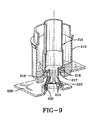
次に図9を参照するに、泡ポンプを分与器内に接続する、フレキシブルな機構の第3の実施形態が示されている。上述した第2の実施形態と同様に、この接続部材の第3の実施形態は図3−図6に示されているフレキシブルな接続部材に代えて詰め替えユニット20に用いることができる。この第3の実施形態において、大略円筒形の形状である分与器カップラ210は、ポンプ212の下方端のまわりに配置されている。複数の細長い、フレキシブルな延長部214が、ポンプ212の下方端に接続されていると共に、分与器カップラ210の下方端に設けた開口217を通して突出している。これらのフレキシブルな延長部214は、フレキシブルフィンガーとも称される。フレキシブルフィンガー214は、これらのフレキシブルフィンガー214がポンプ212から遠く離れて延びるにしたがって、互いから遠く離れるように自然に外向きにアーチしている。
Referring now to FIG. 9, a third embodiment of a flexible mechanism for connecting a foam pump into a dispenser is shown. Similar to the second embodiment described above, the third embodiment of the connection member can be used in the
円筒形のカラー216がフレキシブルフィンガー214のまわりに配置され、その結果、カラー216がフィンガー214の末端に位置させられると、フレキシブルフィンガー214は外向きにアーチすることが制限される。反対に、円筒形のカラー216が分与器カップラ210に隣接して位置させられると、フレキシブルフィンガー214は成形された形状のようにアーチすることができる。カラー216を分与器内に挿入する前に、カラー216はフレキシブルフィンガー214の末端に位置させられ、それらの外向きのアーチングを制限して挿入を容易にする。フレキシブルフィンガー214及びカラー216がハウジング内に挿入されると、これらのフィンガー及びカラーは、分与器カップラ210の底部の開口217を通過する。カラー216の外向きの延びているフランジ218は前記開口217のまわりの分与器カップラ210に当り、その結果、カラー216の円筒形本体は前記開口217内にとどまる。フレキシブルフィンガー214は、それから、ロックカラー216を通して滑動し、前記開口217を通して延びて、それらの自然の外向きのアーチング状態に戻る。フィンガー214がそれらの自然の形状に戻ると、これらのフィンガー214は駆動キャリッジ220の2つの円形リブ222間に受け入れられる。
A
当業者には認識されるように、上述した3つの実施形態の各々はフレキシブルな接続部材を包含し、これらの接続部材は、少なくとも一部分において変形することができる、それらの能力によって、ポンプを分与器ハウジング内に配置させることができる。フレキシブルな接続部材は、ポンプと駆動キャリッジとの間の接続を提供してインプット力をポンプへ伝え、これにより、泡を生成する。フレキシブルな接続部材の変形可能な弾性の性質は、もし駆動部材、例えば押し棒12が非常に大きな力でもって、駆動された場合には、減衰機能を提供する。同様に認識されるように、上述した各実施形態は分与器ハウジング内への詰め替えユニットの正確な取り付けを容易にする、信頼できる構成を提供する。
As will be appreciated by those skilled in the art, each of the three embodiments described above includes flexible connecting members, which separate the pump by their ability to be deformed at least in part. It can be placed in the container housing. The flexible connecting member provides a connection between the pump and the drive carriage to transmit input force to the pump, thereby generating bubbles. The deformable elastic nature of the flexible connecting member provides a dampening function if the drive member,
したがって、以上述べた構成の製品分与器は本発明の目的を達成し、この種の技術をかなり改善せしめることは明らかである。特許法の規定にしたがって最良で好適な実施形態についてのみ詳細に述べたけれども、本発明はこれらの実施形態についての記載により限定されるものではない。本発明の真の範囲を認識するためには、特許請求の範囲の記載を参照すべきである。 Therefore, it is clear that the product dispenser having the above-described configuration achieves the object of the present invention and considerably improves this kind of technology. Although only the best and preferred embodiments have been described in detail in accordance with the provisions of the patent law, the present invention is not limited to the description of these embodiments. To recognize the true scope of the present invention, reference should be made to the appended claims.
Claims (20)
内部空どうを画定する分与器ハウジングであって、この分与器ハウジングに枢動可能に接続されている駆動装置を有している分与器ハウジングと、
この分与器ハウジングの前記内部空どう内に配置されて、前記駆動装置に移動可能に係合されている駆動キャリッジと、
製品リザーバとポンプとを包含し、前記ポンプが前記製品リザーバに流体連通している詰め替えユニットと、
前記ポンプに取り付けられて前記ポンプから延びていると共に、前記駆動キャリッジにより受け入れられている、フレキシブルな接続部材と、
を包含し、
前記駆動装置の動きにより生じた前記駆動キャリッジの動きが前記フレキシブルな接続部材により前記ポンプに伝達されるようにした製品分与装置。 In product dispensing equipment,
A dispenser housing defining an internal cavity, the dispenser housing having a drive device pivotally connected to the dispenser housing;
A drive carriage disposed within the internal cavity of the dispenser housing and movably engaged with the drive device;
A refill unit including a product reservoir and a pump, wherein the pump is in fluid communication with the product reservoir;
A flexible connecting member attached to and extending from the pump and received by the drive carriage;
Including
The product dispensing device, wherein the movement of the drive carriage caused by the movement of the drive device is transmitted to the pump by the flexible connecting member.
溝を画定する一対の同心の円形リブを有する駆動キャリッジを用意し、また、
ポンプであって、このポンプから延びている、フレキシブルな接続部材を有するポンプを用意し、更に、
底面に設けた開口を有し、前記底面が前記開口に向かって内向きに傾斜しているロックリングを製品分与器内に設け、それから、
前記ポンプを前記製品分与器内に挿入し、これにより、前記フレキシブルな接続部材が前記底面の前記開口を通過するときに、前記フレキシブルな接続部材が変形するように付勢され、
前記フレキシブルな接続部材が前記ロックリングの前記開口を通過した後は、前記フレキシブルな接続部材がその元の形状に戻ることができて、前記駆動キャリッジに受け入れられるようにした方法。 In a method of connecting a pump to a drive carriage of a product dispenser,
Providing a drive carriage having a pair of concentric circular ribs defining a groove;
Providing a pump having a flexible connecting member extending from the pump;
A lock ring is provided in the product dispenser having an opening provided in the bottom surface, the bottom surface being inclined inwardly toward the opening;
Inserting the pump into the product dispenser, thereby biasing the flexible connecting member to deform when the flexible connecting member passes through the opening in the bottom surface;
After the flexible connecting member has passed through the opening of the lock ring, the flexible connecting member can return to its original shape and be received by the drive carriage.
Applications Claiming Priority (3)
| Application Number | Priority Date | Filing Date | Title |
|---|---|---|---|
| US19173908P | 2008-09-11 | 2008-09-11 | |
| US61/191,739 | 2008-09-11 | ||
| PCT/US2009/056648 WO2010030870A2 (en) | 2008-09-11 | 2009-09-11 | Pump having a flexible mechanism for engagement with a dispenser |
Publications (3)
| Publication Number | Publication Date |
|---|---|
| JP2012501927A JP2012501927A (en) | 2012-01-26 |
| JP2012501927A5 JP2012501927A5 (en) | 2012-11-01 |
| JP5404794B2 true JP5404794B2 (en) | 2014-02-05 |
Family
ID=41354112
Family Applications (1)
| Application Number | Title | Priority Date | Filing Date |
|---|---|---|---|
| JP2011526989A Expired - Fee Related JP5404794B2 (en) | 2008-09-11 | 2009-09-11 | Refill unit for use in a product dispensing device, product dispensing device and method for connecting a pump to a drive carriage of a product dispenser |
Country Status (14)
| Country | Link |
|---|---|
| US (1) | US8668116B2 (en) |
| EP (2) | EP2669016B1 (en) |
| JP (1) | JP5404794B2 (en) |
| KR (1) | KR20110058876A (en) |
| CN (1) | CN102186599B (en) |
| AU (1) | AU2009291708B2 (en) |
| BR (1) | BRPI0918484A2 (en) |
| CA (1) | CA2736123C (en) |
| DK (1) | DK2328690T3 (en) |
| ES (1) | ES2529058T3 (en) |
| HK (1) | HK1152269A1 (en) |
| PT (1) | PT2328690E (en) |
| TW (1) | TWI483780B (en) |
| WO (1) | WO2010030870A2 (en) |
Cited By (1)
| Publication number | Priority date | Publication date | Assignee | Title |
|---|---|---|---|---|
| US11883835B2 (en) | 2016-12-22 | 2024-01-30 | Conopco, Inc. | Shell container suitable for housing a discrete refill container |
Families Citing this family (44)
| Publication number | Priority date | Publication date | Assignee | Title |
|---|---|---|---|---|
| US8413852B2 (en) * | 2008-12-08 | 2013-04-09 | Gotohti.Com Inc. | Ramped actuator for engagement flange on removable dispenser cartridge |
| WO2011133077A1 (en) * | 2010-04-22 | 2011-10-27 | Sca Hygiene Products Ab | Pump soap dispenser |
| US8988228B2 (en) * | 2012-04-03 | 2015-03-24 | Swipesense, Inc. | Electronic module for tracking hand hygiene |
| US9340337B2 (en) | 2012-05-01 | 2016-05-17 | Ecolab Usa Inc. | Dispenser with lockable pushbutton |
| US8851331B2 (en) | 2012-05-04 | 2014-10-07 | Ecolab Usa Inc. | Fluid dispensers with adjustable dosing |
| US20130320043A1 (en) * | 2012-05-30 | 2013-12-05 | Gojo Industries, Inc. | Double acting valve for liquid pumps |
| US20140124540A1 (en) * | 2012-11-07 | 2014-05-08 | Gojo Industries, Inc. | Under-counter mount foam dispensing systems with permanent air compressors and refill units for same |
| US9266134B2 (en) | 2012-12-11 | 2016-02-23 | Gojo Industries, Inc. | Vented check valves, pumps and refill units with vented check valves |
| US9296508B2 (en) | 2012-12-13 | 2016-03-29 | Gojo Industries, Inc. | Collapsible containers and refill units |
| US8991655B2 (en) | 2013-02-15 | 2015-03-31 | Ecolab Usa Inc. | Fluid dispensers with increased mechanical advantage |
| US20150053720A1 (en) * | 2013-08-23 | 2015-02-26 | Gojo Industries, Inc. | Dispenser having top loading and unloading refill units |
| US20150250908A1 (en) * | 2014-03-10 | 2015-09-10 | Christopher Arnold Maupin | Intigrated Vehicle Hand Sanitizer |
| MY186715A (en) | 2014-10-02 | 2021-08-12 | Unilever Plc | Liquid dispenser with framed refill receiving bay |
| US10022023B2 (en) * | 2015-04-07 | 2018-07-17 | Vi-Jon, Inc. | Dispenser assembly |
| USD841073S1 (en) | 2015-06-04 | 2019-02-19 | Parabit Systems, Inc. | Surveillance camera enclosure |
| US9949599B2 (en) | 2015-06-17 | 2018-04-24 | Gojo Industries, Inc. | Vent valves and refill units with vent valves for use with inverted non-collapsing containers |
| US10034585B2 (en) * | 2015-08-05 | 2018-07-31 | Gojo Industries, Inc. | Pumps with restrictor-based lost motion |
| CN108136422B (en) | 2015-09-25 | 2021-10-29 | 易希提卫生与保健公司 | Pump for dispensing fluids |
| WO2017050392A1 (en) | 2015-09-25 | 2017-03-30 | Sca Hygiene Products Ab | Pump with a polymer spring |
| US10034583B2 (en) | 2016-03-04 | 2018-07-31 | Gpcp Ip Holdings Llc | Dispenser with stroke adjustment capabilities |
| USD806435S1 (en) * | 2016-05-27 | 2018-01-02 | Vi-Jon, Inc. | Dispenser assembly |
| USD811770S1 (en) * | 2016-06-21 | 2018-03-06 | Gojo Industries, Inc. | Wall mounted dispenser cabinet |
| USD824693S1 (en) * | 2016-08-24 | 2018-08-07 | Vi-Jon, Inc. | Dispenser assembly |
| USD862112S1 (en) | 2016-09-21 | 2019-10-08 | Gojo Industries, Inc. | Dispenser |
| USD815457S1 (en) | 2016-10-31 | 2018-04-17 | Gojo Industries, Inc. | Wall mounted dispenser cabinet |
| USD809821S1 (en) | 2016-10-31 | 2018-02-13 | Gojo Industries, Inc. | Wall mounted dispenser cabinet |
| US10278549B1 (en) | 2016-10-31 | 2019-05-07 | Gpcp Ip Holdings Llc | Counter-mounted skincare product dispenser |
| USD820614S1 (en) | 2016-11-28 | 2018-06-19 | Gojo Industries, Inc. | Wall mounted dispenser cabinet |
| USD826720S1 (en) | 2016-12-22 | 2018-08-28 | Conopco, Inc. | Bottle |
| USD830840S1 (en) | 2016-12-22 | 2018-10-16 | Conopco, Inc. | Container |
| AU2017406105B2 (en) | 2017-03-29 | 2021-07-22 | Essity Hygiene And Health Aktiebolag | Plastomer spring with captive valve |
| US10293353B2 (en) | 2017-04-25 | 2019-05-21 | Gpcp Ip Holdings Llc | Automated flowable material dispensers and related methods for dispensing flowable material |
| USD887477S1 (en) | 2018-01-12 | 2020-06-16 | Parabit Systems, Inc. | Surveillance camera enclosure |
| US10761409B2 (en) | 2018-01-12 | 2020-09-01 | Parabit Systems, Inc. | Surveillance camera enclosure |
| USD870791S1 (en) * | 2018-06-26 | 2019-12-24 | Parabit Systems, Inc. | Surveillance camera enclosure |
| US11027909B2 (en) | 2018-08-15 | 2021-06-08 | Gpcp Ip Holdings Llc | Automated flowable material dispensers and related methods for dispensing flowable material |
| RU190573U1 (en) * | 2018-12-14 | 2019-07-04 | Евгений Александрович Непокульчицкий | Dosing device |
| USD896865S1 (en) | 2018-12-26 | 2020-09-22 | Parabit Systems, Inc. | Surveillance camera enclosure |
| USD896864S1 (en) | 2018-12-26 | 2020-09-22 | Parabit Systems, Inc. | Surveillance camera enclosure |
| US10821458B2 (en) * | 2019-03-04 | 2020-11-03 | Hydro Systems Europe Ltd. | Liquid dispensing device |
| US11910982B2 (en) * | 2019-11-01 | 2024-02-27 | Conopco Inc. | Recyclable auto-dosing container |
| USD992635S1 (en) | 2021-08-02 | 2023-07-18 | Parabit Systems, Inc. | Surveillance camera enclosure |
| US11744413B2 (en) | 2021-10-07 | 2023-09-05 | Deb Ip Limited | Dispenser assembly |
| US11744412B2 (en) | 2021-10-07 | 2023-09-05 | Deb Ip Limited | Dispenser system |
Family Cites Families (25)
| Publication number | Priority date | Publication date | Assignee | Title |
|---|---|---|---|---|
| FR2315018A1 (en) | 1975-06-18 | 1977-01-14 | Broilliard Bernard | Paste or liq. distributor pump - has hollow piston with button sliding in body at base of reservoir |
| US4854484A (en) * | 1987-01-28 | 1989-08-08 | Chesebrough-Pond's Inc. | Viscous product dispenser |
| US4809878A (en) * | 1987-01-28 | 1989-03-07 | Chesebrough-Pond's Inc. | Pump dispenser for viscous fluids |
| US4928856A (en) * | 1987-03-11 | 1990-05-29 | White Jonathan Z | Bottled water dispensing system |
| US4979648A (en) * | 1989-07-31 | 1990-12-25 | Sunbeam Plastics Corporation | Child resistant push-pull dispensing closure |
| US5282552A (en) * | 1991-05-20 | 1994-02-01 | Hygiene-Technik Inc. | Disposable plastic liquid pump |
| US5165577A (en) * | 1991-05-20 | 1992-11-24 | Heiner Ophardt | Disposable plastic liquid pump |
| US5217433A (en) * | 1991-05-24 | 1993-06-08 | Merck & Co., Inc. | Medication container for mixing two components |
| USD351991S (en) * | 1993-06-01 | 1994-11-01 | Chesebrough-PondUSA Co., Division of Conopco, Inc. | Lotion dispensing bottle |
| CA2102016C (en) * | 1993-10-29 | 1995-08-15 | Heiner Ophardt | Liquid soap dispenser for simplified replacement of soap reservoir |
| ES2158353T3 (en) * | 1995-10-23 | 2001-09-01 | Unilever Nv | LIQUID DISPENSER. |
| US5826755A (en) * | 1995-12-18 | 1998-10-27 | Koller Enterprises, Inc. | Liquid dispenser with selectably attachable actuator |
| US5842441A (en) * | 1996-08-26 | 1998-12-01 | Pharmalett Denmark A/S | Medicated and individualized treatment shampoo for dermatological disturbances of companion animals |
| US6068162A (en) * | 1999-02-18 | 2000-05-30 | Avmor Ltd. | Adjustable soap dispenser |
| US6543649B1 (en) * | 2002-04-12 | 2003-04-08 | Saint-Gobain Calmar Inc. | Child-resistant liquid dispenser |
| FR2854821B1 (en) * | 2003-05-16 | 2006-12-08 | Oreal | ASSEMBLY FOR PACKAGING AND DISPENSING A PRODUCT, IN PARTICULAR IN THE FORM OF A SAMPLE |
| US7503465B2 (en) * | 2003-10-25 | 2009-03-17 | Joseph S. Kanfer | Universal adapter clip |
| US7278554B2 (en) * | 2004-05-10 | 2007-10-09 | Chester Labs, Inc. | Hinged dispenser housing and adaptor |
| CN101218166B (en) * | 2004-11-29 | 2011-08-17 | 西奎斯特完美分配器外国公司 | Dispenser with lock |
| US7201295B1 (en) * | 2004-12-16 | 2007-04-10 | Sitzberger Carl R | Fitment assembly for a liquid dispenser |
| CA2863738C (en) * | 2007-06-22 | 2016-04-26 | Op-Hygiene Ip Gmbh | Split engagement flange for soap dispenser pump piston |
| US8047404B2 (en) * | 2008-02-08 | 2011-11-01 | Gojo Industries, Inc. | Bifurcated stem foam pump |
| ATE490714T1 (en) * | 2008-05-29 | 2010-12-15 | Gojo Ind Inc | PULL POWERED FOAM PUMP |
| CA2645953A1 (en) * | 2008-12-08 | 2010-06-08 | Gotohti.Com Inc. | Engagement flange for fluid dispenser pump piston |
| US8113388B2 (en) * | 2008-12-08 | 2012-02-14 | Heiner Ophardt | Engagement flange for removable dispenser cartridge |
-
2009
- 2009-09-10 TW TW098130561A patent/TWI483780B/en not_active IP Right Cessation
- 2009-09-11 BR BRPI0918484A patent/BRPI0918484A2/en not_active IP Right Cessation
- 2009-09-11 KR KR1020117008101A patent/KR20110058876A/en not_active Application Discontinuation
- 2009-09-11 ES ES09792459.1T patent/ES2529058T3/en active Active
- 2009-09-11 WO PCT/US2009/056648 patent/WO2010030870A2/en active Application Filing
- 2009-09-11 CN CN200980135542.7A patent/CN102186599B/en not_active Expired - Fee Related
- 2009-09-11 DK DK09792459.1T patent/DK2328690T3/en active
- 2009-09-11 EP EP13182161.3A patent/EP2669016B1/en active Active
- 2009-09-11 JP JP2011526989A patent/JP5404794B2/en not_active Expired - Fee Related
- 2009-09-11 PT PT09792459T patent/PT2328690E/en unknown
- 2009-09-11 EP EP09792459.1A patent/EP2328690B1/en active Active
- 2009-09-11 AU AU2009291708A patent/AU2009291708B2/en not_active Ceased
- 2009-09-11 CA CA2736123A patent/CA2736123C/en active Active
- 2009-09-11 US US12/557,978 patent/US8668116B2/en active Active
-
2011
- 2011-06-16 HK HK11106222.4A patent/HK1152269A1/en not_active IP Right Cessation
Cited By (1)
| Publication number | Priority date | Publication date | Assignee | Title |
|---|---|---|---|---|
| US11883835B2 (en) | 2016-12-22 | 2024-01-30 | Conopco, Inc. | Shell container suitable for housing a discrete refill container |
Also Published As
| Publication number | Publication date |
|---|---|
| HK1152269A1 (en) | 2012-02-24 |
| US20100059550A1 (en) | 2010-03-11 |
| WO2010030870A3 (en) | 2010-05-14 |
| ES2529058T3 (en) | 2015-02-16 |
| AU2009291708A1 (en) | 2010-03-18 |
| CN102186599A (en) | 2011-09-14 |
| KR20110058876A (en) | 2011-06-01 |
| TWI483780B (en) | 2015-05-11 |
| CA2736123A1 (en) | 2010-03-18 |
| TW201029745A (en) | 2010-08-16 |
| WO2010030870A2 (en) | 2010-03-18 |
| CA2736123C (en) | 2016-08-30 |
| DK2328690T3 (en) | 2015-03-30 |
| EP2328690A2 (en) | 2011-06-08 |
| EP2328690B1 (en) | 2015-01-14 |
| AU2009291708B2 (en) | 2014-10-23 |
| EP2669016B1 (en) | 2019-04-17 |
| BRPI0918484A2 (en) | 2015-12-01 |
| CN102186599B (en) | 2014-01-15 |
| US8668116B2 (en) | 2014-03-11 |
| JP2012501927A (en) | 2012-01-26 |
| EP2669016A1 (en) | 2013-12-04 |
| PT2328690E (en) | 2015-03-11 |
Similar Documents
| Publication | Publication Date | Title |
|---|---|---|
| JP5404794B2 (en) | Refill unit for use in a product dispensing device, product dispensing device and method for connecting a pump to a drive carriage of a product dispenser | |
| JP2012501927A5 (en) | ||
| EP2731486B1 (en) | Shut-off system for a dispenser | |
| JP5330715B2 (en) | Dispenser | |
| US8245881B2 (en) | Spring force adjustment system | |
| EP2099707B1 (en) | Device for discharge or outfeed | |
| AU2006212195B2 (en) | Dispenser | |
| JP2008237904A5 (en) | ||
| US20070075096A1 (en) | Blister pump dispenser | |
| US9199834B2 (en) | Dispensing device | |
| US9730538B2 (en) | Surface tension condiment dispenser | |
| US20090127285A1 (en) | Dispensing device | |
| JP2010504852A (en) | Liquid dispenser device | |
| JP2008230619A (en) | Pump container operable with single hand | |
| US9565977B2 (en) | Dispensers and refill units having collapsible outlet tubes | |
| US9694374B2 (en) | Suck-back liquid dispensing valve and valve assembly | |
| JP2020513278A (en) | Operation mechanism of manual dispenser | |
| JP2010172858A (en) | Liquid spouting device with lever | |
| EP2711087A2 (en) | Dosage pump and dosage system |
Legal Events
| Date | Code | Title | Description |
|---|---|---|---|
| A521 | Request for written amendment filed |
Free format text: JAPANESE INTERMEDIATE CODE: A523 Effective date: 20120911 |
|
| A621 | Written request for application examination |
Free format text: JAPANESE INTERMEDIATE CODE: A621 Effective date: 20120911 |
|
| A977 | Report on retrieval |
Free format text: JAPANESE INTERMEDIATE CODE: A971007 Effective date: 20130827 |
|
| TRDD | Decision of grant or rejection written | ||
| A01 | Written decision to grant a patent or to grant a registration (utility model) |
Free format text: JAPANESE INTERMEDIATE CODE: A01 Effective date: 20131008 |
|
| A61 | First payment of annual fees (during grant procedure) |
Free format text: JAPANESE INTERMEDIATE CODE: A61 Effective date: 20131029 |
|
| R150 | Certificate of patent or registration of utility model |
Ref document number: 5404794 Country of ref document: JP Free format text: JAPANESE INTERMEDIATE CODE: R150 |
|
| R250 | Receipt of annual fees |
Free format text: JAPANESE INTERMEDIATE CODE: R250 |
|
| R250 | Receipt of annual fees |
Free format text: JAPANESE INTERMEDIATE CODE: R250 |
|
| R250 | Receipt of annual fees |
Free format text: JAPANESE INTERMEDIATE CODE: R250 |
|
| R250 | Receipt of annual fees |
Free format text: JAPANESE INTERMEDIATE CODE: R250 |
|
| R250 | Receipt of annual fees |
Free format text: JAPANESE INTERMEDIATE CODE: R250 |
|
| R250 | Receipt of annual fees |
Free format text: JAPANESE INTERMEDIATE CODE: R250 |
|
| LAPS | Cancellation because of no payment of annual fees |