JP5404371B2 - Video display device, control method therefor, and program - Google Patents
Video display device, control method therefor, and program Download PDFInfo
- Publication number
- JP5404371B2 JP5404371B2 JP2009288468A JP2009288468A JP5404371B2 JP 5404371 B2 JP5404371 B2 JP 5404371B2 JP 2009288468 A JP2009288468 A JP 2009288468A JP 2009288468 A JP2009288468 A JP 2009288468A JP 5404371 B2 JP5404371 B2 JP 5404371B2
- Authority
- JP
- Japan
- Prior art keywords
- display
- area
- display frame
- video display
- video
- Prior art date
- Legal status (The legal status is an assumption and is not a legal conclusion. Google has not performed a legal analysis and makes no representation as to the accuracy of the status listed.)
- Active
Links
Images


Description
本発明は、映像を表示する映像表示領域以外の領域を照明装置として使用する映像表示装置に係わる。 The present invention relates to a video display device that uses a region other than a video display region for displaying a video as a lighting device.
ディスプレイは発光素子であるので、ディスプレイを照明として利用することが考えられる。ディスプレイを照明として使用する製品として、例えば、非特許文献1が掲示しているKyouei design社の「COLOR LIGHT」が挙げられる。ただし、この「COLOR LIGHT」は、ディスプレイを照明としてのみ使用する。 Since the display is a light emitting element, it is conceivable to use the display as illumination. As a product that uses a display as illumination, for example, “COLOR LIGHT” of Kyoei design, which is disclosed in Non-Patent Document 1, can be mentioned. However, this “COLOR LIGHT” uses the display only as illumination.
近年、LEDアレイによる大型ディスプレイ、低価格有機EL、ガラスチューブとフィルム電極を用いた大型プラズマディスプレイなどが開発され、部屋内の壁面を大型ディスプレイで構成する事が現実的になりつつある。また、一方、LED、有機ELなどは、その発光効率の良さから、白熱電球に代わり、部屋内照明の一手段として使われつつある。また、ディスプレイを用い映像を鑑賞する場合には、室内の照明を暗く設定する事は、特に映画の鑑賞時などには一般的におこなわれている。 In recent years, large-scale displays using LED arrays, low-cost organic EL, large-sized plasma displays using glass tubes and film electrodes, and the like have been developed, and it is becoming realistic to configure the walls in the room with large-sized displays. On the other hand, LEDs, organic EL, and the like are being used as a means of in-room lighting instead of incandescent bulbs because of their good luminous efficiency. In addition, when viewing images using a display, setting indoor lighting to dark is generally performed especially when watching movies.
上記を背景とし、LED、有機ELなどで実現された大型のディスプレイを映像表示と照明に兼用するアイディアが提案されている。ディスプレイで室内を照明しながら、映像を鑑賞する場合には、ディスプレイの一部に映像を表示すると同時に、その周囲部を用いて室内を照明する使用形態となる。 With the above as a background, an idea has been proposed in which a large display realized by an LED, an organic EL, or the like is used for both video display and illumination. When viewing an image while illuminating the room with a display, the image is displayed on a part of the display, and at the same time, the surrounding area is used to illuminate the room.
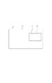
しかし、ディスプレイを同時に映像表示と照明の用途に使用すると以下に述べるような課題が生じる。図2にディスプレイを同時に映像表示と照明の用途に使用する例を示す。図2において、表示面31上に映像表示領域32と照明領域33が存在する。映像表示領域32に映像を表示し、それ以外の領域である照明領域33を用いて部屋内を照明する。
However, if the display is simultaneously used for video display and illumination, the following problems arise. FIG. 2 shows an example in which the display is simultaneously used for video display and illumination. In FIG. 2, a
人の視覚特性は、瞳孔を開閉し輝度差を最も良く感じることができる領域を、より明るく発光する領域に合わせる。したがって、図2において、照明領域33が常に映像表示領域32より明るく発光すると、人の視覚特性により、瞳孔を開閉し輝度差を最も良く感じることができる領域を照明領域33に合わせてしまう。そのため、映像表示領域32の輝度差が判別できなくなってしまう。その結果、映像を好適に鑑賞できない、あるいは映像から得るべき必要な情報が得られない、という課題があった。
The visual characteristics of a person match the area where the luminance difference is best felt by opening and closing the pupil to the area that emits light more brightly. Therefore, in FIG. 2, if the illumination area 33 always emits light brighter than the
本発明は上述した課題を解決するためになされたものであり、好適な映像表示と部屋内照明を同時に実現することを目的とする。 The present invention has been made to solve the above-described problems, and an object thereof is to simultaneously realize a suitable video display and in-room lighting.
上述の問題点を解決するため、本発明の画像表示装置は以下の構成を備える。すなわち、映像を表示する映像表示領域以外の領域を照明装置として使用する映像表示装置であって、前記映像表示領域の周囲に、映像表示領域としても照明装置としても使用しない表示枠を形成する手段と、前記映像表示領域と前記形成した表示枠を合成する手段と、前記照明装置として使用する領域の動作を制御する手段と、前記表示枠と合成した映像表示領域と前記照明装置として使用する領域を合成する手段とを具備したことを特徴とする。 In order to solve the above-described problems, the image display apparatus of the present invention has the following configuration. That is, a video display device that uses a region other than a video display region for displaying a video as a lighting device, and means for forming a display frame that is not used as a video display region or a lighting device around the video display region Means for synthesizing the image display area and the formed display frame, means for controlling the operation of the area used as the illumination device, an image display area synthesized with the display frame, and an area used as the illumination device. And a means for synthesizing.
表示枠の作用により、好適な映像表示と部屋内照明を同時に実現することが可能となる。 Due to the action of the display frame, it is possible to simultaneously realize suitable video display and in-room lighting.
さらに、映像表示領域の大きさを検出することにより、表示枠の幅を手動で調整する手間を省くことが可能になる。また、視聴者までの距離を検出することにより、表示枠の幅を手動で調整する手間を省くことが可能になる。また、表示する映像の内容を事前に検出する事により、映像の内容に合わせた表示枠の幅を手動で調整する手間を省くことができる。また、照明領域の輝度を検出する事により、表示枠の幅を手動で調整する手間を省くことができる。 Furthermore, by detecting the size of the video display area, it is possible to save the trouble of manually adjusting the width of the display frame. Further, by detecting the distance to the viewer, it is possible to save the trouble of manually adjusting the width of the display frame. Further, by detecting the content of the video to be displayed in advance, it is possible to save the trouble of manually adjusting the width of the display frame according to the content of the video. Further, by detecting the luminance of the illumination area, it is possible to save the trouble of manually adjusting the width of the display frame.
その上、部屋内の明るさと表示枠の幅を検出することにより、部屋内照度を一定に保つために照明領域の照度を手動で調整する手間を省く事ができる。 In addition, by detecting the brightness in the room and the width of the display frame, it is possible to save the trouble of manually adjusting the illuminance of the illumination area in order to keep the illuminance in the room constant.
また、ディスプレイ装置を照明にも兼用する本質的な利点として、ディスプレイと照明装置を別に設ける場合に比較し、低消費電力化、低価格化、利便性の向上などの効果がある。 Further, as an essential advantage of using the display device also for illumination, there are effects such as lower power consumption, lower cost, and improved convenience as compared with the case where the display and the illumination device are provided separately.
以下、添付の図面を参照して、本願発明をその好適な実施形態に基づいて詳細に説明する。なお、以下の実施形態において示す構成は一例に過ぎず、本発明は図示された構成に限定されるものではない。 Hereinafter, the present invention will be described in detail based on the preferred embodiments with reference to the accompanying drawings. The configurations shown in the following embodiments are merely examples, and the present invention is not limited to the illustrated configurations.
<実施形態1>
まず、本発明に係わる映像表示装置の機能を説明する。本発明に係わる映像表示装置は、部屋の壁とほぼ同じ大きさの表示面を有し、当該表示面を室内照明と映像表示に使用する。映像を表示していない時、当該表示面は全領域あるいは一部の領域を照明領域に充て、側方照明装置として発明に係わる映像表示装置を使用する。映像を表示する時は、当該表示面に、映像表示領域を設定し当該映像表示領域に映像を表示する。映像表示領域以外の領域は、その全てあるいは一部を照明領域に充て側方照明装置として使用する。図3に、本発明に係わる映像表示装置の、表示面31、映像表示領域32、照明領域33および表示枠34の関係の一実施例を示す。ここで、表示枠34は、映像表示領域32の周囲に設定した、映像表示領域にも照明領域にも使用しない部分である。表示枠34は、低輝度で発光するか、もしくは発光しない。
<Embodiment 1>
First, the function of the video display apparatus according to the present invention will be described. The video display apparatus according to the present invention has a display surface that is approximately the same size as the wall of the room, and uses the display surface for room lighting and video display. When an image is not displayed, the display surface covers the entire area or a part of the area as an illumination area, and the image display apparatus according to the invention is used as a side illumination apparatus. When displaying a video, a video display area is set on the display surface, and the video is displayed in the video display area. All or a part of the area other than the video display area is used as a side illumination device by allocating the entire or part of the illumination area. FIG. 3 shows an example of the relationship among the
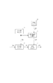
図1は実施形態1の画像表示装置を示す図である。本発明に係わる映像表示装置は、表示枠形成部11、表示枠合成部12、照明領域制御部13、および領域合成部14を少なくとも有している。
FIG. 1 is a diagram illustrating an image display apparatus according to the first embodiment. The video display apparatus according to the present invention includes at least a display frame forming unit 11, a display
表示枠形成部11の詳細を説明する。表示枠形成部11は、入力映像101および表示枠形成部11が測定・計測する諸元を基に、表示枠情報102を算出し、出力する。この表示枠情報102は、表示枠の幅(r)を少なくとも含む。
Details of the display frame forming unit 11 will be described. The display frame forming unit 11 calculates and outputs the
表示枠形成部11が有する表示枠形成方法を図7に示す。図7には、方法Aから方法Eの5種類の表示枠形成方法を挙げている。勿論、表示枠形成方法を図7に挙げた方法に限定するものではない。 A display frame forming method of the display frame forming unit 11 is shown in FIG. FIG. 7 shows five types of display frame forming methods, Method A to Method E. Of course, the display frame forming method is not limited to the method shown in FIG.
方法Aは、入力映像101や本発明に係わる表示装置周囲の環境に依存せず、表示枠の幅(r)は固定である。常に固定値の表示枠の幅(r)を表示枠情報102に出力する。
Method A does not depend on the
方法Bは、表示枠の幅(r)を映像表示領域32の大きさ(w)に依存して算出する。映像表示領域32の大きさ(w)と表示枠の幅(r)の間には、wが増加するとrは減少するという関係がある。
Method B calculates the width (r) of the display frame depending on the size (w) of the
しかし、映像表示領域32の大きさ(w)と最適な表示枠の幅(r)の関係は、表示面31の大きさや最大輝度により異なり、一意ではない。そこで、予め複数の映像表示領域32の大きさ(w)ごとに、表示枠(r)の大きさを変化させ、最も見やすい表示枠(r)の大きさを求めておく。この結果から、映像表示領域32の大きさ(w)と最適な表示枠の幅(r)の関係を表す関数f(w)を求める。
However, the relationship between the size (w) of the
そして、方法Bを選択したときには、この関数f(w)を用いて、表示枠の幅(r)を算出し、表示枠情報102に出力する。
When the method B is selected, the width (r) of the display frame is calculated using this function f (w) and output to the
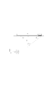
方法Cは、映像表示領域32が人間の視野より小さい場合、その差分領域を表示枠34で埋めるように、表表示枠の幅(r)を算出する。図5に、視聴者までの距離(d)、映像表示領域32の大きさ(w)、表示枠の幅(r)と人間の視野角θの関係を示す。図5に示すように、方法Cにおいて、表示枠の幅(r)を算出するためには、視聴者までの距離(d)、映像表示領域32の大きさ(w)と人間の視野角θが必要である。このうち、人間の視野角θは120度の固定値を使用する。勿論、視野角を120度に限定するものではない。
In the method C, when the
方法Cを選択したときには、測定・計測した視聴者までの距離(d)と映像表示領域32の大きさ(w)から以下式(1)を用いて、表示枠の幅(r)を算出し、表示枠情報102に出力する。
When Method C is selected, the display frame width (r) is calculated from the measured / measured distance (d) to the viewer and the size (w) of the
方法Dは、映像の内容(c)に依存して表示枠の幅(r)を算出する。しかし、映像の内容(c)と最適な表示枠の幅(r)の関係は、表示面31の大きさや最大輝度により異なり、一意ではない。そこで、予め映像の内容(c)ごとに、表示枠(r)の大きさを変化させ、最も見やすい表示枠(r)の大きさを求め、対応表の形にしておく。そして、方法Dを選択したときには、この対応表を参照して、表示枠の幅(r)を算出し、表示枠情報102に出力する。
Method D calculates the width (r) of the display frame depending on the content (c) of the video. However, the relationship between the video content (c) and the optimal display frame width (r) varies depending on the size of the
方法Eは、照明領域の輝度(l)に依存して表示枠の幅(r)を算出する。照明領域の輝度(l)と表示枠の幅(r)の間には、lが増加するとrは増加するという関係がある。 Method E calculates the width (r) of the display frame depending on the luminance (l) of the illumination area. Between the luminance (l) of the illumination area and the width (r) of the display frame, there is a relationship that r increases as l increases.
しかし、照明領域の輝度(l)と最適な表示枠の幅(r)の関係は、表示面31の大きさや最大輝度により異なり、一意ではない。そこで、予め複数の照明領域の輝度(l)ごとに、表示枠(r)の大きさを変化させ、最も見やすい表示枠(r)の大きさを求めておく。この結果から、照明領域の輝度(l)と最適な表示枠の幅(r)の関係を表す関数g(l)を求める。
However, the relationship between the luminance (l) of the illumination area and the optimum width (r) of the display frame varies depending on the size of the
そして、方法Eを選択したときには、この関数g(l)を用いて、表示枠の幅(r)を算出し、表示枠情報102に出力する。
When the method E is selected, the function g (l) is used to calculate the display frame width (r) and output it to the
表示枠34を設定すると、その面積だけ照明領域33の面積が減少し、照度が低下する。しかし、表示枠34の面積は表示面31の面積に比較して小さく、そのため照度の低下も無視できる。よって、方法Eを選択しても照度の補正は実施しないとする。勿論、照度の補正の実施を妨げるものではない。
When the
本発明は、測定・計測する諸元の測定・計測手段に依存したものではない。したがって、公知の技術を用いて、各諸元を測定・計測してよい。例えば、視聴者までの距離(d)を測定・計測する手段として、表示装置のリモートコントローラに応答器を設けておき、表示装置から信号を送信し応答器が応答した信号を表示装置が受信するまでの時間から求める手段が使用できる。また、照明領域の輝度(l)の測定・計測には、本発明に係わる映像表示装置が設置された部屋の各所に光センサを設置し、その光センサで照明領域の輝度を測定・計測する手段が使用できる。勿論、各諸元の測定・計測手段を上記例に限定するものではない。 The present invention does not depend on the measurement / measurement means of the items to be measured / measured. Therefore, each specification may be measured and measured using a known technique. For example, as a means for measuring / measuring the distance (d) to the viewer, a responder is provided in the remote controller of the display device, and the display device receives a signal transmitted from the display device and responded by the responder. The means to obtain from the time until can be used. For measuring and measuring the luminance (l) of the illumination area, an optical sensor is installed in each part of the room where the video display apparatus according to the present invention is installed, and the luminance of the illumination area is measured and measured by the optical sensor. Means can be used. Of course, the measurement / measurement means for each item is not limited to the above example.
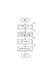
図4に、表示枠形成部11が表示枠情報102を形成するフローチャートを示す。図4を使用して、表示枠形成部11が表示枠情報102を形成する手順を説明する。
FIG. 4 shows a flowchart in which the display frame forming unit 11 forms the
ステップS001で、表示枠形成に使用する方法を視聴者が選択する。選択部は、例えば、表示装置のリモートコントローラの使用が挙げられる。勿論、選択部をリモートコントローラの使用に限定するものではない。ステップS001で表示枠形成に使用する方法を選択したならば、ステップS002で、選択した表示枠形成方法が使用する枠形成に必要な情報を測定・計測する。 In step S001, the viewer selects a method used for display frame formation. An example of the selection unit is the use of a remote controller of a display device. Of course, the selection unit is not limited to the use of a remote controller. If a method used for display frame formation is selected in step S001, information necessary for frame formation used by the selected display frame formation method is measured and measured in step S002.
ステップS003で、選択した表示枠形成方法を用いて表示枠の幅(r)を決定し、ステップS004で表示枠情報102として出力する。
In step S003, the width (r) of the display frame is determined using the selected display frame forming method, and the
次に、表示枠合成部12の動作を説明する。表示枠合成部12は、表示枠形成部11で形成した表示枠情報102を用いて、形成した表示枠と映像を合成する。合成する映像は、映像処理済みの映像である。
Next, the operation of the display
表示枠の幅(r)の表示枠を形成できないならば、表示枠合成部12は次のように動作する。まず、表示枠の幅(r)の表示枠を形成できない例として、映像表示領域32の下辺と表示面31の下辺との間隔が、表示枠の幅(r)未満の場合を取り上げる。この例を用いて、表示枠合成部12の動作を説明する。このとき、映像表示領域32の周囲に、rの幅を持つ表示枠を形成することはできない。そこで、上辺、左辺および右辺はrの幅を持ち、表示枠の下辺の幅は映像表示領域32の下辺と表示面31の下辺との間隔とする表示枠を形成する。
If a display frame having the width (r) of the display frame cannot be formed, the display
照明領域制御部13は、照明領域33の照度を制御する照明領域制御信号104を生成する。使用者が、照明領域33を点灯し、あるいは消灯する操作、あるいは、照明領域33の照度を変える操作は、この照明領域制御部13が処理する。勿論、照明領域制御部13の処理を上記例に限定するものではない。照明領域制御信号104の仕様は表示装置の仕様に依存する。ただし、少なくとも照明領域制御信号104は表示面31を照明装置として使用するのに必要な情報を含む。
The illumination
領域合成部14は、表示枠合成部の出力103と照明領域制御信号104から、表示装置の入力105を生成する。このとき、表示枠合成部の出力103が示す、表示枠附きの映像表示領域を、照明領域33に優先させて、表示装置の入力105を生成する。
The
<実施形態2>
次に本発明に係わる映像表示装置の実施形態2を説明する。今、映像表示領域32と表示枠34を設定し、図3に示す状態になったとする。
<Embodiment 2>
Next, Embodiment 2 of the video display apparatus according to the present invention will be described. Now, assume that the
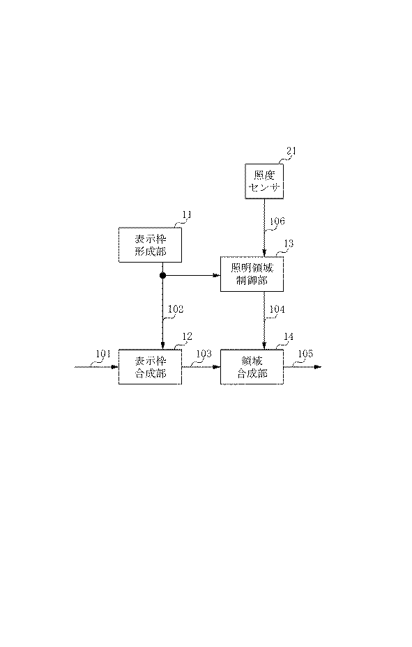
図6は本発明の実施形態2を示す図である。実施形態1に対して、本発明に係わる表示装置を設置した部屋の照度を計測する照度センサ21を加えている。さらに、照明領域制御部13に、照度センサの出力106と表示枠情報102を加えている。
FIG. 6 is a diagram showing Embodiment 2 of the present invention. An illuminance sensor 21 that measures the illuminance of the room in which the display device according to the present invention is installed is added to the first embodiment. Further, an
本発明は、照度センサ21に依存したものではない。したがって、公知の技術で照度センサ21を構成してよい。例えば、フォトダイオードを用いて、照度センサ21を構成することが可能である。また、本発明は、照度センサ21の個数や配置に依存したものではない。したがって、発明に係わる表示装置を設置した部屋の照度が計測できれば、照度センサ21はどのように配置してもよい。 The present invention does not depend on the illuminance sensor 21. Therefore, you may comprise the illumination intensity sensor 21 with a well-known technique. For example, the illuminance sensor 21 can be configured using a photodiode. Further, the present invention does not depend on the number or arrangement of the illuminance sensors 21. Therefore, the illuminance sensor 21 may be arranged in any way as long as the illuminance of the room in which the display device according to the invention is installed can be measured.
次に、本実施形態における照明領域制御部13の詳細を説明する。照明領域制御部13は、映像表示領域32と表示枠34を設定したことで生じた部屋の照度低下を補償する方法を図8に示す。勿論、図8に示す補償方法に限定するものではない。
Next, details of the illumination
照明領域の単位面積あたりの輝度(lu)は、予め測定するか、あるいは仕様から算出しておく。映像表示領域32と表示枠34の面積(ia)は、表示枠情報102から求める。映像表示領域32と表示枠34設定後の照明領域の面積をlaとする。laは、映像表示領域32と表示枠34設定前の照明領域の面積から、映像表示領域32と表示枠34の面積(ia)を減算すればよい。したがって、n組の映像表示領域32と表示枠34が設定されている場合の照明領域の面積(la)は、以下式(2)で表される。以下式(2)において、la0は表示面の面積、ia(k)は、k組目の映像表示領域32と表示枠34の面積である。
The luminance (lu) per unit area of the illumination area is measured in advance or calculated from specifications. The area (ia) of the
![]()
![]()
また、映像表示領域32と表示枠34設定前の部屋の照度をi0とし、映像表示領域32と表示枠34設定後の部屋の照度をi1とする。
Further, the illuminance of the room before setting the
方式Aでは、映像表示領域32と表示枠34を設定したことで減少する発光量(lu * ia)を、照明領域33に均等に割り当てる。したがって、照明領域33の単位面積あたり、以下式(3)に示す発光量を増加させる。
(lu*ia)/la ・・・(3)
方式Bは、映像表示領域32と表示枠34の設定前後で、照度センサの出力106から求めた部屋の照度が同じになるように、照明領域33を制御する。本発明は、制御理論に依存したものではない。したがって、既存の制御理論を用いて方式Bを構成可能である。
In the method A, the light emission amount (lu * ia) which decreases by setting the
(Lu * ia) / la (3)
In method B, the illumination area 33 is controlled so that the room illuminance obtained from the
方式Cは、方式Aと方式Bを合わせて使用する。輝度の低下量は、映像表示領域32と表示枠34の面積から容易に判明する。そこで、まず方式Aを適用して、部屋の照度を同じにする。しかし、経時劣化や、本発明に係わる映像表示装置を設置した部屋の特性に因り、誤差が生じることがある。この誤差を方式Bで補償する。
Method C uses method A and method B together. The amount of decrease in luminance is easily determined from the areas of the
図8に示す3方式全てを、本実施形態に係わる照明領域制御部13が実装する必要はない。方式Aのみ実装する場合、照度センサ21は不要である。また、方式Bのみ実装する場合、照明領域制御部13に表示枠情報102の入力は不要である。
It is not necessary for the illumination
<実施形態3>
図1、図6に示したそれぞれの装置が有する各部は全てハードウェアでもって構成しているものとして上記実施形態では説明した。しかし各部をコンピュータプログラムでもって構成しても良い。この場合、このようなコンピュータプログラムを格納するためのメモリと、このメモリに格納されているコンピュータプログラムを実行するCPUとを有するコンピュータは、上記各実施形態に係る画像表示装置に適用することができる。
<Embodiment 3>
The above embodiments have been described on the assumption that all the units included in the respective apparatuses shown in FIGS. 1 and 6 are configured by hardware. However, each unit may be configured by a computer program. In this case, a computer having a memory for storing such a computer program and a CPU for executing the computer program stored in the memory can be applied to the image display device according to each of the above embodiments. .
図9は、上記各実施形態に係る画像処理装置に適用可能なコンピュータのハードウェアの構成例を示すブロック図である。 FIG. 9 is a block diagram illustrating a configuration example of computer hardware applicable to the image processing apparatus according to each of the embodiments.
CPU901は、RAM902やROM903に格納されているコンピュータプログラムやデータを用いてコンピュータ全体の制御を行うと共に、上記各実施形態に係る画像処理装置が行うものとして上述した各処理を実行する。即ち、CPU901は、図1、図6の11〜14として機能することになる。
The
RAM902は、外部記憶装置906からロードされたコンピュータプログラムやデータ、I/F(インターフェース)909を介して外部から取得したデータなどを一時的に記憶するためのエリアを有する。更に、RAM902は、CPU901が各種の処理を実行する際に用いるワークエリアを有する。即ち、RAM902は、例えば、フレームメモリとして割当てたり、その他の各種のエリアを適宜提供することができる。
The
ROM903には、本コンピュータの設定データや、ブートプログラムなどが格納されている。操作部904は、キーボードやマウスなどにより構成されており、本コンピュータのユーザが操作することで、各種の指示をCPU901に対して入力することができる。表示部905は、CPU901による処理結果を表示する。また表示部905は例えば液晶ディスプレイのようなホールド型の表示装置や、フィールドエミッションタイプの表示装置のようなインパルス型の表示装置で構成される。
The
外部記憶装置906は、ハードディスクドライブ装置に代表される、大容量情報記憶装置である。外部記憶装置906には、OS(オペレーティングシステム)や、図1、図6に示した各部の機能及び図4に示したフローをCPU901に実現させるためのコンピュータプログラムが保存されている。更には、外部記憶装置906には、処理対象としての各画像データが保存されていても良い。
The
外部記憶装置906に保存されているコンピュータプログラムやデータは、CPU901による制御に従って適宜RAM902にロードされ、CPU901による処理対象となる。I/F907には、LANやインターネット等のネットワーク、他の機器を接続することができ、本コンピュータはこのI/F907を介して様々な情報を取得したり、送出したりすることができる。908は上述の各部を繋ぐバスである。
Computer programs and data stored in the
上述の構成からなる作動は前述のフローチャートで説明した作動をCPU901が中心となって行う。
In the operation having the above-described configuration, the
<その他の実施形態>
また、本発明の目的は、前述した機能を実現するコンピュータプログラムのコードを記録した記憶媒体を、システムに供給し、そのシステムがコンピュータプログラムのコードを読み出し実行することによっても達成される。この場合、記憶媒体から読み出されたコンピュータプログラムのコード自体が前述した実施形態の機能を実現し、そのコンピュータプログラムのコードを記憶した記憶媒体は本発明を構成する。また、そのプログラムのコードの指示に基づき、コンピュータ上で稼働しているオペレーティングシステム(OS)などが実際の処理の一部または全部を行い、その処理によって前述した機能が実現される場合も含まれる。
<Other embodiments>
The object of the present invention can also be achieved by supplying, to a system, a storage medium that records the code of a computer program that realizes the functions described above, and the system reads and executes the code of the computer program. In this case, the computer program code itself read from the storage medium realizes the functions of the above-described embodiments, and the storage medium storing the computer program code constitutes the present invention. In addition, the operating system (OS) running on the computer performs part or all of the actual processing based on the code instruction of the program, and the above-described functions are realized by the processing. .
さらに、以下の形態で実現しても構わない。すなわち、記憶媒体から読み出されたコンピュータプログラムコードを、コンピュータに挿入された機能拡張カードやコンピュータに接続された機能拡張ユニットに備わるメモリに書込む。そして、そのコンピュータプログラムのコードの指示に基づき、その機能拡張カードや機能拡張ユニットに備わるCPUなどが実際の処理の一部または全部を行って、前述した機能が実現される場合も含まれる。 Furthermore, you may implement | achieve with the following forms. That is, the computer program code read from the storage medium is written into a memory provided in a function expansion card inserted into the computer or a function expansion unit connected to the computer. Then, based on the instruction of the code of the computer program, the above-described functions are realized by the CPU or the like provided in the function expansion card or function expansion unit performing part or all of the actual processing.
本発明を上記記憶媒体に適用する場合、その記憶媒体には、先に説明したフローチャートに対応するコンピュータプログラムのコードが格納されることになる。 When the present invention is applied to the above storage medium, the computer program code corresponding to the flowchart described above is stored in the storage medium.
Claims (4)
前記映像表示領域の周囲に、映像表示領域としても照明装置としても使用しない表示枠を形成する手段と、
前記映像表示領域と前記形成した表示枠を合成する手段と、
前記照明装置として使用する領域の動作を制御する手段と、
前記表示枠と合成した映像表示領域と、照明装置として使用する領域を合成する手段とを
具備したことを特徴とする映像表示装置。 A video display device that uses an area other than the video display area for displaying video as a lighting device,
Means for forming a display frame that is not used as a video display area or a lighting device around the video display area;
Means for combining the video display area and the formed display frame;
Means for controlling the operation of the area used as the lighting device;
A video display device comprising: a video display region combined with the display frame; and a means for combining a region used as a lighting device.
前記表示枠と合成した映像表示領域を表示することで生じる照度の低下を補償する手段を具備することを特徴とする請求項1記載の映像表示装置。 The video display device further includes
2. The video display apparatus according to claim 1, further comprising means for compensating for a decrease in illuminance caused by displaying the video display area combined with the display frame.
前記映像表示領域の周囲に、映像表示領域としても照明装置としても使用しない表示枠を形成する工程と、
前記映像表示領域と前記形成した表示枠を合成する工程と、
前記照明装置として使用する領域の動作を制御する工程と、
前記表示枠と合成した映像表示領域と、前記照明装置として使用する領域を合成する工程とを
具備したことを特徴とする映像表示装置の制御方法。 A method for controlling a video display device using an area other than a video display area for displaying video as a lighting device,
Forming a display frame that is not used as a video display area or a lighting device around the video display area;
Synthesizing the video display area and the formed display frame;
Controlling the operation of the region used as the lighting device;
A video display device control method comprising: a video display region combined with the display frame; and a step of combining a region used as the lighting device.
Priority Applications (1)
| Application Number | Priority Date | Filing Date | Title |
|---|---|---|---|
| JP2009288468A JP5404371B2 (en) | 2009-12-18 | 2009-12-18 | Video display device, control method therefor, and program |
Applications Claiming Priority (1)
| Application Number | Priority Date | Filing Date | Title |
|---|---|---|---|
| JP2009288468A JP5404371B2 (en) | 2009-12-18 | 2009-12-18 | Video display device, control method therefor, and program |
Publications (2)
| Publication Number | Publication Date |
|---|---|
| JP2011128463A JP2011128463A (en) | 2011-06-30 |
| JP5404371B2 true JP5404371B2 (en) | 2014-01-29 |
Family
ID=44291111
Family Applications (1)
| Application Number | Title | Priority Date | Filing Date |
|---|---|---|---|
| JP2009288468A Active JP5404371B2 (en) | 2009-12-18 | 2009-12-18 | Video display device, control method therefor, and program |
Country Status (1)
| Country | Link |
|---|---|
| JP (1) | JP5404371B2 (en) |
Families Citing this family (3)
| Publication number | Priority date | Publication date | Assignee | Title |
|---|---|---|---|---|
| JP6224407B2 (en) * | 2013-10-15 | 2017-11-01 | シャープ株式会社 | Display device and display method |
| WO2015118380A1 (en) * | 2014-02-05 | 2015-08-13 | Sony Corporation | System and method for setting display brightness of display of electronic device |
| KR102069449B1 (en) * | 2018-10-30 | 2020-01-23 | 매그나칩 반도체 유한회사 | Display apparatus as lighting and the control method thereof |
Family Cites Families (11)
| Publication number | Priority date | Publication date | Assignee | Title |
|---|---|---|---|---|
| JP2903604B2 (en) * | 1990-03-01 | 1999-06-07 | 三菱電機株式会社 | Image display device |
| JP3614246B2 (en) * | 1996-05-17 | 2005-01-26 | 株式会社日立製作所 | Image display system, image display apparatus, and image brightness adjustment method |
| JPH10145582A (en) * | 1996-11-05 | 1998-05-29 | Canon Inc | Image processing method and device therefor |
| JP3085757U (en) * | 2001-11-01 | 2002-05-17 | 博 有賀 | lighting equipment |
| JP2004073226A (en) * | 2002-08-09 | 2004-03-11 | Konica Minolta Holdings Inc | Image display device for diagnosing mamma simple radiographic image |
| JP3698703B2 (en) * | 2003-02-21 | 2005-09-21 | 株式会社タムロン | projector |
| JP3708927B2 (en) * | 2003-02-28 | 2005-10-19 | 株式会社東芝 | Television receiver |
| JP4878897B2 (en) * | 2006-04-06 | 2012-02-15 | シャープ株式会社 | Image projection method |
| JP4932375B2 (en) * | 2006-08-02 | 2012-05-16 | 三菱電機株式会社 | Image display device |
| JP2008040111A (en) * | 2006-08-04 | 2008-02-21 | Sony Corp | Image lighting device and image lighting program |
| JP5083506B2 (en) * | 2007-01-19 | 2012-11-28 | セイコーエプソン株式会社 | Projector, program, and information storage medium |
-
2009
- 2009-12-18 JP JP2009288468A patent/JP5404371B2/en active Active
Also Published As
| Publication number | Publication date |
|---|---|
| JP2011128463A (en) | 2011-06-30 |
Similar Documents
| Publication | Publication Date | Title |
|---|---|---|
| JP5110355B2 (en) | Backlight driving method and apparatus for liquid crystal display device, and liquid crystal display device | |
| KR102649063B1 (en) | Display apparatus and driving method thereof | |
| JP6614859B2 (en) | Display device, display device control method, image processing device, program, and recording medium | |
| US8059069B2 (en) | Organic light emitting diode display device and driving method thereof | |
| US20180204528A1 (en) | Image signal processing device, image signal processing method, and display apparatus | |
| JP2008209883A (en) | Organic electroluminescence display device and its drive method | |
| KR102207464B1 (en) | Display apparatus and driving method thereof | |
| US9071800B2 (en) | Display unit and displaying method for enhancing display image quality | |
| US20120013646A1 (en) | Image display device and image display device drive method | |
| JP2011529204A5 (en) | ||
| JP2010152174A5 (en) | ||
| TWI628642B (en) | Organic light emitting display | |
| JP2015142276A5 (en) | ||
| WO2016013125A1 (en) | Video conversion method, video conversion device, computer program for video conversion, video display system | |
| US7948499B2 (en) | Color control algorithm for use in display systems | |
| JP5404371B2 (en) | Video display device, control method therefor, and program | |
| JP2014134764A (en) | Display device and method of controlling the same | |
| JP2005338511A (en) | Video display unit | |
| JP5474264B2 (en) | Display device | |
| JP6045138B2 (en) | Image display apparatus and control method thereof | |
| JP2008268500A5 (en) | ||
| JP5404934B2 (en) | Display device, video processing device, and video display method | |
| JP4780270B2 (en) | Image display device and image display method | |
| JP2010217133A (en) | Adaptation point prediction device, perception color prediction device, adaptation point prediction method and perception color prediction method | |
| JP2015138258A (en) | Display device, control method for display device, and program |
Legal Events
| Date | Code | Title | Description |
|---|---|---|---|
| A621 | Written request for application examination |
Free format text: JAPANESE INTERMEDIATE CODE: A621 Effective date: 20121218 |
|
| A977 | Report on retrieval |
Free format text: JAPANESE INTERMEDIATE CODE: A971007 Effective date: 20130924 |
|
| TRDD | Decision of grant or rejection written | ||
| A01 | Written decision to grant a patent or to grant a registration (utility model) |
Free format text: JAPANESE INTERMEDIATE CODE: A01 Effective date: 20131001 |
|
| A61 | First payment of annual fees (during grant procedure) |
Free format text: JAPANESE INTERMEDIATE CODE: A61 Effective date: 20131029 |
|
| R151 | Written notification of patent or utility model registration |
Ref document number: 5404371 Country of ref document: JP Free format text: JAPANESE INTERMEDIATE CODE: R151 |