JP5404362B2 - Belt drive device and image forming apparatus - Google Patents
Belt drive device and image forming apparatus Download PDFInfo
- Publication number
- JP5404362B2 JP5404362B2 JP2009282290A JP2009282290A JP5404362B2 JP 5404362 B2 JP5404362 B2 JP 5404362B2 JP 2009282290 A JP2009282290 A JP 2009282290A JP 2009282290 A JP2009282290 A JP 2009282290A JP 5404362 B2 JP5404362 B2 JP 5404362B2
- Authority
- JP
- Japan
- Prior art keywords
- belt
- intermediate transfer
- width direction
- transfer belt
- sensor
- Prior art date
- Legal status (The legal status is an assumption and is not a legal conclusion. Google has not performed a legal analysis and makes no representation as to the accuracy of the status listed.)
- Expired - Fee Related
Links
Images


Description
本発明は、中間転写ベルト、定着ベルト、記録紙搬送ベルト等のベルトを駆動するベルト駆動装置、及び当該ベルト駆動装置を有する画像形成装置に関する。 The present invention relates to a belt driving device that drives a belt such as an intermediate transfer belt, a fixing belt, and a recording paper conveyance belt, and an image forming apparatus having the belt driving device.
従来の画像形成装置には、中間転写ベルト、定着ベルト、記録紙搬送ベルトといった様々な種類のベルトが設けられていた。 Conventional image forming apparatuses are provided with various types of belts such as an intermediate transfer belt, a fixing belt, and a recording paper conveyance belt.
これらのベルトは、複数のローラに懸架されて回転駆動されるが、ベルトの回転過程において、ベルトがその幅方向の一端側または他端側に寄り移動(以下、蛇行と記す)する現象が発生する傾向がある。ベルトの蛇行によって、ベルトを懸架しているローラからベルトが脱落したり、ベルトの端部が破損したりしてしまうおそれがある。 These belts are driven to rotate by being suspended by a plurality of rollers. During the belt rotation process, the belt moves toward one end or the other end in the width direction (hereinafter referred to as meandering). Tend to. Due to the meandering of the belt, the belt may fall off from the roller that is suspending the belt, or the end of the belt may be damaged.
そこで、ベルトの幅方向のエッジ(端部)の位置を検出するエッジセンサを有し、エッジセンサの検出結果に基づいて、ベルトを支持するステアリングローラの傾き動作を制御してベルトの蛇行を補正するものがあった(例えば、特許文献1参照)。 Therefore, it has an edge sensor that detects the position of the edge (end) in the width direction of the belt, and based on the detection result of the edge sensor, the tilting operation of the steering roller that supports the belt is controlled to correct the meandering of the belt. (For example, refer to Patent Document 1).
このエッジセンサは、ベルトの一端に接触する接触子と、当該接触子の位置変動を検出する変位センサを有し、ベルトの蛇行を連続的に検出する。また、ベルトのエッジ形状の影響を受けずに高精度な蛇行補正を行うべく、ベルト1周分のエッジ形状データをエッジプロファイルデータとして予めメモリに記憶している。そして、このエッジプロファイルデータを用いて、ベルトのエッジの形状に基づくベルトの位置変動をキャンセルすることにより、ベルト蛇行補正を高精度に行っていた。 This edge sensor has a contactor that contacts one end of the belt and a displacement sensor that detects a positional variation of the contactor, and continuously detects meandering of the belt. Further, in order to perform highly accurate meandering correction without being affected by the edge shape of the belt, the edge shape data for one round of the belt is stored in advance in the memory as edge profile data. Then, belt meandering correction is performed with high accuracy by canceling belt position fluctuations based on the edge shape of the belt using the edge profile data.
しかしながら、特許文献1記載の発明では、エッジプロファイルデータは、ベルトに設けられたベルトHP(ホームポジション)マークを基準に所定間隔毎にベルト1周分のデータとしてメモリに記憶されていた。
However, in the invention described in
すなわち、ベルトの蛇行補正制御を行うために、エッジセンサ以外にベルトHPマークを検知するためのベルトHPセンサを設ける必要があり、センサを余分に設ける必要がある分、装置の大型化及びコストアップにつながっていた。 In other words, in order to perform the meandering correction control of the belt, it is necessary to provide a belt HP sensor for detecting the belt HP mark in addition to the edge sensor. It was connected to.
そこで、本発明は、装置の大型化及びコストアップを防止し、高精度なベルトの蛇行補正制御を実現できるベルト駆動装置及び画像形成装置を提供することを目的とする。 SUMMARY OF THE INVENTION An object of the present invention is to provide a belt driving device and an image forming apparatus that can prevent an increase in size and cost of the apparatus and realize highly accurate meandering correction control of a belt.
上記目的を達成するため、本発明に係るベルト駆動装置は、複数のローラにより支持され、所定方向に回転移動するベルトと、前記ベルトの前記所定方向に直交する幅方向の端部の位置を検知するセンサと、前記センサの出力に基づき、前記複数のローラのうちのいずれか1つのローラの軸を傾けることにより、前記幅方向の前記ベルトの位置を制御する制御手段と、を有し、前記制御手段は、前記センサの出力に基づき、前記ベルトの前記幅方向の端部の単位時間あたりの位置変動が所定の閾値以上である位置を前記ベルトのホームポジションとして、前記幅方向の前記ベルトの位置を制御することを特徴とする。 In order to achieve the above object, a belt driving device according to the present invention detects a position of a belt supported by a plurality of rollers and rotated in a predetermined direction, and an end portion of the belt in a width direction orthogonal to the predetermined direction. And a control means for controlling the position of the belt in the width direction by inclining the axis of any one of the plurality of rollers based on the output of the sensor, Based on the output of the sensor, the control means sets the position where the position variation per unit time of the end of the belt in the width direction is equal to or greater than a predetermined threshold as the home position of the belt, and controls the belt in the width direction. The position is controlled.
また、本発明に係る画像形成装置は、上記のベルト駆動装置と、記録紙に画像を形成する画像形成手段と、を有し、前記ベルトは、中間転写ベルト、定着ベルト、又は記録紙搬送ベルトであることを特徴とする。 An image forming apparatus according to the present invention includes the belt driving device described above and an image forming unit that forms an image on recording paper. The belt is an intermediate transfer belt, a fixing belt, or a recording paper conveyance belt. It is characterized by being.
本発明のベルト駆動装置及び画像形成装置によれば、装置の大型化及びコストアップを防止し、高精度なベルトの蛇行補正制御が可能となる。 According to the belt driving device and the image forming apparatus of the present invention, it is possible to prevent the apparatus from becoming large and costly and to control the meandering correction of the belt with high accuracy.
図1は、ベルト駆動装置を備えた画像形成装置の全体構成を示す断面図である。 FIG. 1 is a cross-sectional view illustrating an overall configuration of an image forming apparatus including a belt driving device.
画像形成装置100は、記録紙に画像形成する電子写真方式のフルカラープリンタである。画像形成装置100には、4色の感光ドラム2a〜2d、帯電器3a〜3d、クリーナ4a〜4d、レーザ走査ユニット5a〜5d、転写ブレード6a〜6d、現像ユニット7a〜7d、中間転写ベルト8、及びクリーナ12が設けられている。また、画像形成装置100には、中間転写ベルト8を支持するステアリングローラ10、及び中間転写ベルト8を所定方向に回転移動させるベルト駆動ローラ11が設けられている。
The
手差しトレイ13にセットされた複数の記録紙Sは、ピックアップローラ14及び分離ローラ15により1枚に分離されて給紙される。一方、給紙カセット17に収納された複数の記録紙Sは、ピックアップローラ18及び分離ローラ19により1枚に分離されて給紙された後、縦パスローラ20により搬送される。
A plurality of recording sheets S set on the manual feed tray 13 are separated into a single sheet by a
給紙された記録紙Sは、レジローラ16でレジタイミングがとられつつ二次転写ローラ22へ搬送される。ここで、記録紙Sを搬送するための各ローラ14、15、16、18、19、20は、高速で安定した搬送動作を実現するため、各々独立したステッピングモータにより駆動される。
The fed recording sheet S is conveyed to the
一方、帯電器3a〜3dは、感光ドラム2a〜2dの表面を一様に帯電させる。そして、半導体レーザを光源とする各々のレーザ走査ユニット5a〜5dは、各色の感光ドラム2a〜2dにレーザを照射することで、それぞれの感光ドラム2a〜2dの表面に静電潜像を形成する。現像器7a〜7dは、この静電潜像をトナー画像として現像する。 On the other hand, the chargers 3a to 3d uniformly charge the surfaces of the photosensitive drums 2a to 2d. Each of the laser scanning units 5a to 5d using the semiconductor laser as a light source irradiates the photosensitive drums 2a to 2d of the respective colors with lasers, thereby forming electrostatic latent images on the surfaces of the respective photosensitive drums 2a to 2d. . The developing devices 7a to 7d develop the electrostatic latent image as a toner image.
次に、転写ブレード6a〜6dは、この感光ドラム2a〜2d上に現像された各色のトナー画像を中間転写ベルト8に転写する。中間転写ベルト8上のトナー画像は、回転ローラ21及び二次転写ローラ22のニップ部において記録紙に転写される。そして、加熱ローラを有する定着器23により、記録紙上に転写されたトナー画像に熱が加えられ、記録紙上に定着する。
Next, the transfer blades 6 a to 6 d transfer the color toner images developed on the photosensitive drums 2 a to 2 d to the
また両面印刷時には、定着器23を通過した記録紙Sは、両面反転パス27の方向に導かれた後に逆方向に搬送されて表裏を反転され、両面パス28へ搬送される。両面パス28を通った記録紙Sは、再び縦パスローラ20を搬送され、1面目と同様に2面目の画像を形成されて排紙ローラ24により排紙トレイ25へ排出される。
In double-sided printing, the recording paper S that has passed through the fixing unit 23 is guided in the direction of the double-sided reversing path 27 and then conveyed in the reverse direction so that the front and back are reversed and conveyed to the double-sided path 28. The recording paper S that has passed through the double-sided path 28 is conveyed again by the
図2は、中間転写ベルト8の蛇行補正制御を説明するための概略構成を示す図である。
FIG. 2 is a diagram showing a schematic configuration for explaining the meandering correction control of the
ステアリングローラ10は、中間転写ベルト8の幅方向の移動変動(蛇行)を補正するためのローラである。ステアリングローラ10のベルト搬送方向下流側には、エッジセンサ203が配置されている。エッジセンサ203は、中間転写ベルト8の端部(エッジ)に当接するよう配置された接触子202の移動量を検知して、中間転写ベルト8の蛇行に応じた出力信号を発生する。
The
エッジセンサ203の検知結果に応じて、中間転写ベルト8の幅方向への位置変動を検知でき、この位置変動に基づいて、ステアリングローラ10の傾き動作が制御される。これにより、中間転写ベルト8の蛇行を補正することが可能となる。なお、ベルト駆動モータ210及びステアリングモータ209には、その回転角度や回転速度を高精度に制御可能なステッピングモータが用いられる。
A position variation in the width direction of the
図3は、中間転写ベルトの蛇行補正の原理を説明するための図である。 FIG. 3 is a diagram for explaining the principle of meandering correction of the intermediate transfer belt.
この図の左から、偏心カム208の正面図、偏心カム208及びステアリングローラ10の側面図、ステアリングローラ10の正面図を示す。
From the left of this figure, a front view of the
図3(a)に示されるように、偏心カム208が所定の角度で停止し、その停止角度に対応してステアリングローラ10がほぼ水平(傾きがほぼゼロ)に保持された状態では、基本的には中間転写ベルトの位置を補正する力が働かない。
As shown in FIG. 3A, in the state where the
この状態から、図3(b)に示されるように、ステアリングモータ209の駆動により偏心カム208を回転させると、偏心カム208の偏心量に応じて揺動アーム206がθ1方向に揺動する。これにより、ステアリングローラ10の一端が揺動アーム206によって持ち上げるため、その持ち上げ量に応じてステアリングローラ10に傾きが生じる。このとき、ステアリングローラ10に巻き付けられた中間転写ベルト8は、揺動アーム206にて持ち上げられたローラ端側に移動する。
3B, when the
これに対して、図3(c)に示されるように、ステアリングモータ209の駆動により偏心カム208を回転させると、偏心カム208の偏心量に応じて揺動アーム206がθ2方向に揺動する。これにより、ステアリングローラ10の一端が揺動アーム206によって押し下げられるため、その押し下げ量に応じてステアリングローラ10に傾きが生じる。このとき、ステアリングローラ10に巻き付けられた中間転写ベルト8は、揺動アーム206にて押し下げられたローラ端と反対側に移動する。
On the other hand, as shown in FIG. 3C, when the
このことから、中間転写ベルト8の幅方向への位置変動をエッジセンサ203で連続的に検出し、その検出結果に基づいてステアリングローラ10の傾き動作を制御することにより、中間転写ベルト8の蛇行を補正することが可能となる。
Therefore, the position variation in the width direction of the
図4は、エッジセンサの具体的な構成を示す図である。 FIG. 4 is a diagram illustrating a specific configuration of the edge sensor.
この図に示されるように、接触子202の一方の端部は、スプリング401からの引っ張り力を受けて中間転写ベルト8の端部に圧接状態に保持されている。スプリング401による接触子202の圧接力は、中間転写ベルト8を変形させない程度の適度な大きさに設定されている。
As shown in this figure, one end of the
また、接触子202の中間部は、支軸402によって回転自在に支持されている。そして、変位センサ403は、接触子202の他方の端部側に対向して配置されている。変位センサ403は、発光素子及び受光素子を有する光学式の測距センサであり、発光素子から接触子202に向けて光を照射するとともに、接触子202から反射した光を受光素子で受光する。そして、変位センサ403は、受光素子における受光位置に応じた信号を出力することにより、接触子202の変位を検知する。
Further, the intermediate portion of the
エッジセンサ203により、中間転写ベルト8の進行方向に対して直交する幅方向の移動量が、中間転写ベルト8の端部に圧接する接触子202の動きに置き換えられる。このとき、接触子202の変位に応じて変位センサ403の出力レベルが変動するため、そのセンサ出力に基づいて中間転写ベルト8の端部の位置変動を連続的に検出することができる。
The
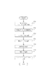
図5は、画像形成装置の制御ブロック図である。 FIG. 5 is a control block diagram of the image forming apparatus.
制御部501は、CPU502、ROM503、及びRAM504を有する。CPU502は、画像形成装置100全体を制御する制御回路である。ROM503には、画像形成装置100で実行する各種処理を制御するための制御プログラムが格納されている。
The
RAM504は、CPU502が動作するためのシステムワークメモリであり、また画像データを一時記憶するための画像メモリとしても機能する。ハードディスクドライブ(HDD)505には、システムソフトウェア、画像データ等のデータが格納されている。表示部506は、タッチパネルディスプレイで構成されており、ユーザからの操作入力の受け付け及び画像形成装置100に関する情報の表示を行う。
A
ROM503には、中間転写ベルト8の接触子202が当接する側におけるベルト1周分の端部の形状データであるエッジプロファイルデータPが、後述する中間転写ベルト8の特異点を基準として予め格納されている。制御部501において、CPU502は、ROM503にアクセスしてエッジプロファイルデータPを所定間隔で順次読み出す。
The
また、CPU502は、中間転写ベルト8の回転移動中に、エッジセンサ203からエッジデータEをエッジプロファイルデータPと同じ間隔で取り込む。そして、CPU502は、順次読み出したエッジプロファイルデータPと取り込んだエッジデータEから、中間転写ベルト8の蛇行量に相当する位置変化量を算出する。そして、CPU502は、算出した中間転写ベルト8の変位に応じて、蛇行が減少するようステアリングモータ209に対して駆動方向と駆動量からなるステアリング制御信号を出力して、ステアリングモータ209を駆動する。
Further, the
図6は、エッジデータと、エッジデータを微分した微分データとを示す図である。 FIG. 6 is a diagram illustrating edge data and differential data obtained by differentiating the edge data.
CPU502は、中間転写ベルト8の蛇行補正制御中、エッジセンサ203からの出力に基づいて中間転写ベルト8の幅方向の端部位置を示すエッジデータEを取得する(図6(a))。そして、CPU502は、エッジデータEの微分を行い、微分データDをRAM504に格納する。中間転写ベルト8の蛇行補正制御中、CPU502は、微分データDと予め設定された閾値Thとを比較し、この閾値以上の値を検出したら、微分データDにおける特異点Aと認識する(図6(b))。
During the meandering correction control of the
すなわち、中間転写ベルト8の幅方向の端部の単位時間あたりの位置変動が閾値Th以上となる位置を特異点Aとしている。この特異点Aは、中間転写ベルト8の繋ぎ目部分で発生する。
That is, the singular point A is a position where the position fluctuation per unit time of the end portion in the width direction of the
本実施形態では、ここで検出した特異点Aを中間転写ベルト8の基準点(ホームポジション)として、中間転写ベルト8の蛇行制御を行うものである。特異点Aの検出に用いられる閾値Thをどのように決定するかは、図7の説明のところで後述する。
In the present embodiment, meandering control of the
CPU502は、特異点Aを検出すると、RAM504に対してアドレスのリセット(アドレスを0000にする)をかける。RAM504には、特異点Aを基準(アドレス0000)とした、中間転写ベルト8の1周分のエッジプロファイルデータPが格納されている(図6(c))。CPU502は、特異点Aを基準として中間転写ベルト8の所定間隔ごとにアドレス値をカウントアップし、所定間隔でエッジプロファイルデータPをRAM504から読み出す。
When detecting the singular point A, the
CPU502は、エッジセンサ203からの出力に基づいて得られたエッジデータEと、RAM504から読み出したエッジプロファイルデータPとの差分から、中間転写ベルト8の幅方向の位置ずれ(蛇行量)を検出する。CPU502は、検出した蛇行量に基づいて、中間転写ベルト8の蛇行補正制御を行う。
The
図7は、エッジプロファイルデータPと、特異点Aを検出するための閾値Thの決定方法を示すフローチャートである。 FIG. 7 is a flowchart showing a method of determining the edge profile data P and the threshold value Th for detecting the singular point A.
このフローチャートを実行するためのプログラムは、ROM503に記憶されており、CPU502により読み出されることにより実行される。このフローチャートは、画像形成装置100の工場出荷時や中間転写ベルト8の交換時に、表示部506からの指示の入力に基づいて実行される。
A program for executing this flowchart is stored in the
まず、CPU502は、偏心カム208をニュートラル位置に固定する(S701)。ここで、ニュートラル位置とはステアリングローラを傾けない位置であり、中間転写ベルト8の幅方向の位置が安定する位置である。次に、CPU502は、ベルト駆動モータ210を駆動して中間転写ベルト8の駆動を開始する(S702)。そして、CPU502は、エッジセンサ203からの出力に基づいて中間転写ベルト8の1周分のエッジデータEを取得し(S703)、取得したエッジデータEを微分して中間転写ベルト8の1周分の微分データDを算出する(S704)。
First, the
次に、CPU502は、中間転写ベルト8の1周分の微分データDの最大値Dmaxを示す点を特異点Aとして検出し(S705)、このDmaxに所定の係数K(本実施形態は0.95)を乗じた値を閾値Thとする(S706)。そして、CPU502は、特異点Aを基準(アドレス0000)として中間転写ベルト8の回転方向の所定間隔ごとにアドレス値をカウントアップし、所定間隔でエッジセンサ203の出力値をエッジプロファイルデータPとしてRAM504に記憶する。このエッジプロファイルデータPは、中間転写ベルト8の1周分のエッジの位置変動を示すプロファイルデータである。
Next, the
図8は、中間転写ベルト8の蛇行補正制御を示すフローチャートである。
FIG. 8 is a flowchart showing meandering correction control of the
このフローチャートを実行するためのプログラムは、ROM503に記憶されており、CPU502により読み出されることにより実行される。
A program for executing this flowchart is stored in the
まず、CPU502は、ベルト駆動モータ210を駆動して中間転写ベルト8の駆動を開始する(S801)。次に、CPU502は、中間転写ベルト8の回転速度を一定に制御している状態で、エッジセンサ203からの出力に基づいてエッジデータEを取得し(S802)、取得したエッジデータEを微分して微分データDを算出する(S803)。
First, the
そして、CPU502は、微分データDと予め設定された閾値Thとを比較し、特異点Aを検出したかどうかを判断する(S804)。すなわち、前述の図6(b)に示されるように、CPU502は、微分データDが閾値Th以上の場合に特異点Aを検出したと判断する。
The
ステップS804において、特異点Aが検出されなかった場合は、CPU502は、特異点Aが検出されるまでステップS802〜S804の処理を繰り返す。特異点Aが検出された場合は、CPU502は、RAM504に対してアドレスXのリセット(アドレスを0000にする)をかける(S805)。そして、CPU502は、エッジセンサ203からの出力に基づいてエッジデータEを取得するとともに(S806)、アドレスXに対応するエッジプロファイルデータPをRAM504から取得する(S807)。
If the singular point A is not detected in step S804, the
ここで得られたエッジデータE及びエッジプロファイルデータPに基づいて、CPU502は、ステアリングデータSを算出する(S808)。具体的には、CPU502は、中間転写ベルト8の変位HをH=P−Eの計算式で求めた上で、ステアリングデータSをS=α・Hの計算式で求める。ここでαは所定の係数である。
Based on the edge data E and edge profile data P obtained here, the
そして、CPU502は、算出したステアリングデータSに基づき、ステアリングモータ209を駆動する(S809)。具体的には、CPU502は、算出したステアリングデータSに相当する偏心カムの回転位置θnと、現在のカム回転位置θoの差分θn−θoを算出する。そして、CPU502は、偏心カム208をθn−θo回転させるようステアリングモータ209へステアリング制御信号を出力する。これに応じて、ステアリングモータ209が制御されて、中間転写ベルト8の変位Hが0になる方向に揺動アーム206が動き、ステアリングローラ10が傾く。
Then, the
その後、CPU502は、画像形成動作の終了等で、蛇行補正制御を停止するかどうかを判断する(S810)。蛇行補正制御を停止しない場合は、CPU502は、アドレスXに1を加算する(S811)。そして、CPU502は、アドレスXがRAM504に記憶されているエッジプロファイルデータPの最大アドレスXmaxを超えたかどうかを判断する(S812)。
Thereafter, the
アドレスXがXmaxを超えた場合は、ステップS804で特異点Aを検出してから中間転写ベルト8の1周分の蛇行補正を完了したことになるので、ステップS802に戻りホームポジションとしての特異点Aの検出動作を再度行う。一方、アドレスXがXmax以下の場合は、ステップS806に戻って蛇行補正制御を継続する。
If the address X exceeds Xmax, meandering correction for one turn of the
ステップS810において、蛇行補正制御を停止する場合は、CPU502は本制御フローを終了する。
In step S810, if the meandering correction control is to be stopped, the
以上で説明したように、本実施形態では、中間転写ベルト8にベルトHP(ホームポジション)マークを設けずに、微分データDの特異点Aを検出した位置を中間転写ベルト8のホームポジションとして中間転写ベルト8の蛇行制御を行う。これによって、ベルトHPマークを検出するベルトHPセンサを設ける必要が無く、画像形成装置100の大型化及びコストアップを防止できる。
As described above, in this embodiment, the
なお、中間転写ベルト8が繋ぎ目の無いシームレスのベルトの場合は、特異点Aの検出が困難となる。この場合、中間転写ベルト8の特異点Aをより正確に検知するために、図9(a)に示されるように中間転写ベルト8の接触子202が当接する側の端部に突起8aを設けてもよい。また、図9(b)に示されるように中間転写ベルト8の接触子202が当接する側の端部に切り込み8bを設けてもよい。突起又は切り込みに接触子202が接触すると微分データDを大きく変動させることができるので、より正確にホームポジションの検出ができる。
When the
また、上記の説明では、ベルトとして中間転写ベルトを例に説明したが、これに限られない。例えば、ベルト式の定着器に用いられる定着ベルトや、記録紙を搬送するための記録紙搬送ベルト等、画像形成装置10内に設けられたベルトの蛇行補正制御及びホームポジション検知動作に、本発明を適用してもかまわない。
In the above description, the intermediate transfer belt has been described as an example of the belt, but is not limited thereto. For example, the present invention is applicable to the meandering correction control and home position detection operation of a belt provided in the
1 画像形成装置
8 中間転写ベルト
10 ステアリングローラ
11 ベルト駆動ローラ
202 接触子
203 エッジセンサ
209 ステアリングモータ
210 ベルト駆動モータ
403 変位センサ
501 制御部
502 CPU
503 ROM
504 RAM
DESCRIPTION OF
503 ROM
504 RAM
Claims (6)
前記ベルトの前記所定方向に直交する幅方向の端部の位置を検知するセンサと、
前記センサの出力に基づき、前記複数のローラのうちのいずれか1つのローラの軸を傾けることにより、前記幅方向の前記ベルトの位置を制御する制御手段と、を有し、
前記制御手段は、前記センサの出力に基づき、前記ベルトの前記幅方向の端部の単位時間あたりの位置変動が所定の閾値以上である位置を前記ベルトのホームポジションとして、前記幅方向の前記ベルトの位置を制御することを特徴とするベルト駆動装置。 A belt supported by a plurality of rollers and rotating in a predetermined direction;
A sensor for detecting the position of the end of the belt in the width direction perpendicular to the predetermined direction;
Control means for controlling the position of the belt in the width direction by inclining the axis of any one of the plurality of rollers based on the output of the sensor;
The control means, based on the output of the sensor, uses the belt in the width direction as a home position of the belt, where the position variation per unit time of the end of the belt in the width direction is a predetermined threshold or more. A belt driving device that controls the position of the belt.
前記制御手段は、前記センサの出力に基づき、前記ベルトの前記接触子に接触する側の端部の単位時間あたりの位置変動が所定の閾値以上である位置を前記ベルトのホームポジションとして、前記幅方向の前記ベルトの位置を制御することを特徴とする請求項1記載のベルト駆動装置。 A contact that contacts the end of the belt in the width direction perpendicular to the predetermined direction and is displaced according to the position of the belt in the width direction;
Based on the output of the sensor, the control means sets, as a position where the position variation per unit time of the end of the belt that contacts the contact is equal to or greater than a predetermined threshold, as the belt home position, the width 2. The belt driving device according to claim 1, wherein the belt position in the direction is controlled.
前記制御手段は、前記記憶手段に記憶された前記エッジプロファイルデータと、前記ベルトの回転移動中に前記センサの出力により得られるエッジデータとに基づき、前記幅方向の前記ベルトの位置を制御することを特徴とする請求項2記載のベルト駆動装置。 Storage means for storing edge profile data indicating the shape data of the end of the belt on which the contact comes into contact;
The control means controls the position of the belt in the width direction based on the edge profile data stored in the storage means and edge data obtained by the output of the sensor during the rotational movement of the belt. The belt driving device according to claim 2.
記録紙に画像を形成する画像形成手段と、を有し、
前記ベルトは、中間転写ベルト、定着ベルト、又は記録紙搬送ベルトであることを特徴とする画像形成装置。 A belt driving device according to any one of claims 1 to 5;
Image forming means for forming an image on a recording paper,
The image forming apparatus, wherein the belt is an intermediate transfer belt, a fixing belt, or a recording paper conveyance belt.
Priority Applications (1)
| Application Number | Priority Date | Filing Date | Title |
|---|---|---|---|
| JP2009282290A JP5404362B2 (en) | 2009-12-11 | 2009-12-11 | Belt drive device and image forming apparatus |
Applications Claiming Priority (1)
| Application Number | Priority Date | Filing Date | Title |
|---|---|---|---|
| JP2009282290A JP5404362B2 (en) | 2009-12-11 | 2009-12-11 | Belt drive device and image forming apparatus |
Publications (2)
| Publication Number | Publication Date |
|---|---|
| JP2011123382A JP2011123382A (en) | 2011-06-23 |
| JP5404362B2 true JP5404362B2 (en) | 2014-01-29 |
Family
ID=44287299
Family Applications (1)
| Application Number | Title | Priority Date | Filing Date |
|---|---|---|---|
| JP2009282290A Expired - Fee Related JP5404362B2 (en) | 2009-12-11 | 2009-12-11 | Belt drive device and image forming apparatus |
Country Status (1)
| Country | Link |
|---|---|
| JP (1) | JP5404362B2 (en) |
Families Citing this family (3)
| Publication number | Priority date | Publication date | Assignee | Title |
|---|---|---|---|---|
| JP5425847B2 (en) | 2011-09-07 | 2014-02-26 | シャープ株式会社 | Fixing apparatus and image forming apparatus |
| JP5542108B2 (en) * | 2011-11-04 | 2014-07-09 | 京セラドキュメントソリューションズ株式会社 | Image forming apparatus and index detection method for image forming apparatus |
| JP5331907B2 (en) * | 2012-02-08 | 2013-10-30 | 京セラドキュメントソリューションズ株式会社 | Image forming apparatus |
Family Cites Families (10)
| Publication number | Priority date | Publication date | Assignee | Title |
|---|---|---|---|---|
| JP3636273B2 (en) * | 1998-02-05 | 2005-04-06 | 富士ゼロックス株式会社 | Image forming belt device |
| JPH11295948A (en) * | 1998-04-15 | 1999-10-29 | Fuji Xerox Co Ltd | Belt driving device and image forming device provided with same |
| JP3633294B2 (en) * | 1998-07-22 | 2005-03-30 | 富士ゼロックス株式会社 | Belt drive device and image forming apparatus having the same |
| JP3903632B2 (en) * | 1999-03-16 | 2007-04-11 | 富士ゼロックス株式会社 | Belt conveying apparatus and image forming apparatus |
| JP2001005235A (en) * | 1999-06-17 | 2001-01-12 | Canon Inc | Image forming device |
| JP2004102037A (en) * | 2002-09-11 | 2004-04-02 | Canon Inc | Image forming apparatus |
| JP2004198674A (en) * | 2002-12-18 | 2004-07-15 | Seiko Epson Corp | Image forming apparatus |
| JP4965124B2 (en) * | 2005-12-28 | 2012-07-04 | 株式会社リコー | Belt running device and image forming apparatus |
| JP4254814B2 (en) * | 2006-06-19 | 2009-04-15 | コニカミノルタビジネステクノロジーズ株式会社 | Image forming apparatus and image forming method |
| JP2009282445A (en) * | 2008-05-26 | 2009-12-03 | Fuji Xerox Co Ltd | Rotating device of belt-like member and program |
-
2009
- 2009-12-11 JP JP2009282290A patent/JP5404362B2/en not_active Expired - Fee Related
Also Published As
| Publication number | Publication date |
|---|---|
| JP2011123382A (en) | 2011-06-23 |
Similar Documents
| Publication | Publication Date | Title |
|---|---|---|
| JP5825873B2 (en) | Image forming apparatus | |
| JP2011020842A (en) | Sheet length measuring device and image forming device | |
| JP6286822B2 (en) | Multifeed determination device, image forming apparatus, multifeed determination method, and multifeed determination method program | |
| JP5404362B2 (en) | Belt drive device and image forming apparatus | |
| JP2001083840A (en) | Belt meandering suppression device | |
| JP5858613B2 (en) | Belt drive device and image forming apparatus | |
| JP2009286609A (en) | Carrying control device and image forming device | |
| JP4693690B2 (en) | Image forming apparatus and image forming apparatus control method | |
| JP5264461B2 (en) | Belt drive device and image forming apparatus | |
| JP2012128292A (en) | Belt driving device and image forming apparatus | |
| JP4376196B2 (en) | Image forming apparatus | |
| JP2011248056A (en) | Image forming apparatus | |
| JP5183452B2 (en) | Belt drive device and image forming apparatus | |
| JP5409017B2 (en) | Image forming apparatus and method for controlling image forming apparatus | |
| JP5880061B2 (en) | Image forming apparatus | |
| JP5404305B2 (en) | Belt drive device and image forming apparatus | |
| US9323172B2 (en) | Image forming apparatus provided with image formation position correction function | |
| JP2012226244A (en) | Image forming device and control method thereof | |
| US20220390888A1 (en) | Image forming apparatus | |
| JP2008030883A (en) | Paper conveying device and paper posture correcting method | |
| JP2012254875A (en) | Recording material conveying device and image forming apparatus | |
| JP2008233286A (en) | Image forming apparatus | |
| JP5553736B2 (en) | Belt drive device and image forming apparatus | |
| JP6657840B2 (en) | Sheet conveying device, image forming device, sheet characteristic estimating method | |
| JP6395583B2 (en) | Image forming apparatus |
Legal Events
| Date | Code | Title | Description |
|---|---|---|---|
| A621 | Written request for application examination |
Free format text: JAPANESE INTERMEDIATE CODE: A621 Effective date: 20120910 |
|
| A977 | Report on retrieval |
Free format text: JAPANESE INTERMEDIATE CODE: A971007 Effective date: 20130919 |
|
| A01 | Written decision to grant a patent or to grant a registration (utility model) |
Free format text: JAPANESE INTERMEDIATE CODE: A01 Effective date: 20131001 |
|
| A61 | First payment of annual fees (during grant procedure) |
Free format text: JAPANESE INTERMEDIATE CODE: A61 Effective date: 20131029 |
|
| LAPS | Cancellation because of no payment of annual fees |