JP5402665B2 - Projector device - Google Patents
Projector device Download PDFInfo
- Publication number
- JP5402665B2 JP5402665B2 JP2010009303A JP2010009303A JP5402665B2 JP 5402665 B2 JP5402665 B2 JP 5402665B2 JP 2010009303 A JP2010009303 A JP 2010009303A JP 2010009303 A JP2010009303 A JP 2010009303A JP 5402665 B2 JP5402665 B2 JP 5402665B2
- Authority
- JP
- Japan
- Prior art keywords
- air
- filter
- air filter
- holder case
- holder
- Prior art date
- Legal status (The legal status is an assumption and is not a legal conclusion. Google has not performed a legal analysis and makes no representation as to the accuracy of the status listed.)
- Active
Links
Images


Classifications
-
- G—PHYSICS
- G03—PHOTOGRAPHY; CINEMATOGRAPHY; ANALOGOUS TECHNIQUES USING WAVES OTHER THAN OPTICAL WAVES; ELECTROGRAPHY; HOLOGRAPHY
- G03B—APPARATUS OR ARRANGEMENTS FOR TAKING PHOTOGRAPHS OR FOR PROJECTING OR VIEWING THEM; APPARATUS OR ARRANGEMENTS EMPLOYING ANALOGOUS TECHNIQUES USING WAVES OTHER THAN OPTICAL WAVES; ACCESSORIES THEREFOR
- G03B21/00—Projectors or projection-type viewers; Accessories therefor
- G03B21/14—Details
- G03B21/16—Cooling; Preventing overheating
-
- H—ELECTRICITY
- H04—ELECTRIC COMMUNICATION TECHNIQUE
- H04N—PICTORIAL COMMUNICATION, e.g. TELEVISION
- H04N9/00—Details of colour television systems
- H04N9/12—Picture reproducers
- H04N9/31—Projection devices for colour picture display, e.g. using electronic spatial light modulators [ESLM]
- H04N9/3141—Constructional details thereof
- H04N9/3144—Cooling systems
Description
本発明は、液晶パネルやブラウン管等で作られた小型の表示装置の画像を、光学的に拡大して被投射面(スクリーン)に投射することで大画面を表示するプロジェクタ装置に関し、特に、装置内部を空気により冷却するプロジェクタ装置に関する。 The present invention relates to a projector device that displays a large screen by optically enlarging and projecting an image of a small display device made of a liquid crystal panel, a cathode ray tube, or the like onto a projection surface (screen). The present invention relates to a projector apparatus that cools the inside with air.
従来のプロジェクタ装置の第1の例としては、例えば、特許文献1に記載されているようなものがある。特許文献1には、光源からの光により原画を形成する画像形成素子を照明し、その画像形成素子からの光を被投射面に投射する画像投射装置に関するものが記載されている。画像投射装置は、塵埃除去フィルタを備えた吸気口を有する筐体と、吸気口を通じて筐体内に空気を吸い込むファンと、吸気口から吸い込まれた空気を、画像形成素子を包含する空間に導くダクトと、このダクトと吸気口との間に設けられた風洞室とを有している。そして、風洞室とダクトとの接続部におけるダクトへの空気の流入方向に直交する方向での風洞室の断面積が、接続部の断面積よりも大きいことを特徴としている。
As a first example of a conventional projector device, for example, there is one described in
また、従来のプロジェクタ装置の第2の例としては、例えば、特許文献2に記載されているようなものもある。特許文献2には、外装ケースに形成された空気取入口に、ファンにより吸収された空気から塵埃等を除去するための第1のフィルタが設けられたプロジェクタに関するものが記載されている。このプロジェクタは、第1のフィルタよりも広面積の第2のフィルタを有するフィルタユニットを、第1のフィルタの外側から空気取入口を覆うように外装ケースに着脱自在としたことを特徴としている。
Further, as a second example of the conventional projector device, there is one as described in
しかしながら、従来のプロジェクタ装置では、吸気口のすぐ内側にエアフィルタを配置し、そのエアフィルタの内側に吸気ファンを配置する構成となっていた。そして、吸気口から吸気されるエアを、エアフィルタを介して吸気ファンで直接吸気し、装置内部にエアを送り込む構成となっていたため、エアフィルタの面積を吸気口の面積と同等の面積しか確保できなかった。その結果、装置筐体のスペースの制約上から吸気口の面積を拡大することができず、エアフィルタの面積を拡大するためには、装置筐体のサイズを拡大しなければならず、装置全体が大型化してしまうという問題があった。 However, the conventional projector apparatus has a configuration in which an air filter is disposed immediately inside the intake port and an intake fan is disposed inside the air filter. And since the air sucked from the air intake is directly sucked by the air intake fan through the air filter and sent to the inside of the device, the area of the air filter is only as large as the area of the air intake. could not. As a result, the area of the intake port cannot be increased due to space limitations of the device housing, and in order to increase the area of the air filter, the size of the device housing must be increased, and the entire device There has been a problem of increasing the size.
この点に関して、特許文献1に記載された第1の従来例の場合には、装置筐体の内部を空気により冷却するために、光学系冷却ファンとランプ冷却ファンと電源冷却ファンとが設けられている。光学系冷却ファンは、液晶パネルや偏光板等の光学素子を冷却するためのもので、外装キャビネットに設けた吸気口にダクトを介して接続されている。ランプ冷却ファンは、光源ランプを冷却するためのものであり、ダクトを介して吸気口と接続されている。また、電源冷却ファンは、PFC電源ユニットとバラスト電源ユニットを冷却するためのもので、同じくダクトを介して吸気口と接続されている。吸気口には、吸い込まれた空気から塵埃を除去する塵埃除去フィルタが設けられており、これにより塵埃の除去された空気が、ダクトを介して分配されて各冷却ファンに供給されるように構成されている。そのため、エアフィルタの面積を拡大するためには、装置筐体のサイズを拡大しなければならず、装置全体が大型化してしまうという同様の問題があった。
In this regard, in the case of the first conventional example described in
また、特許文献2に記載された第2の従来例の場合には、第1のフィルタよりも広い面積を有する第2のフィルタを、第1のフィルタの外側から空気取入口を覆うように配置する構成となっていた。そのため、第1の従来例の場合と同様に、エアフィルタの面積を拡大するためには、装置筐体のサイズを拡大しなければならず、装置全体が大型化してしまうという問題があった。
In the case of the second conventional example described in
解決しようとする問題点は、従来のプロジェクタ装置では、吸気口のすぐ内側にエアフィルタを配置し、その内側に吸気ファンを配置して、吸気口から吸気されるエアを、エアフィルタを介して吸気ファンで直接吸気して装置内部に送り込む構成となっていた。そのため、エアフィルタの面積を吸気口の面積と同等の面積しか確保することができず、エアフィルタの面積を拡大するためには装置筐体のサイズを拡大しなければならず、装置全体が大型化してしまうことである。 The problem to be solved is that in the conventional projector device, an air filter is arranged just inside the air intake port, an air intake fan is arranged inside the air intake port, and the air sucked from the air intake port is passed through the air filter. The air intake fan directly inhales air and sends it into the device. For this reason, the area of the air filter can be ensured only as much as the area of the intake port, and in order to increase the area of the air filter, the size of the device housing must be increased, and the entire device is large. It is to become.
本発明のプロジェクタ装置は、光源からの光により画像形成素子を照明して画像を被投射面に投射するプロジェクタ装置に関する。光源及び画像形成素子が収納された装置筐体と、その装置筐体に設けられると共に空気を取り入れる吸気口を有するエアフィルタ収納部と、複数のエアフィルタと冷却ファンと第1の空気路と第2の空気路を設ける。複数のエアフィルタは、吸気口の開口面積と同程度の広さを有すると共に、エアフィルタ収納部内に重なり合うように対向設置される。冷却ファンは、周囲の空気を吸引することにより吸気口から空気を流入させると共に、その空気を複数のエアフィルタに通過させた後光源や画像形成素子に吹き付けて放熱させる。第1の空気路は、吸気口から流入される空気の一部を複数のエアフィルタのうち、吸気口に近い側に位置する前側エアフィルタに導き、その前側エアフィルタを通過させて冷却ファンに導く。また、第2の空気路は、空気の残部を、吸気口から遠い側に位置する後側エアフィルタに導き、その後側エアフィルタを通過させて冷却ファンに導く。 The projector apparatus of the present invention relates to a projector apparatus that illuminates an image forming element with light from a light source and projects an image on a projection surface. An apparatus housing in which the light source and the image forming element are housed, an air filter housing portion provided in the apparatus housing and having an intake port for taking in air, a plurality of air filters, a cooling fan, a first air path, and a first air passage Two air passages are provided. The plurality of air filters have the same size as the opening area of the intake port and are opposed to each other so as to overlap in the air filter storage portion. The cooling fan draws in air from the intake port by sucking ambient air, passes the air through a plurality of air filters, and then blows it to a light source or an image forming element to dissipate heat. The first air path leads a part of the air flowing in from the air intake port to a front air filter located on the side close to the air intake port among the plurality of air filters, and passes the front air filter to the cooling fan. Lead. Further, the second air path guides the remaining air to the rear air filter located on the side far from the intake port, and passes the rear air filter to the cooling fan.
本発明のプロジェクタ装置によれば、装置内部を冷却する空気を吸気するための吸気口の数や面積を増やすことなく、エアフィルタの面積を増やすことができる。そのため、装置全体が大型化されることなく、装置全体の小型化を維持したまま、面積が増大されたエアフィルタによって塵埃が取り除かれた大量の空気を冷却ファンに供給することができ、光源等の放熱効率を高めることができる。 According to the projector device of the present invention, the area of the air filter can be increased without increasing the number and area of the air inlets for sucking the air that cools the inside of the device. Therefore, a large amount of air from which dust has been removed by an air filter with an increased area can be supplied to a cooling fan while maintaining the downsizing of the entire device without increasing the size of the entire device, such as a light source The heat radiation efficiency can be increased.
吸気口の開口面積と同程度の面積(広さ)を有する複数のエアフィルタを、その吸気口の内側に重なり合うように対向設置すると共に、吸気口から流入される空気を第1の空気路と第2の空気路に分岐させて複数のエアフィルタに通過させる。これにより、吸気口の数や面積を増やすことなく、エアフィルタの面積を増大させて広範囲で塵埃を取り除くことができ、塵埃を除去した大量の空気を冷却ファンから光源等に供給することができるプロジェクタ装置を、比較的簡単な構成によって実現した。 A plurality of air filters having an area (width) approximately the same as the opening area of the air intake port are disposed opposite to each other so as to overlap the inside of the air intake port, and the air flowing from the air intake port is defined as the first air path. The air is branched into a second air passage and passed through a plurality of air filters. Accordingly, the area of the air filter can be increased and dust can be removed over a wide range without increasing the number and area of the air inlets, and a large amount of air from which dust has been removed can be supplied from the cooling fan to the light source or the like. The projector device was realized with a relatively simple configuration.
図1及び図2は、本発明のプロジェクタ装置(画像投射装置)の実施の形態の一例を示すものである。このプロジェクタ装置1は、外装ケースを構成する装置筐体2を備えている。
1 and 2 show an example of an embodiment of a projector apparatus (image projection apparatus) according to the present invention. The
装置筐体2は、上下に重ね合わされる上部筐体3及び下部筐体4と、上部筐体3に設けたエアフィルタ収納部5の開口部である吸気口9に着脱可能に装着される格子状カバー6とによって構成されている。上部筐体3と下部筐体4は、上下に重ね合わせた状態で、図示しない固定ねじによって締付固定されており、両筐体間に形成された空間部内に投射レンズユニット7や図示しない光源ユニット、光学ユニット、電源ユニット等が収納されている。
The
上部筐体3の正面部3aには貫通穴8が設けられており、その貫通穴8を貫通する投射レンズユニット7の先端部が、正面部3aから前方へ突出されている。投射レンズユニット7は、図示しない光源ユニットの光源からの光(画像)を、図示しないスクリーン(被投射面)に拡大して投射する。光源ユニットは、例えば、高圧水銀放電ランプ、ハロゲンランプ等の光源ランプを備えている。光学ユニットは、例えば、光源ランプからの光束を平行光束に変換する偏光変換素子と、平行光束を赤、緑、青の各色光束R、G、Bに分解して変調する画像形成素子としての3枚の液晶パネルと、変調された色光束を合成するプリズム合成体等を備えている。電源ユニットは、光源ユニットや光学ユニット等に電力を供給し、光源ランプを点灯制御すると共に、液晶パネルを駆動制御し、その他の装置・機器にも電力を供給し動作させて制御する。
A through
上部筐体3の左側面部には、2個のエアフィルタユニット10を着脱可能に装着することができる広さ(領域)を有するエアフィルタ収納部5が設けられている。このエアフィルタ収納部5の吸気口9に、格子状カバー6が着脱可能に装着されている。格子状カバー6は、比較的大きなゴミがエアフィルタ収納部5内に入り込むのを防止するもので、横方向に延在された複数の横桟6aと、縦方向に延在された複数の縦桟6bとを有している。また、下部筐体4の左側面部には開口窓11が設けられている。
On the left side surface portion of the upper housing 3, there is provided an air filter storage portion 5 having a size (area) in which two
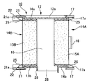
エアフィルタユニット10は、図3〜図5に示すような構成を有している。即ち、エアフィルタユニット10は、ホルダケース12と、2つのフィルタホルダ14A,14Bと、2つのエアフィルタ15A,15Bとによって構成されている。2つのフィルタホルダ14A,14Bは、ホルダケース12の両面に着脱可能に装着される。また、2つのエアフィルタ15A,15Bは、2つのフィルタホルダ14A,14Bに個別に装着される。
The
図3等に示すように、ホルダケース12は、上面部12aと下面部12bと左右の側面部12c、12dとで四方を囲うように形成された直方体をなす型枠状の部材からなっている。従って、ホルダケース12には、正面部から背面部まで貫通する直方体をなす空間部16が設けられている。ホルダケース12の正面側には、空間部16の周縁を囲うように外側に展開された四角形の枠状をなす前フランジ部12eが形成されている。また、ホルダケース12の背面側には、同じく空間部16の周縁を囲うように外側に展開された四角形の枠状をなす後フランジ部12fが形成されている。
As shown in FIG. 3 and the like, the
ホルダケース12の前フランジ部12eの上下方向に対向された二辺には、弾性を有する2つのロック片17,17が前方へ突出するようにそれぞれ設けられている。上下4つのロック片17,17は、上下及び左右の双方向に対称に配置されており、各ロック片17の先端には内側に突出する爪部17aが設けられている。更に、前フランジ部12eの左右方向(ホルダケース12の長手方向)に対向された二辺には、ホルダケース12を掴むための断面形状がL字状をなす取手18がそれぞれ設けられている。
Two
ホルダケース12の後フランジ部12fの上下方向に対向された二辺には、弾性を有する2つのロック片21,21が後方へ突出するようにそれぞれ設けられている。上下4つのロック片21,21は、上下及び左右の双方向に対称に配置されており、各ロック片21の先端には内側に突出する爪部21aが設けられている。更に、後フランジ部12fの四隅には、ロック片21よりも大きく後方へ突出する空気路用凸部22がそれぞれ設けられている。4つの空気路用凸部22,22は、エアフィルタ収納部5内に挿入されたエアフィルタユニット10の位置決め機能も兼ね備えている。
Two
即ち、装置筐体2の内部には、エアフィルタ収納部5の背面側を仕切る仕切り壁19が設けられている。この仕切り壁19に空気路用凸部22が突き当たるまでエアフィルタユニット10を差し込むことにより、エアフィルタユニット10がエアフィルタ収納部5内の所定位置に位置決めされる。これと同時に、4つの空気路用凸部22,22の内側に、エアフィルタユニット10の背面側に配置される後側エアフィルタ15Bの正面に空気を導く第2の空気路が形成される。
That is, a
2つのフィルタホルダ14A,14Bは同一のものであり、上面部14aと下面部14bと左右の側面部14c,14dとで四方を囲うように形成された直方体をなす型枠状の部材からなっている。従って、各フィルタホルダ14A,14Bには、正面部から背面部まで貫通する直方体をなす空間部が設けられている。2つのフィルタホルダ14A,14Bは、ホルダケース12の空間部16に対して、前方及び後方からそれぞれ着脱可能に装着される。
The two
また、各フィルタホルダ14A,14Bの正面側には、空間部を縁取りするように内側及び外側にそれぞれ展開された四角形の枠状をなすフランジ部14eが設けられている。フランジ部14eの上下方向に対向された二辺には、前方に突出する2つの爪受け部25,25がそれぞれ設けられている。上下4つの爪受け部25,25は、上下及び左右の双方向に対称であって、4つのロック片17,17と対応する位置に配設されている。組立時、4つの爪受け部25,25は4つのロック片17,17の内側にそれぞれ配置されることになり、先端の爪部17aが爪受け部25の先端にそれぞれ着脱可能に係合される
Further, on the front side of each of the
更に、各フィルタホルダ14A,14Bのフランジ部14eの上下方向(長手方向と直交する方向)に対向された二辺には、各フィルタホルダ14A,14Bを掴むための断面形状がL字状をなす取手26がそれぞれ設けられている。
Further, the cross-sectional shape for holding the
このような構成を有する各フィルタホルダ14A,14Bの空間部に、エアフィルタ15A,15Bが装着されている。エアフィルタ15A,15Bには、例えば、塵埃を吸着することができる不織布、ウレタンゴム等を用いることができる。しかしながら、エアフィルタの材料としては、これらに限定されるものではなく、静電フィルタ、その他各種のフィルタ材料を用いることができることは勿論である。
ホルダケース12の下面部12bには、冷却ファンへの空気の供給側となる連通口28が設けられている。連通口28は、下面部12bにおいて、一方の側面部12cから他方の側面部12dまで達する連続した幅広の長穴として形成されており、その周囲には下方に突出する囲い枠29が設けられている。
A
上部筐体3、下部筐体4、格子状カバー6、ホルダケース12及びフィルタホルダ14の材質としては、例えば、ABS(アクリロニトリル・ブタジエン・スチレン樹脂)が好適である。しかしながら、これらの材質として、ABSに限定されるものではなく、例えば、POM(ポリアセタール)、その他のエンジニアリングプラスチックを適用することができる。更に、ステンレス鋼板やスチール鋼板、アルミニウム合金その他の金属を用いることもできる。
For example, ABS (acrylonitrile butadiene styrene resin) is preferable as the material of the upper housing 3, the lower housing 4, the lattice cover 6, the
このような構成を有するエアフィルタユニット10が着脱可能に装着されるエアフィルタ収納部5に臨む部位には、光源ランプや光学ユニット等を冷却するための冷却ファン30が配設されている。冷却ファン30としては、多数の羽根をもつ羽根車を回転させることにより、その回転中心側から空気を吸引して羽根の外側から接線方向に空気を吐出させるシロッコファンを用いている。この冷却ファン(シロッコファン)30は、供給口31を上方へ向けた状態でエアフィルタ収納部5の下面部に配置されている。
A cooling
図6に示すように、冷却ファン30は、その供給口31を上方に向けた状態でベース部材32に固定されており、そのベース部材32が下部筐体4の凹部内に収納されて固定されている。エアフィルタ収納部5の所定位置にエアフィルタユニット10を装着すると、連通口28が冷却ファン30の供給口31に対向され、その供給口31から吸引される空気が、冷却ファン30の吐出口から吐出される。これにより、前後2箇所に対向するように配置された2つのエアフィルタ15A,15Bを経て塵埃の除去された多量の空気が、冷却ファン30により吸引され、光源ランプや光学ユニット等に吹き付けられる。
As shown in FIG. 6, the cooling
このエアフィルタユニット10を通過する空気のうち、吸気口9に近い側に配置された前側エアフィルタ15Aに向かう空気は、その正面から前側エアフィルタ15Aを通過してホルダケース12の空間部16内に入り込む。そして、ホルダケース12の下面部12bに設けた連通口28から冷却ファン30の供給口31に供給される。このときの空気の流路が、外気を冷却ファン30に導く第1の空気路41を構成している。
Of the air that passes through the
また、エアフィルタユニット10を通過する空気のうち、吸気口9から遠い側に配置された後側エアフィルタ15Bに向かう空気は、まず、ホルダケース12の上方に形成された上流路スペース5a内に入り込む。この流路スペース5a内に入り込んだ空気は、更に奥側に移動して、ホルダケース12の背面側に設けた4つの空気路用凸部22,22の間に形成された奥流路スペース5b内に入り込む。そして、吸気口9から遠い側に配置された後側エアフィルタ15Bの正面側に対向され、その後側エアフィルタ15Bを通過してホルダケース12の空間部16内に入り込む。その後、ホルダケース12の下面部12bに設けた連通口28から冷却ファン30の供給口31に供給される。このときの空気の流路が、外気を冷却ファン30に導く第2の空気路42を構成している。
Of the air that passes through the
このような構成を有するエアフィルタユニット10は、例えば、次のようにして組み立てることができる。予め、エアフィルタ15A,15Bを、2つのフィルタホルダ14A,14Bに装着しておく。次に、ホルダケース12の空間部16の一方の開口部に前側フィルタホルダ14Aを臨ませ、フランジ部14eの反対側から空間部16内に挿入する。このとき、前側フィルタホルダ14Aをある位置まで挿入すると、ホルダケース12の前フランジ部12eに設けた4つのロック片17の爪部17aの斜面部が、前側フィルタホルダ14Aのフランジ部14eに設けた爪受け部25の基部にそれぞれ当接される。
The
この場合、4つのロック片17は、それぞれが適当な強さの弾性を有するため、前側フィルタホルダ14Aを適当な力で押圧することにより、4つのロック片17は共に外側に弾性変形し、各爪部17aが爪受け部25をそれぞれ乗り越える。これにより、前側フィルタホルダ14Aが、ホルダケース12の一方の面(例えば、前面)に装着される。そして、爪受け部25を乗り越えた爪部17aがその爪受け部25の先端面に係合されるため、前側フィルタホルダ14Aがホルダケース12にロックされ、その前側フィルタホルダ14Aの抜け出しが防止される。
In this case, since each of the four
この際、前側フィルタホルダ14Aの外面には多数の突条部24が設けられているため、これら突条部24によってホルダケース12との間に生じているガタが吸収される。
At this time, since many protrusions 24 are provided on the outer surface of the
同様に、ホルダケース12の空間部16の他方の開口部に後側フィルタホルダ14Bを臨ませ、同じくフランジ部14eの反対側から空間部16内に挿入する。これにより、前側フィルタホルダ14Aの場合と同様にして、後側フィルタホルダ14Bを、ホルダケース12の他方の面(例えば、後面)に装着することができる。このとき、爪受け部25を乗り越えた爪部21aが、その爪受け部25の先端面に係合されるため、後側フィルタホルダ14Bはホルダケース12にロックされ、その後側フィルタホルダ14Bの抜け出しが防止される。
Similarly, the
この際、後側フィルタホルダ14Bの外面には多数の突条部24が設けられているため、これら突条部24によってホルダケース12との間に生じているガタが吸収される。
At this time, since many protrusions 24 are provided on the outer surface of the
ホルダケース12からフィルタホルダ14A,14Bを取り出す場合には、各フィルタホルダ14A,14Bにおいて、まず、4つのロック片17によるフィルタホルダ14A,14Bのロックを解除する。即ち、前側フィルタホルダ14Aにおいては、4つのロック片17の爪部17aによる爪受け部25の係合を解除する。また、後側フィルタホルダ14Bにおいては、4つのロック片21の爪部21aによる爪受け部25の係合を解除する。次に、各フィルタホルダ14A,14Bに設けた取手26を掴み、空間部16からフィルタホルダ14A(又は14B)を引き出す。これにより、各フィルタホルダ14A,14Bをホルダケース12から簡単に分離することができる。
When removing the
このようにフィルタホルダ14A,14Bが着脱されるエアフィルタユニット10の、プロジェクタ装置1のエアフィルタ収納部5に対する着脱作業は、例えば、次のように行うことができる。
The mounting and dismounting the
まず、図1に示すように、装置筐体2の上部筐体3から格子状カバー6を取り外し、2組のエアフィルタユニット10をエアフィルタ収納部5に臨ませる。そして、2組のエアフィルタユニット10を、後側フィルタホルダ14B側から挿入してエアフィルタ収納部5内に横並びに配置する。このとき、ホルダケース12の空気路用凸部22が仕切り壁19に当接するまでエアフィルタユニット10を差し込むことにより、エアフィルタ収納部5内の所定位置にエアフィルタユニット10を自動的に位置決めすることができる。これにより、ホルダケース12の連通口28が、下部筐体4に保持されている冷却ファン30の供給口31に合致される。その後、エアフィルタ収納部5の吸気口9に格子状カバー6を嵌め込むことにより、エアフィルタユニット10の組立作業が完了する。
First, as shown in FIG. 1, the grid-like cover 6 is removed from the upper housing 3 of the
一方、プロジェクタ装置1からエアフィルタユニット10を取り出す場合は、上述した組立作業と逆の作業によって簡単に行うことができる。まず、エアフィルタ収納部5の吸気口9から格子状カバー6を取り外す。次に、ホルダケース12に設けた2つの取手18,18を両手で掴み、エアフィルタユニット10を水平方向側方に引き出すようにする。これにより、エアフィルタユニット10をエアフィルタ収納部5から簡単に取り出すことができる。しかも、複数のエアフィルタを格納したホルダケース(カートリッジ)をエアフィルタ収納部5に対して出し入れするだけでエアフィルタの交換ができるため、エアフィルタの交換作業を極めて簡単且つ迅速に行うことができる。
On the other hand, when taking out the
上述したような構成を有する本願発明のプロジェクタ装置1によれば、冷却ファン30を駆動すると、冷却ファン30の吸引力によって供給口31に臨むエアフィルタユニット10側が負圧になる。この冷却ファン30の駆動により発生する負圧は、ホルダケース12の空間部16を経てエアフィルタ収納部5内の全体に作用し、更に、吸気口9を経て装置筐体2の外部にまで作用する。その結果、吸気口9の外に存在する空気E1の一部が、吸気口9からエアフィルタ収納部5内に入り込み、その空気E1の一部が第1の空気路41を通り、また、その空気の残部が第2の空気路42を通って、いずれも供給口31側に移動する。
According to the
即ち、図6に示すように、第1の空気路41を通る空気E1の一部は、吸気口9を入って直ぐに、ホルダケース12の吸気口9に近い側に保持されている前側エアフィルタ15Aを通過し、空間部16に到達する。一方、第2の空気路42を通る空気E1の残部は、吸気口9を入ってからホルダケース12の上方に移動し、ホルダケース12の上面とエアフィルタ収納部5の上面との間の流路スペース5aを通過してホルダケース12の背面側の流路スペース5bに移動する。そして、ホルダケース12の吸気口9から遠い側に保持されている後側エアフィルタ15Bを背面側から前面側に通過し、第2の空気路42を通る空気も空間部16に到達する。
That is, as shown in FIG. 6, a part of the air E <b> 1 passing through the
これらエアフィルタ15A,15Bを通過して塵埃の除去された空気E2が、空間部16から連通口28及び供給口31を経て冷却ファン30に供給され、装置筐体2の内部に送り込まれる。これにより、塵埃を除去した空気E2を大量に装置筐体2内に送り込み、光源ユニットや光学ユニット等を効率的に冷却することができる。
Air E <b> 2 from which dust has been removed through the
このように、本実施例によれば、2つのエアフィルタ15A,15Bを所定間隔あけて重なり合うように対向設置すると共に、これらのエアフィルタ15A,15Bに対して2つの空気路41,42を設けて個別に空気を通過させる構成とした。そのため、吸気口9の開口面積を増やすことなく、エアフィルタの面積を2倍に増やすことができ、空気から塵埃を除去する処理を2倍に増加することができる。これにより、エアフィルタ15A,15Bに目詰まりが生ずる期間を長くすることができ、エアフィルタの交換頻度を少なくして保守点検管理を容易にすることができる。更に、塵埃の溜まり方が少なくなるため、吸気量の低下を抑制することができ、吸気量の低下による冷却不足に起因する電子部品の温度上昇を抑制し、電子部品の劣化を抑制することができる。
As described above, according to the present embodiment, the two
このように、装置筐体2のスペース上の制約から吸気口9の数や面積に制限がある場合においても、その数や面積を増やすことなく、エアフィルタ面積を増やすことができる。その結果、空気の塵埃処理量を増加させて空気の吸気量を増やすことができ、装置筐体2内に設置されている装置、機器に対して、限られたスペースにおいて効率的に冷却することができる。また、複数のエアフィルタをカートリッジ(ホルダケース)に格納し、カートリッジを装置筐体2に対して着脱することにより、エアフィルタをワンタッチ操作で交換することができる。そのため、エアフィルタの交換作業を簡単なものとして、メンテナンスを容易にすることができる。
Thus, even when the number and area of the
更に、装置筐体2の内部に吸気エリア(流路スペース5a,5b)を設けることにより、吸気口の直ぐ内側の場所以外にもエアフィルタを配置することができるようになった。そのため、従来のプロジェクタ装置に較べて、限られたセットスペースにおいてエアフィルタの面積を増やすことができるようになった。なお、この実施例では、エアフィルタ収納部5に収納されたエアフィルタユニット10の上側に吸気エリア(流路スペース5a)を設けた例について説明したが、吸気エリア(流路スペース)は、エアフィルタユニット10の側方に設ける構成としてもよい。
Further, by providing the intake area (flow
以上説明したが、本発明は前記実施例に限定されるものではなく、本発明の要旨を逸脱しない範囲内で各種の変形実施が可能である。例えば、前記実施例では、前側エアフィルタ15Aと後側エアフィルタ15Bを同一のものを適用した例について説明したが、形状や大きさ、材質等が異なる別のものを適用できることは勿論である。更に、前記実施例では、2つのエアフィルタを用いた例について説明したが、3つ以上のエアフィルタを用いる構成とすることもできる。例えば、3つのエアフィルタを用いる場合には、所定間隔あけて重なり合うように配置すると共に、吸気エリアを2つに分岐して第2の空気路と第3の空気路を設け、3つの空気路を下流側で合流させるようにする。このように構成することによっても、空気から塵埃を除去する処理量を増加させて、空気の吸入量を増やすことができる。
As described above, the present invention is not limited to the above embodiments, and various modifications can be made without departing from the gist of the present invention. For example, in the above-described embodiment, the example in which the same
1…プロジェクタ装置(画像投射装置)、 2…装置筐体(外装ケース)、 3…上部筐体、 4…下部筐体、 5…エアフィルタ収納部、 5a,5b…流路スペース、 6…格子状カバー、 9…吸気口(開口部)、 10…エアフィルタユニット、 12…ホルダケース、 14,14A,14B…フィルタホルダ、 15,15A,15B…エアフィルタ、 16…空間部、 17,21…ロック片、 17a,21a…爪部、 18…取手、 19…仕切り壁、 22…空気路用凸部、 25…爪受け部、 26…取手、 28…連通口、 30…冷却ファン、 31…供給口、 41…第1の空気路、 42…第2の空気路、 E1,E2…空気
DESCRIPTION OF
Claims (6)
前記光源及び前記画像形成素子が収納された装置筐体と、
前記装置筐体に設けられると共に空気を取り入れる吸気口を有するエアフィルタ収納部と、
前記吸気口の開口面積と同程度の広さを有すると共に前記エアフィルタ収納部内に重なり合うように対向設置された複数のエアフィルタと、
周囲の空気を吸引することにより前記吸気口から空気を流入させると共に当該空気を前記複数のエアフィルタに通過させた後前記光源や前記画像形成素子に吹き付けて放熱させる冷却ファンと、
前記吸気口から流入される空気の一部を前記複数のエアフィルタのうち、前記吸気口に近い側に位置する前側エアフィルタに導き、当該前側エアフィルタを通過させて前記冷却ファンに導く第1の空気路と、
前記空気の残部を、前記吸気口から遠い側に位置する後側エアフィルタに導き、当該後側エアフィルタを通過させて前記冷却ファンに導く第2の空気路と、を設けた
プロジェクタ装置。 A projector device that illuminates an image forming element with light from a light source and projects an image on a projection surface,
An apparatus housing housing the light source and the image forming element;
An air filter housing portion provided in the apparatus housing and having an intake port for taking in air;
A plurality of air filters that have the same size as the opening area of the intake port and are opposed to be overlapped in the air filter storage unit;
A cooling fan that causes air to flow in from the air inlet by sucking ambient air and blows the air to the light source and the image forming element after passing the air through the plurality of air filters;
A part of the air flowing in from the air inlet is led to a front air filter located on a side near the air inlet among the plurality of air filters, and is passed through the front air filter and led to the cooling fan. The airway of
A projector device comprising: a second air path that guides the remaining portion of the air to a rear air filter located on a side far from the air inlet and guides the remaining air to the cooling fan through the rear air filter.
前記開口部に前記複数のエアフィルタを収納した前記ホルダケースを、前記エアフィルタ収納部に着脱可能に装着した
請求項1記載のプロジェクタ装置。 A holder case having an opening capable of accommodating the plurality of air filters is provided,
The projector apparatus according to claim 1, wherein the holder case storing the plurality of air filters in the opening is detachably attached to the air filter storage.
複数のフィルタホルダを前記開口部に装着することにより複数のエアフィルタを前記ホルダケースに着脱可能に保持した
請求項2記載のプロジェクタ装置。 Provide multiple filter holders to which the air filter is attached,
The projector apparatus according to claim 2, wherein a plurality of air filters are detachably held in the holder case by attaching a plurality of filter holders to the opening.
前記エアフィルタ収納部内に収納された前記ホルダケースの前記連通口を設けた面と対向する面の外側又は前記対向する面と直交する面の外側に前記第2の空気路を設けた
請求項2記載のプロジェクタ装置。 The holder case is provided with a communication port that communicates with the suction side of the cooling fan,
The second air path is provided on the outside of the surface facing the surface of the holder case housed in the air filter housing portion, or on the outside of the surface orthogonal to the facing surface. The projector apparatus as described.
請求項3記載のプロジェクタ装置。 The projector device according to claim 3, wherein the holder case is provided with an elastic lock piece for fixing the filter holder.
請求項2記載のプロジェクタ装置。 The holder case is provided with a handle for taking the holder case into and out of the air filter housing portion, and a positioning projection for positioning the holder case at a predetermined position in the air filter housing portion when inserted. The projector device according to claim 2.
Priority Applications (3)
| Application Number | Priority Date | Filing Date | Title |
|---|---|---|---|
| JP2010009303A JP5402665B2 (en) | 2010-01-19 | 2010-01-19 | Projector device |
| US12/930,604 US8485670B2 (en) | 2010-01-19 | 2011-01-11 | Projector apparatus |
| CN2011100053221A CN102129158A (en) | 2010-01-19 | 2011-01-12 | Projector apparatus |
Applications Claiming Priority (1)
| Application Number | Priority Date | Filing Date | Title |
|---|---|---|---|
| JP2010009303A JP5402665B2 (en) | 2010-01-19 | 2010-01-19 | Projector device |
Publications (3)
| Publication Number | Publication Date |
|---|---|
| JP2011150014A JP2011150014A (en) | 2011-08-04 |
| JP2011150014A5 JP2011150014A5 (en) | 2013-02-07 |
| JP5402665B2 true JP5402665B2 (en) | 2014-01-29 |
Family
ID=44267297
Family Applications (1)
| Application Number | Title | Priority Date | Filing Date |
|---|---|---|---|
| JP2010009303A Active JP5402665B2 (en) | 2010-01-19 | 2010-01-19 | Projector device |
Country Status (3)
| Country | Link |
|---|---|
| US (1) | US8485670B2 (en) |
| JP (1) | JP5402665B2 (en) |
| CN (1) | CN102129158A (en) |
Families Citing this family (10)
| Publication number | Priority date | Publication date | Assignee | Title |
|---|---|---|---|---|
| JP5643030B2 (en) * | 2010-08-30 | 2014-12-17 | 三洋電機株式会社 | Projection display |
| JP2013011689A (en) * | 2011-06-28 | 2013-01-17 | Sanyo Electric Co Ltd | Projection video display device |
| CN103379767B (en) * | 2012-04-20 | 2016-11-09 | 三洋科技中心(深圳)有限公司 | The fixed mechanism of dust-proof net cover and the projection arrangement containing this fixed mechanism |
| JP5641458B1 (en) | 2013-08-13 | 2014-12-17 | 株式会社リコー | Image projection device |
| CN206115124U (en) * | 2016-09-05 | 2017-04-19 | 深圳市光峰光电技术有限公司 | Dustproof filtration and have its projection arrangement |
| JPWO2018079024A1 (en) | 2016-10-31 | 2019-09-12 | ソニー株式会社 | Image projection unit and filter box |
| JP7047376B2 (en) * | 2017-12-27 | 2022-04-05 | セイコーエプソン株式会社 | projector |
| JP7127405B2 (en) * | 2018-07-25 | 2022-08-30 | セイコーエプソン株式会社 | Electronic equipment, projection equipment |
| CN110955100B (en) * | 2019-12-13 | 2022-01-28 | 深圳市杰奇科技创新有限公司 | Projector heat dissipation and dust prevention device beneficial to centrifugal force principle |
| CN112255870A (en) * | 2020-09-02 | 2021-01-22 | 芜湖宏嘉科技有限公司 | Projecting apparatus with adjustable intelligence teaching is used |
Family Cites Families (13)
| Publication number | Priority date | Publication date | Assignee | Title |
|---|---|---|---|---|
| JP2001021176A (en) * | 1999-07-08 | 2001-01-26 | Denso Corp | Air conditioning device |
| JP2001343707A (en) * | 2000-05-30 | 2001-12-14 | Hiroyuki Terasaki | Dustproof device of optical electronic apparatus |
| US6533835B2 (en) * | 2001-04-27 | 2003-03-18 | Mark Wilson | Supplemental filter for an electronic component |
| JP2004109781A (en) * | 2002-09-20 | 2004-04-08 | Seiko Epson Corp | Projector |
| JP4096702B2 (en) | 2002-11-07 | 2008-06-04 | セイコーエプソン株式会社 | projector |
| KR20050090835A (en) * | 2004-03-10 | 2005-09-14 | 엘지전자 주식회사 | Projection optical system |
| JP2007103748A (en) * | 2005-10-06 | 2007-04-19 | Seiko Epson Corp | Heat exchanger, liquid-cooling system, light source equipment, projector, electronic device unit, and electronic equipment |
| WO2008090825A1 (en) * | 2007-01-26 | 2008-07-31 | Panasonic Corporation | Powder dust capture device and projection type image display device |
| JP2009003317A (en) * | 2007-06-25 | 2009-01-08 | Seiko Epson Corp | Projector |
| JP4956837B2 (en) * | 2007-10-05 | 2012-06-20 | Necディスプレイソリューションズ株式会社 | Electronic device cooling apparatus and liquid crystal projector apparatus including the same |
| JP5127474B2 (en) * | 2008-01-24 | 2013-01-23 | キヤノン株式会社 | Image projection device |
| JP5247268B2 (en) * | 2008-07-08 | 2013-07-24 | 三洋電機株式会社 | Projection-type image display device |
| TWI406082B (en) * | 2009-06-04 | 2013-08-21 | Delta Electronics Inc | Projection apparatus and cooling device thereof |
-
2010
- 2010-01-19 JP JP2010009303A patent/JP5402665B2/en active Active
-
2011
- 2011-01-11 US US12/930,604 patent/US8485670B2/en active Active
- 2011-01-12 CN CN2011100053221A patent/CN102129158A/en active Pending
Also Published As
| Publication number | Publication date |
|---|---|
| CN102129158A (en) | 2011-07-20 |
| JP2011150014A (en) | 2011-08-04 |
| US8485670B2 (en) | 2013-07-16 |
| US20110176117A1 (en) | 2011-07-21 |
Similar Documents
| Publication | Publication Date | Title |
|---|---|---|
| JP5402665B2 (en) | Projector device | |
| JP4609490B2 (en) | Image display device and rear projector | |
| JP2011150014A5 (en) | ||
| JP2012048180A (en) | Projection type display device | |
| US7946713B2 (en) | Display apparatus | |
| US9599880B2 (en) | Projection display apparatus | |
| JP2011170270A (en) | Projector device | |
| JP6777092B2 (en) | Projection type display device | |
| JP2012008179A (en) | Projector | |
| JP5589441B2 (en) | Filter device and projector device | |
| JP5559004B2 (en) | Image projection device | |
| JP2007212568A5 (en) | ||
| JP5589442B2 (en) | Projector device | |
| US20110279786A1 (en) | Projection display device | |
| JP2011141445A (en) | Projector device | |
| JP2008170854A (en) | Projector | |
| JP5195526B2 (en) | projector | |
| JP3772908B2 (en) | Projection display | |
| JP2012086139A (en) | Dustproof filter device and projection type image display device | |
| US20110279785A1 (en) | Projection display device | |
| JP2012242538A (en) | Projector | |
| JP4093268B2 (en) | Optical unit device for projection display device | |
| JP2011150141A (en) | Image projection device | |
| JP2005326891A (en) | Projection type display device | |
| JP2004170745A (en) | Dust-proof unit for projector and the projector |
Legal Events
| Date | Code | Title | Description |
|---|---|---|---|
| A521 | Written amendment |
Free format text: JAPANESE INTERMEDIATE CODE: A523 Effective date: 20121213 |
|
| A621 | Written request for application examination |
Free format text: JAPANESE INTERMEDIATE CODE: A621 Effective date: 20121213 |
|
| A977 | Report on retrieval |
Free format text: JAPANESE INTERMEDIATE CODE: A971007 Effective date: 20130926 |
|
| TRDD | Decision of grant or rejection written | ||
| A01 | Written decision to grant a patent or to grant a registration (utility model) |
Free format text: JAPANESE INTERMEDIATE CODE: A01 Effective date: 20131001 |
|
| A61 | First payment of annual fees (during grant procedure) |
Free format text: JAPANESE INTERMEDIATE CODE: A61 Effective date: 20131014 |
|
| R151 | Written notification of patent or utility model registration |
Ref document number: 5402665 Country of ref document: JP Free format text: JAPANESE INTERMEDIATE CODE: R151 |
|
| A977 | Report on retrieval |
Free format text: JAPANESE INTERMEDIATE CODE: A971007 Effective date: 20131118 |
|
| R250 | Receipt of annual fees |
Free format text: JAPANESE INTERMEDIATE CODE: R250 |
|
| R250 | Receipt of annual fees |
Free format text: JAPANESE INTERMEDIATE CODE: R250 |
|
| R250 | Receipt of annual fees |
Free format text: JAPANESE INTERMEDIATE CODE: R250 |
|
| R250 | Receipt of annual fees |
Free format text: JAPANESE INTERMEDIATE CODE: R250 |
|
| R250 | Receipt of annual fees |
Free format text: JAPANESE INTERMEDIATE CODE: R250 |