JP5402111B2 - Blower - Google Patents
Blower Download PDFInfo
- Publication number
- JP5402111B2 JP5402111B2 JP2009057720A JP2009057720A JP5402111B2 JP 5402111 B2 JP5402111 B2 JP 5402111B2 JP 2009057720 A JP2009057720 A JP 2009057720A JP 2009057720 A JP2009057720 A JP 2009057720A JP 5402111 B2 JP5402111 B2 JP 5402111B2
- Authority
- JP
- Japan
- Prior art keywords
- air
- exhaust
- main body
- blower
- air supply
- Prior art date
- Legal status (The legal status is an assumption and is not a legal conclusion. Google has not performed a legal analysis and makes no representation as to the accuracy of the status listed.)
- Expired - Fee Related
Links
Images


Description
本発明は、建物内の室内換気を目的とし、室内の汚染空気と屋外の新鮮空気をファンモータによる送風によって、速やかに換気を行う送風装置に関するものである。 The present invention relates to an air blower that quickly ventilates indoor contaminated air and fresh outdoor air by blowing air with a fan motor for the purpose of indoor ventilation in a building.
従来、建物内の室内換気を行う場合、室内と屋外の間にファンモータを実装した送風装置を設置し、この送風装置の室内側と屋外側各々にダクトを接続する方法が知られている。 Conventionally, when indoor ventilation is performed in a building, a method is known in which a blower mounted with a fan motor is installed between the room and the outside, and a duct is connected to each of the indoor side and the outdoor side of the blower.
送風装置の従来例として図8を参照しながら説明する。 A conventional example of the blower will be described with reference to FIG.
図8に示すように、本体101は、給気側風路102に給気送風機103と排気側風路104に排気送風機105を有し、本体101と室内106および本体101と屋外107を連通するダクト108が接続する接続口109を本体101の側面101Aに有している。給気側風路102と排気側風路104は、風路仕切112によって分けられている。本体101の四隅には、本体101を天井面110に固定する取付金具111が設けられている。この取付金具111と風路仕切112は直交し、給気側風路102の接続口109と給気送風機103および排気側風路104と排気送風機105が直線的に配し、本体101のメンテナンスは接続口109が配されていない側面101Aから実施する構成となっている(例えば、特許文献1参照)。
As shown in FIG. 8, the
この構成において、メンテナンスを実施する場合、給気送風機103と排気送風機105を側面101Aの本体点検口113から取り出すが、天井裏空間が狭い場合は作業が行い難く、また、天井材に取り付ける機器点検口114を本体101の投影下部ではなく本体101の横下に設けるため、本体101の設置位置と機器点検口114の設置位置に制限が必要である。
In this configuration, when performing maintenance, the
このような従来の送風装置では、空間の狭い天井裏に設置する場合、もしくは天井材に取り付ける機器点検口が送風装置の横下に設置できない場合、送風装置のメンテナンス作業が困難であるという課題がある。 In such a conventional blower, when installed in a ceiling behind a narrow space, or when an equipment inspection port attached to a ceiling material cannot be installed beside the blower, there is a problem that maintenance work of the blower is difficult. is there.
本発明は、このような従来の課題を解決するものであり、空間の狭い天井裏に設置する送風装置のメンテナンス作業を容易にし、省スペースで設置位置に制限のない送風装置を提供することを目的とする。 The present invention solves such a conventional problem, and facilitates maintenance work of a blower installed in a ceiling under a narrow space, and provides a blower that is space-saving and has no restriction on the installation position. Objective.
本発明の送風装置は、上記目的を達成するために、箱状の本体と、前記本体の側面には室内空気を吸い込む室内吸込口と室内に空気を吹き出す室内吹出口と屋外空気を吸い込む屋外吸込口と室外に空気を吹き出す屋外吹出口と、排気送風機を有する排気風路と給気送風機を有する給気風路とを有した送風装置において、前記排気風路と前記給気風路は前記本体内部で隔壁板によって上下2段に区切られ、この隔壁板には、前記排気送風機と前記給気送風機を駆動する電動機をその回転軸が隔壁板に鉛直になるように設け、前記電動機の回転軸延長上の前記本体の下面には、前記本体の投影面積より小さい面積の本体点検口を設け、前記隔壁板を水平方向にスライドができ、かつ前記隔壁板の一辺を中心軸として回転できるものである。 In order to achieve the above object, the air blower of the present invention has a box-shaped main body, an indoor suction port for sucking indoor air on the side surface of the main body, an indoor outlet for blowing air into the room, and an outdoor suction for sucking outdoor air. An air blower having an outdoor air outlet for blowing air to the mouth and the outside, an exhaust air passage having an exhaust air blower, and an air supply air passage having an air supply blower, wherein the exhaust air passage and the air supply air passage are inside the main body. The partition plate is divided into upper and lower stages, and the partition plate is provided with an electric motor for driving the exhaust blower and the air supply blower so that the rotation axis thereof is perpendicular to the partition plate. A main body inspection port having an area smaller than the projected area of the main body is provided on the lower surface of the main body , the partition plate can be slid in the horizontal direction, and can be rotated about one side of the partition plate as a central axis .
また、他の手段は、本体の側面外部に、前記電動機を駆動する駆動回路を内蔵した電装箱を設け、この電装箱は、前記本体の本体点検口を介して前記本体の内部から脱着可能なものである。 In addition, another means is provided outside the side surface of the main body with an electric box containing a drive circuit for driving the electric motor, and the electric box can be detached from the inside of the main body through the main body inspection port of the main body. Is.
また、他の手段は、排気送風機は排気ファンと排気ケーシングで構成され、給気送風機は給気ファンと給気ケーシングで構成され、排気ファンと給気ファンは電動機のシャフトに固定され、排気ケーシングと給気ケーシングが隔壁板に固定されているものである。 The other means is that the exhaust blower is composed of an exhaust fan and an exhaust casing, the air supply blower is composed of an air supply fan and an air supply casing, and the exhaust fan and the air supply fan are fixed to the shaft of the electric motor, The air supply casing is fixed to the partition plate.
また、他の手段は、室内空気を吸い込む室内吸込口と排気風路の間に排気チャンバー室を有し、前記排気チャンバーの内部に排気フィルターを有し、且つ本体点検口から前記排気フィルターを取出可能としたものである。 Further, the other means has an exhaust chamber between the indoor intake port for sucking indoor air and the exhaust air passage, has an exhaust filter inside the exhaust chamber, and takes out the exhaust filter from the main body inspection port. It is possible.
また、他の手段は、室外空気を吸い込む室外吸込口と給気風路の間に給気チャンバー室を有し、前記給気チャンバーの内部に給気フィルターを有し、且つ本体点検口から前記給気フィルターを取出可能としたものである。 Further, the other means has an air supply chamber chamber between the outdoor air inlet for sucking outdoor air and the air supply air passage, an air supply filter inside the air supply chamber, and the supply port from the main body inspection port. The air filter can be taken out.
また、他の手段は、吊り金具が本体の内部を横断し、前記吊り金具に電動機を配した隔壁板が固定されているものである。 Another means is that a suspension metal fitting crosses the inside of the main body, and a partition plate in which an electric motor is arranged on the suspension metal fitting is fixed.
また、他の手段は、前記電装箱と電動機を繋ぐ電気配線が、前記本体内部の給気風路の上側に配された排気風路内に有したものである。 Another means is that the electric wiring connecting the electric box and the electric motor is provided in an exhaust air passage disposed on the upper side of the air supply air passage inside the main body.
また、他の手段は、電動機が排気送風機を駆動する排気電動機と給気送風機を駆動する給気電動機で構成されたものである。 The other means is constituted by an exhaust motor that drives the exhaust blower and an air supply motor that drives the supply blower.
本発明によれば、箱状の本体と、前記本体の側面には室内空気を吸い込む室内吸込口と
室内に空気を吹き出す室内吹出口と屋外空気を吸い込む屋外吸込口と室外に空気を吹き出す屋外吹出口と、排気送風機を有する排気風路と給気送風機を有する給気風路とを有した送風装置において、前記排気風路と前記給気風路は前記本体内部で隔壁板によって上下2段に区切られ、この隔壁板には、前記排気送風機と前記給気送風機を駆動する電動機をその回転軸が隔壁板に鉛直になるように設け、前記電動機の回転軸延長上の前記本体の下面には、前記本体の投影面積より小さい面積の本体点検口を設け、前記隔壁板を水平方向にスライドができ、かつ前記隔壁板の一辺を中心軸として回転できることにより、省スペースでメンテナンス作業が容易にできるという効果のある送風装置を提供することができる。
According to the present invention, a box-shaped main body, an indoor suction port for sucking indoor air on the side surface of the main body, an indoor air outlet for blowing air into the room, an outdoor suction port for sucking outdoor air, and an outdoor blower for blowing air outside the room. In a blower having an outlet, an exhaust air passage having an exhaust air blower, and an air supply air passage having an air supply blower, the exhaust air passage and the air supply air passage are divided into two upper and lower stages by a partition plate inside the main body. The partition plate is provided with an electric motor for driving the exhaust blower and the air supply blower so that the rotation shaft is perpendicular to the partition plate, and the lower surface of the main body on the extension of the rotation shaft of the motor the body access port area smaller than the projected area of the body is provided, the partition plate can slide in a horizontal direction, and by being able to rotate one side of the partition plate as a center axis, easily maintenance work in a small space It is possible to provide a blowing device which is effective that kill.
また、省スペースでメンテナンス作業を容易にでき、大きい直径の送風機を用いることができるので高静圧化を実現できる。 Further, maintenance work can be facilitated in a small space, and a high-diameter blower can be used, so that a high static pressure can be realized.
また、本体の側面外部に、前記電動機を駆動する駆動回路を内蔵した電装箱を設け、この電装箱は、前記本体の本体点検口を介して前記本体の内部から脱着可能なことにより、省スペースでメンテナンス作業が容易にできるという効果のある送風装置を提供することができる。 In addition, an electrical box containing a drive circuit for driving the electric motor is provided outside the side surface of the main body, and the electrical box can be detached from the inside of the main body via the main body inspection port of the main body, thereby saving space. Thus, it is possible to provide an air blowing device that has an effect of facilitating maintenance work.
また、排気送風機は排気ファンと排気ケーシングで構成され、給気送風機は給気ファンと給気ケーシングで構成され、排気ファンと給気ファンは電動機のシャフトに固定され、排気ケーシングと給気ケーシングが隔壁板に固定されていることにより、省スペースでメンテナンス作業を容易にできるという効果のある送風装置を提供することができる。 The exhaust fan is composed of an exhaust fan and an exhaust casing, the air supply fan is composed of an air supply fan and an air supply casing, the exhaust fan and the air supply fan are fixed to the shaft of the electric motor, and the exhaust casing and the air supply casing are By being fixed to the partition plate, it is possible to provide an air blowing device that has an effect of facilitating maintenance work while saving space.
また、室内空気を吸い込む室内吸込口と排気風路の間に排気チャンバー室を有し、前記排気チャンバーの内部に排気フィルターを有し、且つ本体点検口から前記排気フィルターを取出可能としたことにより、省スペースでメンテナンス作業が容易にできるという効果のある送風装置を提供することができる。 In addition, by having an exhaust chamber chamber between the indoor intake port for sucking indoor air and the exhaust air passage, having an exhaust filter inside the exhaust chamber, and enabling the exhaust filter to be taken out from the main body inspection port Thus, it is possible to provide an air blower having an effect that space-saving and easy maintenance work can be performed.
また、室外空気を吸い込む室外吸込口と給気風路の間に給気チャンバー室を有し、前記給気チャンバーの内部に給気フィルターを有し、且つ本体点検口から前記給気フィルターを取出可能としたことにより、省スペースでメンテナンス作業が容易にできるという効果のある送風装置を提供することができる。 In addition, it has an air supply chamber between the outdoor air intake port for sucking outdoor air and the air supply air passage, has an air supply filter inside the air supply chamber, and can take out the air supply filter from the main body inspection port As a result, it is possible to provide an air blower having an effect that space-saving and easy maintenance work can be performed.
また、吊り金具が本体の内部を横断し、前記吊り金具に電動機を配した隔壁板が固定されていることにより、本体を確実に吊ることができるという効果のある送風装置を提供することができる。 In addition, the suspension bracket traverses the inside of the main body, and the partition plate in which the electric motor is disposed on the suspension bracket is fixed, so that it is possible to provide an air blower having an effect that the main body can be reliably suspended. .
また、前記電装箱と電動機を繋ぐ電気配線が、前記本体内部の給気風路の上側に配された排気風路内に有したことにより、電気配線を本体内部結露から防ぐことができるという効果のある送風装置を提供することができる。 Further, since the electrical wiring connecting the electrical box and the electric motor is provided in the exhaust air passage disposed on the upper side of the air supply air passage inside the main body, the electric wiring can be prevented from dew condensation inside the main body. A certain blower can be provided.
また、電動機が排気送風機を駆動する排気電動機と給気送風機を駆動する給気電動機で構成されたことにより、排気風量および給気風量を各々調整できるという効果のある送風装置を提供することができる。 Further, since the electric motor is composed of the exhaust motor that drives the exhaust air blower and the air supply motor that drives the air supply air blower, it is possible to provide an air blowing device that has an effect that the exhaust air volume and the air supply air volume can be adjusted. .
本発明の請求項1記載の送風装置は、箱状の本体と、前記本体の側面には室内空気を吸い込む室内吸込口と室内に空気を吹き出す室内吹出口と屋外空気を吸い込む屋外吸込口と室外に空気を吹き出す屋外吹出口と、排気送風機を有する排気風路と給気送風機を有する給気風路とを有した送風装置において、前記排気風路と前記給気風路は前記本体内部で隔壁板によって上下2段に区切られ、この隔壁板には、前記排気送風機と前記給気送風機を駆動する電動機をその回転軸が隔壁板に鉛直になるように設け、前記電動機の回転軸延長上の前記本体の下面には、前記本体の投影面積より小さい面積の本体点検口を設け、前記隔壁板を水平方向にスライドができ、かつ前記隔壁板の一辺を中心軸として回転できることとしたものであり、本体の下面から排気送風機と給気送風機および各々を駆動する電動機のメンテナンスをするという作用を有する。
The air blower according to
また、隔壁板に落下防止機能をつけつつ、給気送風機もしくは排気送風機の平面を投影した2辺のうち1辺が本体点検口より大きい給気送風機もしくは排気送風機を本体内に設置できるという作用を有する。 In addition, the air supply blower or the exhaust blower can be installed in the main body with one side larger than the main body inspection port out of the two sides projected from the plane of the air supply blower or the exhaust blower while adding the fall prevention function to the partition plate. Have.
また、本体の側面外部に、前記電動機を駆動する駆動回路を内蔵した電装箱を設け、この電装箱は、前記本体の本体点検口を介して前記本体の内部から脱着可能なこととしたものであり、本体の下面から電装箱のメンテナンスをするという作用を有する。 In addition, an electrical box having a built-in drive circuit for driving the electric motor is provided outside the side surface of the main body, and the electrical box can be detached from the inside of the main body through the main body inspection port of the main body. Yes, it has the effect of maintaining the electrical box from the lower surface of the main body.
また、排気送風機は排気ファンと排気ケーシングで構成され、給気送風機は給気ファンと給気ケーシングで構成され、排気ファンと給気ファンは電動機のシャフトに固定され、排気ケーシングと給気ケーシングが隔壁板に固定されていることとしたものであり、本体の下面から排気送風機と給気送風機および各々を駆動する電動機のメンテナンスをするという作用を有する。 The exhaust fan is composed of an exhaust fan and an exhaust casing, the air supply fan is composed of an air supply fan and an air supply casing, the exhaust fan and the air supply fan are fixed to the shaft of the electric motor, and the exhaust casing and the air supply casing are It is supposed to be fixed to the partition plate, and has an effect of maintaining the exhaust blower, the supply blower, and the electric motor that drives each from the lower surface of the main body.
また、室内空気を吸い込む室内吸込口と排気風路の間に排気チャンバー室を有し、前記排気チャンバーの内部に排気フィルターを有し、且つ本体点検口から前記排気フィルターを取出可能としたこととしたものであり、本体の下面から排気フィルターのメンテナンスをするという作用を有する。 Also, an exhaust chamber chamber is provided between the indoor intake port for sucking indoor air and the exhaust air passage, an exhaust filter is provided inside the exhaust chamber, and the exhaust filter can be taken out from the main body inspection port. This has the effect of maintaining the exhaust filter from the lower surface of the main body.
また、室外空気を吸い込む室外吸込口と給気風路の間に給気チャンバー室を有し、前記給気チャンバーの内部に給気フィルターを有し、且つ本体点検口から前記給気フィルターを取出可能としたこととしたものであり、本体の下面から給気フィルターのメンテナンスをするという作用を有する。 In addition, it has an air supply chamber between the outdoor air intake port for sucking outdoor air and the air supply air passage, has an air supply filter inside the air supply chamber, and can take out the air supply filter from the main body inspection port This has the effect of maintaining the air supply filter from the lower surface of the main body.
また、吊り金具が本体の内部を横断し、前記吊り金具に電動機を配した隔壁板が固定されていることとしたものであり、重量物を吊り金具に支持させるという作用を有する。 In addition, the suspension fitting crosses the inside of the main body, and the partition plate in which the electric motor is arranged on the suspension fitting is fixed, and has an effect of supporting the heavy load on the suspension fitting.
また、前記電装箱と電動機を繋ぐ電気配線が、前記本体内部の給気風路の上側に配された排気風路内に有したこととしたものであり、結露の発生の恐れがある給気風路の上側に電気配線を配した排気風路を配するという作用を有する。 In addition, the electrical wiring that connects the electrical box and the electric motor is provided in the exhaust air passage disposed on the upper side of the air supply air passage inside the main body, and there is a risk that condensation may occur. It has the effect | action of arrange | positioning the exhaust air path which has arrange | positioned the electrical wiring on the upper side.
また、電動機が排気送風機を駆動する排気電動機と給気送風機を駆動する給気電動機で構成されたこととしたものであり、風路の圧力損失に対応した電動機出力を排気送風機お
よび給気送風機の各々に入力するという作用を有する。
In addition, the electric motor is composed of an exhaust motor that drives the exhaust blower and an air supply motor that drives the supply air blower, and the motor output corresponding to the pressure loss of the air passage is the output of the exhaust blower and the supply air blower. It has the effect of inputting to each.
以下、本発明の実施の形態について、図面を参照しながら説明する。 Hereinafter, embodiments of the present invention will be described with reference to the drawings.
(実施の形態1)
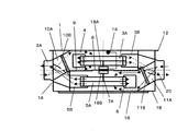
図1〜図6に示すように、板金の折り曲げ等で構成された箱状の送風装置の本体1と、この本体1の側面1Aには室内空気を吸い込む室内吸込口2Aと室内に空気を吹き出す室内吹出口2Bと屋外空気を吸い込む屋外吸込口2Cと室外に空気を吹き出す屋外吹出口2Dが設けられている。これらは、接続口109に接続されたダクト108によって、屋外および室内と接続されている。本体1の内部には、排気風路4と、給気風路6の2つの風路が設けられ、それぞれの風路に排気送風機3Cと、給気送風機5Cが設けられている。排気送風機3Cは、排気ファン3Aと排気ケーシング3Bで構成されている。給気送風機5Cは、給気ファン5Aと給気ケーシング5Bで構成されている。排気風路4は、室内吸込口2Aと屋外吹出口2Dの間を閉空間として形成されている。また、給気風路6は、屋外吸込口2Cと室内吹出口2Bの間を閉空間として形成されている。電動機としてのモータ7のシャフト7Aは、排気送風機3Cと給気送風機5Cを同時駆動できるよう両軸シャフトとなっており、各々のシャフト7Aに排気ファン3Aと給気ファン5Aを堅固に取り付けている。このモータ7は、排気風路4と給気風路6の風路を隔てる隔壁板としてのモータベース8に排気風路4と給気風路6が連通しないように取り付けられている。モータベース8の一組の対辺のサイドには、排気風路4と給気風路6の風路を隔てる仕切板9があり、モータベース8と仕切板9は主として断熱材を備えた板金で構成されている。排気風路4の室内吸込口2Aと排気送風機3Cの間には排気チャンバー室10Aが設けられている。この排気チャンバー室10Aには室内の塵埃が排気送風機3Cに付着しないように樹脂メッシュ等で構成された排気フィルター10Bが着けられている。また、給気風路6の屋外吸込口2Cと給気送風機5Cの間には給気チャンバー室11Aが設けられている。この給気チャンバー室11Aには屋外の塵埃が給気送風機5Cに付着せず、かつ屋内に流入しないように樹脂メッシュや中性能フィルター等で構成された給気フィルター11Bが着けられている。本体1の外部は、主として本体1を建物の天井(図示せず)から吊り棒(図示せず)によって吊り下げるための吊り金具12が4つ備えられている。この吊り金具12は、図5に示すように、本体1の内部で、本体1の長手方向に対となる吊り金具12と一体構成となるように構成されている。また、後に詳細に説明するが、この吊り金具12には、モータベース8が吊り金具12上を水平方向にスライドして固定できる構成となっている。電装箱13は、内部にモータ7を駆動する制御装置13Aや、電源を供給する端子台13Bを配し、外部を板金等で囲い本体1の側面1Aの外部に突出した構成となっており、電装箱13からモータ7へ電源を供給する電気配線14は、電装箱13から排気風路4を介してモータ7に接続されている。
(Embodiment 1)
As shown in FIGS. 1 to 6, a box-shaped air blower
本体1の下面1Bは、機器点検口(図示せず)より小さくかつ、本体1の本体点検口15より大きくかつ、本体1の投影面積より小さい開口を有する点検パネル16が装着され、通常換気運転を行うときには天井内部の空気と本体内部の空気が混ざらないように遮られ、排気送風機3C、給気送風機5C、排気フィルター10B、給気フィルター11Bフィルターまたはモータ7のメンテナンスを行うときには点検パネル16を容易に外すことが可能な構成となっている。本体1を設置したときに、排気送風機3Cが介在する排気風路4は、給気送風機5Cが介在する給気風路6に対し上側に配置し、シャフト7Aの回転軸と点検パネル16の平面が直交するようにモータベース8にモータ7と排気ケーシング3Bと給気ケーシング5Bが取り付けられた構成となっている。
The
このため、夏場など屋外の温度と絶対湿度が高く、冷房等室内の温度が低い場合は、本体1の中で屋外空気が室内空気によって冷やされ、屋外空気の温度が露天温度以下になると給気風路6内で結露が発生する可能性がある。しかし、電気配線14は排気風路4内に
介在するので結露よる障害は発生し難い。また、発生しても排気風路4が給気風路6の上にあって、排気風路4内に給気風路6で発生した水分が移動し難いので、電気配線14に水分が触れ難い構造となっている。
For this reason, when the outdoor temperature and absolute humidity are high, such as in summer, and the indoor temperature is low, such as cooling, the outdoor air is cooled by the indoor air in the
メンテナンス方法に関して説明する。天井裏(図示せず)に設置された本体1の下方に設けられた天井材(図示せず)の機器点検口(図示せず)を開放すると、本体点検口15の開口面積より小さい点検パネル16が露出される。従って、本体1と機器点検口の設置に際し、梁や天井高さを考慮せずに設置することが可能である。本体1の下面にネジ等で取り付けている点検パネル16のネジ等を外すと、本体点検口15が開口する。 日常的なメンテナンスにおいては、この本体点検口15の開口から排気チャンバー室10Aに設置してある排気フィルター10Bと、給気チャンバー室11Aに設置してある給気フィルター11Bを抜き取り塵埃等を除去したのち、排気フィルター10Bは排気チャンバー室10A、給気フィルター11Bは給気チャンバー室11Aに設置することができる。
The maintenance method will be described. An inspection panel smaller than the opening area of the main
つぎに、排気送風機3C、給気送風機5C、モータ7、電装箱13のメンテナンスについて説明する。まず、本体点検口15からモータベース8にネジ等で固定されている給気送風機5Cの給気ケーシング5Bを取り外し、本体点検口15から斜めに傾斜させて取り出す。次に、モータ7のシャフト7Aにナット等で固定されている給気ファン5Aを取り外し、モータベース8にネジ等で固定されている仕切板9を取り外す。その後、排気風路4に介在している電気配線14に取り付けてあるコネクタ(図示せず)を外すことにより、電装箱13とモータ7の機械的な接続を外す。
Next, maintenance of the
次に、モータベース8には、その4角近傍に取付部(L字A取付部17A、L字B取付部17B)が設けられている。L字A取付部17Aには、端部を開放したL字形状の開口部が設けられている。一方、L字B取付部17Bには、端部にボルト頭の直径より大きい穴を有するL字形状の孔部が設けられている。このような構成により、排気風路4側のメンテナンスについて説明する。吊り金具12にボルト等で固定されているモータベース8のボルトを緩め、モータベース8をモータベース8に設けられたL字形状の開口部に対し水平方向にスライドすることにより、L字A取付部17A側が吊り金具12から開放される。さらにスライドをするとボルト頭の直径より大きい穴を有するL字B取付部17Bが開放される。このとき吊り金具12の長手方向と平行となるL字B取付部17Bの一辺を回転軸として、モータベース8に固定されているモータ7と排気ケーシング3Bおよびシャフト7Aに固定されている排気ファン3Aが回転しながら本体点検口15から斜めに取り出すことができる。斜めに取り出すことにより、本体点検口15の開口より大きい排気送風機3Cおよび給気送風機5Cを本体内に設置可能である。本体1から取り外したモータベース8にネジ等で固定されている排気送風機3Cの排気ケーシング3Bを取り外し、モータ7のシャフト7Aにナット等で固定されている排気ファン3Aを取り外し、モータ7を取り外すことにより、排気送風機3Cと給気送風機5Cとモータ7を本体1から完全に取り出すことが可能である。電装箱13の上側フランジ13Cは、側面1Aの外側面に合致され、電装箱13の下側フランジ13Dは側面1Aの内側面に合致されている。このように本体1の内側から下側フランジ13Dと側面1Aをネジ等で固定されている電装箱13では、このネジ等を取り外すと上側フランジ13Cの一辺を回転軸として回転させながら、本体点検口15の開口から電装箱13を取り出すことが可能である。
Next, mounting portions (L-shaped A mounting
このように本発明の送風装置は、空間の狭い天井裏に設置する本体1のメンテナンス作業を容易にし、梁や天井高さを考慮せずに本体1を設置するので、省スペースで設置位置に制限のなく設置することが可能である。また、大きい直径の送風機により高静圧化を実現でき、重量のあるモータ7をモータベース8を介して本体1の内部を横断している吊り金具12に取り付けることにより本体1を確実に吊ることが可能である。さらに、電気配線14を、本体1内部の給気風路6の上側に配された排気風路4内に有したことにより、
電気配線を本体内部結露から防ぐことができる。
Thus, the air blower of the present invention facilitates maintenance work of the
Electrical wiring can be prevented from internal condensation.
(実施の形態2)
前記実施の形態1と同一部分は同一番号を付し、詳細な説明を省略する。図7を用いて本体の構成を説明する。
(Embodiment 2)
The same parts as those in the first embodiment are denoted by the same reference numerals and detailed description thereof is omitted. The configuration of the main body will be described with reference to FIG.
図7に示すように、電動機が排気送風機3Cを駆動する排気モータ18Aと給気送風機5Cを駆動する給気モータ18Bで構成されている。本体1を設置したときに、排気送風機3Cが介在する排気風路4は、給気送風機5Cが介在する給気風路6に対し上側に配置し、シャフト7Aの回転軸と点検パネル16の平面が直交しかつ、モータベース8の上側に排気モータ18Aと排気ケーシング3B、モータベース8の下側に給気モータ18Bと給気ケーシング5Bが取り付けられた構成となっている。
As shown in FIG. 7, the electric motor includes an
このような構成によれば、排気モータ18Aと給気モータ18Bを各々異なる回転数で駆動できることになる。従って、ダクト配管長の違いや排気フィルター10Bや給気フィルター11Bへの塵埃の付着状況によって給気側のダクト圧力損失と排気側のダクトの圧力損失が異なっても、各々の風路で必要となる風量の回転数にすることが可能である。
According to such a configuration, the
このように本発明の送風装置は、各々の風路の圧力損失に対応した電動機出力を排気送風機3Cおよび給気送風機5Cの各々に入力ことができるので、排気風量および給気風量を各々調整できることとなる。
Thus, since the blower of the present invention can input the motor output corresponding to the pressure loss of each air passage to each of the
本発明の送風装置は、機器の下側からメンテナンスを可能とするため、機器横下にメンテナンス用の点検スペースが設置し難い近年の居住および非居住の建築物の換気装置として有用である。 Since the blower of the present invention enables maintenance from the lower side of the device, it is useful as a ventilation device for recent residential and non-residential buildings where it is difficult to install a maintenance inspection space below the device.
1 本体
1A 側面
1B 下面
2A 室内吸込口
2B 室内吹出口
2C 屋外吸込口
2D 屋外吹出口
3A 排気ファン
3B 排気ケーシング
3C 排気送風機
4 排気風路
5A 給気ファン
5B 給気ケーシング
5C 給気送風機
6 給気風路
7 モータ
7A シャフト
8 モータベース
9 仕切板
10A 排気チャンバー室
10B 排気フィルター
11A 給気チャンバー室
11B 給気フィルター
12 吊り金具
13 電装箱
13A 制御装置
13B 端子台
13C 上側フランジ
13D 下側フランジ
14 電気配線
15 本体点検口
16 点検パネル
17A L字A取付部
17B L字B取付部
18A 排気モータ
18B 給気モータ
DESCRIPTION OF
Claims (8)
前記本体の側面には室内空気を吸い込む室内吸込口と室内に空気を吹き出す室内吹出口と屋外空気を吸い込む屋外吸込口と室外に空気を吹き出す屋外吹出口と、
排気送風機を有する排気風路と給気送風機を有する給気風路とを有した送風装置において、
前記排気風路と前記給気風路は前記本体内部で隔壁板によって上下2段に区切られ、
この隔壁板には、前記排気送風機と前記給気送風機を駆動する電動機をその回転軸が隔壁板に鉛直になるように設け、
前記電動機の回転軸延長上の前記本体の下面には、前記本体の投影面積より小さい面積の本体点検口を設け、
前記隔壁板を水平方向にスライドができ、かつ前記隔壁板の一辺を中心軸として回転できることを特徴とする送風装置。 A box-shaped body,
On the side of the main body, an indoor air inlet that sucks in indoor air, an indoor air outlet that blows air into the room, an outdoor air inlet that sucks outdoor air, and an outdoor air outlet that blows air outside the room,
In a blower device having an exhaust air passage having an exhaust blower and an air supply passage having an air supply blower,
The exhaust air passage and the supply air passage are divided into two upper and lower stages by a partition plate inside the main body,
In this partition plate, an electric motor that drives the exhaust blower and the air supply blower is provided so that the rotating shaft is perpendicular to the partition plate,
On the lower surface of the main body on the extension of the rotating shaft of the electric motor, a main body inspection port having an area smaller than the projected area of the main body is provided ,
An air blower characterized in that the partition plate can be slid in a horizontal direction and can be rotated about one side of the partition plate as a central axis .
この電装箱は、前記本体の本体点検口を介して前記本体の内部から脱着可能なことを特徴とする請求項1記載の送風装置。 Provided in the outside of the side of the main body is an electrical box containing a drive circuit for driving the electric motor,
The blower according to claim 1, wherein the electrical box is detachable from the inside of the main body through a main body inspection port of the main body.
給気送風機は給気ファンと給気ケーシングで構成され、
排気ファンと給気ファンは電動機のシャフトに固定され、
排気ケーシングと給気ケーシングが隔壁板に固定されていることを特徴とする請求項1記載の送風装置。 The exhaust blower consists of an exhaust fan and an exhaust casing,
The air supply blower is composed of an air supply fan and an air supply casing,
The exhaust fan and air supply fan are fixed to the shaft of the motor,
The blower according to claim 1, wherein the exhaust casing and the air supply casing are fixed to the partition plate.
前記排気チャンバーの内部に排気フィルターを有し、
且つ本体点検口から前記排気フィルターを取出可能としたことを特徴とする請求項1記載の送風装置。 It has an exhaust chamber between the indoor intake port that sucks in indoor air and the exhaust air passage,
An exhaust filter inside the exhaust chamber;
2. The air blower according to claim 1, wherein the exhaust filter can be taken out from the main body inspection port.
前記給気チャンバーの内部に給気フィルターを有し、
且つ本体点検口から前記給気フィルターを取出可能としたことを特徴とする請求項1記載の送風装置。 It has an air supply chamber between the outdoor air inlet for sucking outdoor air and the air supply air passage,
An air supply filter inside the air supply chamber;
2. The air blower according to claim 1, wherein the air supply filter can be taken out from the main body inspection port.
The air blower according to claim 1, wherein the electric motor is composed of an exhaust motor that drives the exhaust air blower and an air supply motor that drives the air supply blower.
Priority Applications (1)
| Application Number | Priority Date | Filing Date | Title |
|---|---|---|---|
| JP2009057720A JP5402111B2 (en) | 2009-03-11 | 2009-03-11 | Blower |
Applications Claiming Priority (1)
| Application Number | Priority Date | Filing Date | Title |
|---|---|---|---|
| JP2009057720A JP5402111B2 (en) | 2009-03-11 | 2009-03-11 | Blower |
Publications (2)
| Publication Number | Publication Date |
|---|---|
| JP2010210168A JP2010210168A (en) | 2010-09-24 |
| JP5402111B2 true JP5402111B2 (en) | 2014-01-29 |
Family
ID=42970536
Family Applications (1)
| Application Number | Title | Priority Date | Filing Date |
|---|---|---|---|
| JP2009057720A Expired - Fee Related JP5402111B2 (en) | 2009-03-11 | 2009-03-11 | Blower |
Country Status (1)
| Country | Link |
|---|---|
| JP (1) | JP5402111B2 (en) |
Families Citing this family (3)
| Publication number | Priority date | Publication date | Assignee | Title |
|---|---|---|---|---|
| CN106871246A (en) * | 2017-04-12 | 2017-06-20 | 广东志高暖通设备股份有限公司 | A kind of air-cooled ducted air conditioner |
| WO2020195339A1 (en) * | 2019-03-22 | 2020-10-01 | パナソニックIpマネジメント株式会社 | Air supply fan and louver |
| CN112170432B (en) * | 2020-09-28 | 2022-05-27 | 上海震福实验室设备有限公司 | Laboratory exhaust system |
Family Cites Families (6)
| Publication number | Priority date | Publication date | Assignee | Title |
|---|---|---|---|---|
| JPS56123933U (en) * | 1980-02-22 | 1981-09-21 | ||
| JPH04222339A (en) * | 1990-12-14 | 1992-08-12 | Mitsubishi Electric Corp | Ventilator |
| JPH10227505A (en) * | 1997-02-12 | 1998-08-25 | Daikin Ind Ltd | Heat exchanger device |
| JP3582345B2 (en) * | 1998-03-06 | 2004-10-27 | 三菱電機株式会社 | Ceiling embedded heat exchanger |
| JP2002089924A (en) * | 2000-09-13 | 2002-03-27 | Corona Corp | Ventilation equipment for duct |
| JP2006162083A (en) * | 2004-12-02 | 2006-06-22 | Sharp Corp | Air-conditioning ventilator |
-
2009
- 2009-03-11 JP JP2009057720A patent/JP5402111B2/en not_active Expired - Fee Related
Also Published As
| Publication number | Publication date |
|---|---|
| JP2010210168A (en) | 2010-09-24 |
Similar Documents
| Publication | Publication Date | Title |
|---|---|---|
| JP5103251B2 (en) | Ceiling embedded heat source machine and air conditioner | |
| JP2007127378A (en) | Electrical equipment assembly, outdoor unit of air conditioner comprising the same, and air conditioner | |
| JP5402111B2 (en) | Blower | |
| JP3806536B2 (en) | Built-in air conditioner | |
| JP2017122525A (en) | Ceiling embedded type indoor unit | |
| JP2581621B2 (en) | Air conditioner | |
| JP2007003044A (en) | Air-conditioner | |
| JP2014092333A (en) | Heat exchange ventilation device | |
| JP6331935B2 (en) | Embedded ceiling air conditioner | |
| JP7189418B2 (en) | Indoor unit of air conditioner | |
| JP6384244B2 (en) | Embedded ceiling air conditioner | |
| JP4848472B2 (en) | Method for separating first and second casings of air temperature controller | |
| JP2000249362A (en) | Built-in type air conditioner | |
| JP4382904B2 (en) | Built-in air conditioner | |
| JP4616607B2 (en) | Air conditioner | |
| JP2017141968A (en) | Air conditioner | |
| JP4844285B2 (en) | Local exhaust system for clean rooms | |
| JP3806535B2 (en) | Built-in air conditioner | |
| JP2005164213A (en) | Ceiling suspension type air conditioner | |
| JP2001289456A (en) | Air-conditioner | |
| JP2012032035A (en) | Air conditioner | |
| JP2010159911A (en) | Ceiling-embedded air conditioner | |
| JP2008122009A (en) | Outdoor installation type indoor unit and air conditioner using the same | |
| JP3301525B2 (en) | Ventilation equipment | |
| JP2877048B2 (en) | Ceiling-mounted air conditioner |
Legal Events
| Date | Code | Title | Description |
|---|---|---|---|
| A621 | Written request for application examination |
Free format text: JAPANESE INTERMEDIATE CODE: A621 Effective date: 20120312 |
|
| RD01 | Notification of change of attorney |
Free format text: JAPANESE INTERMEDIATE CODE: A7421 Effective date: 20120412 |
|
| RD01 | Notification of change of attorney |
Free format text: JAPANESE INTERMEDIATE CODE: A7421 Effective date: 20121214 |
|
| A977 | Report on retrieval |
Free format text: JAPANESE INTERMEDIATE CODE: A971007 Effective date: 20130221 |
|
| A131 | Notification of reasons for refusal |
Free format text: JAPANESE INTERMEDIATE CODE: A131 Effective date: 20130226 |
|
| A521 | Written amendment |
Free format text: JAPANESE INTERMEDIATE CODE: A523 Effective date: 20130422 |
|
| A01 | Written decision to grant a patent or to grant a registration (utility model) |
Free format text: JAPANESE INTERMEDIATE CODE: A01 Effective date: 20131001 |
|
| A61 | First payment of annual fees (during grant procedure) |
Free format text: JAPANESE INTERMEDIATE CODE: A61 Effective date: 20131014 |
|
| LAPS | Cancellation because of no payment of annual fees |