JP5402014B2 - Image recording apparatus and discharge tray support structure - Google Patents
Image recording apparatus and discharge tray support structure Download PDFInfo
- Publication number
- JP5402014B2 JP5402014B2 JP2009011566A JP2009011566A JP5402014B2 JP 5402014 B2 JP5402014 B2 JP 5402014B2 JP 2009011566 A JP2009011566 A JP 2009011566A JP 2009011566 A JP2009011566 A JP 2009011566A JP 5402014 B2 JP5402014 B2 JP 5402014B2
- Authority
- JP
- Japan
- Prior art keywords
- opening
- installation surface
- roll paper
- contact
- cover
- Prior art date
- Legal status (The legal status is an assumption and is not a legal conclusion. Google has not performed a legal analysis and makes no representation as to the accuracy of the status listed.)
- Expired - Fee Related
Links
Images


Landscapes
- Pile Receivers (AREA)
Description
本発明は、記録媒体に画像を記録する画像記録装置、および、画像記録装置における排出トレイの支持構造に関する。 The present invention relates to an image recording apparatus that records an image on a recording medium, and a support structure for a discharge tray in the image recording apparatus.
従来、記録媒体に画像を記録する画像記録装置として、記録媒体としてのロール紙を本体内部に収容する構成とし、本体の前面に設けたドアを開けてロール紙を補充するものが知られている(例えば、特許文献1参照)。
特許文献1に記載の画像記録装置のように、大きく開口するドア等の開閉部を設けた場合、通常、開閉部の開閉を阻害しないように、開閉部に付属物を設けることはない。このため、本体に大きな開閉部を設けた場合には、本体に付属物を取り付ける場所が制限されてしまい、設計上の制約が厳しくなるという問題があった。
本発明は、上述した事情に鑑みてなされたものであり、画像記録装置の本体に開閉部を設けた場合の付属物の設置位置に係る制限を回避し、設計上の自由度を高めることを目的とする。
In the case where an opening / closing part such as a door having a large opening is provided as in the image recording apparatus described in
The present invention has been made in view of the above-described circumstances, and avoids restrictions on the installation position of an accessory when an opening / closing part is provided in the main body of the image recording apparatus, and increases the degree of freedom in design. Objective.
上記課題を解決するため、本発明は、記録媒体に画像を記録する画像記録装置において、前記画像記録装置の本体の一側面に設けられ、前記本体の設置面に向けて開く開閉カバーと、前記開閉カバーにヒンジを介して回動可能に支持され、前記開閉カバーが閉状態から開状態になる過程で前記設置面に接する外付部材と、を備え、上記過程において前記外付部材が前記設置面に接する接触位置は、前記ヒンジの直下から外れた位置にあること、を特徴とする画像記録装置を提供する。
この構成によれば、本体の一側面に設けた開閉カバーを閉状態から開状態にする過程で、開閉カバーに設けた外付部材が設置面に接したときに、この接触位置がヒンジの直下から外れた位置であるため、さらに開閉カバーを開く力が加わると、この力に応じて外付部材がさらに回動する。従って、外付部材が設置面に接触した状態で安定して開閉カバーが開かなくなる事態を回避し、外付部材をスムーズに回動させて開閉カバーを十分な開口量に開くことができるので、開閉カバーの操作性を損なうことなく外付部材を配設できる。これにより、外付部材の設置位置に係る制限を回避し、設計上の自由度を高めることができる。
In order to solve the above problems, the present invention provides an image recording apparatus for recording an image on a recording medium, the opening / closing cover provided on one side surface of the main body of the image recording apparatus and opening toward an installation surface of the main body, An external member that is pivotally supported by the open / close cover via a hinge and that contacts the installation surface in a process in which the open / close cover is changed from a closed state to an open state. There is provided an image recording apparatus characterized in that a contact position in contact with the surface is a position deviated from directly below the hinge.
According to this configuration, when the external cover provided on the open / close cover contacts the installation surface in the process of changing the open / close cover provided on one side of the main body from the closed state to the open state, this contact position is directly below the hinge. Therefore, when a force for opening the opening / closing cover is further applied, the external member further rotates according to this force. Therefore, it is possible to avoid a situation where the opening / closing cover is not stably opened in a state where the external member is in contact with the installation surface, and the opening / closing cover can be opened to a sufficient opening by smoothly rotating the external member. The external member can be disposed without impairing the operability of the opening / closing cover. Thereby, the restriction | limiting which concerns on the installation position of an external member can be avoided, and the freedom degree in design can be raised.
上記構成において、前記外付部材は、前記設置面と面状、線状もしくは点状に接する接触部を有し、この接触部は前記ヒンジの直下よりも前記本体から離れた側に位置するものとしてもよい。
この場合、開閉カバーを閉状態から開状態にする過程で、開閉カバーに設けた外付部材が設置面に接したときに、この接触位置がヒンジの直下よりも本体から離れた側に位置するので、さらに開閉カバーを開く力が加わると、この力に応じて外付部材が本体から離れる側に回動する。従って、外付部材が設置面に接触した状態で安定して開閉カバーが開かなくなる事態を回避し、外付部材をスムーズに回動させて開閉カバーを十分な開口量に開くことができるので、開閉カバーの操作性を損なうことなく外付部材を配設できる。また、外付部材が有する接触部が、設置面と面状、線状もしくは点状に接するいずれの形状であっても、外付部材がスムーズに回動するので、外付部材の形状の自由度が高められるという利点がある。
In the above configuration, the external member has a contact portion that is in contact with the installation surface in a surface shape, a line shape, or a dot shape, and the contact portion is located on a side farther from the main body than directly below the hinge. It is good.
In this case, when the external member provided on the opening / closing cover is in contact with the installation surface in the process of changing the opening / closing cover from the closed state, this contact position is located on the side farther from the main body than directly below the hinge. Therefore, when a force for opening the opening / closing cover is further applied, the external member rotates to the side away from the main body in accordance with this force. Therefore, it is possible to avoid a situation where the opening / closing cover is not stably opened in a state where the external member is in contact with the installation surface, and the opening / closing cover can be opened to a sufficient opening by smoothly rotating the external member. The external member can be disposed without impairing the operability of the opening / closing cover. In addition, even if the contact portion of the external member is in contact with the installation surface in the form of a plane, line, or dot, the external member rotates smoothly, so the shape of the external member can be freely set. There is an advantage that the degree is increased.
また、上記構成において、前記外付部材の上部に前記ヒンジが設けられるとともに、前記外付部材の下部に前記接触部が設けられた構成としてもよい。この場合、開閉カバーが閉状態から開状態になる過程で、外付部材の下部の接触部が設置面に接してから、さらに外付部材を回動させて、開閉カバーを大きく開くことが可能である。
さらに、上記構成において、前記外付部材は、前記開閉カバーが閉状態から開状態になる過程で最初に前記設置面に接する第1の接触部と、この第1の接触部が前記設置面に接した後に前記開閉カバーが開くことで前記設置面に接する第2の接触部と、を有し、前記第1及び第2の接触部のいずれも、前記ヒンジの直下から外れた位置で前記設置面に接するものとしてもよい。この場合、外付部材が、開閉カバーが閉状態から開状態になる過程で設置面に接触する接触部を複数有していても、これらの接触部がいずれもヒンジの直下から外れているので、外付部材を設置面に接した後も回動させることが可能になり、開閉カバーを十分な開口量に開くことができる。
さらにまた、上記構成において、前記開閉カバーは、前記本体内において前記記録媒体を収容する記録媒体収容部のカバーであってもよい。この場合、記録媒体を収容する際に開く必要のある記録媒体収容部のカバーにも外付部材を設けることが可能になり、外付部材の設置場所に係る自由度がより一層高まる。
また、上記構成において、排出口から排出される前記記録媒体を切断するカッター部をさらに備え、前記外付部材は、前記排出口の下方に位置して、前記カッター部により切断された前記記録媒体を受ける排出トレイであってもよい。
この場合、カッター部により切断される記録媒体を受ける排出トレイの設置に係る制限を回避できるので、排出口の位置に関しても設計上の自由度が高まり、効率の良い設計を行える。
Further, in the above configuration, the hinge may be provided on the upper part of the external member, and the contact portion may be provided on the lower part of the external member. In this case, when the opening / closing cover is in the open state from the closed state, it is possible to further open the opening / closing cover by further rotating the external member after the lower contact portion of the external member contacts the installation surface. It is.
Further, in the above configuration, the external member includes a first contact portion that first contacts the installation surface in a process in which the opening / closing cover is changed from a closed state to an open state, and the first contact portion is provided on the installation surface. A second contact portion that comes into contact with the installation surface by opening the open / close cover after contact, and both the first and second contact portions are located at positions deviated from directly below the hinge. It may be in contact with the surface. In this case, even if the external member has a plurality of contact portions that come into contact with the installation surface in the process in which the open / close cover is changed from the closed state to the open state, these contact portions are all removed from directly below the hinge. The outer member can be rotated after contacting the installation surface, and the opening / closing cover can be opened to a sufficient opening amount.
Furthermore, in the above-described configuration, the opening / closing cover may be a cover of a recording medium accommodating portion that accommodates the recording medium in the main body. In this case, it is possible to provide an external member also on the cover of the recording medium accommodating portion that needs to be opened when accommodating the recording medium, and the degree of freedom related to the installation location of the external member is further increased.
In the above configuration, the recording medium further includes a cutter unit that cuts the recording medium discharged from the discharge port, and the external member is positioned below the discharge port and cut by the cutter unit. It may be a discharge tray for receiving.
In this case, since it is possible to avoid the restriction related to the installation of the discharge tray that receives the recording medium cut by the cutter unit, the degree of freedom in design is increased with respect to the position of the discharge port, and an efficient design can be performed.
また、本発明は、記録媒体に画像を記録する画像記録装置における排出トレイの支持構造であって、前記画像記録装置の本体の一側面に、前記本体の設置面に向けて開く開閉カバーを設け、前記開閉カバーにヒンジを介して前記排出トレイを回動可能に支持し、前記排出トレイは、前記開閉カバーが閉状態から開状態になる過程で、前記排出トレイが前記ヒンジの直下から外れた位置で前記設置面に接すること、を特徴とする排出トレイの支持構造を提供する。
この構成によれば、本体の一側面に設けた開閉カバーを閉状態から開状態にする過程で、開閉カバーに設けた外付部材が設置面に接したときに、この接触位置がヒンジの直下から外れた位置にあるため、さらに開閉カバーを開く力が加わると、この力に応じて外付部材がさらに回動する。従って、外付部材が開閉カバーに設けられていても、外付部材が回動することで開閉カバーの開閉の障害にならないので、開閉カバーの操作性を損なうことなく外付部材を配設できる。これにより、外付部材の設置位置に係る制限を回避し、設計上の自由度を高めることができる。
The present invention also provides a support structure for a discharge tray in an image recording apparatus for recording an image on a recording medium, wherein an opening / closing cover that opens toward an installation surface of the main body is provided on one side of the main body of the image recording apparatus. The discharge tray is rotatably supported by the opening / closing cover via a hinge, and the discharge tray is removed from a position directly below the hinge in a process in which the opening / closing cover is changed from a closed state to an open state. Provided is a discharge tray support structure characterized by contacting the installation surface at a position.
According to this configuration, when the external cover provided on the open / close cover contacts the installation surface in the process of changing the open / close cover provided on one side of the main body from the closed state to the open state, this contact position is directly below the hinge. Therefore, when a force for opening the opening / closing cover is further applied, the external member is further rotated according to this force. Therefore, even if the external member is provided on the opening / closing cover, the external member does not hinder the opening / closing of the opening / closing cover by rotating, so that the external member can be disposed without impairing the operability of the opening / closing cover. . Thereby, the restriction | limiting which concerns on the installation position of an external member can be avoided, and the freedom degree in design can be raised.
本発明によれば、外付部材をスムーズに回動させて開閉カバーを十分な開口量に開くことができるので、開閉カバーの操作性を損なうことなく外付部材を配設でき、外付部材の設置位置に係る制限を回避し、設計上の自由度を高めることができる。 According to the present invention, since the open / close cover can be opened with a sufficient opening amount by smoothly rotating the external member, the external member can be disposed without impairing the operability of the open / close cover. It is possible to avoid the restriction related to the installation position of and increase the degree of freedom in design.
以下、図面を参照して本発明を適用した実施形態について説明する。
図1は、実施形態に係るインクジェットプリンター1の斜視図である。また、図2はインクジェットプリンター1の断面視図である。この図2中、ロール紙100の搬送経路Pを仮想線として示す。
画像記録装置としてのインクジェットプリンター1(以下、プリンター1という)は、紙または合成樹脂製のシートをロール状に巻いたロール紙100を記録媒体とし、このロール紙100の表面にインクを噴射して付着させることにより、文字を含む画像を印刷(記録)するプリンターである。ロール紙100を構成するシートは、表面に合成樹脂等によるコーティングが施されたものであってもよく、裏面に糊が付着しているラベル用紙を剥離紙に重ねたものであってもよい。本実施形態では、ラベル用紙のロール紙100をインクジェットプリンター1に用いる場合を例に挙げて説明する。
インクジェットプリンター1は、ロール紙100に画像を記録し、記録後のロール紙100を、インクジェットプリンター1の前面に設けられた排出口25から排出する。排出口25の手前には、カッターユニット80(図2)が設けられ、このカッターユニット80によってロール紙100が指定された長さに切断され、その切片が排出口25から排出される。従って、インクジェットプリンター1は、ラベル用紙を指定された長さに切断したラベル片を印刷出力することができる。
Embodiments to which the present invention is applied will be described below with reference to the drawings.
FIG. 1 is a perspective view of an
An ink jet printer 1 (hereinafter referred to as a printer 1) as an image recording apparatus uses a
The
インクジェットプリンター1は、図1に示すように、略箱形の本体10を有する。本体10の上面は上面パネル11により覆われ、本体10の左右の側面には側面パネル12が配設され、本体10の背面には背面パネル14(図2)が設置面に対して垂直に配置されている。本体10の背面上端には、上面と背面とに跨るように背面上部パネル15が配設されている。また、本体10の前面の上部には前面上部パネル13が配置され、前面上部パネル13の下方には、インクカートリッジ収容扉16とロール紙カバー20とが左右に並んで配置されている。
As shown in FIG. 1, the
インクカートリッジ収容扉16は、下端がヒンジ(図示略)を介して開閉可能に本体10に取り付けられた扉であり、インクカートリッジ収容扉16の内側にはインクカートリッジ(図示略)を収容する収容部が設けられている。インクカートリッジ収容扉16を開いてインクカートリッジの装填及び交換が可能である。インクカートリッジ収容扉16の上端には開閉時にユーザーが手指を掛ける突起部17が設けられ、下部には、インクカートリッジの装填状態を視認するための透明な窓18が設けられている。
The ink
ロール紙カバー20(開閉カバー)は、下端部を中心として前方に回動させることにより開閉可能なカバーであり、ロール紙カバー20を開くことで、インクジェットプリンター1内部においてロール紙100を収容する空間である記録媒体収容部としてのロール紙収容部10a(図2)が露出し、インクジェットプリンター1の前面からロール紙100の装填及び交換が可能である。
ロール紙カバー20の上端部、すなわちロール紙カバー20と前面上部パネル13との境界にあたる場所には、排出口25が開口している。排出口25はロール紙100の幅方向に延びる細長い開口部であり、ロール紙カバー20には、排出口25の下端に繋がる排出口紙案内26が取り付けられている。排出口紙案内26は、排出口25から排出されるロール紙100を下方から支持する斜面と、この斜面の上端部に位置して、ロール紙100を幅方向からガイドする一対の紙幅ガイド27とを有する。一対の紙幅ガイド27はロール紙100の両側端に接することが望ましい。このため、各々の紙幅ガイド27は、ロール紙100の幅に合わせて移動可能となっており、排出口紙案内26の斜面には、紙幅ガイド27を移動させるための溝28が、ロール紙100の幅方向に延びている。このため、一対の紙幅ガイド27の間には、溝28の上をまたぐように紙案内板29が配置され、この紙案内板29に乗ってロール紙100が排出される。
The roll paper cover 20 (open / close cover) is a cover that can be opened and closed by rotating it forward about the lower end portion. By opening the
A
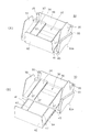
排出口紙案内26の下方には、排出口紙案内26を伝って下降したロール紙100を受ける排出トレイ30(外付部材)が設けられている。排出トレイ30は、排出口紙案内26の下方に位置してロール紙100を収容する受け部32を構成する排出トレイ本体31と、排出トレイ本体31に対してスライド可能に取り付けられたスライド部材41と、を備えて構成される。排出トレイ本体31の上部には係合ピン35(ヒンジ)が設けられ、この係合ピン35はロール紙カバー20に設けられた軸受け(図示略)に係合する。排出トレイ30は、係合ピン35を介して回動自在にロール紙カバー20の前面に取り付けられている。
Below the discharge
排出トレイ本体31の受け部32は、排出口紙案内26と同様に下向きの斜面と、この斜面の両側端に立設された一対の側壁33と、紙止め板42とで囲まれる空間である。また、スライド部材41の下端は、受け部32の下端に位置してロール紙100の落下を防ぐ紙止め板42となっている。スライド部材41を排出トレイ本体31に対してスライドさせることで、紙止め板42を移動させ、受け部32の長さを変化させることができる。
上述のように、排出口25からはカッターユニット80によって切断されたロール紙100の切片が排出される。この切片は排出口紙案内26の斜面を伝って下降し、受け部32に落下する。ここで、ロール紙100の切片は排出口紙案内26の斜面の下端から受け部32へ落下する際に回転することがあるが、受け部32の長さを適度な長さに調整すると、ロール紙100の切片が裏返ることなく受け部32に蓄積される。この場合、ロール紙100の切片が裏返しにならず、画像が印刷された面が上を向いているので、この切片が受け部32に蓄積された状態で、印刷された画像を視認できる。
The receiving
As described above, the section of the
図2に示すように、スライド部材41を最も本体10側にスライドさせた状態では、スライド部材41の先端43aがロール紙カバー20の前面に接する。スライド部材41を排出トレイ本体31から前方へ引き出すと、先端43aがロール紙カバー20の前面から離れ、排出トレイ本体31の本体側斜面36がロール紙カバー20の前面に接する。
ここで、インクジェットプリンター1の設置面に対する紙蓄積面34の角度は、先端43aがロール紙カバー20に接している状態では小さく、本体側斜面36がロール紙カバー20に接している状態では、やや大きくなる。
つまり、紙止め板42が上方に位置している状態では、先端43aがロール紙カバー20に当たることで、紙蓄積面34の角度が小さくなっている。この状態は、短い長さで切断されたロール紙100の切片を受ける場合に好適である。紙止め板42が排出口25に近く、紙蓄積面34の角度が小さいため、ロール紙100の切片が裏返ったり受け部32から飛び出したりしない等の利点がある。
一方、スライド部材41を下方に引き出すと、先端43aがロール紙カバー20から離れることで、紙蓄積面34の角度が急峻になる。この状態は、受け部32が長いためにロール紙100の長い切片を受ける場合に好適である。紙蓄積面34が急な角度であるために長い切片が排出口25近傍で詰まることがなく、確実に紙止め板42の位置まで落とすことができる等の利点がある。
このように、排出トレイ30は、受け部32の長さを変えるためにスライド部材41をスライドさせることにより、紙蓄積面34の角度が自動的に変化する構成を有する。
As shown in FIG. 2, the
Here, the angle of the
That is, in the state in which the
On the other hand, when the
Thus, the
ロール紙カバー20の下端は、ヒンジ部23(図2)を中心としてインクジェットプリンター1の本体10に回動可能に支持されており、ロール紙カバー20の上端が下向きに回動するように、開放できる。ロール紙カバー20は、通常時に開放しないよう図示しないロック機構により閉状態で保持されている。ロール紙カバー20の上端に設けられた開放レバー22の操作により、ロック機構が解除され、ロール紙カバー20を開くことができる。
The lower end of the
図2に示すように、インクジェットプリンター1の本体10は、底部フレーム51、後部フレーム52、及び上部フレーム53からなるフレームを有する。底部フレーム51はインクジェットプリンター1の下部を支持する板状のフレームであって、設置面に接する複数の脚54が底部フレーム51に固定されている。後部フレーム52は、底部フレーム51に立設され、後部フレーム52の上部には上部フレーム53が固定されている。後部フレーム52の背面側には、インクジェットプリンター1を制御する各種制御回路が実装された制御基板55が支持されている。
ロール紙100を収容するロール紙収容部10aは、底部フレーム51と上部フレーム53との間に確保された空間であり、このロール紙収容部10aの底部にはロール紙支持ローラー61及びロール紙支持バー62が設けられている。ロール紙支持ローラー61は本体10のフレームに対して回転自在に取り付けられたローラーであり、ロール紙支持バー62とともに、ロール紙100が容易に回転可能なように、ロール紙100を下方から支持する。また、ロール紙収容部10aの左右側面には、ロール紙100の側面に接してロール紙100を安定させるロール紙押さえ63が配設されている。
As shown in FIG. 2, the
The roll
ロール紙収容部10aに収容されたロール紙100は上方に引き出される。ロール紙収容部10aの上部には、第1搬送ローラー64と第2搬送ローラー65とが対向して配置され、引き出されたロール紙100を挟んで上方へ搬送する。第1搬送ローラー64は、搬送モーター(図示略)により駆動され、第2搬送ローラー65は、第1搬送ローラー64の回転に追従する従動ローラーである。
第1搬送ローラー64及び第2搬送ローラー65の上方には、ロール紙100を前方へ案内する紙案内69が設けられ、紙案内69に対向して第3搬送ローラー66が配置されている。第3搬送ローラー66は、上述の搬送モーター(図示略)により駆動され、ロール紙100を前方へ搬送する。
The
A
紙案内69の前方には、紙支持ユニット60が配置されている。紙支持ユニット60は、上部フレーム53によって支持され、ロール紙100に画像を記録して排出口25から排出するまでの一連の処理を行う各部を備えている。
紙支持ユニット60は、第3搬送ローラー66により前方に搬送されたロール紙100を搬送する第4搬送ローラー67及び第5搬送ローラー68と、ロール紙100を下方から支持するプラテン71と、このプラテン71の上方からロール紙100にインクを吐出して画像を記録する記録ヘッド70と、記録ヘッド70により画像が記録されたロール紙100を切断するカッターユニット80と、を備えている。
A
The
第4搬送ローラー67は搬送経路Pの上方に位置し、第5搬送ローラー68はロール紙100の搬送経路Pの下方に位置して、互いに対向して配置されている。第5搬送ローラー68は上述した搬送モーター(図示略)により駆動され、第4搬送ローラー67は第5搬送ローラー68に追従する従動ローラーである。
第4搬送ローラー67及び第5搬送ローラー68の上方には、本体10の幅方向に延びるガイド軸72が設けられ、このガイド軸72に沿って、記録ヘッド70が、ヘッド駆動モーター(図示略)の動作によって、ロール紙100の幅方向に往復走査される。記録ヘッド70は、通常時はインクカートリッジ収容扉16(図1)側に設けられた待避位置にあるため、図2中では仮想線で示す。
The
A
記録ヘッド70は、ロール紙100の表面にインクを噴射して画像を記録するインクジェット式の記録ヘッドである。詳細には、インクカートリッジ収容扉16の奥に収容されたインクカートリッジ(図示略)からインク供給管73を介して供給されるインクを、例えばピエゾ素子を利用した噴射機構により、噴射口からロール紙100へ噴射する。
この記録ヘッド70とプラテン71との間を通ったロール紙100は、第4搬送ローラー67及び第5搬送ローラー68による搬送力によって、搬送経路Pに沿って前方へ搬送され、カッターユニット80の位置に至る。
The
The
カッターユニット80(カッター部)は、搬送経路Pの下方に埋設設置された固定刃81と、この固定刃81に摺合うように搬送経路Pの上方に設置された可動刃82と、を備え、固定刃81と可動刃82とによってロール紙100を挟み込んで、ロール紙100のラベル用紙を剥離紙ごと切断する。可動刃82には、カッター駆動モーター83と、カッター駆動モーター83の回転力により可動刃82を上下に移動させるカッター駆動ローラー84とが配設され、これらカッター駆動モーター83及びカッター駆動ローラー84の動作によってロール紙100が切断される。
そして、カッターユニット80によりロール紙100が切断された際に、ロール紙100の先端が排出口25から外に出ている場合には、この部分の重みにより、切断されたロール紙100の切片は排出口紙案内26に沿って落下する。
The cutter unit 80 (cutter unit) includes a fixed
When the
制御基板55に実装された制御回路は、インクジェットプリンター1が備える搬送モーター(図示略)、ヘッド駆動モーター(図示略)、記録ヘッド70の噴射機構、及び、カッター駆動モーター83を駆動して、ロール紙100の搬送、ロール紙100への画像の記録、及び、ロール紙100の切断に係る一連の動作を実行する。
また、図1に示すように、インクカートリッジ収容扉16の下方にはインクジェットプリンター1の電源のオン/オフを切り替えるための電源スイッチ91が配置され、前面上部パネル13にはカッターユニット80(図2)によりロール紙100をカットさせるカットボタン92と、ロール紙100を所望の量だけ搬送させるためのフィードボタン93とが配置されている。
制御基板55に実装された制御回路は、電源スイッチ91の操作に従って電源がオンとなって動作を開始し、インクジェットプリンター1に外部接続されたホストコンピューター等との間でデータや制御信号を送受信し、このホストコンピューター等の制御に従ってロール紙100に画像を記録する。また、カットボタン92の操作時に、制御回路は、ホストコンピューター等により指示された切断動作とは別に、カッター駆動モーター83を動作させ、フィードボタン93の押下時にはホストコンピューター等により指示された搬送動作とは別に、フィードボタン93が押下されている間、搬送モーター(図示略)を動作させる。
また、インクジェットプリンター1の前面には、図1に示すようにインジケーター94が設けられている。インジケーター94は、複数のLEDを備え、制御基板55に実装された制御回路は、インジケーター94の複数のLEDの点灯状態を、点灯、点滅、消灯等に切り替えることによって、インクジェットプリンター1の動作状態や、インクカートリッジ交換の案内等の各種メッセージを表示出力する。
A control circuit mounted on the
As shown in FIG. 1, a
The control circuit mounted on the
Further, an
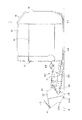
図3は、インクジェットプリンター1においてロール紙カバー20を開いた状態を示す斜視図である。
インクジェットプリンター1のロール紙カバー20は、開放レバー22の操作によってロック状態が解除されると、その下端部を中心として前方に回動して、図3に示すように開かれる。図3の開状態では、ロール紙カバー20とともに、第2搬送ローラー65、第5搬送ローラー68、紙案内69、及びプラテン71等が前方へせり出し、ロール紙収容部10aが露出する。
ロール紙100を装填する場合、図3の開状態でロール紙100をロール紙収容部10aに投入し、ロール紙100の先端を引き出して第5搬送ローラー68及びプラテン71の上に載せて、ロール紙カバー20を閉める。ここで、ロール紙カバー20が閉まる際に、ロール紙100は、プラテン71と記録ヘッド70との間、第5搬送ローラー68と第4搬送ローラー67との間、紙案内69と第3搬送ローラー66との間、及び、第2搬送ローラー65と第1搬送ローラー64との間に挟まれる。従って、インクジェットプリンター1においては、ロール紙100の先端を引き出した状態でロール紙収容部10aに投入し、ロール紙カバー20を閉めるだけで、容易に、図2の搬送経路Pに沿ってロール紙100をセットできる。
FIG. 3 is a perspective view showing a state in which the
When the locked state is released by the operation of the
When the
図3に示す開状態では、ロール紙カバー20が前方に倒れるように回動するので、ロール紙カバー20に取り付けられた排出トレイ30は、インクジェットプリンター1の設置面に接する。ここで、排出トレイ30は、ロール紙カバー20の開動作の障害にならないように、インクジェットプリンター1の設置面に当たってからも容易に回動するようになっている。
In the open state shown in FIG. 3, the
図4は、排出トレイ30の構成を示す斜視図であり、(A)は紙止め板42を排出トレイ本体31に収納した状態を示し、(B)は紙止め板42を引き出した状態を示す。
排出トレイ30の紙止め板42は、排出トレイ本体31に対してスライド可能に構成され、図4(A)に示す状態と図4(B)に示す状態との間の任意の長さに引き出すことができる。
スライド部材41の側面にはラック44が形成され、排出トレイ本体31の下端面にはラック44に係合してスライド部材41を任意の引き出し位置で固定するロック部材45が設けられている。紙止め板42の引き出し位置は、排出口25から排出されるロール紙100の切片の長さに応じて、適宜調整することが好ましい。
また、排出トレイ本体31の紙蓄積面34には、排出口25から排出されたロール紙100の切片を紙止め板42までスムーズに流すためのリブ37が形成され、スライド部材41にもリブ47が形成されている。
4A and 4B are perspective views showing the configuration of the
The
A
Further, a
排出トレイ30の側面を構成する側壁33の下部には、接触部33aが形成されている。接触部33aは、ロール紙カバー20を閉状態(図1)から開状態(図3)に移行させる間に、インクジェットプリンター1の設置面に接する部分であり、本実施形態では、側方から見て鈍角の突起となっている。
A
図5〜図8はインクジェットプリンター1の側面図であり、図5は閉状態を示し、図8は開状態を示し、図6及び図7は閉状態から開状態に移行する過程を示す。図5〜図8の各図において、インクジェットプリンター1の設置面を符号Aで示す。
図5に示す閉状態では、排出トレイ30の下端はスライド部材41であり、ロール紙カバー20を開くと、最初にスライド部材41の下端(第1の接触部)が設置面Aに接する。さらにロール紙カバー20が開くと、係合ピン35を中心にして排出トレイ30が回動し、図6に示すように接触部33a(第2の接触部)が設置面Aに接する。図6の状態では、接触部33aは係合ピン35の直下(仮想線V1)よりも、インクジェットプリンター1から離れた側にある。このため、図6の状態で、ロール紙カバー20をさらに回動させるために下向きの力が加わると、排出トレイ30はさらに回動して図7の状態に移行する。
5 to 8 are side views of the
In the closed state shown in FIG. 5, the lower end of the
図7の状態では、排出トレイ30のスライド部材41及び接触部33aが設置面Aに接している。排出トレイ30がスライド部材41及び接触部33aの2カ所で設置面Aに接しているため安定性が高いように見えるが、スライド部材41及び接触部33aはいずれも、係合ピン35の直下(仮想線V1)よりも、インクジェットプリンター1から離れた側にある。このため、図7の状態でロール紙カバー20に下向きの力が加わると、排出トレイ30はさらに回動する。
図8の状態では、排出トレイ30の先端43aが設置面Aに接し、接触部33aが設置面Aから離れて浮いている。この状態は、側壁33が排出口紙案内26に当接しているため、排出トレイ30の回動範囲の限界であり、ロール紙カバー20の最大開口状態である。図8の状態ではロール紙カバー20はほぼ設置面Aに平行になるまで開いており、ロール紙100の装填・交換を行うために十分な開口量が確保されている。
In the state of FIG. 7, the
In the state of FIG. 8, the
このように、本発明を適用した実施形態に係るインクジェットプリンター1によれば、本体10の前面に設けたロール紙カバー20を開く過程で、ロール紙カバー20に設けた排出トレイ30が設置面Aに接したときに、この接触位置が係合ピン35の直下からずれている。つまり、係合ピン35が構成するヒンジの直下から外れた位置であるため、さらにロール紙カバー20を開く力が加わると、この力に応じて排出トレイ30がさらに回動する。従って、排出トレイ30が設置面Aに接触した状態で安定してロール紙カバー20が開かなくなる事態を回避し、排出トレイ30をスムーズに回動させてロール紙カバー20を十分な開口量に開くことができるので、ロール紙カバー20の操作性を損なうことなく排出トレイ30を配設できる。これにより、排出トレイ30の設置位置に係る制限を回避し、設計上の自由度を高めることができる。
Thus, according to the
排出トレイ30に接触する接触部は、スライド部材41、接触部33a及び先端43aのように設置面Aに点接触してもよいし、線状に接触する接触部を設けてもよく、設置面Aに接触する面を排出トレイ30に設けてもよい。図7に示したように、接触部33aと先端43aの両方が設置面Aに接触しても、接触した部分の全てが係合ピン35の直下から外れた位置にある場合には、係合ピン35を中心として排出トレイ30を回動させ、ロール紙カバー20を大きく開くことができる。
The contact portion that comes into contact with the
さらに、排出トレイ30は、ロール紙カバー20が閉状態から開状態になる過程で最初に設置面Aに接するスライド部材41と、スライド部材41が設置面Aに接した後にロール紙カバー20が開くことで設置面Aに接する接触部33aと、を有し、スライド部材41及び接触部33aのいずれもが係合ピン35の直下から外れた位置で設置面Aに接するので、排出トレイ30を設置面Aに接した後も回動させることが可能になり、ロール紙カバー20を十分な開口量に開くことができる。さらに排出トレイ30が回動した場合に設置面Aに接する先端43aもまた、係合ピン35の直下よりも本体10から離れた位置で設置面Aに接する。また、ロール紙100を収容する際に開く必要のあるロール紙収容部10aのカバーであるロール紙カバー20に排出トレイ30を取り付けながら、ロール紙カバー20の十分な開口量を確保できる。
従って、設置面Aに向けて大きく開かれるロール紙カバー20の開閉の障害とならないように、排出トレイ30等の付属物(外付部材)を設けることができるので、インクジェットプリンター1における各種部材の取り付け位置の自由度が高まる。
Further, the
Therefore, since attachments (external members) such as the
なお、上記実施形態は本発明を適用した一態様を示すものであって、本発明は上記実施形態に限定されない。例えば、上記各実施形態では、インクジェットプリンター1の前面に設けられたロール紙カバー20に排出トレイ30を取り付けた構成を例に挙げ、この排出トレイ30が、ロール紙カバー20の開動作時に回動する構成について説明したが、本発明はこれに限定されるものではなく、インクジェットプリンター1の側面に設けられた回動可能な開閉部であればロール紙カバー20に限定されず、また、この開閉部に取り付けられる部材は排出トレイ30に限定されない。例えば、インクカートリッジ収容扉16に何らかの付属物(インクカートリッジの付属品や説明書のホルダーなど)を設けた場合に、この付属物がインクカートリッジ収容扉16の開動作時に回動するものとしてもよい。また、インクジェットプリンター1の側面や背面に開閉部を設け、この開閉部に付属物を設けた構成に本発明を適用することも勿論可能である。
また、上記実施形態では、カッターユニット80によってロール紙100が切断され、この切片が排出トレイ30に蓄積される例について説明したが、本発明はこれに限定されず、インクジェットプリンター1がロール紙100を切断しないで排出口25から排出してもよいし、勿論、カッターユニット80を備えていないプリンターに本発明を適用してもよい。さらに、上記実施形態の排出トレイ30は、排出トレイ本体31の接触部33aが点状に設置面に接する例について説明したが、この接触部33aが設置面に接した状態で、接した部分が係合ピン35の直下から外れていれば、接触部33aが平面で構成されていて、この平面が設置面に完全に接触してもよいし、接触部33aが設置面に接する領域が直線状であってもよい。
また、上記実施形態において、記録媒体としてラベル用紙のロール紙を用いる場合について説明したが、記録媒体はラベル用紙に限らないし、カットシートや連続シートを用いてもよい。また、画像記録装置としてインクを吐出して画像を記録するインクジェットプリンター1を例に挙げて説明したが、本発明は、サーマルヘッドによって感熱ロール紙に画像を記録するサーマルプリンターや、ドットインパクトプリンター、熱昇華型プリンター等の各種プリンター、及び、これらのプリンターを機構部品として備えた他の電子機器に対しても適用可能である。
In addition, the said embodiment shows the one aspect | mode which applied this invention, Comprising: This invention is not limited to the said embodiment. For example, in each of the above embodiments, a configuration in which the
Moreover, although the
In the above-described embodiment, the case where the roll paper of the label paper is used as the recording medium has been described. However, the recording medium is not limited to the label paper, and a cut sheet or a continuous sheet may be used. In addition, the
1…インクジェットプリンター(画像記録装置)、10…本体、10a…ロール紙収容部(記録媒体収容部)、20…ロール紙カバー(開閉カバー)、22…開放レバー、23…ヒンジ部、25…排出口、26…排出口紙案内、30…排出トレイ(外付部材)、31…排出トレイ本体、32…受け部、33…側壁、33a…接触部(第2の接触部)、34…紙蓄積面、35…係合ピン(ヒンジ)、36…本体側斜面、41…スライド部材(第1の接触部)、42…紙止め板、43a…先端、54…脚、55…制御基板、60…紙支持ユニット、70…記録ヘッド、71…プラテン、80…カッターユニット(カッター部)、100…ロール紙(記録媒体)、A…設置面、P…搬送経路。
DESCRIPTION OF
Claims (7)
前記開閉カバーの前記係合部材に係合される被係合部材を有し、前記被係合部材を介して回動する外付部材と、を備え、
前記外付部材は、前記開閉カバーが閉状態から開状態になる過程で前記被係合部材の直下よりも前記本体から離れた側で前記設置面に接し、前記設置面に接した後の前記開閉カバーが開かれる過程で前記被係合部材を中心にして回動することを特徴とする画像記録装置。 A recording unit that records an image on a recording medium, an open / close cover that has an engaging member and opens toward the installation surface, and a main body installed on the installation surface;
An engagement member that is engaged with the engagement member of the opening and closing cover, and an external member that rotates through the engagement member,
The external member is in contact with the installation surface on the side farther from the main body than just below the engaged member in the process in which the open / close cover is changed from the closed state to the open surface, and after the contact with the installation surface An image recording apparatus, wherein the image recording apparatus rotates about the engaged member in the process of opening the opening / closing cover.
前記第1の接触部及び第2の接触部は、前記被係合部材の直下から外れた位置で前記設置面に接する請求項1に記載の画像記録装置。 The external member includes a first contact portion that first contacts the installation surface in a process in which the opening / closing cover is changed from a closed state to an open state, and the installation surface after the first contact portion contacts the installation surface. A second contact portion in contact with
The first contact portion and second contact portion, the image recording apparatus according to claim 1 in contact with the installation surface at a position deviated from immediately below the engaged member.
前記開閉カバーは、前記記録媒体収容部のカバーである請求項1から4のいずれか1項に記載の画像記録装置。 It said body has a recording medium housing portion for housing the recording medium member,
5. The image recording apparatus according to claim 1, wherein the opening / closing cover is a cover of the recording medium housing portion.
前記外付部材は、前記切断部により切断された前記記録媒体を受ける排出トレイである請求項1から5のいずれか1項に記載の画像記録装置。 A discharge port for discharging the recording medium from the main body, and a cutting unit for cutting the recording medium discharged from the discharge port;
The image recording apparatus according to claim 1, wherein the external member is a discharge tray that receives the recording medium cut by the cutting unit.
本体の一側面に配設されて設置面に向けて開く開閉カバーと、
前記開閉カバーが有する係合部材に係合される被係合部材を有し、前記被係合部材で回動するとともに、前記記録部で記録された前記記録媒体を収容する排出トレイと、を備え、
前記開閉カバーが閉状態から開状態になる過程で前記排出トレイが前記設置面で接したときに、前記排出トレイが前記設置面に接した位置の直上よりも前記本体側に前記被係合部材を位置させ、
前記排出トレイが、前記設置面で接し、前記設置面に接した後の前記開閉カバーが開かれる過程で前記被係合部材を中心にして回動可能とすることを特徴とする排出トレイの支持構造。
A recording unit for recording an image on a recording medium;
An opening / closing cover disposed on one side of the main body and opening toward the installation surface;
A material having an engagement member that is engaged with the engaging member to which the cover has, the with pivots engaged member, a discharge tray for accommodating the recording medium recorded by said recording unit, With
When the open-close cover said discharge tray in a process consisting of a closed state to an open state in contact with the installation surface, the engaged portion on the main body side from immediately above the position where the discharge tray is in contact with the installation surface Position the material ,
A support for the discharge tray, wherein the discharge tray is in contact with the installation surface and is rotatable about the engaged member in the process of opening the opening / closing cover after contacting the installation surface. Construction.
Priority Applications (1)
| Application Number | Priority Date | Filing Date | Title |
|---|---|---|---|
| JP2009011566A JP5402014B2 (en) | 2009-01-22 | 2009-01-22 | Image recording apparatus and discharge tray support structure |
Applications Claiming Priority (1)
| Application Number | Priority Date | Filing Date | Title |
|---|---|---|---|
| JP2009011566A JP5402014B2 (en) | 2009-01-22 | 2009-01-22 | Image recording apparatus and discharge tray support structure |
Publications (3)
| Publication Number | Publication Date |
|---|---|
| JP2010168157A JP2010168157A (en) | 2010-08-05 |
| JP2010168157A5 JP2010168157A5 (en) | 2012-01-12 |
| JP5402014B2 true JP5402014B2 (en) | 2014-01-29 |
Family
ID=42700672
Family Applications (1)
| Application Number | Title | Priority Date | Filing Date |
|---|---|---|---|
| JP2009011566A Expired - Fee Related JP5402014B2 (en) | 2009-01-22 | 2009-01-22 | Image recording apparatus and discharge tray support structure |
Country Status (1)
| Country | Link |
|---|---|
| JP (1) | JP5402014B2 (en) |
Family Cites Families (1)
| Publication number | Priority date | Publication date | Assignee | Title |
|---|---|---|---|---|
| JP4631586B2 (en) * | 2004-08-09 | 2011-02-16 | セイコーエプソン株式会社 | Label printer |
-
2009
- 2009-01-22 JP JP2009011566A patent/JP5402014B2/en not_active Expired - Fee Related
Also Published As
| Publication number | Publication date |
|---|---|
| JP2010168157A (en) | 2010-08-05 |
Similar Documents
| Publication | Publication Date | Title |
|---|---|---|
| JP5212136B2 (en) | Image recording device | |
| US7553098B2 (en) | Roll paper printer | |
| JP3873327B2 (en) | Inkjet printer with replaceable ink cartridge | |
| US8157462B2 (en) | Operating mechanism for a printer cover, and a printer | |
| US20110058884A1 (en) | Tape cassette | |
| KR100949631B1 (en) | Printer, printer controlling method and computer readable recording medium for storing controlling program | |
| JP6924408B2 (en) | Cutting mechanism and printing equipment | |
| CN115362067A (en) | Printing apparatus | |
| CN113613908B (en) | Printer and printing method | |
| US9156637B2 (en) | Tray unit and image recording device | |
| JP6929519B2 (en) | Cutting mechanism and printing equipment | |
| JP5402014B2 (en) | Image recording apparatus and discharge tray support structure | |
| JP2011110812A (en) | Recording device and recording medium supplying structure for the recording device | |
| JP5089343B2 (en) | Paper cutting assist structure in printing device | |
| JP2011110813A (en) | Recording device and recording medium supplying structure for the recording device | |
| JP5609262B2 (en) | Transport roller cleaning mechanism and printer | |
| JP5293228B2 (en) | Recording device | |
| JP4033211B2 (en) | Printer | |
| JP2010137366A (en) | Inkjet recording apparatus | |
| JP4802612B2 (en) | Recording device | |
| US20220314668A1 (en) | Recording apparatus | |
| JP3965860B2 (en) | Inkjet printer | |
| JP2009248316A (en) | Recording device | |
| JP5776211B2 (en) | Recording media cassette | |
| JP4506800B2 (en) | Printer |
Legal Events
| Date | Code | Title | Description |
|---|---|---|---|
| A521 | Request for written amendment filed |
Free format text: JAPANESE INTERMEDIATE CODE: A523 Effective date: 20111117 |
|
| A621 | Written request for application examination |
Free format text: JAPANESE INTERMEDIATE CODE: A621 Effective date: 20111117 |
|
| RD02 | Notification of acceptance of power of attorney |
Free format text: JAPANESE INTERMEDIATE CODE: A7422 Effective date: 20111117 |
|
| A977 | Report on retrieval |
Free format text: JAPANESE INTERMEDIATE CODE: A971007 Effective date: 20130110 |
|
| A131 | Notification of reasons for refusal |
Free format text: JAPANESE INTERMEDIATE CODE: A131 Effective date: 20130115 |
|
| A521 | Request for written amendment filed |
Free format text: JAPANESE INTERMEDIATE CODE: A523 Effective date: 20130314 |
|
| A131 | Notification of reasons for refusal |
Free format text: JAPANESE INTERMEDIATE CODE: A131 Effective date: 20130423 |
|
| A521 | Request for written amendment filed |
Free format text: JAPANESE INTERMEDIATE CODE: A523 Effective date: 20130620 |
|
| A131 | Notification of reasons for refusal |
Free format text: JAPANESE INTERMEDIATE CODE: A131 Effective date: 20130716 |
|
| A521 | Request for written amendment filed |
Free format text: JAPANESE INTERMEDIATE CODE: A523 Effective date: 20130906 |
|
| TRDD | Decision of grant or rejection written | ||
| A01 | Written decision to grant a patent or to grant a registration (utility model) |
Free format text: JAPANESE INTERMEDIATE CODE: A01 Effective date: 20131001 |
|
| A61 | First payment of annual fees (during grant procedure) |
Free format text: JAPANESE INTERMEDIATE CODE: A61 Effective date: 20131014 |
|
| R150 | Certificate of patent or registration of utility model |
Ref document number: 5402014 Country of ref document: JP Free format text: JAPANESE INTERMEDIATE CODE: R150 |
|
| S531 | Written request for registration of change of domicile |
Free format text: JAPANESE INTERMEDIATE CODE: R313531 |
|
| R350 | Written notification of registration of transfer |
Free format text: JAPANESE INTERMEDIATE CODE: R350 |
|
| LAPS | Cancellation because of no payment of annual fees |