JP5399015B2 - Fuel nozzle for gas turbine engine and method of making the same - Google Patents
Fuel nozzle for gas turbine engine and method of making the same Download PDFInfo
- Publication number
- JP5399015B2 JP5399015B2 JP2008190403A JP2008190403A JP5399015B2 JP 5399015 B2 JP5399015 B2 JP 5399015B2 JP 2008190403 A JP2008190403 A JP 2008190403A JP 2008190403 A JP2008190403 A JP 2008190403A JP 5399015 B2 JP5399015 B2 JP 5399015B2
- Authority
- JP
- Japan
- Prior art keywords
- fuel nozzle
- nozzle assembly
- assembly
- secondary fuel
- exemplary embodiment
- Prior art date
- Legal status (The legal status is an assumption and is not a legal conclusion. Google has not performed a legal analysis and makes no representation as to the accuracy of the status listed.)
- Expired - Fee Related
Links
Images


Classifications
-
- F—MECHANICAL ENGINEERING; LIGHTING; HEATING; WEAPONS; BLASTING
- F23—COMBUSTION APPARATUS; COMBUSTION PROCESSES
- F23R—GENERATING COMBUSTION PRODUCTS OF HIGH PRESSURE OR HIGH VELOCITY, e.g. GAS-TURBINE COMBUSTION CHAMBERS
- F23R3/00—Continuous combustion chambers using liquid or gaseous fuel
- F23R3/28—Continuous combustion chambers using liquid or gaseous fuel characterised by the fuel supply
-
- F—MECHANICAL ENGINEERING; LIGHTING; HEATING; WEAPONS; BLASTING
- F02—COMBUSTION ENGINES; HOT-GAS OR COMBUSTION-PRODUCT ENGINE PLANTS
- F02C—GAS-TURBINE PLANTS; AIR INTAKES FOR JET-PROPULSION PLANTS; CONTROLLING FUEL SUPPLY IN AIR-BREATHING JET-PROPULSION PLANTS
- F02C7/00—Features, components parts, details or accessories, not provided for in, or of interest apart form groups F02C1/00 - F02C6/00; Air intakes for jet-propulsion plants
- F02C7/22—Fuel supply systems
-
- F—MECHANICAL ENGINEERING; LIGHTING; HEATING; WEAPONS; BLASTING
- F23—COMBUSTION APPARATUS; COMBUSTION PROCESSES
- F23R—GENERATING COMBUSTION PRODUCTS OF HIGH PRESSURE OR HIGH VELOCITY, e.g. GAS-TURBINE COMBUSTION CHAMBERS
- F23R3/00—Continuous combustion chambers using liquid or gaseous fuel
- F23R3/28—Continuous combustion chambers using liquid or gaseous fuel characterised by the fuel supply
- F23R3/34—Feeding into different combustion zones
-
- Y—GENERAL TAGGING OF NEW TECHNOLOGICAL DEVELOPMENTS; GENERAL TAGGING OF CROSS-SECTIONAL TECHNOLOGIES SPANNING OVER SEVERAL SECTIONS OF THE IPC; TECHNICAL SUBJECTS COVERED BY FORMER USPC CROSS-REFERENCE ART COLLECTIONS [XRACs] AND DIGESTS
- Y10—TECHNICAL SUBJECTS COVERED BY FORMER USPC
- Y10T—TECHNICAL SUBJECTS COVERED BY FORMER US CLASSIFICATION
- Y10T29/00—Metal working
- Y10T29/49—Method of mechanical manufacture
- Y10T29/49428—Gas and water specific plumbing component making
- Y10T29/49432—Nozzle making
Landscapes
- Engineering & Computer Science (AREA)
- Chemical & Material Sciences (AREA)
- Combustion & Propulsion (AREA)
- Mechanical Engineering (AREA)
- General Engineering & Computer Science (AREA)
- Gas Burners (AREA)
Description
本発明は、総括的にはガスタービンエンジンで使用するための燃焼システムに関し、より具体的には、ガスタービンエンジンで使用する燃料ノズルに関する。 The present invention relates generally to combustion systems for use with gas turbine engines, and more particularly to fuel nozzles for use with gas turbine engines.
ガスタービンエンジンで使用する少なくとも幾つかの公知の燃料ノズルアセンブリは、複数の構成要素から組立てられ、それらが完全に組立てられた時に一体構造の燃料ノズルアセンブリを形成する。公知の複数部品組立て燃料ノズルは、本体部とスリーブ部を含む。多くの構成要素が互いに結合されるので、ノズルアセンブリからの望ましくない流体漏れを防止するために、少なくとも幾つかの公知のノズルアセンブリは、互いに結合された構成要素間に複数のシールを含んでいる。より具体的には、少なくとも幾つかの公知のノズルアセンブリは、本体対スリーブシール、ウオータリップシール、拡散リップシール及び/又はピストンシールを使用している。それらの意図した効力にも拘わらず、それでもなお各シールは、ノズルアセンブリを通ってゆっくりと流れる加圧流体に曝された時又はガスタービンエンジンの燃焼システム内の高温度に曝された時に、漏れ発生可能性区域となるおそれがある。さらに、多くの構成要素を有する燃料ノズルアセンブリは一般的に、ガスタービンエンジン内の少数の構成要素を含むアセンブリよりも、その製作及び組立てに多くの時間及びコストを必要とする。
1つの態様では、燃料ノズルを製作する方法を提供する。本方法は、第1の端面、第2の端面及びそれらの間で延びる本体を含む単体構造の材料部分を準備するステップを含む。通路は、材料部分の中心線に沿って第1の端面から第2の端面まで延びるように製作される。本方法はさらに、第1の端面内に複数の同心に整列したチャネルを製作するステップと、第2の端面及び本体の外表面の少なくとも1つを貫通して通路及び複数のチャネルの1つの少なくとも1つまで延びる複数の入口を製作するステップを含む。 In one aspect, a method for fabricating a fuel nozzle is provided. The method includes providing a unitary material portion that includes a first end surface, a second end surface, and a body extending therebetween. The passage is fabricated to extend from the first end surface to the second end surface along the center line of the material portion. The method further includes fabricating a plurality of concentrically aligned channels in the first end face, passing through at least one of the second end face and the outer surface of the body, and at least one of the passage and the plurality of channels. Creating a plurality of inlets extending to one.
別の態様では、二次燃料ノズルアセンブリを提供する。本二次燃料ノズルアセンブリは、中央通路と該中央通路に各々が同心に整列した複数の通路とを有するノズル部と、該ノズル部に結合された単体構造ヘッド部とを含む。ヘッド部は、複数の入口を含み、複数の入口の各々は、複数のノズル通路の少なくとも1つと流体連通している。 In another aspect, a secondary fuel nozzle assembly is provided. The secondary fuel nozzle assembly includes a nozzle portion having a central passage and a plurality of passages concentrically aligned with the central passage, and a unitary structure head portion coupled to the nozzle portion. The head portion includes a plurality of inlets, each of the plurality of inlets being in fluid communication with at least one of the plurality of nozzle passages.
さらに別の態様では、ガスタービンエンジンで使用するための燃焼器アセンブリを提供する。本燃焼器アセンブリは、燃焼ゾーンと、該燃焼ゾーン内に結合された一次燃料ノズルアセンブリと、該燃焼ゾーン内に結合された二次燃料ノズルアセンブリとを含む。二次燃料ノズルアセンブリは、中央通路と該中央通路にほぼ同心に整列した複数の通路とを有するノズル部と、該ノズル部に結合された単体構造ヘッド部とを含む。ヘッド部は、複数の入口を含み、複数の入口の各々は、複数のノズル通路の少なくとも1つと流体連通している。 In yet another aspect, a combustor assembly for use with a gas turbine engine is provided. The combustor assembly includes a combustion zone, a primary fuel nozzle assembly coupled within the combustion zone, and a secondary fuel nozzle assembly coupled within the combustion zone. The secondary fuel nozzle assembly includes a nozzle portion having a central passage and a plurality of passages aligned substantially concentrically with the central passage, and a unitary head portion coupled to the nozzle portion. The head portion includes a plurality of inlets, each of the plurality of inlets being in fluid communication with at least one of the plurality of nozzle passages.
図1は、燃料ノズルアセンブリ200を含む例示的なガスタービンエンジン100の部分断面図である。ガスタービンエンジン100は、圧縮機(図示せず)、燃焼器102及びタービン104を含む。図1には、タービン104の第1段ノズル106のみを示している。この例示的な実施形態では、タービンは、複数のロータ(図示せず)を有する圧縮機に対して回転可能に結合され、それらロータは、単一の共通シャフト(図示せず)を介して互いに結合される。圧縮機は、吸入空気108を加圧した後に燃焼器102に吐出し、燃焼器102において、加圧空気は、該燃焼器102を冷却しかつ燃焼プロセスのための空気を供給する。より具体的には、燃焼器102に送られる空気108は、エンジン100内を通る空気の流れとほぼ反対の方向に流れる。この例示的な実施形態では、ガスタービンエンジン100は、エンジンケーシング(図示せず)の周りに円周方向に間隔を置いて配置された複数の燃焼器102を含む。より具体的には、この例示的な実施形態では、燃焼器102は、それに限定されないが、例えば缶−アニュラ型燃焼器である。
FIG. 1 is a partial cross-sectional view of an exemplary
この例示的な実施形態では、エンジン100は、各燃焼器102の出口端部112とタービン104の入口端部114との間で延びて燃焼ガス116をタービン104内に送る移行ダクト110を含む。さらに、この例示的な実施形態では、各燃焼器102は、ほぼ円筒形の燃焼器ケーシング118を含む。燃焼器ケーシング118は、それに限定されないが、例えばボルト(図示せず)、機械的ファスナ(図示せず)、溶接、及び/又は本明細書に説明したようにエンジン100を機能させるのを可能にするあらゆるその他の適当な結合手段を用いて、エンジンケーシングに結合される。この例示的な実施形態では、燃焼器ケーシング118の前端部120は、端部カバーアセンブリ122に結合される。端部カバーアセンブリ122は、例えば気体燃料、液体燃料、空気及び/又は水を燃焼器に送るための供給管、マニフォルド、バルブ、並びに/或いは本明細書に説明したようにエンジン100を機能させるのを可能にするあらゆるその他の構成要素を含む。
In the exemplary embodiment,
この例示的な実施形態では、ほぼ円筒形の流れスリーブ124は、該スリーブ124が燃焼器ケーシング118にほぼ同心に整列するように該ケーシング118内に結合される。燃焼ライナ126は、流れスリーブ124内にほぼ同心に結合される。より具体的には、燃焼ライナ126は、その後端部128において移行ダクト110に結合され、またその前端部130において燃焼ライナキャップアセンブリ132に結合される。流れスリーブ124は、その後端部134においてライナ126の外壁136に結合され、またその前端部138において燃焼器ケーシング118に結合される。それに代えて、スリーブ124は、エンジン100を本明細書に説明したように機能させるのを可能にするあらゆるその他の適当な結合アセンブリを使用して、ケーシング118及び/又はライナ126に結合することができる。この例示的な実施形態では、空気通路140は、ライナ126と流れスリーブ124との間に形成される。流れスリーブ124は、その中に形成された複数の開口142を含み、これらの開口は、圧縮機からの加圧空気108が空気通路140に流入するのを可能にする。この例示的な実施形態では、空気108は、圧縮機から端部カバーアセンブリ122に向かうコア流れ(図示せず)の方向とは逆の方向に流れる。
In the exemplary embodiment, a generally
燃焼ライナ126は、一次燃焼ゾーン144、ベンチュリスロート領域146及び二次燃焼ゾーン148を含む。より具体的には、一次燃焼ゾーン144は、二次燃焼ゾーン148の上流に位置し、一次及び二次燃焼ゾーン144及び148は、ベンチュリスロート領域146によって隔てられる。ベンチュリスロート領域146は、それぞれの燃焼ゾーン144及び148の直径D1及びD2よりも一般的に小さい直径DVを有する。より具体的には、スロート領域146は、収束壁150と発散壁152とを含み、収束壁150は、直径D1からDVまでテーパしており、また発散壁152は、DVからD2まで拡大している。従って、ベンチュリスロート領域146は、二次燃焼ゾーン148から一次燃焼ゾーン144への逆火を減少させるのを可能にする空気力学的セパレータ又はアイソレータとして機能する。この例示的な実施形態では、一次燃焼ゾーン144は、それを貫通して形成された複数の開口154を含み、これらの開口は、空気108が空気通路140から一次燃焼ゾーン144に流入するのを可能にする。
The
さらに、この例示的な実施形態では、燃焼器102はまた、複数のスパークプラグ(図示せず)と複数のクロスファイヤ管(図示せず)とを含む。スパークプラグ及びクロスファイヤ管は、一次燃焼ゾーン144のライナ126内に形成されたポート(図示せず)を貫通して延びる。スパークプラグ及びクロスファイヤ管は、各燃焼器102内で燃料及び空気に点火して燃焼ガス116を発生させる。
Further, in this exemplary embodiment,
この例示的な実施形態では、少なくとも1つの二次燃料ノズルアセンブリ200は、端部カバーアセンブリ122に結合される。より具体的には、この例示的な実施形態では、燃焼器102は、1つの二次燃料ノズルアセンブリ200と複数の一次燃料ノズルアセンブリ156とを含む。より具体的には、この例示的な実施形態では、一次燃料ノズルアセンブリ156は、燃焼器102の中心線158の周りにほぼ円形列として配置され、また二次燃料ノズルアセンブリ200の中心線202(図2に示す)は、燃焼器中心線158に実質的に整列している。それに代えて、一次燃料ノズルアセンブリ156は、非円形列として配置することもできる。別の実施形態では、燃焼器102は、1つよりも多い又は少ない二次燃料ノズルアセンブリ200を含むことができる。本明細書では一次及び二次燃料ノズルアセンブリ156及び200についてのみ記述しているが、2つよりも多い又は少ないタイプのノズルアセンブリ或いはあらゆるタイプの燃料ノズルを燃焼器102内に含むことができる。この例示的な実施形態では、二次燃料ノズルアセンブリ200は、一次燃焼ゾーン144を貫通して延びる該二次ノズルアセンブリ200の一部分を実質的に囲む管アセンブリ160を含む。
In the exemplary embodiment, at least one secondary
一次ノズルアセンブリ156は、部分的に一次燃焼ゾーン144内に延び、また二次ノズルアセンブリ200は、一次燃焼ゾーンを貫通してスロート領域146の後方部分162内に延びる。従って、一次ノズルアセンブリ156から噴射された燃料(図示せず)は、実質的に一次燃焼ゾーン144内で燃焼し、また二次ノズルアセンブリ200から噴射された燃料(図示せず)は、実質的に二次燃焼ゾーン148内で燃焼する。
The
この例示的な実施形態では、燃焼器102は、燃料ノズルアセンブリ156及び200を介して該燃焼器102に燃料を供給するようになった燃料供給管(図示せず)に結合される。例えば、パイロット燃料(図示せず)及び/又はメイン燃料(図示せず)は、燃料ノズルアセンブリ156及び/又は200を通して供給することができる。この例示的な実施形態では、以下において一層詳しく述べるように、パイロット燃料及びメイン燃料は両方共、ノズルアセンブリ156及び200への燃料の移送を制御することによって、一次及び二次ノズルアセンブリ156及び200の両方を通して供給される。本明細書で使用する場合に、「パイロット燃料」というのは、パイロット火炎として使用する少量の燃料を意味しており、「メイン燃料」というのは、燃焼ガス116の大部分を発生するために使用する燃料を意味している。燃料は、天然ガス、石油製品類、石炭、バイオ燃料、並びに/或いは本明細書に説明したようにエンジン100を機能させるのを可能にする固体、液体及び/又は気体形態のあらゆるその他の燃料とすることができる。ノズルアセンブリ156及び/又は200を通る燃料流量を制御することによって、燃焼器102内の火炎(図示せず)は、燃焼器102の排出物(エミッション)及び/又は出力に影響を与えるような所定の形状、長さ及び/又は強さに調節することができる。
In the exemplary embodiment,
作動中に、空気108は、入口(図示せず)を通してエンジン100に流入する。空気108は、圧縮機内で加圧され、加圧空気108は、圧縮機から燃焼器102に向けて吐出される。空気108は、開口142を通して燃焼器102に流入し、空気通路140を通して端部カバーアセンブリ122に向けて送られる。空気通路140内を流れる空気108は、燃焼器入口端部164においてその流れ方向を強制的に反転されて、燃焼ゾーン144及び/又は148内にまた/或いはスロート領域146を通して送られる。燃料は、端部カバーアセンブリ122並びにノズルアセンブリ156及び/又は200を通して燃焼器102内に供給される。点火は、始めに制御システム(図示せず)がガスタービンエンジン100の始動シーケンスを開始した時に行われ、火炎が連続的に確立したら、スパークプラグは、一次燃焼ゾーン144からが引っ込められる。ライナ126の後端部128において、高温燃焼ガス116は、移行ダクト110及びタービンノズル106を通してタービン104に送られる。
During operation,
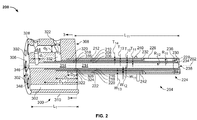
図2は、燃焼器102(図1に示す)で使用することができる例示的な二次燃料ノズルアセンブリ200の断面図である。図3は、二次燃料ノズルアセンブリ200で使用することができるヘッド部300の端面図である。
FIG. 2 is a cross-sectional view of an exemplary secondary
この例示的な実施形態では、燃料ノズルアセンブリ200は、ヘッド部300とノズル部204とを含む。ヘッド部300は、ノズルアセンブリ200を燃焼器102内に結合するのを可能にする。例えば、1つの実施形態では、ヘッド部300は、端部カバーアセンブリ122(図1に示す)に結合され、該ヘッド部300が燃焼器102の外部に位置しかつノズル部204が端部カバーアセンブリ122を貫通して延びるように、複数の機械的ファスナ168(図1に示す)を用いて端部カバーアセンブリ122に固定される。この例示的な実施形態では、ヘッド部300は、その各々がそれを通して機械的ファスナを受けるような寸法にされた複数の円周方向に間隔を置いて配置された孔302を含む。例えば図3には3つのみのファスナ孔302を示しているが、ヘッド部300は、燃料ノズルアセンブリ200を燃焼器102内に固定しかつ本明細書に説明したように機能させるのを可能にするあらゆる数の孔302を含むことができる。さらに、各孔302の内表面304は、実質的に滑らかであるように図示しているが、孔302はネジ付きとすることができる。これに加えて、各孔302は、ノズルアセンブリ200の中心線202にほぼ平行に延びるように図示しているが、孔302は、二次ノズルアセンブリ200を本明細書に説明したように機能させるのを可能にするあらゆる配向を有することができる。それに代えて、ヘッド部300は、機械的ファスナ168のみを用いて燃焼器102に結合されるように限定されるものではなく、二次ノズルアセンブリ200を本明細書に説明したように機能させるのを可能にするあらゆる結合手段を用いて燃焼器102に結合することができる。
In the exemplary embodiment,
この例示的な実施形態では、ヘッド部300は、ほぼ円柱形であり、第1のほぼ平坦な端面306、反対側の第2のほぼ平坦な端面308、及びそれらの間で延びるほぼ円柱形の本体310を含む。さらに、この例示的な実施形態では、ヘッド部300は、長さL1及び半径R1を有する。それに代えて、ヘッド部300は、ノズルアセンブリ200及び/又は燃焼器102を本明細書に説明したように機能させるのを可能にするあらゆるその他の適当な形状として形成することができる。さらに、この例示的な実施形態では、ヘッド部300は、単一の連続本体310のみとして形成される。より具体的には、ヘッド部300は、以下においてより詳しく述べるように、単一の中実材料片で形成される。
In the exemplary embodiment,
この例示的な実施形態では、ヘッド部300は、中央通路314と複数の同心に整列したチャネル316、318及び320とを含む。より具体的には、中央通路314は、中心線202に沿って第1の端面306から第2の端面308まで延び、半径R2を有する。さらに、この例示的な実施形態では、チャネル316、318及び320は各々、以下においてより詳しく述べるように、第2の端面308から第1の端面306に向けて部分的に延びる。この例示的な実施形態では、第1のチャネル316は、内側半径R3及び外側半径R4を有しかつ第2の端面308から測定して深さD1だけ延び、第2のチャネル318は、内側半径R5及び外側半径R6を有しかつ第2の端面308から測定して深さD2だけ延び、また第3のチャネル320は、内側半径R7及び外側半径R8を有しかつ第2の端面308から測定して深さD3だけ延びる。チャネル316、318及び320の配向の故に、第1のチャネル316は、内側半径R3と外側半径R4との間の差にほぼ等しい幅W1を有し、第2のチャネル318は、内側半径R6と外側半径R6との間の差にほぼ等しい幅W2を有し、また第3のチャネル320は、内側半径R7と外側半径R8との間の差にほぼ等しい幅W3を有する。この例示的な実施形態では、深さD1は、深さD2よりも深く、深さD2は、深さD3よりも深い。さらに、この例示的な実施形態では、半径は、R2<R3<R4<R5<R6<R7<R8<R1となるような寸法にされる。
In the exemplary embodiment,
この例示的な実施形態では、ヘッド部300内の複数の同心に整列したチャネル分割壁322、324及び326は、チャネル316、318及び/又は320並びに/或いは中央通路314を形成する。より具体的には、この例示的な実施形態では、中央通路314は、第1の分割壁322によって形成され、第1のチャネル316は、第1の分割壁322及び第2の分割壁324間に形成され、第2のチャネル318は、第2の分割壁324及び第2の分割壁326間に形成され、また第3のチャネル320は、第3の分割壁326及び本体310間に形成される。第1の分割壁322は、厚さT1を有し、第2の分割壁326は、厚さT2を有し、また第3の分割壁326は、厚さT3を有する。この例示的な実施形態では、壁厚さT1、T2及びT3は、互いにほぼ等しい。それに代えて、厚さT1、T2及び/又はT3は、等しくないようにすることもできる。
In the exemplary embodiment, a plurality of concentrically aligned
この例示的な実施形態では、ヘッド部300はまた、複数の半径方向入口328、330、332及び334を含む。第1の半径方向入口328は、本体310を貫通して中央通路314まで延び、第2の半径方向入口330は、本体310を貫通して第1のチャネル316まで延び、第3の半径方向入口332は、本体310を貫通して第2のチャネル318まで延び、また第4の半径方向入口334は、本体310を貫通して第3のチャネル320まで延びる。従って、第1の半径方向入口328の長さL11は、半径R1と半径R8との間の差にほぼ等しく、第2の半径方向入口330の長さL12は、半径R1と半径R5との間の差にほぼ等しく、第3の半径方向入口332の長さL13は、半径R1と半径R4との間の差にほぼ等しく、また第4の半径方向入口334の長さL14は、半径R1と半径R2との間の差にほぼ等しい。この例示的な実施形態では、1つのみの半径方向入口328、330、332及び/又は334がチャネル316、318及び/又は320並びに/或いは中央通路314と流体連通しているが、それに代えて各チャネル316、318及び/又は320並びに/或いは中央通路314は、1つよりも多い対応する半径方向入口を含むことができる。
In the exemplary embodiment,
この例示的な実施形態では、各半径方向入口328、330、332及び334は、そのそれぞれの入口長さL11、L12、L13及び/又はL14に沿ってほぼ一定の直径d1、d2、d3及びd4を有する。それに代えて、各半径方向入口328、330、332及び/又は334は、非円形断面形状及び/又は変化する直径を有するものとして形成することができる。より具体的には、半径方向入口328、330、332及び/又は334は、燃焼器102及び/又は二次燃料ノズルアセンブリ200を本明細書に説明したように機能させるのを可能にするあらゆる適当な形状及び/又は配向として構成することができる。さらに、この例示的な実施形態では、第1の半径方向入口328は、第1の半径方向ポート336を含み、第2の半径方向入口330は、第2の半径方向ポート338を含み、第3の半径方向入口332は、第3の半径方向ポート340を含み、また第4の半径方向入口334は、第4の半径方向ポート342を含む。各ポート336、338、340及び/又は342は、例えばポート338のようなテーパポート、例えばポート342のようなストレートポート並びに/或いは例えばポート336及び/又は340のようなオフセットポートとすることができる。それに代えて、ポート336、338、340及び/又は342は、燃焼器102及び/又は二次燃料ノズルアセンブリ200を本明細書に説明したように機能させるのを可能にするあらゆる適当な形状及び/又は配向として構成することができる。
In this exemplary embodiment, each
この例示的な実施形態では、ヘッド部300はまた、複数の軸方向入口344、346及び348を含む。3つの軸方向入口344、346及び348のみを記述しているが、ヘッド部300は、二次燃料ノズルアセンブリ200を本明細書に説明したように機能させるのを可能にするあらゆる数の軸方向入口を含むことができる。例示の目的で軸方向入口344のみについて説明しまた図3に示すが、軸方向入口346及び/又は348も、本明細書に説明した軸方向入口344と本質的に同様でありかつ同様に機能するものと理解されたい。この例示的な実施形態では、軸方向入口344は、第1の端面306から半径方向入口328を貫通して半径方向入口332まで延びる。この例示的な実施形態では、軸方向入口344は、半径方向入口328を貫通して延びるが、軸方向入口344は、別の半径方向入口328、330、332及び/又は334を貫通した状態で或いは貫通しない状態で、第1の端面306からいずれかの半径方向入口328、330、332及び/又は334まで延びて、二次燃料ノズルアセンブリ200が本明細書に説明したように機能するようにすることができる。
In the exemplary embodiment,
この例示的な実施形態では、軸方向入口344は、ほぼ一定の直径d5を有する。それに代えて、軸方向入口344は、非円形断面形状及び/又は可変直径を有することができる。さらに、この例示的な実施形態では、軸方向入口344は、テーパポート350を含む。それに代えて、ポート350は、燃焼器102及び/又は二次燃料ノズルアセンブリ200を本明細書に説明したように機能させるのを可能にするあらゆる適当な形状を有することができる。
In this exemplary embodiment,
この例示的な実施形態では、ノズル部204は、例えば該ノズル部204をヘッド部300に対して溶接することによって該ヘッド部300に結合される。この例示的な実施形態では、ノズル部204は、長さL11及び外側半径R11を有する。この例示的な実施形態では、ノズル部204は円筒形であるが、ノズル部204は、二次燃料ノズルアセンブリ200を本明細書に説明したように機能させるのを可能にするあらゆる適当な形状とすることができる。
In the exemplary embodiment,
この例示的な実施形態では、ノズル部204は、複数のほぼ同心に整列した管206、208、210及び212を含む。管206、208、210及び212は、ノズル部204内に複数のほぼ同心の通路214、216、218及び220が形成されるように、互に配向される。より具体的には、この例示的な実施形態では、中央通路214は、第1の管206内に形成され、第1の通路216は、第1の管206と第2の管208との間に形成され、第2の通路218は、第2の管208と第3の管210との間に形成され、また第3の通路220は、第3の管210と第4の管212との間に形成される。この例示的な実施形態は、4つの同心に整列した管206、208、210及び212を含んでいるが、ノズル部204は、二次燃料ノズルアセンブリ200及び/又は燃焼器102を本明細書に説明したように機能させるのを可能にするあらゆる数の管206、208、210及び212も含むことができる。この例示的な実施形態では、管206、208、210及び212の数は、これらの管206、208、210及び212によって形成された通路214、216、218及び220の数が、ヘッドチャネル316、318及び320並びにヘッド中央通路314の数に等しくなるようになっている。
In the exemplary embodiment,
この例示的な実施形態では、通路216、218及び/又は220は、チャネル316、318及び320にほぼ同心に整列している。さらに、ノズル中央通路214は、ヘッド中央通路314とほぼ同心に整列している。従って、第1の管206は、第1のヘッド分割壁322に実質的に整列し、第2の管208は、第2のヘッド分割壁324に実質的に整列し、また第3の管210は、第3のヘッド分割壁326に実質的に整列している。この例示的な実施形態では、第4の管212は、該第4の管212の内表面222がヘッドチャネル320の半径方向外表面352に実質的に整列するように、整列している。さらに、この例示的な実施形態では、第1の管206は、第1の分割壁厚T1にほぼ等しい厚さT11を有し、第2の管208は、第2の分割壁厚T2にほぼ等しい厚さT12を有し、また第3の管210は、第3の分割壁厚T3にほぼ等しい厚さT13を有する。従って、第1のノズル通路216は、第1のチャネル幅W1にほぼ等しい幅W11を有し、第2のノズル通路218は、第2のチャネル幅W2にほぼ等しい幅W12を有し、第3のノズル通路220は、第3のチャネル幅W3にほぼ等しい幅W13を有し、またノズル中央通路214は、本体中央通路半径R2にほぼ等しい半径R12を有する。
In the exemplary embodiment,
この例示的な実施形態では、ノズル部204は、管206、208、210及び/又は212に結合された先端部224を含む。より具体的には、この例示的な実施形態では、先端部224は、例えば溶接法を用いて管206、208、210及び/又は212に結合される。この例示的な実施形態では、先端部224は、管延長部226、外側先端228及び内側先端230を含む。それに代えて、先端部224は、二次燃料ノズルアセンブリ200を本明細書に説明したように機能させるのを可能にするあらゆる適当な構成を有することができる。この例示的な実施形態では、管延長部226は、例えば結合リング232を使用して第3の管210及び第4の管212に結合される。結合リング232は、第3の通路220内を流れる流体(図示せず)が先端部224を通して吐出されないように、第3の通路220をシールするのを可能にする。それに代えて、第3の通路220は、先端部224を通して流体連通して結合される。
In the exemplary embodiment,
この例示的な実施形態では、内側先端230は、第1の突出部234、第2の突出部236、中心孔238及び複数の出口開口(図示せず)を含む。内側先端230は、それぞれ第1の突出部234及び第2の突出部236を使用して第1の管206及び第2の管208に結合される。従って、この例示的な実施形態では、中央通路214及び/又は314内を流れる流体(図示せず)は、中心孔238及び/又は出口開口を通して吐出され、また第1の通路216内を流れる流体(図示せず)は、出口開口を通して吐出される。さらに、この例示的な実施形態では、外側先端228は、複数の出口開口(図示せず)を含み、内側先端230及び管延長部226に結合される。従って、第2の通路218内を流れる流体(図示せず)は、外側先端228及び/又は内側先端230内に形成された出口開口を通して吐出される。
In the exemplary embodiment, inner tip 230 includes a first protrusion 234, a
この例示的な実施形態では、ノズル部204はまた、第4の管212から半径方向外向きに延びるペグ240(本明細書においては、「ベーン」とも呼ぶ)を含む。それに代えて、ペグ240は、ノズル部204から斜めに延びることができる。さらに、図2には2つのみのペグ240を示しているが、ノズル部204は、2つよりも多い又は少ないペグ240を含むことができる。この例示的な実施形態では、ペグ240は、結合リング232に近接して第3の通路220の下流端部242に配置される。それに代えて、その他の位置において、1つ又はそれ以上のペグ240を第3の通路220に対して配置することができる。この例示的な実施形態では、ペグ240は各々、複数の出口開口(図示せず)を含み、第3の通路220内を流れる流体(図示せず)がペグ出口開口を通して吐出されるようになる。
In the exemplary embodiment,
この例示的な実施形態では、ヘッド部300は、それに限定されないが、例えば棒材、中実金属ロッド及び/又はあらゆるその他の適当な単体構造材料片等の単一の材料片(図示せず)で形成される。さらに、この例示的な実施形態では、ヘッド部300を形成するために使用する材料は、その形状がほぼ円柱形であるが、燃焼器102の構成に応じて、その他の形状を有する材料を使用して、ヘッド部300を製作することができる。より具体的には、この例示的な実施形態では、ヘッド部300を製作するために使用する材料の部分は、2つのほぼ平坦な対向する面を含み、ヘッド部300が第1のほぼ平坦な端面306と第2のほぼ平坦な端面308とほぼ円柱形の本体310とを含むようになる。
In this exemplary embodiment,
この例示的な実施形態では、ヘッド部300は、例えばガンドリル加工法を用いて製作される。それに代えて、ヘッド部300は、二次燃料ノズルアセンブリ200を本明細書に説明したように機能させるのを可能にするあらゆるその他の適当な製作方法を用いて製作することができる。この例示的な実施形態では、中央通路314は、一方の端面306又は308を貫通して実質的に中心線202に沿って他方の端面306又は308まで形成される。さらに、この例示的な実施形態では、孔302及び/又は通路314の各々は、一方の端面306又は308から他方の端面306又は308まで本体310を貫通して一度の機械加工作業によって製作される。
In this exemplary embodiment,
この例示的な実施形態では、チャネル316、318及び/又は320は各々、第2の端面308内に機械加工される。従って、分割壁322、324及び326は、本体310内でチャネル316、318及び320並びに/或いは中央通路314間に形成される。チャネル316、318及び/又は320は、第1の端面306内に機械加工して、該チャネル316、318及び/又は320が第1の端面306内に形成された時に、第1の端面306に対してノズル部204を結合するようにすることができることが理解されるであろう。さらに、この例示的な実施形態では、各入口328、330、332、334、344、346及び/又は348並びにそれぞれのポート336、338、340、342及び/又は350は、第1の端面306及び/又は本体310内に形成される。より具体的には、各入口328、330、332、334、344、346及び/又は348並びにそれぞれのポート336、338、340、342及び/又は350は、チャネル316、318及び/又は320、中央通路314並びに/或いはその他の入口328、330、332、334、344、346及び/又は348まで延びる単一の切削で形成することができる。それに代えて、各入口328、330、332、334、344、346及び/又は348は、一度の切削で形成することができ、また各それぞれのポート336、338、340、342及び/又は350は、二度目の切削で形成することができる。この例示的な実施形態では、入口328、330、332、334、344、346及び/又は348とそれぞれのポート336、338、340、342及び/又は350との相対的な位置は、燃焼器102の構成に基づいて選択される。
In the exemplary embodiment,
この例示的な実施形態では、ノズル部204は、それに限定されないが、例えば溶接法を用いてヘッド部300に結合される。より具体的には、この例示的な実施形態では、各管206、208、210及び/又は212は、前述したようにノズル通路214、216、218及び/又は220がヘッドチャネル316、318及び/又は320並びに/或いはヘッド中央通路314に実質的に整列するように、ヘッド部300に結合される。この例示的な実施形態では、先端部224は、ノズル部204が前述のように構成されるように、管206、208、210及び/又は212に溶接される。より具体的には、この例示的な実施形態では、管延長部226は、例えば結合リング232を使用して管212及び210に溶接され、内側先端230は、それぞれの突出部236及び234を使用して第2の管208及び第1の管206に溶接され、また外側先端228は、内側先端230に溶接される。それに代えて、ノズル部204は、二次燃料ノズルアセンブリ200を本明細書に説明したように機能させるのを可能にするあらゆるその他の適当な製作法を用いて製作することができる。
In this exemplary embodiment,
この例示的な実施形態では、二次燃料ノズルアセンブリ200は、例えばファスナ孔302に貫通挿入された機械的ファスナ(図示せず)を使用して燃焼器端部カバーアセンブリ122に結合される。二次燃料ノズルアセンブリ200は、燃料供給管と流体連通して結合される。この例示的な実施形態では、メイン燃料は、チャネル320及び通路220を通して燃焼器102に供給され、またパイロット燃料は、チャネル316及び通路216を通して燃焼器102に供給される。チャネル318、中央通路314並びにそれぞれの通路218及び214は、燃焼器102に対するパイロット燃料の供給とメイン燃料の供給との間で移行するように構成される。従って、チャネル318、中央通路314並びにそれぞれのノズル通路218及び214は、「移送」通路と呼ぶことができる。この例示的な実施形態では、チャネル320、通路220並びに移送通路214、314、218及び318を使用することによって、先端部224及び/又はペグ240を介して燃焼器102内に、より具体的には二次燃焼ゾーン148内にメイン燃料を噴射することができる。この例示的な実施形態では、ノズル通路214、216、218及び/又は220、ノズル先端部224並びに/或いはノズルペグ240の構成は、所定のパイロット及び/又はメイン燃料流量に基づいて選択される。例えば、所定の燃料流量は、ノズル通路214、216、218及び/又は220、ノズル先端部224並びに/或いはノズルペグ240のいずれかを貫通して所定の寸法の孔(図示せず)を機械加工することによって得ることができる。
In the exemplary embodiment, secondary
上記の燃料ノズルアセンブリ及びその製作方法は、公知のヘッド部アセンブリと比べて必要とする構成要素が少ないヘッド部を有する燃料ノズルアセンブリを作り出す。より具体的には、上記の二次燃料ノズルアセンブリの製作は単体構造本体部を使用するので、ノズルアセンブリの製作は、燃料ノズルヘッド内に複数の構成要素を含む公知の燃料ノズルアセンブリの製作と比べて、コスト及び時間の点で一層効率的である。より具体的には、本発明の単体構造ヘッド部は、公知のヘッド部アセンブリが含む複数のシールを排除するのを可能にする。例えば、本発明は、公知のヘッドアセンブリにおいて一般的に必要とされる本体対スリーブシール、ウオータリップシール、拡散リップシール及び複数のピストンシールを排除するのを可能にする。従って、そのようなシールで生じる可能性がある多数の漏れ発生可能性区域が排除される。さらに、燃料ノズルアセンブリ内の構成要素及び溶接部の数を減少させることによって、単体構造ヘッド部は、複数の構成要素を含むノズルアセンブリと比べて、燃料ノズルアセンブリのコストを低減するのを可能にする。 The above-described fuel nozzle assembly and method of making the same creates a fuel nozzle assembly having a head portion that requires fewer components than known head portion assemblies. More specifically, since the fabrication of the secondary fuel nozzle assembly described above uses a unitary body, fabrication of the nozzle assembly includes fabrication of a known fuel nozzle assembly that includes a plurality of components within the fuel nozzle head. Compared to cost and time, it is more efficient. More specifically, the unitary head portion of the present invention makes it possible to eliminate the plurality of seals included in known head portion assemblies. For example, the present invention makes it possible to eliminate body-to-sleeve seals, water lip seals, diffusion lip seals and multiple piston seals that are generally required in known head assemblies. Thus, a number of potential leak areas that can occur with such a seal are eliminated. Further, by reducing the number of components and welds in the fuel nozzle assembly, the unitary head allows the cost of the fuel nozzle assembly to be reduced compared to a nozzle assembly that includes multiple components. To do.
さらに、上記の燃料ノズルアセンブリ及びその製作方法は、ヘッド部内の構成要素の数を減少させることによって、燃料ノズルアセンブリの信頼性を向上させるのを可能にする。より具体的には、本発明の単体構造ヘッド部は、唯一つの構成要素、つまりヘッド部そのものしか含まないので、燃料ノズルアセンブリは、複数構成要素のヘッド部を含む公知の燃料ノズルアセンブリと比べて、使用時に摩耗する可能性がある構成要素をより少数しか含まない。さらに、上記の燃料ノズルアセンブリは、燃焼器に基づいてあらゆる適当な構成として製作することができる。より具体的には、ヘッド部内に形成した入口、ポート、通路及び/又はチャネルは、燃焼器の構成に基づいてあらゆる配向として及び/又は位置に製作することができる。従って、本発明の燃料ノズルアセンブリは、複数構成要素のヘッド部アセンブリを含む燃料ノズルアセンブリと比べて、燃焼器内への燃料ノズルの改造導入を可能にする。 Further, the above-described fuel nozzle assembly and its fabrication method make it possible to improve the reliability of the fuel nozzle assembly by reducing the number of components in the head portion. More specifically, the unitary head portion of the present invention includes only one component, the head portion itself, so that the fuel nozzle assembly is in comparison to known fuel nozzle assemblies that include a multi-component head portion. It contains fewer components that can wear out during use. Moreover, the fuel nozzle assembly described above can be made in any suitable configuration based on the combustor. More specifically, the inlets, ports, passages and / or channels formed in the head can be fabricated in any orientation and / or location based on the combustor configuration. Accordingly, the fuel nozzle assembly of the present invention allows for the retrofit of a fuel nozzle into a combustor as compared to a fuel nozzle assembly that includes a multi-component head assembly.
加えて、上記の二次燃料ノズルは、複数燃料流路を制御しかつ操作して、エミッション、火炎形状、動力学的特性及び/又はその他の燃焼特性を制御するのを可能にするために使用することができる。ノズルを貫通した複数通路は、複数経路に対する並びに/又は複数燃焼器の出力、エミッション及び/又は制御サイクルを得るための燃料の独立流量制御を可能にする。そのような独立流量制御により、複数の独立制御可能な燃料流路を含まない燃料ノズルと比べて、より多くの燃料分配制御を行うことが可能になる。 In addition, the secondary fuel nozzle described above is used to control and operate multiple fuel flow paths to control emissions, flame shape, kinetic characteristics and / or other combustion characteristics. can do. Multiple passages through the nozzle allow independent flow control of the fuel for multiple paths and / or to obtain multiple combustor power, emissions and / or control cycles. Such independent flow rate control makes it possible to perform more fuel distribution control than a fuel nozzle that does not include a plurality of independently controllable fuel flow paths.
以上、ガスタービンで使用するための燃料ノズルアセンブリの例示的な実施形態を詳細に説明している。本燃料ノズルアセンブリは、本明細書に説明した特定の実施形態に限定されるものではなく、むしろ本燃料ノズルアセンブリの構成要素は、本明細書に説明したその他の構成要素とは独立してかつ別個に利用することができる。例えば、ヘッド部はまた、その他の燃焼システム及び/又は燃料ノズルアセンブリと組合せて使用することができ、本明細書に説明したような燃焼システムのみでの実施に限定されるものではない。むしろ、本発明は、多くのその他の燃料燃焼用途に関連して実施しかつ利用することができる。 The foregoing describes in detail an exemplary embodiment of a fuel nozzle assembly for use in a gas turbine. The fuel nozzle assembly is not limited to the specific embodiments described herein; rather, the components of the fuel nozzle assembly are independent of the other components described herein and Can be used separately. For example, the head can also be used in combination with other combustion systems and / or fuel nozzle assemblies and is not limited to implementation with only the combustion system as described herein. Rather, the present invention can be implemented and utilized in connection with many other fuel combustion applications.
様々な特定の実施形態に関して本発明を説明してきたが、本発明が特許請求の範囲の技術思想及び技術的範囲内の変更で実施することができることは、当業者には分かるであろう。 While the invention has been described in terms of various specific embodiments, those skilled in the art will recognize that the invention can be practiced with modification within the spirit and scope of the claims.
100 ガスタービンエンジン
102 燃焼器
104 タービン
106 第1段ノズル
108 空気
110 移行ダクト
116 燃焼ガス
118 燃焼器ケーシング
122 端部カバーアセンブリ
124 流れスリーブ
126 燃焼ライナ
132 燃焼ライナキャップアセンブリ
136 燃焼ライナの外壁
140 空気通路
142 流れスリーブ内の開口
144 一次燃焼ゾーン
146 ベンチュリスロート領域
148 二次燃焼ゾーン
150 ベンチュリスロート領域の収束壁
152 ベンチュリスロート領域の発散壁
154 一次燃焼ゾーンの開口
156 一次燃料ノズルアセンブリ
158 燃焼器の中心線
160 管アセンブリ
168 機械的ファスナ
200 二次燃料ノズルアセンブリ
202 二次燃料ノズルアセンブリの中心線
204 ノズル部
206,208,210,212 ノズル部の管
214 ノズル中央通路
216,218,220 ノズル通路
240 ノズル部のペグ
300 ヘッド部
302 ヘッド部内のファスナ孔
306 ヘッド部の第1の端面
308 ヘッド部の第2の端面
310 ヘッド部の円柱形本体
314 ヘッド部内の中央通路
316,318,320 ヘッド部内のチャネル
328,330,332,334 ヘッド部の半径方向入口
336,338,340,342,350 半径方向ポート
344,346,348 ヘッド部の軸方向入口
DESCRIPTION OF
Claims (10)
第1の端面(306)と第2の端面(308)とそれらの間に延びる円柱形本体(310)とを含む単体構造ヘッド部(300)であって、前記ノズル部が前記第2の端面(308)に結合していて第2の端面から外側に延びており、複数の入口(328,330,332,334)を備えている単体構造ヘッド部(300)と
を含んでいる二次燃料ノズルアセンブリ(200)であって、
前記複数の入口の各々が前記複数のノズル通路の少なくとも1つと流体連通しており、
前記複数の入口が、
前記単体構造ヘッド部(300)を貫通して延びる中心線(202)に垂直な複数の半径方向入口(328、330、332、334)であって、その少なくとも1つが、半径方向ポート部(336、338、340、342)と、その半径方向内側に延びる管状部分(328、330、332、334)とを有していて、前記半径方向ポート部(336、338、340、342)の半径が管状部分(328、330、332、334)の半径よりも大きい、複数の半径方向入口(328、330、332、334)と、
前記第1の端面(306)から前記中心線(202)に平行に前記単体構造ヘッド部(300)内に延びる複数の軸方向入口(344、346、348)であって、前記複数の軸方向入口(344、346、348)の第1のものが前記複数の半径方向入口(328、330、332、334)の1つと流体連通しており、前記複数の軸方向入口(344、346、348)の第2のものが前記複数の半径方向入口(328、330、332、334)の2つ以上と流体連通している、複数の軸方向入口(344、346、348)と
を含んでいる、二次燃料ノズルアセンブリ(200)。 A nozzle portion (204) comprising a central passage (214) and a plurality of passages (216, 218, 220) each concentrically aligned with the central passage;
A unitary structure head portion (300) including a first end surface (306), a second end surface (308), and a cylindrical body (310) extending therebetween, wherein the nozzle portion is the second end surface. Secondary fuel comprising a unitary head portion (300) coupled to (308) and extending outwardly from the second end face and comprising a plurality of inlets (328, 330, 332, 334) A nozzle assembly (200) comprising:
Each of the plurality of inlets is in fluid communication with at least one of the plurality of nozzle passages;
The plurality of inlets are
A plurality of radial inlets (328, 330, 332, 334) perpendicular to a center line (202) extending through the unitary head portion (300), at least one of which is a radial port portion (336). 338, 340, 342) and tubular portions (328, 330, 332, 334) extending radially inward thereof, and the radius of the radial port portion (336, 338, 340, 342) is A plurality of radial inlets (328, 330, 332, 334) greater than the radius of the tubular portion (328, 330, 332, 334);
A first end face (306) a plurality of axial inlet extending in the said unitary head portion parallel to the central line (202) (300) in the (344, 346, 348), said multiple axes direction inlet (344, 346, 348) of the first things are in fluid communication with one of said plurality of radial inlet (328,330,332,334), the multiple axial inlet (344, 346 , those second of 348) in communication two or more fluid communication of said plurality of radial inlet (328,330,332,334), and multiple axial inlet (344, 346, 348) A secondary fuel nozzle assembly (200).
燃焼ゾーン(144)と、
前記燃焼ゾーン内に結合された一次燃料ノズルアセンブリ(156)と、
前記燃焼ゾーン内に結合された請求項1乃至請求項7のいずれか1項記載の二次燃料ノズルアセンブリ(200)と
を含む、燃焼器アセンブリ(102)。 A combustor assembly (102) for use in a gas turbine engine (100) comprising:
A combustion zone (144);
A primary fuel nozzle assembly (156) coupled within the combustion zone;
A combustor assembly (102) comprising a secondary fuel nozzle assembly (200) according to any one of claims 1 to 7 coupled within the combustion zone.
The combustor assembly (102) of claim 8, further comprising a plurality of the primary fuel nozzle assemblies (156).
Applications Claiming Priority (2)
| Application Number | Priority Date | Filing Date | Title |
|---|---|---|---|
| US11/828,447 | 2007-07-26 | ||
| US11/828,447 US8448441B2 (en) | 2007-07-26 | 2007-07-26 | Fuel nozzle assembly for a gas turbine engine |
Publications (2)
| Publication Number | Publication Date |
|---|---|
| JP2009030964A JP2009030964A (en) | 2009-02-12 |
| JP5399015B2 true JP5399015B2 (en) | 2014-01-29 |
Family
ID=40157489
Family Applications (1)
| Application Number | Title | Priority Date | Filing Date |
|---|---|---|---|
| JP2008190403A Expired - Fee Related JP5399015B2 (en) | 2007-07-26 | 2008-07-24 | Fuel nozzle for gas turbine engine and method of making the same |
Country Status (5)
| Country | Link |
|---|---|
| US (1) | US8448441B2 (en) |
| JP (1) | JP5399015B2 (en) |
| CN (1) | CN101354141B (en) |
| CH (1) | CH697703B1 (en) |
| DE (1) | DE102008002934A1 (en) |
Families Citing this family (10)
| Publication number | Priority date | Publication date | Assignee | Title |
|---|---|---|---|---|
| US20110244410A1 (en) * | 2010-03-30 | 2011-10-06 | General Electric Company | Pilot system for combustors |
| US8919673B2 (en) * | 2010-04-14 | 2014-12-30 | General Electric Company | Apparatus and method for a fuel nozzle |
| US8745987B2 (en) * | 2010-10-28 | 2014-06-10 | General Electric Company | Late lean injection manifold |
| US8528839B2 (en) | 2011-01-19 | 2013-09-10 | General Electric Company | Combustor nozzle and method for fabricating the combustor nozzle |
| JP5931636B2 (en) | 2012-07-30 | 2016-06-08 | 三菱日立パワーシステムズ株式会社 | Combustor nozzle assembly, combustor including the same, and gas turbine |
| US10731861B2 (en) | 2013-11-18 | 2020-08-04 | Raytheon Technologies Corporation | Dual fuel nozzle with concentric fuel passages for a gas turbine engine |
| FR3013421B1 (en) * | 2013-11-20 | 2018-12-07 | Safran Aircraft Engines | MULTIPOINT INJECTION DEVICE FOR AN AIRCRAFT ENGINE |
| US20150345793A1 (en) * | 2014-06-03 | 2015-12-03 | Siemens Aktiengesellschaft | Fuel nozzle assembly with removable components |
| DE102015206227A1 (en) * | 2015-04-08 | 2016-10-13 | Siemens Aktiengesellschaft | burner arrangement |
| CN115301431B (en) * | 2022-09-14 | 2023-08-15 | 华能国际电力股份有限公司 | High-viscosity slurry atomization nozzle for inner wall of boiler tube of thermal power generating unit |
Family Cites Families (19)
| Publication number | Priority date | Publication date | Assignee | Title |
|---|---|---|---|---|
| US2935848A (en) * | 1955-02-09 | 1960-05-10 | Louis S Billman | Fuel injection system for ramjet aircraft |
| US4160526A (en) * | 1977-03-24 | 1979-07-10 | Flynn Burner Corporation | Liquid fuel atomizing nozzle |
| US4157012A (en) * | 1977-03-24 | 1979-06-05 | General Electric Company | Gaseous fuel delivery system |
| US4154056A (en) * | 1977-09-06 | 1979-05-15 | Westinghouse Electric Corp. | Fuel nozzle assembly for a gas turbine engine |
| US4292801A (en) * | 1979-07-11 | 1981-10-06 | General Electric Company | Dual stage-dual mode low nox combustor |
| US4735044A (en) * | 1980-11-25 | 1988-04-05 | General Electric Company | Dual fuel path stem for a gas turbine engine |
| US4982570A (en) * | 1986-11-25 | 1991-01-08 | General Electric Company | Premixed pilot nozzle for dry low Nox combustor |
| US5259184A (en) * | 1992-03-30 | 1993-11-09 | General Electric Company | Dry low NOx single stage dual mode combustor construction for a gas turbine |
| US5426933A (en) * | 1994-01-11 | 1995-06-27 | Solar Turbines Incorporated | Dual feed injection nozzle with water injection |
| US5491970A (en) * | 1994-06-10 | 1996-02-20 | General Electric Co. | Method for staging fuel in a turbine between diffusion and premixed operations |
| US5685139A (en) * | 1996-03-29 | 1997-11-11 | General Electric Company | Diffusion-premix nozzle for a gas turbine combustor and related method |
| US6446439B1 (en) * | 1999-11-19 | 2002-09-10 | Power Systems Mfg., Llc | Pre-mix nozzle and full ring fuel distribution system for a gas turbine combustor |
| US7165405B2 (en) * | 2002-07-15 | 2007-01-23 | Power Systems Mfg. Llc | Fully premixed secondary fuel nozzle with dual fuel capability |
| US7104069B2 (en) * | 2003-06-25 | 2006-09-12 | Power Systems Mfg., Llc | Apparatus and method for improving combustion stability |
| US7134287B2 (en) * | 2003-07-10 | 2006-11-14 | General Electric Company | Turbine combustor endcover assembly |
| US7677472B2 (en) * | 2005-12-08 | 2010-03-16 | General Electric Company | Drilled and integrated secondary fuel nozzle and manufacturing method |
| US7854121B2 (en) * | 2005-12-12 | 2010-12-21 | General Electric Company | Independent pilot fuel control in secondary fuel nozzle |
| US8122721B2 (en) * | 2006-01-04 | 2012-02-28 | General Electric Company | Combustion turbine engine and methods of assembly |
| US7854120B2 (en) * | 2006-03-03 | 2010-12-21 | Pratt & Whitney Canada Corp. | Fuel manifold with reduced losses |
-
2007
- 2007-07-26 US US11/828,447 patent/US8448441B2/en active Active
-
2008
- 2008-07-10 CH CH01073/08A patent/CH697703B1/en not_active IP Right Cessation
- 2008-07-10 DE DE102008002934A patent/DE102008002934A1/en not_active Ceased
- 2008-07-24 JP JP2008190403A patent/JP5399015B2/en not_active Expired - Fee Related
- 2008-07-24 CN CN200810133791XA patent/CN101354141B/en active Active
Also Published As
| Publication number | Publication date |
|---|---|
| CH697703B1 (en) | 2012-11-30 |
| CN101354141B (en) | 2013-07-17 |
| CH697703A2 (en) | 2009-01-30 |
| US8448441B2 (en) | 2013-05-28 |
| CN101354141A (en) | 2009-01-28 |
| DE102008002934A1 (en) | 2009-01-29 |
| US20090223054A1 (en) | 2009-09-10 |
| JP2009030964A (en) | 2009-02-12 |
Similar Documents
| Publication | Publication Date | Title |
|---|---|---|
| JP5399015B2 (en) | Fuel nozzle for gas turbine engine and method of making the same | |
| JP5468812B2 (en) | Combustor assembly and fuel nozzle for gas turbine engine | |
| JP6835868B2 (en) | Combustion system with panel fuel injector | |
| US7908863B2 (en) | Fuel nozzle for a gas turbine engine and method for fabricating the same | |
| JP6894447B2 (en) | Integrated combustor nozzle for split annular combustion system | |
| EP3282191B1 (en) | Pilot premix nozzle and fuel nozzle assembly | |
| JP7297415B2 (en) | METHODS FOR USE IN PREMIXED FUEL INJECTORS AND GAS TURBINE COMBUSTORS | |
| US6463742B2 (en) | Gas turbine steam-cooled combustor with alternately counter-flowing steam passages | |
| US20170276360A1 (en) | Fuel Injection Module for Segmented Annular Combustion System | |
| JP6266290B2 (en) | Fuel nozzle for gas turbine engine combustor | |
| JP6118024B2 (en) | Combustor nozzle and method of manufacturing combustor nozzle | |
| JP2006112776A (en) | Low-cost dual-fuel combustor and related method | |
| JP2012122479A (en) | Method for operating air-staged diffusion nozzle | |
| JP6849306B2 (en) | Premixed fuel nozzle assembly | |
| JP7184477B2 (en) | Dual fuel fuel nozzle with liquid fuel tip | |
| US20170363294A1 (en) | Pilot premix nozzle and fuel nozzle assembly | |
| JP2016538454A (en) | Liquid fuel cartridge for fuel nozzle | |
| JP2012122715A (en) | Air-staged diffusion nozzle | |
| JP2017172953A (en) | Axially staged fuel injector assembly | |
| US20230304665A1 (en) | Method of supplying fuel and air to a combustor with an ignition tube | |
| EP4067746B1 (en) | Combustor having a wake energizer | |
| JP7202084B2 (en) | Dual fuel fuel nozzle with gaseous and liquid fuel capabilities | |
| US20170350321A1 (en) | Bundled Tube Fuel Nozzle Assembly with Tube Extensions | |
| US20230194094A1 (en) | Combustor with a fuel injector |
Legal Events
| Date | Code | Title | Description |
|---|---|---|---|
| RD04 | Notification of resignation of power of attorney |
Free format text: JAPANESE INTERMEDIATE CODE: A7424 Effective date: 20110209 |
|
| A621 | Written request for application examination |
Free format text: JAPANESE INTERMEDIATE CODE: A621 Effective date: 20110708 |
|
| A521 | Request for written amendment filed |
Free format text: JAPANESE INTERMEDIATE CODE: A523 Effective date: 20120706 |
|
| A131 | Notification of reasons for refusal |
Free format text: JAPANESE INTERMEDIATE CODE: A131 Effective date: 20121120 |
|
| A601 | Written request for extension of time |
Free format text: JAPANESE INTERMEDIATE CODE: A601 Effective date: 20130219 |
|
| A602 | Written permission of extension of time |
Free format text: JAPANESE INTERMEDIATE CODE: A602 Effective date: 20130222 |
|
| A521 | Request for written amendment filed |
Free format text: JAPANESE INTERMEDIATE CODE: A523 Effective date: 20130520 |
|
| A131 | Notification of reasons for refusal |
Free format text: JAPANESE INTERMEDIATE CODE: A131 Effective date: 20130625 |
|
| A521 | Request for written amendment filed |
Free format text: JAPANESE INTERMEDIATE CODE: A523 Effective date: 20130821 |
|
| TRDD | Decision of grant or rejection written | ||
| A01 | Written decision to grant a patent or to grant a registration (utility model) |
Free format text: JAPANESE INTERMEDIATE CODE: A01 Effective date: 20130924 |
|
| A61 | First payment of annual fees (during grant procedure) |
Free format text: JAPANESE INTERMEDIATE CODE: A61 Effective date: 20131023 |
|
| R150 | Certificate of patent or registration of utility model |
Ref document number: 5399015 Country of ref document: JP Free format text: JAPANESE INTERMEDIATE CODE: R150 Free format text: JAPANESE INTERMEDIATE CODE: R150 |
|
| R250 | Receipt of annual fees |
Free format text: JAPANESE INTERMEDIATE CODE: R250 |
|
| R250 | Receipt of annual fees |
Free format text: JAPANESE INTERMEDIATE CODE: R250 |
|
| R250 | Receipt of annual fees |
Free format text: JAPANESE INTERMEDIATE CODE: R250 |
|
| R250 | Receipt of annual fees |
Free format text: JAPANESE INTERMEDIATE CODE: R250 |
|
| LAPS | Cancellation because of no payment of annual fees |