JP5397961B2 - Rogowski current converter - Google Patents
Rogowski current converter Download PDFInfo
- Publication number
- JP5397961B2 JP5397961B2 JP2010514163A JP2010514163A JP5397961B2 JP 5397961 B2 JP5397961 B2 JP 5397961B2 JP 2010514163 A JP2010514163 A JP 2010514163A JP 2010514163 A JP2010514163 A JP 2010514163A JP 5397961 B2 JP5397961 B2 JP 5397961B2
- Authority
- JP
- Japan
- Prior art keywords
- coil
- loop
- converter according
- converter
- transducer
- Prior art date
- Legal status (The legal status is an assumption and is not a legal conclusion. Google has not performed a legal analysis and makes no representation as to the accuracy of the status listed.)
- Active
Links
- 239000004020 conductor Substances 0.000 claims abstract description 25
- 230000005291 magnetic effect Effects 0.000 claims abstract description 17
- 239000003302 ferromagnetic material Substances 0.000 claims abstract description 13
- 229910000859 α-Fe Inorganic materials 0.000 claims abstract description 7
- 230000035699 permeability Effects 0.000 claims description 6
- 229920001169 thermoplastic Polymers 0.000 claims description 2
- 239000004416 thermosoftening plastic Substances 0.000 claims description 2
- 238000006243 chemical reaction Methods 0.000 claims 1
- 238000004804 winding Methods 0.000 abstract description 5
- 239000012815 thermoplastic material Substances 0.000 abstract description 2
- 230000035945 sensitivity Effects 0.000 description 5
- 238000005259 measurement Methods 0.000 description 4
- 239000000463 material Substances 0.000 description 3
- 238000000034 method Methods 0.000 description 3
- 238000010586 diagram Methods 0.000 description 2
- 230000005294 ferromagnetic effect Effects 0.000 description 2
- 239000000696 magnetic material Substances 0.000 description 2
- 238000000465 moulding Methods 0.000 description 2
- 239000004033 plastic Substances 0.000 description 2
- 230000001012 protector Effects 0.000 description 2
- 229910001030 Iron–nickel alloy Inorganic materials 0.000 description 1
- 229910000676 Si alloy Inorganic materials 0.000 description 1
- 238000002788 crimping Methods 0.000 description 1
- 230000000694 effects Effects 0.000 description 1
- 238000010291 electrical method Methods 0.000 description 1
- 238000005516 engineering process Methods 0.000 description 1
- XWHPIFXRKKHEKR-UHFFFAOYSA-N iron silicon Chemical compound [Si].[Fe] XWHPIFXRKKHEKR-UHFFFAOYSA-N 0.000 description 1
- 238000005304 joining Methods 0.000 description 1
- 238000004519 manufacturing process Methods 0.000 description 1
- 239000002707 nanocrystalline material Substances 0.000 description 1
- 230000003071 parasitic effect Effects 0.000 description 1
- 239000002245 particle Substances 0.000 description 1
- 238000000926 separation method Methods 0.000 description 1
Images


Classifications
-
- G—PHYSICS
- G01—MEASURING; TESTING
- G01R—MEASURING ELECTRIC VARIABLES; MEASURING MAGNETIC VARIABLES
- G01R15/00—Details of measuring arrangements of the types provided for in groups G01R17/00 - G01R29/00, G01R33/00 - G01R33/26 or G01R35/00
- G01R15/14—Adaptations providing voltage or current isolation, e.g. for high-voltage or high-current networks
- G01R15/18—Adaptations providing voltage or current isolation, e.g. for high-voltage or high-current networks using inductive devices, e.g. transformers
- G01R15/181—Adaptations providing voltage or current isolation, e.g. for high-voltage or high-current networks using inductive devices, e.g. transformers using coils without a magnetic core, e.g. Rogowski coils
-
- Y—GENERAL TAGGING OF NEW TECHNOLOGICAL DEVELOPMENTS; GENERAL TAGGING OF CROSS-SECTIONAL TECHNOLOGIES SPANNING OVER SEVERAL SECTIONS OF THE IPC; TECHNICAL SUBJECTS COVERED BY FORMER USPC CROSS-REFERENCE ART COLLECTIONS [XRACs] AND DIGESTS
- Y02—TECHNOLOGIES OR APPLICATIONS FOR MITIGATION OR ADAPTATION AGAINST CLIMATE CHANGE
- Y02P—CLIMATE CHANGE MITIGATION TECHNOLOGIES IN THE PRODUCTION OR PROCESSING OF GOODS
- Y02P20/00—Technologies relating to chemical industry
- Y02P20/141—Feedstock
Landscapes
- Engineering & Computer Science (AREA)
- Power Engineering (AREA)
- Physics & Mathematics (AREA)
- General Physics & Mathematics (AREA)
- Measuring Instrument Details And Bridges, And Automatic Balancing Devices (AREA)
- Transformers For Measuring Instruments (AREA)
Abstract
Description
本発明は、ロゴスキーループ電流変換器に関する。 The present invention relates to a Rogowski loop current converter.
図1を参照すると、ロゴスキーループ2’は、原則として、一次導体6の周囲に均一に配分されたコイル4’と、コイルの内側の中心軸をたどる巻戻し線8’とを備える。アンペールの法則及びファラデーの法則によれば、このループは、一次導体の周囲において閉じられた経路をたどる場合、一次導体内を流れる電流の導関数に比例し、且つコイルと導体との相互インダクタンスMに比例する信号を返す。
Referring to FIG. 1, the Rogowski
Vi=−M×dIp/dt V i = −M × dIp / dt
この法則により、且つコイルが理想的である場合(ターンが理想的に配分され、コイルが閉じられている場合)、この信号は、経路内部からの電流の様々な寄与のみに依存し、経路外部のものには全く依存しない。 According to this law and when the coil is ideal (when the turn is ideally distributed and the coil is closed), this signal depends only on the various contributions of the current from inside the path and is outside the path It doesn't depend on anything at all.
ロゴスキーループの一つの利点は、測定対象の導体に対しループを容易に開閉可能にするために、可撓性の形状に形成できることである。 One advantage of the Rogowski loop is that it can be formed into a flexible shape so that the loop can be easily opened and closed with respect to the conductor to be measured.
一方、閉点10’は、アンペールの法則における経路において不連続を発生させ、これにより、外部導体に対する感受性及び測定対象の一次導体のある位置に対する感受性の両方を生じさせる、という意味で重要である。 On the other hand, the closed point 10 'is important in the sense that it causes a discontinuity in the path in Ampere's law, thereby producing both a sensitivity to the outer conductor and a sensitivity to the position of the primary conductor to be measured. .
現状の技術は、機械的な観点(位置決めの精度)から閉方式には細心の注意を払うこと、及び/又は補償巻線を更に使用する等の電気的な手法を使用することから成り立っているが、誤差1〜2%という結果より良い結果は保証されない。この問題点は、一方の端部は接続ケーブル12’に接続しなければならないという事実により、一層困難なものとなっている。この閉じるという問題に対して一般的に選択される解決法は、ループの二つの端部を重ねること(図1b)、又は二つの端部をつき合わせること(図1c)から成り立っているが、後者の方法を実現する場合、小さな空間が残ってしまう。この重なりや残った空間によって不連続が増大し、従って測定の歪みが増大するという傾向にあることは、容易に理解されるところである。 The current technology consists of meticulous attention to the closing method from the mechanical point of view (positioning accuracy) and / or the use of electrical methods such as further use of compensation windings. However, a better result than an error of 1-2% is not guaranteed. This problem is made more difficult by the fact that one end must be connected to the connecting cable 12 '. A commonly chosen solution to this closing problem consists of superimposing the two ends of the loop (FIG. 1b) or joining the two ends (FIG. 1c), When realizing the latter method, a small space remains. It will be readily appreciated that this overlap and remaining space tends to increase discontinuities and thus increase measurement distortion.
前述の欠点に鑑み、本発明の目的は、精密で、適応性があり、使用が容易で、経済的なロゴスキーループ電流変換器を提供することである。 In view of the foregoing drawbacks, it is an object of the present invention to provide a Rogowski loop current converter that is precise, adaptable, easy to use and economical.
本発明の目的は、請求項1記載のロゴスキーループ電流変換器によって達成される。 The object of the invention is achieved by a Rogowski loop current converter according to claim 1.
本発明において、ロゴスキーループ電流変換器は、二つの端部の間に延在し、両端部を分離し元の位置に戻すことで測定対象の電流が流れる一次導体の周囲に設置可能となるように構成されたコイルを備える。本変換器は、コイルの両端部に配置された閉機構を備える。この機構は、コイルの両端部を接続するように構成され、ループが閉じられる場合に両端部の間に延在する磁気回路を備える。磁気回路は、高透磁性のボディ、例えばフェライトを含有するボディ又はフェライトからなるボディによって形成することができる。
In the present invention, the Rogowski loop current converter extends between two ends, and can be installed around a primary conductor through which a current to be measured flows by separating both ends and returning them to their original positions. The coil comprised in is provided. The converter includes a closing mechanism disposed at both ends of the coil. The mechanism is configured to connect both ends of the coil and includes a magnetic circuit that extends between the ends when the loop is closed. The magnetic circuit can be formed by a highly permeable body, for example, a body containing ferrite or a body made of ferrite.
好ましくは、ボディは、コイルの両端部を収容する空洞又は空洞の部分を含む。 Preferably, the body includes a cavity or cavity portion that houses the ends of the coil.
有利には、この強磁性体材料のボディによって、ロゴスキーループを非常に容易に閉じることができると同時に、ループの不完全な閉じとその結果であるアンペールの法則における経路の不連続とに起因する測定の不正確さを制限することができる。コイルの両端部を包囲する磁気回路の一部分を挿入することによって、アンペールの法則における経路の不連続を減少させ、更には解消もする。 Advantageously, the body of this ferromagnetic material allows the Rogowski loop to be closed very easily, while at the same time resulting from incomplete closure of the loop and the resulting path discontinuity in Ampere's law. Measurement inaccuracies can be limited. By inserting a portion of the magnetic circuit surrounding the ends of the coil, path discontinuities in Ampere's law are reduced and even eliminated.
ボディは、有利には、例えば成形によって一塊(ひとかたまり)の部分より形成することができる。 The body can advantageously be formed from a single piece, for example by molding.
有利な変形例において、ボディは、コイルの一方の端部に恒常的に取り付けられ、コイルの他方の端部は、ボディ内の対応する空洞に一時的に差し込むことができる。コイルの両端部は、ループが閉じられる場合に一線に並べたり、更には重ねたりすることもできる。 In an advantageous variant, the body is permanently attached to one end of the coil, and the other end of the coil can be temporarily plugged into a corresponding cavity in the body. Both ends of the coil can be aligned or even stacked when the loop is closed.
本発明の他の目的及び有利な局面は、請求項、以下の詳細な説明、並びに添付図面からも明らかになるであろう。 Other objects and advantageous aspects of the invention will become apparent from the claims, the following detailed description and the accompanying drawings.
図2a〜2c及び図3a〜3fを参照すると、ロゴスキーループ電流変換器2は、誘電性の支持体(図示せず)の周囲の導体コイル4と、コイルの内側の中心軸を原則的にたどり、且つコイルの一方の端部16に接続される導体巻戻し線8と、コイル4の周囲の誘電性のシース(図示せず)と、コイルの他方の端部14と巻戻し線とに接続されたケーブル12又は他の接続装置とを含む。コイルは、誘電性の支持体の周囲に原則的に均一に巻かれた導線によって、又は誘電性の支持体上に配置された導体によって、又は均一なコイルを形成するために導体のコイルを支持体の周囲もしくは内部に配置することを可能にする、他の製造方法によっても形成することができる。支持体の断面輪郭は、円形であることが好ましいが、四角形、楕円形、三角形、六角形等の他の断面輪郭を有することも考えられる。
Referring to FIGS. 2a-2c and 3a-3f, the Rogowski loop
内側を通る巻戻し線の代わりに、本ロゴスキーループは、第一の巻線の上に第二の巻線を備え、両コイルを形成する導線の二つの端部が同一の側で終了するようにしてもよい。簡略化のため、以下、ロゴスキーループの「コイル」という用語を、巻戻し線を有するコイル又は二つのコイルの意味として用いる。 Instead of a rewind line passing through the inside, the Rogowski loop has a second winding on top of the first winding so that the two ends of the conductors forming both coils terminate on the same side. It may be. For the sake of simplicity, the term “coil” in the Rogowski loop is used hereinafter to mean a coil having a rewind wire or two coils.
ケーブル12又は他の接続装置は、一次導体6を通過する電流の測定値を生成するために、コイルから提供される信号を処理する処理回路(図示せず)に接続されることを意図している。
The
説明する実施形態において、開けること(図3aに示される状態)と再び閉じること(図2a、2b、及び3b〜3fに示される状態)ができる軟質な又は可撓性のループを、コイル4と、誘電性の支持体と、シースとによって形成する。これにより、ループを一次導体6の周囲に位置づけることが可能となる。また、本発明の範囲内において、コイルを剛性の支持体に巻くことも考えられ、この場合、例えば支持体を二つの部分に分けて、各部分のそれぞれの端部に軸回転式又は可撓性のヒンジを接続するようにする。 In the described embodiment, a soft or flexible loop that can be opened (the state shown in FIG. 3a) and closed again (the state shown in FIGS. 2a, 2b, and 3b-3f) is It is formed by a dielectric support and a sheath. As a result, the loop can be positioned around the primary conductor 6. Within the scope of the present invention, it is also conceivable to wind the coil around a rigid support, in this case, for example, the support is divided into two parts and each end of each part is pivoted or flexible. Make sure to connect the sex hinge.
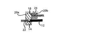
本発明に係るロゴスキーループ電流変換器2は、変換器が一次導体の周囲において動作する時に、コイルの二つの端部14、16を接続するように構成された閉機構18を更に含む。閉機構は、コイルの両端部14、16を接続しており、強磁性体材料からなる一つ又は二つの部分によるボディ20、20a、20bにより構成される磁気回路を備える。強磁性体材料とは、空気の透磁性(透磁率)に比して高透磁性を有する材料を指す。説明する実施形態において、ボディは、空洞又はハウジング22、24又はハウジングの部分を含み、これらは、強磁性体材料が両端部14、16を囲むように、両端部14、16を収容する。強磁性体材料は、例えばフェライト、又は鉄シリコン合金もしくは鉄ニッケル合金、又は非晶質もしくはナノ結晶の材料、又は磁性体材料を添加されたプラスチック等であればよい。ボディ20、20a、20bは、有利には、フェライト、又は強磁性体材料の粒子等の強磁性体材料を含有する熱可塑性物質によって、一つ又は二つの部分に成形されたものであればよい。また、強磁性体材料のボディを、組立又はオーバーモールドにより、プラスチック等の他の材料のボディ又は箱体に内蔵することもできる。
The Rogowski loop
戻り点を有する端部16は、取り外し可能に又は非恒常的に、ハウジング内に挿入したり、又は位置づけたりすることができる。接続装置又はケーブル12に接続された端部14は、好ましくは、恒常的な取付手段(接着、圧着、オーバーモールド等)によって閉機構に取り付けられるように、対応するボディの空洞又は空洞部内に収容される。結果として、コイルの接続端部14、接続装置、及び閉機構を、強固に接続することができる。しかしながら、コイルの端部14は、分解及び取付機構からの分離を行うために、接続装置又はケーブルに非恒常的に(図示しない機械的な取付用クリップ等により)接続することもできる。
The
コイル及びケーブルの間の接続線の周囲の部分は、磁界に対して感受性を有し、生成された信号に誤差を生じさせるおそれがあるため、強磁性体材料のボディは、この接続線の周囲のシールドの役割を果たすという利点も有する。 The portion of the connection wire between the coil and the cable is sensitive to the magnetic field and can cause errors in the generated signal. It also has the advantage of serving as a shield.
寄生信号がコイル/ケーブルの接合面及びケーブル自体に誘導され得るのを更に減少させるために、磁気シールドされた接続ケーブルを使用することができる。この接続ケーブルは、強磁性体内に入り、前記シールドを確実に継続させる。特に、熱可塑性のシースに強磁性体材料が添加されたケーブルを使用することができる。 In order to further reduce the parasitic signals that can be induced on the coil / cable interface and the cable itself, a magnetically shielded connection cable can be used. This connecting cable enters the ferromagnetic body and ensures that the shield continues. In particular, a cable in which a ferromagnetic material is added to a thermoplastic sheath can be used.
閉機構のボディは、図2b及び3cに示されるように、単一の部分20から、又は図2c及び3d〜3fに示されるように、二つの部分20a、20bから、又は変換器が一次導体の周囲に組み立てられる場合に結合が可能な三つ以上の部分から、形成することができる。ボディの部分を組み立てて閉じるために、異なる取付手段又は固定手段(ねじ、クリップ等)を使用することができる。
The body of the closing mechanism may be from a
図2a、2bに説明する実施形態においては、コイルの両端部を収容する空洞又は空洞部22、24は一線に並んでおり、これに対して、図3a〜3cに説明する実施形態においては、空洞又は空洞部22、24は重なっている。これら二つの実施形態において、コイルの自由端16は、一次導体の周囲のループを閉じるために、対応する空洞に単純に挿入することができる。コイルの自由端16は、摩擦又は取付手段によって空洞内に保持することができる。
In the embodiment illustrated in FIGS. 2a and 2b, the cavities or
本発明の範囲内において、ボディのハウジング内に端部16を挿入する代わりに、図2c及び3d〜3fに示すように、コイルの各端部を、一次導体の周囲にコイルを組み立てて閉じるために結合させることのできる、分離可能なボディ20a、20bのそれぞれの部分に恒常的に取り付けることができる。
Within the scope of the present invention, instead of inserting the
閉機構18は、外部機器の接続プラグへ変換器を接続するための(ケーブルに代わる)接続端子や、測定信号処理回路(図示せず)等の、他の構成部品と共に強磁性体材料のボディ又はボディ部分を搭載した箱体(図示せず)を更に含むことができる。
The
本発明の範囲内において、コイルの両端部を磁気回路によって接続するために、コイルの端部が貫通する強磁性体の空洞を、コイルのこの端部を貫通するボディの突出部に置き換えることができる。 Within the scope of the present invention, in order to connect both ends of the coil by a magnetic circuit, the ferromagnetic cavity through which the end of the coil penetrates may be replaced by a body protrusion that penetrates this end of the coil. it can.
強磁性体材料のボディによって、ロゴスキーループを非常に容易に閉じることができると同時に、ループの不完全な閉じとその結果であるアンペールの法則における経路の不連続とに起因する、測定の不正確さを制限することができる。コイルの両端部を包囲する又はコイルの両端部が挿入された磁気回路の一部分を挿入することによって、アンペールの法則における経路の不連続を減少させ、更には解消もする。空気の透磁性に対して、例えば50倍から1000倍の透磁性を有する磁性体材料は、二つの端部が一致することに相当する磁気短絡を発生させる。その結果、磁気の観点からは、アンペールの法則における経路が完成し、不連続が原則的になくなる。これにより、ループ外部の磁界に対する感受性、及びループ内部の測定対象の一次導体の位置決めに対する感受性がなくなるという効果が顕著に高まることになる。 The body of ferromagnetic material allows the Rogowski loop to be closed very easily, while at the same time measuring inaccuracy due to incomplete closure of the loop and the resulting path discontinuity in Ampere's law Can be limited. By inserting a portion of the magnetic circuit that encloses the ends of the coil or inserts both ends of the coil, path discontinuities in Ampere's law are reduced and even eliminated. For example, a magnetic material having a permeability of 50 to 1000 times the permeability of air generates a magnetic short circuit corresponding to the coincidence of the two ends. As a result, from a magnetic point of view, the path in Ampere's law is completed and discontinuities are essentially eliminated. Thereby, the effect that the sensitivity to the magnetic field outside the loop and the sensitivity to the positioning of the primary conductor to be measured inside the loop is lost is remarkably enhanced.
本発明に係る変換器の利点を挙げる。
・一次導体の周囲のコイルを、容易かつ確実に再び閉じることができる。磁気回路を自由端が一旦貫通すると、経路が完成し精度が最適となる。
・自由端を取り付けるために、複雑又は精密な構造を必要としない。
・低コストで適切な形状(成形による形状)のフェライト材料の使用が可能である。
・両端部の重なりが、外部の磁界に対する感受性又は一次導体の位置決めに対する感受性に影響しない。
The advantages of the converter according to the invention are listed.
-The coil around the primary conductor can be easily and reliably closed again. Once the free end penetrates the magnetic circuit, the path is complete and the accuracy is optimal.
-No complicated or precise structure is required to attach the free end.
-It is possible to use ferrite material of appropriate shape (shape by molding) at low cost.
-Overlap of both ends does not affect sensitivity to external magnetic field or primary conductor positioning.
Claims (14)
二つの端部(14、16)の間に延在し、前記両端部を分離し元の位置に戻すことで測定対象の電流が流れる一次導体の周囲に設置可能となるように構成されたコイル(4)と、前記コイルの前記両端部を接続するように構成され、当該ループが閉じられる場合に前記両端部の間に延在する磁気回路を有する閉機構(18)とを備えるロゴスキーループ電流変換器。 Rogowski loop current converter,
A coil that extends between two ends (14, 16) and is configured to be installed around a primary conductor through which a current to be measured flows by separating the both ends and returning them to their original positions. Rogowski loop current comprising (4) and a closing mechanism (18) configured to connect the ends of the coil and having a magnetic circuit extending between the ends when the loop is closed converter.
Applications Claiming Priority (3)
| Application Number | Priority Date | Filing Date | Title |
|---|---|---|---|
| EP07405183A EP2009453B1 (en) | 2007-06-28 | 2007-06-28 | Rogowski current sensor |
| EP07405183.0 | 2007-06-28 | ||
| PCT/IB2008/001581 WO2009001185A1 (en) | 2007-06-28 | 2008-06-18 | Rogowski current sensor |
Publications (3)
| Publication Number | Publication Date |
|---|---|
| JP2010531452A JP2010531452A (en) | 2010-09-24 |
| JP2010531452A5 JP2010531452A5 (en) | 2011-05-19 |
| JP5397961B2 true JP5397961B2 (en) | 2014-01-22 |
Family
ID=38754573
Family Applications (1)
| Application Number | Title | Priority Date | Filing Date |
|---|---|---|---|
| JP2010514163A Active JP5397961B2 (en) | 2007-06-28 | 2008-06-18 | Rogowski current converter |
Country Status (7)
| Country | Link |
|---|---|
| US (1) | US8324883B2 (en) |
| EP (1) | EP2009453B1 (en) |
| JP (1) | JP5397961B2 (en) |
| CN (1) | CN101688887B (en) |
| AT (1) | ATE507479T1 (en) |
| DE (1) | DE602007014195D1 (en) |
| WO (1) | WO2009001185A1 (en) |
Families Citing this family (24)
| Publication number | Priority date | Publication date | Assignee | Title |
|---|---|---|---|---|
| FR2943792B1 (en) | 2009-03-30 | 2011-05-06 | Areva T & D Sa | CURRENT SENSOR IN THE FORM OF A CABLE TO ATTACH IN LOOP |
| JP2010256141A (en) * | 2009-04-23 | 2010-11-11 | Toshiba Toko Meter Systems Co Ltd | Current detection apparatus and watt-hour meter using the same |
| JP5646203B2 (en) * | 2010-04-26 | 2014-12-24 | 日置電機株式会社 | Current sensor |
| JP5646217B2 (en) * | 2010-06-01 | 2014-12-24 | 日置電機株式会社 | Current sensor |
| DE102010039820A1 (en) * | 2010-08-26 | 2012-03-01 | Siemens Aktiengesellschaft | Circuit breaker with Rogowski current transformers for measuring the current in the circuit breaker conductors |
| EP2625699B1 (en) | 2010-10-04 | 2015-12-16 | ABB Technology AG | Multifunctional measuring device |
| US9291647B2 (en) * | 2012-03-28 | 2016-03-22 | Analog Devices, Inc. | Low-cost Rogowski coil sensors |
| EP2759842A1 (en) | 2013-01-29 | 2014-07-30 | Itron France | Method and apparatus for current correction |
| US20140269214A1 (en) * | 2013-03-15 | 2014-09-18 | Elwha LLC, a limited liability company of the State of Delaware | Portable electronic device directed audio targeted multi-user system and method |
| FR3015687B1 (en) | 2013-12-23 | 2016-01-22 | Schneider Electric Ind Sas | ROGOWSKI LOOP CURRENT SENSOR AND METHOD FOR MANUFACTURING SUCH CURRENT SENSOR |
| US9408298B2 (en) | 2014-03-18 | 2016-08-02 | Eaton Corporation | Flexible circuit Rogowski coil |
| US10670633B2 (en) * | 2015-09-02 | 2020-06-02 | Veris Industries, Llc | Rogowski coil based alarm system |
| ES1160858Y (en) * | 2016-06-20 | 2016-10-04 | Smilics Tech S L | FLEXIBLE TYPE CURRENT SENSOR |
| FR3068137B1 (en) * | 2017-06-23 | 2019-08-23 | Neelogy | CIRCULATING MAGNETIC FIELD SENSOR |
| US10746767B2 (en) * | 2018-05-09 | 2020-08-18 | Fluke Corporation | Adjustable length Rogowski coil measurement device with non-contact voltage measurement |
| JP7058548B2 (en) * | 2018-05-09 | 2022-04-22 | 日置電機株式会社 | Current sensor and measuring device |
| JP7206803B2 (en) * | 2018-10-26 | 2023-01-18 | スミダコーポレーション株式会社 | Coil wire, current sensor material and current sensor |
| JP7311261B2 (en) * | 2018-11-09 | 2023-07-19 | 日置電機株式会社 | Flexible sensor and measuring device |
| DE102019102567B3 (en) * | 2019-02-01 | 2020-03-05 | Dr. Ing. H.C. F. Porsche Aktiengesellschaft | Sensor device for measuring direct and alternating currents |
| DE102019115339B4 (en) * | 2019-06-06 | 2024-03-28 | Dr. Ing. H.C. F. Porsche Aktiengesellschaft | Sensor device for measuring alternating currents with an improved locking mechanism |
| EP3783370A1 (en) | 2019-08-20 | 2021-02-24 | LEM International SA | Rogowski current transducer |
| US11736026B2 (en) * | 2020-05-29 | 2023-08-22 | Dialog Semiconductor Inc. | Flyback converter with fast load transient detection |
| WO2022202367A1 (en) * | 2021-03-24 | 2022-09-29 | 国立大学法人九州工業大学 | Rogowski type current sensor, inverter, and method for installing rogowski type current sensor |
| FR3132953A1 (en) | 2022-02-24 | 2023-08-25 | Omegawatt | Magnetic closure system for Rogowski buckle |
Family Cites Families (11)
| Publication number | Priority date | Publication date | Assignee | Title |
|---|---|---|---|---|
| FR1478330A (en) * | 1965-04-23 | 1967-04-28 | Telemecanique Electrique | Improvement in the measurement of industrial currents up to high frequencies |
| FR2583171B1 (en) * | 1985-06-07 | 1988-06-17 | Commissariat Energie Atomique | FREQUENCY BROADBAND MAGNETIC FIELD DETECTOR |
| JPH048376Y2 (en) * | 1987-11-09 | 1992-03-03 | ||
| JPH0831665A (en) * | 1994-07-14 | 1996-02-02 | Taiyo Yuden Co Ltd | Magnetically shielded chip inductor |
| DE29706641U1 (en) * | 1997-04-14 | 1997-05-28 | Karl Pfisterer Elektrotechnische Spezialartikel Gmbh & Co Kg, 70327 Stuttgart | Connector system |
| DE69915816T2 (en) | 1998-04-22 | 2005-03-17 | Power Electronic Measurements Ltd. | Current measuring device |
| US6313623B1 (en) | 2000-02-03 | 2001-11-06 | Mcgraw-Edison Company | High precision rogowski coil |
| JP2002181850A (en) * | 2000-12-12 | 2002-06-26 | Denki Kogyo Co Ltd | Current detector |
| JP4550311B2 (en) * | 2001-05-08 | 2010-09-22 | 日置電機株式会社 | Flexible sensor |
| JP3971158B2 (en) * | 2001-11-07 | 2007-09-05 | 日置電機株式会社 | Current sensor |
| JP4410150B2 (en) * | 2005-05-26 | 2010-02-03 | 三菱電機株式会社 | Current detector |
-
2007
- 2007-06-28 AT AT07405183T patent/ATE507479T1/en not_active IP Right Cessation
- 2007-06-28 DE DE602007014195T patent/DE602007014195D1/en active Active
- 2007-06-28 EP EP07405183A patent/EP2009453B1/en active Active
-
2008
- 2008-06-18 WO PCT/IB2008/001581 patent/WO2009001185A1/en active Application Filing
- 2008-06-18 US US12/666,903 patent/US8324883B2/en active Active
- 2008-06-18 CN CN2008800224772A patent/CN101688887B/en active Active
- 2008-06-18 JP JP2010514163A patent/JP5397961B2/en active Active
Also Published As
| Publication number | Publication date |
|---|---|
| CN101688887A (en) | 2010-03-31 |
| US8324883B2 (en) | 2012-12-04 |
| EP2009453B1 (en) | 2011-04-27 |
| EP2009453A1 (en) | 2008-12-31 |
| JP2010531452A (en) | 2010-09-24 |
| WO2009001185A1 (en) | 2008-12-31 |
| CN101688887B (en) | 2012-12-26 |
| ATE507479T1 (en) | 2011-05-15 |
| DE602007014195D1 (en) | 2011-06-09 |
| WO2009001185A8 (en) | 2010-01-21 |
| US20120126789A1 (en) | 2012-05-24 |
Similar Documents
| Publication | Publication Date | Title |
|---|---|---|
| JP5397961B2 (en) | Rogowski current converter | |
| JP7090928B2 (en) | Magnetically shielded current transformer | |
| KR100965818B1 (en) | Clamp-type current sensor with a rogowski coil | |
| US20100001715A1 (en) | Folding current sensor | |
| AU2012216505B2 (en) | Sensor devices and methods for use in sensing current through a conductor | |
| JP6661541B2 (en) | Current transducer or current transformer clipping | |
| CA2898935C (en) | Sensor devices and methods for use in sensing current through a conductor | |
| JP2013061327A (en) | Sensor devices and methods for use in sensing current through conductor | |
| GB2422675A (en) | Flow meter with detachable coils | |
| WO2016098750A1 (en) | Current sensor and measurement device | |
| JP2016033512A (en) | Sensor devices and methods for use in sensing current through conductor | |
| JP2006046922A (en) | Current sensor | |
| CN107103982B (en) | Magnetic core for sensor | |
| CN105799951B (en) | The micro- magnetic torquer of electromechanical integration and magnetic moment measurement method | |
| US9297829B2 (en) | Multifunctional measuring device | |
| JP2007285767A (en) | Current detection mechanism and its attachment means | |
| JP2006343157A (en) | Current sensor | |
| JP2003121476A (en) | Electric current sensor | |
| CN216622491U (en) | Small single three-phase current sensor | |
| JP4551629B2 (en) | Current sensor | |
| CN110865222A (en) | Current sensor | |
| JP3886423B2 (en) | Magnetic field detector | |
| JP2018054588A (en) | Current sensor | |
| JP2012255685A (en) | Current sensor | |
| JP2007304013A (en) | Detecting part for position sensor, and position sensor |
Legal Events
| Date | Code | Title | Description |
|---|---|---|---|
| A521 | Request for written amendment filed |
Free format text: JAPANESE INTERMEDIATE CODE: A523 Effective date: 20110331 |
|
| A621 | Written request for application examination |
Free format text: JAPANESE INTERMEDIATE CODE: A621 Effective date: 20110331 |
|
| A131 | Notification of reasons for refusal |
Free format text: JAPANESE INTERMEDIATE CODE: A131 Effective date: 20130205 |
|
| A521 | Request for written amendment filed |
Free format text: JAPANESE INTERMEDIATE CODE: A523 Effective date: 20130423 |
|
| TRDD | Decision of grant or rejection written | ||
| A01 | Written decision to grant a patent or to grant a registration (utility model) |
Free format text: JAPANESE INTERMEDIATE CODE: A01 Effective date: 20130924 |
|
| A61 | First payment of annual fees (during grant procedure) |
Free format text: JAPANESE INTERMEDIATE CODE: A61 Effective date: 20131017 |
|
| R150 | Certificate of patent or registration of utility model |
Ref document number: 5397961 Country of ref document: JP Free format text: JAPANESE INTERMEDIATE CODE: R150 Free format text: JAPANESE INTERMEDIATE CODE: R150 |
|
| R250 | Receipt of annual fees |
Free format text: JAPANESE INTERMEDIATE CODE: R250 |
|
| R250 | Receipt of annual fees |
Free format text: JAPANESE INTERMEDIATE CODE: R250 |
|
| R250 | Receipt of annual fees |
Free format text: JAPANESE INTERMEDIATE CODE: R250 |
|
| R250 | Receipt of annual fees |
Free format text: JAPANESE INTERMEDIATE CODE: R250 |
|
| S111 | Request for change of ownership or part of ownership |
Free format text: JAPANESE INTERMEDIATE CODE: R313113 |
|
| S531 | Written request for registration of change of domicile |
Free format text: JAPANESE INTERMEDIATE CODE: R313531 |
|
| R250 | Receipt of annual fees |
Free format text: JAPANESE INTERMEDIATE CODE: R250 |
|
| R350 | Written notification of registration of transfer |
Free format text: JAPANESE INTERMEDIATE CODE: R350 |
|
| R250 | Receipt of annual fees |
Free format text: JAPANESE INTERMEDIATE CODE: R250 |
|
| R250 | Receipt of annual fees |
Free format text: JAPANESE INTERMEDIATE CODE: R250 |
|
| R250 | Receipt of annual fees |
Free format text: JAPANESE INTERMEDIATE CODE: R250 |