JP5388772B2 - Image forming apparatus - Google Patents
Image forming apparatus Download PDFInfo
- Publication number
- JP5388772B2 JP5388772B2 JP2009216168A JP2009216168A JP5388772B2 JP 5388772 B2 JP5388772 B2 JP 5388772B2 JP 2009216168 A JP2009216168 A JP 2009216168A JP 2009216168 A JP2009216168 A JP 2009216168A JP 5388772 B2 JP5388772 B2 JP 5388772B2
- Authority
- JP
- Japan
- Prior art keywords
- recording medium
- calibration
- arbitrary
- image
- image forming
- Prior art date
- Legal status (The legal status is an assumption and is not a legal conclusion. Google has not performed a legal analysis and makes no representation as to the accuracy of the status listed.)
- Expired - Fee Related
Links
Images


Classifications
-
- H—ELECTRICITY
- H04—ELECTRIC COMMUNICATION TECHNIQUE
- H04N—PICTORIAL COMMUNICATION, e.g. TELEVISION
- H04N1/00—Scanning, transmission or reproduction of documents or the like, e.g. facsimile transmission; Details thereof
- H04N1/46—Colour picture communication systems
- H04N1/56—Processing of colour picture signals
- H04N1/60—Colour correction or control
- H04N1/603—Colour correction or control controlled by characteristics of the picture signal generator or the picture reproducer
- H04N1/6033—Colour correction or control controlled by characteristics of the picture signal generator or the picture reproducer using test pattern analysis
-
- H—ELECTRICITY
- H04—ELECTRIC COMMUNICATION TECHNIQUE
- H04N—PICTORIAL COMMUNICATION, e.g. TELEVISION
- H04N1/00—Scanning, transmission or reproduction of documents or the like, e.g. facsimile transmission; Details thereof
- H04N1/46—Colour picture communication systems
- H04N1/56—Processing of colour picture signals
- H04N1/60—Colour correction or control
- H04N1/6097—Colour correction or control depending on the characteristics of the output medium, e.g. glossy paper, matt paper, transparency or fabrics
Description
本発明は、画像の品質を維持するためのキャリブレーションに関する。 The present invention relates to calibration for maintaining image quality.
画像形成装置の画像品質は、画像形成装置が使用される環境や画像形成装置の使用状況によって変動する。また、画像品質は、使用される記録媒体の種類によっても変動する。よって、環境や使用状況に依存して画像変換条件や画像形成条件を変更する必要がある(特許文献1)。同様に、使用される記録媒体の種類に応じて画像変換条件や画像形成条件を追加する必要もある(特許文献2)。 The image quality of the image forming apparatus varies depending on the environment in which the image forming apparatus is used and the usage status of the image forming apparatus. Also, the image quality varies depending on the type of recording medium used. Therefore, it is necessary to change the image conversion conditions and the image forming conditions depending on the environment and usage conditions (Patent Document 1). Similarly, it is necessary to add image conversion conditions and image forming conditions according to the type of recording medium used (Patent Document 2).
特許文献1では、特定の記録媒体が、毎回、キャリブレーションに使用されることが前提とされている。よって、特定の記録媒体がなくなってしまうと、キャリブレーションを実行できなくなってしまう。特許文献2の発明でも、追加された任意の記録媒体についてキャリブレーションを行うには、やはりこれと同一の種類の記録媒体を、毎回、用意しなければならない。ちなみに、異なる種類の記録媒体を用いてキャリブレーションを実行してしまうと、たとえば、トナーの載り量が十分でなくなってしまったり、画像形成装置の設計で定められた許容範囲を載り量が超えてしまったりする。これは、画像品質を維持できなくなることを意味する。仮に、所望の記録媒体についてのキャリブレーションを他の種類の記録媒体を用いて実行できれば、操作者にとって便利であろう。
In
ところで、複数の任意の記録媒体をキャリブレーションで使用できるように登録した場合、複数の任意の記録媒体間でキャリブレーション精度が異なってしまうことがある。これは、演算誤差等が原因である。とりわけ、予めメーカーによって指定された特定の記録媒体に対して特性の大きく異なる記録媒体をキャリブレーション用に登録すると、キャリブレーション精度が低下しやすい。 By the way, when a plurality of arbitrary recording media are registered so that they can be used for calibration, the calibration accuracy may be different among the plurality of arbitrary recording media. This is due to a calculation error or the like. In particular, if a recording medium having greatly different characteristics with respect to a specific recording medium designated in advance by a manufacturer is registered for calibration, the calibration accuracy is likely to decrease.
そこで、本発明は、このような課題および他の課題のうち、少なくとも1つを解決することを目的とする。たとえば、本発明は、複数の任意の記録媒体がキャリブレーション用に登録されている場合にキャリブレーション精度の高い記録媒体を優先的に使用できるようにすることを目的とする。なお、他の課題については明細書の全体を通して理解できよう。 Therefore, an object of the present invention is to solve at least one of such problems and other problems. For example, an object of the present invention is to preferentially use a recording medium with high calibration accuracy when a plurality of arbitrary recording media are registered for calibration. Other issues can be understood throughout the specification.
本発明は、たとえば、記録媒体上に形成された測定用画像から得られた輝度値を変換設定情報に基づいて変換し、当該変換結果に基づいてキャリブレーションを実行するキャリブレーション実行手段と、
前記キャリブレーションに使用可能な記録媒体として予め特定された記録媒体とは異なる任意の記録媒体を追加するために、追加する記録媒体に対応する前記変換設定情報を作成する追加手段と、
前記追加手段により追加された複数の任意の記録媒体におけるそれぞれの特性を示す特性情報を記憶する記憶手段と、
前記複数の任意の記録媒体におけるそれぞれの特性情報を前記予め特定された記録媒体の特性と比較することで、前記予め特定された記録媒体の特性に対して相対的に近似している任意の記録媒体を決定する決定手段と、を有し、
前記キャリブレーション実行手段は、前記決定手段により決定された記録媒体と、当該記録媒体に対応する前記追加手段により作成された前記変換設定情報とを使用して前記キャリブレーションを実行することを特徴とする画像形成装置を提供する。
The present invention includes, for example, a calibration execution unit that converts a luminance value obtained from a measurement image formed on a recording medium based on conversion setting information, and executes calibration based on the conversion result;
Adding means for creating the conversion setting information corresponding to the recording medium to be added in order to add an arbitrary recording medium different from the recording medium specified in advance as the recording medium usable for the calibration;
Storage means for storing characteristic information indicating respective characteristics of a plurality of arbitrary recording media added by the adding means;
Arbitrary recording that is relatively approximate to the characteristics of the previously specified recording medium by comparing the characteristic information of each of the plurality of arbitrary recording media with the characteristics of the previously specified recording medium Determining means for determining a medium;
The calibration execution means executes the calibration using the recording medium determined by the determination means and the conversion setting information created by the additional means corresponding to the recording medium. An image forming apparatus is provided .
本発明によれば、複数の任意の記録媒体がキャリブレーション用に登録されている場合にキャリブレーション精度の高い記録媒体を優先的に使用できるようになる。 According to the present invention, when a plurality of arbitrary recording media are registered for calibration, a recording medium with high calibration accuracy can be preferentially used.
以下に本発明の一実施形態を示す。以下で説明される個別の実施形態は、本発明の上位概念、中位概念および下位概念など種々の概念を理解するために役立つであろう。また、本発明の技術的範囲は、特許請求の範囲によって確定されるのであって、以下の個別の実施形態によって限定されるわけではない。 An embodiment of the present invention is shown below. The individual embodiments described below will help to understand various concepts, such as the superordinate concept, intermediate concept and subordinate concept of the present invention. Further, the technical scope of the present invention is determined by the scope of the claims, and is not limited by the following individual embodiments.
[実施例1]
以下では、電子写真方式のカラー複写機に適用する実施例について説明する。なお、本発明は、キャリブレーションが必要となる画像形成装置であれば適用できる。すなわち、画像形成方式は、電子写真方式に制限されることはなく、インクジェット方式、静電記録方式、その他の方式であってもよい。また、本発明は、多色画像を形成する画像形成装置だけでなく、単色画像を形成する画像形成装置にも適用できる。画像形成装置は、たとえば、印刷装置、プリンタ、複写機、複合機、ファクシミリとして製品化されてもよい。また、記録媒体は、記録紙、記録材、用紙、シート、転写材、転写紙と呼ばれることもある。さらに、記録媒体の素材は、紙、繊維、フィルム又は樹脂などであってもよい。
[Example 1]
An embodiment applied to an electrophotographic color copier will be described below. The present invention is applicable to any image forming apparatus that requires calibration. In other words, the image forming method is not limited to the electrophotographic method, and may be an ink jet method, an electrostatic recording method, or other methods. Further, the present invention can be applied not only to an image forming apparatus that forms a multicolor image but also to an image forming apparatus that forms a single color image. The image forming apparatus may be commercialized as, for example, a printing apparatus, a printer, a copier, a multifunction machine, or a facsimile. The recording medium may also be called recording paper, recording material, paper, sheet, transfer material, or transfer paper. Further, the material of the recording medium may be paper, fiber, film or resin.
<基本的なハードウエア構成>
図1が示す複写機100は、原稿から画像を読み取るリーダ部Aと、リーダ部Aにより得られた画像を記録媒体上に形成するプリンタ部Bとによって構成されている。リーダ部Aは、原稿台ガラス102上に載置された原稿101を読み取る前に基準白色板106を読み取り、いわゆるシェーディング補正を実行する。原稿101は、光源103によって光を照射され、その反射光は光学系104を介してCCDセンサー105に結像する。CCDセンサー105等の読取ユニットは矢印K1の方向に移動することにより、原稿をラインごとの電気信号データ列に変換する。なお、読取ユニットが移動する代わりに原稿が移動してもよい。電気信号データ列は、リーダ画像処理部108によって画像信号に変換される。
<Basic hardware configuration>
A
図2が示すCCDセンサー105により得られた画像信号は、CCD/AP回路基盤201のアナログ画像処理部202でゲイン等を調整され、A/D変換部203でデジタルの画像信号に変換され、リーダ部Aコントローラ回路基盤210に出力される。リーダ部Aコントローラ回路基盤210のシェーディング処理部212をCPU211により制御されながら画像信号をシェーディング補正してプリンタ部Bのプリンタ制御部109へ出力する。この時点で、画像信号は、RGBの各輝度情報により構成されている。
The image signal obtained by the
次にプリンタ部Bの説明を行う。図1によれば、プリンタ制御部109により画像信号はPWM(パルス幅変調)されたレーザービームに変換される。レーザービームは、ポリゴンスキャナ110で偏向走査され、画像形成部120、130、140、150の各感光ドラム121、131、141、151を露光する。これにより、静電潜像が形成される。画像形成部120、130、140、150は、イエロー色(Y)、マゼンタ色(M)、シアン色(C)、ブラック色(Bk)に対応している。画像形成部120、130、140、150の構成は略同一なので、イエローを担当する画像形成部120についてのみ説明する。1次帯電器122は、感光ドラム121の表面を所定の電位に帯電させる。現像器123は、感光ドラム121上の静電潜像を現像してトナー画像を形成する。転写ブレード124は、転写ベルト111の背面から放電を行い、感光ドラム121上のトナー画像を転写ベルト111上の記録媒体へ転写する。その後、記録媒体は、定着器114でトナー画像を定着される。
Next, the printer unit B will be described. According to FIG. 1, the
なお、各感光ドラム121、131、141、151には、その表面電位を計測するための表面電位計125、135、145、155が設けられている。表面電位計125、135、145、155は、コントラスト電位を調整するために使用される。
Each
図3が示すプリンタ制御部109の各部は、CPU301によって統括的に制御される。メモリ302は、ROMやRAMであり、制御プログラムや各種のデータが格納される。リーダAまたはプリントサーバC等で処理された画像信号は、プリンタ制御部109の色処理部303に入力される。色処理部303は、プリンタの出力特性が理想的であった場合に所望の出力が得られるよう、入力された画像信号に画像処理及び色処理を適用する。入力信号の階調数は8bitであるが、精度向上のため色処理部303で10bitに拡張される。その後、画像信号はディザ処理部307でディザ処理されて4bitの信号に変換される。LUTid304は、リーダAからの画像信号に含まれている輝度情報を濃度情報に変換する輝度−濃度変換テーブルである。LUTid304は、当初は特定の記録媒体について用意されているが、本実施例では任意の記録媒体の追加作業を実行することによって、任意の記録媒体用のLUTid304が追加される。
Each unit of the
階調制御部311は、LUTb312、UCR部305と、LUTa306とを備え、プリンタ部Bを理想的な特性に合わせるべく画像信号を補正する。LUTa306、LUTb312は、濃度特性を補正するための10bitの変換テーブルであり、とりわけ、プリンタ部Bのγ特性を変更するために使用される。LUTa306は、プリンタ部Bの特性を適正にするために特定の記録媒体Xに対して作成される。なお、特定の記録媒体Xは、画像形成装置のメーカーによって階調性が所望の階調性となるようにあらかじめ設計された記録媒体である。本発明のLUTa306は他の記録媒体に対しても共通して使用されるものとする。よって、LUTa306は、任意の記録媒体を用いたときのプリンタ部Bの特性を、特定の記録媒体を用いたときのプリンタ部Bの特性に同一または近づける役割を果たす。LUTb312は、記録媒体ごとの階調特性を適切に調整するために使用される。よって、LUTb312は、記録媒体ごとに用意される。UCR部305は、各画素における画像信号の積算値を規制することで、画像信号レベルの総和を制限する回路である。総和が規定値を超えた場合、UCR部305は、所定量のCMY信号をK信号に置き換える下色除去処理(UCR)を実行し、画像信号レベルの総和を低下させる。ここで画像信号レベルの総和を規制するのは、プリンタ部Bでの画像形成におけるトナー載り量を規制するためである。本実施例で行うプリンタ部Bの動作の適正化とは、トナー載り量が規定値を超えることにより発生する画像不良等を防ぐことである。本実施例では、UCR部305の前段に配置されたLUTb312によって階調特性を調整するため、階調特性を任意の記録媒体向けに最適化したとしてもトナー載り量が規定値を超えることはない。
The
階調制御部311から出力された信号は、ディザ処理部307でディザ処理され、PWM部308でパルス幅変調される。レーザードライバ309は、PWM変調された信号を使用して半導体レーザを発光させる。このため、ディザ処理部307は10bitの画像信号を4bitデータに変換するための中間調処理を行う。
The signal output from the
<画像形成条件の制御>
本発明の特徴はユーザー任意の記録媒体におけるキャリブレーションでプリンタ特性を適正にすることにある。まずは、予め設定されている特定の記録媒体Xを用いた場合のキャリブレーションについて説明する。記録媒体Xは、例えば、画像形成装置のメーカーによって工場出荷時に指定された記録媒体またはメンテナンス担当者によってメンテナンス時に指定された記録媒体などである。本実施例においてはコントラスト電位を制御する第1のキャリブレーション機能と、画像データのγ補正回路(LUTa306)を制御する第2のキャリブレーション機能とが存在する。
<Control of image forming conditions>
A feature of the present invention resides in that printer characteristics are made appropriate by calibration on a recording medium arbitrarily selected by the user. First, calibration when a specific recording medium X that is set in advance is used will be described. The recording medium X is, for example, a recording medium designated at the time of factory shipment by the manufacturer of the image forming apparatus or a recording medium designated at the time of maintenance by a maintenance person. In the present embodiment, there is a first calibration function for controlling the contrast potential and a second calibration function for controlling the γ correction circuit (LUTa 306) for image data.
I.第1のキャリブレーション
図4において、CPU301が、特定の記録媒体に形成された画像から得られた第1輝度情報を使用してコントラスト電位を決定するための第1キャリブレーションを実行する第1キャリブレーション手段として機能する。
I. First Calibration In FIG. 4, the
S401で、CPU301は、第1のテストプリントの出力と、感光ドラムの表面電位の測定を実行する。たとえば、CPU301は、第1のテストパターンを作成して色処理部303へ出力することで、特定の記録媒体Xに第1のテストパターンが画像として形成される。これが第1のテストプリントとなる。なお、第1のテストプリントを出力する際に使用されるコントラスト電位は、そのときの雰囲気環境(例:絶対水分量)において目標濃度を達成すると予測された初期値が設定される。メモリ302には、様々な雰囲気環境のそれぞれに対応したコントラスト電位の値が記憶されているものとする。CPU301は、絶対水分量を測定し、測定した絶対水分量に対応したコントラスト電位を決定する。第1のテストパターンは、たとえば、Y、M、C、Bkの中間階調濃度からなる帯パターンと、Y、M、C、Bkごとの最大濃度パッチ(例:255レベルの濃度信号)からなるパッチパターンとを含む。表面電位計125、135、145、155は、各最大濃度パッチを形成したときの実際のコントラスト電位を測定する。
In step S401, the
S402で、リーダAは、出力された第1のテストプリントを読み取り、RGB値をプリンタ制御部109のCPU301に渡す。CPU301は、特定の記録媒体Xについて予め用意されているLUTid(X)を用いてRGB値を光学濃度に換算する。LUTid(X)は、特定の記録媒体Xにおける濃度情報とリーダAでの読み取り輝度値との関係より設定した変換テーブルである。後述する、任意の記録媒体Zをキャリブレーションで使用可能にするためのLUTid(Z)はこのLUTid(X)を変更することで作成される。
In step S <b> 402, the reader A reads the output first test print and passes the RGB values to the
S403で、CPU301は、目標最大濃度に対応するコントラスト電位bを算出する。図5の横軸は現像バイアス電位を示し、縦軸は画像濃度を示している。コントラスト電位は、現像バイアス電位と、感光ドラムが一次帯電された後に各色の半導体レーザ310が最大レベルで発光したときの感光ドラムの表面電位との差である。コントラスト電位aを使用して形成された第1のテストプリントから得られた最大濃度がDaであったとする。この場合、最大濃度付近(濃度0.8〜2.0)では、コントラスト電位に対して画像濃度が実線Lに示すように線形となる。実線Lは、コントラスト電位aと、最大濃度Daとによって確定される。本実施例においては一例として目標最大濃度を1.6とする。CPU301は、目標最大濃度に対応するコントラスト電位bを実線Lに基づいて算出する。実線Lに相当するテーブルまたは関数が予めメモリ302に格納されているものとする。コントラスト電位bは、例えば、次式(1)を用いて算出される。
In S403, the
b=(a+ka)×1.6/Da ・・・(1)
ここで、kaは補正係数であり、現像方式の種類によって決定される値である。
b = (a + ka) × 1.6 / Da (1)
Here, ka is a correction coefficient, which is a value determined by the type of development method.
S404で、CPU301は、コントラスト電位bからグリッド電位Vgと現像バイアス電位Vdsを決定して設定する。
In S404, the
図6によれば、CPU301は、グリッド電位Vgを−300Vに設定し、各色の半導体レーザ310の発光パルスレベルを最小にして走査を実行させ、表面電位計125、135、145、155で表面電位Vdを測定する。さらに、CPU301は、グリッド電位Vgを−300Vに設定し、各色の半導体レーザ310の発光パルスレベルを最大にしたときの表面電位Vlを表面電位計125、135、145、155で測定する。同様にCPU301はグリッド電位Vgを−700Vに設定したときの表面電位Vd、Vlを測定する。−300Vのデータと−700Vのデータとを補間または外挿することで、CPU301は、図6に示したグリッド電位と感光ドラム表面電位の関係は求めることができる。この電位データを求めるための制御を電位測定制御と呼ぶ。
According to FIG. 6, the
コントラスト電位Vcontは現像バイアスVdcと表面電位Vlとの差分電圧として決定される。コントラスト電位Vcontが大きい程最大濃度を大きくとれる。CPU301は、図6に示した関係から、決定したコントラスト電位bに対応したグリッド電位Vgを決定する。CPU301は、決定したグリッド電位Vgと図6に示した関係とから対応する表面電位Vdを決定する。さらに、CPU301は、表面電位VdからVback(例:150V)を減算することで現像バイアスVdcを決定する。Vbackは、画像上にカブリトナーが付着しないように決定された電位である。
The contrast potential Vcont is determined as a differential voltage between the development bias Vdc and the surface potential Vl. The maximum density can be increased as the contrast potential Vcont increases. The
II.第2のキャリブレーション
図7によれば、第I領域は、原稿濃度を濃度信号に変換するリーダ部Aの特性を示している。第II領域は、濃度信号をレーザ出力信号に変換するための階調制御部311(LUTa306、LUTb312)の特性を示している。ここでは特定の記録媒体Xに対応したLUTaおよびLUTb(X)が設定してある。LUTb(X)は、特定の記録媒体Xに対してリニアな特性となっているため、LUTaのみが階調制御部311において実質的に作用する。第III領域は、レーザ出力信号から出力濃度に変換するプリンタ部Bの特性を示している。第IV領域は、原稿濃度と記録濃度の関係を示しており、この関係は実施例における複写機100の全体的な階調特性を表している。
II. Second Calibration According to FIG. 7, area I shows the characteristics of the reader unit A that converts the document density into a density signal. Region II shows the characteristics of the gradation control unit 311 (
複写機100では、第IV領域の階調特性を線型にするために、第III領域のプリンタ部Bにおける記録特性の歪みを第II領域の階調制御部311によって補正している。LUTaは、階調制御部311を作用させないでテストプリントを出力した場合に得られる第III領域の特性における入力と出力とを入れ換えるだけで、容易に作成できる。なお、本実施例では、出力階調数は256階調(8bit)であるが、階調制御部311は10bitでデジタル信号を処理しているので、階調制御部311では1024階調である。
In the copying
図8において、CPU301が、第2変換設定情報を使用して任意の記録媒体に形成された画像から光学濃度と出力濃度との関係を取得することで階調特性に関与する画像形成条件を決定するための第2キャリブレーションを実行する。第2のキャリブレーションは、通常、第1のキャリブレーションが終了すると実行される。このように、CPU301は、決定手段により決定された記録媒体を使用してキャリブレーションを実行するキャリブレーション実行手段として機能する。
In FIG. 8, the
S801で、CPU301は、第2のテストプリントの出力を実行する。たとえば、CPU301は、第2のテストパターンを作成して色処理部303へ出力することで、特定の記録媒体Xに第2のテストパターンが画像として形成される。これが第2のテストプリントとなる。この際に、CPU301は、階調制御部311のLUTaは作用させないで画像形成を実行させる。UCR部305から出力された濃度信号YMCKはLUTa306を迂回してディザ処理部307へ入力される。
In step S801, the
第2のテストプリントには、たとえば、Y、M、C、Bkの各色について4列16行(すなわち64階調)のグラデーションからなる第2のテストパターン(パッチ群)が形成される。64階調のパッチには、たとえば、全部で256階調あるうちの、低濃度領域を重点的に割り当てる。これにより、ハイライト部における階調特性を良好に調整することができる。なお、第2のテストパターンを、低解像度(160〜180lpi)用と高解像度(250〜300lpi)用とのそれぞれで用意してもよい。lpiは、lines/inchの略称である。各解像度の画像を形成するには、ディザ処理部307がその解像度になるパラメータをもつディザ処理を実行することで実現できる。なお、階調画像を160〜180lpi程度の解像度で、文字等の線画像は250〜300lpiの解像度で作成すればよい。この2種類の解像度で同一の階調レベルのテストパターンを出力しているが、解像度の違いで階調特性が大きく異なる場合には、解像度に応じて階調レベルを設定するのがより好ましい。また、プリンタ部Bが、3種類以上の解像度で画像を形成できる能力を有している場合、第2のキャリブレーション用のテストプリントを複数ページに分けても良い。
In the second test print, for example, a second test pattern (patch group) composed of gradation of 4 columns and 16 rows (that is, 64 gradations) is formed for each color of Y, M, C, and Bk. For example, a low density region out of a total of 256 gradations is preferentially assigned to a 64-gradation patch. Thereby, the gradation characteristics in the highlight portion can be adjusted favorably. The second test pattern may be prepared for low resolution (160 to 180 lpi) and high resolution (250 to 300 lpi). lpi is an abbreviation for lines / inch. The formation of an image with each resolution can be realized by the
S802で、リーダAは、第2のテストパターンから画像を読み取る。第2のテストパターンから出力されたRGBの各輝度値は、色処理部303に入力される。色処理部303は、RGBの各輝度値をLUTid(X)を用いて濃度値に変換する。
In S802, the reader A reads an image from the second test pattern. The RGB luminance values output from the second test pattern are input to the
S803で、CPU301は、各濃度値を、第2のテストパターンを作成するために使用されたレーザ出力レベルと、テストパターン(階調パッチ)の作成位置と対応させることで、レーザ出力レベルと濃度との関係を示すテーブルを作成する。CPU301は、作成したテーブルをメモリ302に書き込む。この段階で、CPU301は、図7に示した第III領域に示したプリンタ部Bの特性を求めることができ、この特性における入力と出力とを入れ換えることにより、このプリンタ部BのLUTaを決定し、階調制御部311に設定する。LUTaを計算で求めるにはデータが不足していることがある。本来であれば、256階調必要であるが、64階調分だけしか階調パッチを形成していないからである。そこで、CPU301は、不足しているデータを補間することで、必要なデータを作成する。このような第2のキャリブレーションによって、目標濃度に対して線型となる階調特性を実現できる。なお、LUTb(X)を決定する場合には、LUTaが有効に機能するよう階調制御部311に設定した後で、S801ないしS803を実行する。LUTb(X)は、LUTaと同様の手法によって決定できる。このようにして、特定の記録媒体XについてのLUTid(X)、LUTaおよびLUTb(X)が決定されることになる。
In step S <b> 803, the
本実施例では、第1のキャリブレーションと第2のキャリブレーションとをシーケンシャルに実行するものとして説明したが、どちらか一方のみを個別に実行してもよい。本実施例では、キャリブレーションを実行することにより、短期的又は長期的に発生しうる画像濃度、画像再現性または階調再現性の変動を有効に補正することができるため、画像の品質を維持できる。 In this embodiment, the first calibration and the second calibration are described as being executed sequentially, but only one of them may be executed individually. In this embodiment, by executing calibration, fluctuations in image density, image reproducibility, or gradation reproducibility that can occur in the short term or in the long term can be effectively corrected, so that the image quality is maintained. it can.
<任意の記録媒体の追加作業>
次に、キャリブレーションに用いることが可能な記録媒体を追加する場合について説明する。本実施例の特徴は任意の記録媒体を使用してキャリブレーションを行ってプリンタ特性を適正にすることにある。ここでは、CPU301が、キャリブレーションに使用可能な記録媒体として任意の記録媒体を追加するための追加処理を実行する追加手段として機能する。
<Additional recording media>
Next, a case where a recording medium that can be used for calibration is added will be described. The feature of this embodiment is that calibration is performed using an arbitrary recording medium to make the printer characteristics appropriate. Here, the
特定の記録媒体を用いることが想定されているキャリブレーションに任意の記録媒体を用いてしまうと、補正されるプリンタの出力特性に問題が生じる。特定の記録媒体については、トナーの載り量が既知であり、画像に欠陥が現れないようにキャリブレーションが設計されている。よって、特定の記録媒体を用いてキャリブレーションを実行することで階調特性を所望の特性に合わせることができる。しかし、任意の記録媒体については、濃度とトナーの載り量との関係が不明である。よって、特定の記録媒体を用いることが想定されているキャリブレーションにおいて、他の記録媒体を使用すれば、トナーの載り量が設計時の想定を超えてしまうことがある。この場合、転写や定着時に不具合が生じ、画像不良につながるおそれがある。 If an arbitrary recording medium is used for calibration that is supposed to use a specific recording medium, a problem occurs in the output characteristics of the printer to be corrected. For a specific recording medium, the amount of applied toner is known and the calibration is designed so that no defect appears in the image. Therefore, the gradation characteristic can be adjusted to a desired characteristic by executing calibration using a specific recording medium. However, for any recording medium, the relationship between the density and the applied amount of toner is unknown. Therefore, in the calibration assumed to use a specific recording medium, if another recording medium is used, the toner loading amount may exceed the design assumption. In this case, a problem may occur at the time of transfer or fixing, which may lead to an image defect.
図9によれば、特定の記録媒体Xのトナー載り量と同量とすると出力濃度が低下する他の種類の記録媒体Zが例示されている。特定の記録媒体Xと他の記録媒体Zともに、ある1次色についての出力濃度特性が図9(I)に示した出力濃度特性となるように画像形成条件を設定したと仮定する。この場合、濃度信号に対する記録媒体上のトナー載り量は図9(II)が示すとおりとなる。すなわち、特定の記録媒体Xのトナー載り量に対し他の記録媒体Zのトナー載り量がより多くなる。この状態で、2次色、3次色等を出力すると記録媒体Zには想定以上のトナーが存在することなり、定着不良が発生する。 FIG. 9 illustrates another type of recording medium Z in which the output density decreases when the toner amount of the specific recording medium X is the same. Assume that the image forming conditions are set so that the output density characteristic for a certain primary color becomes the output density characteristic shown in FIG. 9I for both the specific recording medium X and the other recording medium Z. In this case, the amount of applied toner on the recording medium with respect to the density signal is as shown in FIG. That is, the amount of applied toner on the other recording medium Z is larger than the amount of applied toner on the specific recording medium X. If a secondary color, a tertiary color, or the like is output in this state, the recording medium Z has more toner than expected, and a fixing failure occurs.
本実施例では、LUTaの直前で画像信号の信号レベルの総和を規制することで、載り量オーバーを緩和する。これを実現するために、同一の画像信号を用いて特定の記録媒体Xと任意の記録媒体Zとのそれぞれに同一のパターン画像(画像パターン)を形成する。同一の画像信号を用いるのは、特定の記録媒体Xと任意の記録媒体Zとの双方でトナー載り量を等しくするためである。リーダ部Aで、特定の記録媒体Xと任意の記録媒体Zとからそれぞれ画像を読み取ってそれぞれの輝度値を決定する。さらに、CPU301は、これらの輝度値間の輝度差を算出し、LUTidでその差分を補正する。たとえば、CPU301は、特定の記録媒体X用のLUTid(X)に差分を加算することで、任意の記録媒体Z用のLUTid(Z)を作成する。よって、任意の記録媒体Zを用いてキャリブレーションを実行する際には、LUTid(Z)を色処理部に設定することで、あたかも特定の記録媒体を用いてキャリブレーションを行ったのと同等の階調性を実現したLUTaを作成できる。
In this embodiment, the overload amount is alleviated by regulating the sum of the signal levels of the image signals immediately before LUTa. In order to realize this, the same pattern image (image pattern) is formed on each of the specific recording medium X and the arbitrary recording medium Z using the same image signal. The reason for using the same image signal is to make the applied toner amount equal in both the specific recording medium X and the arbitrary recording medium Z. The reader unit A reads images from a specific recording medium X and an arbitrary recording medium Z, and determines respective luminance values. Further, the
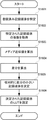
図10によれば、複写機100に設けられた操作部313のボタンによりキャリブレーション用の記録媒体の追加登録が指示されると、CPU301は、追加作業を起動する。S1001で、CPU301は、特定の記録媒体Xを選択し、特定の記録媒体Xに画像パターンを形成する。画像パターンとしては、たとえば、第2のキャリブレーションに使用される第2のテストパターンを採用できる。プリンタ部Bは、キャリブレーションに使用可能な記録媒体として任意の記録媒体を追加するために、キャリブレーションに使用可能な特定の記録媒体と任意の記録媒体とにそれぞれ同一の画像信号を用いて画像を形成する画像形成手段に相当する。S1002で、リーダ部Aは、特定の記録媒体Xに形成された画像パターンを読み取り、読み取り輝度値I(X)を生成してプリンタ制御部109のCPU301に渡す。輝度値I(X)は、特定の記録媒体に形成された画像から得られた第1輝度情報に相当する。
According to FIG. 10, when an additional registration of a recording medium for calibration is instructed by a button of the
S1003で、CPU301は、追加対象となる任意の記録媒体Zを選択し、記録媒体Zに第2のテストパターンを形成する。S1004で、リーダ部Aは、記録媒体Zに形成された画像パターンを読み取り、読み取り輝度値I(Z)を生成してプリンタ制御部109のCPU301に渡す。輝度値I(Z)は、任意の記録媒体に形成された画像から得られた第2輝度情報に相当する。読み取り輝度値I(Z)を取得するために使用される画像データ及び画像処理は、読み取り輝度値I(X)を取得するために使用されたものと同一とする。
In step S <b> 1003, the
S1005で、CPU301は、これらの読み取り輝度値I(X)及びI(Z)に次の方法を適用することで、記録媒体Zでキャリブレーションを実行する際に適用するLUTid(Z)を作成して、メモリ302または色処理部303に記憶する。LUTid(Z)の詳細な作成方法は以下の通りである。なお、LUTid(Z)は、任意の記録媒体について輝度情報を濃度情報に変換するための第2変換設定情報に相当する。
In step S <b> 1005, the
次に図11を参照する。図11(I)には、特定の記録媒体Xと任意の記録媒体Zとの出力画像信号と読み取り輝度値との関係が示されている。図11(II)には、読み取り輝度値と読み取り濃度値との関係が示されている。なお、記録媒体Zの濃度値は、記録媒体Xでの濃度値に換算されている。 Reference is now made to FIG. FIG. 11I shows the relationship between the output image signal and the read luminance value of a specific recording medium X and an arbitrary recording medium Z. FIG. 11 (II) shows the relationship between the reading luminance value and the reading density value. Note that the density value of the recording medium Z is converted to the density value of the recording medium X.
特定の記録媒体Xについての読み取り輝度値I(X)と、任意の記録媒体Zについての読み取り輝度値I(Z)は、同一の画像信号(=同じトナー載り量)で記録媒体Xと記録媒体Zに形成された画像から読み取った輝度値である。CPU301は、輝度値I(X)とI(Z)とから、同じ載り量を達成するために必要となる特定の記録媒体Xと任意の記録媒体Zとの輝度差を算出する。よって、CPU301は、第1輝度情報と第2輝度情報との差分を算出する第1算出手段として機能する。
The read luminance value I (X) for a specific recording medium X and the read luminance value I (Z) for an arbitrary recording medium Z are the same image signal (= the same amount of applied toner), and the recording medium X and the recording medium It is a luminance value read from an image formed in Z. The
CPU301は、LUTid(X)にこの輝度差を加算することで、任意の記録媒体ZについてのLUTid(Z)を作成する。よって、CPU301は、第1変換設定情報に差分を加算することで第2変換設定情報を算出する第2算出手段として機能する。LUTid(X)は、特定の記録媒体について輝度情報を濃度情報に変換するための第1変換設定情報に相当する。また、CPU301は、第1輝度情報、第2輝度情報及び第1変換設定情報を用いて第2変換設定情報を作成する作成手段として機能する。
The
図12を参照する。S1201で、CPU301は、操作部313を介して、どの記録媒体を使用するかを操作者に指定させる。S1202で、CPU301は、記録媒体Xが指定されればLUTid(X)を色処理部に設定し、記録媒体Zが指定されればLUTid(Z)を色処理部に設定する。よって、CPU301は、キャリブレーションに使用される記録媒体を指定する指定手段として機能する。S1203で、CPU301は、第1キャリブレーション(S401〜S404)及び第2キャリブレーション(S801〜S803)を実行する。とりわけ、第2キャリブレーションによって、LUTb(Z)が作成される。なお、色処理部303は、CPU301により指定された記録媒体に対応したLUTidを使用して変換処理を実行する。よって、色処理部303は、指定手段により特定の記録媒体が指定されたときは特定の記録媒体に形成された画像から得られた輝度情報を第1変換設定情報により濃度情報に変換する変換手段として機能する。また、色処理部303は、指定手段により任意の記録媒体が指定されたときは任意の記録媒体に形成された画像から得られた輝度情報を第2変換設定情報により濃度情報に変換する変換手段として機能する。
Please refer to FIG. In step S <b> 1201, the
本実施例によれば、特定の記録媒体Xの特性(輝度値I(X))、任意の記録媒体Zの特性(輝度値I(Z))、及び、記録媒体X用の第1変換設定情報(LUTid(Z))から、記録媒体Z用の第2変換設定情報(LUTid(Z))を作成する。これにより、任意の記録媒体Zを用いてキャリブレーションを実行できるようになる。とりわけ、同一の画像信号を用いて記録媒体Xと記録媒体Yとに画像を形成することで、両者におけるトナー載り量を同一にすることができる。トナー載り量が同一であるため、輝度値I(X)と輝度値I(Z)との差分は、LUTid(X)とLUTid(Z)との差分に相当する。よって、LUTid(X)に輝度値I(X)と輝度値I(Z)との差分を加算すれば、比較的に簡単に、LUTid(Z)を取得できる。 According to the present embodiment, the characteristic of the specific recording medium X (luminance value I (X)), the characteristic of the arbitrary recording medium Z (luminance value I (Z)), and the first conversion setting for the recording medium X Second conversion setting information (LUTid (Z)) for the recording medium Z is created from the information (LUTid (Z)). As a result, calibration can be executed using an arbitrary recording medium Z. In particular, by forming an image on the recording medium X and the recording medium Y using the same image signal, the amount of applied toner can be made the same. Since the applied toner amount is the same, the difference between the luminance value I (X) and the luminance value I (Z) corresponds to the difference between LUTid (X) and LUTid (Z). Therefore, if the difference between the luminance value I (X) and the luminance value I (Z) is added to LUTid (X), LUTid (Z) can be acquired relatively easily.
本実施例によれば、プリンタ部Bの単色の出力特性を精度良く所望の状態にできるため、プリンタ制御部109や外部コントローラ等でICCプロファイルを使用したカラーマネジメントを行った場合の色再現性の精度を上げることもできる。なお、ICCは、インターナショナル・カラー・コンソーシアムの略称である。
According to the present embodiment, since the output characteristics of the single color of the printer unit B can be accurately set to a desired state, the color reproducibility when color management using an ICC profile is performed by the
本実施例では、記録媒体の追加作業において記録媒体Xでの画像形成及び読み取りの後に、記録媒体Zでの画像形成及び読み取りを行うものとして説明した。しかし、記録媒体Xおよび記録媒体Zでの画像形成を先に実行し、その後に記録媒体Xおよび記録Zから画像を読み取ってもよい。記録媒体Xと記録媒体Zとのいずれが先であってもよい。 In the present embodiment, it has been described that the image formation and reading on the recording medium Z are performed after the image formation and reading on the recording medium X in the additional work of the recording medium. However, the image formation on the recording medium X and the recording medium Z may be executed first, and then the image may be read from the recording medium X and the recording Z. Either the recording medium X or the recording medium Z may be first.
なお、CPU301は、メモリ302のうち不揮発性の記憶領域(ハードディスクドライバ、EEPROMなど)に、キャリブレーション用の記録媒体の特性をテーブル化して登録してもよい。図13に示した特性テーブルでは、特性として、メディアの種類(例:普通紙、コート紙)、坪量、光沢度および白色度が採用されている。特定の記録媒体Xの特性データは、工場出荷時などに特定テーブルに書き込み可能である。また、任意の記録媒体Ziに関しては上記の追加処理の際にオペレータが操作部313を通じて入力してもよい。
Note that the
<複数の記録媒体がキャリブレーション用に登録されている場合の選択方法>
上述した追加処理を実行することで複数の任意の記録媒体Z1〜Zn(nはキャリブレーション用に登録されている任意の記録媒体の数)をプリンタ制御部109に登録することができる。CPU301は、不図示の操作部313からオペレータにより指定された記録媒体Ziに対応するLUTid(Zi)およびLUTb(Zi)を選択してプリンタ制御部109に設定する(iは1ないしnのいずれか)。もちろん、特定の記録媒体Xについても同様に設定可能である。
<Selection method when multiple recording media are registered for calibration>
By executing the additional processing described above, a plurality of arbitrary recording media Z1 to Zn (n is the number of arbitrary recording media registered for calibration) can be registered in the
しかし、複数の任意の記録媒体間でキャリブレーション精度が異なってしまうことがある。これは、演算誤差等が原因である。とりわけ、予めメーカーによって指定された特定の記録媒体に対して特性の大きく異なる記録媒体をキャリブレーション用に登録すると、キャリブレーション精度が低下しやすい。また、記録媒体Z1について決定されたパラメータ(LUTid(Z1)など)を用いて任意の記録媒体Z2を登録し、さらに、記録媒体Z2について決定されたパラメータを用いて任意の記録媒体Z3を登録すると、誤差が累積して行く。よって、任意の記録媒体の数が増えると、連鎖的に誤差が累積し、キャリブレーション精度が低下してゆく。そこで、本実施例では、複数の任意の記録媒体がキャリブレーション用に登録されている場合にキャリブレーション精度の高い記録媒体を優先的に使用できるようにする。 However, the calibration accuracy may differ between a plurality of arbitrary recording media. This is due to a calculation error or the like. In particular, if a recording medium having greatly different characteristics with respect to a specific recording medium designated in advance by a manufacturer is registered for calibration, the calibration accuracy is likely to decrease. In addition, when an arbitrary recording medium Z2 is registered using parameters determined for the recording medium Z1 (such as LUTid (Z1)), and further, an arbitrary recording medium Z3 is registered using parameters determined for the recording medium Z2. The error goes on to accumulate. Therefore, when the number of arbitrary recording media increases, errors accumulate in a chain, and the calibration accuracy decreases. Therefore, in this embodiment, when a plurality of arbitrary recording media are registered for calibration, a recording medium with high calibration accuracy can be used preferentially.
ところで、キャリブレーション精度の観点から好ましい記録媒体Ziは、各記録媒体の特性に基づいてCPU301が選択してもよいし、CPU301が各記録媒体の特性を操作部313の表示装置に表示し、それを参考にオペレータによって選択されてもよい。以下では、メディア特性の近い記録媒体を選択する機能の詳細について説明する。
Incidentally, the recording medium Zi that is preferable from the viewpoint of calibration accuracy may be selected by the
メディア特性に近いものを決定ないしは判別するために、CPU301は、メモリ302に記憶されているメディア特性表に基づき、メディア近似値を算出する。CPU301は、特定の記録媒体Xのメディア近似値と最も差の少ないメディア近似値の任意の記録媒体を、キャリブレーション用に選択する。メディア近似値の基礎となる記録媒体の特性を決定する要因としては、様々なものが考えられる。たとえば、要因としては、メディアの種類、坪量、光沢度、平滑度、白色度、剛度などがある。本実施例ではメディア近似値を求めるためのパラメータとして、階調特性への寄与度が高いと思われるメディア種類、坪量、光沢度、白色度に注目する。なお、ほかのメディア特性に関与するパラメータを追加しても、本発明の特徴は損なわれることはない。
In order to determine or discriminate what is close to the media characteristics, the
図14に示したメディア特性表には、メディア近似値を決定するために使用されるパラメータ(係数)の一例が示されている。図14に示した特性係数は、追加手段により追加された複数の任意の記録媒体におけるそれぞれの特性を示す特性情報に相当する。算出されたメディア近似値が1に近いほど、その任意の記録媒体Ziは、特定の記録媒体Xと特性が近いことを示している。反対に、メディア近似値が1から遠いほど、両者は相違している。よって、メディア近似値が1に近い記録媒体Ziを使用すれば、キャリブレーション精度が高まることが期待される。 The media characteristic table shown in FIG. 14 shows an example of parameters (coefficients) used for determining the media approximate value. The characteristic coefficient shown in FIG. 14 corresponds to characteristic information indicating each characteristic of a plurality of arbitrary recording media added by the adding unit. The closer the calculated media approximation value is to 1, the closer the recording medium Zi is to the characteristics of the specific recording medium X. Conversely, the farther the media approximation is from 1, the more different they are. Therefore, if a recording medium Zi having a media approximate value close to 1 is used, it is expected that the calibration accuracy will be improved.
図14に示したメディア近似表中の光沢度は、たとえば、ハンディ型グロスメーターPG−1M(日本電色工業株式会社製)により測定することができる。この光沢度の測定方法はJIS Z 8741に準拠している。 The glossiness in the media approximation table shown in FIG. 14 can be measured by, for example, a handy type gloss meter PG-1M (manufactured by Nippon Denshoku Industries Co., Ltd.). The method for measuring the glossiness conforms to JIS Z 8741.
図16に示してフローチャートを参照しながら、記録媒体の選択方法を以下に説明する。たとえば、図13に示した登録済み記録媒体の情報が記憶手段としてのメモリ302に格納されているものとする。S1601で、CPU301は、登録済み記録媒体情報を参照することで、登録済み記録媒体を特定する。S1602で、CPU301は、特定した記録媒体についての係数をメディア特性表から取得する。S1603で、CPU301は、特定した複数の記録媒体について取得した係数からメディア近似値を算出する。たとえば、メディア近似値は、算出対象の記録媒体の各係数を加算することで算出される。よって、CPU301は、追加手段によって追加された複数の任意の記録媒体のそれぞれについて、特性情報を構成している複数の特性係数を加算することで和を算出する加算手段として機能する。S1604で、CPU301は、各記録媒体のメディア近似値と特定の記録媒体のメディア近似値(ここでは”1”とする。)との差分を算出し、さらに差分の絶対値を決定する。よって、予め特定された記録媒体の特性を示す値と和との差分の絶対値を算出する差分手段として機能する。この差分が0に近いほど、その記録媒体はキャリブレーション精度が高いことになる。S1605で、CPU301は、特定した複数の記録媒体のうち、相対的に差分の小さい記録媒体を比較処理により決定する。よって、CPU301は、追加手段によって追加された複数の任意の記録媒体のそれぞれの差分の絶対値を比較する比較手段として機能する。
A method for selecting a recording medium will be described below with reference to the flowchart shown in FIG. For example, it is assumed that the information on the registered recording medium shown in FIG. 13 is stored in the
図15には記録媒体Z1と記録媒体Z2とについてのメディア近似値の算出例が示されている。 FIG. 15 shows an example of calculating the media approximate value for the recording medium Z1 and the recording medium Z2.
記録媒体Z1のメディア近似値 :0 + 0.3 + 0 + 0.2 + 0.5 = 0.5
記録媒体Z2のメディア近似値 :0.3 + 0.4 + 0.3 + 0 = 1.0
図15に示した例では記録媒体Z1のほうが0に近い。よって、CPU301は、記録媒体Z1を選択する。なお、複数の登録済み記録媒体間でのメディア近似値の差が階調特性としてほとんど差がでない範囲内の差であれば、このうちでどの登録済み記録媒体を選択してもよい。たとえば、CPU301は、このような登録済み記録媒体の情報を操作部313の表示装置に表示し、オペレータに選定させてもよい。CPU301は、オペレータによって選定された記録媒体をキャリブレーション用の記録媒体として選択する。このように、特定の記録媒体Xのメディア特性に最も近い任意の記録媒体でなくても、たとえば、2番目または3番目に近い他の任意の記録媒体を用いることで、階調制御を実行してもよい。なお、特定の記録媒体Xに対するメディア近似値の差分が0.2以下であれば、階調特性に現れる差は非常に少ないと考えられるからである。S1606で、CPU301は、選択した記録媒体ZiのLUTid(Zi)をプリンタ制御部109に設定する。なお、CPU301は、選択された記録媒体ZiのLUTb(Zi)は使用せずに階調制御を行う。
Media approximate value of the recording medium Z1: 0 + 0.3 + 0 + 0.2 + 0.5 = 0.5
Media approximate value of recording medium Z2: 0.3 + 0.4 + 0.3 + 0 = 1.0
In the example shown in FIG. 15, the recording medium Z1 is closer to zero. Therefore, the
このように、CPU301は、複数の任意の記録媒体におけるそれぞれの特性情報を比較することで、予め特定された記録媒体の特性に対して相対的に近似している任意の記録媒体を決定する決定手段として機能する。よって、複数の任意の記録媒体がキャリブレーション用に登録されている場合にキャリブレーション精度の高い記録媒体を優先的に使用できるようになる。特性情報としては、記録媒体の種類を示す情報、坪量を示す情報、光沢度を示す情報、白色度を示す情報、剛度を示す情報のうち少なくとも1つを利用する。これは、これらは、階調特性への寄与度が高いと思われるからである。上述したように、CPU301は、決定手段は、予め特定された記録媒体の特性に対して近似している順番にしたがって、最も近似している任意の記録媒体を含む複数の任意の記録媒体を決定してもよい。なぜんら、複数の登録済み記録媒体間でのメディア近似値の差が階調特性としてほとんど差がでない範囲内の差であれば、このうちでどの登録済み記録媒体を選択してもよいからである。また、CPU301は、操作部313の表示装置に、最も近似している任意の記録媒体を含む複数の任意の記録媒体それぞれについて特性情報の比較結果を表示させ、比較結果を見たオペレータによって入力される任意の記録媒体の選択情報を受け付けてもよい。これにより、オペレータの利便性を向上させることができよう。操作部313を通じてオペレータはどの記録媒体を選択するかを示す選択情報を入力し、CPU301がこれを受け付ける受付手段として機能する。
As described above, the
[実施例2]
実施例2では、メディア近似値の演算パラメータとして、記録媒体の登録順番を追加したことを特徴とする。明記しない構成や効果は基本的に実施例1と同様である。上述したように、特定された記録媒体Xで階調制御を行い、その後に任意の記録媒体Z1が追加される。その後は、特定の記録媒体Xを使用せずに他の任意の記録媒体Ziを追加できる。しかし、キャリブレーション用の記録媒体を順次登録して行くと、リーダ部Aの読み取りバラツキや変換誤差等の各種の誤差が累積するため、徐々にキャリブレーション精度が低下すると考えられる。よって、上述したメディア近似値が同等の2つの記録媒体が存在する場合、より先に登録された記録媒体のほうがキャリブレーション精度を向上できる可能性がある。とりわけ、特定の記録媒体Xで階調制御が行われた直後に追加された任意の記録媒体は最も誤差の蓄積が少ないといえる。
[Example 2]
The second embodiment is characterized in that the registration order of recording media is added as a calculation parameter for the media approximation value. Structures and effects not specified are basically the same as those in the first embodiment. As described above, gradation control is performed on the specified recording medium X, and then an arbitrary recording medium Z1 is added. Thereafter, another arbitrary recording medium Zi can be added without using the specific recording medium X. However, if the recording media for calibration are sequentially registered, various errors such as reading variations of the reader unit A and conversion errors accumulate, so it is considered that the calibration accuracy gradually decreases. Therefore, when there are two recording media having the same media approximation value as described above, it is possible that the recording medium registered earlier can improve the calibration accuracy. In particular, it can be said that an arbitrary recording medium added immediately after gradation control is performed on a specific recording medium X has the least error accumulation.
図17に示した実施例2に係るメディア特性表では、図14に示したメディア特性表に対して作成順番(世代)を示すデータが追加されている。よって、特性情報には、追加手段によって追加された順番を示す情報が含まれているといえる。なお、特定の記録媒体Xを用いて再度キャリブレーション(階調制御)が実行されたときは、CPU301が、各記録媒体の作成順番をリセットしてもよい。つまり、CPU301は、再び、いずれかの記録媒体の追加処理を実行する度に作成順番を振りなおして行く。このように、CPU301は、キャリブレーション実行手段が予め特定された記録媒体を使用してキャリブレーションを実行すると、追加手段によって追加された任意の記録媒体の順番を示す情報をリセットするリセット手段として機能する。
In the media characteristic table according to the second embodiment illustrated in FIG. 17, data indicating the creation order (generation) is added to the media characteristic table illustrated in FIG. 14. Therefore, it can be said that the characteristic information includes information indicating the order added by the adding unit. When calibration (gradation control) is executed again using a specific recording medium X, the
メディア近似値の実施例1と同様に、CPU301は、メディア特性表から記録媒体Ziの係数を取得して(S1601,S1602)、メディア近似値および差分を算出する(S1603,S1604)。なお、メディア近似値を算出する際には図17に示した作成順番が考慮される。なお、図17では、作成順番とそれに対応する係数とが対応付けて記憶されているが、別途、メディア種類とその作成順番とを対応付けたテーブルもメモリ302に記憶されているものとする。なお、図17に示したメディア種類の欄への各記録媒体の登録順番が作成順番にリンクしているときは、メディア種類とその作成順番とを対応付けたテーブルは不要である。
As in the first embodiment of the media approximate value, the
記録媒体Z1とZ2についてのメディア種類、坪量、光沢度、白色度、作成順番が、図18に示した係数であったと仮定すると、メディア近似値や差分は次のように算出可能である。
記録媒体Z1:
0 + 0.3 + 0 + 0.2 + 0.1 = 0.6
記録媒体Z2:
0.3 + 0.4 + 0.3 + 0 + 0 = 1
両者の差分を比較すると、記録媒体Z1のほうが0に近いことがわかる。よって、CPU301は、階調制御を行う好適なメディアとして記録媒体Z1を選択する。なお、CPU301は、各記録媒体の差分を操作部313の表示装置に表示し、それを見たオペレータによって記録媒体を選択させてもよい。なぜなら、登録されている記録媒体であっても、オペレータの手元にはない場合がある。記録媒体の差分は、一種の推薦情報となろう。よって、記録媒体の推薦情報を見たオペレータによって、オペレータの都合が良い記録媒体を選択できるようにすれば、オペレータの利便性が高まるであろう。
Assuming that the media type, basis weight, glossiness, whiteness, and creation order for the recording media Z1 and Z2 are the coefficients shown in FIG.
Recording medium Z1:
0 + 0.3 + 0 + 0.2 + 0.1 = 0.6
Recording medium Z2:
0.3 + 0.4 + 0.3 + 0 + 0 = 1
Comparing the difference between the two shows that the recording medium Z1 is closer to zero. Therefore, the
Claims (6)
前記キャリブレーションに使用可能な記録媒体として予め特定された記録媒体とは異なる任意の記録媒体を追加するために、追加する記録媒体に対応する前記変換設定情報を作成する追加手段と、
前記追加手段により追加された複数の任意の記録媒体におけるそれぞれの特性を示す特性情報を記憶する記憶手段と、
前記複数の任意の記録媒体におけるそれぞれの特性情報を前記予め特定された記録媒体の特性と比較することで、前記予め特定された記録媒体の特性に対して相対的に近似している任意の記録媒体を決定する決定手段と、を有し、
前記キャリブレーション実行手段は、前記決定手段により決定された記録媒体と、当該記録媒体に対応する前記追加手段により作成された前記変換設定情報とを使用して前記キャリブレーションを実行することを特徴とする画像形成装置。 Calibration execution means for converting a luminance value obtained from a measurement image formed on a recording medium based on conversion setting information, and executing calibration based on a result of the conversion;
Adding means for creating the conversion setting information corresponding to the recording medium to be added in order to add an arbitrary recording medium different from the recording medium specified in advance as the recording medium usable for the calibration;
Storage means for storing characteristic information indicating respective characteristics of a plurality of arbitrary recording media added by the adding means;
Arbitrary recording that is relatively approximate to the characteristics of the previously specified recording medium by comparing the characteristic information of each of the plurality of arbitrary recording media with the characteristics of the previously specified recording medium Determining means for determining a medium ;
It said calibration execution means, a recording medium determined by said determining means and Turkey to perform the calibration using the said conversion setting information created by said additional means corresponding to the recording medium An image forming apparatus.
前記追加手段によって追加された複数の任意の記録媒体のそれぞれについて、前記特性情報を構成している複数の特性係数を加算することで和を算出する加算手段と、
前記予め特定された記録媒体の特性を示す値と前記和との差分の絶対値を算出する差分手段と、
前記追加手段によって追加された複数の任意の記録媒体のそれぞれの前記差分の絶対値を比較する比較手段とを備えることを特徴とする請求項1ないし4のいずれか1項に記載の画像形成装置。 The determining means includes
For each of a plurality of arbitrary recording media added by the adding means, an adding means for calculating a sum by adding a plurality of characteristic coefficients constituting the characteristic information;
Difference means for calculating an absolute value of a difference between the value indicating the characteristic of the recording medium specified in advance and the sum;
Each of the image forming apparatus according to any one of claims 1 to 4, characterized in that it comprises a comparing means for comparing the absolute value of the difference between the plurality of arbitrary recording medium that has been added by said adding means .
前記キャリブレーションに使用可能な記録媒体として予め特定された記録媒体とは異なる任意の記録媒体を追加するための追加処理を実行する追加手段と、
前記追加手段により追加された複数の任意の記録媒体におけるそれぞれの特性を示す特性情報を記憶する記憶手段と、
前記複数の任意の記録媒体それぞれについて、前記予め特定された記録媒体の特性と前記特性情報との比較結果を表示する表示手段と、
前記比較結果を見たオペレータによって入力される任意の記録媒体の選択情報を受け付ける受付手段と、
前記受付手段によって受け付けられた選択情報に対応した任意の記録媒体を使用して前記キャリブレーションを実行するキャリブレーション実行手段とを備えることを特徴とする画像形成装置。 An image forming apparatus that performs calibration for maintaining image quality,
An adding means for executing an additional process for adding an arbitrary recording medium different from a recording medium specified in advance as a recording medium usable for the calibration;
Storage means for storing characteristic information indicating respective characteristics of a plurality of arbitrary recording media added by the adding means;
Display means for displaying a comparison result between the characteristics of the recording medium specified in advance and the characteristics information for each of the plurality of arbitrary recording media;
Receiving means for receiving selection information of an arbitrary recording medium input by an operator who has seen the comparison result;
An image forming apparatus comprising: a calibration execution unit that executes the calibration using an arbitrary recording medium corresponding to the selection information received by the reception unit .
Priority Applications (5)
| Application Number | Priority Date | Filing Date | Title |
|---|---|---|---|
| JP2009216168A JP5388772B2 (en) | 2009-09-17 | 2009-09-17 | Image forming apparatus |
| EP10175781.3A EP2309717B1 (en) | 2009-09-17 | 2010-09-08 | Calibration performed in image formation apparatus to maintain image quality |
| US12/879,373 US8995011B2 (en) | 2009-09-17 | 2010-09-10 | Calibration performed in image formation apparatus to maintain image quality |
| KR1020100090978A KR101331338B1 (en) | 2009-09-17 | 2010-09-16 | Calibration performed in image formation apparatus to maintain image quality |
| CN2010102877594A CN102023510B (en) | 2009-09-17 | 2010-09-17 | Image formation apparatus |
Applications Claiming Priority (1)
| Application Number | Priority Date | Filing Date | Title |
|---|---|---|---|
| JP2009216168A JP5388772B2 (en) | 2009-09-17 | 2009-09-17 | Image forming apparatus |
Publications (3)
| Publication Number | Publication Date |
|---|---|
| JP2011064984A JP2011064984A (en) | 2011-03-31 |
| JP2011064984A5 JP2011064984A5 (en) | 2012-11-01 |
| JP5388772B2 true JP5388772B2 (en) | 2014-01-15 |
Family
ID=43332602
Family Applications (1)
| Application Number | Title | Priority Date | Filing Date |
|---|---|---|---|
| JP2009216168A Expired - Fee Related JP5388772B2 (en) | 2009-09-17 | 2009-09-17 | Image forming apparatus |
Country Status (5)
| Country | Link |
|---|---|
| US (1) | US8995011B2 (en) |
| EP (1) | EP2309717B1 (en) |
| JP (1) | JP5388772B2 (en) |
| KR (1) | KR101331338B1 (en) |
| CN (1) | CN102023510B (en) |
Families Citing this family (20)
| Publication number | Priority date | Publication date | Assignee | Title |
|---|---|---|---|---|
| US8335013B2 (en) * | 2009-05-04 | 2012-12-18 | Kabushiki Kaisha Toshiba | System and method for color printer calibration employing measurement success feedback |
| JP5932246B2 (en) * | 2011-06-09 | 2016-06-08 | キヤノン株式会社 | Image forming apparatus |
| JP2013030937A (en) | 2011-07-27 | 2013-02-07 | Brother Ind Ltd | Image reader |
| CN102937851B (en) * | 2012-11-30 | 2016-12-21 | 上海易视计算机科技有限公司 | Electronic whiteboard image area automatic selecting method based on imageing sensor and device |
| JP6245921B2 (en) * | 2013-10-07 | 2017-12-13 | キヤノン株式会社 | Image forming apparatus |
| JP6387616B2 (en) * | 2014-01-20 | 2018-09-12 | セイコーエプソン株式会社 | Printing control method and printing control apparatus |
| JP6445871B2 (en) * | 2015-01-07 | 2018-12-26 | キヤノン株式会社 | Image forming apparatus |
| JP6465752B2 (en) * | 2015-05-29 | 2019-02-06 | キヤノン株式会社 | Control device, control method, and program |
| JP6926761B2 (en) * | 2017-07-18 | 2021-08-25 | セイコーエプソン株式会社 | Optical modules and electronic devices |
| JP6992347B2 (en) * | 2017-09-15 | 2022-01-13 | コニカミノルタ株式会社 | Image forming device, paper information calculation program and paper information calculation method |
| JP2018020575A (en) * | 2017-10-02 | 2018-02-08 | セイコーエプソン株式会社 | Printer |
| KR20190119869A (en) | 2018-04-13 | 2019-10-23 | 휴렛-팩커드 디벨롭먼트 컴퍼니, 엘.피. | printer with photodetector to detect fluorescent additives in toner |
| US10930802B2 (en) * | 2018-05-03 | 2021-02-23 | Advanced Semiconductor Engineering, Inc. | Semiconductor device package and method of manufacturing the same |
| JP2020017086A (en) * | 2018-07-25 | 2020-01-30 | 富士ゼロックス株式会社 | Print management device, and print management program |
| CN111546795B (en) * | 2019-02-12 | 2022-05-13 | 珠海艾派克微电子有限公司 | Printing control method, consumable chip and image forming system |
| EP3702968B1 (en) * | 2019-02-28 | 2023-07-05 | Canon Kabushiki Kaisha | Information processing apparatus, printing apparatus, and information processing method |
| JP7313864B2 (en) * | 2019-03-29 | 2023-07-25 | キヤノン株式会社 | Information processing device, recording device, information processing method, and program |
| JP7277211B2 (en) * | 2019-03-28 | 2023-05-18 | キヤノン株式会社 | Information processing device, recording device, information processing method, and program |
| US11218618B1 (en) * | 2020-09-24 | 2022-01-04 | Kyocera Document Solutions Inc. | Intelligent media profile management |
| US11201988B1 (en) * | 2020-09-24 | 2021-12-14 | Kyocera Document Solutions Inc. | Intelligent media profile management |
Family Cites Families (10)
| Publication number | Priority date | Publication date | Assignee | Title |
|---|---|---|---|---|
| JP3471886B2 (en) * | 1994-03-25 | 2003-12-02 | キヤノン株式会社 | Image forming method and apparatus |
| JPH08287217A (en) * | 1995-04-10 | 1996-11-01 | Canon Inc | Device and method for image recording |
| US7018008B2 (en) * | 2002-09-11 | 2006-03-28 | Canon Kabushiki Kaisha | Data processing apparatus, printing system, printing method, and computer-readable control program |
| JP2004122766A (en) | 2002-09-11 | 2004-04-22 | Canon Inc | Data processor, method of processing data, and computer readable control program |
| JP4447887B2 (en) * | 2003-10-27 | 2010-04-07 | キヤノン株式会社 | Color image forming apparatus and color stabilization control method |
| JP4284520B2 (en) | 2003-12-02 | 2009-06-24 | 富士ゼロックス株式会社 | Image forming apparatus, calibration method, and program thereof |
| JP4400715B2 (en) | 2003-12-16 | 2010-01-20 | 富士ゼロックス株式会社 | Image processing apparatus, image processing method, image processing program, and storage medium |
| JP4290131B2 (en) * | 2004-03-31 | 2009-07-01 | キヤノン株式会社 | Recording medium identification device and recording device |
| DE102006013875A1 (en) * | 2006-03-23 | 2007-11-22 | Eastman Kodak Co. | Method for creating a printing color profile |
| JP4962135B2 (en) * | 2007-05-17 | 2012-06-27 | コニカミノルタビジネステクノロジーズ株式会社 | Image forming apparatus and image density correction method |
-
2009
- 2009-09-17 JP JP2009216168A patent/JP5388772B2/en not_active Expired - Fee Related
-
2010
- 2010-09-08 EP EP10175781.3A patent/EP2309717B1/en not_active Not-in-force
- 2010-09-10 US US12/879,373 patent/US8995011B2/en not_active Expired - Fee Related
- 2010-09-16 KR KR1020100090978A patent/KR101331338B1/en active IP Right Grant
- 2010-09-17 CN CN2010102877594A patent/CN102023510B/en not_active Expired - Fee Related
Also Published As
| Publication number | Publication date |
|---|---|
| EP2309717B1 (en) | 2015-11-11 |
| EP2309717A3 (en) | 2011-10-26 |
| KR101331338B1 (en) | 2013-11-19 |
| US8995011B2 (en) | 2015-03-31 |
| CN102023510A (en) | 2011-04-20 |
| JP2011064984A (en) | 2011-03-31 |
| EP2309717A2 (en) | 2011-04-13 |
| US20110063640A1 (en) | 2011-03-17 |
| KR20110030394A (en) | 2011-03-23 |
| CN102023510B (en) | 2013-12-11 |
Similar Documents
| Publication | Publication Date | Title |
|---|---|---|
| JP5388772B2 (en) | Image forming apparatus | |
| US9659242B2 (en) | Apparatus that performs calibration for maintaining image quality | |
| JP5143254B2 (en) | Image forming apparatus | |
| JP5676965B2 (en) | Image forming apparatus | |
| JP5932246B2 (en) | Image forming apparatus | |
| JP5430364B2 (en) | Image forming apparatus | |
| US9516196B2 (en) | Image forming apparatus that performs calibration for maintaining image quality | |
| US9210298B2 (en) | Image forming apparatus which performs calibration for maintaining image quality | |
| JP5247058B2 (en) | Image forming apparatus | |
| JP2014199344A (en) | Image forming apparatus |
Legal Events
| Date | Code | Title | Description |
|---|---|---|---|
| A521 | Written amendment |
Free format text: JAPANESE INTERMEDIATE CODE: A523 Effective date: 20120914 |
|
| A621 | Written request for application examination |
Free format text: JAPANESE INTERMEDIATE CODE: A621 Effective date: 20120914 |
|
| A131 | Notification of reasons for refusal |
Free format text: JAPANESE INTERMEDIATE CODE: A131 Effective date: 20130517 |
|
| A977 | Report on retrieval |
Free format text: JAPANESE INTERMEDIATE CODE: A971007 Effective date: 20130522 |
|
| A521 | Written amendment |
Free format text: JAPANESE INTERMEDIATE CODE: A523 Effective date: 20130709 |
|
| TRDD | Decision of grant or rejection written | ||
| A01 | Written decision to grant a patent or to grant a registration (utility model) |
Free format text: JAPANESE INTERMEDIATE CODE: A01 Effective date: 20130909 |
|
| A61 | First payment of annual fees (during grant procedure) |
Free format text: JAPANESE INTERMEDIATE CODE: A61 Effective date: 20131008 |
|
| R151 | Written notification of patent or utility model registration |
Ref document number: 5388772 Country of ref document: JP Free format text: JAPANESE INTERMEDIATE CODE: R151 |
|
| LAPS | Cancellation because of no payment of annual fees |