JP5388529B2 - Wireless communication device - Google Patents
Wireless communication device Download PDFInfo
- Publication number
- JP5388529B2 JP5388529B2 JP2008253015A JP2008253015A JP5388529B2 JP 5388529 B2 JP5388529 B2 JP 5388529B2 JP 2008253015 A JP2008253015 A JP 2008253015A JP 2008253015 A JP2008253015 A JP 2008253015A JP 5388529 B2 JP5388529 B2 JP 5388529B2
- Authority
- JP
- Japan
- Prior art keywords
- value
- mimo
- cqi
- transmission
- wireless communication
- Prior art date
- Legal status (The legal status is an assumption and is not a legal conclusion. Google has not performed a legal analysis and makes no representation as to the accuracy of the status listed.)
- Active
Links
Images


Classifications
-
- H—ELECTRICITY
- H04—ELECTRIC COMMUNICATION TECHNIQUE
- H04B—TRANSMISSION
- H04B7/00—Radio transmission systems, i.e. using radiation field
- H04B7/02—Diversity systems; Multi-antenna system, i.e. transmission or reception using multiple antennas
- H04B7/04—Diversity systems; Multi-antenna system, i.e. transmission or reception using multiple antennas using two or more spaced independent antennas
- H04B7/0413—MIMO systems
- H04B7/0417—Feedback systems
-
- H—ELECTRICITY
- H04—ELECTRIC COMMUNICATION TECHNIQUE
- H04B—TRANSMISSION
- H04B7/00—Radio transmission systems, i.e. using radiation field
- H04B7/02—Diversity systems; Multi-antenna system, i.e. transmission or reception using multiple antennas
- H04B7/04—Diversity systems; Multi-antenna system, i.e. transmission or reception using multiple antennas using two or more spaced independent antennas
- H04B7/06—Diversity systems; Multi-antenna system, i.e. transmission or reception using multiple antennas using two or more spaced independent antennas at the transmitting station
- H04B7/0686—Hybrid systems, i.e. switching and simultaneous transmission
- H04B7/0689—Hybrid systems, i.e. switching and simultaneous transmission using different transmission schemes, at least one of them being a diversity transmission scheme
-
- H—ELECTRICITY
- H04—ELECTRIC COMMUNICATION TECHNIQUE
- H04L—TRANSMISSION OF DIGITAL INFORMATION, e.g. TELEGRAPHIC COMMUNICATION
- H04L1/00—Arrangements for detecting or preventing errors in the information received
- H04L1/0001—Systems modifying transmission characteristics according to link quality, e.g. power backoff
- H04L1/0002—Systems modifying transmission characteristics according to link quality, e.g. power backoff by adapting the transmission rate
- H04L1/0003—Systems modifying transmission characteristics according to link quality, e.g. power backoff by adapting the transmission rate by switching between different modulation schemes
-
- H—ELECTRICITY
- H04—ELECTRIC COMMUNICATION TECHNIQUE
- H04L—TRANSMISSION OF DIGITAL INFORMATION, e.g. TELEGRAPHIC COMMUNICATION
- H04L1/00—Arrangements for detecting or preventing errors in the information received
- H04L1/0001—Systems modifying transmission characteristics according to link quality, e.g. power backoff
- H04L1/0009—Systems modifying transmission characteristics according to link quality, e.g. power backoff by adapting the channel coding
-
- H—ELECTRICITY
- H04—ELECTRIC COMMUNICATION TECHNIQUE
- H04L—TRANSMISSION OF DIGITAL INFORMATION, e.g. TELEGRAPHIC COMMUNICATION
- H04L1/00—Arrangements for detecting or preventing errors in the information received
- H04L1/0001—Systems modifying transmission characteristics according to link quality, e.g. power backoff
- H04L1/0015—Systems modifying transmission characteristics according to link quality, e.g. power backoff characterised by the adaptation strategy
- H04L1/0016—Systems modifying transmission characteristics according to link quality, e.g. power backoff characterised by the adaptation strategy involving special memory structures, e.g. look-up tables
-
- H—ELECTRICITY
- H04—ELECTRIC COMMUNICATION TECHNIQUE
- H04L—TRANSMISSION OF DIGITAL INFORMATION, e.g. TELEGRAPHIC COMMUNICATION
- H04L1/00—Arrangements for detecting or preventing errors in the information received
- H04L1/02—Arrangements for detecting or preventing errors in the information received by diversity reception
- H04L1/06—Arrangements for detecting or preventing errors in the information received by diversity reception using space diversity
- H04L1/0618—Space-time coding
- H04L1/0637—Properties of the code
- H04L1/0643—Properties of the code block codes
-
- H—ELECTRICITY
- H04—ELECTRIC COMMUNICATION TECHNIQUE
- H04B—TRANSMISSION
- H04B7/00—Radio transmission systems, i.e. using radiation field
- H04B7/02—Diversity systems; Multi-antenna system, i.e. transmission or reception using multiple antennas
- H04B7/04—Diversity systems; Multi-antenna system, i.e. transmission or reception using multiple antennas using two or more spaced independent antennas
- H04B7/06—Diversity systems; Multi-antenna system, i.e. transmission or reception using multiple antennas using two or more spaced independent antennas at the transmitting station
- H04B7/0613—Diversity systems; Multi-antenna system, i.e. transmission or reception using multiple antennas using two or more spaced independent antennas at the transmitting station using simultaneous transmission
- H04B7/0615—Diversity systems; Multi-antenna system, i.e. transmission or reception using multiple antennas using two or more spaced independent antennas at the transmitting station using simultaneous transmission of weighted versions of same signal
- H04B7/0619—Diversity systems; Multi-antenna system, i.e. transmission or reception using multiple antennas using two or more spaced independent antennas at the transmitting station using simultaneous transmission of weighted versions of same signal using feedback from receiving side
- H04B7/0621—Feedback content
- H04B7/0632—Channel quality parameters, e.g. channel quality indicator [CQI]
-
- H—ELECTRICITY
- H04—ELECTRIC COMMUNICATION TECHNIQUE
- H04B—TRANSMISSION
- H04B7/00—Radio transmission systems, i.e. using radiation field
- H04B7/02—Diversity systems; Multi-antenna system, i.e. transmission or reception using multiple antennas
- H04B7/04—Diversity systems; Multi-antenna system, i.e. transmission or reception using multiple antennas using two or more spaced independent antennas
- H04B7/06—Diversity systems; Multi-antenna system, i.e. transmission or reception using multiple antennas using two or more spaced independent antennas at the transmitting station
- H04B7/0613—Diversity systems; Multi-antenna system, i.e. transmission or reception using multiple antennas using two or more spaced independent antennas at the transmitting station using simultaneous transmission
- H04B7/0667—Diversity systems; Multi-antenna system, i.e. transmission or reception using multiple antennas using two or more spaced independent antennas at the transmitting station using simultaneous transmission of delayed versions of same signal
- H04B7/0669—Diversity systems; Multi-antenna system, i.e. transmission or reception using multiple antennas using two or more spaced independent antennas at the transmitting station using simultaneous transmission of delayed versions of same signal using different channel coding between antennas
-
- H—ELECTRICITY
- H04—ELECTRIC COMMUNICATION TECHNIQUE
- H04B—TRANSMISSION
- H04B7/00—Radio transmission systems, i.e. using radiation field
- H04B7/02—Diversity systems; Multi-antenna system, i.e. transmission or reception using multiple antennas
- H04B7/04—Diversity systems; Multi-antenna system, i.e. transmission or reception using multiple antennas using two or more spaced independent antennas
- H04B7/06—Diversity systems; Multi-antenna system, i.e. transmission or reception using multiple antennas using two or more spaced independent antennas at the transmitting station
- H04B7/0697—Diversity systems; Multi-antenna system, i.e. transmission or reception using multiple antennas using two or more spaced independent antennas at the transmitting station using spatial multiplexing
-
- H—ELECTRICITY
- H04—ELECTRIC COMMUNICATION TECHNIQUE
- H04L—TRANSMISSION OF DIGITAL INFORMATION, e.g. TELEGRAPHIC COMMUNICATION
- H04L1/00—Arrangements for detecting or preventing errors in the information received
- H04L1/0001—Systems modifying transmission characteristics according to link quality, e.g. power backoff
- H04L1/0023—Systems modifying transmission characteristics according to link quality, e.g. power backoff characterised by the signalling
- H04L1/0026—Transmission of channel quality indication
-
- H—ELECTRICITY
- H04—ELECTRIC COMMUNICATION TECHNIQUE
- H04L—TRANSMISSION OF DIGITAL INFORMATION, e.g. TELEGRAPHIC COMMUNICATION
- H04L1/00—Arrangements for detecting or preventing errors in the information received
- H04L1/12—Arrangements for detecting or preventing errors in the information received by using return channel
- H04L1/16—Arrangements for detecting or preventing errors in the information received by using return channel in which the return channel carries supervisory signals, e.g. repetition request signals
- H04L1/18—Automatic repetition systems, e.g. Van Duuren systems
- H04L1/1812—Hybrid protocols; Hybrid automatic repeat request [HARQ]
Description
本発明は、複数の通信方式を切り替えて使用する無線通信装置、および、その送信方法の切り替え技術に関する。 The present invention relates to a wireless communication apparatus that switches between and uses a plurality of communication methods, and a transmission method switching technique thereof.
移動通信など、無線伝搬路が変動する環境における無線通信方式として、複数のMIMO(Multiple Input Multiple Output)通信方式、符号化方式、変調方式などを適応的に切り替えて通信を行う技術が知られている。更に、切り替えを行う際の選択基準を実際の通信状況にあわせて変更する技術として、たとえば、特許文献1があげられる。特許文献1では、受信信号対干渉電力比(Signal to Interference power Ratio:SIR)を用いて、変調符号化(Modulation and Coding Scheme:MCS)レベルを切り替える方法、および、MCSレベルを切り替えるための受信SIRの基準値を、通信状況にあわせて制御する方法の記載がある。なお、本件発明者等はこの技術分野における関連発明としてMIMO通信方式の改良に関する特許文献2を出願している。
As a wireless communication method in an environment where the wireless propagation path fluctuates such as mobile communication, a technology for performing communication by adaptively switching a plurality of MIMO (Multiple Input Multiple Output) communication methods, encoding methods, modulation methods, etc. is known. Yes. Furthermore, as a technique for changing the selection criteria for switching according to the actual communication status, for example,
また、非特許文献1には、SM, STCに対応するモードとして、“spatial multiplexing”、および、“transmit diversity”が記載されている。
Non-Patent
前記の特許文献1の技術においては、MCSレベルを切り替える際に、個々の移動機の受信性能に合わせて基準値を変更しているが、基準値の変更については高い通信スループットを保つように基準値を変更することが望ましい。また、無線通信機が複数のMIMO通信方式に対応する場合において、MIMO通信方式と符号化、変調方式のすべてを適切に切り替える方法が必要となる。
In the technology of
本発明では、複数のMIMO通信方式を利用する無線通信装置において、複数のMIMO通信方式、および、符号化、変調方式を高いスループットが得られるように適切に切り替える方法、及びそれを利用した無線通信装置を提供することを目的とする。 In the present invention, in a wireless communication device using a plurality of MIMO communication systems, a plurality of MIMO communication systems, a method for appropriately switching between encoding and modulation systems so as to obtain high throughput, and wireless communication using the same An object is to provide an apparatus.
本発明では、上記目的を達成するために、複数のMIMO方式を切り替えて使用する場合において、現時点で使用されていないMIMO方式、符号化方式、変調方式の組み合わせに対して、推定値を使用することで、伝搬路の統計的性質が変化した場合においても、適切なMIMO方式、符号化方式、変調方式が選択できるようにする。 In the present invention, in order to achieve the above object, when switching between a plurality of MIMO systems, estimated values are used for combinations of MIMO systems, encoding systems, and modulation systems that are not currently used. Thus, even when the statistical property of the propagation path changes, an appropriate MIMO system, encoding system, and modulation system can be selected.
すなわち、本発明においては、複数のMIMO通信方式、符号化方式、変調方式を切り替えて通信を行うMIMO通信装置の送信方法切り替え方法であって、MIMO通信装置は、現時点の切り替え基準では使用されないMIMO通信方式、符号化方式、変調方式の組み合わせに対して、使用されているMIMO通信方式、符号化方式、変調方式の組み合わせの通信結果からの推定値をもって、使用されていないMIMO通信方式、符号化方式、変調方式を切り替える基準を変更する送信方法切り替え方法を提供する。 That is, in the present invention, a transmission method switching method of a MIMO communication apparatus that performs communication by switching between a plurality of MIMO communication schemes, encoding schemes, and modulation schemes, and the MIMO communication apparatus is not used in the current switching criterion. For combinations of communication methods, encoding methods, and modulation methods, MIMO communication methods and encodings that are not used, with estimated values from communication results of combinations of MIMO communication methods, encoding methods, and modulation methods used Provided is a transmission method switching method for changing a standard for switching a method and a modulation method.
また、本発明においては、複数のMIMO通信方式、符号化方式、変調方式を切り替えて通信を行う無線通信装置であって、無線周波数回路部と、この無線周波数回路部が受信した受信信号を復調・復号する復調・復号部と、送信データを符号化・変調する符号化変調部と、復調・復号部が受信信号から抽出したCQI(Channel Quality Information)値に基づき、複数のMIMO通信方式、符号化方式、変調方式を選択する処理部とを有し、この処理部は、CQI値に対応する、複数のMIMO通信方式各々の平均レートと、MIMO通信方式各々における符号化方式、変調方式を示すMCS値とを記憶し、CQI値に基づき決定したMIMO通信方式に従い、送信データの送信のための符号化方式、変調方式を選択し、選択した符号化方式、変調方式に基づき、送信データを送信するよう制御し、且つ、処理部は、送信回数と通信の成否に応じて、選択したMIMO通信方式のMCS値を変更すると共に、選択されなかったMIMO通信方式のMCS値を推定値により更新する無線通信装置を提供する。 Further, in the present invention, a radio communication apparatus that performs communication by switching a plurality of MIMO communication systems, encoding systems, and modulation systems, and demodulates a radio frequency circuit unit and a reception signal received by the radio frequency circuit unit Demodulation / decoding unit for decoding, encoding / modulation unit for encoding / modulating transmission data, and multiple MIMO communication systems and codes based on CQI (Channel Quality Information) values extracted from the received signal by the demodulation / decoding unit And a processing unit for selecting an encoding method and a modulation method, and this processing unit indicates an average rate of each of a plurality of MIMO communication methods corresponding to a CQI value, and an encoding method and a modulation method in each of the MIMO communication methods. Stores the MCS value, selects the encoding method and modulation method for transmission data transmission according to the MIMO communication method determined based on the CQI value, and transmits the transmission data based on the selected encoding method and modulation method Control to In addition, the processing unit provides a wireless communication device that changes the MCS value of the selected MIMO communication method according to the number of transmissions and the success or failure of communication, and updates the MCS value of the MIMO communication method that has not been selected with the estimated value. To do.
本発明によれば、複数のMIMO通信方式、および、符号化、変調方式を高いスループットが得られるように適切に切り替える方法、及びその方法を利用した無線通信装置が提供される。 According to the present invention, there are provided a method of appropriately switching a plurality of MIMO communication schemes and encoding and modulation schemes so as to obtain a high throughput, and a radio communication apparatus using the method.
まず、本発明が適用される無線通信装置について説明する。無線通信装置は、図1に示すように、送信側無線通信機1が複数のアンテナ2-1,2-2から信号を送信し、無線伝搬路を介して受信側無線通信機4が複数のアンテナ3-1,3-2を用いて送信された信号を受信する構成を有する。
First, a wireless communication apparatus to which the present invention is applied will be described. As shown in FIG. 1, in the wireless communication device, the transmission-side
図1では、送信アンテナ、受信アンテナがそれぞれ2本の場合について図示しているが、それ以外の本数の組み合わせであってもよく、また、送信アンテナの数と受信アンテナの数が異なっていても良い。図1の伝搬路においては、送信アンテナ2-1から送信された信号は、それぞれ、受信アンテナ3-1,3-2に複素利得h11,h12で到達し、送信アンテナ2-2から送信された信号は、それぞれ、受信アンテナ3-1,3-2に複素利得h21,h22で到達するものとする。このような伝搬路を、h11〜h22を要素とする複素利得行列Hを用いて表現する。 Although FIG. 1 shows a case where there are two transmitting antennas and two receiving antennas, other combinations may be used, and the number of transmitting antennas may be different from the number of receiving antennas. good. In the propagation path of FIG. 1, the signals transmitted from the transmitting antenna 2-1 reach the receiving antennas 3-1 and 3-2 with complex gains h11 and h12, respectively, and are transmitted from the transmitting antenna 2-2. Assume that the signals reach the receiving antennas 3-1 and 3-2 with complex gains h21 and h22, respectively. Such a propagation path is expressed using a complex gain matrix H whose elements are h11 to h22.
なお、以下の説明において、通信方式として、MIMO通信方式を例示して説明するが、これに限定されるものでないことは言うまでもない。また、伝搬路の「実効レート(スループット)」を「実測レート」や「平均レート」と呼ぶ場合がある点に留意されたい。 In the following description, the MIMO communication method is exemplified as the communication method, but it goes without saying that the present invention is not limited to this. It should be noted that the “effective rate (throughput)” of the propagation path may be referred to as “measured rate” or “average rate”.
第1の実施例の無線通信装置においては、複数の符号化方式、変調方式を切り替えて通信を行うため、送信回数および通信成否に応じて符号化方式、変調方式を切り替える基準を変更する構成を有する。 In the wireless communication apparatus of the first embodiment, in order to perform communication by switching between a plurality of encoding schemes and modulation schemes, a configuration for changing the reference for switching between the encoding scheme and the modulation scheme according to the number of transmissions and the success or failure of communication is configured. Have.
図2に、第1の実施例である無線通信装置の送信側無線通信機1の機能構成を示すブロック図を示す。送信側無線通信機1は、前述のように複数のアンテナ2-1,2-2,2-3等を用いて信号を送信するが、本実施例においては、複数の通信モードとしてMIMO通信方式の複数の信号の乗せ方(MIMOモード)が選択できるものとする。例えば、並列伝送により高速通信が可能なSM (Spatial Multiplexing)モードと、安定通信が可能なSTC (Space-Time Coding)モードを選択して伝送する場合を考える。なお、これ以外にも信号を伝搬路行列Hの特異ベクトルにしたがって信号をマッピングする固有モード伝送や、4本またはそれ以上のアンテナ本数で安定通信を実現するSTBC(Space-Time Block Code)モード等の他のMIMOモードを用いても良いことは言うまでない。
FIG. 2 is a block diagram showing a functional configuration of the transmission-side
まず、送信側無線通信機1が受信側無線通信機4にデータを送信する場合、前もって受信側無線通信機4から通知されている通信路品質情報(Channel Quality Information:CQI)を参照する。CQIは、アンテナ2-1,2-2,2-3等で受信された信号を無線周波数回路16、復調器17-1を介して分離器(De-MUX)18に供給し分離することで得られる。送信側無線通信機1は、CQIを用いて、CQIが良い通信路品質を示している時は高速の通信、悪い通信路品質を示している時は低速の通信を行うように動作する。このために、MIMO方式決定部14は、現在通知されているCQIに対して、SMモードとSTCモードのどのMIMOモードが最も高いレートで通信できるかを、実測レートテーブル13を用いて判定し、選択する。
First, when the transmission-side
次にMIMO方式決定部14の判定結果に従い、適応変調符号化 (Adaptive Modulation and Coding:AMC)テーブル制御部15が、選択したMIMOモードについて現在のCQIに適した符号化方法、および、変調方法を決定する。
Next, according to the determination result of the MIMO
送信データはバッファ/スケジューラ10に一度保持され、適当なタイミングで符号化器11に供給される。符号化器11は、AMCテーブル制御部15で決定された符号化方法で符号化を行い、符号化結果を変調器12に供給する。変調器12は、同様に決定された変調方式、及び、MIMOモードに従って変調処理を行い、無線周波数回路16を介して複数のアンテナ2-1,2-2,2-3等から信号を送信する。
The transmission data is once held in the buffer / scheduler 10 and supplied to the
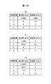
実測レートテーブル13は、例えば、図4に示すようなテーブルを保持している。図4の例ではCQIが0〜31の32通りの値をもっており、それぞれのCQIについて、STCモードで送信した場合に期待できる平均(通信)レートR_STC(n)と、SMモードで送信した場合に期待できる平均(通信)レートR_SM(n)を格納している。これらは、下式1で表される。 The actual measurement rate table 13 holds, for example, a table as shown in FIG. In the example of FIG. 4, CQI has 32 values from 0 to 31, and for each CQI, the average (communication) rate R_STC (n) that can be expected when transmitted in STC mode, and when transmitted in SM mode It stores the expected average (communication) rate R_SM (n). These are represented by Formula 1 below.

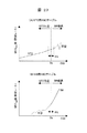
すなわち、CQIが与えられれば、STCモードとSMモードのどちらを用いるとより高い通信レートが得られるかが判断できる。これにより、実測レートテーブル13が保持する平均レートが、例えば図6のようになっていた場合、本実施例のMIMO方式決定部14において、横軸上の閾値ThよりもCQIが大きな場合にはSMモードが、ThよりもCQIが小さな場合にはSTCモードが選ばれることになる。
That is, if CQI is given, it can be determined whether a higher communication rate can be obtained by using the STC mode or the SM mode. Thereby, when the average rate held in the actual measurement rate table 13 is as shown in FIG. 6, for example, when the CQI is larger than the threshold Th on the horizontal axis in the MIMO
また、前述のAMCテーブル制御部15は、例えば、図5に示すようなAMCテーブル(STC/SM)を保持している。図5の例では、0〜31の32通りのCQIに対して、どのような符号化方式・変調方式を使うのが適切であるかを示すMCS(Modulation and Coding Scheme)値を保持しており、AMCテーブル制御部15は、CQIとMIMO方式、本実施例ではSTCモードまたはSMモードが与えられると、適切な符号化方式・変調方式を選択できるようになっている。
Further, the above-described AMC
なお、図2の送信側無線通信機1の機能ブロック図において、実測レートテーブル13、MIMO方式決定部14、AMCテーブル制御部15は、送信側無線通信機1内の図示が省略された、通常の中央処理部(Central Processing Unit:CPU)と記憶部(メモリ)で構成される。AMCテーブル(STC/SM)などの各種テーブルは記憶部(メモリ)中に記憶され、これらのテーブルの内容に基づく判定、選択、決定は、処理部であるCPUにおけるプログラム処理によって実行可能であることは言うまでもない。
In the functional block diagram of the transmitting side
次に、図14に図2に示した符号化器11の一構成例を示す。図14は、ターボ符号を用いた符号化器の一例である。送信データはまず誤り検出符号付加部37にて、誤り検出符号を付加する。次にターボ符号器38にて2つの再帰的畳み込み符号器54,56とインタリーバ55によって符号化され符号語U,Y1,Y2を出力する。更にパラレル・シリアル(P/S)変換器39にて一連の符号語として出力する。更に、パンクチャ部40は、AMCテーブル制御部15で内部のテーブルを参照して決定された符号化方式に従って、符号語の一部を削除して符号化結果として出力する。例えば、畳み込み符号器54,56が符号化率1/2の符号化器であった場合、符号語は、1ビットの情報ビットUに対して2ビットの冗長ビットY1、及び、2ビットの冗長ビットY2の割合で構成される。このまま、まったくパンクチャを行わなければ符号化率は1/5、Y1,Y2それぞれの半数を削除すれば符号化率は1/3、Y1,Y2のそれぞれ3/4を削除すれば符号化率は1/2となる。このようにして符号化率を制御された符号語を符号化結果として出力する際、出力するビット列の順番を入れ替えるインタリーブ処理を同時に施すことが望ましい。
Next, FIG. 14 shows a configuration example of the
図7に図2に示した変調器12の一構成例を示す。符号化器11から出力されたビット列(b0,b1,b2,…)は、シンボルマッパ31にて決定された変調方法に従って変調され、I(実数)成分、Q(虚数)成分からなる複素信号(s0,s1,s2,…)に変換される。シンボルマッパ31の動作例を図8に示す。上から64QAM, 16QAM, QPSKの3種類の変調方式の動作を示している。64QAMでは(b0,b1,…,b5)の6bitを一まとめとして64通りのビットの組み合わせをI,Q複素平面上の64点にマッピングして出力信号I+jQ(変調シンボル)を得る。同様に16QAMでは(b0,b1,b2,b3)の4bitを16点に、QPSKでは(b0,b1)の2bitを4点にマッピングする。引き続き供給されるビット列に対しても、変調単位(上記、6bit, 4bit, 2bit等)毎に繰り返し変調処理を行う。
FIG. 7 shows a configuration example of the
図7(A)において、シンボルマッパ31から出力された変調シンボルは、MIMOマッパ32によって複数のアンテナにマッピングされる。MIMOマッパ32は、決定されたMIMOモードに従って、対応する信号マッピングを行う。図7(A)は、送信アンテナが2本の場合で、かつ、SMモードの場合の例を示している。図7(A)の例では、各変調シンボルは交互に2つのアンテナに振り分けられ、一つ目のアンテナに対しては、偶数番目の変調シンボル、二つ目のアンテナに対しては奇数番目の変調シンボルが割り振られ、並列化により2倍の伝送速度が得られるようになる。
In FIG. 7 (A), the modulation symbols output from the
図7(B)は、STCモードの場合の例(Alamoutiの方法)を示している。STCモードでは、各変調シンボルは両方のアンテナに割り振られ、それぞれ異なる乗せ方で送信される。即ち、一つ目のアンテナからはs0,-s1*,s2,-s3*,…、二つ目のアンテナからはs1,s0*,s3,s2*,…が送出されるようになる。ここで、記号*は複素共役を表すものとする。STCモードでは、同じ信号が両方のアンテナから送信されるため、安定度の高い通信が得られる。 FIG. 7B shows an example in the STC mode (Alamouti method). In STC mode, each modulation symbol is allocated to both antennas and transmitted in different ways. That is, s0, -s1 *, s2, -s3 *, ... are transmitted from the first antenna, and s1, s0 *, s3, s2 *, ... are transmitted from the second antenna. Here, the symbol * represents a complex conjugate. In the STC mode, since the same signal is transmitted from both antennas, highly stable communication can be obtained.
各アンテナにマッピングされた変調シンボル列であるデータ変調信号は、基準信号挿入部33において、受信側無線通信機4で参照される基準信号を挿入する。図9に図7中の基準信号挿入部33の動作を示す。MIMOマッパ32にて出力された送信アンテナ本数分(図9ではM本)のデータ変調信号D-1〜D-Mは、定期的に基準信号P-1〜P-Mが挿入される。データ変調信号D-1〜D-Mは、送信データによって作られる信号で、送信データによって変化するため受信側では未知であるが、基準信号P-1〜P-Mは、システムで決められた既知の信号であり、次に説明する受信側のチャネル推定部にてチャネル推定を行う際の参照信号として用いられる。
In the data modulation signal that is a modulation symbol string mapped to each antenna, the reference
図3に本実施例の無線通信装置の受信側無線通信機4の機能構成を示すブロック図を示す。複数のアンテナ3-1,3-2,3-3で受信された受信信号は、無線周波数回路16を介して基準信号抽出部20および復調器17に供給される。基準信号抽出部20は、前述の送信側無線通信機1で挿入された基準信号(P-1,P-2,…,P-M)を分離・抽出する。分離抽出された基準信号(P-1,P-2,…,P-M)は、チャネル(伝搬路)推定部21に供給され、伝搬路の特性が測定される。測定される伝搬路の特性は、送信側無線通信機1のアンテナ2-1,2-2,2-3等と受信側無線通信機のアンテナ3-1,3-2,3-3等間の前述した複素利得行列Hや、雑音レベル等である。
FIG. 3 is a block diagram showing a functional configuration of the reception-side
測定された伝搬路特性を用いて、CQI算出部22は伝搬路の品質(Channel Quality)をあらわす制御信号であるCQI (Channel Quality Information)を算出する。これは単に受信された基準信号(P-1,P-2,…,P-M)の平均的な信号対雑音電力比(Signal to Noise Ratio:SNR)に基づく制御情報であってもよいし、どの程度の通信速度で通信できそうであるかを示したチャネル容量(伝搬路容量)の推定値に基づく制御情報であってもよい。
Using the measured propagation path characteristics, the
ここで、基準信号抽出部20、チャネル推定部21、CQI算出部22は、受信側無線通信機4内の、先の送信側無線通信機1内と同様に図示を省略した、処理部であるCPUと、記憶部としてデータ・プログラムを記憶するメモリで実現可能であることは言うまでもない。
Here, the reference
さて、本実施例の構成において、算出されたCQIは通信に先立ち、もしくは、定期的に多重化器23、変調器12-1、無線周波数回路16、アンテナ3-1,3-2,3-3等を介して送信側無線通信機1に伝達される。前述のとおり、送信側無線通信機1においては、このCQIを用いて決定されたMIMOモード、符号化方式、変調方式を用いて、受信側無線通信機4あての信号が送信される。
Now, in the configuration of the present embodiment, the calculated CQI is prior to communication or periodically, the
送信側無線通信機1から送信された受信側無線通信機4あての信号は、複数のアンテナ3-1,3-2,3-3、無線周波数回路16を介して基準信号抽出部20および復調器17に供給される。再び、基準信号抽出部20において抽出された基準信号(P-1,P-2,…,P-M)を用いてチャネル推定部21は最新の伝搬路の特性を測定し、復調器17に供給する。復調器17は、測定された最新の伝搬路の特性に基づき、受信信号を復調し復号器19に供給する。復号器19は誤り訂正復号を行い、復調信号に含まれる誤りを訂正する。復号器19で復号された受信信号は、誤り判定部24にて復号結果に誤りが含まれるかどうかを判定して、送信側無線通信機1に受信成功を示すACK、もしくは受信失敗を示すNACKを、多重化器23、変調器12-1、無線周波数回路16、アンテナ3-1,3-2,3-3等を介して制御情報として返送する。
A signal transmitted from the transmission side
前述のように、送信側無線通信機1は、返送された受信結果(ACK/NACK)を用いて、受信が成功(ACK)していれば、現在のデータの送信を完了し、次のデータの送信を行う。受信が失敗(NACK)していれば、現在のデータの再送信を行う。再送信方法としては、まったく同じデータを再度送信する方法であってもよいし、送信側無線通信機1の図14に示した符号化器11のパンクチャ部40で削除された冗長ビットを追加送信する方法であってもよい。
As described above, the transmission side
図10に、本実施例の受信側無線通信機4の復調器17の一構成例を示す。図10は、アンテナが2本の場合について記載している。2本のアンテナからの受信信号(x0,x1,x2,…)および(y0,y1,y2,…)はMIMO復調部34に供給される。MIMO復調部34は、チャネル推定部21で測定された複素利得行列Hを用いてMIMOモードに応じて図11に示すMIMO復調処理を行う。
FIG. 10 shows a configuration example of the
たとえば、MIMOモードが前述のSTCモードであった場合、図11(A)に示す演算により復調を行うことが出来る。また、MIMOモードがSMモードであった場合、図11(B)に示す演算により復調を行うことが出来る。図11(B)において、αは受信信号の信号対雑音電力比SNRによって定まる定数である。図11(B)は、最小平均2乗誤差(Minimum Mean Square Error:MMSE)規範に基づくMIMO復調を示しているが、SMモードに対応した他の復調方式、たとえばZero Forcingなどであってもよい。また、後述のシンボルデマッパ36と一括した処理による最尤検出法(Maximum Likelihood Detection:MLD)とすることも出来る。
For example, when the MIMO mode is the above-described STC mode, demodulation can be performed by the calculation shown in FIG. Further, when the MIMO mode is the SM mode, demodulation can be performed by the calculation shown in FIG. In FIG. 11B, α is a constant determined by the signal-to-noise power ratio SNR of the received signal. FIG. 11B shows MIMO demodulation based on the Minimum Mean Square Error (MMSE) standard, but other demodulation schemes corresponding to the SM mode, such as Zero Forcing, may be used. . Alternatively, a maximum likelihood detection method (Maximum Likelihood Detection: MLD) can be performed by processing together with a
図10(A)は、再送時にまったく同じデータを送信した場合に対応した復調処理を示している。図10(A)では、MIMO復調の結果(r0,r1,r2,…)は、H-ARQ (Hybrid ARQ)合成部35に供給される。H-ARQ合成部35は、前記再送信が行われるたびに前回までのMIMO復調結果と今回の復調結果を合成し、合成結果(r0’,r1’,r2’,…)を出力する。同じ受信データが受信されているはずであるから、受信信号を加算することでより品質のよい受信結果を得ることが出来る。H-AQR合成結果(r0’,r1’,r2’,…)は、シンボルデマッパ36に供給され、変調方式に応じてビット復調結果に分離する処理を行い、ビット尤度情報を出力する。
FIG. 10 (A) shows a demodulation process corresponding to the case where exactly the same data is transmitted at the time of retransmission. In FIG. 10A, the result of MIMO demodulation (r0, r1, r2,...) Is supplied to the H-ARQ (Hybrid ARQ)
図12にシンボルデマッパ36の動作を模式的に示す。図12では16QAMの場合の動作を示しているが、他の変調方式においても同様である。(b0,b1,b2,b3)の4bitの復調結果を得るにあたり、図中、四角の点で示す受信信号点(受信シンボル)から、b0=0に対応する変調信号点、b0=1に対応する変調信号点のうちもっとも近い物をそれぞれ選択し、受信信号点(受信シンボル)からの距離をそれぞれ測定し、L00, L01とする。この結果より、b0の受信信号尤度としてL00^2-L01^2を出力する。b1〜b3についても同様である。
FIG. 12 schematically shows the operation of the
また、復調器17は図10(B)のように構成することも出来る。図10(B)の構成は、再送信時にまったく同じデータを送る場合以外に、前述した追加の冗長ビットを送信する方式の場合に用いることが出来る。図10(B)の構成では、MIMO復調結果(r0,r1,r2,…)は、シンボルデマッパ36に供給され、ビット尤度に変換される。ビット尤度情報は、H-ARQ合成部35’に供給され、再送信号の合成処理が行われる。同じデータが送信されている場合は、各ビットの尤度に対して図10(A)で説明したのと同様にそれぞれ再送信されるたびに尤度情報を加算により合成する。また、追加の冗長ビットが行われた場合は、前回の復調結果であるビット尤度に、追加で送られた冗長ビットの尤度を組み合わせてより信頼性の高い復調結果を得る。
The
また、図10(A)に示す復調処理においてMMSE復調を行う場合は、図13に示すようにMIMO復調処理34とH-ARQ合成部35の処理を一括して行うことで、それぞれを独立して行う場合よりも更に特性のよい復調処理を行うことが出来る。図13の例では、MIMO復調を行う前に、伝搬路行列の段階でH-ARQの合成処理を行っている。すなわち、累算器51、52でそれぞれ再送信時の受信信号と伝搬路行列の合成を行い、処理部53においてMMSE処理を行っている。この構成は、再送信時に伝搬路行列Hが変化している場合に特によい特性を示す。
Also, when performing MMSE demodulation in the demodulation process shown in FIG. 10 (A), the
図15に本実施例の受信側無線通信機4に用いられる復号器19の一構成例を示す。復調器17で復調された受信した一連の信号は、デパンクチャ部41において、符号語のうち送信側で削除された部分を追加して出力する。この際、これらのビットは実際には送信されていないため、ビット尤度を0とする。デパンクチャ処理後、シリアル・パラレル(S/P)変換器42にてU’,Y1’,Y2’に分離され、ターボ復号器43にて復号処理を受け、復号結果U’’を出力する。この際、CC (Convolutional Code)復号器57, 59とインタリーバ58,61、デインタリーバ60を繰り返し用いた繰り返し復号により受信誤りが訂正される。なお、送信側のパンクチャ部40でインタリーブ処理が施されている場合は、前述のデパンクチャ部41にてビット列の順番を元に戻すデインタリーブ処理を同時に施すものとする。
FIG. 15 shows a configuration example of the
次に、図16A、図16Bを用いて、本実施例の送信側無線通信機1で実行される、MIMOなどの通信方式、符号化方式、変調方式の決定法、および、平均レートテーブルとAMCテーブルの更新方法について詳述する。これらは、図2に示した送信側無線通信機1の実測レートテーブル13、MIMO方式決定部14、AMCテーブル制御部15を用いて行われる。図16A、Bに示された処理フローは、先に説明した送信側無線通信機1内の処理部である図示されないCPUにおけるプログラム処理として実効可能であることは言うまでもない。
Next, using FIG. 16A and FIG. 16B, a communication method such as MIMO, a coding method, a method for determining a modulation method, an average rate table and an AMC, which are executed by the transmitting-side
図16Aにおいて、処理部は、送信要求が発生した場合、手順101にて最新のCQIを抽出する。抽出されたCQI値をqとすると、手順103にて実測レートテーブル13が保持する平均レートを参照し、どのMIMOモードを用いることでより高いスループット(平均レート、実効レート)が得られるかを判定する。判定結果に基づき手順104-1、104-2にて、MIMO方式決定部14がMIMOモードを決定する。AMCテーブル制御部15は、決定されたMIMOモードに従い、図5にその一例を示したAMCテーブルを参照し、手順105-1、105-2にてMCS値を決定する。本実施例では、前述のとおりMIMOモードとして、STCモードおよびSMモードが選択可能なものとしているが、これに限定されず、他の通信モードであっても良いことは言うまでもない。
In FIG. 16A, when a transmission request occurs, the processing unit extracts the latest CQI in
なお、図5に示したAMCテーブルは連続的な値を保持するので、図示されない処理部は、図16Aの手順107にて送信側無線通信機1および受信側無線通信機2が実際に使用する離散的なMCS値に変換する。手順107は、たとえば図17に示すような階段状の関数を用いて、AMCテーブル15が保持するMCS値を超えない最大の離散MCS値に変換することで実現される。図17において、横軸はAMCテーブル値、縦軸はMCS値(設定レート)である。
Since the AMC table shown in FIG. 5 holds continuous values, the processing unit (not shown) is actually used by the transmission-side
離散化されたMCS値をmとすると、手順108にて図18に示すようなMCSテーブルを参照して、符号化方式(CODE(m))、変調方式(MOD(m))が選択される。なお、このMCSテーブルには、図示されない記憶部(メモリ)に記憶されており、AMCテーブル制御部15として機能する処理部が、記憶部からMCS値に対応する符号化・変調方式を読み出し、符号化器11、変調器12に制御信号として入力する。
Assuming that the discretized MCS value is m, the encoding method (CODE (m)) and the modulation method (MOD (m)) are selected by referring to the MCS table as shown in FIG. 18 in
さて、手順108に続いて、図16Bの手順109にて、送信(再送)回数をカウントするカウンタnが1に初期化される。手順110にて、決定されたMIMOモード、符号化方式、変調方式に従って、図2の無線周波数回路16から送信が行われる。手順111にて、先に説明した受信側無線通信機4からの受信成功・失敗を通知する制御信号(ACK/NACK)を待つ。
Following the
そして、受信側無線通信機4からの通知が受信失敗(NACK)を示す場合は、手順113-1、113-2にて、使用したMCS値を現在の送信回数に応じて受信失敗時の更新(変更)量D_F(n)だけ変更する。送信回数が、予定した最大回数(max)に満たない場合は、更にカウンタnに1を加算して手順110に戻り、n回目の再送信を実施する。また、受信が成功(ACK)した場合は、手順116-1、116-2により、やはり、送信回数nに応じて、使用したMCS値を受信成功時の更新量D_S(n)だけ変更する。
If the notification from the receiving side
このMCS値の変更は、AMCテーブル制御部15として機能する処理部であるCPUのプログラム処理で実行する。本実施例において、この受信失敗時の更新量D_F(n)、受信成功時の更新量D_S(n)は、図19にその一例を示すように、送信回数nによってそれぞれ異なる値をとる。図19では、最大4回(max=4)まで送信を行う場合についての前記の更新量D_F(n)、D_S(n)を例示する。これらの更新量のテーブルについても、図示されない記憶部であるメモリに記憶されており、AMCテーブル制御部15として機能するCPUが、受信の成功・失敗、及び送信回数に対応する更新量を読み出すこととなる。
The change of the MCS value is executed by the program processing of the CPU that is a processing unit that functions as the AMC
本実施例において、AMCテーブル制御部15が手順113-1、113-2、116-1、116-2に従い、AMCテーブルが保持するMCS値を更新するのは、伝搬路の統計的性質が異なる場合には、同じCQIに対しても選択すべきMCSが異なるからである。たとえば、CQIが非常に正確で、CQI通知によって最適な通信レートすなわちMCSが一通りに決まる場合は、1回目の送信でほぼ確実に受信が成功するようにすることが出来る。しかしながら、伝搬路のばらつきが大きくCQIの誤差が大きい場合は、通知されたCQIから判定される通信レートよりも低い通信レートでしか通信できない場合もあれば、より高い通信レートで通信できる可能性もある。この場合、一回目の送信で確実に受信できるようなMCS値を選択すると、平均的に得られる通信レートよりも低い通信レートでしか通信できなくなってしまう。
In this embodiment, the AMC
そこで、CQIが誤差を含むような場合や、CQIのみでは正確に通信レートが判定できないような場合は、まず、ある程度高めの通信レートとなるMCSで送信を行ってみて、結果として成功すれば、選択した高めの通信レートが得られるし、失敗した場合は、再送信により救済するようにすることが望ましい。すなわち、CQIが正確、かつ、CQIのみで正しく通信レートが判定できる場合は、1回目の送信の成功確率を非常に高く設定することが適切であり、反対に、CQIが不正確もしくはCQIのみでは正しく通信レートが判定できないような場合には、1回目は失敗する確率がある程度高いことを覚悟しても受信が成功する可能性のある範囲で高めの通信レートを選択することが適切である。 So, if the CQI contains an error, or if the communication rate cannot be determined accurately with CQI alone, first try sending with MCS, which is a somewhat higher communication rate, and if it succeeds as a result, The selected higher communication rate can be obtained, and in the case of failure, it is desirable to rescue by re-transmission. In other words, if CQI is accurate and the communication rate can be determined correctly only by CQI, it is appropriate to set the success probability of the first transmission to be very high, and conversely, if CQI is incorrect or only CQI If the communication rate cannot be determined correctly, it is appropriate to select a higher communication rate within a range where reception is likely to succeed even if the probability of failure is high to some extent at the first time.
しかしながら、一般的に通信レートを高く設定しすぎると、再送によっても救済が出来ない程度に再送の連鎖が発生してしまう。このため、MCSの選択に当たっては、再送の連鎖が起きない程度に高い通信レートを選択することが望ましい。すなわち、AMCテーブルが保持するMCS値を適切に変更するためのMCS値の変更は、送信(再送)回数によってどのように失敗、成功の確率が変化するかを鑑みてなされるべきである。このような観点から、本実施例では、失敗時、成功時共に、送信回数nに応じてMCS値の更新量D_F(n)、D_S(n)は異なる値としている。 However, in general, if the communication rate is set too high, a retransmission chain occurs to the extent that relief cannot be achieved by retransmission. For this reason, when selecting an MCS, it is desirable to select a communication rate that is high enough not to cause a retransmission chain. That is, the change of the MCS value for appropriately changing the MCS value held in the AMC table should be made in view of how the probability of failure and success changes depending on the number of transmissions (retransmissions). From this point of view, in this embodiment, the MCS value update amounts D_F (n) and D_S (n) are different values depending on the number of times of transmission, both at the time of failure and at the time of success.
図19に示す更新量は、たとえば図20の(A)、(B)、(C)のように設定することが好ましい。図20(A)に示す更新量のテーブルでは、1回目の送信時には、送信に成功しても失敗してもMCSを高めに変更するように、更新量は正の値に設定されている。一方2回目の送信が失敗した場合にはMCSを低下させるように負の値が設定されている。それ以外の場合には、MCS値を変更しないように更新量を0としている。この結果、図20(A)の場合においては、一回目の受信失敗の頻度と、二回目の受信失敗頻度が約100:1になった場合に、MCS値の増加量の期待値と減少量の期待値がほぼ等しくなり、MCS値が収束した状態となる。すなわち、図20(A)の場合、一回目の失敗は許容する代わりに、再送の連鎖が起きないように、再送を行った場合の失敗頻度を抑えるように動作する。 For example, the update amounts shown in FIG. 19 are preferably set as shown in (A), (B), and (C) of FIG. In the update amount table shown in FIG. 20 (A), at the first transmission, the update amount is set to a positive value so that the MCS is changed to a higher value regardless of whether the transmission is successful or failed. On the other hand, if the second transmission fails, a negative value is set so as to lower the MCS. In other cases, the update amount is set to 0 so that the MCS value is not changed. As a result, in the case of FIG. 20 (A), when the frequency of the first reception failure and the frequency of the second reception failure are about 100: 1, the expected increase value and the decrease amount of the MCS value are about 100: 1. The expected values of are almost equal and the MCS value has converged. That is, in the case of FIG. 20 (A), instead of allowing the first failure, the operation is performed so as to suppress the failure frequency when retransmission is performed so that the retransmission chain does not occur.
図20(B)についてもほぼ同様の効果を期待できる。すなわち、一回目の送信時はMCSの微小増加のみが発生するが、二回目の成功と失敗の確率を約100:1になるようにMCS値が制御される。図20(C)の例では、二回目の送信で成功する確率と三回目の送信で成功する確率をやはり約100:1になるように制御される。また、図20(C)では、最大回数(4回)の送信を行っても成功しなかった場合には、MCS値を低下させるようになっている。以上のように、送信・再送信を繰り返した場合の成功、失敗の発生頻度をバランスさせることにより、再送の連鎖が起きない範囲でMCS値を高めに設定するようにMCS値の更新量テーブルを設定することが望ましい。 Similar effects can be expected for FIG. 20 (B). That is, only a small increase in MCS occurs at the first transmission, but the MCS value is controlled so that the probability of success and failure at the second time is about 100: 1. In the example of FIG. 20 (C), the probability of success in the second transmission and the probability of success in the third transmission are also controlled to be about 100: 1. In FIG. 20 (C), if the maximum number of transmissions (four times) is not successful, the MCS value is decreased. As described above, the MCS value update amount table is set so that the MCS value is set higher in a range where retransmission chain does not occur by balancing the frequency of success and failure when transmission / retransmission is repeated. It is desirable to set.
さて、本実施例において、受信成功時、または、送信回数が最大回数に達した場合、図16Bの手順118-1、118-2にてこれまでに実際に通信できた平均レート(スループット)を保持する図4の実測レートテーブルの該当する平均レート値R_STC(q)またはR_SM(q)を更新する。 In this embodiment, when reception is successful or when the number of transmissions reaches the maximum number, the average rate (throughput) that can actually be communicated so far in steps 118-1 and 118-2 in FIG. The corresponding average rate value R_STC (q) or R_SM (q) in the actually measured rate table of FIG. 4 is updated.
また、上述してきた処理において、後述のテーブル更新時に参照するための参照頻度情報として、図21のようなCQIとMIMOモードの組み合わせについての使用頻度情報WTを図16Aの手順102、手順106-1、106-2で更新する。手順102、手順106-1、106-2は、忘却係数(1-k)を用いた使用頻度測定を行い、近い過去に使用頻度が高かった場合に使用頻度情報WTが大きな値を持つように計算される。
Further, in the processing described above, as reference frequency information to be referred to when updating a table, which will be described later, the use frequency information WT for the combination of CQI and MIMO mode as shown in FIG. 21 is used as
続いて、本実施例の図16Bの手順117-1、117-2、119-1、119-2においても、AMCテーブルの更新、および、実測レートテーブルの平均レートの更新が行われる。これらの更新は上述した使用頻度情報WTを参照して行われる。この手順117-1、117-2、119-1、119-2のテーブル更新の目的は、現在は使用されていないが、伝搬路の統計的性質の変化によって将来使用されるかもしれないテーブル値を適切に設定することにある。現在使用されているMIMOモードのMCS値は、上述したように、手順113-1、113-2、116-1、116-2によって更新され、また、平均レートは手順118-1、118-2によって更新されるため、適切な値を保持している。 Subsequently, also in the procedures 117-1, 117-2, 119-1, and 119-2 in FIG. 16B of the present embodiment, the AMC table is updated and the average rate of the actually measured rate table is updated. These updates are performed with reference to the use frequency information WT described above. The purpose of this table 117-1, 117-2, 119-1, 119-2 is to update the table values that are not currently used but may be used in the future due to changes in the statistical properties of the channel. Is to set it appropriately. The MCS value of the currently used MIMO mode is updated by steps 113-1, 113-2, 116-1, 116-2 as described above, and the average rate is updated by steps 118-1, 118-2. It is updated by, so it holds an appropriate value.
しかしながら、図16Aの手順103の比較の結果使用されなかったMIMOモードのMCS値、および、平均レート値は更新されていない。これらが、今後も使用されないのであれば正しい値を保持する必要はないことになるが、伝搬路の統計的性質が変化することによって、AMCテーブルの最適値や平均レートが変化する場合を考えると、使用していなかったMIMOモードに対するMCS値、平均レート値も正しく保守されていることが必要となる。このため、本実施例においては、手順117-1、117-2、119-1、119-2では、現在使用したCQIの近傍(q±L)に使用頻度の低いCQIがあった場合には、そのCQIに対応したMCS値、および、平均レート値を、推定値を用いて更新する。この推定方法としては、線形近似による外挿や、より高次の近時による外挿などの公知の手法を用いることが出来る。このために、例えば、現在使用したCQIの近傍(q±L)の内、図21の使用頻度情報が一定以上の値をもつCQIについての平均レートテーブル(図4)値、AMCテーブル(図5)値を用いて、平均レート値、及び、MCS値のCQIに対する回帰曲線(または回帰直線)をそれぞれ算出し、現在使用したCQIの近傍(q±L)の内、図21の使用頻度情報が一定以下の値を持つCQIについての平均レートテーブル(図4)値、AMCテーブル(図5)値を前記、回帰曲線(または回帰直線)を用いて推定することができる。また、回帰曲線(または回帰直線)の算出において、使用頻度情報WTに応じた重みで回帰計算することや、推定値を使用頻度情報WTの逆の重みに応じて更新を行うことも望ましい。
However, the MCS value and the average rate value in the MIMO mode that are not used as a result of the comparison in the
この結果、実測レートテーブルの平均レートについては図22、AMCテーブルについては図23(A)、(B)に示すように、MIMOモードの切り替えポイントThの近傍(±L)にわたって推定値による値が保持されるようになる。±L以上離れたCQIに対しては、推定値による更新を行わないので、値は不定となるが、伝搬路の統計的性質の変動は徐々に発生すると考えられるので、変動した場合もまずは切り替えポイントThの近傍のCQIが使用されるようになり、その値が正しく更新されるようになり、切り替えポイントThが移動し、更に、その近傍が推定されてゆくので、推定値による更新は切り替えポイントThの近傍のみで十分である。 As a result, as shown in FIG. 22 for the average rate in the actually measured rate table and in FIGS. 23 (A) and (B) for the AMC table, the estimated value over the vicinity (± L) of the switching point Th in the MIMO mode is It will be held. The CQI that is more than ± L away is not updated by the estimated value, so the value is indeterminate, but the statistical properties of the propagation path are expected to change gradually. The CQI in the vicinity of the point Th will be used, its value will be updated correctly, the switching point Th will move, and the neighborhood will be estimated, so the update by the estimated value will be updated Only the vicinity of Th is sufficient.
なお、手順117-1、117-2、119-1、119-2では、使用頻度情報WTに基づき推定値による更新を行うかどうかを判定しているが、図24(A)、(B)に示す例の場合のように、現在のMIMOモード選択の基準である実測レートテーブル13を参照して、近傍CQI(q±L)について使用されていないテーブル値であるかどうかを判定(手順120-1、120-2)し、使用されていない場合には、外挿による推定値をもってAMCテーブル、平均レートテーブルのMCS値、平均レート値等を更新(手順121-1、121-2、122-1、122-2)するようにしてもよい。この場合は、図21に示した使用頻度テーブル、ならびに、手順102、106-1、106-2の使用頻度テーブルの更新手順は不要となる。
In steps 117-1, 117-2, 119-1, and 119-2, it is determined whether or not to update the estimated value based on the usage frequency information WT. FIG. 24 (A), (B) As in the example shown in FIG. 4, it is determined whether or not the table value is not used for the neighboring CQI (q ± L) with reference to the actually measured rate table 13 that is the criterion for the current MIMO mode selection (step 120). -1, 120-2), and if not used, update the AMC table, MCS value of the average rate table, average rate value, etc. with the extrapolated estimated values (procedures 121-1, 121-2, 122) -1, 122-2). In this case, the procedure for updating the usage frequency table shown in FIG. 21 and the usage frequency table in
以上、本発明の実施の形態として、2つのMIMOモード(SM、 STC)についての動作を記載したが、これ以外にも信号を伝搬路行列Hの特異ベクトルにしたがって信号をマッピングする固有モード伝送や、4本またはそれ以上のアンテナ本数で安定通信を実現するSTBC (Space-Time Block Code)伝送等の他のMIMO伝送方法であっても良い。例えば、上記の非特許文献1には、前記、SM, STCに対応するモードとして、“spatial multiplexing”、および、“transmit diversity”が記載されているが、それぞれが更に同時送信信号数(Number of Layers)と符号語数(Number of code word)の複数の組み合わせによるMIMO方式が定義されており、“spatial multiplexing”で5通り、“transmit diversity”で2通りの計7通りのMIMO方式が存在する。これら7通りのMIMO方式の内、どれを選択して伝送を行うかを決定する際にも本願発明を適用することが効果的である。この場合、図4、図5、図21などSM, STCの2モードについて値を保持しているテーブルを7モードについてそれぞれ値を保持するように構成し、図16Aの手順103にて2つの平均レートを比較する代わりに7つの平均レートを比較して最も大きな平均レートが得られる方式を選択して手順104以降を実行するようにすれば良い。
As described above, the operation for the two MIMO modes (SM, STC) has been described as an embodiment of the present invention.Other than this, eigenmode transmission for mapping a signal according to a singular vector of the propagation path matrix H, Other MIMO transmission methods such as STBC (Space-Time Block Code) transmission that realizes stable communication with four or more antennas may be used. For example, in
更に、複数の受信側無線通信機に対して同時に空間多重伝送を行うMIMO伝送モードを持つようなシステムにおいても同様である。例えば、送信側無線通信機が2本の送信アンテナを持ち、受信側無線通信機が2本の受信アンテナを持つ場合、1つの信号をSTCにて1台の受信側無線通信機に対して送信する第一のモード、2つの信号をSMにて1台の受信側無線通信機に対して送信する第二のモード、2つの信号を空間分割多重にて2台の受信側無線通信機に対して送信する第三のモードが選択可能となる。この場合も、やはり、3つのMIMOモードそれぞれについて平均レートテーブル(図4)、AMCテーブル(図5)、使用頻度テーブル(図21)を作成し、最も高い合計平均レート(複数の受信側無線通信機の合計)が得られるモードを図16Aの手順103にて選択するようにすれば良い。なお、受信側無線通信機ごとに保証すべき最低レートを考慮する必要がある場合には、その制約内で合計平均レートが最大となるMIMOモードを図16Aの手順103にて選択する。
The same applies to a system having a MIMO transmission mode in which spatial multiplexing transmission is simultaneously performed for a plurality of receiving-side wireless communication devices. For example, if the transmitting wireless communication device has two transmitting antennas and the receiving wireless communication device has two receiving antennas, one signal is transmitted to one receiving wireless communication device via STC. The first mode to perform, the second mode to transmit two signals to one receiving wireless communication device via SM, and the two signals to two receiving wireless communication devices by space division multiplexing The third mode of transmission can be selected. Again, the average rate table (Fig. 4), AMC table (Fig. 5), and usage frequency table (Fig. 21) are created for each of the three MIMO modes, and the highest total average rate (multiple receiving side radio communications The mode in which the total number of machines) is obtained may be selected in
以上、本発明によれば、複数のMIMO通信方式を利用する無線通信装置において、複数のMIMO通信方式、および、符号化、変調方式を、伝搬路の統計的性質が変化した場合においても高いスループットが得られるように適切に切り替える方法、及びそれを利用した無線通信装置を提供することができる。 As described above, according to the present invention, in a wireless communication device using a plurality of MIMO communication schemes, a plurality of MIMO communication schemes and encoding and modulation schemes can be used even when the statistical properties of the propagation path change. It is possible to provide a method for appropriately switching so as to obtain the above and a wireless communication apparatus using the method.
1…送信側無線通信機、
2-1〜2-3、3-1〜3-3…アンテナ、
4…受信側無線通信機、
10…バッファ/スケジューラ、
11、11-1…符号化器、
12、12-1…変調器、
13…実測レートテーブル、
14…MIMO方式決定部、
15…AMCテーブル、
16…無線周波数(RF)回路、
17、17-1…復調器、
18…分離器(De-MUX)、
19、19-1…復号器、
20…基準信号抽出部、
21…チャネル推定部、
22…CQI算出部、
23…多重化器(MUX)、
24…誤り判定部、
31…シンボルマッパ、
32…MIMOマッパ、
33…基準信号挿入部、
34、34-1…MIMO復調部、
35、35’ …H-ARQ合成部、
36…シンボルデマッパ、
37…誤り検出符号付加部、
38…ターボ復号器、
39…パラレル・シリアル(P/S)変換器、
40…パンクチャ部、
41…デパンクチャ部、
42…シリアル・パラレル(S/P)変換器、
43…ターボ復号器。
1 ... Sending wireless communication device,
2-1 to 2-3, 3-1 to 3-3 ... antenna,
4 ... Receiving side wireless communication device,
10 ... buffer / scheduler,
11, 11-1 ... Encoder,
12, 12-1 ... Modulator,
13 ... Actual rate table,
14 ... MIMO system decision part,
15 ... AMC table,
16 ... Radio frequency (RF) circuit,
17, 17-1 ... demodulator,
18… Separator (De-MUX),
19, 19-1 ... Decoder,
20 ... reference signal extraction unit,
21 ... Channel estimation unit,
22 ... CQI calculator,
23: Multiplexer (MUX),
24 ... error judgment part,
31 ... Symbol mapper,
32… MIMO Mapper,
33 ... reference signal insertion part,
34, 34-1 ... MIMO demodulator,
35, 35 '… H-ARQ synthesis unit,
36… Symbol demapper,
37: Error detection code adding unit,
38 ... turbo decoder,
39… Parallel serial (P / S) converter,
40 ... Puncture club,
41 ... depuncture club,
42 ... Serial / Parallel (S / P) converter,
43 ... Turbo decoder.
Claims (3)
無線周波数回路部と、
前記無線周波数回路部が受信した受信信号を復調・復号する復調・復号部と、
送信データを符号化・変調する符号化変調部と、
前記復調・復号部が前記受信信号から抽出したCQI値に基づき、前記複数のMIMO通信方式、符号化方式、変調方式を選択する処理部と
を有し、
前記処理部は、前記CQI値に対応する、複数の前記MIMO通信方式各々の平均レートと、
前記複数のMIMO通信方式の各々における前記符号化方式、変調方式の組み合わせを示すMCS値とを記憶し、
前記抽出したCQI値に基づき決定した前記MIMO通信方式に従い、前記送信データの送信のための符号化方式及び変調方式の組み合わせを選択して前記送信データを送信するよう制御し、
前記処理部は、送信回数と前記送信の成否に応じて、使用した前記MIMO通信方式の使用した前記MCS値を更新し、前記更新したMCS値を用いて、前記複数のMIMO通信方式を切り替える基準を更新する
ことを特徴とする無線通信装置。 According to CQI (Channel Quality Information) value, a plurality of MIMO (Multiple Input Multiple Output) communication schemes, a plurality of encoding schemes, a wireless communication device that performs communication by switching a combination of modulation schemes ,
A radio frequency circuit section;
A demodulation / decoding unit that demodulates and decodes a received signal received by the radio frequency circuit unit;
An encoding and modulation unit for encoding and modulating transmission data;
Based on the CQI value extracted from the received signal by the demodulation / decoding unit, a processing unit that selects the plurality of MIMO communication methods, encoding methods, and modulation methods;
Have
The processing unit corresponds to the CQI value, an average rate of each of the plurality of MIMO communication methods,
Storing the MCS value indicating the combination of the encoding scheme and the modulation scheme in each of the plurality of MIMO communication schemes;
According to the MIMO communication scheme determined based on the extracted CQI value, control the transmission data to be transmitted by selecting a combination of encoding scheme and modulation scheme for transmission of the transmission data,
The processing unit updates the MCS value used by the used MIMO communication method according to the number of transmissions and the success or failure of the transmission, and uses the updated MCS value to switch the plurality of MIMO communication methods. Update
A wireless communication apparatus .
前記処理部は、
前記複数のMIMO通信方式各々における前記CQI値と前記平均レートとの対応を示す実測レートテーブルと、
前記複数のMIMO通信方式各々における前記CQI値と前記符号化方式、変調方式の対応を示すAMCテーブルと、
前記CQI値を用いて前記実測レートテーブルから前記MIMO通信方式を決定する通信方式決定部と、
前記決定したMIMO通信方式と前記CQI値を用いて前記AMCテーブルから前記符号化方式、変調方式を選択するAMCテーブル制御部と、
前記送信の成功、または失敗を示す信号と送信回数とに応じて、前記符号化方式、変調方式を切り替える基準を変更する更新量を記憶するMCS値更新量テーブルとを備え、
前記送信の受信成功時、または前記送信回数が予め設定した値に達したとき、前記送信に使用した前記MIMO通信方式の使用した前記CQI値に対応する平均レートを更新し、前記更新した平均レートに基づき、前記使用したMIMO通信方式の使用していない前記CQI値に対応する平均レートを推定して更新する
ことを特徴とする無線通信装置。 The wireless communication device according to claim 1,
The processor is
An actual measurement rate table showing correspondence between the CQI value and the average rate in each of the plurality of MIMO communication systems;
An AMC table indicating correspondence between the CQI value and the encoding scheme and modulation scheme in each of the plurality of MIMO communication schemes;
A communication method determination unit for determining the MIMO communication method from the measured rate table using the CQI value;
An AMC table control unit that selects the encoding scheme and modulation scheme from the AMC table using the determined MIMO communication scheme and the CQI value;
According to the signal indicating the success or failure of the transmission and the number of transmissions, the MCS value update amount table storing an update amount for changing a reference for switching the coding method and modulation method,
When reception of the transmission is successful or when the number of transmissions reaches a preset value, the average rate corresponding to the CQI value used by the MIMO communication method used for the transmission is updated, and the updated average rate is updated. Based on the above, the average rate corresponding to the CQI value not used by the used MIMO communication method is estimated and updated.
A wireless communication apparatus .
前記複数のMIMO通信方式はSMモード、STCモード、固有モード伝送、STBCモードの内、何れか2つを含み、前記CQI値は、信号対雑音電力比に基づく制御情報、あるいはチャネル容量の推定値に基づく制御情報であり、
前記処理部は、前記MCS値更新量テーブルに従い、前記使用したMIMO通信方式の前記使用したMCS値を変更し、前記使用したCQI値の近傍に使用頻度の低いCQI値があった場合、前記使用頻度の低いCQI値に対応した前記MCS値、及び前記平均レートを、前記変更されたMCS値からの推定値を用いて更新する
ことを特徴とする無線通信装置。 The wireless communication device according to claim 2,
The plurality of MIMO communication methods include any two of SM mode, STC mode, eigenmode transmission, and STBC mode, and the CQI value is control information based on a signal-to-noise power ratio or an estimated value of channel capacity Control information based on
The processing unit changes the used MCS value of the used MIMO communication method according to the MCS value update amount table, and when there is a CQI value with low use frequency in the vicinity of the used CQI value, the use The MCS value corresponding to the infrequent CQI value and the average rate are updated using the estimated value from the changed MCS value.
A wireless communication apparatus .
Priority Applications (2)
| Application Number | Priority Date | Filing Date | Title |
|---|---|---|---|
| JP2008253015A JP5388529B2 (en) | 2008-09-30 | 2008-09-30 | Wireless communication device |
| US12/554,149 US8451923B2 (en) | 2008-09-30 | 2009-09-04 | MIMO transmission mode selecting method and wireless communication equipment |
Applications Claiming Priority (1)
| Application Number | Priority Date | Filing Date | Title |
|---|---|---|---|
| JP2008253015A JP5388529B2 (en) | 2008-09-30 | 2008-09-30 | Wireless communication device |
Publications (2)
| Publication Number | Publication Date |
|---|---|
| JP2010087727A JP2010087727A (en) | 2010-04-15 |
| JP5388529B2 true JP5388529B2 (en) | 2014-01-15 |
Family
ID=42057482
Family Applications (1)
| Application Number | Title | Priority Date | Filing Date |
|---|---|---|---|
| JP2008253015A Active JP5388529B2 (en) | 2008-09-30 | 2008-09-30 | Wireless communication device |
Country Status (2)
| Country | Link |
|---|---|
| US (1) | US8451923B2 (en) |
| JP (1) | JP5388529B2 (en) |
Families Citing this family (7)
| Publication number | Priority date | Publication date | Assignee | Title |
|---|---|---|---|---|
| US8908632B2 (en) | 2007-06-08 | 2014-12-09 | Samsung Electronics Co., Ltd. | Methods and apparatus for channel interleaving in OFDM systems |
| JP2010212822A (en) * | 2009-03-09 | 2010-09-24 | Toshiba Corp | Communication system, transmission apparatus, and receiving device, apparatus |
| CN101990315B (en) * | 2009-08-04 | 2013-08-07 | 中兴通讯股份有限公司 | Method and equipment for adjusting downlink modulation coding mode and multi-input multi-output mode |
| CN102377508B (en) * | 2010-08-13 | 2015-06-10 | 中兴通讯股份有限公司 | Adaptive modulation and coding method and adaptive modulation and coding device |
| JP5487090B2 (en) * | 2010-12-03 | 2014-05-07 | 株式会社日立製作所 | Radio signal processing method and radio communication apparatus |
| US9270348B2 (en) * | 2011-04-20 | 2016-02-23 | Lg Electronics Inc. | Method of transmitting and receiving MIMO feedback information in wireless communication system, mobile station and base station |
| GB2514174B (en) * | 2013-05-17 | 2015-12-02 | Cambium Networks Ltd | Improvements to adaptive modulation |
Family Cites Families (8)
| Publication number | Priority date | Publication date | Assignee | Title |
|---|---|---|---|---|
| JP4016647B2 (en) * | 2001-05-17 | 2007-12-05 | 日本電気株式会社 | Mobile communication system, base station, mobile station, threshold setting method used therefor, and program thereof |
| JP2003143654A (en) | 2001-11-02 | 2003-05-16 | Ntt Docomo Inc | Mobile communication method and mobile communication system |
| JP4256207B2 (en) * | 2002-06-28 | 2009-04-22 | パナソニック株式会社 | Transmitting apparatus and communication mode selection table updating method |
| US8218609B2 (en) * | 2002-10-25 | 2012-07-10 | Qualcomm Incorporated | Closed-loop rate control for a multi-channel communication system |
| JP2004266586A (en) | 2003-03-03 | 2004-09-24 | Hitachi Ltd | Data transmitting and receiving method of mobile communication system |
| JP4884722B2 (en) * | 2005-03-31 | 2012-02-29 | 株式会社エヌ・ティ・ティ・ドコモ | Wireless communication apparatus and wireless communication method |
| JP4994706B2 (en) * | 2006-05-12 | 2012-08-08 | 三菱電機株式会社 | Wireless communication apparatus and data transmission method |
| JP5217212B2 (en) * | 2007-03-30 | 2013-06-19 | 富士電機株式会社 | Boost chopper |
-
2008
- 2008-09-30 JP JP2008253015A patent/JP5388529B2/en active Active
-
2009
- 2009-09-04 US US12/554,149 patent/US8451923B2/en not_active Expired - Fee Related
Also Published As
| Publication number | Publication date |
|---|---|
| US8451923B2 (en) | 2013-05-28 |
| US20100080315A1 (en) | 2010-04-01 |
| JP2010087727A (en) | 2010-04-15 |
Similar Documents
| Publication | Publication Date | Title |
|---|---|---|
| JP5139222B2 (en) | Wireless communication device | |
| US7500166B2 (en) | Data receiving apparatus and hybrid-ARQ communication system | |
| US7512860B2 (en) | Communication system and receiving method | |
| JP4903268B2 (en) | Link adaptation for retransmission error control technology transmission | |
| US8514959B2 (en) | MIMO transmitting apparatus, and data retransmitting method in MIMO system | |
| JP5388529B2 (en) | Wireless communication device | |
| US8134932B2 (en) | Method and arrangement in a telecommunication system | |
| EP3455943A1 (en) | Multi-stage forward error correction with parity codes | |
| EP1608099A1 (en) | Adaptive Modulation and Coding (AMC) in a MIMO system | |
| US8750418B2 (en) | Symbol vector-level combining transmitter for incremental redundancy HARQ with MIMO | |
| KR20060091578A (en) | Apparatus and method for a retransmission of a data in a communication system | |
| US8661307B2 (en) | Transmitter device, communication system, and communication method | |
| US8850283B2 (en) | HARQ procedure with processing of stored soft-bits | |
| US20140112417A1 (en) | Radio communication device and radio communication method | |
| Cheng | Coding performance of HARQ with BICM—Part I: Unified performance analysis | |
| Gan et al. | Instantaneous packet information based on-demand adaptive retransmission for HARQ | |
| Latif et al. | Link abstraction for variable bandwidth with incremental redundancy HARQ in LTE | |
| WO2009137102A2 (en) | Symbol vect0r-level combining wireeless communication system for incremental redundancy harq with mimo | |
| Qian et al. | A novel adaptive hybrid-ARQ protocol for machine-to-machine communications | |
| Andres Quiroga | Link-to-System Interfaces for System Level Simulations Featuring Hybrid ARQ |
Legal Events
| Date | Code | Title | Description |
|---|---|---|---|
| A621 | Written request for application examination |
Free format text: JAPANESE INTERMEDIATE CODE: A621 Effective date: 20110404 |
|
| A977 | Report on retrieval |
Free format text: JAPANESE INTERMEDIATE CODE: A971007 Effective date: 20121213 |
|
| A131 | Notification of reasons for refusal |
Free format text: JAPANESE INTERMEDIATE CODE: A131 Effective date: 20121225 |
|
| A521 | Request for written amendment filed |
Free format text: JAPANESE INTERMEDIATE CODE: A523 Effective date: 20130222 |
|
| TRDD | Decision of grant or rejection written | ||
| A01 | Written decision to grant a patent or to grant a registration (utility model) |
Free format text: JAPANESE INTERMEDIATE CODE: A01 Effective date: 20130910 |
|
| A61 | First payment of annual fees (during grant procedure) |
Free format text: JAPANESE INTERMEDIATE CODE: A61 Effective date: 20131008 |
|
| R150 | Certificate of patent or registration of utility model |
Ref document number: 5388529 Country of ref document: JP Free format text: JAPANESE INTERMEDIATE CODE: R150 Free format text: JAPANESE INTERMEDIATE CODE: R150 |
|
| R250 | Receipt of annual fees |
Free format text: JAPANESE INTERMEDIATE CODE: R250 |
|
| R250 | Receipt of annual fees |
Free format text: JAPANESE INTERMEDIATE CODE: R250 |
|
| R250 | Receipt of annual fees |
Free format text: JAPANESE INTERMEDIATE CODE: R250 |
|
| R250 | Receipt of annual fees |
Free format text: JAPANESE INTERMEDIATE CODE: R250 |
|
| R250 | Receipt of annual fees |
Free format text: JAPANESE INTERMEDIATE CODE: R250 |
|
| R250 | Receipt of annual fees |
Free format text: JAPANESE INTERMEDIATE CODE: R250 |
|
| R250 | Receipt of annual fees |
Free format text: JAPANESE INTERMEDIATE CODE: R250 |
|
| R250 | Receipt of annual fees |
Free format text: JAPANESE INTERMEDIATE CODE: R250 |