JP5381908B2 - Conference system - Google Patents
Conference system Download PDFInfo
- Publication number
- JP5381908B2 JP5381908B2 JP2010140599A JP2010140599A JP5381908B2 JP 5381908 B2 JP5381908 B2 JP 5381908B2 JP 2010140599 A JP2010140599 A JP 2010140599A JP 2010140599 A JP2010140599 A JP 2010140599A JP 5381908 B2 JP5381908 B2 JP 5381908B2
- Authority
- JP
- Japan
- Prior art keywords
- image
- display
- display device
- conference room
- conference
- Prior art date
- Legal status (The legal status is an assumption and is not a legal conclusion. Google has not performed a legal analysis and makes no representation as to the accuracy of the status listed.)
- Expired - Fee Related
Links
- 238000003384 imaging method Methods 0.000 claims description 75
- 230000005540 biological transmission Effects 0.000 claims description 48
- 239000002131 composite material Substances 0.000 claims description 36
- 230000002194 synthesizing effect Effects 0.000 claims description 22
- 239000000203 mixture Substances 0.000 claims description 10
- 238000012937 correction Methods 0.000 claims description 7
- 238000000034 method Methods 0.000 description 37
- 230000006870 function Effects 0.000 description 31
- 238000010586 diagram Methods 0.000 description 23
- 238000000605 extraction Methods 0.000 description 14
- 230000015572 biosynthetic process Effects 0.000 description 8
- 238000003786 synthesis reaction Methods 0.000 description 8
- 238000001514 detection method Methods 0.000 description 6
- 238000004891 communication Methods 0.000 description 5
- 239000000284 extract Substances 0.000 description 4
- 238000012986 modification Methods 0.000 description 4
- 230000004048 modification Effects 0.000 description 4
- 238000012545 processing Methods 0.000 description 4
- 239000000463 material Substances 0.000 description 3
- 230000003287 optical effect Effects 0.000 description 3
- 238000006243 chemical reaction Methods 0.000 description 2
- 238000003705 background correction Methods 0.000 description 1
- 238000005401 electroluminescence Methods 0.000 description 1
- 239000011521 glass Substances 0.000 description 1
- 239000004973 liquid crystal related substance Substances 0.000 description 1
- 230000000873 masking effect Effects 0.000 description 1
- 230000002093 peripheral effect Effects 0.000 description 1
- 239000004065 semiconductor Substances 0.000 description 1
Images
Landscapes
- Telephonic Communication Services (AREA)
- Facsimiles In General (AREA)
- Two-Way Televisions, Distribution Of Moving Picture Or The Like (AREA)
Description
この発明は、会議システムに関し、特に地理的に離れた複数の会議室を用いて開催される会議に適用可能な会議システムに関する。 The present invention relates to a conference system, and more particularly to a conference system applicable to a conference held using a plurality of geographically separated conference rooms.
地理的に離れた複数の会議室を用いて開催される会議に適用される会議システムとして、それぞれの会議室の様子を撮像した画像を他の会議室で表示するテレビ会議が知られている。例えば、特開平10−285567号公報には、多角形状に折り曲げられた画面と、この画面が内接する円の中心点と前記画面の両端を結ぶ直線で形成される扇形状の内部に設置される会議机と、前記画面の近傍に設置され前記会議机の接線方向にカメラの向きが設定されたカメラとを具備することを特徴とする通信会議装置が記載されている。 As a conference system applied to a conference held using a plurality of geographically separated conference rooms, a video conference in which an image obtained by capturing the state of each conference room is displayed in another conference room is known. For example, in Japanese Patent Laid-Open No. 10-285567, the screen is installed in a fan shape formed by a screen bent in a polygonal shape, a center point of a circle inscribed in the screen, and a straight line connecting both ends of the screen. There is described a communication conference apparatus comprising: a conference desk; and a camera installed in the vicinity of the screen and having a camera orientation set in a tangential direction of the conference desk.
しかしながら、多角形状に折り曲げられた画面を配置した特殊な形状の会議室を準備しなければならないといった問題がある。また、参加者を正面から映さなければならず、参加者の姿勢が制限され、臨場感のある仮想的な会議室を形成することができないといった問題がある。また、一方の会議室で発表用の資料をスクリーンに投影等する場合、他方の会議室で、一方の会議室を撮像した画像が表示されるが、解像度が小さいために内容を把握するのが困難であるといった問題がある。このため、他方の会議室では、資料の画像のみを表示することができるが、一方の会議室の様子を撮像した画像を資料の画像と同時に表示することができないといった問題がある。
この発明は上述した問題を解決するためになされたもので、この発明の目的の1つは、地理的に離れた複数の会議室を1つにした仮想的な会議室を形成することが可能な会議システムを提供することである。 The present invention has been made to solve the above-described problems, and one of the objects of the present invention is to form a virtual conference room having a plurality of geographically separated conference rooms. Is to provide a reliable conference system.
この発明は上述した問題を解決するためになされたもので、この発明のある局面によれば、会議システムは、地理的に離れた第1、第2および第3の会議室をそれぞれ撮像した複数の画像を用いて仮想的な会議室を生成する会議システムであって、第1〜第3の会議室それぞれに、第1表示面に発表用画像を表示する第1表示装置と、第1表示装置の第1表示面および該会議室に参加する参加者を含む画角で撮像し、会議室画像を出力する撮像装置と、別の2つの会議室それぞれに配置された撮像装置により撮像された2つの会議室画像を第2表示面および第3表示面にそれぞれ表示する第2表示装置および第3表示装置と、第1表示装置、撮像装置、第2表示装置および第3表示装置を制御する制御装置と、を配置し、第1表示装置、第2表示装置および第3表示装置は、第1表示装置が画像を表示する第1表示面、第2表示装置が画像を表示する第2表示面、および第3表示装置が画像を表示する第3表示面の向きが互いに異なるように配置され、制御装置は、第1〜第3会議室でそれぞれの配置が共通となる配列を決定する配列決定手段と、決定された配列に従って、別の2つの会議室それぞれに配置された撮像装置により撮像された2つの会議室画像それぞれを第2表示装置および第3表示装置のいずれに表示させるかを決定する表示画像決定手段と、を備える。 The present invention has been made to solve the above-described problems, and according to one aspect of the present invention, the conference system is configured to capture a plurality of geographically separated first, second, and third conference rooms, respectively. The first display device that displays a presentation image on the first display surface in each of the first to third meeting rooms, and a first display Images were taken at an angle of view including the first display surface of the device and participants participating in the conference room, and output by the imaging device that outputs the conference room image, and the imaging devices disposed in each of the two other conference rooms. Controls the second display device and the third display device for displaying two conference room images on the second display surface and the third display surface, respectively, and the first display device, the imaging device, the second display device, and the third display device. A control device, a first display device, a second display device, The display device and the third display device include a first display surface on which the first display device displays an image, a second display surface on which the second display device displays an image, and a third display on which the third display device displays an image. The control devices are arranged so that the orientations of the surfaces are different from each other, and the control device determines the arrangement in which each arrangement is common in the first to third meeting rooms, and another two conferences according to the decided arrangement. Display image determining means for determining which of the second display device and the third display device each of the two conference room images picked up by the image pickup device arranged in each room is to be displayed.
この局面に従えば、第1〜第3の会議室それぞれにおいて、第1表示装置、第2表示装置および第3表示装置が、第1表示面、第2表示面、および第3表示面の向きが互いに異なるように配置され、第1〜第3会議室でそれぞれの配置が共通となる配列が決定され、決定された配列に従って、別の2つの会議室それぞれに配置された撮像装置により撮像された2つの会議室画像それぞれを第2表示装置および第3表示装置のいずれに表示させるかが決定される。このため、第1〜第3会議室それぞれにおいて、第1〜第3会議室の配置が共通となるように、他の2つの会議室を撮像した画像が表示されるので、第1〜第3会議室において参加者が並ぶ順番を同じにすることができる。その結果、地理的に離れた複数の会議室を1つにした仮想的な会議室を形成することが可能な会議システムを提供することができる。 According to this aspect, in each of the first to third meeting rooms, the first display device, the second display device, and the third display device are oriented in the first display surface, the second display surface, and the third display surface. Are arranged so as to be different from each other, and an arrangement in which the respective arrangements are common in the first to third meeting rooms is determined, and images are taken by the imaging devices arranged in the other two meeting rooms according to the determined arrangement. It is determined which of the second display device and the third display device each of the two conference room images is displayed on. For this reason, in each of the first to third conference rooms, images obtained by capturing the other two conference rooms are displayed so that the arrangement of the first to third conference rooms is common, so the first to third conference rooms are displayed. The order in which the participants line up in the conference room can be made the same. As a result, it is possible to provide a conference system capable of forming a virtual conference room in which a plurality of geographically separated conference rooms are combined.
好ましくは、第1〜第3の会議室それぞれにおいて、第2表示面および第3表示面は、第1表示面を基準にして参加者よりも遠い位置に配置される。 Preferably, in each of the first to third conference rooms, the second display surface and the third display surface are arranged at positions farther than the participant with reference to the first display surface.
この局面に従えば、参加者が他の会議室を撮像した画像が表示された表示面を見る視線が、撮像手段側になるので、別の会議室の参加者がその視線がいずれの会議室に向けられているかを認識することができる。 If this aspect is followed, the line of sight of the display surface on which the image of the other conference room taken by the participant is displayed is on the imaging means side. You can recognize if it is directed to.
好ましくは、制御装置は、撮像装置により出力される会議室画像のうちから第1表示面が表された画面部分を除いた部分画像と、第1表示装置により表示される発表用画像とを、別の2つの会議室に送信する送信手段と、別の2つの会議室にそれぞれ配置された2つの制御装置それぞれから送信される部分画像と発表用画像とを受信する受信手段と、受信された部分画像の画面部分に受信された発表用画像を合成した合成画像を生成する合成手段と、合成された2つの合成画像のうち表示画像決定手段により決定された一方を第2表示装置に表示させる第2表示制御手段と、合成された2つの合成画像のうち表示画像決定手段により決定された他方を第3表示装置に表示させる第3表示制御手段と、を備える。 Preferably, the control device includes a partial image excluding the screen portion on which the first display surface is represented from the conference room image output by the imaging device, and a presentation image displayed by the first display device. Transmitting means for transmitting to another two meeting rooms, receiving means for receiving partial images and presentation images respectively transmitted from two control devices respectively disposed in the other two meeting rooms, and received The second display device displays on the second display device one of the combination means for generating the composite image obtained by synthesizing the presentation image received on the screen portion of the partial image and one of the two composite images synthesized by the display image determination means. Second display control means, and third display control means for causing the third display device to display the other of the two synthesized images synthesized by the display image determination means.
この局面に従えば、部分画像の画面部分に発表用画像を合成した合成画像が、表示されるので、発表画像を可能な限り鮮明に表示することができる。 According to this aspect, the synthesized image obtained by synthesizing the presentation image is displayed on the screen portion of the partial image, so that the presentation image can be displayed as clearly as possible.
好ましくは、送信手段は、第1表示装置の色プロファイルを、さらに、別の2つの会議室に送信し、受信手段は、別の2つの会議室それぞれに配置された送信手段から色プロファイルをさらに受信し、合成手段は、受信された色プロファイルと、第2表示装置および第3表示装置それぞれの色プロファイルとに従って、色補正量を決定し、受信された発表用画像を補正する画像調整手段を含む。 Preferably, the transmission means further transmits the color profile of the first display device to another two meeting rooms, and the reception means further receives the color profile from the transmission means arranged in each of the two other meeting rooms. The receiving and synthesizing means determines an amount of color correction according to the received color profile and each of the color profiles of the second display device and the third display device, and adjusts the received presentation image. Including.
この局面に従えば、第1表示装置の色プロファイルと、第2表示装置および第3表示装置それぞれの色プロファイルとに従って、色補正量が決定されるので、他の会議室で表示された発表用画像に近い画質で発表用画像を表示することができる。 According to this aspect, since the color correction amount is determined according to the color profile of the first display device and the color profiles of the second display device and the third display device, for presentations displayed in other conference rooms The presentation image can be displayed with an image quality close to that of the image.
好ましくは、第2表示制御手段は、受信された部分画像の画面部分が部分画像に占める割合が所定の値以下の場合、第2表示装置に合成画像に代えて受信された発表用画像のみを表示させ、第3表示制御手段は、受信された部分画像の画面部分が部分画像に占める割合が所定の値以下の場合、第3表示装置に、合成画像に代えて受信された発表用画像のみを表示させる。 Preferably, when the ratio of the screen portion of the received partial image to the partial image is equal to or less than a predetermined value, the second display control unit displays only the received presentation image instead of the composite image on the second display device. And when the ratio of the screen portion of the received partial image to the partial image is equal to or less than a predetermined value, the third display control means causes the third display device to display only the received presentation image instead of the composite image. Is displayed.
この局面に従えば、他の会議室で表示されている発表用画像の内容を読み取れるサイズで表示することができる。 According to this aspect, the contents of the presentation image displayed in another conference room can be displayed in a size that can be read.
この発明のさらに他の局面によれば、地理的に離れた第1および第2の会議室をそれぞれ撮像した2つの画像を用いて仮想的な会議室を生成する会議システムであって、第1の会議室に、第1表示面に発表用画像を表示する第1表示装置と、発表用画像が表示された第1表示面および該第1の会議室に参加する参加者を含む画角で撮像した第1会議室画像を出力する第1撮像装置と、画像を第1表示面と対向して配置された第2表示面に表示する第2表示装置と、第1表示装置と、第1撮像装置と、第2表示装置と、を制御する第1制御装置と、を配置し、第1制御装置は、第1会議室画像を第2の会議室に送信する第1送信手段と、第2会議室から画像を受信する第1受信手段と、を備え、第2の会議室に、第1会議室画像を第3表示面に表示する第3表示装置と、第3表示面側から第2の会議室に参加する参加者を含む画角で撮像した第2会議室画像を出力する第2撮像装置と、第3表示装置および第2撮像装置を制御する第2制御装置と、を配置し、第2制御装置は、第1会議室画像を受信する第2受信手段と、第2会議室画像を第1の会議室に送信する第2送信手段と、を備え、第1制御装置は、第1受信手段が受信した第2会議室画像を、第2表示面に表示させるよう第2表示装置を制御する。
According to still another aspect of the present invention, there is provided a conference system that generates a virtual conference room using two images obtained by imaging first and second conference rooms that are geographically separated from each other. a meeting room, at angle including a first display device for displaying the presentation image on the first display surface, the parties on the first display surface and the first conference room presentation image is displayed a first imaging device for outputting a first conference room image captured, a second display device for displaying the second display surface disposed the images faces the first display surface, a first display device, the A first control device that controls one imaging device and a second display device, wherein the first control device transmits a first meeting room image to a second meeting room; a first receiving means for receiving image from the second conference room, provided with, the second conference room, the first conference room image in the third display surface A second display device that outputs a second conference room image captured at an angle of view including participants who participate in the second conference room from the third display surface side, a third display device, A second control device for controlling the second imaging device, wherein the second control device transmits a second meeting room image to the first meeting room, a second receiving means for receiving the first meeting room image, and the second meeting room image. comprising a second transmission means for the first controller, the second conference room image first received by the receiving means, that controls the second display device so as to be displayed on the second display surface.
この局面に従えば、地理的に離れた複数の会議室を1つにした仮想的な会議室を形成することが可能な会議システムを提供することができる。 According to this aspect, it is possible to provide a conference system that can form a virtual conference room in which a plurality of conference rooms that are geographically separated are combined.
好ましくは、第2の会議室は複数あり、第2表示装置は、複数の第2の会議室からそれぞれ受信される複数の第2会議室画像を並べて表示する。
好ましくは、第1制御装置は、第1会議室画像のうちから第1表示面が表された画面部分を除いた部分画像と、第1表示装置により表示される発表用画像とを、第2の会議室に送信する送信手段を有し、第2制御装置は、第1制御装置から送信される部分画像と発表用画像とを受信する受信手段と、受信された部分画像の画面部分に受信された発表用画像を合成した合成画像を生成する合成手段と、合成画像を第3表示装置に表示させる表示制御手段と、を備える。
好ましくは、送信手段は、第1表示装置の色プロファイルを、さらに、第2の会議室に送信し、受信手段は、送信手段から色プロファイルをさらに受信し、合成手段は、受信された色プロファイルと、第3表示装置の色プロファイルとに従って、色補正量を決定し、受信された発表用画像を補正する画像調整手段を含む。
Preferably, there are a plurality of second meeting rooms, and the second display device displays a plurality of second meeting room images respectively received from the plurality of second meeting rooms.
Preferably, the first control device outputs, from the first conference room image, a partial image excluding a screen portion on which the first display surface is represented, and a presentation image displayed by the first display device, The second control device receives the partial image and the presentation image transmitted from the first control device, and receives the screen image of the received partial image. Combining means for generating a composite image obtained by combining the presentation images, and display control means for displaying the composite image on a third display device.
Preferably, the transmitting means further transmits the color profile of the first display device to the second meeting room, the receiving means further receives the color profile from the transmitting means, and the synthesizing means receives the received color profile. And an image adjustment means for determining a color correction amount according to the color profile of the third display device and correcting the received presentation image.
以下、本発明の実施の形態について図面を参照して説明する。以下の説明では同一の部品には同一の符号を付してある。それらの名称および機能も同じである。したがってそれらについての詳細な説明は繰り返さない。 Hereinafter, embodiments of the present invention will be described with reference to the drawings. In the following description, the same parts are denoted by the same reference numerals. Their names and functions are also the same. Therefore, detailed description thereof will not be repeated.
<第1の実施の形態>
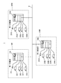
図1は、本発明の第1の実施の形態における会議システム全体の概要を示す図である。図1を参照して、第1の実施の形態における会議システム1は、ネットワーク2に接続された複合機(Multi Function Peripheral)(以下、「MFP」という)100,100A,100Bを含む。MFP100は、第1会議室300に設置され、第1会議室300に設置されたカメラ201および第1〜第4表示装置203,205,207,209と、接続される。MFP100Aは、第2会議室300Aに設置され、第2会議室300Aに設置されたカメラ201Aおよび第1〜第4表示装置203A,205A,207A,209Aと、接続される。MFP100Bは、第3会議室300Bに設置され、第3会議室300Bに設置されたカメラ201Bおよび第1〜第4表示装置203B,205B,207B,209Bと、接続される。
<First Embodiment>
FIG. 1 is a diagram showing an overview of the entire conference system according to the first embodiment of the present invention. Referring to FIG. 1, a
第1会議室300に設置されるMFP100は、カメラ201および第1〜第4表示装置203,205,207,209を制御する制御装置として機能し、第2会議室300Aに設置されるMFP100Aは、カメラ201Aおよび第1〜第4表示装置203A,205A,207A,209Aを制御する制御装置として機能し、第3会議室300Bに設置されるMFP100Bは、カメラ201Bおよび第1〜第4表示装置203B,205B,207B,209Bを制御する制御装置として機能する。
The
第1〜第4表示装置203,205,207,209,203A,205A,207A,209A,203B,205B,207B,209Bは、プロジェクタであり、画像をスクリーンに投影する。
The first to
MFP100,100A,100Bそれぞれのハードウエア構成および機能は同じなので、ここでは特に言及しない限りMFP100について説明する。また、説明のために、MFP100Aが備える部材および機能に、MFP100が備える部材および機能に付した番号に英字「A」を追加した符号を付し、MFP100Bが備える部材および機能に、MFP100が備える部材および機能に付した番号に英字「B」を追加した符号を付す。
Since
ネットワーク2は、ローカルエリアネットワーク(LAN)である。このため、MFP100,100A,100Bは、互いにデータを送受信することが可能である。なお、ネットワーク2は、LANに限らず、インターネット、ワイドエリアネットワーク(WAN)、公衆交換電話網等であってもよい。また、ネットワーク2は、有線であってもよく、無線であってもよい。
The
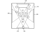
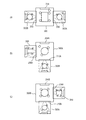
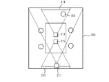
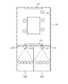
図2は、第1会議室におけるカメラ、第1〜第4表示装置の配置の一例を示す図である。図2は、第1会議室300を上から見た図である。図2を参照して、第1会議室300には、第1表示装置203が画像を投影する表示面となる第1スクリーン204と、第2表示装置205が画像を投影する表示面となる第2スクリーン206と、第3表示装置207が画像を投影する表示面となる第3スクリーン208と、第4表示装置209が画像を投影する表示面となる第4スクリーン210と、カメラ201とが配置される。第1〜第4表示装置203,205,207,209は、第1会議室300の天井に配置され、第1〜第4スクリーン204,206,208,210は、第1会議室300の4つの壁にそれぞれ配置される。第1スクリーン204と第4スクリーン210とは対面して配置され、第2スクリーン206と第3スクリーン208とは対面して配置される。第2スクリーン206は、第1会議室300内の参加者が第1スクリーン204に向かって右側に配置され、第3スクリーン208は、第1会議室300内の参加者が第1スクリーン204に向かって左側に配置される。カメラ201は、第4スクリーン210の上側に配置され、第1スクリーン204を撮像範囲に含む画角を有する。
FIG. 2 is a diagram illustrating an example of the arrangement of cameras and first to fourth display devices in the first conference room. FIG. 2 is a view of the
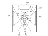
図3は、第2会議室におけるカメラ、第1〜第4表示装置の配置を示す図である。図3は、第2会議室300Aを上から見た図である。図3を参照して、第2会議室300Aには、第1表示装置203Aが画像を投影する表示面となる第1スクリーン204Aと、第2表示装置205Aが画像を投影する表示面となる第2スクリーン206Aと、第3表示装置207Aが画像を投影する表示面となる第3スクリーン208Aと、第4表示装置209Aが画像を投影する表示面となる第4スクリーン210Aと、カメラ201Aとが配置される。第1〜第4表示装置203A,205A,207A,209Aは、第2会議室300Aの天井に配置され、第1〜第4スクリーン204A,206A,208A,210Aは、第2会議室300Aの4つの壁にそれぞれ配置される。第1スクリーン204Aと第4スクリーン210Aとは対面して配置され、第2スクリーン206Aと第3スクリーン208Aとは対面して配置される。第2スクリーン206Aは、第2会議室300A内の人が第1スクリーン204Aに向かって右側に配置され、第3スクリーン208Aは、第2会議室300A内の人が第1スクリーン204Aに向かって左側に配置される。カメラ201Aは、第4スクリーン210Aの上側に配置され、第1スクリーン204Aを撮像範囲に含む画角を有する。
FIG. 3 is a diagram illustrating an arrangement of cameras and first to fourth display devices in the second conference room. FIG. 3 is a view of the
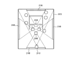
図4は、第3会議室におけるカメラ、第1〜第4表示装置の配置を示す図である。図4は、第3会議室300Bを上から見た図である。図4を参照して、第3会議室300Bには、第1表示装置203Bが画像を投影する表示面となる第1スクリーン204Bと、第2表示装置205Bが画像を投影する表示面となる第2スクリーン206Bと、第3表示装置207Bが画像を投影する表示面となる第3スクリーン208Bと、第4表示装置209Bが画像を投影する表示面となる第4スクリーン210Bと、カメラ201Bと、が配置される。第1〜第4表示装置203B,205B,307B,209Bは、第3会議室300Bの天井に配置され、第1〜第4スクリーン204B,206B,208B,210Bは、第3会議室300Bの4つの壁にそれぞれ配置される。第1スクリーン204Bと第4スクリーン210Bとは対面して配置され、第2スクリーン206Bと第3スクリーン208Bとは対面して配置される。第2スクリーン206Bは、第3会議室300B内の参加者が第1スクリーン204Bに向かって右側に配置され、第3スクリーン208Bは、第3会議室300B内の参加者が第1スクリーン204Bに向かって左側に配置される。カメラ201Bは、第4スクリーン210Bの上側に配置され、第1スクリーン204Bを撮像範囲に含む画角を有する。
FIG. 4 is a diagram illustrating an arrangement of cameras and first to fourth display devices in the third conference room. FIG. 4 is a view of the
本実施の形態における会議システム1は、MFP100,100A,100Bが第1〜第3仮想会議室をそれぞれ形成する。第1〜第3仮想会議室とは、第1〜第3会議室300,300A,300Bを用いて会議する場合に、MFP100,100A,100Bそれぞれで形成される仮想的な会議室である。例えば、MFP100が形成する第1仮想会議室において、第1会議室300に参加する参加者は、第1会議室300内の他の参加者を肉眼で確認し、第2会議室300Aおよび第3会議室300Bの様子を第2〜第4スクリーン206,208,210のいずれかに表示された画像で確認する。MFP100Aが形成する第2仮想会議室において、第2会議室300Aに参加する参加者は、第2会議室300A内の他の参加者を肉眼で確認し、第1会議室300および第3会議室300Bの様子を、第2〜第4スクリーン206A,208A,210Aのいずれかに表示された画像で確認する。MFP100Bが形成する第3仮想会議室において、第3会議室300Bに参加する参加者は、第3会議室300B内の他の参加者を肉眼で確認し、第1会議室300および第2会議室300Aの様子を、第2〜第4スクリーン206B,208B,210Bのいずれかに表示された画像で確認する。
In
MFP100,100A,100Bがそれぞれ形成する第1〜第3仮想会議室において、第1〜第3会議室300,300A,300Bそれぞれに参加する参加者の配列順はすべて同じになる。このため、第1〜第3仮想会議室における第1〜第3会議室300,300A,300Bの配列順番を予め定めておく必要がある。第1〜第3仮想会議室における第1〜第3会議室300,300A,300Bの配列順番は、MFP100,100A,100Bのいずれか1つで定められれば良い。ここでは、第1会議室300に設置されたMFP100において、第1〜第3会議室300,300A,300Bの配列順番が定められる場合を例に説明する。
In the first to third virtual conference rooms formed by the
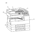
図5は、MFPの外観を示す斜視図である。図5を参照して、MFP100は、操作パネル9と、自動原稿搬送装置(ADF)10と、原稿読取部20と、画像形成部30と、給紙部40と、を含む。
FIG. 5 is a perspective view showing the appearance of the MFP. Referring to FIG. 5,
ADF10は、原稿給紙トレイ11上にセットされた複数枚の原稿を1枚ずつ自動的に原稿読取部20のプラテンガラス上に設定された所定の原稿読取位置まで搬送し、原稿読取部20により原稿画像が読み取られた原稿を原稿排紙トレイ上に排出する。原稿読取部20は、原稿読取位置に搬送されてきた原稿に光を照射する光源と、原稿で反射した光を受光する光電変換素子とを含み、原稿のサイズに応じた原稿画像を走査する。光電変換素子は、受光した光を電気信号である画像データに変換して、メモリに記憶する、または画像形成部30に出力する。
The
画像形成部30は、周知の電子写真方式により画像を形成するものであって、原稿読取部20から入力される画像データにシェーディング補正などの各種のデータ処理を施し、データ処理後の画像データに基づいて、給紙部40により搬送される用紙に画像を形成する。給紙部40は、給紙トレイに収納された用紙を画像形成部30に搬送する。
The
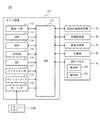
図6は、MFPのハードウエア構成の一例を示すブロック図である。図6を参照して、MFP100は、メイン回路101と、ADF10と、原稿読取部20と、画像形成部30と、給紙部40と、ユーザインターフェースとしての操作パネル9と、を含む。
FIG. 6 is a block diagram illustrating an example of a hardware configuration of the MFP. Referring to FIG. 6,
メイン回路101は、CPU111と、通信インターフェース(I/F)部112と、ROM(Read Only Memory)113と、RAM(Random Access Memory)114と、EEPROM(Electronically Erasable and Programmable ROM)115と、大容量記憶装置としてのハードディスクドライブ(HDD)116と、ファクシミリ部117と、ネットワークI/F118と、フラッシュメモリ119Aが装着されるカードI/F119とを含む。CPU111は、ADF10、原稿読取部20、画像形成部30、給紙部40および操作パネル9と接続され、MFP100の全体を制御する。
The
ROM113は、CPU111が実行するプログラム、およびそのプログラムを実行するために必要なデータを記憶する。RAM114は、CPU111がプログラムを実行する際の作業領域として用いられる。
The
通信I/F部112は、カメラ201、第1〜第4表示装置203,205,207,209が接続されるインターフェースである。なお、通信I/F部112と、カメラ201、第1〜第4表示装置203,205,207,209との接続形態は、有線であっても無線であってもよい。
The communication I /
ファクシミリ部117は、公衆交換電話網(PSTN)に接続され、PSTNにファクシミリデータを送信する、またはPSTNからファクシミリデータを受信する。ファクシミリ部117は、受信したファクシミリデータを、HDD116に記憶する、または画像形成部30に出力する。画像形成部30は、ファクシミリ部117により受信されたファクシミリデータを用紙に印刷する。また、ファクシミリ部117は、HDD116に記憶されたデータをファクシミリデータに変換して、PSTNに接続されたファクシミリ装置に送信する。
The
ネットワークI/F118は、MFP100をネットワーク2に接続するためのインターフェースである。カードI/F119は、フラッシュメモリ119Aが装着される。CPU111は、カードI/F119を介してフラッシュメモリ119Aにアクセス可能であり、フラッシュメモリ119Aに記憶されたプログラムをRAM114にロードして実行可能である。なお、CPU111が実行するプログラムは、フラッシュメモリ119Aに記憶されたプログラムに限られず、他の記憶媒体に記憶されたプログラムでもよく、HDD116に記憶されたプログラムであってもよく、さらに、ネットワークI/F118を介してネットワーク2に接続された他のコンピュータによりHDD116に書き込みされたプログラムであってもよい。
A network I /
なお、プログラムを記憶する記憶媒体としては、フラッシュメモリ119Aに限られず、光ディスク(MO(Magnetic Optical Disc)/MD(Mini Disc)/DVD(Digital Versatile Disc))、ICカード、光カード、マスクROM、EPROM(Erasable Programmable ROM)、EEPROM(Electrically Erasable and Programmable ROM)などの半導体メモリでもよい。
The storage medium for storing the program is not limited to the
ここでいうプログラムは、CPU111が直接実行可能なプログラムだけでなく、ソースプログラム、圧縮処理されたプログラム、暗号化されたプログラム等を含む。
The program here includes not only a program directly executable by the
操作パネル9は、MFP100の上面に設けられ、表示部103と操作部105とを含む。操作パネル9は、表示部103と、操作部105とを含む。表示部103は、液晶表示装置、有機ELD(Electroluminescence Display)等の表示装置であり、ユーザに対する指示メニューや取得した表示データに関する情報等を表示する。
操作部105は、ユーザの操作を受け付け、受け付けられた操作をCPU111に出力する。操作部105は、表示部103の上に重畳して配置されたタッチパネルを含む。タッチパネルは、透明な部材からなり、表示部103に重畳して配置される。操作部105は、ユーザがタッチパネルを指で触れると、触れられた位置を指示位置として検出し、CPU111に出力する。
The
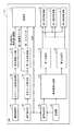
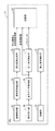
図7は、MFPが備えるCPUの機能の概要の一例を示すブロック図である。図7に示すCPU111の機能は、CPU111がROM113、EEPROM115、HDD116またはフラッシュメモリ119Aに記憶された表示制御プログラムを実行することにより実現される。
FIG. 7 is a block diagram illustrating an example of an overview of the functions of the CPU provided in the MFP. The functions of the
図7を参照して、CPU111は、カメラ201を制御する撮像制御部51と、撮像制御部51がカメラ201から受信する動画像からスクリーンの領域を抽出するスクリーン領域抽出部53と、動画像からスクリーン領域を除いた部分画像を生成する部分画像生成部55と、MFP100A、100Bにデータを送信する送信部57と、ユーザによる操作を受け付ける操作受付部59と、表示データを取得する表示データ取得部61と、第1表示装置203を制御する第1表示制御部71と、第1〜第3会議室300Bの配列を決定する配列決定部65と、MFP100A、100Bからデータを受信する受信部63と、第2〜第4表示装置205,207,208に表示する画像を決定する表示画像決定部67と、第1合成部69と、第2合成部70と、第2表示装置203を制御する第2表示制御部72と、第3表示装置207を制御する第3表示制御部73と、第4表示装置209を制御する第4表示制御部74と、を含む。
Referring to FIG. 7, the
操作受付部59は、ユーザが操作部105に入力する操作を受け付ける。操作受付部59は、ユーザがファイル一覧を表示する指示を操作部105に入力すると、EEPROM115に予め記憶されたデータを識別するためのファイル名を含むファイル一覧を表示する。ファイル一覧は、EEPROM115に複数の発表用データが記憶されている場合、複数の発表用データをそれぞれ識別するための複数のファイル名を含む。操作受付部59は、ユーザがファイル一覧に含まれるファイル名を選択する操作を操作部105に入力すると、選択指示を送信部57および表示データ取得部61に出力する。選択指示は、ユーザにより選択されたファイル名を含む。ここでは、EEPROM115に記憶された第1発表用データがユーザにより選択された場合を例に説明する。
The
さらに、操作受付部59は、ユーザが、操作部105に入力する第1〜第3会議室300,300A,300Bの配列順番を受け付け、受け付けられた配列順番を配列決定部65および送信部57に出力する。ここでは、配列順番を、左から順に第3会議室300B、第1会議室300、第2会議室300Aとする場合を例に説明する。
Further, the
表示データ取得部61は、操作受付部59から選択指示が入力されると、入力された選択指示に含まれるファイル名で特定される第1発表用データをEEPROM115から読み出し、読出された第1発表用データを第1表示制御部71および送信部57に出力する。第1表示制御部71は、表示データ取得部61から入力される第1発表用データを、第1表示装置203に出力し、第1表示装置203に第1発表用データの画像を表示させる。また、第1表示制御部71は、第1表示制御部71が第1発表用データを表示する際に用いた第1パラメータを、送信部57に出力する。第1パラメータは、例えば、第1表示装置203の色プロファイルを含む。
When the selection instruction is input from the
撮像制御部51は、カメラ201を制御し、カメラ201が撮像して出力する動画像を取得する。カメラ201は、上述したように、その画角が第1スクリーン204と第1会議室300の参加者を被写体として含む撮像範囲となるように定められている。このため、カメラ201が出力する動画像は、第1スクリーン204が表された画像を含む。撮像制御部51は、カメラ201から取得される動画像をリアルタイムでスクリーン領域抽出部53に出力する。
The
スクリーン領域抽出部53は、撮像制御部51から入力される動画像から第1スクリーン204が表されたスクリーン領域を抽出する。具体的には、動画像に含まれるフレームごとに、第1スクリーン204が表されたスクリーン領域を抽出する。例えば、第1スクリーン204の輪郭は矩形なのでフレームを微分したエッジ画像の中央付近に存在する矩形のエッジで囲まれた領域をスクリーン領域として抽出する。スクリーン領域抽出部53は、撮像制御部51から入力される動画像と、その動画中の第1スクリーン204が表されたスクリーン領域の位置を示す第1表示領域情報とを、部分画像生成部55に出力する。また、スクリーン領域抽出部53は、撮像制御部51から入力される動画像から、レーザポインタが照射された部分を検出するようにしてもよい。この場合、第1表示領域情報は、検出されたレーザポインタが照射された部分のフレーム中の位置を指示位置として含む。
The screen
部分画像生成部55は、スクリーン領域抽出部53から動画像と、第1表示領域情報とが入力され、第1表示領域情報に基づいて動画像からスクリーン領域を除くことによって、第1部分画像を生成する。具体的には、動画像に含まれるフレームの第1表示領域情報で特定される領域の画素の値を「0」にしたフレームに変換することにより、第1部分画像を生成する。部分画像生成部55は、生成された第1部分画像と第1表示領域情報とを送信部57に出力する。
The partial
送信部57は、表示データ取得部61から入力される第1発表用データと、第1表示制御部71から入力される第1パラメータとの組を、ネットワークI/F118を介して、MFP100A,100Bそれぞれに送信する。また、送信部57は、部分画像生成部55から入力される第1部分画像と第1表示領域情報とを、ネットワークI/F118を介して、MFP100A,100Bそれぞれに送信する。第1部分画像は、例えば、ストリーミング配信の技術を用いて、リアルタイムで送信する。さらに、送信部57は、操作受付部59から配列順番が入力されると、入力された配列順番を、ネットワークI/F118を介して、MFP100A,100Bそれぞれに送信する。
ここまで説明したMFP100が備えるCPU111の機能に対応するMFP100A,100Bそれぞれが備えるCPU111A,111Bの機能それぞれについて説明する。第2仮想会議室を形成するMFP100Aが備えるCPU111Aにおいて、表示データ取得部61Aは、ユーザがファイル名を選択すると、選択されたファイル名で特定される第2発表用データをEEPROM115Aから読み出し、読出された第2発表用データを第1表示制御部71Aおよび送信部57Aに出力する。第1表示制御部71Aは、第2発表用データを、第1表示装置203Aに出力し、第1表示装置203Aに第2発表用データの画像を表示させる。また、第1表示制御部71Aは、第1表示制御部71Aが第2発表用データを表示する際に用いた第2パラメータを、送信部57Aに出力する。第2パラメータは、第1表示装置203Aの色プロファイルを含む。
The functions of
撮像制御部51Aは、カメラ201Aを制御し、カメラ201Aが撮像して出力する動画像を取得する。カメラ201Aは、上述したように、その画角が第1スクリーン204Aと第2会議室300Aの参加者を被写体として含む撮像範囲となるように定められている。このため、カメラ201Aが出力する動画像は、第1スクリーン204Aが表された画像を含む。撮像制御部51Aは、カメラ201Aから取得される動画像をリアルタイムでスクリーン領域抽出部53Aに出力する。
The imaging control unit 51A controls the
スクリーン領域抽出部53Aは、撮像制御部51Aから入力される動画像から第1スクリーン204Aが表されたスクリーン領域を抽出し、撮像制御部51Aから入力される動画像と、その動画中の第1スクリーン204Aが表されたスクリーン領域の位置を示す第2表示領域情報とを、部分画像生成部55Aに出力する。また、スクリーン領域抽出部53Aは、撮像制御部51Aから入力される動画像から、レーザポインタが照射された部分を検出するようにしてもよい。この場合、第2表示領域情報は、検出されたレーザポインタが照射された部分のフレーム中の位置を指示位置として含む。
The screen area extraction unit 53A extracts the screen area in which the
部分画像生成部55Aは、スクリーン領域抽出部53Aから動画像と、第2表示領域情報とが入力され、第2表示領域情報に基づいて動画像からスクリーン領域を除くことによって、第2部分画像を生成する。部分画像生成部55Aは、生成された第2部分画像と第2表示領域情報とを送信部57に出力する。
The partial image generation unit 55A receives the moving image and the second display region information from the screen region extraction unit 53A, and removes the screen region from the moving image based on the second display region information, thereby obtaining the second partial image. Generate. The partial image generation unit 55A outputs the generated second partial image and second display area information to the
送信部57Aは、表示データ取得部61Aから入力される第2発表用データと、第1表示制御部71Aから入力される第2パラメータとの組を、ネットワークI/F118Aを介して、MFP100,100Bそれぞれに送信する。また、送信部57Aは、部分画像生成部55Aから入力される第2部分画像と第2表示領域情報とを、ネットワークI/F118Aを介して、MFP100,100Bそれぞれに送信する。第2部分画像は、例えば、ストリーミング配信の技術を用いて、リアルタイムで送信する。
The transmission unit 57A transmits a set of the second presentation data input from the display data acquisition unit 61A and the second parameter input from the first display control unit 71A to the
第3仮想会議室を形成するMFP100Bが備えるCPU111Bにおいて、表示データ取得部61Bは、ユーザがファイル名を選択すると、選択されたファイル名で特定される第3発表用データをEEPROM115Bから読み出し、読出された第3発表用データを第1表示制御部71Bおよび送信部57Bに出力する。第1表示制御部71Bは、第3発表用データを、第1表示装置203Bに出力し、第1表示装置203Bに第3発表用データの画像を表示させる。また、第1表示制御部71Bは、第1表示制御部71Bが第3発表用データを表示する際に用いた第3パラメータを、送信部57Bに出力する。第3パラメータは、第1表示装置203Bの色プロファイルを含む。
In CPU 111B provided in
撮像制御部51Bは、カメラ201Bを制御し、カメラ201Bが撮像して出力する動画像を取得する。カメラ201Bは、上述したように、その画角が第1スクリーン204Bと第3会議室300Bの参加者を被写体として含む撮像範囲となるように定められている。このため、カメラ201Bが出力する動画像は、第1スクリーン204Bが表された画像を含む。撮像制御部51Bは、カメラ201Bから取得される動画像をリアルタイムでスクリーン領域抽出部53Bに出力する。
The imaging control unit 51B controls the
スクリーン領域抽出部53Bは、撮像制御部51Bから入力される動画像から第1スクリーン204Bが表されたスクリーン領域を抽出し、撮像制御部51Bから入力される動画像と、その動画中の第1スクリーン204Bが表されたスクリーン領域の位置を示す第3表示領域情報とを、部分画像生成部55Bに出力する。また、スクリーン領域抽出部53Bは、撮像制御部51Bから入力される動画像から、レーザポインタが照射された部分を検出するようにしてもよい。この場合、第3表示領域情報は、検出されたレーザポインタが照射された部分のフレーム中の位置を指示位置として含む。
The screen area extraction unit 53B extracts the screen area where the
部分画像生成部55Bは、スクリーン領域抽出部53Bから動画像と、第3表示領域情報とが入力され、第3表示領域情報に基づいて動画像からスクリーン領域を除くことによって、第3部分画像を生成する。部分画像生成部55Bは、生成された第3部分画像と第3表示領域情報とを送信部57に出力する。
The partial image generation unit 55B receives the moving image and the third display region information from the screen region extraction unit 53B, and removes the screen region from the moving image based on the third display region information. Generate. The partial image generation unit 55B outputs the generated third partial image and third display area information to the
送信部57Bは、表示データ取得部61Bから入力される第3発表用データと、第1表示制御部71Bから入力される第3パラメータとの組を、ネットワークI/F118Bを介して、MFP100,100Aそれぞれに送信する。また、送信部57Bは、部分画像生成部55Bから入力される第3部分画像と第3表示領域情報とを、ネットワークI/F118Bを介して、MFP100,100Aそれぞれに送信する。第3部分画像は、例えば、ストリーミング配信の技術を用いて、リアルタイムで送信する。
The transmission unit 57B transmits a set of the third presentation data input from the display data acquisition unit 61B and the third parameter input from the first display control unit 71B to the
MFP100が備えるCPU111の機能の説明に戻る。受信部63は、ネットワークI/F118を制御して、MFP100Aが送信する第2発表用データと第2パラメータとの組、第2部分画像と第2表示領域情報の組とを受信する。また、受信部63は、ネットワークI/F118を制御して、MFP100Bが送信する第3発表用データと第3パラメータとの組、第3部分画像と第3表示領域情報との組を受信する。受信部63は、第2発表用データと第2パラメータとの組、第2部分画像と第2表示領域情報との組、第3発表用データと第3パラメータとの組、第3部分画像と第3表示領域情報との組を、表示画像決定部67に出力する。
Returning to the description of the functions of the
配列決定部65は、第1仮想会議室における第1〜第3会議室300,300A,300Bの配列順番を決定する。具体的には、配列決定部65は、操作受付部59から配列順番が入力される場合、入力された配列順番を、表示画像決定部67に出力し、受信部63から配列順番が入力される場合、受信部63から入力される配列順番を表示画像決定部67に出力する。ここでは、操作受付部59から配列順番が入力されるので、配列決定部65は、操作受付部59から入力された配列順番を、表示画像決定部67に出力する。なお、MFP100Aにおいては、MFP100から配列順番を受信するので、配列決定部65Aは、受信部63Aから入力される配列順番を表示画像決定部67Aに出力する。同様に、MFP100Bが備えるCPU100Bが有する配列決定部65Bは、受信部63Bから入力される配列順番を表示画像決定部67Bに出力する。
The
表示画像決定部67は、配列決定部65から配列順番が入力され、受信部63から第2発表用データと第2パラメータとの組、第2部分画像と第2表示領域情報との組、第3発表用データと第3パラメータとの組、第3部分画像と第3表示領域情報との組が入力される。表示画像決定部67は、配列決定部65から入力される配列順番に基づいて、第2部分画像および第3部分画像それぞれを第2〜第4表示装置205,207,209のいずれに表示させるかを決定する。
The display
表示画像決定部67は、第1会議室300で表示される第1表示データが表示される第1スクリーン204を基準にして、第2部分画像および第3部分画像それぞれを第2〜第4表示装置205,207,209のいずれに表示させるかを決定する。ここでは、配列順番を、左から順に第3会議室300B、第1会議室300、第2会議室300Aの順にしている。このため、表示画像決定部67は、第1スクリーン204の左側に配置された第3スクリーン208に第3会議室300Bを撮像した画像を含む第3部分画像が表示されるように、第3部分画像を表示する表示装置を第3表示装置207に決定し、第1スクリーン204の右側に配置された第2スクリーン206に第2会議室を撮像した画像を含む第2部分画像が表示されるように、第2部分画像を表示させる表示装置を第2表示装置205に決定する。表示画像決定部67は、第1合成部69に、第2部分画像と第2表示領域情報との組、第2発表用データと第2パラメータとの組、および第2表示装置205を識別するための装置識別情報とを出力する。また、表示画像決定部67は、第2合成部70に、第3部分画像と第3表示領域情報との組、第3発表用データと第3パラメータとの組、および第3表示装置207を識別するための装置識別情報とを出力する。
The display
第1合成部69は、第2部分画像の第2表示領域情報で特定される領域に、第2発表用データを合成した第1合成画像を生成する。第1合成部69は、第2表示領域情報が指示位置を含む場合、第1合成画像の指示位置で特定される部分に、レーザポインタが照射されたことを示す画像を合成する。第1合成部69は、入力される装置識別情報で特定される第2表示装置205を制御する第2表示制御部72に、生成された第1合成画像を出力する。第2部分画像の第2表示領域情報で特定される領域に、第2発表用データを合成するので、第1合成画像中で第2発表画用データを可能な限り鮮明な画像とすることができる。
The 1st synthetic |
第2合成部70は、第3部分画像の第3表示領域情報で特定される領域に、第3発表用データを合成した第2合成画像を生成する。第2合成部70は、第3表示領域情報が指示位置を含む場合、第2合成画像の指示位置で特定される部分に、レーザポインタが照射されたことを示す画像を合成する。第2合成部70は、入力される装置識別情報で特定される第3表示装置207を制御する第3表示制御部73に、生成された第2合成画像を出力する。第3部分画像の第3表示領域情報で特定される領域に、第3発表用データを合成するので、第2合成画像中で第3発表画用データを可能な限り鮮明な画像とすることができる。
The
第2表示制御部72は、第2表示装置205を制御し、第2表示装置205に画像を表示させる。第3表示制御部73は、第3表示装置207を制御し、第3表示装置207に画像を表示させる。第4表示制御部74は、第4表示装置209を制御し、第4表示装置209に画像を表示させる。ここでは、第2表示制御部72に、第1合成画像が入力され、第3表示制御部73に第2合成画像が入力される。第2表示制御部72は、第2表示装置205に第2会議室300Aを撮像した画像を含む第1合成画像を投影させるので、第2スクリーン206に第2会議室300Aを撮像した画像が表示される。第3表示制御部73は、第3表示装置207に第3会議室300Bを撮像した画像を含む第2合成画像を投影させるので、第3スクリーン208に第3会議室300Bを撮像した画像が表示される。第1会議室300は、第1スクリーン204の左側に第3スクリーン208が配置され、第1スクリーンの右側に第2スクリーン206が配置されているので、第1会議室300の参加者は、第1スクリーン204の左側に第3会議室300Bを撮像した画像を見ることができ、第1スクリーン204の右側に第2会議室300Aを撮像した画像を見ることができる。
The second
上記MFP100が備えるCPU111の機能に対応するMFP100A,100Bそれぞれが備えるCPU111A,111Bの機能それぞれについてさらに説明する。第2仮想会議室を形成するMFP100Aが備えるCPU111Aが有する表示画像決定部67Aは、第1スクリーン204Aに第2会議室300Aで表示される第2表示用データが表示されるので、第1スクリーンの左側に配置された第3スクリーン208Aに第1会議室300を撮像した画像を含む第1部分画像が表示されるように、第1部分画像を表示する表示装置を第3表示装置207Aに決定し、第4スクリーン210Aに第3会議室300Bを撮像した画像を含む第3部分画像が表示されるように、第3部分画像を表示する表示装置を第4表示装置209Aに決定する。
Each of the functions of
MFP100Aが備えるCPU111Aが有する表示画像決定部67Aは、第1合成部69Aに、第1部分画像と第1表示領域情報との組、第1発表用データと第1パラメータとの組、および第3表示装置207Aを識別するための装置識別情報とを出力する。また、表示画像決定部67Aは、第2合成部70Aに、第3部分画像と第3表示領域情報との組、第3発表用データと第3パラメータとの組、および第4表示装置209Aを識別するための装置識別情報とを出力する。
The display image determination unit 67A of the
第1合成部69Aは、第1部分画像の第1表示領域情報で特定される領域に、第1発表用データを合成した第1合成画像を生成する。第1合成部69Aは、入力される装置識別情報で特定される第3表示装置207Aを制御する第3表示制御部73Aに、生成された第1合成画像を出力する。第2合成部70Aは、第3部分画像の第3表示領域情報で特定される領域に、第3発表用データを合成した第2合成画像を生成する。第2合成部70Aは、入力される装置識別情報で特定される第4表示装置209Aを制御する第4表示制御部74Aに、生成された第2合成画像を出力する。
69 A of 1st synthetic | combination parts produce | generate the 1st synthesized image which synthesize | combined the data for 1st presentation in the area | region specified with the 1st display area information of a 1st partial image. The first combining unit 69A outputs the generated first combined image to the third display control unit 73A that controls the
さらに、第3表示制御部73Aは、第3表示装置207Aに第1会議室300を撮像した画像を含む第1合成画像を投影させるので、第3スクリーン208Aに第1会議室300を撮像した画像が表示される。第4表示制御部74Aは、第4表示装置207Aに第3会議室300Bを撮像した画像を含む第2合成画像を投影させるので、第4スクリーン210Aに第3会議室300Bを撮像した画像が表示される。第2会議室300Aは、第1スクリーン204Aの左側に第3スクリーン208Aが配置され、さらにその左側に第4スクリーン210Aが配置されているので、第2会議室300Aの参加者は、第1スクリーン204Aの左側に第1会議室300を撮像した画像を見ることができ、さらにその左側に第3会議室300Bを撮像した画像を見ることができる。
Further, since the third display control unit 73A projects a first composite image including an image obtained by imaging the
また、第3仮想会議室を形成するMFP100Bが備えるCPU111Bが有する表示画像決定部67Bは、第1スクリーン204Bに第3表示用データが表示されるので、第1スクリーン204Bの左側に配置された第2スクリーン206Bに第1会議室を撮像した画像が表示されるように、第1部分画像を表示する表示装置を第2表示装置205Bに決定し、第4スクリーン210Bに第2会議室を撮像した画像が表示されるように、第2部分画像を表示する表示装置を第4表示装置209Bに決定する。MFP100Bが備えるCPU111Bが有する表示画像決定部67Bは、第1合成部69Bに、第1部分画像と第1表示領域情報との組、第1発表用データと第1パラメータとの組、および第2表示装置205Bを識別するための装置識別情報とを出力する。また、表示画像決定部67Bは、第2合成部70Bに、第2部分画像と第2表示領域情報との組、第2発表用データと第2パラメータとの組、および第4表示装置209Bを識別するための装置識別情報とを出力する。
In addition, the display image determination unit 67B of the CPU 111B included in the
第1合成部69Bは、第1部分画像の第1表示領域情報で特定される領域に、第1発表用データを合成した第1合成画像を生成する。第1合成部69Bは、入力される装置識別情報で特定される第2表示装置205Bを制御する第2表示制御部72Bに、生成された第1合成画像を出力する。第2合成部70Bは、第2部分画像の第2表示領域情報で特定される領域に、第2発表用データを合成した第2合成画像を生成する。第2合成部70Bは、入力される装置識別情報に基づいて、第4表示装置209Bを制御する第4表示制御部74Bに、生成された第2合成画像を出力する。
The first synthesizing unit 69B generates a first synthesized image obtained by synthesizing the first presentation data in the area specified by the first display area information of the first partial image. The first combining unit 69B outputs the generated first combined image to the second display control unit 72B that controls the
第2表示制御部72Bは、第2表示装置205Bに第1会議室300を撮像した画像を含む第1合成画像を投影させるので、第2スクリーン206Bに第1会議室300を撮像した画像が表示される。第4表示制御部74Bは、第4表示装置209Bに第2会議室300Aを撮像した画像を含む第2合成画像を投影させるので、第4スクリーン210Bに第2会議室300Aを撮像した画像が表示される。第3会議室300Bは、第1スクリーン204Bの右側に第2スクリーン206Bが配置され、さらにその右側に第4スクリーン210Bが配置されているので、第3会議室300Bの参加者は、第1スクリーン204Bの右側に第1会議室300を撮像した画像を見ることができ、さらにその右側に第2会議室300Aを撮像した画像を見ることができる。
Since the second display control unit 72B projects the first composite image including the image obtained by imaging the
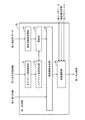
図8は、第1合成部の詳細な機能の一例を示す図である。図8においては、第1合成部に、第2部分画像、第2表示領域情報、第2発表用データおよび第2パラメータが入力される場合を例に示している。図8を参照して、第1合成部69は、スクリーン領域検知部81と、スクリーン係数決定部83と、発表用画像取得部85と、変形部87と、発表画像合成部89と、画像調整部90と、を含む。
FIG. 8 is a diagram illustrating an example of detailed functions of the first combining unit. FIG. 8 shows an example in which the second partial image, the second display area information, the second presentation data, and the second parameter are input to the first synthesis unit. Referring to FIG. 8, the
スクリーン領域検知部81は、第2表示領域情報が入力される。スクリーン領域検知部81は、第2表示領域情報により特定される第2部分画像中のスクリーン領域を検知する。スクリーン領域検知部81は、検知した第2部分画像中のスクリーン領域を、スクリーン係数決定部83に出力する。スクリーン係数決定部83は、スクリーン領域検知部81から入力されるスクリーン領域が、画面全体に占める割合を算出し、算出された割合を示すスクリーン係数を決定する。スクリーン係数決定部83は、決定されたらスクリーン係数を、変形部87に出力する。
The screen
発表用画像取得部85は、第2発表用データが入力される。発表用画像取得部85は、第2発表用データに基づいて発表用画像を取得し、取得された発表用画像を変形部87に出力する。発表用画像は、例えば、第2会議室300Aにおいて表示されている画像と同じ画像であり、第2発表用データが複数ページで構成される場合には、複数ページのうちから第2会議室300Aのユーザにより選ばれたページの画像である。
The presentation
変形部87は、スクリーン係数に基づいて、発表用画像取得部85から入力される発表用画像を変形し、変形後の発表用画像を発表画像合成部89に出力する。具体的には、発表用画像を、スクリーン係数に基づいて縮小する。なお、変形部87は、スクリーン係数が所定の値以下の場合、発表用画像取得部85から入力される発表用画像を縮小することなく、発表用画像を発表画像合成部89に出力する。
The
発表画像合成部89は、第2部分画像の第2表示領域情報により特定される領域に、変形部87から入力される発表用画像を合成することにより、第1合成画像を生成する。なお、発表画像合成部89は、変形部87から入力される発表用画像のサイズが縮小されていない場合、第2部分画像に発表用画像を合成することなく、発表用画像のみを画像調整部90に出力する。これにより、第2部分画像中に占めるスクリーンの領域の割合が所定の値よりも小さい場合には、発表用画像のみが表示される。このため、発表用画像の内容を読み取れるサイズで表示することができる。
The presentation
画像調整部90は、表示画像決定部67から装置識別情報、ここでは、第2表示装置205Bの装置識別情報と、第2パラメータとが入力される。画像調整部90は、表示画像決定部67から入力される装置識別情報で特定される第2表示装置205Bに対して予め定められた色プロファイルを読み出し、表示画像決定部67から入力される第2パラメータと、読み出された第2表示装置205Bの色プロファイルとに基づいて、色の補正量を決定する。そして、画像調整部90は、決定された補正量で第1合成画像の発表用画像の部分を、他の部分と独立して補正する。このため、第2会議室300Aで表示されている第2発表用データの色温度に近い色温度の画像を第2表示装置205Bに表示させることができる。
The
第2合成部70は、第1合成部69と、取り扱うデータが異なるのみで、機能は同じである。したがってここでは説明を繰り返さない。
The
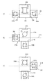
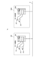
図9(A)は、第1仮想会議室を模式的に示す図である。図9(A)は、第1仮想会議室を上から見た図である。図9(A)を参照して、第1仮想会議室は、第1会議室300の参加者に知覚される仮想的な空間である。上述したように、第1会議室300に配置された第2スクリーン206に第2会議室300Aを撮像した画像が表示され、第1会議室300に配置された第3スクリーン208に第3会議室300Bを撮像した画像が表示される。このため、第1会議室300の参加者は、第1スクリーン204に向かって左側に第3会議室300B300Bの様子を確認でき、第1スクリーン204に向かって右側に第2会議室300Aの様子を確認できる。したがって、第1会議室300の参加者は、第1スクリーン204に向かって左側に第3会議室300Bの空間が配置され、第1スクリーン204に向かって右側に第2会議室300Aの空間が配置されているように知覚する。
FIG. 9A is a diagram schematically showing the first virtual conference room. FIG. 9A is a view of the first virtual conference room as viewed from above. With reference to FIG. 9A, the first virtual conference room is a virtual space that is perceived by the participants of the
図9(B)は、第2仮想会議室を模式的に示す図である。図9(B)は、第2仮想会議室を上から見た図である。図9(B)を参照して、第2仮想会議室は、第2会議室300Aの参加者に知覚される仮想的な空間である。上述したように、第2会議室300Aに配置された第3スクリーン208に第1会議室300を撮像した画像が表示され、第2会議室300Aに配置された第4スクリーン210Aに第3会議室300Bを撮像した画像が表示される。このため、第2会議室300Aの参加者は、第1スクリーン204Aに向かって左側に第1会議室300の様子を確認でき、さらに、その左側に第3会議室300Bの様子を確認できる。したがって、第2会議室300Aの参加者は、第1スクリーン204Aに向かって左側に第1会議室300の空間が配置され、さらにその左側に第3会議室300Bの空間が配置されているように知覚する。
FIG. 9B is a diagram schematically showing the second virtual conference room. FIG. 9B is a view of the second virtual conference room as viewed from above. Referring to FIG. 9B, the second virtual conference room is a virtual space that is perceived by the participants in the
図9(C)は、第3仮想会議室を模式的に示す図である。図9(C)は、第3仮想会議室を上から見た図である。図9(C)を参照して、第3仮想会議室は、第3会議室300Bの参加者に知覚される仮想的な空間である。上述したように、第3会議室300Bに配置された第2スクリーン206に第1会議室300を撮像した画像が表示され、第3会議室300Bに配置された第4スクリーン210Bに第2会議室300Aを撮像した画像が表示される。このため、第3会議室300Bの参加者は、第1スクリーン204Bに向かって右側に第1会議室300の様子を確認でき、さらに、その右側に第2会議室300Aの様子を確認できる。したがって、第3会議室300Bの参加者は、第1スクリーン204Bに向かって右側に第1会議室300の空間が配置され、さらにその右側に第2会議室300Aの空間が配置されているように知覚する。
FIG. 9C is a diagram schematically showing the third virtual conference room. FIG. 9C is a view of the third virtual conference room as viewed from above. With reference to FIG. 9C, the third virtual conference room is a virtual space perceived by the participants of the
第1〜第3仮想会議室のいずれにおいても第1〜第3会議室300,300A,300Bが配置される順番は同じである。このため、第1〜第3会議室300,300A,300Bの参加者のすべてが、あたかも同じ空間にいるような仮想空間を構成することができる。
In any of the first to third virtual conference rooms, the order in which the first to
次に、参加者の視線を合せた仮想会議室について説明する。ここでの視線は、第1〜第3会議室300,300A,300Bそれぞれの参加者の視線であり、第1〜第3会議室300,300A,300Bそれぞれで表示されている発表用データに向く視線をいう。この参加者の視線を合せた仮想会議室を実現するために、第1〜第3会議室それぞれにおいて、第2および第3スクリーン206,208,206A,208A,206B,208Bは、その中心の法線が、参加者よりもカメラ201,201A,201B側に位置する。
Next, a virtual conference room that matches the gaze of the participant will be described. The line of sight here is the line of sight of the participants in each of the first to
図10(A)は、参加者の視線を合せた第1仮想会議室を模式的に示す図である。図10(A)を参照して、第2および第3スクリーン206,208の中心の法線が、参加者よりもカメラ201側に位置する。図10(B)は、参加者の視線を合せた第2仮想会議室を模式的に示す図である。図10(B)を参照して、第2および第3スクリーン206A,208Aの中心の法線が、参加者よりもカメラ201A側に位置する。図10(C)は、参加者の視線を合せた第3仮想会議室を模式的に示す図である。図10(C)を参照して、第2および第3スクリーン206B,208Bの中心の法線が、参加者よりもカメラ201B側に位置する。
FIG. 10A is a diagram schematically illustrating the first virtual conference room in which the gazes of the participants are matched. With reference to FIG. 10 (A), the normal line of the center of the 2nd and 3rd screen 206,208 is located in the
参加者の視線を合せた第1〜第3仮想会議室においては、第1会議室300の参加者の視線が第1〜第4スクリーン204,206,208,210のいずれに向かっているのかを、第2会議室300Aの参加者が第3スクリーン206Aに映る第1会議室300の参加者の画像から判断でき、第3会議室300Bの参加者が第2スクリーン206Bに映る第1会議室300の参加者の画像から判断できる。
In the first to third virtual conference rooms in which the gazes of the participants are combined, it is determined which of the first to
第2会議室300Aの参加者の視線が第1〜第4スクリーン204A,206A,208A,210Aのいずれに向かっているのかを、第1会議室300の参加者が第2スクリーン206に映る第2会議室300Aの参加者の画像から判断でき、第3会議室300Bの参加者が第4スクリーン210Bに映る第2会議室300Aの参加者の画像から判断できる。
A participant in the
第3会議室300Bの参加者の視線が第1〜第4スクリーン204B,206B,208B,210Bのいずれに向かっているのかを、第1会議室300の参加者が第3スクリーン208に映る第3会議室300Bの参加者の画像から判断でき、第2会議室300Aの参加者が第4スクリーン210Aに映る第3会議室300Bの参加者の画像から判断できる。
The
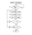
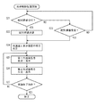
図11は、発表用データ送信処理の流れの一例を示すフローチャートである。発表用データ送信処理は、MFP100が備えるCPU111がROM113、EEPROM115、HDD116またはフラッシュメモリ119Aに記憶された表示制御プログラムを実行することにより、CPU111により実行される処理である。
FIG. 11 is a flowchart illustrating an exemplary flow of a presentation data transmission process. The presentation data transmission process is a process executed by the
図11を参照して、CPU111は、データの指定を受け付けたか否かを判断する(ステップS01)。ユーザが、操作部105を操作することにより、HDD116に記憶されたデータのうちから1つを指定すると、データの指定を受け付ける。データの指定を受け付けるまで待機状態となり(ステップS01でNO)、データの指定を受け付けたならば(ステップS01でYES)、処理をステップS02に進める。ステップS02においては、ユーザにより指定されたデータを第1発表用データとして、他の装置に送信する。他の装置は、予め定められており、ここではMFP100AおよびMFP100Bである。
Referring to FIG. 11,
ステップS03においては、ステップS01においてユーザにより指定された第1発表用データを表示する。具体的には、第1表示装置203に第1発表用データを出力し、第1表示装置203に第1発表用データの画像を表示させる。次のステップS04においては、第1発表用データを表示させた第1表示装置203から第1パラメータを取得し、取得した第1パラメータを、MFP100AおよびMFP100Bに送信する。
In step S03, the first presentation data designated by the user in step S01 is displayed. Specifically, the first presentation data is output to the
次のステップS05においては、ページが切り換えられたか否かを判断する。ユーザが操作部105を操作することにより、第1発表用データに含まれる複数ページのうち表示しているページを別のページに切り換える操作を入力したならば、ページが切り換えられたと判断する。ページが切り替えられたならば処理をステップS02に戻し、そうでなければ処理をステップS06に進める。処理がステップS02に戻る場合、ステップS02においては、切り換え後のページの画像をMFP100AおよびMFP100Bに送信する。
In the next step S05, it is determined whether or not the page has been switched. If the user operates the
ステップS06においては、会議終了指示を受け付けたか否かを判断する。ユーザが操作部105を操作することにより、会議を終了させるために予め割り当てられたボタンを押下すれば、会議終了指示を受け付ける。会議終了指示を受け付けたならば処理を終了するが、そうでなければ処理をステップS02に戻す。
In step S06, it is determined whether a conference end instruction has been accepted. If the user operates the
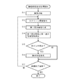
図12は、撮像画像送信処理の流れの一例を示すフローチャートである。撮像画像送信処理は、MFP100が備えるCPU111がROM113、EEPROM115、HDD116またはフラッシュメモリ119Aに記憶された表示制御プログラムを実行することにより、CPU111により実行される処理である。撮像画像送信処理は、上述した発表用データ送信処理と並行して実行される。
FIG. 12 is a flowchart illustrating an example of the flow of captured image transmission processing. The captured image transmission process is a process executed by
図12を参照して、CPU111は、カメラ201を制御して、撮像を開始する(ステップS11)。カメラ201は、動画像を出力するので、CPU111はカメラ201が出力する動画像を取得する。次のステップS12においては、取得された動画像に含まれるフレームからスクリーン領域を抽出する。スクリーン領域は、第1スクリーン204が表された領域である。次のステップS13においては、フレームからスクリーン領域をマスクした第1部分画像を生成する。次のステップS14においては、第1部分画像と、第1部分画像中のスクリーン領域の位置を含む第1表示領域情報とを、他の装置、ここではMFP100AおよびMFP100Bそれぞれに送信する。
Referring to FIG. 12,
次のステップS15においては、ポインタを検出したか否かを判断する。レーザビームのポインタの形状および色を予め記憶しておき、フレームから予め記憶された形状および色の画像を検出した場合に、ポインタを検出したと判断する。ポインタを検出したならば処理をステップS16に進めるが、そうでなければステップS16をスキップして処理をステップS17に進める。ステップS16においては、検出されたポインタのフレーム中の位置を指示位置としてMFP100AおよびMFP100Bに送信する。
In the next step S15, it is determined whether or not a pointer has been detected. The shape and color of the laser beam pointer are stored in advance, and it is determined that the pointer has been detected when an image of the shape and color stored in advance is detected from the frame. If a pointer is detected, the process proceeds to step S16. If not, step S16 is skipped and the process proceeds to step S17. In step S16, the detected position of the pointer in the frame is transmitted to
ステップS17においては、会議終了指示を受け付けたか否かを判断する。会議終了指示を受け付けたならば処理を終了するが、そうでなければ処理をステップS12に戻す。 In step S17, it is determined whether a meeting end instruction has been accepted. If a conference end instruction is accepted, the process ends. If not, the process returns to step S12.
図13は、表示制御処理の流れの一例を示すフローチャートである。表示制御処理は、MFP100が備えるCPU111がROM113、EEPROM115、HDD116またはフラッシュメモリ119Aに記憶された表示制御プログラムを実行することにより、CPU111により実行される処理である。表示制御処理は、上述した発表用データ送信処理および撮像画像送信処理と並行して実行される。
FIG. 13 is a flowchart illustrating an example of the flow of display control processing. The display control process is a process executed by
図13を参照して、CPU111は、配列順番を受け付けたか否かを判断する(ステップS21)。ユーザが、操作部105に配列順番を入力したならば、配列順番を受け付ける。配列順番を受け付けたならば処理をステップS22に進めるが、そうでなければ処理をステップS23に進める。ステップS22においては、受け付けられた配列順番を、MFP100AおよびMFP100Bに送信し、処理をステップS24に進める。ここでは、ユーザが操作部105に、左から順に第3会議室300B、第1会議室300および第2会議室300Aとする配列順番を入力した場合を例に説明する。なお、ここでは、配列順番をユーザが設定する場合を例に説明するが、MFP100,100A,100Bのいずれかにおいて、任意の順番に決定するようにしてもよい。
Referring to FIG. 13,
ステップS23においては、ネットワークI/F119が、MFP100AまたはMFP100Bのいずれかから配列順番を受信したか否かを判断する。MFP100AまたはMFP100Bのいずれかから配列順番を受信したならば処理をステップS24に進めるが、そうでなければ処理をステップS21に戻す。すなわち、表示制御処理は、ユーザが操作部105に配列順番を入力すること、またはMFP100AまたはMFP100Bのいずれかから配列順番を受信することのいずれかを条件に実行される処理である。なお、MFP100,100A,100Bのいずれかが、任意に配列順番を決定する場合には、配列順番が決定された後に、ステップS24以降の処理が実行される。
In step S23, it is determined whether network I /
ステップS24においては、会議室と表示装置との組を決定する。ステップS21において受け付けられた配列順番、またはステップS23において受信された配列順番に基づいて、会議室と表示装置の組を決定する。ここでは、ステップS21において、左から順に第3会議室300B、第1会議室300および第2会議室300Aの配列順番が受け付けられるので、第2会議室300Aと第2表示装置205との組を決定し、第3会議室300Bと第3表示装置207との組を決定する。第2会議室300Aの様子を示す画像を、第1スクリーン204の右側に配置された第2スクリーン206に表示し、第3会議室300Bの様子を示す画像を、第1スクリーン204の左側に配置された第3スクリーン208に表示するためである。
In step S24, a set of a conference room and a display device is determined. Based on the arrangement order received in step S21 or the arrangement order received in step S23, a set of a conference room and a display device is determined. Here, in step S21, since the arrangement order of the
次のステップS25においては、ステップS24において決定された会議室と表示装置との組に基づいて、第1合成画像を生成し、表示する。ステップS26においては、ステップS24において決定された会議室と表示装置との組に基づいて、第2合成画像を生成し、表示する。 In the next step S25, a first composite image is generated and displayed based on the set of the conference room and the display device determined in step S24. In step S26, a second composite image is generated and displayed based on the combination of the conference room and the display device determined in step S24.
ここでは、ステップS24において決定された第2会議室300Aと第2表示装置205との組に基づいて、第1合成画像を生成する。図11において説明した発表用データ送信処理がMFP100Aの備えるCPU111Aにおいて実行されると、第2発表用データが送信される。図12において説明した撮像画像送信処理が、MFP100Aの備えるCPU111Aにおいて実行されると、カメラ201Aにおいて撮像された第2会議室300Aの動画像からスクリーン領域をマスクした第2部分画像と第2表示領域情報が送信される。ステップS25においては、MFP100Aから受信される第2部分画像に、その第2表示領域情報において特定される部分に、第2発表用データを合成することにより第1合成画像を生成する。そして、生成された第1合成画像を、第2表示装置205に出力し、第2スクリーン206に投影させる。これにより、第1合成画像が第2スクリーン206に表示される。
Here, a first composite image is generated based on the set of the
また、図11において説明した発表用データ送信処理がMFP100Bの備えるCPU111Bにおいて実行されると、第3発表用データが送信される。図12において説明した撮像画像送信処理が、MFP100Bの備えるCPU111Bにおいて実行されると、カメラ201Bにおいて撮像された第3会議室300Bの動画像からスクリーン領域をマスクした第3部分画像と第3表示領域情報が送信される。ステップS26においては、MFP100Bから受信される第3部分画像に、その第3表示領域情報において特定される部分に、第3発表用データを合成することにより第2合成画像を生成する。そして、生成された第2合成画像を、第3表示装置205に出力し、第3スクリーン208に投影させる。これにより、第2合成画像が第3スクリーン208に表示される。
In addition, when the presentation data transmission process described with reference to FIG. 11 is executed by CPU 111B of
ステップS27においては、会議終了指示を受け付けたか否かを判断する。会議終了指示を受け付けたならば処理を終了するが、そうでなければ処理をステップS25に戻す。会議終了指示が受け付けられるまで、第1合成画像、換言すれば、第2会議室300Aを撮像した動画像と、第2発表用データを含む画像とを合成した動画像が、第2スクリーン206に表示されるとともに、第2合成画像、換言すれば、第3会議室300Bを撮像した動画像と、第3発表用データを含む画像とを合成した動画像が、第3スクリーン208に表示される。
In step S27, it is determined whether a meeting end instruction has been accepted. If a conference end instruction is accepted, the process ends. If not, the process returns to step S25. Until the conference end instruction is received, a first synthesized image, in other words, a moving image obtained by synthesizing the
図13に示した表示制御処理が、MFP100Aが備えるCPU100Aにおいて実行される場合、ステップS23において、左から順に第3会議室300B、第1会議室300および第2会議室300Aの配列順番がMFP100から受信される。ステップS24においては、第1会議室300と第3表示装置207Aとの組を決定し、第3会議室300Bと第4表示装置209Aとの組を決定する。第1会議室300の様子を示す画像を、第1スクリーン204Aの左側に配置された第3スクリーン208Aに表示し、第3会議室300Bの様子を示す画像を、第3スクリーン208Aの左側に配置された第4スクリーン210Aに表示するためである。
When the display control process shown in FIG. 13 is executed by
そして、ステップS25において、決定された第1会議室300と第3表示装置207Aとの組に基づいて、第1合成画像を生成し、第3表示装置207Aに表示させる。第1合成画像は、MFP100から受信される第1部分画像に、その第1表示領域情報において特定される部分に、第1発表用データを合成した画像である。また、ステップS26においては、決定された第3会議室300Bと第4表示装置209Aとの組に基づいて、第2合成画像を生成し、第4表示装置209Aに表示させる。第2合成画像は、MFP100Bから受信される第3部分画像に、その第3表示領域情報において特定される部分に、第3発表用データを合成した画像である。
In step S25, based on the determined set of the
図13に示した表示制御処理が、MFP100Bが備えるCPU100Bにおいて実行される場合、ステップS23において、左から順に第3会議室300B、第1会議室300および第2会議室300Aの配列順番がMFP100から受信される。ステップS24においては、第1会議室300と第2表示装置205Bとの組を決定し、第2会議室300Aと第3表示装置209Bとの組を決定する。第1会議室300の様子を示す画像を、第1スクリーン204Bの右側に配置された第2スクリーン206Bに表示し、第3会議室300Bの様子を示す画像を、第2スクリーン206Bの右側に配置された第4スクリーン210Bに表示するためである。
When the display control process shown in FIG. 13 is executed by
そして、ステップS25において、決定された第1会議室300と第2表示装置205Aとの組に基づいて、第1合成画像を生成し、第2表示装置205Aに表示させる。第1合成画像は、MFP100から受信される第1部分画像に、その第1表示領域情報において特定される部分に、第1発表用データを合成した画像である。また、ステップS26においては、決定された第3会議室300Bと第4表示装置209Bとの組に基づいて、第2合成画像を生成し、第4表示装置209Bに表示させる。第2合成画像は、MFP100Aから受信される第2部分画像に、その第2表示領域情報において特定される部分に、第2発表用データを合成した画像である。
In step S25, based on the determined set of the
<第2の実施の形態>
第1の実施の形態における会議システム1においては、地理的に離れた3つの第1〜第3会議室300,300A,300Bおいて、第1〜第3発表用データをそれぞれ表示するようにした。第2の実施の形態における会議システム1Aにおいては、地理的に離れた複数の会議室のうち1つの会議室においてのみ発表用データを表示するものである。ここでは、地理的に離れた第1および第2会議室300Aで会議する場合であって、第1会議室300において発表用データを表示する場合を例に説明する。
<Second Embodiment>
In the
図14は、本発明の第2の実施の形態における会議システム全体の概要を示す図である。図14を参照して、第2の実施の形態における会議システム1Aは、ネットワーク2に接続されたMFP100,100Aを含む。MFP100は、第1会議室300に設置され、第1会議室300に設置されたカメラ211および第1および第2表示装置213,215と、接続される。MFP100Aは、第2会議室300Aに設置され、第2会議室300Aに設置されたカメラ221および第3表示装置223と、接続される。
FIG. 14 is a diagram showing an overview of the entire conference system according to the second embodiment of the present invention. Referring to FIG. 14,
第1会議室300に設置されるMFP100は、カメラ211および第1および第2表示装置213,215を制御する制御装置として機能し、第2会議室300Aに設置されるMFP100Aは、カメラ221および第3表示装置223を制御する制御装置として機能する。第1〜第3表示装置213,215,223は、プロジェクタであり、画像をスクリーンに投影する。
The
第1会議室300に設置されるMFP100,100Aのハードウエア構成は、図6に示したのと同じである。また、説明のために、MFP100Aが備える部材および機能に、MFP100が備える部材および機能に付した番号に英字「A」を追加した符号を付す。
The hardware configuration of
図15は、第2の実施の形態における第1会議室におけるカメラ、第1および第2表示装置の配置を示す図である。図15は、第1会議室300を上から見た図である。図15を参照して、第1会議室300には、第1表示装置213が投影する画像が表示される表示面となる第1スクリーン214と、第2表示装置215が投影する画像が表示される表示面となる第2スクリーン216と、カメラ211が配置される。第1および第2表示装置213,215は、第1会議室300の天井に配置され、第1および第2スクリーン214,216とは対面して配置される。カメラ211は、第2スクリーン216の上側に配置され、第1スクリーン214を撮像範囲に含む画角を有する。
FIG. 15 is a diagram showing an arrangement of cameras, first and second display devices in the first conference room in the second embodiment. FIG. 15 is a view of the
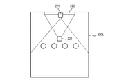
図16は、第2の実施の形態における第2会議室におけるカメラ、第3表示装置の配置を示す図である。図16は、第2会議室300Aを上から見た図である。図16を参照して、第2会議室300Aには、カメラ221と、第3表示装置223と、第3表示装置223が投影する画像が表示される表示面となる第3スクリーン222と、が配置される。第3表示装置223は、第2会議室300Aの天井に配置される。第1および第2スクリーン214,216とは対面して配置される。カメラ221は、第3スクリーン222の上側に配置され、第3スクリーン222側から第2会議室300Aの全体を撮像範囲に含む画角を有する。
FIG. 16 is a diagram illustrating an arrangement of the camera and the third display device in the second conference room according to the second embodiment. FIG. 16 is a view of the
第2の実施の形態における会議システム1Aは、MFP100,100Aが第1および第2仮想会議室をそれぞれ形成する。第1および第2仮想会議室は、第1および第2会議室300,300Aを用いて会議する場合に、MFP100,100Aそれぞれで形成される仮想的な会議室である。MFP100が形成する第1仮想会議室は、第1会議室300に参加する参加者は、第1会議室300内の他の参加者を直接確認し、第2会議室300Aの様子を第2スクリーン216に表示された画像で確認する。MFP100Aが形成する第2仮想会議室は、第2会議室300Aに参加する参加者は、第2会議室300A内の他の参加者を直接確認し、第1会議室300の様子を、第3スクリーン222に表示された画像で確認する。
In the
図17は、第2の実施の形態における第1仮想会議室を形成するMFPが備えるCPUの機能の概要の一例を示すブロック図である。図17に示すCPU111の機能は、CPU111がROM113、EEPROM115、HDD116またはフラッシュメモリ119Aに記憶された表示制御プログラムを実行することにより実現される。
FIG. 17 is a block diagram illustrating an example of an overview of the functions of the CPU provided in the MFP forming the first virtual conference room in the second embodiment. The functions of the
図17を参照して、図7に示した機能と異なる点は、配列決定部65、受信部63、表示画像決定部67、第1合成部69、第2合成部70、第2〜第3表示制御部72,73,74が削除され、受信部75および第2表示制御部77が追加された点である。その他の機能は、図7で説明したのと同じなので、ここでは説明を繰り返さない。
Referring to FIG. 17, the difference from the function shown in FIG. 7 is that
送信部57は、表示データ取得部61から入力される第1発表用データと、第1表示制御部71から入力される第1パラメータとの組を、ネットワークI/F118を介して、MFP100Aに送信する。また、送信部57は、部分画像生成部55から入力される第1部分画像と第1表示領域情報とを、ネットワークI/F118を介して、MFP100Aに送信する。第1部分画像は、例えば、ストリーミング配信の技術を用いて、リアルタイムで送信する。
受信部75は、ネットワークI/F118を制御して、後述するMFP100Aが送信する撮像画像を受信する。撮像画像は動画像である。受信部75は、撮像画像を第2表示制御部77に出力する。
Receiving
第2表示制御部77は、受信部75から撮像画像が入力され、第2表示装置215を制御し、第2表示装置215に撮像画像を表示させる。第2表示制御部77は、第2表示装置215に撮像画像を投影させるので、第2スクリーン216に第2会議室300Aを第3スクリーン222側から撮像した画像が表示される。
The second
図18は、第2の実施の形態における第2仮想会議室を形成するMFPが備えるCPUの機能の概要の一例を示すブロック図である。図18に示すCPU111Aの機能は、CPU111AがROM113、EEPROM115、HDD116またはフラッシュメモリ119Aに記憶された表示制御プログラムを実行することにより実現される。
FIG. 18 is a block diagram illustrating an example of an overview of the functions of the CPU provided in the MFP forming the second virtual conference room according to the second embodiment. The functions of the
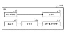
図18を参照して、CPU111Aは、撮像制御部91と、送信部92と、受信部93と、合成部95と、第3表示制御部97と、を含む。
Referring to FIG. 18,
撮像制御部91は、カメラ221を制御し、カメラ221が撮像して出力する動画像を取得する。カメラ221は、上述したように、その画角が第2会議室300Aの全体を撮像範囲に含む画角を有する。このため、カメラ221が出力する動画像は、第2会議室300Aの参加者を含む画像である。撮像制御部91は、カメラ221から取得される動画像をリアルタイムで送信部92に出力する。
The
送信部92は、撮像制御部91から入力される動画像を撮像画像として、ネットワークI/F118Aを介して、MFP100に送信する。受信部93は、ネットワークI/F118Aを制御して、MFP100が送信する第1発表用データと第1パラメータとの組、第1部分画像と第1表示領域情報との組を受信する。受信部93は、第1発表用データと第1パラメータとの組、第1部分画像と第1表示領域情報との組を、合成部95に出力する。
The
合成部95は、第1部分画像の第1表示領域情報で特定されるスクリーン領域に、第1発表用データを合成した合成画像を生成する。合成部95は、第3表示装置223を制御する第3表示制御部97に、生成された合成画像を出力する。より詳細には、合成部95は、第1表示領域情報により特定される第1部分画像中のスクリーン領域を検知し、検知した第1部分画像中のスクリーン領域に基づいて、スクリーン係数を算出する。そして、算出されたスクリーン係数および第1パラメータに基づいて、発表用データの画像を変形する。具体的には、スクリーン係数に基づいて第1発表用データの画像を縮小するとともに、第1パラメータに基づいて発表用画像の色温度を変更する。発表用画像は、第1パラメータに基づいて色温度が変更されるため、第1会議室300で表示されている第1発表用データの画像と同じ色温度の画像となる。合成部95は、第1表示領域情報が指示位置を含む場合、合成画像の指示位置で特定される部分に、レーザポインタが照射されたことを示す画像を合成する。
The combining
第3表示制御部97は、第3表示装置223に合成画像を投影させるので、第3スクリーン222に合成画像が表示される。合成画像は、第1会議室300を撮像した画像を含む。
Since the third
第2の実施の形態における会議システムにおいては、第1会議室300の参加者は、第2スクリーン216に表示された画像から第2会議室300Aに参加している参加者を確認することができ、第2会議室300Aの参加者は、第3スクリーン222に表示された画像から第1会議室に参加している参加者を確認することができる。
In the conference system according to the second embodiment, the participants in the
<変形例>
第2の実施の形態における会議システム1Aにおいては、第2会議室と同じ構成の第3会議室を追加することができる。この場合、MFP100が備えるCPU111が有する受信部75は、MFP100Aから第2会議室を撮像した動画像を受信するのに加えて、第3会議室に設置されたMFP100Bから第3会議室を撮像した動画像を受信する。第2表示制御部77は、第2会議室を撮像した動画像と、第3会議室を撮像した動画像とを、横に並べた1つの合成画像を生成し、生成された合成画像を第2表示装置215に表示させる。
<Modification>
In the
図19は、第2の実施の形態の変形例における仮想会議室を模式的に示す図である。図19を参照して、第2会議室300Aにおいて、第3スクリーン222には、第1会議室300を撮像した動画像が表示され、カメラ221によって第3スクリーン222側から第2会議室300Aが撮像される。第3会議室300Bにおいて、第3スクリーン222Bには、第1会議室300を撮像した動画像が表示され、カメラ221Bによって第3スクリーン222B側から第3会議室300Aが撮像される。
FIG. 19 is a diagram schematically illustrating a virtual conference room according to a modification of the second embodiment. Referring to FIG. 19, in the
したがって、第2会議室300Aの第3スクリーン222と、第3会議室300Bの第3スクリーン222Bとには、同じ動画像が表示される。第1会議室300の第2スクリーン216には、第2会議室300Aを撮像した動画像と、第3会議室300Bを撮像した動画像とが表示される。このため、第1会議室300にいる発表者305は、第1会議室300にいる他の参加者を直接確認することができるとともに、第2スクリーン216に表示された画像から第2会議室300Aおよび第3会議室300Bにいる参加者を確認することができる。一方、第2会議室300Aの参加者は、第3スクリーン222に表示された画像から第1会議室300に参加している参加者を確認することができ、第3会議室300Bの参加者は、第3スクリーン222Bに表示された画像から第1会議室300に参加している参加者を確認することができる。
Therefore, the same moving image is displayed on the
なお、上述した実施の形態においては、制御装置の一例としてMFP100,100A,100Bを説明したが、図11〜図13に示した処理をMFP100,100A,100Bに実行させるための表示制御方法または、その表示制御方法をコンピュータに実行させるための表示制御プログラムとして発明を捉えることができるのは言うまでもない。
In the above-described embodiment,
今回開示された実施の形態はすべての点で例示であって制限的なものではないと考えられるべきである。本発明の範囲は上記した説明ではなくて特許請求の範囲によって示され、特許請求の範囲と均等の意味および範囲内でのすべての変更が含まれることが意図される。 The embodiment disclosed this time should be considered as illustrative in all points and not restrictive. The scope of the present invention is defined by the terms of the claims, rather than the description above, and is intended to include any modifications within the scope and meaning equivalent to the terms of the claims.
1、1A 会議システム、2 ネットワーク、9 操作パネル、10 ADF、20 原稿読取部、30 画像形成部、40 給紙部、51 撮像制御部、53 スクリーン領域抽出部、55 部分画像生成部、57 送信部、59 操作受付部、61 表示データ取得部、63 受信部、65 配列決定部、67 表示画像決定部、69 第1合成部、70 第2合成部、71 第1表示制御部、72 第2表示制御部、73 第3表示制御部、74 第4表示制御部、75 受信部、77 第2表示制御部、81 スクリーン領域検知部、83 スクリーン係数決定部、85 発表用画像取得部、87 変形部、89 発表画像合成部、90 画像調整部、91 撮像制御部、92 送信部、93 受信部、95 合成部、97 第3表示制御部、100,100A,100B MFP、101 メイン回路、103 表示部、105 操作部、111 CPU、112 通信I/F部、113 ROM、114 RAM、115,115A EEPROM、116 HDD、117 ファクシミリ部、118 ネットワークI/F、119 カードI/F、119A フラッシュメモリ、201,201A,201B カメラ、203,203A,203B 第1表示装置、204,204A,204B 第1スクリーン、205,205A,205B 第2表示装置、206,206A,206B 第2スクリーン、207,207A,207B 第3表示装置、208,208A,208B 第3スクリーン、209,209A,209B 第4表示装置、210,210A,210B 第4スクリーン、211,221 カメラ、213,215,223 第1〜第3表示装置、214,216,222 第1〜第3スクリーン。 1, 1A conference system, 2 network, 9 operation panel, 10 ADF, 20 document reading unit, 30 image forming unit, 40 paper feeding unit, 51 imaging control unit, 53 screen area extracting unit, 55 partial image generating unit, 57 transmission Unit, 59 operation accepting unit, 61 display data acquiring unit, 63 receiving unit, 65 arrangement determining unit, 67 display image determining unit, 69 first combining unit, 70 second combining unit, 71 first display control unit, 72 second Display control unit, 73 Third display control unit, 74 Fourth display control unit, 75 Receiving unit, 77 Second display control unit, 81 Screen area detection unit, 83 Screen coefficient determination unit, 85 Presentation image acquisition unit, 87 89, Presentation image composition unit, 90 Image adjustment unit, 91 Imaging control unit, 92 Transmission unit, 93 Reception unit, 95 Composition unit, 97 Third display control unit, 100, 100 A, 100B MFP, 101 main circuit, 103 display unit, 105 operation unit, 111 CPU, 112 communication I / F unit, 113 ROM, 114 RAM, 115, 115A EEPROM, 116 HDD, 117 facsimile unit, 118 network I / F 119 Card I / F, 119A Flash memory, 201, 201A, 201B Camera, 203, 203A, 203B First display device, 204, 204A, 204B First screen, 205, 205A, 205B Second display device, 206, 206A , 206B second screen, 207, 207A, 207B third display device, 208, 208A, 208B third screen, 209, 209A, 209B fourth display device, 210, 210A, 210B fourth screen, 211, 221 Camera, 213, 215, 223 First to third display devices, 214, 216, 222 First to third screens.
Claims (9)
前記第1〜第3の会議室それぞれに、
第1表示面に発表用画像を表示する第1表示装置と、
前記第1表示装置の前記第1表示面および該会議室に参加する参加者を含む画角で撮像し、会議室画像を出力する撮像装置と、
別の2つの会議室それぞれに配置された前記撮像装置により撮像された2つの会議室画像を第2表示面および第3表示面にそれぞれ表示する第2表示装置および第3表示装置と、
前記第1表示装置、前記撮像装置、前記第2表示装置および前記第3表示装置を制御する制御装置と、を配置し、
前記第1表示装置、第2表示装置および第3表示装置は、前記第1表示装置が画像を表示する第1表示面、前記第2表示装置が画像を表示する第2表示面、および前記第3表示装置が画像を表示する第3表示面の向きが互いに異なるように配置され、
前記制御装置は、前記第1〜第3会議室でそれぞれの配置が共通となる配列を決定する配列決定手段と、
前記決定された配列に従って、別の2つの会議室それぞれに配置された前記撮像装置により撮像された2つの会議室画像それぞれを前記第2表示装置および前記第3表示装置のいずれに表示させるかを決定する表示画像決定手段と、を備えた会議システム。 A conference system that generates a virtual conference room using a plurality of images obtained by imaging the first, second, and third conference rooms that are geographically separated,
In each of the first to third meeting rooms,
A first display device for displaying an image for presentation on the first display surface;
An imaging device that captures an image at an angle of view including the first display surface of the first display device and participants who participate in the conference room, and outputs a conference room image;
A second display device and a third display device for displaying two conference room images captured by the imaging devices respectively disposed in two different conference rooms on a second display surface and a third display surface, respectively;
A control device for controlling the first display device, the imaging device, the second display device, and the third display device;
The first display device, the second display device, and the third display device include a first display surface on which the first display device displays an image, a second display surface on which the second display device displays an image, and the second display device. The three display devices are arranged so that the directions of the third display surfaces for displaying images are different from each other,
The control device includes an arrangement determining means for determining an arrangement in which the respective arrangements are common in the first to third meeting rooms,
According to the determined arrangement, which of the second display device and the third display device displays each of the two conference room images captured by the imaging device disposed in each of the other two conference rooms. And a display image determining means for determining.
別の2つの会議室にそれぞれ配置された2つの前記制御装置それぞれから送信される部分画像と発表用画像とを受信する受信手段と、
前記受信された部分画像の前記画面部分に前記受信された発表用画像を合成した合成画像を生成する合成手段と、
前記合成された2つの合成画像のうち前記表示画像決定手段により決定された一方を前記第2表示装置に表示させる第2表示制御手段と、
前記合成された2つの合成画像のうち前記表示画像決定手段により決定された他方を前記第3表示装置に表示させる第3表示制御手段と、を備える請求項1または2のいずれかに記載の会議システム。 The control device includes a partial image obtained by removing a screen portion on which the first display surface is displayed from conference room images output by the imaging device, and a presentation image displayed by the first display device. Transmitting means for transmitting to two other meeting rooms;
Receiving means for receiving a partial image and a presentation image transmitted from each of the two control devices respectively disposed in two other conference rooms;
Combining means for generating a combined image obtained by combining the received presentation image with the screen portion of the received partial image;
Second display control means for causing the second display device to display one of the two synthesized images synthesized by the display image determining means;
3. A conference according to claim 1, further comprising third display control means for causing the third display device to display the other of the two synthesized images synthesized by the display image determining means. system.
前記受信手段は、別の2つの会議室それぞれに配置された前記送信手段から前記色プロファイルをさらに受信し、
前記合成手段は、前記受信された色プロファイルと、前記第2表示装置および第3表示装置それぞれの色プロファイルとに従って、色補正量を決定し、前記受信された発表用画像を補正する画像調整手段を含む、請求項3に記載の会議システム。 The transmission means further transmits the color profile of the first display device to two other conference rooms,
The reception means further receives the color profile from the transmission means arranged in each of two other conference rooms,
The synthesizing unit determines an amount of color correction according to the received color profile and the color profiles of the second display device and the third display device, and corrects the received presentation image. The conference system according to claim 3, comprising:
前記第3表示制御手段は、前記受信された部分画像の前記画面部分が前記部分画像に占める割合が所定の値以下の場合、前記第3表示装置に、前記合成画像に代えて前記受信された発表用画像のみを表示させる、請求項3または4に記載の会議システム。 When the ratio of the screen portion of the received partial image to the partial image is equal to or less than a predetermined value, the second display control unit is configured to display the received announcement instead of the composite image on the second display device. Display only the image for
When the ratio of the screen portion of the received partial image to the partial image is equal to or less than a predetermined value, the third display control unit receives the received image on the third display device instead of the composite image. The conference system according to claim 3 or 4, wherein only a presentation image is displayed.
前記第1の会議室に、
第1表示面に発表用画像を表示する第1表示装置と、
前記発表用画像が表示された前記第1表示面および該第1の会議室に参加する参加者を含む画角で撮像した第1会議室画像を出力する第1撮像装置と、
画像を第1表示面と対向して配置された第2表示面に表示する第2表示装置と、
前記第1表示装置と、前記第1撮像装置と、前記第2表示装置と、を制御する第1制御装置と、を配置し、
前記第1制御装置は、前記第1会議室画像を前記第2の会議室に送信する第1送信手段と、
前記第2会議室から画像を受信する第1受信手段と、を備え、
前記第2の会議室に、
前記第1会議室画像を第3表示面に表示する第3表示装置と、
前記第3表示面側から前記第2の会議室に参加する参加者を含む画角で撮像した第2会議室画像を出力する第2撮像装置と、
前記第3表示装置および前記第2撮像装置を制御する第2制御装置と、を配置し、
前記第2制御装置は、前記第1会議室画像を受信する第2受信手段と、
前記第2会議室画像を前記第1の会議室に送信する第2送信手段と、を備え、
前記第1制御装置は、第1受信手段が受信した前記第2会議室画像を、第2表示面に表示させるよう第2表示装置を制御する会議システム。 A conference system that generates a virtual conference room using two images obtained by imaging first and second conference rooms that are geographically separated,
In the first meeting room,
A first display device for displaying the presentation image on the first display surface,
A first imaging device for outputting a first conference room image captured by angle including participants the presentation image join has been the first display surface and the first conference room display,
A second display device for displaying the second display surface disposed the images faces the first display surface,
A first control device that controls the first display device, the first imaging device, and the second display device;
The first control device includes first transmission means for transmitting the first meeting room image to the second meeting room;
First receiving means for receiving an image from the second conference room,
In the second meeting room,
A third display device for displaying the first conference room image on a third display surface;
A second imaging device that outputs a second conference room image captured at an angle of view including participants who participate in the second conference room from the third display surface side;
A second control device that controls the third display device and the second imaging device;
The second control device includes second receiving means for receiving the first conference room image;
Second transmission means for transmitting the second conference room image to the first conference room ,
The first control unit, conference system the second conference room image first received by the receiving means, that controls the second display device so as to be displayed on the second display surface.
前記第2表示装置は、複数の前記第2の会議室からそれぞれ受信される複数の前記第2会議室画像を並べて表示する、請求項6に記載の会議システム。 There are a plurality of the second meeting rooms,
The conference system according to claim 6, wherein the second display device displays a plurality of the second conference room images respectively received from the plurality of second conference rooms.
前記第2制御装置は、前記第1制御装置から送信される部分画像と発表用画像とを受信する受信手段と、The second control device receives a partial image and a presentation image transmitted from the first control device;
前記受信された部分画像の前記画面部分に前記受信された発表用画像を合成した合成画像を生成する合成手段と、Combining means for generating a combined image obtained by combining the received presentation image with the screen portion of the received partial image;
前記合成画像を前記第3表示装置に表示させる表示制御手段と、を備える請求項6または7のいずれかに記載の会議システム。The conference system according to claim 6, further comprising display control means for displaying the composite image on the third display device.
前記受信手段は、前記送信手段から前記色プロファイルをさらに受信し、The receiving means further receives the color profile from the transmitting means;
前記合成手段は、前記受信された色プロファイルと、前記第3表示装置の色プロファイルとに従って、色補正量を決定し、前記受信された発表用画像を補正する画像調整手段を含む、請求項8に記載の会議システム。9. The composition unit includes an image adjustment unit that determines a color correction amount according to the received color profile and a color profile of the third display device and corrects the received presentation image. The conference system described in 1.
Priority Applications (1)
| Application Number | Priority Date | Filing Date | Title |
|---|---|---|---|
| JP2010140599A JP5381908B2 (en) | 2010-06-21 | 2010-06-21 | Conference system |
Applications Claiming Priority (1)
| Application Number | Priority Date | Filing Date | Title |
|---|---|---|---|
| JP2010140599A JP5381908B2 (en) | 2010-06-21 | 2010-06-21 | Conference system |
Publications (2)
| Publication Number | Publication Date |
|---|---|
| JP2012005039A JP2012005039A (en) | 2012-01-05 |
| JP5381908B2 true JP5381908B2 (en) | 2014-01-08 |
Family
ID=45536460
Family Applications (1)
| Application Number | Title | Priority Date | Filing Date |
|---|---|---|---|
| JP2010140599A Expired - Fee Related JP5381908B2 (en) | 2010-06-21 | 2010-06-21 | Conference system |
Country Status (1)
| Country | Link |
|---|---|
| JP (1) | JP5381908B2 (en) |
Family Cites Families (5)
| Publication number | Priority date | Publication date | Assignee | Title |
|---|---|---|---|---|
| JPH06351013A (en) * | 1993-06-08 | 1994-12-22 | Matsushita Electric Ind Co Ltd | Electronic conference system |
| JP4363672B2 (en) * | 1996-04-05 | 2009-11-11 | ソニー株式会社 | Video conference system and method, and communication center |
| JPH1127646A (en) * | 1997-06-30 | 1999-01-29 | Canon Inc | Image processing apparatus and image processing method |
| JP2000122767A (en) * | 1998-10-14 | 2000-04-28 | Nippon Telegr & Teleph Corp <Ntt> | Method and apparatus for creating a shared space having the same room and communication system |
| JP2006339832A (en) * | 2005-05-31 | 2006-12-14 | Nippon Telegr & Teleph Corp <Ntt> | Video conference system and video conference terminal device |
-
2010
- 2010-06-21 JP JP2010140599A patent/JP5381908B2/en not_active Expired - Fee Related
Also Published As
| Publication number | Publication date |
|---|---|
| JP2012005039A (en) | 2012-01-05 |
Similar Documents
| Publication | Publication Date | Title |
|---|---|---|
| KR101003277B1 (en) | Computer-implemented method and multi-imager system for producing seamless composite images | |
| JP6171263B2 (en) | Remote conference system and remote conference terminal | |
| JP2009265692A (en) | Notebook type information processor and image reading method | |
| WO2010137513A1 (en) | Electronic device | |
| JP2007201948A (en) | Imaging apparatus, image processing method, and program | |
| US9888209B1 (en) | Remote communication system, method for controlling remote communication system, and storage medium | |
| JP4581210B2 (en) | Video conference system | |
| JP2007010807A (en) | Information processing system, information processing device, information processing method and computer program | |
| JP6584237B2 (en) | Control device, control method, and program | |
| JP2009071478A (en) | Information communication terminal and information communication system | |
| JP6662264B2 (en) | Display system | |
| US20080055564A1 (en) | Interactive document camera and system of the same | |
| US7929185B2 (en) | System and method for switching screens from overview and preview | |
| JP2018037857A (en) | Image processing apparatus, image processing method, and program | |
| JP2013016933A (en) | Terminal device, imaging method, and program | |
| JP2011048295A (en) | Compound eye photographing device and method for detecting posture of the same | |
| JP5381908B2 (en) | Conference system | |
| JP6627448B2 (en) | Print production equipment | |
| JP6697726B1 (en) | Image processing device, scanner, projector, image processing method, program | |
| JP6778399B2 (en) | Image reader, image forming device, image reading method and image reading program | |
| JP2020188358A (en) | Electronic device, control method of the same, program, and storage medium | |
| JP2010278511A (en) | Electronic equipment | |
| US20070098394A1 (en) | Image capture device output settings module | |
| JP2005130312A (en) | Stereoscopic image processing apparatus, computer program, and parallax correction method | |
| JP2008124830A (en) | Imaging apparatus |
Legal Events
| Date | Code | Title | Description |
|---|---|---|---|
| A621 | Written request for application examination |
Free format text: JAPANESE INTERMEDIATE CODE: A621 Effective date: 20120626 |
|
| A711 | Notification of change in applicant |
Free format text: JAPANESE INTERMEDIATE CODE: A712 Effective date: 20130417 |
|
| A977 | Report on retrieval |
Free format text: JAPANESE INTERMEDIATE CODE: A971007 Effective date: 20130613 |
|
| A131 | Notification of reasons for refusal |
Free format text: JAPANESE INTERMEDIATE CODE: A131 Effective date: 20130625 |
|
| A521 | Written amendment |
Free format text: JAPANESE INTERMEDIATE CODE: A523 Effective date: 20130819 |
|
| TRDD | Decision of grant or rejection written | ||
| A01 | Written decision to grant a patent or to grant a registration (utility model) |
Free format text: JAPANESE INTERMEDIATE CODE: A01 Effective date: 20130903 |
|
| A61 | First payment of annual fees (during grant procedure) |
Free format text: JAPANESE INTERMEDIATE CODE: A61 Effective date: 20130916 |
|
| R150 | Certificate of patent or registration of utility model |
Free format text: JAPANESE INTERMEDIATE CODE: R150 |
|
| LAPS | Cancellation because of no payment of annual fees |