JP5380010B2 - Branch adapter - Google Patents
Branch adapter Download PDFInfo
- Publication number
- JP5380010B2 JP5380010B2 JP2008188873A JP2008188873A JP5380010B2 JP 5380010 B2 JP5380010 B2 JP 5380010B2 JP 2008188873 A JP2008188873 A JP 2008188873A JP 2008188873 A JP2008188873 A JP 2008188873A JP 5380010 B2 JP5380010 B2 JP 5380010B2
- Authority
- JP
- Japan
- Prior art keywords
- bridge
- transformer
- branch
- elements
- impedance
- Prior art date
- Legal status (The legal status is an assumption and is not a legal conclusion. Google has not performed a legal analysis and makes no representation as to the accuracy of the status listed.)
- Expired - Fee Related
Links
- 230000005540 biological transmission Effects 0.000 claims description 29
- 239000003990 capacitor Substances 0.000 claims description 10
- 230000008878 coupling Effects 0.000 claims description 7
- 238000010168 coupling process Methods 0.000 claims description 7
- 238000005859 coupling reaction Methods 0.000 claims description 7
- 238000004804 winding Methods 0.000 claims description 3
- 230000002457 bidirectional effect Effects 0.000 description 7
- 239000004020 conductor Substances 0.000 description 7
- 238000009413 insulation Methods 0.000 description 3
- 239000000758 substrate Substances 0.000 description 3
- 238000011144 upstream manufacturing Methods 0.000 description 3
- 238000010586 diagram Methods 0.000 description 2
- WABPQHHGFIMREM-UHFFFAOYSA-N lead(0) Chemical compound [Pb] WABPQHHGFIMREM-UHFFFAOYSA-N 0.000 description 2
- 229910000859 α-Fe Inorganic materials 0.000 description 2
- 230000006866 deterioration Effects 0.000 description 1
- 230000000694 effects Effects 0.000 description 1
- 239000002184 metal Substances 0.000 description 1
- 229920003002 synthetic resin Polymers 0.000 description 1
- 239000000057 synthetic resin Substances 0.000 description 1
Images

Landscapes
- Cable Transmission Systems, Equalization Of Radio And Reduction Of Echo (AREA)
Description
本発明は、伝送路を流れている高周波信号を多数に分岐するとともに、伝送路の双方向に対してインピーダンスの整合、及びロスの最小化がとれた分岐アダプタに関するものである。 The present invention relates to a branch adapter that branches a large number of high-frequency signals flowing through a transmission line, and that can match impedance and minimize loss in both directions of the transmission line.
伝送路を流れている高周波信号を分岐(分配)するための分岐アダプタ(分配器)としては、例えば、CATV等の高周波信号を分岐する手段として各種の分岐アダプタが提案されている。このような分岐アダプタは、一つのトランスを用いて2分岐の出力を備えた2分岐アダプタ、あるいは複数のトランスを組み合せた電気回路により、多分岐の出力を備えた多分岐アダプタが提案されている。 As branch adapters (distributors) for branching (distributing) a high-frequency signal flowing through a transmission line, various branch adapters have been proposed as means for branching high-frequency signals such as CATV. As such a branch adapter, a two-branch adapter having a two-branch output using a single transformer or a multi-branch adapter having a multi-branch output by an electric circuit combining a plurality of transformers has been proposed. .
2分岐の出力端子を備えた2分岐アダプタとしては、例えば、下記の特許文献1に記載の発明が提案されている。特許文献1には、CATV等の高周波信号を分岐する分配器として、基板上に、単一のフェライトコアに巻線を施したインピーダンス整合用トランスT1と信号用分配トランスT2を配設して、これら整合用トランスT1と分配トランスT2とを金属板で結合した高周波信号分配器が記載されている。さらに、特許文献1には、整合用トランスT1は、この整合用トランスT1の出力インピーダンスが周波数に対し一定になるように、補正用の抵抗RsおよびコンデンサCsを介して接地させることが記載されている。
As a two-branch adapter having a two-branch output terminal, for example, the invention described in
多分岐の出力端子を備えた分岐アダプタとしては、例えば、下記の特許文献2に記載の発明が提案されている。特許文献2には、CATVシステム等に使用される高周波信号を6等分する6分配器として、入力端子側から第1の分配トランスT10(2分配トランス)と、第1の整合トランスT20と、第2の分配トランスT30(3分配トランス)と、第2の整合トランスT40とをこの順に配列した構成とした6分配器が記載されている。さらに、特許文献2には、上記のように各トランスを配置することにより高周波信号の高域における劣化を抑え、安定したインピーダンスを得ることができることが記載されている。
As a branch adapter provided with a multi-branch output terminal, for example, the invention described in
上記特許文献1に記載の高周波信号分配器は、インピーダンス整合用トランスT1と信号用分配トランスT2を配設することにより、高周波信号を2分岐する分配器であって、高周波信号をさらに3分岐以上に多分岐するための構成については開示されていない。また、特許文献1に記載の高周波信号分配器は、高周波信号が入力端子側から出力端子側へと一方向に流れるときのインピーダンス整合をとる手段は設けられているが、この分配器は、高周波信号を出力端子側から入力端子側に流すための分配器、すなわち、伝送路に高周波信号を双方向に流すために使用するための分配器ではない。
The high-frequency signal distributor described in
上記特許文献2に記載の6分配器は、入力端子側から第1の分配トランスT10(2分配トランス)と、第1の整合トランスT20と、第2の分配トランスT30(3分配トランス)と、第2の整合トランスT40とをこの順に配列した構成にすることにより、6分配した分配器であるが、上記特許文献1と同様に、伝送路に高周波信号を双方向に流すために使用するための分配器ではない。
The 6 distributor described in
データ通信を行なうための通信線を備えたネットワークシステムにおいては、この通信線(伝送路)にはデータ信号となる高周波信号が双方向に流れる。そして、このネットワークシステムに多数の端末装置を接続する場合には、この伝送路を多数に分岐する必要が生じる場合がある。例えば、AC100Vの電力線を利用して通信を行なうPLC(Power Line Communication)通信を用いたネットワークシステムである。 In a network system including a communication line for performing data communication, a high-frequency signal serving as a data signal flows bidirectionally on the communication line (transmission path). When a large number of terminal devices are connected to the network system, it may be necessary to branch the transmission path into a large number. For example, it is a network system using PLC (Power Line Communication) communication that performs communication using an AC 100V power line.
例えば、大規模ビルディング等において、各フロアに配置されているパーソナルコンピュータ等の端末装置や各種の電気(電子)機器等を、PLC通信を用いたネットワークで接続する場合には、フロアに配線された電力線をさらに多数に分岐してこれら電子機器に接続する必要が生じる。上記した特許文献1及び2には、上記したネットワークシステムの伝送路において、双方向に高周波信号を流すことを目的とした分岐アダプタではない。
For example, in a large-scale building or the like, when connecting a terminal device such as a personal computer or various electric (electronic) devices arranged on each floor via a network using PLC communication, it is wired to the floor. It is necessary to branch the power line into a larger number and connect it to these electronic devices.
そこで、本発明の目的は、高周波信号を多数に分岐することができるとともに、双方向に高周波信号を流してもインピーダンス整合がとれ、かつ、分岐ロスを最小化することができる分岐アダプタを提供することにある。特に、本発明は、PLC通信を用いたネットワークシステムの伝送路を多数に分岐するための分岐アダプタを提供することにある。 SUMMARY OF THE INVENTION Accordingly, an object of the present invention is to provide a branch adapter that can branch a high-frequency signal into a large number, can achieve impedance matching even when a high-frequency signal is passed in both directions, and can minimize branch loss. There is. In particular, the present invention is to provide a branch adapter for branching a transmission line of a network system using PLC communication into a large number.
上記した課題を解決するために、請求項1に記載の発明に係る分岐アダプタは、4個のインピーダンス素子により構成したブリッジの一方の対角に1個のインピーダンス素子を接続し、他方の対角に1個のインピーダンス素子を接続したブリッジ回路であって、前記ブリッジを構成する4個のインピーダンス素子を4個のトランス素子により構成するとともに、各トランスの二次側を接続することにより前記ブリッジを構成し、前記一方の対角に接続される1個のインピーダンス素子をトランス素子により構成するとともに、当該トランス素子の二次側を前記ブリッジの一方の対角に接続し、前記他方の対角に接続される1個のインピーダンス素子を抵抗により構成し、前記一方の対角に接続されるトランス素子の一次側を伝送データとなる高周波信号が入力される入力端子とするとともに、前記ブリッジを構成する4個のトランス素子各々の一次側を外部機器が接続される出力端子とした、ことを特徴としている。
In order to solve the above-described problem, the branch adapter according to the invention described in
また、請求項2に記載の発明に係る分岐アダプタは、トランス素子の二次側の一方どうしを接続した二つのトランス素子から構成される2組について、その各組の前記トランス素子の他の二次側どうしを連結するとともに、当該連結した二次側どうしを、抵抗を介して接続した4個のトランス素子の組合せを有する回路と、一次側を伝送データとなる高周波信号が入力される入力端子とした分岐前ポート用トランス素子を備え、前記分岐前ポート用トランス素子の二次側の一方を前記二つのトランス素子の二次側の一方どうしを接続した一方の接続部に接続し、前記分岐前ポート用トランス素子の二次側の他方を前記二つのトランス素子の二次側の一方どうしを接続した他方の接続部に接続した構成からなり、前記4個のトランス素子の一次側を、外部機器が接続される出力端子である分岐後ポートとした、ことを特徴としている。 The branch adapter according to the second aspect of the present invention relates to two sets of two transformer elements in which one of the secondary sides of the transformer elements is connected to each other. A circuit having a combination of four transformer elements in which the secondary sides are connected to each other and the connected secondary sides are connected through a resistor, and an input terminal to which a high-frequency signal serving as transmission data is input on the primary side A pre-branch port transformer element, wherein one of the secondary sides of the pre-branch port transformer element is connected to one connecting portion connecting the secondary sides of the two transformer elements, and the branch consists arrangement connected the other of the secondary side before transformer device port to the other connection portion connecting the hand each other on the secondary side of the two transformer device, the primary of the four transformer element Were a branch after the port is an output terminal of an external device is connected, it is characterized in that.
また、請求項3に記載の発明に係る分岐アダプタは、トランス素子の二次側の一方どうしを接続した二つのトランス素子から構成される2組について、その各組の前記トランス素子の他の二次側どうしを連結するとともに、当該連結した二次側どうしを、抵抗を介して接続した4個のトランス素子の組合せを有するブリッジ構成であるブリッジ1と、ブリッジ2と、ブリッジ3と、ブリッジ4と、一次側を伝送データとなる高周波信号が入力される入力端子とした分岐前ポート用トランス素子と、を備え、前記ブリッジ1と前記ブリッジ2の前記抵抗を介して接続された二次側ではない一方の二次側どうしを接続するとともに、前記分岐前ポート用トランス素子の二次側の一方に接続し、前記ブリッジ3と前記ブリッジ4の前記抵抗を介して接続された二次側ではない一方の二次側どうしを接続するとともに、前記分岐前ポート用トランス素子の二次側の他方に接続し、前記ブリッジ1と前記ブリッジ3の前記抵抗を介して接続された二次側ではない他方の二次側どうしを接続(以下、ブリッジ1−3間という)し、前記ブリッジ2と前記ブリッジ4の前記抵抗を介して接続された二次側ではない他方の二次側どうしを接続する(以下、ブリッジ2−4間という)とともに、前記ブリッジ1−3間と前記ブリッジ2−4間とを抵抗を介して接続し、前記ブリッジ1および、前記ブリッジ2および、前記ブリッジ3および、前記ブリッジ4を構成する16個のトランス素子の一次側を、外部機器が接続される出力端子である分岐後ポートとした、ことを特徴としている。
According to the third aspect of the present invention, there is provided a branch adapter according to the present invention, wherein two sets of two transformer elements connected to each other on the secondary side of a transformer element are connected to the other two transformer elements.
また、請求項4に記載の発明は、請求項1から請求項3のいずれかに記載の分岐アダプタに係り、前記トランス素子は、その一次側と二次側の巻線比は1:1とされていることを特徴としている。 According to a fourth aspect of the present invention, there is provided the branch adapter according to any one of the first to third aspects, wherein the transformer element has a winding ratio of 1: 1 between the primary side and the secondary side. It is characterized by being.
また、請求項5に記載の発明は、請求項1から請求項4のいずれかに記載の分岐アダプタに係り、前記トランス素子の一次側は、その接続ポートと前記一次側との間に接続された結合コンデンサを備えていることを特徴としている。 A fifth aspect of the present invention relates to the branch adapter according to any of the first to fourth aspects, wherein the primary side of the transformer element is connected between the connection port and the primary side. It is characterized by having a coupling capacitor.
また、請求項6に記載の発明は、請求項1から請求項5のいずれかに記載の分岐アダプタに係り、前記トランス素子の一次側は、その接続ポート間に設けた終端抵抗を作動させるためのスイッチ手段を備えていることを特徴としている。
The invention according to claim 6 relates to the branch adapter according to any one of
本発明によれば、一次二次コイルの巻線比を1:1にした5個のトランス素子を、ブリッジ構成の回路を形成するように接続した構成を備え、さらに、ブリッジ構成の回路に50Ωのインピーダンス素子を備えているので、伝送路における高周波信号の双方向の分岐ロスを最小化することができ、さらに、伝送路の双方向のインピーダンス整合をとることができる4分岐の分岐アダプタを提供することができる。 According to the present invention, it is provided with a configuration in which five transformer elements having a primary / secondary coil turns ratio of 1: 1 are connected so as to form a bridge-structured circuit. Since the impedance element is provided, it is possible to minimize the bidirectional branch loss of the high-frequency signal in the transmission line, and further provide a four-branch branch adapter capable of matching the bidirectional impedance of the transmission line. can do.
本発明は、さらに、5個のトランス素子をブリッジ構成の回路を形成するように接続した4組を、ブリッジ構成の回路を形成するように多重構造とすることにより、16分岐の分岐アダプタを提供することができる。
また、本発明の分岐アダプタは、分岐後ポートに終端抵抗を接続することにより、2分岐〜15分岐を備えた分岐アダプタとして使用することができるようになる。これにより、本発明は、特に、多数の端末装置を接続したPLC通信を用いたネットワークシステムの伝送路を、多数に分岐するための分岐アダプタとして効果を発揮することができる。
The present invention further provides a 16-branch branch adapter by forming four sets of five transformer elements connected so as to form a bridge-structured circuit into a multiple structure so as to form a bridge-structured circuit. can do.
Further, the branch adapter of the present invention can be used as a branch adapter having 2 to 15 branches by connecting a termination resistor to the post-branch port. Thereby, especially this invention can exhibit an effect as a branch adapter for branching the transmission path of the network system using PLC communication which connected many terminal devices to many.
前記したように、従来から、伝送路を分岐する手段として2方向等に分岐する高周波トランス素子が使用されているが、ネットワーク上に多数の端末装置等の電子機器を接続するためには、例えば、伝送路を4分岐以上と多数に分岐するとともに、双方向に対してインピーダンス整合がとれた分岐アダプタを用いる必要性が生じる。すなわち、このような分岐アダプタには、下記1)〜3)に記載の要求を満たす必要がある。 As described above, conventionally, a high-frequency transformer element that branches in two directions or the like is used as a means for branching a transmission line. In order to connect a large number of electronic devices such as terminal devices on a network, for example, Therefore, it is necessary to use a branch adapter in which the transmission path is branched into a large number of four branches or more and impedance matching is performed in both directions. That is, such a branch adapter needs to satisfy the requirements described in 1) to 3) below.
1)伝送路を多数に分岐するので、双方向の分岐ロスが増大するが、これを最小化する。さらに、双方向のインピーダンス整合をとる。 1) Since the transmission path is branched into a large number, the bidirectional branch loss increases, but this is minimized. Furthermore, bidirectional impedance matching is taken.
2)電力線となるAC100Vとも結合可能にするとともに、高周波トランス素子から構成された分岐アダプタを実現する場合には、一次と対地間、および一次と二次間の絶縁が確保される構成にする。さらに、分岐アダプタの分岐後ポートの全てに電子機器が接続されている場合と、この分岐後ポートの一部に電子機器が接続されていない場合とで、終端抵抗が自動的あるいは手動で開放又は接続可能となる構成にして、上記した双方向(下り方向と上り方向)のインピーダンスの整合がとれるような構成にする。 2) AC100V as a power line can be coupled, and when realizing a branch adapter composed of a high-frequency transformer element, insulation between the primary and the ground and between the primary and secondary is ensured. Further, the termination resistor is automatically or manually opened or disconnected when an electronic device is connected to all the branched ports of the branch adapter and when an electronic device is not connected to a part of the branched port. The configuration is such that connection is possible, and the above-described bidirectional (downward and upstream) impedance matching is achieved.
3)多数の電子機器を接続するネットワークの伝送路を、分岐アダプタで分岐するために、1本の伝送路を、最大16分岐を行なうことができるような多分岐可能な構成にする。 3) Since a transmission line of a network connecting a large number of electronic devices is branched by a branch adapter, a single transmission line is configured to be capable of performing multi-branching so that a maximum of 16 branches can be performed.
上記の要求を解決するために、本発明の分岐アダプタは、次の1)〜5)に記載の技術的思想に基づいて実現したものである。 In order to solve the above requirements, the branch adapter of the present invention is realized based on the technical idea described in the following 1) to 5).
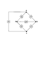
1)図1に示す6個のインピーダンス素子Z0〜Z5がブリッジ回路を構成するように結合した回路において、これらインピーダンス素子Z0〜Z5を50Ωに統一とする。このインピーダンス素子Z0〜Z5がブリッジ構成をなす回路において、インピーダンス素子Z5からみたインピーダンスは50Ωとなり、インピーダンス素子Z0からみたインピーダンスも50Ωになる。同様に、インピーダンス素子Z1、Z2、Z3からみたインピーダンスも50Ωになる。また、逆側からみたインピーダンスもそれぞれ50Ωとなる。 1) In a circuit in which the six impedance elements Z0 to Z5 shown in FIG. 1 are coupled to form a bridge circuit, the impedance elements Z0 to Z5 are unified to 50Ω. In the circuit in which the impedance elements Z0 to Z5 form a bridge configuration, the impedance viewed from the impedance element Z5 is 50Ω, and the impedance viewed from the impedance element Z0 is also 50Ω. Similarly, the impedance viewed from the impedance elements Z1, Z2, and Z3 is 50Ω. Also, the impedance viewed from the opposite side is 50Ω respectively.
2)また、図1に示すブリッジ回路において、インピーダンス素子Z5を駆動インピーダンスとし、インピーダンス素子Z0を終端インピーダンスとした場合、インピーダンス素子Z5とZ0間の電圧レベルは6dBのダウンとなり、同様に、インピーダンス素子Z5とインピーダンス素子Z1、Z2、Z3の間の分岐ロスも6dBのダウンとなる。 2) Further, in the bridge circuit shown in FIG. 1, when the impedance element Z5 is a driving impedance and the impedance element Z0 is a termination impedance, the voltage level between the impedance elements Z5 and Z0 is reduced by 6 dB. The branch loss between Z5 and the impedance elements Z1, Z2, and Z3 is also reduced by 6 dB.
3)逆に、インピーダンス素子Z0を駆動インピーダンスとし、インピーダンス素子Z5を終端インピーダンスとした場合、インピーダンス素子Z0とZ5間の電圧レベルは6dBのダウンとなり、同様に、インピーダンス素子Z1、Z2、Z3をそれぞれ駆動インピーダンスとした場合も電圧レベルは6dBのダウンが実現できる。 3) Conversely, when the impedance element Z0 is the drive impedance and the impedance element Z5 is the termination impedance, the voltage level between the impedance elements Z0 and Z5 is 6 dB down, and similarly, the impedance elements Z1, Z2, and Z3 are respectively set to Even when driving impedance is used, the voltage level can be reduced by 6 dB.
4)すなわち、図1に示すブリッジ回路において、ブリッジを構成する全てのインピーダンス素子を50Ωに統一し、ブリッジ回路の第1の中間点aとc(図1に示す対角a、c)に分岐前のインピーダンス素子Z5の一方を接続し、対角(b、d)、すなわち、第2の中間点bとd間に配置したインピーダンス素子Z4を50Ωの抵抗として終端すれば、双方向の分岐ロスが最小化された、かつ、双方向インピーダンスの整合がとれた分岐アダプタを実現することができる。すなわち、ブリッジ回路を構成する6つのインピーダンス素子のうち、ブリッジ回路がなす一方の対角を接続するインピーダンス素子(Z4)を、所定の抵抗値を有する終端抵抗とする。 4) That is, in the bridge circuit shown in FIG. 1, all impedance elements constituting the bridge are unified to 50Ω and branched to the first intermediate points a and c (diagonals a and c shown in FIG. 1) of the bridge circuit. If one of the previous impedance elements Z5 is connected and the impedance element Z4 arranged between the diagonal (b, d), that is, between the second intermediate points b and d, is terminated as a 50Ω resistor, a bidirectional branch loss Can be realized and a bi-directional impedance matching can be realized. That is, among the six impedance elements constituting the bridge circuit, the impedance element (Z4) connecting one diagonal formed by the bridge circuit is set as a termination resistor having a predetermined resistance value.
5)そして、図1に示すインピーダンス素子Z0、Z1、Z2、Z3及びZ5の代わりに、トランス素子を使用し、これら5つのトランス素子の一次側を外部機器と接続するポート(端子)として使用する。さらに、これらのトランス素子の二次側を、ブリッジ回路を構成する構成要素として使用するとともに、インピーダンス素子Z4を50Ωの抵抗として終端したブリッジを構成することにより、一次一次間、一次二次間で絶縁が確保できる分岐アダプタを実現することができる。 5) Instead of the impedance elements Z0, Z1, Z2, Z3 and Z5 shown in FIG. 1, transformer elements are used, and the primary side of these five transformer elements is used as a port (terminal) for connecting to an external device. . Furthermore, the secondary side of these transformer elements is used as a component constituting the bridge circuit, and by constructing a bridge in which the impedance element Z4 is terminated as a 50Ω resistor, between the primary and primary, between the primary and secondary A branch adapter that can ensure insulation can be realized.
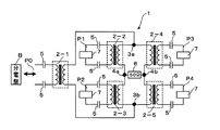
以下に、上記した技術的思想に基づいて開発した本発明の分岐アダプタについて、その実施形態を説明する。図2は、本発明の分岐アダプタについて、第1の実施形態を示す回路構成図であって、4分岐の分岐アダプタの一例を示している。 Below, the embodiment is described about the branch adapter of the present invention developed based on the above-mentioned technical idea. FIG. 2 is a circuit configuration diagram showing the first embodiment of the branch adapter of the present invention, and shows an example of a four-branch branch adapter.
(第1の実施形態)
図2は、4分岐の構成とした分岐アダプタ1の回路構成例を示している。この分岐アダプタ1は、フェライトコアから構成される高周波用小型トランス素子(以下、「トランス素子」という)の5個を、ブリッジ構成の回路を形成するように構成している。これら各トランス素子の一次側及び2次側のコイルの巻線数の比は1:1としている。また、高周波用のトランス素子であるために、その巻数は2〜4巻き程度で良い。さらに、このトランス素子の形状は1cm3程度の小型・薄型形状に製造することができる。さらに、これら複数のトランス素子を基板に配置して回路を形成することにより、一つの分岐アダプタをユニット化することができる。
(First embodiment)
FIG. 2 shows a circuit configuration example of the
図2に示す分岐アダプタ1は、5個のトランス素子(2−1)〜(2−5)を、ブリッジ構造からなる回路を形成するように接続して、4分岐の出力端子(分岐後ポート)P1〜P4を備えた構成としたものである。図2に示すように、5個のトランス素子のうち、トランス素子(2−1)の一次側をネットワークの通信線、あるいはPLC通信を用いたネットワークの場合には電力線を接続する入力側端子(以下、「分岐前ポート」という)用トランス素子としている。また、4個のトランス素子(2−2)〜(2−5)のそれぞれの一次側を外部機器となる電子機器を接続する出力端子(以下、「分岐後ポート」という)としている。これにより、分岐アダプタ1は、分岐前ポートP0がブリッジを構成する回路により4分岐された分岐後ポートP1、P2、P3、P4を備えることになる。
The
図2に示す4分岐の分岐アダプタ1の回路構成を詳細に説明すると次のようになる。
分岐前ポートとなるトランス素子(2−1)の一次側、すなわち、分岐前ポートP0は、AC100Vを供給する電力線と接続する端子になる。図2に示す例では、この分岐前ポートP0が、分電盤Bから分岐した電力線(AC100V)を接続することを示している。
The circuit configuration of the four-
The primary side of the transformer element (2-1) serving as the pre-branch port, that is, the pre-branch port P0 is a terminal connected to a power line that supplies AC 100V. In the example shown in FIG. 2, this pre-branch port P <b> 0 indicates that a power line (AC 100 V) branched from the distribution board B is connected.
そして、このトランス素子(2−1)の二次側の一つを、2つのトランス素子(2−2)とトランス素子(2−4)の二次側の一方を結ぶ導線に連結点3aとして接続する。また、トランス素子(2−1)の他の二次側を、2つのトランス素子(2−3)とトランス素子(2−5)の他方の二次側を結ぶ導線に連結点3bとして接続する。
Then, one of the secondary sides of the transformer element (2-1) is connected to a conducting wire connecting the two transformer elements (2-2) and one of the secondary sides of the transformer element (2-4) as a
さらに、トランス素子(2−2)とトランス素子(2−4)の他の二次側と、トランス素子(2−3)とトランス素子(2−5)の他の二次側とをそれぞれ連結点4a、4bとして接続するとともに、連結点4aと4bとを50Ωの抵抗6を介して接続する。また、電力線と接続するトランス素子(2−1)の一次側にはそれぞれ結合コンデンサ5を接続し、トランス素子(2−2)〜(2−5)の一次側もコンデンサ5を接続した分岐後ポートとしている。これにより、各トランス素子の二次側は、ブリッジ回路を構成する構成要素になる。
Furthermore, the other secondary side of the transformer element (2-2) and the transformer element (2-4) is connected to the other secondary side of the transformer element (2-3) and the transformer element (2-5), respectively. While connecting as
図2に示す構成の分岐アダプタ1において、トランス素子(2−1)の一次側を分岐前ポートP0として、AC100Vを供給する電力線と接続しても、結合コンデンサ5によりAC100Vはカットされて伝送データとなる高周波信号のみが分岐アダプタ1を構成する回路内を流れる。これにより、分岐アダプタ1はAC100Vに接続可能な分岐アダプタとすることができる。
In the
さらに、ブリッジ構成となるように5つのトランス素子(2−1)〜(2−5)を接続しているので、分岐アダプタ1を構成する各トランス素子の一次側は、いずれも上り方向及び下り方向からみてもインピーダンスが同一、すなわち、伝送路の下り及び上り方向の双方においてインピーダンスの整合をとることができる。また、ブリッジ構成により、伝送路を4つに分岐しても分岐におるロスを最小化させることが可能になる。さらに、各トランス素子(2−1)〜(2−5)の一次側に結合コンデンサ5を接続し、これら一次側に外部機器7を接続する構成としているので、トランス素子の一次二次間の絶縁と、分岐アダプタ1の耐圧を確保することが可能になる。
Further, since the five transformer elements (2-1) to (2-5) are connected so as to form a bridge configuration, the primary side of each transformer element constituting the
図3は、図2に示す分岐アダプタ1において、トランス素子(2−2)〜(2−5)の一次側のいずれかの分岐後ポートP1〜P4、例えばトランス素子(2−5)(ポートP4)に電子機器7を接続する必要がない場合に、トランス素子(2−5)の一次側に50Ωの終端抵抗8を接続して上記したインピーダンスの整合をとるようにした例を示している。このように、電子機器7を接続しない分岐後ポートP1〜P4の何れかには、50Ωの終端抵抗8を接続することにより、図2に示す4分岐の分岐アダプタ1は、2又は3分岐の分岐アダプタとして使用することができる。また、50Ωの終端抵抗を実際に接続する場合には、外部機器との接続を考慮して後述する図5に示すような構成にするとよい。
FIG. 3 shows the branching
(第2の実施形態)
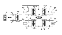
続いて、本発明に係る分岐アダプタの第2の実施形態を、図4に基づいて説明する。図4は、16分岐とした分岐アダプタ11の回路構成例を示している。この16分岐の分岐アダプタ11は、図2に示すブリッジ構造からなる回路を一つのユニットとして、このユニットの4つを、さらにブリッジ構造を形成するように配置することにより、16分岐の分岐アダプタとしたものである。
(Second Embodiment)
Next, a second embodiment of the branch adapter according to the present invention will be described with reference to FIG. FIG. 4 shows a circuit configuration example of the
図4に示す16分岐の分岐アダプタ11は、図1に示すブリッジ構成をなす4つの高周波トランス素子(2−2)〜(2−5)を一つのブリッジ構成パターン(図4に示すパターンA1、A2、A3、A4)とし、このブリッジ構成パターンの4つが、さらにブリッジ構成をなすように配置した回路構成とすることにより、16個の分岐後ポートP1〜P16が形成されるようにしたものである。すなわち、図4に示すように、1個の高周波トランス素子(2−1)を分岐前用トランスとしてその一次側を分岐前ポートP0とし、16個の高周波トランス素子(2−2)〜(2−17)の一次側を分岐後ポートP1〜P16として、計16個の分岐後ポートを備えた回路構成としたものである。
The
図4に示す16分岐の分岐アダプタ11について、その回路構成の詳細を説明すると次のようになる。
1)ブリッジ構成パターンA1を構成するトランス素子(2−2)と(2−4)の二次側の一方どうしを導線で接続する。同様に、ブリッジ構成パターンA2を構成するトランス素子(2−10)と(2−12)の二次側の一方どうしを接続するとともに、これら接続した導線の連結点(3a−1)と(3a−2)を導線9aにより接続する。
The details of the circuit configuration of the 16-
1) One side of the secondary side of the transformer elements (2-2) and (2-4) constituting the bridge configuration pattern A1 is connected by a conducting wire. Similarly, one of the secondary elements of the transformer elements (2-10) and (2-12) constituting the bridge configuration pattern A2 is connected to each other, and connection points (3a-1) and (3a) of these connected conductors are connected. -2) is connected by the
2)ブリッジ構成パターンA3とA4についても、上記1)と同様に、連結点3b−3と3b−4を設けて、これら連結点(3b−3)と(3b−4)を導線9bにより接続する。
2) Similarly to the above 1), the connection points 3b-3 and 3b-4 are provided for the bridge configuration patterns A3 and A4, and these connection points (3b-3) and (3b-4) are connected by the
3)ブリッジ構成パターンA1を構成するトランス素子(2−3)と(2−5)の二次側の一方どうしを導線で接続する。同様に、ブリッジ構成パターンA3を構成するトランス素子(2−6)と(2−8)の二次側の一方どうしを接続するとともに、これら接続した導線の連結点(3b−2)と(3a−3)を導線9cにより接続する。
3) One of the secondary sides of the transformer elements (2-3) and (2-5) constituting the bridge configuration pattern A1 is connected by a conducting wire. Similarly, one of the secondary elements of the transformer elements (2-6) and (2-8) constituting the bridge configuration pattern A3 is connected to each other, and connection points (3b-2) and (3a) of these connected conductors are connected. -3) is connected by the
4)ブリッジ構成パターンA2を構成するトランス素子(2−11)と(2−13)の二次側の一方どうしを導線で接続する。同様に、ブリッジ構成パターンA4を構成するトランス素子(2−14)と(2−16)の二次側の一方どうしを接続するとともに、これら接続した導線の連結点(3b−2)と(3a−4)を導線9dにより接続する。
4) The transformer elements (2-11) and (2-13) constituting the bridge configuration pattern A2 are connected to each other on the secondary side with a conductive wire. Similarly, one of the secondary elements of the transformer elements (2-14) and (2-16) constituting the bridge configuration pattern A4 is connected to each other, and connection points (3b-2) and (3a) of these connected conductors are connected. -4) is connected by the
5)導線9cと9dとを50Ωの抵抗6を介して接続する。
6)分岐アダプタ11の入力端子(分岐前ポート)P0として配置したトランス素子(2−1)の二次側の一方を導線9aに、同じく二次側の他方を導線9bに接続する。
7)4つのブリッジ構成パターンA1とA2とA3とA4を構成する各高周波トランス素子(2−2)〜(2−17)の一次側にはコンデンサ5を接続する。
5) The
6) One of the secondary sides of the transformer element (2-1) arranged as the input terminal (pre-branch port) P0 of the
7) A
そして、他の回路構成は、図2に示す4分岐の分岐アダプタ1の構成と同じ構成にする。例えば、ブリッジ構成パターンA1において、トランス素子(2−2)と(2−3)の二次側の一方どうしを接続し、同様にトランス素子(2−4)と(2−5)の二次側の一方どうしを接続する。そして、これらの接続点4aと4bを50Ωの抵抗6を介して接続する。
The other circuit configuration is the same as that of the 4-
上記した回路構成からなる16分岐の分岐アダプタ11において、4つのブリッジ構成パターンA1、A2、A3、A4を構成するトランス素子(2−2)〜(2−17)の16個の一次側を分岐後ポートとして、外部機器7を接続する。また、分岐アダプタ11の分岐前ポートとなるトランス素子(2−1)の一次側には、電力線又は通信線が接続される。
In the 16-
図4に示す16分岐の分岐アダプタ11においても、分岐後ポートに外部機器7を接続しない場合には、図3に示したように、使用しない分岐後ポートのトランス素子の一次側に50Ωの終端抵抗8を接続して、インピーダンスの整合をとるようにする。これにより、 図4に示す分岐アダプタ11は、最大16個の分岐後ポートを備えた分岐アダプタとして使用することができる。
Also in the 16-
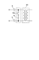
図5は、図2及び図4に示す各トランス素子に、自動又は手動で終端抵抗を作動させるスイッチ手段を設けたトランス素子20の構成例を示している。図5に示すトランス素子20は、その一次側の端子間にスイッチSwと50Ωの終端抵抗8を直列に接続した構成を示している。そして、このトランス素子20の一次側を分岐後ポートとして使用する場合には、手動操作によりスイッチSwを「開(開放:OFF)」にして終端抵抗8が作動しないようにする。一方、トランス素子20の一次側を分岐後ポートとして使用しない場合には、手動操作によりスイッチSwを「閉(ON)」にして終端抵抗8が作動するようにする。また、スイッチSwの開閉は、フォットリレー等を使用して、電子機器が接続されているときにはスイッチSwを自動的に「開」とし、電子機器が接続されていないときにはスイッチSwを自動的に「閉(ON)」とする制御を行なうことができる。
FIG. 5 shows a configuration example of the
上記した本発明の分岐アダプタに係る第1の実施形態は4分岐、第2の実施形態は16分岐の分岐後ポートを備えている。そして、分岐後ポートには上記したスイッチ手段を設けているので、ネットワークに接続されている電子機器等の端末装置の設置台数などに対応させて、この分岐後ポートを有効なポートとして使用することができる。なお、本発明の分岐アダプタの製作は、5個又は17個の高周波トランスが図2又は図4に示すようなブリッジ回路をなす配線パターンを基板に形成し、この基板にこれらトランスと、結合コンデンサと、インピーダンス(抵抗)と、分岐前ポート及び分岐後ポートとなるモジューラジャック、スイッチ手段等、及びAC100V用端子等を固定する。そして、この基板を合成樹脂製の筐体に収納して固定するようにする。 The first embodiment according to the above-described branch adapter of the present invention includes a post-branch port of 4 branches and the second embodiment of 16 branches. Since the above-mentioned switch means is provided in the post-branch port, the post-branch port should be used as an effective port according to the number of terminal devices such as electronic devices connected to the network. Can do. The branch adapter according to the present invention is manufactured by forming a wiring pattern in which five or seventeen high-frequency transformers form a bridge circuit as shown in FIG. 2 or FIG. Then, the impedance (resistance), the modular jack, the switch means, etc., and the AC100V terminal, etc., which are the pre-branch port and post-branch port are fixed. Then, the substrate is housed and fixed in a synthetic resin casing.
また、本発明の分岐アダプタは、高周波トランス素子を、ブリッジ構成の回路を形成するように、またこのブリッジ構成の回路が多重構造となるように接続した構成を備え、さらに、一次側に結合コンデンサを接続するとともに、ブリッジ構成の回路に50Ωのインピーダンス素子を備えているので、伝送路における高周波信号の分岐ロスを最小化することができ、さらに、伝送路の双方向のインピーダンス整合をとることができる分岐アダプタを提供することができる。これにより本発明は、特に、電力線を使用した通信を行なうPLC通信のネットワークシステムにおいて、その伝送路を多数に分岐するアダプタとして使用すると、その効果は大になる。 The branch adapter according to the present invention has a configuration in which high-frequency transformer elements are connected so as to form a bridge-structured circuit, and the bridge-structured circuit has a multiple structure, and a coupling capacitor is provided on the primary side. In addition, the bridge-structured circuit is equipped with a 50Ω impedance element, so that it is possible to minimize the branch loss of the high-frequency signal in the transmission line, and to achieve bidirectional impedance matching of the transmission line. A branch adapter that can be provided can be provided. As a result, the present invention is particularly effective when used as an adapter for branching the transmission path into a large number in a PLC communication network system that performs communication using a power line.
1 :分岐アダプタ(4分岐の分岐アダプタ)
2−1、2−2、・・・・、2−17:高周波トランス素子
5 :結合コンデンサ
6 :抵抗
7 :電子機器(外部機器)
8 :終端抵抗
11:分岐アダプタ(16分岐の分岐アダプタ)
A1、A2.A3.A4:ブリッジ構成パターン
P0:分岐前ポート(入力端子:接続ポート)
P1、P2、P3、・・・、P16:分岐後ポート(出力端子:接続ポート)
Sw:スイッチ手段
1: Branch adapter (branch adapter with 4 branches)
2-17: High frequency transformer element 5: Coupling capacitor 6: Resistance 7: Electronic device (external device)
8: Termination resistor 11: Branch adapter (branch adapter with 16 branches)
A1, A2. A3. A4: Bridge configuration pattern P0: Port before branch (input terminal: connection port)
P1, P2, P3,..., P16: Port after branching (output terminal: connection port)
Sw: Switch means
Claims (6)
前記ブリッジを構成する4個のインピーダンス素子を4個のトランス素子により構成するとともに、各トランスの二次側を接続することにより前記ブリッジを構成し、
前記一方の対角に接続される1個のインピーダンス素子をトランス素子により構成するとともに、当該トランス素子の二次側を前記ブリッジの一方の対角に接続し、
前記他方の対角に接続される1個のインピーダンス素子を抵抗により構成し、
前記一方の対角に接続されるトランス素子の一次側を伝送データとなる高周波信号が入力される入力端子とするとともに、前記ブリッジを構成する4個のトランス素子各々の一次側を外部機器が接続される出力端子とした、
ことを特徴とする分岐アダプタ。 A bridge circuit in which one impedance element is connected to one diagonal of a bridge constituted by four impedance elements, and one impedance element is connected to the other diagonal ;
The four impedance elements constituting the bridge are constituted by four transformer elements, and the bridge is constituted by connecting the secondary side of each transformer,
One impedance element connected to the one diagonal is constituted by a transformer element, and the secondary side of the transformer element is connected to one diagonal of the bridge,
One impedance element connected to the other diagonal is constituted by a resistor,
The primary side of the transformer element connected to the one diagonal is used as an input terminal for inputting a high-frequency signal as transmission data, and an external device is connected to the primary side of each of the four transformer elements constituting the bridge. Output terminal,
Branch adapter characterized by that.
一次側を伝送データとなる高周波信号が入力される入力端子とした分岐前ポート用トランス素子を備え、
前記分岐前ポート用トランス素子の二次側の一方を前記二つのトランス素子の二次側の一方どうしを接続した一方の接続部に接続し、前記分岐前ポート用トランス素子の二次側の他方を前記二つのトランス素子の二次側の一方どうしを接続した他方の接続部に接続した構成からなり、
前記4個のトランス素子の一次側を、外部機器が接続される出力端子である分岐後ポートとした、
ことを特徴とする分岐アダプタ。 For two sets of two transformer elements connected to one of the secondary sides of the transformer elements, the other secondary sides of the transformer elements of each set are connected to each other, and the connected secondary sides are connected to each other. A circuit having a combination of four transformer elements connected via a resistor;
A pre-branch port transformer element having the primary side as an input terminal to which a high-frequency signal serving as transmission data is input,
One of the secondary sides of the transformer element for the pre-branch port is connected to one connecting portion connecting one of the secondary sides of the two transformer elements, and the other of the secondary side of the transformer element for the branch port the result from the configuration connected to the other connection portion connecting the hand each other on the secondary side of the two transformers element,
The primary side of the four transformer elements is a post-branching port that is an output terminal to which an external device is connected.
Branch adapter characterized by that.
一次側を伝送データとなる高周波信号が入力される入力端子とした分岐前ポート用トランス素子と、を備え、
前記ブリッジ1と前記ブリッジ2の前記抵抗を介して接続された二次側ではない一方の二次側どうしを接続するとともに、前記分岐前ポート用トランス素子の二次側の一方に接続し、
前記ブリッジ3と前記ブリッジ4の前記抵抗を介して接続された二次側ではない一方の二次側どうしを接続するとともに、前記分岐前ポート用トランス素子の二次側の他方に接続し、
前記ブリッジ1と前記ブリッジ3の前記抵抗を介して接続された二次側ではない他方の二次側どうしを接続(以下、ブリッジ1−3間という)し、前記ブリッジ2と前記ブリッジ4の前記抵抗を介して接続された二次側ではない他方の二次側どうしを接続する(以下、ブリッジ2−4間という)とともに、前記ブリッジ1−3間と前記ブリッジ2−4間とを抵抗を介して接続し、
前記ブリッジ1および、前記ブリッジ2および、前記ブリッジ3および、前記ブリッジ4を構成する16個のトランス素子の一次側を、外部機器が接続される出力端子である分岐後ポートとした、
ことを特徴とする分岐アダプタ。 For two sets of two transformer elements connected to one of the secondary sides of the transformer elements, the other secondary sides of the transformer elements of each set are connected to each other, and the connected secondary sides are connected to each other. , A bridge configuration having a combination of four transformer elements connected via a resistor, a bridge 2, a bridge 3, a bridge 4, and
A pre-branch port transformer element having a primary side as an input terminal to which a high-frequency signal serving as transmission data is input,
Connecting one secondary side that is not the secondary side connected via the resistor of the bridge 1 and the bridge 2 to each other and one secondary side of the transformer element for the port before branching;
Connecting one secondary side which is not the secondary side connected via the resistor of the bridge 3 and the bridge 4 to each other, and connecting to the other secondary side of the transformer element for the pre-branch port,
The bridge 1 and the said connection and the other secondary-side each other not via a resistor connected secondary side of the bridge 3 (hereinafter, referred to as between the bridge 1-3) and the of the bridge 2 and the bridge 4 The other secondary side that is not the secondary side connected through a resistor is connected to each other (hereinafter referred to as between the bridges 2-4), and the resistance between the bridge 1-3 and the bridge 2-4 is reduced. Connect through
The primary side of the 16 transformer elements constituting the bridge 1, the bridge 2, the bridge 3, and the bridge 4 is a post-branch port that is an output terminal to which an external device is connected.
Branch adapter characterized by that.
Priority Applications (1)
| Application Number | Priority Date | Filing Date | Title |
|---|---|---|---|
| JP2008188873A JP5380010B2 (en) | 2008-07-22 | 2008-07-22 | Branch adapter |
Applications Claiming Priority (1)
| Application Number | Priority Date | Filing Date | Title |
|---|---|---|---|
| JP2008188873A JP5380010B2 (en) | 2008-07-22 | 2008-07-22 | Branch adapter |
Publications (2)
| Publication Number | Publication Date |
|---|---|
| JP2010028564A JP2010028564A (en) | 2010-02-04 |
| JP5380010B2 true JP5380010B2 (en) | 2014-01-08 |
Family
ID=41733949
Family Applications (1)
| Application Number | Title | Priority Date | Filing Date |
|---|---|---|---|
| JP2008188873A Expired - Fee Related JP5380010B2 (en) | 2008-07-22 | 2008-07-22 | Branch adapter |
Country Status (1)
| Country | Link |
|---|---|
| JP (1) | JP5380010B2 (en) |
Family Cites Families (1)
| Publication number | Priority date | Publication date | Assignee | Title |
|---|---|---|---|---|
| JPH1065477A (en) * | 1996-08-23 | 1998-03-06 | Nikou Denki Kogyo Kk | Branching device |
-
2008
- 2008-07-22 JP JP2008188873A patent/JP5380010B2/en not_active Expired - Fee Related
Also Published As
| Publication number | Publication date |
|---|---|
| JP2010028564A (en) | 2010-02-04 |
Similar Documents
| Publication | Publication Date | Title |
|---|---|---|
| JP6370989B2 (en) | Power over Ethernet (registered trademark) for 10GBASE-T Ethernet (registered trademark) | |
| CN110277920B (en) | Power and communication system for providing differential data and DC power on line pairs | |
| JP2004517545A5 (en) | ||
| JPH0225296B2 (en) | ||
| CN103873262B (en) | coaxial cable power supply system | |
| KR20130107290A (en) | Lcl high power combiner | |
| BE1024223B1 (en) | Cable tap | |
| EP1959525B1 (en) | Connector including isolation of magnetic devices capable of handling high speed communications | |
| US10509453B2 (en) | Electronic communications device, particularly Power-over-Ethernet terminal, as well as add-on board | |
| US8097973B2 (en) | Power mains transformer data bridge | |
| JP5380010B2 (en) | Branch adapter | |
| CN101911481A (en) | Signal splitter | |
| CN108600058A (en) | A kind of ethernet signal transmission interface circuit and the network equipment | |
| AU2016207976B2 (en) | Systems and methods for enhanced high frequency power bias tee designs | |
| JP2018129760A (en) | Power distribution system | |
| EP1603249A1 (en) | High frequency bypass unit | |
| CN102446616B (en) | Filter circuit and electrical connector with the filter circuit | |
| CN101430968A (en) | Single-phase traction transformer used for AT power supply mode high speed passenger dedicated railway | |
| JP2017535189A (en) | Spur insulation in fieldbus networks | |
| CN101662108A (en) | Electric connector | |
| CN109103606A (en) | Antenna system and mobile terminal | |
| CN206894250U (en) | A kind of strong and weak electricity isolating device | |
| CN101006627A (en) | Electric energy transmitting device with a phase conductor and an screen conductor | |
| CN201387800Y (en) | Transformer | |
| CN220474453U (en) | A variable voltage transformer |
Legal Events
| Date | Code | Title | Description |
|---|---|---|---|
| RD02 | Notification of acceptance of power of attorney |
Free format text: JAPANESE INTERMEDIATE CODE: A7422 Effective date: 20101229 |
|
| A621 | Written request for application examination |
Free format text: JAPANESE INTERMEDIATE CODE: A621 Effective date: 20110518 |
|
| A131 | Notification of reasons for refusal |
Free format text: JAPANESE INTERMEDIATE CODE: A131 Effective date: 20120925 |
|
| A521 | Written amendment |
Free format text: JAPANESE INTERMEDIATE CODE: A523 Effective date: 20121126 |
|
| A131 | Notification of reasons for refusal |
Free format text: JAPANESE INTERMEDIATE CODE: A131 Effective date: 20130621 |
|
| A521 | Written amendment |
Free format text: JAPANESE INTERMEDIATE CODE: A523 Effective date: 20130807 |
|
| TRDD | Decision of grant or rejection written | ||
| A01 | Written decision to grant a patent or to grant a registration (utility model) |
Free format text: JAPANESE INTERMEDIATE CODE: A01 Effective date: 20130903 |
|
| A61 | First payment of annual fees (during grant procedure) |
Free format text: JAPANESE INTERMEDIATE CODE: A61 Effective date: 20130930 |
|
| R150 | Certificate of patent or registration of utility model |
Ref document number: 5380010 Country of ref document: JP Free format text: JAPANESE INTERMEDIATE CODE: R150 Free format text: JAPANESE INTERMEDIATE CODE: R150 |
|
| R250 | Receipt of annual fees |
Free format text: JAPANESE INTERMEDIATE CODE: R250 |
|
| LAPS | Cancellation because of no payment of annual fees |