JP5379842B2 - Recording apparatus and determination method thereof - Google Patents
Recording apparatus and determination method thereof Download PDFInfo
- Publication number
- JP5379842B2 JP5379842B2 JP2011272752A JP2011272752A JP5379842B2 JP 5379842 B2 JP5379842 B2 JP 5379842B2 JP 2011272752 A JP2011272752 A JP 2011272752A JP 2011272752 A JP2011272752 A JP 2011272752A JP 5379842 B2 JP5379842 B2 JP 5379842B2
- Authority
- JP
- Japan
- Prior art keywords
- recording element
- recording
- element substrate
- temperature
- temperature sensor
- Prior art date
- Legal status (The legal status is an assumption and is not a legal conclusion. Google has not performed a legal analysis and makes no representation as to the accuracy of the status listed.)
- Expired - Fee Related
Links
Images


Classifications
-
- B—PERFORMING OPERATIONS; TRANSPORTING
- B41—PRINTING; LINING MACHINES; TYPEWRITERS; STAMPS
- B41J—TYPEWRITERS; SELECTIVE PRINTING MECHANISMS, i.e. MECHANISMS PRINTING OTHERWISE THAN FROM A FORME; CORRECTION OF TYPOGRAPHICAL ERRORS
- B41J2/00—Typewriters or selective printing mechanisms characterised by the printing or marking process for which they are designed
- B41J2/005—Typewriters or selective printing mechanisms characterised by the printing or marking process for which they are designed characterised by bringing liquid or particles selectively into contact with a printing material
- B41J2/01—Ink jet
- B41J2/015—Ink jet characterised by the jet generation process
- B41J2/04—Ink jet characterised by the jet generation process generating single droplets or particles on demand
- B41J2/045—Ink jet characterised by the jet generation process generating single droplets or particles on demand by pressure, e.g. electromechanical transducers
- B41J2/04501—Control methods or devices therefor, e.g. driver circuits, control circuits
- B41J2/0458—Control methods or devices therefor, e.g. driver circuits, control circuits controlling heads based on heating elements forming bubbles
-
- B—PERFORMING OPERATIONS; TRANSPORTING
- B41—PRINTING; LINING MACHINES; TYPEWRITERS; STAMPS
- B41J—TYPEWRITERS; SELECTIVE PRINTING MECHANISMS, i.e. MECHANISMS PRINTING OTHERWISE THAN FROM A FORME; CORRECTION OF TYPOGRAPHICAL ERRORS
- B41J2/00—Typewriters or selective printing mechanisms characterised by the printing or marking process for which they are designed
- B41J2/005—Typewriters or selective printing mechanisms characterised by the printing or marking process for which they are designed characterised by bringing liquid or particles selectively into contact with a printing material
- B41J2/01—Ink jet
- B41J2/015—Ink jet characterised by the jet generation process
- B41J2/04—Ink jet characterised by the jet generation process generating single droplets or particles on demand
- B41J2/045—Ink jet characterised by the jet generation process generating single droplets or particles on demand by pressure, e.g. electromechanical transducers
- B41J2/04501—Control methods or devices therefor, e.g. driver circuits, control circuits
- B41J2/0451—Control methods or devices therefor, e.g. driver circuits, control circuits for detecting failure, e.g. clogging, malfunctioning actuator
-
- B—PERFORMING OPERATIONS; TRANSPORTING
- B41—PRINTING; LINING MACHINES; TYPEWRITERS; STAMPS
- B41J—TYPEWRITERS; SELECTIVE PRINTING MECHANISMS, i.e. MECHANISMS PRINTING OTHERWISE THAN FROM A FORME; CORRECTION OF TYPOGRAPHICAL ERRORS
- B41J2/00—Typewriters or selective printing mechanisms characterised by the printing or marking process for which they are designed
- B41J2/005—Typewriters or selective printing mechanisms characterised by the printing or marking process for which they are designed characterised by bringing liquid or particles selectively into contact with a printing material
- B41J2/01—Ink jet
- B41J2/015—Ink jet characterised by the jet generation process
- B41J2/04—Ink jet characterised by the jet generation process generating single droplets or particles on demand
- B41J2/045—Ink jet characterised by the jet generation process generating single droplets or particles on demand by pressure, e.g. electromechanical transducers
- B41J2/04501—Control methods or devices therefor, e.g. driver circuits, control circuits
- B41J2/04563—Control methods or devices therefor, e.g. driver circuits, control circuits detecting head temperature; Ink temperature
-
- B—PERFORMING OPERATIONS; TRANSPORTING
- B41—PRINTING; LINING MACHINES; TYPEWRITERS; STAMPS
- B41J—TYPEWRITERS; SELECTIVE PRINTING MECHANISMS, i.e. MECHANISMS PRINTING OTHERWISE THAN FROM A FORME; CORRECTION OF TYPOGRAPHICAL ERRORS
- B41J2/00—Typewriters or selective printing mechanisms characterised by the printing or marking process for which they are designed
- B41J2/005—Typewriters or selective printing mechanisms characterised by the printing or marking process for which they are designed characterised by bringing liquid or particles selectively into contact with a printing material
- B41J2/01—Ink jet
- B41J2/135—Nozzles
- B41J2/145—Arrangement thereof
- B41J2/155—Arrangement thereof for line printing
-
- B—PERFORMING OPERATIONS; TRANSPORTING
- B41—PRINTING; LINING MACHINES; TYPEWRITERS; STAMPS
- B41J—TYPEWRITERS; SELECTIVE PRINTING MECHANISMS, i.e. MECHANISMS PRINTING OTHERWISE THAN FROM A FORME; CORRECTION OF TYPOGRAPHICAL ERRORS
- B41J2/00—Typewriters or selective printing mechanisms characterised by the printing or marking process for which they are designed
- B41J2/005—Typewriters or selective printing mechanisms characterised by the printing or marking process for which they are designed characterised by bringing liquid or particles selectively into contact with a printing material
- B41J2/01—Ink jet
- B41J2/135—Nozzles
- B41J2/14—Structure thereof only for on-demand ink jet heads
- B41J2002/14491—Electrical connection
-
- B—PERFORMING OPERATIONS; TRANSPORTING
- B41—PRINTING; LINING MACHINES; TYPEWRITERS; STAMPS
- B41J—TYPEWRITERS; SELECTIVE PRINTING MECHANISMS, i.e. MECHANISMS PRINTING OTHERWISE THAN FROM A FORME; CORRECTION OF TYPOGRAPHICAL ERRORS
- B41J2202/00—Embodiments of or processes related to ink-jet or thermal heads
- B41J2202/01—Embodiments of or processes related to ink-jet heads
- B41J2202/20—Modules
Landscapes
- Ink Jet (AREA)
Abstract
Description
本発明は、記録装置及びその判定方法に関する。 The present invention relates to a recording apparatus and a determination method thereof.
従来、温度センサやヒータ(記録素子)を有する基板(記録素子基板)が複数設けられた記録ヘッドを備えた記録装置が知られている。このような記録ヘッドを備えた記録装置においては、複数の基板それぞれに設けられた温度センサを用いて各基板の温度を選択的に検知し、複数の基板のそれぞれに備わるヒータを選択的に動作させて温度制御を行なう技術が知られている(特許文献1)。 2. Description of the Related Art Conventionally, a recording apparatus having a recording head provided with a plurality of substrates (recording element substrates) having temperature sensors and heaters (recording elements) is known. In a recording apparatus having such a recording head, the temperature of each substrate is selectively detected using temperature sensors provided on each of the plurality of substrates, and the heaters provided on each of the plurality of substrates are selectively operated. A technique for controlling the temperature is known (Patent Document 1).
また、ヒータの駆動前後の温度変化に基づいて温度センサ及びヒータの双方が正常に動作しているか否かを判定し、少なくとも一方に異常があれば、記録処理を制限する技術が知られている(特許文献2)。 Further, a technique is known in which it is determined whether or not both the temperature sensor and the heater are operating normally based on a temperature change before and after the heater is driven, and if at least one is abnormal, the recording process is limited. (Patent Document 2).
従来、複数の基板それぞれに設けられた温度センサからの検出信号を選択的に取得する手法は知られている。しかし、基板(例えば、温度センサ、ヒータ及び駆動回路、選択回路等)の異常を判定する際に、例えば、複数の基板それぞれに設けられた温度センサの検出信号を選択する選択回路等に異常があった場合、見掛け上、正常であると誤った判定をしてしまう場合があった。 Conventionally, a technique for selectively acquiring detection signals from temperature sensors provided on a plurality of substrates is known. However, when determining an abnormality of a substrate (for example, a temperature sensor, a heater and drive circuit, a selection circuit, etc.), for example, an abnormality is detected in a selection circuit that selects a detection signal of a temperature sensor provided on each of a plurality of substrates If so, it may have been erroneously determined to be normal.
そこで、本発明は、上記課題に鑑みてなされたものであり、記録素子基板の状態判定の信頼性を向上させるようにした技術を提供することを目的とする。 Accordingly, the present invention has been made in view of the above problems, and an object of the present invention is to provide a technique for improving the reliability of the state determination of the recording element substrate.
上記課題を解決するため、本発明の一態様による記録装置は、熱エネルギーを利用してインクを吐出する複数の記録素子を備え、前記記録素子の配列方向に沿って配置された複数の記録素子基板と、前記複数の記録素子基板のそれぞれに対応して設けられ、当該記録素子基板の温度を測定する温度センサと、複数の前記温度センサのいずれか1つを選択する選択手段と、を備える記録装置であって、前記複数の記録素子基板のうち、前記選択手段によって選択された前記温度センサが設けられた記録素子基板における前記記録素子のみを駆動したときに当該温度センサによって測定される温度に基づいて、当該記録素子基板の異常の有無を判定する判定動作を行う判定手段を備え、前記判定手段は、ある記録素子基板に対する前記判定動作を行った後に、当該判定動作を行った記録素子基板に隣接しない記録素子基板に対する前記判定動作を次に行う。 In order to solve the above-described problem, a recording apparatus according to an aspect of the present invention includes a plurality of recording elements that eject ink using thermal energy, and are arranged along the arrangement direction of the recording elements. comprising a substrate, provided corresponding to each of the plurality of recording element substrates, a temperature sensor for measuring the temperature of the recording element substrate, and selection means for selecting one of a plurality of the temperature sensors, the a recording apparatus measurement among the plurality of recording element substrates, by the temperature sensor when the temperature sensor chosen by the selection means is driven only the recording elements in the recording element substrate provided and based on the temperatures comprises determining means for determining operation of determining the presence or absence of the recording element substrate abnormality, the determination means, the determination operation for a recording element substrate After Tsu, then performs the determination operation for the recording element substrate which is not adjacent to the recording element substrate subjected to the determination operation.
本発明によれば、記録素子基板の状態判定の信頼性を向上させられる。 According to the present invention, the reliability of the state determination of the recording element substrate can be improved.
以下、図面を参照して本発明の好適な実施形態について詳細に説明する。以下の説明においては、インクジェット記録方式を用いた記録装置を例に挙げて説明する。記録装置は、例えば、記録機能のみを有するシングルファンクションプリンタであってもよいし、また、例えば、記録機能、FAX機能、スキャナ機能等の複数の機能を有するマルチファンクションプリンタであってもよい。また、例えば、カラーフィルタ、電子デバイス、光学デバイス、微小構造物等を所定の記録方式で製造するための製造装置であってもよい。 DESCRIPTION OF EMBODIMENTS Hereinafter, preferred embodiments of the present invention will be described in detail with reference to the drawings. In the following description, a recording apparatus using an ink jet recording method will be described as an example. The recording apparatus may be, for example, a single function printer having only a recording function, or may be, for example, a multi-function printer having a plurality of functions such as a recording function, a FAX function, and a scanner function. In addition, for example, a manufacturing apparatus for manufacturing a color filter, an electronic device, an optical device, a minute structure, and the like by a predetermined recording method may be used.
なお、以下の説明において、「記録」とは、文字、図形等有意の情報を形成する場合のみならず、有意無意を問わない。更に人間が視覚で知覚し得るように顕在化したものであるか否かも問わず、広く記録媒体上に画像、模様、パターン、構造物等を形成する、又は媒体の加工を行なう場合も表す。 In the following description, “recording” is not limited to the case where significant information such as characters and figures is formed, and it does not matter whether it is significant. Further, it also represents a case where an image, a pattern, a pattern, a structure, or the like is widely formed on a recording medium or a medium is processed regardless of whether or not it is manifested so that a human can perceive it visually.
また、「記録媒体」とは、一般的な記録装置で用いられる紙のみならず、布、プラスチック・フィルム、金属板、ガラス、セラミックス、樹脂、木材、皮革等、インクを受容可能なものも表す。 “Recording medium” represents not only paper used in general recording apparatuses but also cloth, plastic film, metal plate, glass, ceramics, resin, wood, leather, and the like that can accept ink. .
更に、「インク」とは、上記「記録」の定義と同様広く解釈されるべきものである。従って、記録媒体上に付与されることによって、画像、模様、パターン等の形成又は記録媒体の加工、或いはインクの処理(例えば、記録媒体に付与されるインク中の色剤の凝固または不溶化)に供され得る液体を表す。 Further, “ink” should be interpreted widely as in the definition of “recording”. Therefore, by being applied on the recording medium, it can be used for forming an image, pattern, pattern, etc., processing the recording medium, or processing the ink (for example, coagulation or insolubilization of the colorant in the ink applied to the recording medium). Represents a liquid that can be provided.
(実施形態1)
図1は、本発明の一実施の形態に係わるインクジェット記録装置(以下、記録装置と呼ぶ)1の構成の一例を示す図である。
(Embodiment 1)
FIG. 1 is a diagram showing an example of the configuration of an ink jet recording apparatus (hereinafter referred to as a recording apparatus) 1 according to an embodiment of the present invention.
記録装置1には、記録媒体の幅に相当する記録幅を持つ、いわゆる、フルラインタイプの記録ヘッド2が設けられる。記録ヘッド2は、各色(2Y,2M,2C,2Bk)に対応して複数設けられる。具体的には、イエローインクを吐出する記録ヘッド2Yと、マゼンタインクを吐出する記録ヘッド2Mと、シアンインクを吐出する記録ヘッド2Cと、ブラックインクを吐出する記録ヘッド2Bkとが設けられる。これら記録ヘッド各々は、図2に示すように、記録媒体Pの搬送方向(走査方向:X方向)と直交する方向(ノズル配列方向:Y方向)に延在して設けられる。
The recording apparatus 1 is provided with a so-called full line
各記録ヘッド2は、イエローインク、マゼンタインク、シアンインク、ブラックインクをそれぞれ貯留する4つのインクタンク3Y、3M、3C、3Bk(以下、これらをまとめてインクタンク3と呼ぶ)に対して接続配管4を介して接続される。各インクタンク3は、それぞれ独立して着脱できる。
Each
記録ヘッド2は、搬送用ベルト5を挟んでプラテン6と対向する位置に設けられる。記録ヘッド2は、ヘッド移動部10によりプラテン6との対向方向に昇降させられる。なお、ヘッド移動部10は、制御部9によりその作動が制御される。
The
また、記録ヘッド2には、インクを吐出するインク吐出口と、インクタンク3のインクが供給される共通液室と、この共通液室から各インク吐出口へとインクを導くインク流路(ノズル)とが設けられる。各ノズルには、例えば、発熱抵抗素子から構成される記録素子(以下、ヒータ呼ぶ場合もある)やヒータ駆動回路等が設けられる。
The
すなわち、本実施形態に係わる記録ヘッド2は、熱エネルギーを利用してインクを吐出するインクジェット方式が採用されており、熱エネルギーを発生するために発熱抵抗素子が設けられる。これにより、発熱抵抗素子の熱エネルギーによりインクに膜沸騰を生じさせ、吐出口よりインクを吐出する。発熱抵抗素子は、各吐出口のそれぞれに対応して設けられ、記録信号に応じて対応する発熱抵抗素子に電圧のパルスを印加することによって対応する吐出口からインクが吐出される。
In other words, the
ここで、ヒータは、ヘッドドライバ2aを介して制御部9に電気的に接続されており、制御部9から送られてくるオン/オフ信号(吐出/不吐出信号)に応じてヒータの駆動、停止が制御される。
Here, the heater is electrically connected to the
制御部9は、記録装置1における各種処理を統括制御する。制御部9は、例えば、CPU(Central Processing Unit)、ROMやRAM等のメモリ等、ASIC(ApplicationSpecific Integrated Circuit)等で構成される。
The
記録ヘッド2の側方には、記録ヘッド2の回復処理を行なうため、記録ヘッド2の配列間隔に対して半ピッチずらした状態でキャップ7が配置される。キャップ移動部8は、制御部9によってその作動が制御され、記録ヘッド2の直下にキャップ7を移動させ、インク吐出口から排出される廃インクをキャップ7に受けさせる。
On the side of the
搬送用ベルト5は、記録媒体Pを搬送する役割を果たし、ベルト駆動モータ11に連結された駆動ローラに掛け渡される。搬送用ベルト5は、モータドライバ12によってその作動が切り替えられる。
The
搬送用ベルト5の上流側には、帯電器13が設けられる。帯電器13は、搬送用ベルト5を帯電することにより、記録媒体Pを搬送用ベルト5に密着させる。帯電器13は、帯電器ドライバ13aによってその通電のオン/オフが切り換えられる。一対の給送ローラ14は、搬送用ベルト5上に記録媒体Pを供給する。給送用モータ15は、これら一対の給送ローラ14を駆動回転させる。給送用モータ15は、モータドライバ16によってその作動が制御される。
A
以上が記録装置1の構成の一例についての説明である。なお、図1に示す記録装置1の構成は、あくまで一例であり、必ずしもこのような構成に限られない。例えば、図1の構成では、記録ヘッド2に対して記録媒体Pが搬送される構成であったが、記録ヘッド2と記録媒体Pとが相対的に移動する構成であれば良く、その構成は特に問わない。例えば、記録ヘッド2が記録媒体Pに対して移動する構成であっても良い。
The above is the description of an example of the configuration of the recording apparatus 1. Note that the configuration of the recording apparatus 1 illustrated in FIG. 1 is merely an example, and is not necessarily limited to such a configuration. For example, in the configuration of FIG. 1, the recording medium P is transported with respect to the
図2〜図8を用いて、図1に示す記録ヘッド2の構成の詳細について説明する。
Details of the configuration of the
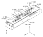
記録ヘッド2には、複数の記録素子基板H1100が千鳥状に配置されており、同一色による幅広の記録が可能に構成されている。本実施形態に係わる記録ヘッド2には、ノズル群の長さが1インチ+αの4つの記録素子基板H1100a、H1100b、H1100c、H1100dが千鳥状に配置されており、4インチ幅を記録可能に構成されている。ここでは、記録素子基板H1100の個数を4つとしたが、その数を増やすことで記録幅に合わせた記録ヘッドをスケーラブルに展開できる。
In the
各記録素子基板H1100の吐出口群の端部には、Y方向に沿って重複する領域(L)が設けられており、各記録素子基板H1100による記録に隙間が生じることを防止している。例えば、ノズル群H1106a及びノズル群H1106bの間には、重複領域H1109a及びH1109bが設けられている。 An area (L) overlapping in the Y direction is provided at the end of the ejection port group of each printing element substrate H1100, thereby preventing a gap from being generated in printing by each printing element substrate H1100. For example, overlapping regions H1109a and H1109b are provided between the nozzle group H1106a and the nozzle group H1106b.
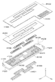
ここで、記録ヘッド2は、図3に示すように、記録素子ユニットH1001と、インク供給部材H1500とに大きく分けられる。なお、記録素子ユニットH1001には、上述した記録素子基板H1100が複数設けられている。
Here, as shown in FIG. 3, the
インク供給部材H1500は、例えば、樹脂成形により形成され、共通液室H1501と、Z方向基準H1502とを具備している。Z方向基準H1502は、記録素子ユニットH1001を位置決め固定するとともに、記録ヘッド2のZ方向への基準となる。
The ink supply member H1500 is formed by resin molding, for example, and includes a common liquid chamber H1501 and a Z-direction reference H1502. The Z-direction reference H1502 serves as a reference in the Z direction of the
ここで、記録素子ユニットH1001とインク供給部材H1500との結合の仕方について説明する。まず、インク供給部材H1500の開口と記録素子ユニットH1001を封止剤により封止し、共通液室H1501を2室に分離し密閉する。そして、例えば、ビスH1900等を用いて、インク供給部材H1500のZ方向基準H1502に記録素子ユニットH1001のZ方向基準(不図示)を位置決め固定する。なお、上述した封止剤は、耐インク性を有するとともに常温で硬化し、且つ異種材料間の線膨張差に耐えられる柔軟性を持つことが望ましい。 Here, a method of coupling the recording element unit H1001 and the ink supply member H1500 will be described. First, the opening of the ink supply member H1500 and the recording element unit H1001 are sealed with a sealant, and the common liquid chamber H1501 is separated into two chambers and sealed. Then, for example, the Z-direction reference (not shown) of the recording element unit H1001 is positioned and fixed to the Z-direction reference H1502 of the ink supply member H1500 using a screw H1900 or the like. Note that the above-described sealant desirably has ink resistance, is cured at room temperature, and has flexibility to withstand the difference in linear expansion between different materials.
次に、図4を用いて、記録素子ユニットH1001について更に説明する。記録素子ユニットH1001は、記録素子基板H1100と、第1のプレートH1200と、電気配線基板H1300と、第2のプレートH1400と、フィルター部材H1600とを具備して構成される。 Next, the recording element unit H1001 will be further described with reference to FIG. The recording element unit H1001 includes a recording element substrate H1100, a first plate H1200, an electric wiring substrate H1300, a second plate H1400, and a filter member H1600.
電気配線基板H1300は、インクを吐出するための電気信号を記録素子基板H1100に印加する。電気配線基板H1300には、記録素子基板H1100を組み込むための開口が形成されている。電気配線基板H1300の裏面には、第2のプレートH1400が接着固定される。 The electrical wiring substrate H1300 applies an electrical signal for ejecting ink to the recording element substrate H1100. An opening for incorporating the recording element substrate H1100 is formed in the electric wiring substrate H1300. The second plate H1400 is bonded and fixed to the back surface of the electrical wiring board H1300.
電気配線基板H1300には、記録素子基板H1100の電極(図5(a)に示すH1103)に対応する電極端子H1302と、記録装置本体から電気信号を受け取るための外部信号入力端子H1301とが設けられる。なお、記録素子ユニットH1001における外部信号入力端子H1301に対応するエリアは、例えば、図3に示すインク供給部材H1500の裏面に位置決め固定される。 The electrical wiring board H1300 is provided with an electrode terminal H1302 corresponding to an electrode (H1103 shown in FIG. 5A) of the recording element substrate H1100 and an external signal input terminal H1301 for receiving an electrical signal from the recording apparatus main body. . The area corresponding to the external signal input terminal H1301 in the recording element unit H1001 is positioned and fixed on the back surface of the ink supply member H1500 shown in FIG. 3, for example.
電気配線基板H1300は、記録素子基板H1100に電気的に接続されている。より具体的には、記録素子基板H1100の電極(図5(a)に示すH1103)と、電気配線基板H1300の電極端子H1302とがワイヤーボンディング技術により電気的に接続される。電気配線基板H1300の素材には、例えば、配線が二層構造のフレキシブル配線基板が使用され、その表層はポリイミドフィルムで覆われている。 The electrical wiring substrate H1300 is electrically connected to the recording element substrate H1100. More specifically, the electrode (H1103 shown in FIG. 5A) of the recording element substrate H1100 and the electrode terminal H1302 of the electric wiring substrate H1300 are electrically connected by a wire bonding technique. As a material of the electric wiring board H1300, for example, a flexible wiring board having a two-layer structure is used, and the surface layer is covered with a polyimide film.
第1のプレートH1200は、例えば、厚さ0.5〜10mmのアルミナで形成される。なお、第1のプレートH1200の素材は、アルミナに限られない。第1のプレートH1200は、例えば、記録素子基板H1100の材料の線膨張率と同等の線膨張率を有し、且つ記録素子基板H1100材料の熱伝導率と同等若しくはそれを越える熱伝導率を有する材料で作られても良い。より具体的には、第1のプレートH1200の素材は、例えば、シリコン(Si)、窒化アルミニウム(AlN)、ジルコニア、窒化珪素(Si3N4)、炭化珪素(SiC)、モリブデン(Mo)、タングステン(W)のうちいずれであっても良い。 The first plate H1200 is made of alumina having a thickness of 0.5 to 10 mm, for example. Note that the material of the first plate H1200 is not limited to alumina. For example, the first plate H1200 has a linear expansion coefficient equivalent to the linear expansion coefficient of the material of the recording element substrate H1100, and has a thermal conductivity equivalent to or exceeding the thermal conductivity of the material of the recording element substrate H1100. It may be made of materials. More specifically, the material of the first plate H1200 is, for example, silicon (Si), aluminum nitride (AlN), zirconia, silicon nitride (Si3N4), silicon carbide (SiC), molybdenum (Mo), tungsten (W ).
第1のプレートH1200には、記録素子基板H1100にインクを供給するためのインク供給口H1201が形成されている。記録素子基板H1100のインク供給口(図5(b)に示すH1101)が第1のプレートH1200のインク供給口H1201に対応する。また、記録素子基板H1100は、第1のプレートH1200に対して位置精度良く接着固定される。その接着剤は、例えば、粘度が低く、接触面に形成される接着層が薄く、且つ、硬化後、比較的高い硬度を有し、耐インク性のあるものが望ましい。例えば、エポキシ樹脂を主成分とした熱硬化接着剤、若しくは紫外線硬化併用型の熱硬化接着剤が挙げられる。なお、接着層の厚みは50μm以下が望ましい。 In the first plate H1200, an ink supply port H1201 for supplying ink to the recording element substrate H1100 is formed. The ink supply port (H1101 shown in FIG. 5B) of the recording element substrate H1100 corresponds to the ink supply port H1201 of the first plate H1200. The recording element substrate H1100 is bonded and fixed to the first plate H1200 with high positional accuracy. The adhesive is desirably, for example, a material having a low viscosity, a thin adhesive layer formed on the contact surface, a relatively high hardness after curing, and ink resistance. For example, the thermosetting adhesive which has an epoxy resin as a main component, or the ultraviolet curing combined use type thermosetting adhesive is mentioned. The thickness of the adhesive layer is desirably 50 μm or less.
第1のプレートH1200のインク供給口H1201には、インク中に混入された異物を取り除くため、フィルター部材H1600が接着固定される。また、第1のプレートH1200には、位置決め基準となるX方向基準H1204、Y方向基準H1205、Z方向基準H1206も設けられる。 A filter member H1600 is bonded and fixed to the ink supply port H1201 of the first plate H1200 in order to remove foreign matters mixed in the ink. The first plate H1200 is also provided with an X-direction reference H1204, a Y-direction reference H1205, and a Z-direction reference H1206, which are positioning references.
第2のプレートH1400は、例えば、厚さ0.5〜1mmのSUS板で形成される。なお、第2のプレートH1400の素材は、SUSに限られない。第2のプレートH1400は、例えば、耐インク性を有し、良好な平面性を有する材料で作られても良い。第2のプレートH1400は、第1のプレートH1200に接着固定された記録素子基板H1100を取り込む開口を有し、第1のプレートH1200に接着固定される。 The second plate H1400 is formed of a SUS plate having a thickness of 0.5 to 1 mm, for example. Note that the material of the second plate H1400 is not limited to SUS. The second plate H1400 may be made of a material having ink resistance and good flatness, for example. The second plate H1400 has an opening for taking in the recording element substrate H1100 bonded and fixed to the first plate H1200, and is bonded and fixed to the first plate H1200.
第2のプレートH1400の開口と、記録素子基板H1100の側面によって形成される溝との間には、封止剤が充填され、電気配線基板H1300の電気実装部が封止される。また、記録素子基板H1100の電極(図5(a)に示すH1103)も、封止剤で封止されており、電気接続部分がインクによる腐食や外的衝撃から保護される。 A sealant is filled between the opening of the second plate H1400 and the groove formed by the side surface of the recording element substrate H1100, and the electrical mounting portion of the electrical wiring substrate H1300 is sealed. Further, the electrodes (H1103 shown in FIG. 5A) of the recording element substrate H1100 are also sealed with a sealing agent, and the electrical connection portion is protected from ink corrosion and external impact.
次に、図5(a)及び図5(b)を用いて、記録素子基板H1100の構成の一例について説明する。図5(a)は、記録素子基板H1100の外観構成の一例を示し、図5(b)は、図5(a)に示すA−Aの断面の一例を示す。 Next, an example of the configuration of the recording element substrate H1100 will be described with reference to FIGS. 5 (a) and 5 (b). FIG. 5A shows an example of an external configuration of the recording element substrate H1100, and FIG. 5B shows an example of a cross section taken along line AA shown in FIG.
記録素子基板H1100には、例えば、厚さ0.5〜1mmのSi基板H1108で薄膜が形成されている。また、インク流路として長溝状の貫通口からなるインク供給口H1101が形成され、インク供給口H1101の両側に発熱抵抗素子H1102がそれぞれ1列ずつ千鳥状に配列されている。発熱抵抗素子H1102及びAl等の電気配線が成膜技術により形成されている。また、電気配線に電力を供給するため、電極H1103が設けられている。 On the recording element substrate H1100, for example, a thin film is formed of a Si substrate H1108 having a thickness of 0.5 to 1 mm. In addition, an ink supply port H1101 composed of a long groove-like through-hole is formed as an ink flow path, and the heating resistance elements H1102 are arranged in a staggered pattern on each side of the ink supply port H1101. The heating resistor element H1102 and electric wiring such as Al are formed by a film forming technique. An electrode H1103 is provided to supply power to the electrical wiring.
インク供給口H1101は、Si基板H1108の結晶方位を利用して、異方性エッチングを行う。ウエハー面に<100>、厚さ方向に<111>の結晶方位を持つ場合、アルカリ系(KOH、TMAH、ヒトラジン等)の異方性エッチングにより、約54.7度の角度でエッチングが進行する。この方法を用いて、所望の深さにエッチングされる。 The ink supply port H1101 performs anisotropic etching using the crystal orientation of the Si substrate H1108. When the wafer surface has a crystal orientation of <100> and a thickness direction of <111>, the etching proceeds at an angle of about 54.7 degrees by anisotropic etching (KOH, TMAH, humanradine, etc.) . Using this method, it is etched to the desired depth.
Si基板H1108上には、ノズルプレートH1110が設けられ、発熱抵抗素子H1102に対応して、インク流路H1104と、ノズルH1105と、発泡室H1107とがフォトリソ技術により形成されている。 A nozzle plate H1110 is provided on the Si substrate H1108, and an ink flow path H1104, a nozzle H1105, and a bubbling chamber H1107 are formed by photolithography technology corresponding to the heating resistance element H1102.
ノズルH1105は、発熱抵抗素子H1102に対向するように設けられており、インク供給口H1101から供給されたインクを発熱抵抗素子H1102により気泡を発生させてインクを吐出させる。 The nozzle H1105 is provided so as to face the heating resistance element H1102, and causes the ink supplied from the ink supply port H1101 to generate bubbles by the heating resistance element H1102 to discharge the ink.
ここで、図6は、記録素子基板H1100と温度センサとの位置関係の一例を示す図である。各記録素子基板H1100には、図6に示すように、当該基板の中央部に1つの温度センサH1120が設けられている。 Here, FIG. 6 is a diagram illustrating an example of a positional relationship between the recording element substrate H1100 and the temperature sensor. As shown in FIG. 6, each recording element substrate H1100 is provided with one temperature sensor H1120 at the center of the substrate.
図7は、記録ヘッド2における機能的な構成の一例を示す図である。
FIG. 7 is a diagram illustrating an example of a functional configuration of the
記録素子基板H1100(H1100a〜H1100d)には、記録素子(発熱抵抗素子)が複数配列されるとともに、その他の各種機能を提供する素子も設けられる。 In the recording element substrate H1100 (H1100a to H1100d), a plurality of recording elements (heating resistance elements) are arranged, and other elements providing various functions are also provided.
記録素子基板H1100に備わる温度センサH1120(不図示)の出力は、配線25(25a〜25d)によって引き出され、(アナログ)マルチプレクサ23に入力される。マルチプレクサ23は、いずれかの温度センサH1120の出力を選択する。当該選択された温度センサH1120の出力は、記録ヘッド2と外部とを電気的に接続するために設けられた出力用端子20を介して外部に取り出される。
An output of a temperature sensor H1120 (not shown) provided in the recording element substrate H1100 is drawn out by the wiring 25 (25a to 25d) and inputted to the (analog)
カウンタ22のデコード信号を利用することにより、各記録素子基板H1100の温度センサH1120の出力は、外部に取り出される。これにより、記録装置1においては、各記録素子基板H1100の温度に応じて、記録ヘッド2を温度制御することが可能となる。
By using the decode signal of the
図8は、図7に示す温度センサH1120とマルチプレクサ23との間の接続の一例を示す図である。この場合、温度センサH1120(H1120a〜H1120d)としては、ダイオードが用いられており、その順方向の電圧効果が温度特性を持つことを利用して温度検出が行なわれる。
FIG. 8 is a diagram illustrating an example of a connection between the temperature sensor H1120 and the
各温度センサH1120は、記録素子基板H1100にそれぞれ対応してその内部に設けられている。それら温度センサ(ダイオード)H1120のカソード電極をコモン電極33とし、それらアノード電極がマルチプレクサ23に接続される。
Each temperature sensor H1120 is provided corresponding to the recording element substrate H1100. The cathode electrodes of the temperature sensors (diodes) H1120 are used as the
マルチプレクサ23は、選択信号21を用いて、それらアノード電極を選択的に外部取り出し電極32を介して記録装置本体と接続する。なお、選択信号21は、記録装置本体側から入力される。記録装置本体は、マルチプレクサ23によって選択されたダイオードの順方向の電圧降下を読み取ることにより温度を検知する。
The
次に、図9を用いて、記録装置本体側(図1に示す制御部9)における機能的な構成の一例について説明する。ここでは、記録素子基板(例えば、温度センサ、ヒータ及び駆動回路、マルチプレクサ等)の異常の判定に係わる構成について例を挙げて説明する。
Next, an example of a functional configuration on the recording apparatus main body side (the
制御部9には、検出信号取得部41と、加熱制御部45と、異常判定部46と、タイマー部47とが設けられる。なお、これら機能的な構成は、例えば、CPUがROM(ReadOnly Memory)等に設けられるプログラムをRAM(Random Access Memory)をワーク領域にして実行することにより実現される。なお、その一部又は全てが専用のハードウェア構成として実現されても良い。
The
検出信号取得部41は、各記録素子基板H1100に設けられた温度センサH1120から検出信号(検出温度(測定温度))を取得する。検出信号取得部41には、第1の検出信号取得部42と、第2の検出信号取得部43と、第3の検出信号取得部44とが設けられる。
The detection
第1の検出信号取得部42は、記録素子基板H1100の異常を判定する異常判定処理に際して、複数の記録素子基板H1100に対して加熱が行なわれる前に各温度センサH1120から検出信号をそれぞれ取得する。
The first detection
第2の検出信号取得部43は、加熱中の記録素子基板H1100における温度センサH1120からの検出信号を取得する。なお、第3の検出信号取得部44は、実施形態1においては、特に機能せず、関係のない構成であるため、実施形態2で説明する。
The second detection
加熱制御部45は、記録素子基板H1100の加熱を制御する。より具体的には、発熱抵抗素子を発熱させることにより複数の記録素子基板H1100を(1つずつ)順番に加熱させる。なお、異常判定処理に際して、加熱制御部45は、インクが吐出されない程度に発熱抵抗素子を発熱させる(吐出前の準備)。
The
異常判定部46は、検出信号取得部41により取得された検出信号に基づいて、記録素子基板H1100の異常の有無を判定する。
The
タイマー部47は、所定の時間を計時する。以上が、制御部9上に実現される機能的な構成についての説明である。
The
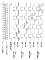
図10は、記録素子基板H1100異常判定を行なう際のタイミングチャートの一例を示す図である。なお、図10(図11、図12、図14、図16)に示す「選択された温度センサ」においては、温度センサを示す符号(H1120a〜H1120d)のアルファベット(a〜d)を用いて選択中の温度センサが示されている。 FIG. 10 is a diagram illustrating an example of a timing chart when the abnormality determination of the recording element substrate H1100 is performed. In the “selected temperature sensor” shown in FIG. 10 (FIGS. 11, 12, 14, and 16), selection is made using alphabets (a to d) of symbols (H1120a to H1120d) indicating the temperature sensors. The temperature sensor inside is shown.
記録素子基板H1100aにおいては、ヒータ加熱前、すなわちヒータに電圧のパルスを印加する前の温度がTt0(時刻t0)、ヒータ加熱後、すなわちヒータに電圧のパルスを印加開始した後の温度がTt1及びTt2となる。ヒータ加熱前後、すなわち電圧パルスを印加する前後の温度差(Tt1−Tt0、Tt2−Tt0)が予め定められた第1の閾値を越えていれば、記録素子基板H1100aが正常に動作していると判定できる。 In the recording element substrate H1100a, the temperature before the heater heating, that is, the temperature before applying the voltage pulse to the heater is Tt0 (time t0), and the temperature after the heater heating, that is, after the voltage pulse is started to be applied to the heater is Tt1. Tt2. If the temperature difference (Tt1-Tt0, Tt2-Tt0) before and after heating the heater, that is, before and after applying the voltage pulse, exceeds a predetermined first threshold, the recording element substrate H1100a is operating normally. Can be judged.
異常判定処理は、各記録素子基板H1100において実施される。具体的には、異常判定処理は、時刻t4〜t7においては記録素子基板H1100bで実施され、時刻t8〜t11においては記録素子基板H1100cで実施され、時刻t12〜t15においては記録素子基板H1100dで実施される。 The abnormality determination process is performed on each recording element substrate H1100. Specifically, the abnormality determination process is performed on the recording element substrate H1100b from time t4 to t7, is performed on the recording element substrate H1100c from time t8 to t11, and is performed on the recording element substrate H1100d from time t12 to t15. Is done.
図11に、各記録素子基板の温度センサを順次選択するための選択回路(マルチプレクサ23)や、電気配線基板H1300に設けられた配線や、記録素子基板H1100の電極H1103と電気配線基板H1300の電極端子H1302とのボンディング等に不具合が生じて温度センサの出力を正常に検出できない場合を示す。 FIG. 11 shows a selection circuit (multiplexer 23) for sequentially selecting the temperature sensor of each recording element substrate, wiring provided on the electrical wiring substrate H1300, electrodes H1103 of the recording element substrate H1100, and electrodes of the electrical wiring substrate H1300. A case where a defect occurs in bonding with the terminal H1302 and the output of the temperature sensor cannot be normally detected is shown.
図11には、いずれの温度検出タイミングにおいても、記録素子基板H1100aの温度センサH1120aが何らかの不具合で常に選択されるようになっている場合を示している。このような状況では、記録素子基板H1100bにおける温度センサH1120bに何らかの不具合が生じていたとしても、異常はないと判定されてしまう。つまり、記録素子基板の状態を誤判定してしまう。 FIG. 11 shows a case where the temperature sensor H1120a of the recording element substrate H1100a is always selected for some reason at any temperature detection timing. In such a situation, it is determined that there is no abnormality even if some trouble occurs in the temperature sensor H1120b in the recording element substrate H1100b. That is, the state of the recording element substrate is erroneously determined.
図10を用いて説明した通り、記録素子基板H1100bにおける温度センサH1120bは、本来、時刻t4から検出信号(検出温度)を出力する予定であるが、図11においては、時刻t4において記録素子基板H1100aの検出信号が出力されている。 As described with reference to FIG. 10, the temperature sensor H1120b in the recording element substrate H1100b originally intends to output a detection signal (detection temperature) from time t4, but in FIG. 11, the recording element substrate H1100a at time t4. The detection signal is output.
また、時刻t4以降は、各記録素子基板H1100の異常判定を順次行なうはずであるが、記録素子基板H1100aの検出信号が出力され続けている。そのため、いずれの記録素子基板H1100においても、検出信号の出力差が第1の閾値を越えていると判定され、見かけ上、正常であると誤った判定をされてしまう。 Further, after time t4, the abnormality determination of each recording element substrate H1100 should be sequentially performed, but the detection signal of the recording element substrate H1100a continues to be output. Therefore, in any recording element substrate H1100, it is determined that the output difference of the detection signal exceeds the first threshold value, and it is erroneously determined that it is apparently normal.
ここで、図12を用いて、このような事態に対処する本実施形態における手法について説明する。 Here, a method in the present embodiment for dealing with such a situation will be described with reference to FIG.
本実施形態では、図12に示すように、異常判定における各タイミングにおいて、複数の記録素子基板H1100全てを加熱せず、いずれか1つのみを選択的に加熱する。すなわち、異常判定の対象となる記録素子基板の記録素子のみを駆動させ、それ以外の記録素子基板の記録素子は同時に駆動させない。 In the present embodiment, as shown in FIG. 12, not all of the plurality of recording element substrates H1100 are heated at each timing in abnormality determination, but only one of them is selectively heated. That is, only the recording element of the recording element substrate that is the target of abnormality determination is driven, and the recording elements of the other recording element substrates are not driven simultaneously.
次に、図13を用いて、図1に示す記録装置1における処理の流れの一例について説明する。ここでは、温度センサH1120やマルチプレクサ23、ヒータ等における異常を判定する際の処理の流れの一例について説明する。
Next, an example of the flow of processing in the recording apparatus 1 shown in FIG. 1 will be described with reference to FIG. Here, an example of the flow of processing when determining an abnormality in the temperature sensor H1120, the
この処理が開始すると、記録装置1は、まず、第1の検出信号取得部42において、異常判定の対象となる記録素子基板全ての温度センサの出力(Tini_n、Tini_n+1、・・・)を取得する(S101)。このタイミングでは、いずれの記録素子基板においても、ヒータの加熱制御が行なわれていないので、正常な状態であれば、ほぼ同じ温度が取得される。
When this process starts, the recording apparatus 1 first acquires the outputs (Tini_n, Tini_n + 1,...) Of the temperature sensors of all the recording element substrates to be subjected to abnormality determination in the first detection
続いて、記録装置1は、加熱制御部45において、記録素子基板N(Nの初期値は1)の加熱をオンするとともに(S102)、タイマー部47において、タイマーの計時を開始する(S103)。記録装置1は、第2の検出信号取得部43において、記録素子基板Nの検出温度Ton_nを取得し(S104)、異常判定部46において、加熱前の温度との温度差Ton_n−Tini_nが第1の閾値Tjを越えているか否かを判定する。
Subsequently, in the recording apparatus 1, the
判定の結果、第1の閾値Tjを越えていない、すなわち、所定の温度差以下であれば(S105でNO)、記録装置1は、加熱時間が加熱制限となる時間(加熱制限時間)P秒を越えるまで(S106でNO)、S104〜S106の処理を繰り返し実施する。加熱時間がP秒を越えれば(S106でYES)、加熱オンしているにも関わらず温度が上がっていないため異常であると判定し、記録装置1は、エラー処理を行なった後(S107)、この処理を終了する。 As a result of the determination, if the first threshold value Tj is not exceeded, that is, if the temperature difference is equal to or smaller than the predetermined temperature difference (NO in S105), the recording apparatus 1 is time for which the heating time becomes the heating limit (heating limit time) P seconds. Until it exceeds (NO in S106), the processes of S104 to S106 are repeated. If the heating time exceeds P seconds (YES in S106), it is determined that there is an abnormality because the temperature has not risen despite the heating being turned on, and the recording apparatus 1 performs error processing (S107). This process is terminated.
また、S105の判定の結果、第1の閾値Tjを越えていれば(S105でYES)、記録装置1は、記録素子基板Nが正常であると判定し、加熱オフ及びタイマーリセットを実施する(S108)。 If the result of determination in S105 is that the first threshold value Tj has been exceeded (YES in S105), the recording apparatus 1 determines that the recording element substrate N is normal, and performs heating off and timer reset ( S108).
ここで、記録装置1は、全ての記録素子基板の異常判定が終了したか否かを判定し、終了していれば(S109でYES)、この処理を終了する。終了していなければ(S109でNO)、記録装置1は、次の記録素子基板(N=N+1)を選択する(S110)。なお、ここでは、Nを「1」インクリメントし、支持プレートに配置された順番で異常判定処理を行なう場合について説明したが、予め定められたテーブル等で記録素子基板の個数、順番を指定することも可能である。 Here, the recording apparatus 1 determines whether or not the abnormality determination for all the recording element substrates has been completed. If the determination has been completed (YES in S109), the processing ends. If not completed (NO in S109), the printing apparatus 1 selects the next printing element substrate (N = N + 1) (S110). Here, the case where N is incremented by “1” and the abnormality determination process is performed in the order in which they are arranged on the support plate has been described. However, the number and order of the recording element substrates are designated by a predetermined table or the like. Is also possible.
以上説明したように本実施形態によれば、判定の対象となる記録素子基板の記録素子のみを駆動させ、それ以外の記録素子基板の記録素子は同時に駆動させない。 As described above, according to the present embodiment, only the recording elements of the recording element substrate to be determined are driven, and the recording elements of the other recording element substrates are not driven simultaneously.
これにより、例えば、選択回路(マルチプレクサ)や、電気配線基板H1300に設けられた配線や、記録素子基板H1100の電極H1103と電気配線基板H1300の電極端子H1302とのボンディング等に不具合がある場合であっても、異常はないと誤判定してしまうことを防止できる。つまり、記録素子基板の異常判定結果の信頼性を向上させることができる。 Thereby, for example, there is a problem in the selection circuit (multiplexer), the wiring provided on the electrical wiring substrate H1300, the bonding between the electrode H1103 of the recording element substrate H1100 and the electrode terminal H1302 of the electrical wiring substrate H1300, or the like. However, it is possible to prevent erroneous determination that there is no abnormality. That is, the reliability of the abnormality determination result of the recording element substrate can be improved.
(実施形態2)
次に、実施形態2について説明する。実施形態2においては、記録ヘッド2の熱伝導特性が実施形態1と異なる場合について説明する。なお、記録ヘッドの熱伝導特性は、例えば、各記録素子基板の支持プレートの材質、形状によって変わってくる。
(Embodiment 2)
Next,
図14は、記録素子基板H1100異常判定を行なう際のタイミングチャートの一例を示す図である。なお、ここでは、記録素子基板H1100a及びH1100bのみ例に挙げて説明し、記録素子基板H1100c及びH1100dについての説明は省略する。 FIG. 14 is a diagram illustrating an example of a timing chart when the abnormality determination of the recording element substrate H1100 is performed. Here, only the recording element substrates H1100a and H1100b will be described as an example, and description of the recording element substrates H1100c and H1100d will be omitted.
図14を参照すると、実施形態1を説明した記録ヘッドに比べて、ヒータ加熱の開始時刻、終了時刻が同じであったとしても、加熱開始前の温度に戻るまでに長い時間を要することが分かる。 Referring to FIG. 14, it can be seen that it takes a longer time to return to the temperature before the start of heating, even if the heater heating start time and end time are the same as in the recording head described in the first embodiment. .
記録素子基板H1100bにおいては、記録素子基板H1100aが加熱された影響により、その検出温度が高くなっている。記録素子基板H1100bの異常判定処理においては、ヒータ加熱前、すなわちヒータに電圧のパルスを印加する前の温度(時刻t4)も、既に高い状態となる。そのため、ヒータ加熱後、すなわちヒータに電圧のパルスの印加を開始した後との温度差(Tt5−Tt4、Tt6−Tt4)は、記録素子基板H1100aの異常処理時の温度差(Tt1−Tt0、Tt2−Tt0)よりも小さくなる。従って、第1の閾値を越えていないと判定される可能性があり、正常な状態にも関わらず、見掛け上は異常と判定されてしまう不具合が生じる場合がある。 In the recording element substrate H1100b, the detection temperature is high due to the effect of the recording element substrate H1100a being heated. In the abnormality determination process for the recording element substrate H1100b, the temperature (time t4) before heating the heater, that is, before applying a voltage pulse to the heater, is already high. Therefore, the temperature difference (Tt5-Tt4, Tt6-Tt4) after the heater is heated, that is, after the voltage pulse is started to be applied to the heater, is the temperature difference (Tt1-Tt0, Tt2) during the abnormal processing of the recording element substrate H1100a. -Tt0). Therefore, there is a possibility that it is determined that the first threshold value is not exceeded, and there may be a problem that, despite the normal state, it is apparently determined to be abnormal.
ここで、図15を用いて、実施形態2に係わる記録装置1における処理の流れの一例について説明する。ここでは、温度センサH1120やマルチプレクサ23、ヒータ等における異常を判定する際の処理の流れの一例について説明する。なお、S201〜S210の処理は、実施形態1を説明した図13におけるS101〜S110の処理と同様であるため、ここでは、S211以降の処理について説明する。
Here, an example of a processing flow in the recording apparatus 1 according to the second embodiment will be described with reference to FIG. Here, an example of the flow of processing when determining an abnormality in the temperature sensor H1120, the
記録装置1は、S210の処理で次の記録素子基板を選択すると、タイマー部47において、タイマー計時を開始する(S211)。そして、第3の検出信号取得部44において、記録素子基板Nの温度センサから当該基板Nの現在の温度Toff_nを取得する(S212)。
When the recording device 1 selects the next recording element substrate in the process of S210, the
ここで、記録装置1は、加熱制御部45において、S201で取得済みの加熱制御前の検出温度Tini_nとの温度差Toff_n−Tini_nが第2の閾値Tkを越えているか否かを判定する。第2の閾値Tkを越えていなければ(S213でNO)、ほぼ熱伝導の影響がないと判定できるので、タイマーをリセットした後(S215)、S202の処理に進み。すなわち、記録素子基板Nを加熱し、上記同様の処理を実施する。
Here, the recording apparatus 1 determines in the
一方、S213の判定の結果、温度差Toff_n−Tini_nが第2の閾値Tkを越えていれば(S213でYES)、記録装置1は、時間Q秒を越えるまで(S214でNO)、S212〜S213の処理を繰り返し実施する。時間Q秒を越えれば(S214でYES)、記録装置1は、エラー処理を行なった後(S207)、この処理を終了する。 On the other hand, as a result of the determination in S213, if the temperature difference Toff_n-Tini_n exceeds the second threshold value Tk (YES in S213), the recording apparatus 1 continues to S212 to S213 until it exceeds the time Q seconds (NO in S214). Repeat the process. If the time exceeds Q seconds (YES in S214), the recording apparatus 1 performs error processing (S207) and ends this processing.
ここで、図16を用いて、図15で説明した処理のタイミングチャートについて説明する。 Here, a timing chart of the process described with reference to FIG. 15 will be described with reference to FIG.
記録素子基板H1100bは、記録素子基板H1100aを加熱制御した際の熱伝導影響を受けるが、記録素子基板H1100bに電圧のパルスを印加して加熱を開始する前に、予め測定された値との温度差が第2の閾値以下となるように放熱するための十分な時間を設けている。そのため、異常判定処理時には、当該熱伝導の影響を排除できる。 The recording element substrate H1100b is affected by heat conduction when the recording element substrate H1100a is controlled to be heated. However, before the heating is started by applying a voltage pulse to the recording element substrate H1100b, the temperature of the recording element substrate H1100b is measured. Sufficient time is provided for heat dissipation so that the difference is equal to or less than the second threshold. Therefore, the influence of the heat conduction can be eliminated during the abnormality determination process.
また、実施形態2に係わる記録ヘッド2における熱伝導特性を考慮すれば、ある記録素子基板を過熱した後、Y方向(ノズル配列方向)に沿って隣接しない記録素子基板を次に加熱する記録素子基板として選択しても良い。図6を参照して具体的に説明すると、例えば、H1106a、H1106c、H1106b、H1106dの順番で加熱する基板を選択しても良い。この場合、記録素子基板同士の距離が離散的になるように基板の加熱が行なわれるため、異常判定処理に要する時間を短縮することができる。
In consideration of the heat conduction characteristics of the
以上説明したように実施形態2によれば、第1の記録素子基板に対して異常の有無の判定を行なった後に、第2の記録素子基板に対して異常の有無の判定を行なうときにも、記録素子基板の状態判定を正確に行なえる。すなわち、実施形態2によれば、どのような熱伝導特性を有する記録ヘッドであっても、実施形態1同様の効果が得られる。 As described above, according to the second embodiment, after determining whether there is an abnormality in the first recording element substrate, it is also possible to determine whether there is an abnormality in the second recording element substrate. Thus, it is possible to accurately determine the state of the recording element substrate. That is, according to the second embodiment, the same effect as that of the first embodiment can be obtained regardless of the thermal conductivity of the recording head.
(実施形態3)
次に、実施形態3について説明する。実施形態2のように熱伝導の影響を受ける記録ヘッドの構成では、できるだけ熱伝導の影響を受けないように電圧のパルスを印加して加熱を開始する加熱制御の開始前に十分なウェイト時間を確保していた。そのため、実施形態1に係わる記録ヘッドと比べると異常判定処理に時間を要することになる。そこで、実施形態3においては、このウェイト時間を短縮する方法について説明する。
(Embodiment 3)
Next,
図17(a)は、実施形態3に係わる記録ヘッド2の部分的断面を模式的に示した図である。
FIG. 17A schematically illustrates a partial cross section of the
記録素子基板H1100は、記録素子の配列方向に沿って4個配置されている。また、記録素子基板各々に対応してフィルター部材H1600が設けられている。記録素子基板H1100とフィルター部材H1600との間には、インク流路が形成される。各記録素子基板H1100にインクを供給する共通液室H1501は、複数に分離されており、各液室の両端部には、インク流出口が設けられる。 Four recording element substrates H1100 are arranged along the arrangement direction of the recording elements. A filter member H1600 is provided for each recording element substrate. An ink flow path is formed between the recording element substrate H1100 and the filter member H1600. The common liquid chamber H1501 for supplying ink to each recording element substrate H1100 is divided into a plurality of portions, and ink outlets are provided at both ends of each liquid chamber.
ここで、図17(b)に示すように、各液室を連結するインク流路にインクを循環すると、各記録素子基板H1100で発生した熱がインクに伝熱する。そのため、インクが循環する上流側の記録素子基板の熱は、下流側の記録素子基板にインクを介して伝わりやすい状態にある。つまり、1循環路に属する記録素子を均一な記録デューティーで駆動させた場合、入口側(インクの上流側)よりも出口側(インクの下流側)の方に向かって温度勾配が生じることになる。 Here, as shown in FIG. 17B, when the ink is circulated through the ink flow path connecting the liquid chambers, the heat generated in each recording element substrate H1100 is transferred to the ink. Therefore, the heat of the upstream recording element substrate through which the ink circulates is easily transmitted to the downstream recording element substrate via the ink. That is, when the printing elements belonging to one circulation path are driven at a uniform printing duty, a temperature gradient is generated from the inlet side (ink upstream side) toward the outlet side (ink downstream side). .
このように熱伝導に方向性を持つ記録ヘッド2においては、上述した異常判定処理をインク循環方向の下流側の記録素子基板から順次実施する。これにより、インクを介した熱伝導の影響を低減できる。
As described above, in the
また、実施形態3に係わる記録ヘッド2の記録素子基板H1100は、図17(c)に示すように、複数の温度センサ(p,q,r)も備えられており、それらも基板間の温度センサ同様に選択回路(不図示)により制御される。すなわち、記録装置本体側(制御部9)においては、複数の温度センサ(p,q,r)からの出力を別々に取得できる。一般に、記録素子基板は、支持プレートよりも熱伝導特性が良いシリコン基板等により形成されているので、同一基板内で異常判定処理が連続しないようにすることも処理時間の短縮につながる。
The recording element substrate H1100 of the
また、記録素子基板H1100は、当該基板の外周をアルミ配線で這い回し、温度変化に対し抵抗値が変化する別構成の温度センサを搭載している。このように複数種の温度センサを搭載する構成において、異常判定処理を行なう場合、温度センサ、ヒータ及び駆動回路などの異常箇所を特定することもできる。 Further, the recording element substrate H1100 is mounted with a temperature sensor having a different configuration in which the outer periphery of the substrate is wound around with an aluminum wiring and the resistance value changes in response to a temperature change. Thus, when performing abnormality determination processing in a configuration in which a plurality of types of temperature sensors are mounted, it is possible to identify abnormal portions such as a temperature sensor, a heater, and a drive circuit.
以上説明したように実施形態3によれば、インクの循環に起因した熱伝導特性を考慮して記録素子基板の加熱制御を行なうため、実施形態2のような熱伝導特性を持つ記録ヘッドであっても、異常判定処理を迅速に行なえる。 As described above, according to the third embodiment, since the heating of the recording element substrate is controlled in consideration of the heat conduction characteristics due to the circulation of the ink, the recording head has the heat conduction characteristics as in the second embodiment. However, the abnormality determination process can be performed quickly.
以上が本発明の代表的な実施形態の例であるが、本発明は、上記及び図面に示す実施形態に限定することなく、その要旨を変更しない範囲内で適宜変形して実施できるものである。 The above is an example of a typical embodiment of the present invention, but the present invention is not limited to the embodiment described above and shown in the drawings, and can be appropriately modified and implemented within the scope not changing the gist thereof. .
なお、上述した実施形態1〜3においては、異常判定処理の実施タイミングについては特に説明していないが、例えば、記録装置1の電源オン時等に実施すれば良い。また、記録処理後(又は電源オフ)の経過時間に応じて実施するか否かを決めても良い。なお、記録処理後(又は電源オフ)の経過時間に応じて実施するか否かを決めるのは、記録処理の実行後は、記録デューティーにも依存するが、記録ヘッドに熱分布が生じている可能性が高く、熱分布が大きければ、異常判定時に誤判定の要因となるためである。 In the first to third embodiments described above, the execution timing of the abnormality determination process is not particularly described, but may be performed, for example, when the recording apparatus 1 is turned on. Further, it may be determined whether or not the recording is performed according to the elapsed time after the recording process (or power off). Note that whether or not to determine whether or not to carry out according to the elapsed time after the recording process (or power off) depends on the recording duty after the execution of the recording process, but heat distribution is generated in the recording head. This is because if the possibility is high and the heat distribution is large, it becomes a factor of erroneous determination at the time of abnormality determination.
また、上述した実施形態1〜3においては、複数の記録素子基板が千鳥状に複数配されるフルラインタイプの記録ヘッドを例に挙げて説明したが、これに限られない。すなわち、1又は複数の温度センサを有する複数の記録素子基板が配置される記録ヘッドであれば何でも良い。 In the first to third embodiments described above, a full-line type recording head in which a plurality of recording element substrates are arranged in a staggered manner has been described as an example. However, the present invention is not limited to this. That is, any recording head on which a plurality of recording element substrates having one or a plurality of temperature sensors are arranged may be used.
また、上述した実施形態1〜3においては、ヒータ加熱前後、すなわち電圧パルスを印加する前後の温度差が予め定められた第1の閾値を越えているか否かに応じて異常の判定を行なう場合について説明したが(図13のS105参照)、これに限られない。例えば、予め決められた所定の温度(第1の温度)を越えているか否かに基づいて異常の判定を行なうようにしても良い。 In the first to third embodiments described above, the abnormality is determined depending on whether the temperature difference before and after heating the heater, that is, before and after applying the voltage pulse, exceeds a predetermined first threshold value. Has been described (see S105 in FIG. 13), but is not limited thereto. For example, the abnormality determination may be performed based on whether or not a predetermined temperature (first temperature) is exceeded.
また更に、実施形態2で説明した第2の閾値についても同様に、温度差ではなく、所定の温度(第2の温度)を越えているか否かに基づいてほぼ熱伝導の影響がないと判定するようにしても良い(図15のS213)。すなわち、第2の温度以下であれば、次の記録素子基板に対する処理を実施するようにしても良い。 Furthermore, similarly, the second threshold value described in the second embodiment is determined to have almost no influence of heat conduction based on whether or not a predetermined temperature (second temperature) is exceeded rather than a temperature difference. You may make it do (S213 of FIG. 15). That is, if the temperature is equal to or lower than the second temperature, the processing for the next recording element substrate may be performed.
Claims (7)
前記複数の記録素子基板のうち、前記選択手段によって選択された前記温度センサが設けられた記録素子基板における前記記録素子のみを駆動したときに当該温度センサによって測定される温度に基づいて、当該記録素子基板の異常の有無を判定する判定動作を行う判定手段を備え、
前記判定手段は、ある記録素子基板に対する前記判定動作を行った後に、当該判定動作を行った記録素子基板に隣接しない記録素子基板に対する前記判定動作を次に行う
ことを特徴とする記録装置。 A plurality of recording elements that ejects ink using thermal energy, provided in correspondence with each of the plurality of recording element substrates arranged along the arrangement direction of the recording elements, and the plurality of recording element substrates; A recording apparatus comprising: a temperature sensor that measures the temperature of the recording element substrate; and a selection unit that selects any one of the plurality of temperature sensors,
Based on the temperature measured by the temperature sensor when only the recording element in the recording element substrate provided with the temperature sensor selected by the selection unit is driven among the plurality of recording element substrates. A determination means for performing a determination operation for determining whether there is an abnormality in the element substrate,
The determination unit performs the determination operation on a recording element substrate not adjacent to the recording element substrate on which the determination operation is performed after performing the determination operation on a certain recording element substrate.
前記複数の記録素子基板のうち、前記選択手段によって選択された前記温度センサが設けられた記録素子基板における前記記録素子のみを駆動したときに当該温度センサによって測定される温度に基づいて、当該記録素子基板の異常の有無を判定する判定動作を行う判定手段を備え、
前記判定手段は、前記インク流路の下流側に位置する記録素子基板から順番に前記判定動作を行う
ことを特徴とする記録装置。 A plurality of recording elements that ejects ink using thermal energy, a plurality of recording element substrates arranged along an arrangement direction of the recording elements, and a common for supplying ink to the plurality of recording element substrates An ink flow path, a temperature sensor that is provided corresponding to each of the plurality of recording element substrates, measures a temperature of the recording element substrate, and a selection unit that selects any one of the plurality of temperature sensors. A recording device comprising:
Based on the temperature measured by the temperature sensor when only the recording element in the recording element substrate provided with the temperature sensor selected by the selection unit is driven among the plurality of recording element substrates. A determination means for performing a determination operation for determining whether there is an abnormality in the element substrate,
The determination unit performs the determination operation in order from a recording element substrate located on the downstream side of the ink flow path.
ことを特徴とする請求項1又は2に記載の記録装置。 The determination unit is configured such that a temperature difference between a first temperature measured by the temperature sensor before driving the recording element and a second temperature measured by the temperature sensor after driving the recording element is a threshold value. 3. The recording apparatus according to claim 1, wherein the recording apparatus is determined to be normal when the temperature difference is exceeded, and is determined to be abnormal when the temperature difference is equal to or less than the threshold value.
前記加熱制御部は、前記判定手段が前記判定動作を行う際には、インクが吐出されない程度に前記記録素子を駆動する
ことを特徴とする請求項3に記載の記録装置。 A heating control unit for driving the recording element;
The recording apparatus according to claim 3, wherein the heating control unit drives the recording element to such an extent that ink is not ejected when the determination unit performs the determination operation .
ことを特徴とする請求項4に記載の記録装置。 The recording apparatus according to claim 4 , wherein the heating control unit drives the recording element after a temperature measured by the temperature sensor becomes equal to or lower than a predetermined temperature.
複数の前記温度センサのいずれか1つを選択する選択工程と、
前記複数の記録素子基板のうち、前記選択工程で選択された前記温度センサが設けられた記録素子基板における前記記録素子のみを駆動したときに当該温度センサによって測定される温度に基づいて、当該記録素子基板の異常の有無を判定する判定動作を行う判定工程と、を含み、
前記判定工程では、ある記録素子基板に対する前記判定動作を行った後に、当該判定動作を行った記録素子基板に隣接しない記録素子基板に対する前記判定動作を次に行う
ことを特徴とする記録装置の判定方法。 A plurality of recording elements that ejects ink using thermal energy, provided in correspondence with each of the plurality of recording element substrates arranged along the arrangement direction of the recording elements, and the plurality of recording element substrates; A temperature sensor for measuring the temperature of the recording element substrate, and a determination method for a recording apparatus comprising:
A selection step of selecting any one of the plurality of temperature sensors;
Based on the temperature measured by the temperature sensor when only the recording element in the recording element substrate provided with the temperature sensor selected in the selection step is driven among the plurality of recording element substrates. A determination step of performing a determination operation for determining whether there is an abnormality in the element substrate,
In the determination step, after performing the determination operation on a certain recording element substrate, the determination operation on a recording element substrate that is not adjacent to the recording element substrate on which the determination operation is performed is performed next. Method.
複数の前記温度センサのいずれか1つを選択する選択工程と、
前記複数の記録素子基板のうち、前記選択工程で選択された前記温度センサが設けられた記録素子基板における前記記録素子のみを駆動したときに当該温度センサによって測定される温度に基づいて、当該記録素子基板の異常の有無を判定する判定動作を行う判定工程と、を含み、
前記判定工程では、前記インク流路の下流側に位置する記録素子基板から順番に前記判定動作を行う
ことを特徴とする記録装置の判定方法。 A plurality of recording elements that ejects ink using thermal energy, a plurality of recording element substrates arranged along an arrangement direction of the recording elements, and a common for supplying ink to the plurality of recording element substrates And a temperature sensor that is provided corresponding to each of the plurality of recording element substrates and that measures the temperature of the recording element substrate.
A selection step of selecting any one of the plurality of temperature sensors;
Based on the temperature measured by the temperature sensor when only the recording element in the recording element substrate provided with the temperature sensor selected in the selection step is driven among the plurality of recording element substrates. A determination step of performing a determination operation for determining whether there is an abnormality in the element substrate,
In the determination step, the determination operation is performed in order from the recording element substrate positioned on the downstream side of the ink flow path.
Priority Applications (2)
| Application Number | Priority Date | Filing Date | Title |
|---|---|---|---|
| JP2011272752A JP5379842B2 (en) | 2011-01-31 | 2011-12-13 | Recording apparatus and determination method thereof |
| US13/334,758 US8740333B2 (en) | 2011-01-31 | 2011-12-22 | Printing apparatus and determination method thereof |
Applications Claiming Priority (3)
| Application Number | Priority Date | Filing Date | Title |
|---|---|---|---|
| JP2011019147 | 2011-01-31 | ||
| JP2011019147 | 2011-01-31 | ||
| JP2011272752A JP5379842B2 (en) | 2011-01-31 | 2011-12-13 | Recording apparatus and determination method thereof |
Publications (3)
| Publication Number | Publication Date |
|---|---|
| JP2012176603A JP2012176603A (en) | 2012-09-13 |
| JP2012176603A5 JP2012176603A5 (en) | 2013-04-04 |
| JP5379842B2 true JP5379842B2 (en) | 2013-12-25 |
Family
ID=46577014
Family Applications (1)
| Application Number | Title | Priority Date | Filing Date |
|---|---|---|---|
| JP2011272752A Expired - Fee Related JP5379842B2 (en) | 2011-01-31 | 2011-12-13 | Recording apparatus and determination method thereof |
Country Status (2)
| Country | Link |
|---|---|
| US (1) | US8740333B2 (en) |
| JP (1) | JP5379842B2 (en) |
Families Citing this family (17)
| Publication number | Priority date | Publication date | Assignee | Title |
|---|---|---|---|---|
| US8798409B2 (en) * | 2010-10-07 | 2014-08-05 | Alcatel Lucent | Optical transmitter with flip-chip mounted laser or integrated arrayed waveguide grating wavelenth division multiplexer |
| JP5939919B2 (en) | 2011-10-12 | 2016-06-22 | キヤノン株式会社 | Inkjet recording apparatus and inkjet recording method |
| JP5584733B2 (en) | 2012-06-08 | 2014-09-03 | キヤノン株式会社 | Recording apparatus and printed matter discharge method |
| JP6043101B2 (en) | 2012-06-18 | 2016-12-14 | キヤノン株式会社 | Recording apparatus and recording method therefor |
| EP2864123B1 (en) * | 2012-09-25 | 2019-08-07 | Hewlett-Packard Development Company, L.P. | Print head die with thermal control |
| US9050840B2 (en) | 2013-09-05 | 2015-06-09 | Canon Kabushiki Kaisha | Printing apparatus and method for correcting printing position shift |
| JP6363851B2 (en) * | 2014-02-28 | 2018-07-25 | キヤノン株式会社 | Recording apparatus and recording head |
| US10166763B2 (en) | 2014-06-18 | 2019-01-01 | Canon Kabushiki Kaisha | Printing apparatus, printing method and storage medium |
| JP6333200B2 (en) | 2015-03-05 | 2018-05-30 | キヤノン株式会社 | Inkjet recording apparatus, inkjet recording method, and recording head |
| JP6965026B2 (en) * | 2017-05-29 | 2021-11-10 | キヤノン株式会社 | Recording device and recording method |
| US10406808B2 (en) | 2017-06-28 | 2019-09-10 | Canon Kabushiki Kaisha | Printing apparatus and printhead substrate |
| JP7119719B2 (en) * | 2018-07-30 | 2022-08-17 | コニカミノルタ株式会社 | Heaters and inkjet printers |
| JP7344704B2 (en) * | 2018-08-07 | 2023-09-14 | キヤノン株式会社 | Recording device and method for determining its nozzle discharge state |
| JP7266424B2 (en) * | 2019-02-28 | 2023-04-28 | キヤノン株式会社 | DEVICE SUBSTRATE, PRINT HEAD, AND PRINTING DEVICE |
| JP7451257B2 (en) | 2020-03-26 | 2024-03-18 | キヤノン株式会社 | Inkjet recording device and inkjet recording method |
| JP7549472B2 (en) | 2020-06-24 | 2024-09-11 | キヤノン株式会社 | Recording device, control method, storage medium, and program |
| JP2023090140A (en) | 2021-12-17 | 2023-06-29 | キヤノン株式会社 | Inkjet recording device, control method and program |
Family Cites Families (16)
| Publication number | Priority date | Publication date | Assignee | Title |
|---|---|---|---|---|
| JPH03104654A (en) * | 1989-09-19 | 1991-05-01 | Canon Inc | Ink jet recorder and temperature controller used therefor |
| JPH03176155A (en) | 1989-12-06 | 1991-07-31 | Canon Inc | Ink jet recorder |
| US5315316A (en) * | 1991-10-29 | 1994-05-24 | Hewlett-Packard Company | Method and apparatus for summing temperature changes to detect ink flow |
| JPH0768790A (en) * | 1993-09-02 | 1995-03-14 | Canon Inc | Ink jet recorder |
| JP3244937B2 (en) * | 1994-04-22 | 2002-01-07 | キヤノン株式会社 | Ink jet recording apparatus and recording method |
| JP3368147B2 (en) * | 1996-07-04 | 2003-01-20 | キヤノン株式会社 | Printhead and printing equipment |
| JPH11138788A (en) * | 1997-11-14 | 1999-05-25 | Canon Inc | Inspection method for recording head and recorder |
| US6652053B2 (en) * | 2000-02-18 | 2003-11-25 | Canon Kabushiki Kaisha | Substrate for ink-jet printing head, ink-jet printing head, ink-jet cartridge, ink-jet printing apparatus, and method for detecting ink in ink-jet printing head |
| US6398333B1 (en) * | 2000-08-09 | 2002-06-04 | Lexmark International, Inc | Print head temperature adjustment based on media type |
| US7295224B2 (en) * | 2001-08-22 | 2007-11-13 | Polaroid Corporation | Thermal response correction system |
| TWI275495B (en) * | 2004-09-21 | 2007-03-11 | Sony Corp | Printer and printing method |
| US7782350B2 (en) | 2006-12-13 | 2010-08-24 | Canon Kabushiki Kaisha | Printing apparatus, printing system, printhead temperature retaining control method |
| JP5072573B2 (en) | 2007-01-09 | 2012-11-14 | キヤノン株式会社 | Recording apparatus and recording head control method |
| JP2009101576A (en) * | 2007-10-23 | 2009-05-14 | Canon Inc | Inkjet recording head |
| US8077192B2 (en) * | 2008-01-07 | 2011-12-13 | Zink Imaging, Inc. | Platen temperature model |
| JP5202126B2 (en) * | 2008-06-17 | 2013-06-05 | キヤノン株式会社 | Substrate for recording head, inkjet recording head, and inkjet recording apparatus |
-
2011
- 2011-12-13 JP JP2011272752A patent/JP5379842B2/en not_active Expired - Fee Related
- 2011-12-22 US US13/334,758 patent/US8740333B2/en active Active
Also Published As
| Publication number | Publication date |
|---|---|
| US20120194587A1 (en) | 2012-08-02 |
| JP2012176603A (en) | 2012-09-13 |
| US8740333B2 (en) | 2014-06-03 |
Similar Documents
| Publication | Publication Date | Title |
|---|---|---|
| JP5379842B2 (en) | Recording apparatus and determination method thereof | |
| JP4890960B2 (en) | Recording device | |
| JP4532705B2 (en) | Inkjet recording head | |
| JP5825876B2 (en) | Ink jet recording apparatus and control method thereof | |
| JP4573973B2 (en) | Inkjet recording head | |
| JP2007296638A (en) | Liquid ejecting recording head, manufacturing method for liquid ejecting recording head, and liquid ejecting recorder | |
| US11820136B2 (en) | Printing apparatus and method of controlling same | |
| JP2004050646A (en) | Recording head and recorder using the recording head | |
| KR100417154B1 (en) | Ink Jet Recording Apparatus | |
| JP2013248860A (en) | Inkjet recording device | |
| KR101029892B1 (en) | Element substrate, recording head, head cartridge, recording device, and method for checking the electrical connection between the recording head and the recording device | |
| JP4646665B2 (en) | Inkjet recording head | |
| US8141988B2 (en) | Liquid ejection head, recording apparatus having the same, and recording method | |
| JP2008018603A (en) | Inkjet recording device and ink jet recording method | |
| JP4757011B2 (en) | Ink jet recording head and manufacturing method | |
| KR101355352B1 (en) | Inkjet recording apparatus and abnormality detection method for liquid discharge head | |
| JP2008094012A (en) | Inkjet recording device and control method of inkjet recording device | |
| JP2007301729A (en) | Inkjet recording head and recorder using it | |
| US11498333B2 (en) | Element substrate, liquid discharge head, and printing apparatus | |
| JP4683588B2 (en) | Liquid discharge recording head and liquid discharge recording apparatus | |
| JP4841010B2 (en) | Inkjet recording head | |
| JP7161675B2 (en) | Inkjet recording device and its program | |
| JP2009006560A (en) | Ink-jet recording head and recording device | |
| JP5188308B2 (en) | Inkjet recording head | |
| JP2010208068A (en) | Liquid jetting device and liquid jetting method |
Legal Events
| Date | Code | Title | Description |
|---|---|---|---|
| A621 | Written request for application examination |
Free format text: JAPANESE INTERMEDIATE CODE: A621 Effective date: 20121120 |
|
| A521 | Request for written amendment filed |
Free format text: JAPANESE INTERMEDIATE CODE: A523 Effective date: 20130215 |
|
| A871 | Explanation of circumstances concerning accelerated examination |
Free format text: JAPANESE INTERMEDIATE CODE: A871 Effective date: 20130215 |
|
| A975 | Report on accelerated examination |
Free format text: JAPANESE INTERMEDIATE CODE: A971005 Effective date: 20130221 |
|
| A131 | Notification of reasons for refusal |
Free format text: JAPANESE INTERMEDIATE CODE: A131 Effective date: 20130315 |
|
| A521 | Request for written amendment filed |
Free format text: JAPANESE INTERMEDIATE CODE: A523 Effective date: 20130513 |
|
| A131 | Notification of reasons for refusal |
Free format text: JAPANESE INTERMEDIATE CODE: A131 Effective date: 20130624 |
|
| A521 | Request for written amendment filed |
Free format text: JAPANESE INTERMEDIATE CODE: A523 Effective date: 20130808 |
|
| TRDD | Decision of grant or rejection written | ||
| A01 | Written decision to grant a patent or to grant a registration (utility model) |
Free format text: JAPANESE INTERMEDIATE CODE: A01 Effective date: 20130830 |
|
| A61 | First payment of annual fees (during grant procedure) |
Free format text: JAPANESE INTERMEDIATE CODE: A61 Effective date: 20130927 |
|
| R151 | Written notification of patent or utility model registration |
Ref document number: 5379842 Country of ref document: JP Free format text: JAPANESE INTERMEDIATE CODE: R151 |
|
| LAPS | Cancellation because of no payment of annual fees |