JP5379575B2 - Lighting device - Google Patents
Lighting device Download PDFInfo
- Publication number
- JP5379575B2 JP5379575B2 JP2009151634A JP2009151634A JP5379575B2 JP 5379575 B2 JP5379575 B2 JP 5379575B2 JP 2009151634 A JP2009151634 A JP 2009151634A JP 2009151634 A JP2009151634 A JP 2009151634A JP 5379575 B2 JP5379575 B2 JP 5379575B2
- Authority
- JP
- Japan
- Prior art keywords
- human body
- light
- light emitting
- unit
- body sensor
- Prior art date
- Legal status (The legal status is an assumption and is not a legal conclusion. Google has not performed a legal analysis and makes no representation as to the accuracy of the status listed.)
- Expired - Fee Related
Links
Images


Classifications
-
- F—MECHANICAL ENGINEERING; LIGHTING; HEATING; WEAPONS; BLASTING
- F21—LIGHTING
- F21S—NON-PORTABLE LIGHTING DEVICES; SYSTEMS THEREOF; VEHICLE LIGHTING DEVICES SPECIALLY ADAPTED FOR VEHICLE EXTERIORS
- F21S8/00—Lighting devices intended for fixed installation
- F21S8/04—Lighting devices intended for fixed installation intended only for mounting on a ceiling or the like overhead structures
-
- F—MECHANICAL ENGINEERING; LIGHTING; HEATING; WEAPONS; BLASTING
- F21—LIGHTING
- F21V—FUNCTIONAL FEATURES OR DETAILS OF LIGHTING DEVICES OR SYSTEMS THEREOF; STRUCTURAL COMBINATIONS OF LIGHTING DEVICES WITH OTHER ARTICLES, NOT OTHERWISE PROVIDED FOR
- F21V23/00—Arrangement of electric circuit elements in or on lighting devices
- F21V23/04—Arrangement of electric circuit elements in or on lighting devices the elements being switches
- F21V23/0442—Arrangement of electric circuit elements in or on lighting devices the elements being switches activated by means of a sensor, e.g. motion or photodetectors
- F21V23/0471—Arrangement of electric circuit elements in or on lighting devices the elements being switches activated by means of a sensor, e.g. motion or photodetectors the sensor detecting the proximity, the presence or the movement of an object or a person
-
- H—ELECTRICITY
- H05—ELECTRIC TECHNIQUES NOT OTHERWISE PROVIDED FOR
- H05B—ELECTRIC HEATING; ELECTRIC LIGHT SOURCES NOT OTHERWISE PROVIDED FOR; CIRCUIT ARRANGEMENTS FOR ELECTRIC LIGHT SOURCES, IN GENERAL
- H05B47/00—Circuit arrangements for operating light sources in general, i.e. where the type of light source is not relevant
- H05B47/10—Controlling the light source
- H05B47/105—Controlling the light source in response to determined parameters
- H05B47/11—Controlling the light source in response to determined parameters by determining the brightness or colour temperature of ambient light
-
- H—ELECTRICITY
- H05—ELECTRIC TECHNIQUES NOT OTHERWISE PROVIDED FOR
- H05B—ELECTRIC HEATING; ELECTRIC LIGHT SOURCES NOT OTHERWISE PROVIDED FOR; CIRCUIT ARRANGEMENTS FOR ELECTRIC LIGHT SOURCES, IN GENERAL
- H05B47/00—Circuit arrangements for operating light sources in general, i.e. where the type of light source is not relevant
- H05B47/10—Controlling the light source
- H05B47/105—Controlling the light source in response to determined parameters
- H05B47/115—Controlling the light source in response to determined parameters by determining the presence or movement of objects or living beings
-
- F—MECHANICAL ENGINEERING; LIGHTING; HEATING; WEAPONS; BLASTING
- F21—LIGHTING
- F21Y—INDEXING SCHEME ASSOCIATED WITH SUBCLASSES F21K, F21L, F21S and F21V, RELATING TO THE FORM OR THE KIND OF THE LIGHT SOURCES OR OF THE COLOUR OF THE LIGHT EMITTED
- F21Y2103/00—Elongate light sources, e.g. fluorescent tubes
-
- F—MECHANICAL ENGINEERING; LIGHTING; HEATING; WEAPONS; BLASTING
- F21—LIGHTING
- F21Y—INDEXING SCHEME ASSOCIATED WITH SUBCLASSES F21K, F21L, F21S and F21V, RELATING TO THE FORM OR THE KIND OF THE LIGHT SOURCES OR OF THE COLOUR OF THE LIGHT EMITTED
- F21Y2115/00—Light-generating elements of semiconductor light sources
- F21Y2115/10—Light-emitting diodes [LED]
-
- Y—GENERAL TAGGING OF NEW TECHNOLOGICAL DEVELOPMENTS; GENERAL TAGGING OF CROSS-SECTIONAL TECHNOLOGIES SPANNING OVER SEVERAL SECTIONS OF THE IPC; TECHNICAL SUBJECTS COVERED BY FORMER USPC CROSS-REFERENCE ART COLLECTIONS [XRACs] AND DIGESTS
- Y02—TECHNOLOGIES OR APPLICATIONS FOR MITIGATION OR ADAPTATION AGAINST CLIMATE CHANGE
- Y02B—CLIMATE CHANGE MITIGATION TECHNOLOGIES RELATED TO BUILDINGS, e.g. HOUSING, HOUSE APPLIANCES OR RELATED END-USER APPLICATIONS
- Y02B20/00—Energy efficient lighting technologies, e.g. halogen lamps or gas discharge lamps
- Y02B20/40—Control techniques providing energy savings, e.g. smart controller or presence detection
Abstract
Description
本発明は、発光部と人の存否を検知する人体センサ部とを備える照明装置に関するものである。 The present invention relates to a lighting device including a light emitting unit and a human body sensor unit that detects the presence or absence of a person.
従来から、検知エリアに人が存在することを検知すると人体検知信号を出力する人体センサ部と、当該人体センサ部から出力される人体検知信号に基づいてランプ等からなる発光部を点灯させる制御部とを備えた照明装置が提供されている。ここで、前記人体センサ部は、一般的に人体から放射される熱線を検知できる焦電型センサ素子を備えている。 Conventionally, a human body sensor unit that outputs a human body detection signal when it detects that a person is present in the detection area, and a control unit that lights a light emitting unit such as a lamp based on the human body detection signal output from the human body sensor unit A lighting device is provided. Here, the human body sensor unit generally includes a pyroelectric sensor element capable of detecting a heat ray radiated from the human body.
ところで、この類の照明装置では、前記人体センサ部が検知エリアにいる人の人体から発せられる熱線を検知しなくなり前記発光部が消灯するときに、検知エリアに人が存在しないにも関わらず前記発光部から放射される熱線の変化を検知して前記人体検知信号を出力することがある。すると、前記照明装置は、誤って出力される前記人体検知信号に基づいて再度点灯を繰り返すおそれがある。 By the way, in this kind of lighting device, when the human body sensor unit does not detect the heat ray emitted from the human body in the detection area and the light emitting unit is turned off, the human body sensor unit does not exist in the detection area even though there is no person. The human body detection signal may be output by detecting a change in heat rays emitted from the light emitting unit. Then, there is a possibility that the lighting device repeats lighting again based on the human body detection signal output erroneously.
これに対して、例えば、図12に示すように、床面(図示せず)から上方に離れた箇所に設置される照明装置であって、長尺の装置本体11’と、装置本体11’の長手方向に離間して設けられた一対のソケット10’,10’間に装着される直管型蛍光灯からなる発光部3’と、検知エリアに人が存在することを検知すると人体検知信号を出力する人体センサ部6’とを備え、人体センサ部6’が、一対のソケット10’,10’の一方のソケット10’において発光部3’側とは反対側における装置本体11’の長手方向の一端部(図12における右端部)にセンサ支持台7’に支持された形で設けられた照明装置が提案されている(特許文献1参照)。なお、装置本体11’は、木ねじ9’により天井材に取り付けられるものであって、長手方向の中央部に、発光部3’を点灯させるための点灯装置4’が設けられている。また、装置本体11’には、電源線引き込み孔111’が穿設されており、電源線引き込み孔111’に挿通された電源線112’が装置本体11’に設けられ点灯装置4’と電源線112’とを電気的に接続するための端子台13’に接続されている。更に、装置本体11’には、発光部3’を覆う形で透光性カバー5’がねじ114’により取り付けられている。
On the other hand, for example, as shown in FIG. 12, the lighting device is installed at a location away from the floor (not shown), and includes a
図12に示す構成の照明装置では、人体センサ部6’がソケット10’に対して発光部3’側とは反対側における装置本体11’の長手方向の一端部に配置されていることにより、発光部3’から放射される熱線の影響を受けにくく、人体センサ部6’の前記焦電型センサ素子が、発光部3’が消灯するときに、発光部3’から放射される熱線の変化を検知して誤って前記人体検知信号を出力するのを抑制している。
In the illuminating device having the configuration shown in FIG. 12, the human
また、従来から、図13に示すように、床面(図示せず)から離れた箇所に設置される照明装置であって、有底円筒状に形成され内部に白熱ランプからなる発光部3”を収納するための装置本体11”と、装置本体11”の内部において発光部3”の周囲を取り囲む形で配置され発光部3”からの光を装置本体11”の開口部側に反射する反射板51”とを備え、装置本体11”の前記開口部の内周部から前記開口部の内側に突出した突出部61”を設け、突出部61”には、人体センサ部6”を装置本体11”の前記開口部の外方に向けた形で取り付けられた照明装置が提案されている(特許文献2参照)。
Further, conventionally, as shown in FIG. 13, it is a lighting device installed at a place away from a floor surface (not shown), and is formed in a bottomed cylindrical shape, and a
図13に示す構成の照明装置では、人体センサ部6”が装置本体11”の前記開口部の内周部から内側に突出した突出部61”に設けられていることにより、人体センサ部6”を外観上、目立たなくすることができる。また、図13に示す構成の照明装置は、一般的なダウンライトと同じように、天井材(図示せず)に貫設された取付孔(図示せず)の内側に取り付けることができ、当該ダウンライトと同じ施工方法で設置することができる。
In the illuminating device having the configuration shown in FIG. 13, the human
しかしながら、図12および図13に示す構成の照明装置では、人体センサ部6’,6”が発光部3’,3”の中心から離間した位置に配置されているので、前記床面上において人体センサ部6’,6”の前記検知エリアの中心が、発光部3’,3”から放射される光のうち放射光量が最大放射光量の半分以上である光が配光される配光エリアの中心に対して非対称となる。従って、図12および図13に示す構成の照明装置では、発光部3’,3”の前記床面上における前記配光エリアの広さと人体センサ部6’,6”の前記床面上における前記検知エリアの広さが略同じであると、前記配光エリア内に前記検知エリアと重複しない領域が生じ、前記配光エリアに人がいるにも関わらず発光部3’,3”が消灯したり、前記配光エリアに人が入っても発光部3’,3”が点灯しなかったり、前記配光エリアに人が入ってから発光部3’,3”が点灯するまでの時間が長くなってしまうことがあった。つまり、図12および図13に示す構成の照明装置では、前記配光エリアに人がいるにも関わらず発光部3’,3”が消灯することがなく且つ前記配光エリアに人が入ってから発光部3’,3”の点灯するまでの時間が大きく遅れることを抑制できる適切な前記検知エリアを確保することが難しかった。
However, in the illuminating device having the configuration shown in FIGS. 12 and 13, the human
また、図12および図13に示す構成の照明装置では、前記配光エリアにおける人体センサ部6’,6”の前記検知エリアと重複しない領域に人がいると、人体センサ部6’,6”が人を検知できず、人が予期しないうちに発光部3’,3”が消灯してしまうことがあった。また、図12および図13に示す構成の照明装置では、前記配光エリアが前記検知エリアに比べて広い場合、複数の照明装置を各照明装置の前記配光エリアのみを考慮して設置すると、天井面に互いに隣接する形で取り付けられた2つの照明装置の前記床面への配光エリアの端に人がいても人体センサ部6’,6”が人を検知しないことがあった。
Further, in the illumination device having the configuration shown in FIGS. 12 and 13, if there is a person in a region that does not overlap the detection area of the human
また、図12および図13に示す構成の照明装置では、床面上における前記配光エリアの広さと床面上における前記検知エリアの広さとが略同じである場合において、前記配光エリアと前記検知エリアとが略重複するように、前記焦電型センサ素子の受光面の床面に対する傾きを微調整することが考えられるが、前記焦電型センサ素子の前記受光面の床面に対する傾きの微調整は難しく施工性が低下するおそれがあった。 Further, in the illumination device having the configuration shown in FIGS. 12 and 13, when the width of the light distribution area on the floor and the width of the detection area on the floor are substantially the same, It is conceivable to finely adjust the inclination of the light receiving surface of the pyroelectric sensor element with respect to the floor surface so that the detection area substantially overlaps, but the inclination of the pyroelectric sensor element with respect to the floor surface of the light receiving surface is considered. Fine adjustment is difficult and the workability may be reduced.
また、図12に示す構成の照明装置では、発光部3’から人体センサ部6’への熱線の影響を抑制するために、装置本体11’において、発光部3’から離れた箇所に人体センサ部6’を支持するための構造を有するセンサ支持台7’を設ける必要があり、コスト上昇を招くおそれがあった。
Moreover, in the illuminating device of the structure shown in FIG. 12, in order to suppress the influence of the heat ray from light emission part 3 'to human body sensor part 6', in the apparatus main body 11 ', the human body sensor is located in the place away from light emission part 3'. It is necessary to provide a
本願発明は、上記事由に鑑みてなされたものであり、その目的は、人体センサ部が発光部から放射される熱線の影響を受けにくく、発光部からの光が配光される配光エリアに対して適切な人体センサ部の検知エリアを確保でき、施工性が良く且つコスト上昇を抑制できる照明装置を提供することにある。 The present invention has been made in view of the above reasons, and its purpose is that the human body sensor unit is not easily affected by the heat rays radiated from the light emitting unit, and is in a light distribution area where light from the light emitting unit is distributed. An object of the present invention is to provide an illuminating device that can secure an appropriate detection area of a human body sensor part, has good workability, and can suppress an increase in cost.
請求項1の発明は、人体から放射される熱線を検知するセンサ素子が熱線の変化を検知すると人体検知信号を出力する人体センサ部と、複数の固体発光素子を有する複数の発光部と、人体センサ部から出力される人体検知信号に基づいて全ての発光部が有する固体発光素子を点灯させる制御部と、人体センサ部および発光部が実装される回路基板と、回路基板に実装された人体センサ部に熱線が入射可能であるとともに発光部から放射される光を出射可能な形で回路基板を支持する装置本体とを備え、人体センサ部および各発光部は、板状の回路基板の一表面に実装され、複数の発光部のうちの少なくとも一部は、人体センサ部の近くに配置されており、人体センサ部は、レンズを有し、レンズは、発光部から放射され且つ放射光量が最大放射光量の半分となる光の放射方向に延長された直線と交差しない形状および大きさに形成され、床面上における人体センサ部の検知エリアが、発光部から放射され且つ放射光量が放射光量の最大値の半分以上となる光が配光される床面上の配光エリアの全体を含むように、人体センサ部のセンサ素子の受光面の中心を通る回路基板の一表面を含む平面の法線と人体センサ部のセンサ素子の受光面の中心と床面上における検知エリアの外周とを結ぶ第1の直線とのなす角度である検知角度が、人体センサ部から最も離れた位置に配置された発光部の光軸と発光部から放射される光の放射光量が放射光量の最大値の半分となる光の放射方向に延長された第2の直線とのなす角度であり発光部の指向特性を表す半値角よりも大きくなるように設定されてなることを特徴とする。 According to a first aspect of the present invention, there is provided a human body sensor unit that outputs a human body detection signal when a sensor element that detects a heat ray radiated from a human body detects a change in the heat ray, a plurality of light emitting units having a plurality of solid state light emitting elements, and a human body A control unit for lighting solid light emitting elements of all light emitting units based on a human body detection signal output from the sensor unit, a circuit board on which the human body sensor unit and the light emitting unit are mounted, and a human body sensor mounted on the circuit board And a device body that supports the circuit board so that light emitted from the light emitting part can be emitted and the human body sensor part and each light emitting part are provided on one surface of the plate-like circuit board. And at least a part of the plurality of light emitting units is disposed near the human body sensor unit, the human body sensor unit includes a lens, and the lens is radiated from the light emitting unit and has a maximum amount of radiated light. Release Is formed to intersect the a extended linearly in the radial direction of the optical half not shape and size of the light amount, the maximum detection area of the human body sensor part on the floor, and the emitted light amount emitted from the light emitting unit emitted light amount of A normal of a plane including one surface of the circuit board passing through the center of the light receiving surface of the sensor element of the human body sensor unit so as to include the entire light distribution area on the floor surface on which light that is more than half of the value is distributed And a detection angle, which is an angle formed by the first straight line connecting the center of the light receiving surface of the sensor element of the human body sensor unit and the outer periphery of the detection area on the floor surface, is arranged at a position farthest from the human body sensor unit The angle between the optical axis of the light emitting part and the second straight line extended in the light emission direction, where the amount of light emitted from the light emitting part is half the maximum value of the amount of emitted light. Set to be larger than the half-value angle Characterized in that it comprises Te.
この発明によれば、床面上における人体センサ部の検知エリアが、発光部から放射され且つ放射光量が放射光量の最大値の半分以上となる光が配光される床面上の配光エリアの全体を含むように、人体センサ部のセンサ素子の受光面の中心を通る回路基板の前記一表面を含む平面の法線と人体センサ部のセンサ素子の受光面の中心と床面上における検知エリアの外周とを結ぶ第1の直線とのなす角度である検知角度が、発光部の光軸と発光部から放射される光の放射光量が放射光量の最大値の半分となる光の放射方向に延長された第2の直線とのなす角度であり発光部の指向特性を表す半値角よりも大きくなるように設定されてなることにより、蛍光灯等に比べて発熱量の少ない固体発光素子により発光部を構成しているので、人体センサ部の人体検知信号の出力が発光部から放射される熱線の影響を受けにくくなるから、人体センサ部が発光部から放射される熱線の変化を検知して誤って人体検出信号を出力することがなくなる。また、検知エリアが配光エリアの全体を含むように、検知角度が半値角よりも大きくなるように設定されてなることにより、床面上における配光エリア内に床面上における人体センサ部の検知エリアと重複しない領域がなく且つ配光エリアに比べて検知エリアが広くなるので、配光エリアに人がいるにも関わらず発光部が消灯することがなく且つ配光エリアに人が入ってから発光部が点灯するまでの時間が長くなってしまうことを抑制できる適切な検知エリアを確保することができる。また、検知エリアが配光エリアの全体を含むように、検知角度が半値角よりも大きくなるように設定されてなることにより、配光エリア内において検知エリアと重複しない領域が生じないように人体センサ部のセンサ素子の受光面の床面に対する傾きを微調整する必要がないので、施工性が良いという利点がある。更に、装置本体は、人体センサ部および発光部が実装された回路基板を支持できる構造を有すればよいので、装置本体に、発光部を保持するための構造と、人体センサ部を保持するための構造とを各別に設ける必要がないから、装置本体の構造を簡素化することができ、コスト上昇を抑制することができる。また、この発明によれば、発光部から配光エリアに向かって放射される光をレンズが遮らないので、発光部の床面上における配光エリアに照度ムラが生じるのを抑制することができる。 According to the present invention, the detection area of the human body sensor unit on the floor surface is a light distribution area on the floor surface to which light emitted from the light emitting unit and whose radiated light amount is half or more of the maximum value of the radiated light amount is distributed. The normal of the plane including the one surface of the circuit board passing through the center of the light receiving surface of the sensor element of the human body sensor unit and the center of the light receiving surface of the sensor element of the human body sensor unit and the detection on the floor surface The light emission direction in which the detection angle, which is the angle formed by the first straight line connecting the outer periphery of the area, is half the maximum value of the amount of radiated light. Is set to be larger than the half-value angle representing the directivity characteristics of the light emitting section, and is formed by a solid state light emitting device that generates less heat than a fluorescent lamp or the like. Since the light emitting unit is configured, the human body sensor unit Since the output of the human body detection signal is not easily affected by the heat ray emitted from the light-emitting portion, it is not possible to the human body sensor part outputting a human body detection signal erroneously detects the change of the heat ray emitted from the light emitting portion. In addition, the detection angle is set to be larger than the half-value angle so that the detection area includes the entire light distribution area, so that the human body sensor unit on the floor surface is within the light distribution area on the floor surface. Since there is no area that does not overlap with the detection area and the detection area is wider than the light distribution area, the light emitting unit will not turn off even if there are people in the light distribution area, and people will enter the light distribution area. Therefore, it is possible to secure an appropriate detection area that can prevent the time until the light emitting unit is turned on from becoming long. In addition, by setting the detection angle to be larger than the half-value angle so that the detection area includes the entire light distribution area, the human body does not generate an area that does not overlap with the detection area in the light distribution area. Since there is no need to finely adjust the inclination of the light receiving surface of the sensor element of the sensor unit with respect to the floor surface, there is an advantage that workability is good. Furthermore, since the apparatus main body only needs to have a structure capable of supporting the circuit board on which the human body sensor unit and the light emitting unit are mounted, the apparatus main body has a structure for holding the light emitting unit and a human body sensor unit. Therefore, the structure of the apparatus main body can be simplified, and an increase in cost can be suppressed . Further, according to the present invention, since the lens does not block the light emitted from the light emitting unit toward the light distribution area, it is possible to suppress the occurrence of illuminance unevenness in the light distribution area on the floor surface of the light emitting unit. .
請求項2の発明は、請求項1の発明において、前記人体センサ部および前記複数の発光部が前記床面上からの高さが同じになるように配置されるものであって、前記人体センサ部から最も離れた位置に配置された前記発光部の前記光軸に直交する方向における前記人体センサ部の前記センサ素子の受光面の中心と前記光軸との間の距離である中心間距離について、当該中心間距離をW、前記人体センサ部の前記床面からの高さをH、前記検知角度をα、前記半値角をβとしたときに関係式
W<H×[tanα−tanβ]
が成立するように、前記人体センサ部および前記発光部が配置されてなることを特徴とする。
According to a second aspect of the present invention, in the first aspect of the invention, the human body sensor unit and the plurality of light emitting units are arranged so that the height from the floor surface is the same, and the human body sensor About the center-to-center distance that is the distance between the center of the light receiving surface of the sensor element of the human body sensor unit and the optical axis in the direction orthogonal to the optical axis of the light emitting unit disposed at the position farthest from the unit , Where W is the distance between the centers, H is the height of the human body sensor section from the floor, H is the detection angle, and β is the half-value angle, W <H × [tan α−tan β]
The human body sensor part and the light emitting part are arranged so that the above is established.
この発明によれば、前記人体センサ部が、前記床面から離れた位置に配置され、前記人体センサ部から最も離れた位置に配置された前記発光部の前記光軸に直交する方向における前記人体センサ部の前記センサ素子の受光面の中心と前記光軸との間の距離である中心間距離について、前記中心間距離と、前記人体センサ部の前記床面からの高さと、前記検知角度と、前記半値角との間に前記関係式が成立するように、前記人体センサ部および前記発光部が配置されてなることにより、前記人体センサ部から最も離れた位置に配置された前記発光部の前記光軸に直交する方向における前記人体センサ部の前記センサ素子の受光面の中心と前記光軸との間の距離である中心間距離の設定が容易になるので、製造を容易にすることができる。また、前記人体センサ部の前記床面上からの高さが、複数の前記発光部の前記床面上からの高さと同じになるように配置されているので、前記人体センサ部の前記床面上からの高さと前記発光部の前記床面上からの高さとが異なる場合に比べて、前記検知エリアおよび前記配光エリアの設計が容易になる。 According to this invention, the human body sensor unit is disposed at a position away from the floor surface, and the human body in a direction perpendicular to the optical axis of the light emitting unit disposed at a position farthest from the human body sensor unit. The center-to-center distance, which is the distance between the center of the light-receiving surface of the sensor element of the sensor unit and the optical axis, the center-to-center distance, the height of the human body sensor unit from the floor surface, and the detection angle The human body sensor unit and the light emitting unit are arranged so that the relational expression is established between the half-value angle and the light emitting unit disposed at a position farthest from the human body sensor unit. Since the setting of the center-to-center distance, which is the distance between the center of the light receiving surface of the sensor element of the human body sensor unit and the optical axis in the direction orthogonal to the optical axis, is facilitated, facilitating manufacture. it can. Moreover, since the height from the floor surface of the human body sensor unit is the same as the height from the floor surface of the plurality of light emitting units, the floor surface of the human body sensor unit The detection area and the light distribution area can be easily designed as compared with the case where the height from above is different from the height from the floor of the light emitting unit.
請求項3の発明は、請求項1または請求項2の発明において、前記人体センサ部の周囲を囲む形で複数の前記発光部が配置されてなることを特徴とする。 A third aspect of the invention is characterized in that, in the first or second aspect of the invention, a plurality of the light emitting parts are arranged so as to surround the periphery of the human body sensor part.
この発明によれば、前記人体センサ部の周囲を囲む形で複数の前記発光部が配置されてなることにより、前記人体センサ部の前記センサ素子の受光面の中心を通る前記回路基板の前記一表面を含む平面の前記法線に対して前記配光エリアが略対称となるので、前記発光部が点灯するタイミングを、前記配光エリアへの人の侵入方向に関わらず同じにすることができる。 According to the present invention, the plurality of light emitting units are arranged so as to surround the periphery of the human body sensor unit, whereby the one of the circuit boards passing through the center of the light receiving surface of the sensor element of the human body sensor unit. Since the light distribution area is substantially symmetric with respect to the normal line of the plane including the surface, the timing at which the light emitting unit is lit can be made the same regardless of the intrusion direction of the person into the light distribution area. .
請求項1の発明によれば、蛍光灯等に比べて発熱量の少ない固体発光素子により発光部を構成しているので、人体センサ部の人体検知信号の出力が発光部から放射される熱線の影響を受けにくくなるから、人体センサ部が発光部から放射される熱線の変化を検知して誤って人体検出信号を出力することがなくなる。また、検知エリアが配光エリアの全体を含むように、検知角度が半値角よりも大きくなるように設定されてなることにより、床面上における配光エリア内に床面上における人体センサ部の検知エリアと重複しない領域がなく且つ前記配光エリアに比べて前記検知エリアが広いので、配光エリア内に人がいるにも関わらず発光部が消灯することがなく且つ配光エリアに人が入ってから発光部が点灯するまでの時間が短い適切な検知エリアを確保することができる。また、床面上における配光エリア内に床面上における人体センサ部の検知エリアと重複しない領域がなく且つ前記配光エリアに比べて前記検知エリアが広いので、人体センサ部のセンサ素子の受光面の傾きを微調整する必要がないから、施工性が良いという利点がある。更に、装置本体に、発光部を保持するための構造と、人体センサ部を保持するための構造とを各別に設ける必要がないから、装置本体の構造を簡素化することができ、コストを抑制することができる。また、発光部から配光エリアに向かって放射される光をレンズが遮らないので、発光部の床面上における配光エリアに照度ムラが生じるのを抑制することができる。 According to the first aspect of the present invention, since the light emitting unit is configured by the solid light emitting element that generates less heat than a fluorescent lamp or the like, the output of the human body detection signal of the human body sensor unit is the heat ray emitted from the light emitting unit. Since it becomes difficult to be affected, the human body sensor unit does not detect a change in heat rays emitted from the light emitting unit and erroneously outputs a human body detection signal. In addition, the detection angle is set to be larger than the half-value angle so that the detection area includes the entire light distribution area, so that the human body sensor unit on the floor surface is within the light distribution area on the floor surface. Since there is no area that does not overlap with the detection area and the detection area is wider than the light distribution area, the light emitting unit does not turn off and there is a person in the light distribution area even though there is a person in the light distribution area. It is possible to secure an appropriate detection area with a short time from when the light emitting unit is turned on until it enters. In addition, the light distribution area on the floor does not have a region that does not overlap with the detection area of the human body sensor unit on the floor surface, and the detection area is wider than the light distribution area. Since it is not necessary to finely adjust the inclination of the surface, there is an advantage that workability is good. Furthermore, since it is not necessary to provide the device body with a structure for holding the light emitting unit and a structure for holding the human body sensor unit, the structure of the device body can be simplified and the cost can be reduced. it can be. In addition, since the lens does not block the light emitted from the light emitting unit toward the light distribution area, it is possible to suppress the occurrence of illuminance unevenness in the light distribution area on the floor surface of the light emitting unit.
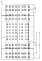
(実施形態1)
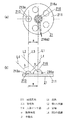
本実施形態の照明装置2は、図1乃至図3に示すように、オフィスや住宅等の天井材Cに取り付けられる天井埋め込み型ダウンライトであり、複数個の固体発光素子であるLED(図示せず)を有する複数(図示例では5つ)の発光部213と、人体から放射される熱線を検知するセンサ素子である後述の焦電型センサ素子が熱線の変化を検知すると人体検知信号を出力する人体センサ部216と、照明装置2の周囲の明るさを検出するための照度センサ部212(図4参照)と、人体センサ部216および照度センサ部212を駆動させるとともに人体センサ部216から出力される前記人体検知信号に基づいて発光部213が有する前記複数のLEDを点灯させる制御部22(図4参照)と、人体センサ部216および発光部213が一表面に実装される平面視略円形の板状の回路基板211とを備える。ここに、複数の発光部213は、人体センサ部216の周囲に配置されている。また、人体センサ部216、照度センサ部212、複数の発光部213および回路基板211よりLEDユニット21が構成される。
(Embodiment 1)
As shown in FIGS. 1 to 3, the
また、本実施形態の照明装置2は、図2および図3に示すように、金属(例えば、Al、Cuなどの熱伝導率の高い金属)により形成されLEDユニット21および制御部22を内部に収納する装置本体11と、円筒状部材により形成され且つ当該円筒状部材の下端部の外周全体から外方に延出した外鍔部12bを有し装置本体11に取付ねじ(図示せず)により取り付けられる円筒状の取付枠12と、装置本体11の外側における上端側に配設され装置本体11の内部に収納された制御部22へ給電するための端子台13と、取付枠12の外側に設けられ装置本体11および取付枠12を造営材である天井材Cに取り付けるための3つの取付ばね14とを備えている。ここにおいて、天井材Cには、平面視円形状の取付孔C2が貫設されており、取付枠12が外鍔部12bの上面を天井材Cの天井面C1における取付孔C2の周部に当接させた形で取付孔C2の内側に配置されるとともに、複数の取付ばね14が天井材Cにおける取付孔C2の周部上面に弾接することで、取付枠12および装置本体11が、天井材Cに固定される。
Moreover, as shown in FIGS. 2 and 3, the
装置本体11は、有底円筒状に形成され内部に制御部22を収納する第1収納部11aと、取付枠12の内側に嵌合する形状に形成され且つ第1収納部11aの下端側に固着されるとともにLEDユニット21が取付ねじ等により取着された金属板からなる支持基板11bとを備え、支持基板11bには、制御部22からLEDユニット21の発光部213に通電するための電線(図示せず)とLEDユニット21の人体センサ部216から出力される人体検知信号を伝送するための第1の信号線(図示せず)とLEDユニット21の照度センサ部212から出力される出力信号を伝送するための第2の信号線(図示せず)を挿通させるための貫通孔(図示せず)が設けられている。また、装置本体11には、透光性材料により形成された円板状のカバー15が、LEDユニット21を覆う形で取り付けられている。また、図2に示すように、装置本体11の内部におけるカバー15と回路基板211との間には、発光部213から放射された光を反射するための反射部材16が各発光部213の周囲を取り囲む形で配設されている。しかして、装置本体11は、回路基板211の前記一表面側に実装された人体センサ部216に熱線が入射可能であるとともに発光部213から放射される光を出射可能な形で回路基板211を支持している。
The apparatus
人体センサ部216は、図1に示すように、ポリエチレン樹脂により形成され外周面が略半球面状に形成されたレンズ216aを備えており、レンズ216aの内側に人体から放射される熱線を検知するセンサ素子である焦電型センサ素子(図示せず)が配設されている。なお、人体センサ部216は、前記焦電型センサ素子として、検知エリア内の人の微小な動きを検知することができるようにするために、センサエレメントを正方形の頂点位置に4個配列した形を有するクワッドタイプの焦電型センサ素子を用いている。ここに、レンズ216aは、フレネルレンズよりなる多数個のレンズ小体216a2の集合体からなる。人体センサ部216は、人体センサ部216の検知エリアに人が入ると、人体から放射される熱線を検知して人体検知信号を生成して後述の制御回路部221に出力する。
As shown in FIG. 1 , the human
照度センサ部212は、フォトダイオードおよびフォトダイオードからの信号を増幅するためのアンプ等が一体に設けられたモジュールであるフォトICダイオード(図示せず)からなり、レンズ216aの内側に配設されている。照度センサ部212は、照明装置2の周囲の照度に比例した大きさの出力信号Vs(図5参照)を生成して制御回路部221に出力する。
The
発光部213では、複数の前記LEDが直列に接続されてなる直列回路を複数有し、当該複数の直列回路が並列に接続されている。前記複数のLEDは、略半球面を有するレンズが一体に形成された平面視円形状のパッケージ213aに収納されている。
The
ここで、LEDユニット21は、図1に示すように、回路基板211の前記一表面における略中央部に人体センサ部216が配設され、当該人体センサ部216の周囲を囲むように5つの発光部213が配置されている。また、図1に示す例では、5つの発光部213が、人体センサ部216の周方向において等間隔であって、各発光部213の光軸(例えば、図1(b)のL3)に直交する方向における人体センサ部216の前記焦電型センサ素子の受光面の中心と前記各光軸との間の距離が同じ所定距離(例えば、20mm)となるように配置されている。なお、本実施形態の照明装置では、LEDユニット21の構成は、上述の構成に限らず、例えば、回路基板211に複数の発光部213のパッケージ213aそれぞれを挿入することができる複数の貫通孔(図示せず)を貫設して複数の発光部213が回路基板211の他表面側から複数の前記貫通孔それぞれに挿入された形で実装されてなるLEDユニット21を備える構成であってもよく、或いは、回路基板211に人体センサ部216のレンズ216aを挿入することができる貫通孔(図示せず)を貫設して人体センサ部216が回路基板211の前記他表面側から前記貫通孔に挿入された形で実装されてなるLEDユニット21を備える構成、或いは、回路基板211に人体センサ部216のレンズ216aおよび複数の発光部213のパッケージ213aを挿入することができる前記貫通孔を貫設して人体センサ部216および複数の発光部213のいずれもが回路基板211の前記他表面側から前記貫通孔に挿入された形で実装されてなるLEDユニット21を備える構成であってもよい。
Here, as shown in FIG. 1, the
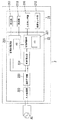
制御部22は、図4に示すように、人体センサ部216および照度センサ部212それぞれに前記第1の信号線および前記第2の信号線を介して電気的に接続された制御回路部221と、制御回路部221に電力を供給するための制御電源部224と、発光部213に前記電線を介して直流電流を出力する定電流電源部225と、交流電源ACから供給される交流電力を整流し且つ平滑化して制御電源部224および定電流電源部225それぞれに直流電力を供給する整流平滑部223と、交流電源ACと整流平滑部223との間に介挿され且つ交流電源ACから整流平滑部223に過電流が流れるのを防止するための入力保護部222とを備える。
As shown in FIG. 4, the
制御回路部221には、人体センサ部216から出力される前記人体検出信号および照度センサ部212の出力信号Vsに基づいて後述の消灯制御信号または点灯制御信号を出力するマイクロコンピュータ(以下、センサ制御用マイコンと称す)IC1を備えている。
The
制御電源部224は、整流平滑部223の出力端間に接続された第1のスイッチング素子(図示せず)と数kHzから数十kHzの高いスイッチング周波数に対応できる第1の高速ダイオード(図示せず)とからなる直列回路と、前記第1の高速ダイオードの両端間に接続されたインダクタ(図示せず)と平滑用コンデンサ(図示せず)とからなる直列回路と、前記第1のスイッチング素子に接続され前記第1のスイッチング素子のオン・オフ時間を制御するスイッチング電源用IC(図示せず)とからなる降圧チョッパ回路で構成されている。制御電源部224の一部を構成する前記平滑コンデンサの両端間には、制御回路部221が接続されており、制御電源部224から制御回路部221に直流電圧が出力される。
The control
定電流電源部225は、整流平滑部223の出力端間に接続された第2のスイッチング素子(図示せず)と第2の高速ダイオード(図示せず)とからなる直列回路と、前記第2の高速ダイオードの両端間に接続されたチョークコイルからなるインダクタ(図示せず)と平滑用コンデンサ(図示せず)とからなる直列回路と、前記第2のスイッチング素子に接続され前記第2のスイッチング素子のオン・オフ時間を制御するコントローラを構成するマイクロコンピュータ(以下、コントローラ用マイコンと称す)IC2とからなる降圧チョッパ回路で構成されている。定電流電源部225の一部を構成する前記平滑コンデンサの両端間には、発光部213を構成する前記複数のLEDの直列回路が接続されており、定電流電源部225から複数のLEDの直列回路に一定の直流電流を出力する。
The constant current
整流平滑部223は、交流電源ACから供給される交流電流を全波整流するダイオードブリッジ(図示せず)と、前記ダイオードブリッジの出力端間に接続され前記ダイオードブリッジから出力される脈流を平滑化するためのアルミ電解コンデンサからなる平滑用コンデンサ(図示せず)とから構成される。
The rectifying /
入力保護部222は、交流電源ACと整流平滑部223との間に介挿され、交流電源ACの出力端間に接続された電流ヒューズ(図示せず)およびフィルムコンデンサ(図示せず)からなる直列回路と、前記フィルムコンデンサの両端間に接続されたコンデンサ(図示せず)を含む雑音防止フィルタ回路(図示せず)とから構成される。
The
次に、本実施形態の照明装置2の動作について図5に基づいて説明する。
Next, operation | movement of the illuminating
人体センサ部216の前記検知エリアに人が入ると、人体センサ部216が前記検知エリアにおける人の人体から放射される熱線を検知して、制御回路部221のセンサ制御用マイコンIC1に前記人体検知信号を出力する。制御回路部221のセンサ制御用マイコンIC1は、人体センサ部216から出力される前記人体検知信号を受信する。また、センサ制御用マイコンIC1は、照度センサ部212からの出力信号Vsを継続的に受信しており、照度センサ部212からの出力信号Vsの大きさと予め設定されている点灯開始照度設定値(例えば、50ルクス)とを比較して、照度センサ部212からの出力信号Vsの大きさが前記点灯開始照度設定値よりも大きければ(図5のa点およびb点)、定電流電源部225に含まれるコントローラ用マイコンIC2に発光部213を消灯させるように指示するための消灯制御信号(Hi出力信号)を出力する。コントローラ用マイコンIC2は、センサ制御用マイコンIC1から出力された前記消灯制御信号を受信すると、定電流電源部225から発光部213への電流供給を遮断するように定電流電源部225を制御して、発光部213が有する前記複数のLEDを点灯しないようにする。ここに、定電流電源部225では、定電流電源部225に含まれる発振回路(図示せず)が発振を停止する。
When a person enters the detection area of the human
一方、センサ制御用マイコンIC1は、人体センサ部216から出力される前記人体検知信号を受信したときに、照度センサ部212からの出力信号Vsの大きさが前記点灯開始照度設定値よりも小さければ(図5のc点)、コントローラ用マイコンIC2に発光部213を点灯させるように指示するための点灯制御信号を出力する。コントローラ用マイコンIC2は、センサ制御用マイコンIC1から出力された前記点灯制御信号を受信すると、定電流電源部225から発光部213への通電を開始するように定電流電源部225を制御して、発光部213が有する前記複数のLEDを点灯させる。
On the other hand, when the sensor control microcomputer IC1 receives the human body detection signal output from the human
その後、人体センサ部216が前記検知エリアにいる人の人体から放射される熱線を検知しなくなると、人体センサ部216から制御回路部221に前記人体検知信号が出力されなくなる。ここで、センサ制御用マイコンIC1は、前記人体検知信号が制御回路部221に入力されなくなってから所定の点灯保持時間T1(例えば、1分)の経過後(図5のd点)、コントローラ用マイコンIC2に前記消灯制御信号を出力する。コントローラ用マイコンIC2は、センサ制御用マイコンIC1から出力された前記消灯制御信号を受信すると、定電流電源部225から発光部213への電流供給を遮断するように定電流電源部225を制御して発光部213が有する前記複数のLEDを消灯させる。
Thereafter, when the human
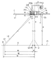
また、本実施形態の照明装置2では、図2に示すように、5つの発光部213それぞれが人体センサ部216から離間して配置され、床面F1上における人体センサ部216の検知エリアD(図6参照)が、発光部213から放射された光の放射光量が発光部213から放射された放射光量の最大値の半分以上となる光が配光される床面F1上の配光エリアS(図6参照)の全体を含むように、人体センサ部216が有する前記焦電型センサ素子の受光面の中心を通る回路基板211の前記一表面を含む平面の法線L1と人体センサ部216が有する前記焦電型センサ素子の前記受光面の中心と床面F1上における人体センサ部216の検知エリアDの外周とを結ぶ第1の直線L2とのなす角度である検知角度αが、発光部213の光軸L3と発光部213から放射され且つ放射光量が最大放射光量の半分となる光の放射方向に延長された第2の直線L4とのなす角度である発光部213の指向特性を表す半値角βよりも大きくなるように設定されている。また、本実施形態の照明装置2は、発光部213の周囲に反射部材16が設けられるとともに発光部213の下側にカバー15が設けられているので、前記半値角βは、発光部213から放射される光の反射部材16による反射およびカバー15を透過する際の屈折の影響を考慮した角度となる。一方、検知角度αは、人体センサ部216の下側に設けられているカバー15の影響をほとんど受けない。なお、図2に示す構成の照明装置2は、反射部材16およびカバー15を備えているが、これらは必ずしも設ける必要はなく、適宜設ければよい。
Moreover, in the illuminating
ところで、法線L1と床面F1との交点P1から人体センサ部216の床面F1上における検知エリアDの外周部までの距離は、当該距離をW1、人体センサ部216の床面F1からの高さ、発光部213の床面F1からの高さおよび天井面C1の床面F1からの高さが略同じとして、当該高さをHとすると、法線L1と第1の直線L2とのなす角度である検知角度αとの間で、下記(1)式で表される関係が成立する。
W1=tanα×H (1)式
また、法線L1と床面F1との交点P1から床面F1上における発光部213の配光エリアSの外周部までの距離W2は、当該距離をW2、発光部213の床面F1からの高さをH、および発光部213の光軸に直交する方向における人体センサ部216の前記焦電型センサ素子の受光面の中心と前記光軸との間の距離(以下、中心間距離と称す)をWとすると、発光部213の光軸L3と第2の直線L4とのなす角度である半値角βとの間で、下記(2)式で表される関係が成立する。下記(2)式において、W3=tanβ×Hは、発光部213の光軸L3と床面F1との交点P3から発光部213の配光エリアSの外周部までの距離に相当する。
W2=tanβ×H+W
=W3+W (2)式
ここで、床面F1上における検知エリアDを配光エリアSよりも広くするためには、法線L1と床面F1との交点P1から人体センサ部216の床面F1上における検知エリアDの外周部までの距離W1が、発光部213の光軸L3と床面F1との交点P3から発光部213の配光エリアSの外周部までの距離W2よりも大きくなるようにすればよい。従って、床面F1上における検知エリアDを配光エリアSよりも広くするためには、発光部213と人体センサ部216との中心間距離Wについて、下記(3)式の関係が成立すればよい。
W<H×[tanα−tanβ] (3)式
ここで、本実施形態の照明装置2が天井材Cに設けられた取付孔C2に取り付けられた例を図2に示す。図2に示した照明装置2は、外鍔部12bの外径φが約110mmとなるように形成された取付枠12に装置本体11が固定された形で取付孔C2に取り付けられており、発光部213と人体センサ部216との中心間距離Wが20mm、人体センサ部216の床面F1からの高さが床面F1から天井面C1までの高さH(図示例では、2.2m)と略同じ高さに設定されている。つまり、人体センサ部216および複数の発光部213は、床面F1からの高さが同じになるように配置されている。また、検知角度αが45.5度、半値角βが45度に設定されている。従って、法線L1と床面F1との交点P1から床面F1上における人体センサ部216の検知エリアDの外周部までの距離W1が2.24m、また、発光部213の光軸L3と床面F1との交点P3から床面F1上における発光部213の配光エリアSの外周部までの距離W3が2.2mであるから、法線L1と床面F1との交点P1から発光部213の配光エリアSの外周部までの距離W2が2.22mとなる。
By the way, the distance from the intersection P1 between the normal line L1 and the floor surface F1 to the outer peripheral portion of the detection area D on the floor surface F1 of the human
W1 = tan α × H (1) Formula Further, the distance W2 from the intersection P1 of the normal line L1 and the floor surface F1 to the outer peripheral portion of the light distribution area S of the
W2 = tan β × H + W
= W3 + W (2) Here, in order to make the detection area D on the floor surface F1 wider than the light distribution area S, the floor surface F1 of the human
W <H × [tan α−tan β] (3) Here, FIG. 2 shows an example in which the
しかして、図6に示すように、配光エリアS内に人体センサ部216の検知エリアDと重複しない領域がなく且つ配光エリアSに比べて検知エリアDが広くなるので、配光エリアSに人がいるときに発光部213が消灯することがなく、また、配光エリアSへ人が入ってから発光部213が点灯するまでの時間が短くすることができる。なお、図6におけるハッチングで示した部分は、人体センサ部216の前記焦電型センサ素子による検出ゾーンを表す。ここに、検出ゾーンは、人体センサ部216のレンズ216aを構成するレンズ小体216a2それぞれにより床面F1上に形成される前記焦電型センサ素子の受光面の像に相当する。ここで、実施形態1における検知エリアDは、床面F1上における焦電型センサ素子の複数の前記検出ゾーンのうち前記交点P1から最も離れた位置にある前記検出ゾーン内における前記交点P1から最も離れた点と前記交点P1とを結ぶ線を前記交点P1周りに回転させて得られる円の内側の領域に相当する。
Accordingly, as shown in FIG. 6, there is no region that does not overlap with the detection area D of the human
また、配光エリアSにおいて検知エリアDと重複しない領域が生じないように、人体センサ部216の前記焦電型センサ素子の前記受光面の床面F1に対する傾きを微調整する必要がないので、施工性が良いという利点がある。
Further, it is not necessary to finely adjust the inclination of the light receiving surface of the pyroelectric sensor element of the human
更に、装置本体11は、人体センサ部216および発光部213が実装された回路基板211を支持できる構造を有すればよいので、装置本体11に、人体センサ部216を保持するための複雑な構造を設ける必要がないから、装置本体11の構造を簡素化することができ、コスト上昇を抑制することができる。
Furthermore, since the apparatus
また、本実施形態では、発光部213が蛍光灯等に比べて発熱量の少ないLEDで構成されていることにより、発光部213が人体センサ部216に近接して配置されていながらも、人体センサ部216の前記人体検知信号の出力が、発光部213から放射される熱線の影響を受けることがなく、人体センサ部216の誤動作を低減できる。
Further, in the present embodiment, the
また、本実施形態の照明装置2では、検知角度αと、半値角βと、床面F1から人体センサ部216までの距離Hと、発光部213と人体センサ部216との中心間距離Wとの間に、(3)式で表される関係にあることにより、発光部213と人体センサ部216との中心間距離Wの設定が容易になるので、製造を容易にすることができる。
Moreover, in the illuminating
また、本実施形態の照明装置2では、5つの発光部213が互いに等間隔となるように配置されていることにより、配光エリアSが法線L1に対して略対称となるので、発光部213が点灯するタイミングを、配光エリアSへの人の侵入方向に関わらず同じにすることができる。
Further, in the
また、本実施形態では、人体センサ部216および発光部213が、一枚の回路基板211の同一表面である前記一表面上に実装されているので、床面F1から人体センサ部216までの高さと床面F1から発光部213までの高さとが異なる場合に比べて、検知エリアDおよび配光エリアSの設計が容易になるという利点がある。
In the present embodiment, since the human
また、本実施形態では、図1(b)に示すように、人体センサ部216の一部を構成するレンズ216aの側面が、第2の直線L4と交差しないような形状および大きさに形成されており、発光部213から配光エリアSに向かって放射される光をレンズ216aが遮らない。従って、発光部213の床面F1上における配光エリアSに照度ムラが生じるのを抑制することができる。
In the present embodiment, as shown in FIG. 1B, the side surface of the
なお、本実施形態における発光部213と人体センサ部216との中心間距離Wは、上述の例では、20mmに設定されているが、中心間距離Wは、上限である38.7mm以下であれば、検知角度α、半値角β、および人体センサ部216の床面F1からの高さ、発光部213の床面F1からの高さおよび天井面C1の床面F1からの高さが略同じとして、当該高さをHとしたときに、前記(3)式の関係が成立するように適宜設定することができる。
Note that the center-to-center distance W between the
(実施形態2)
本実施形態の照明装置2は、図7に示すように、オフィスや住宅等の天井材Cの天井面C1に木ねじ(図示せず)などの取付ねじにより取り付けられる照明装置2であり、複数(図示例では、6つ)の発光部213、人体センサ部216および照度センサ部(図示せず)を備えた長尺の第1のLEDユニット21Aと、複数の発光部213を備え第1のLEDユニット21Aの長手方向の両側それぞれに当該長手方向に沿って同じ数だけ複数(図示例では、3つ)配置された第2のLEDユニット21Bと、実施形態1と同様の回路構成を有する制御部(図示せず)とを備える。ここに、前記制御部は、第1のLEDユニット21Aの人体センサ部216および前記照度センサ部を駆動させるとともに人体センサ部216から出力される前記人体検知信号および前記照度センサ部から出力される出力信号に基づいて第1のLEDユニット21Aおよび第2のLEDユニット21Bの発光部213が有する前記複数のLEDを点灯させる。また、図8に示すように、第1のLEDユニット21Aおよび第2のLEDユニット21Bは、下面に開口窓を有する長尺の矩形箱状の装置本体111A内に収納されている。
(Embodiment 2)
As shown in FIG. 7, the
第1のLEDユニット21Aは、長尺の矩形板状に形成された回路基板211Aと、回路基板211Aの一表面において長手方向における略中央部に配設された人体センサ部216と、回路基板211Aの前記一表面において長手方向における人体センサ部216の両側それぞれに前記長手方向に沿って同じ数だけ複数(図示例では3つ)配置された発光部213とを備える。
The
人体センサ部216は、前記焦電型センサ素子と、ポリエチレン樹脂により形成され且つ前記焦電型センサ素子を覆う形で配設された平面視矩形状のレンズ216cとを備えている。なお、人体センサ部216は、レンズ216cを透過してきた熱線を反射する内部ミラー構造を有する。また、前記照度センサ部は、レンズ216cの内側に配設されている。
The human
第2のLEDユニット21Bは、長尺の矩形板状に形成された回路基板211Aと、回路基板211Aの前記一表面において長手方向に沿って配設された複数(図示例では、7つ)の発光部213とを備える。
The
ところで、本実施形態の照明装置2では、図8に示すように、床面F1上における人体センサ部216の検知エリアD(図9参照)が、複数の発光部213から放射される光の放射光量が複数の発光部213のうち人体センサ部216から最も離れた位置に配置された1つの発光部213から放射される光の放射光量の最大値の半分以上となる光が配光される床面F1上における配光エリアSの全体を含むように、人体センサ部216が有する前記焦電型センサ素子の前記受光面の中心を通る回路基板211Aの前記一表面を含む平面の法線である法線L1と人体センサ部216の前記焦電型センサ素子の前記受光面の中心と検知エリアDの外周とを結ぶ第1の直線L2とのなす角度である検知角度αが、人体センサ部216から最も離れた位置に配置された発光部213の光軸L3と、当該発光部213から放射され且つ放射光量が放射光量の最大値の半分となる光の放射方向に延長された第2の直線L4とのなす角度である半値角βよりも大きくなるように形成されている。
By the way, in the illuminating
本実施形態の照明装置2は、下面が開放した細長の直方体状の装置本体111Aを備えており、天井材Cに設けられた取付孔C2に取付ばね(図示せず)によって取り付けられ、人体センサ部216が床面F1から天井面C1までの高さHと略同じ高さに配置される。ここで、天井面C1に直交し且つ人体センサ部216の前記焦電型センサ素子の前記受光面の中心を通る法線L1と床面F1との交点P1から人体センサ部216の検知エリアDの外周部までの距離W1、および法線L1と床面F1との交点P1から発光部213の配光エリアSの外周部までの距離W2は、実施形態1で説明した前記(1)式および前記(2)式から求めることができる。
The illuminating
図7および図8に示した照明装置2では、装置本体111Aの長手方向の長さWaが、1245mmに設定されている。また、照明装置2は、天井面C1の床面F1からの高さHが2.2mの天井材Cに取り付けられる。
In the
また、回路基板211A,211Bそれぞれが、長手方向の長さWbが170mmとなるように形成され、隣接する回路基板211B同士の間隔Wc、および回路基板211Aと回路基板211Bとの間の間隔が10mmとなるように配置されている。また、各回路基板211A,211Bにおいて、複数の発光部213が、回路基板211Aの長手方向の両端と発光部213との間に生じる隙間Wdが5mmとなるように配設されている。
Each of the
ここで、複数の第2のLEDユニット21Bのうち第1のLEDユニット21Aから最も離れた位置に配置される第2のLEDユニット21Bでは、複数の発光部213のうち最も人体センサ部216から離れた位置に配置された発光部213の光軸に直交する方向における人体センサ部216の前記焦電型センサ素子の前記受光面の中心と前記光軸との間の距離(以下、中心間距離と称す)Wが、610mmとなるように設定されている。また、図7および図8に示した例では、検知角度αが65度、半値角βが55度に設定されている。
Here, among the plurality of
従って、図8に示す照明装置2では、発光部213と人体センサ部216との中心間距離Wが610mmであり、検知角度αが65度、半値角βが55度、天井面C1の床面F1からの高さHが2.2mであるから、法線L1と床面F1との交点P1から床面F1上における人体センサ部216の検知エリアDの外周部までの距離W1が4.72m、また、発光部213の光軸L3と床面F1との交点P3から床面F1上における発光部213の配光エリアSの外周部までの距離W3が3.14mとなるから、法線L1と床面F1との交点P1から床面F1上における発光部213の配光エリアSの外周部までの距離W2が3.75mとなる。
Therefore, in the
しかして、図9に示すように、配光エリアS内に人体センサ部216の検知エリアDと重複しない領域がなく且つ配光エリアSに比べて検知エリアDが広くなるので、配光エリアSに人がいるにも関わらず発光部213が消灯することがなく且つ配光エリアSに人が入ってから発光部213が点灯するまでの時間が短い適切な検知エリアDを確保することができる。なお、図9におけるハッチングで示した矩形状の部分は、人体センサ部216の前記焦電型センサ素子による検出ゾーンを表す。ここで、実施形態2における検知エリアDは、床面F1上に形成される複数の前記検出ゾーンから構成される集合体における、複数の前記検出ゾーンと、互いに隣接する前記検出ゾーンの間の領域とを合わせた領域に相当する。
Therefore, as shown in FIG. 9, there is no region that does not overlap with the detection area D of the human
また、本実施形態では、図7に示すように、人体センサ部216の一部を構成するレンズ216cが、第2の直線L4と交差しないような形状および大きさに形成されており、人体センサ部216に隣接する発光部213から当該発光部213の配光エリアSに向かって放射される光を遮らない。従って、床面F1上における配光エリアSに照度ムラが生じるのを抑制することができる。
Further, in the present embodiment, as shown in FIG. 7, the
なお、本実施形態における発光部213と人体センサ部216との中心間距離Wは、上述の例では、610mmに設定されているが、中心間距離Wは、上限である1575mm以下であれば、検知角度α、半値角β、および人体センサ部216の床面F1からの高さ、発光部213の床面F1からの高さおよび天井面C1の床面F1からの高さが略同じとして、当該高さをHとしたときに、前記(3)式の関係が成立するように適宜設定することができる。
Note that the center-to-center distance W between the
また、実施形態2で説明した照明装置2では、発光部213のみを備えた第2のLEDユニット21Bを複数備える例について説明したが、これに限定されるものではなく、例えば、人体センサ部216と複数の発光部213とを備える1つのLEDユニット(図示せず)を配置するものであってもよい。
Moreover, in the illuminating
(実施形態3)
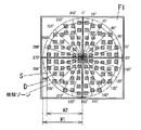
本実施形態の照明装置2は、図10および図11に示すように、オフィスや住宅等の天井材Cの天井面C1に木ねじ(図示せず)などの取付ねじにより取り付けられる照明装置2であり、複数(図示例では、8つ)の発光部213および1つの人体センサ部216を備えた平面視正方形状の第1のLEDユニット21Aと、複数(図示例では、9つ)の発光部213を備え第1のLEDユニット21Aの周囲を囲む形で配置された平面視正方形状の8つの第2のLEDユニット21Bと、平面視正方形状に形成され下面に開口部を有し且つ第1のLEDユニット21Aおよび第2のLEDユニット21Bが内部に収納される装置本体111Bと、装置本体111Bの下面の開口部を覆う形で装置本体111Bに取り付けられる透光性材料からなる矩形板状のカバー(図示せず)と、実施形態1と同様の回路構成を有する制御部(図示せず)とを備える。ここに、前記制御部は、第1のLEDユニット21Aの人体センサ部216および照度センサ部(図示せず)を駆動させるとともに人体センサ部216から出力される前記人体検知信号および前記照度センサ部から出力される出力信号に基づいて第1のLEDユニット21Aおよび第2のLEDユニット21Bの発光部213が有する前記複数のLEDを点灯させる。なお、装置本体111Bの内部における前記カバーと、第1のLEDユニット21Aの一部を構成する後述の回路基板211Aおよび第2のLEDユニット21Bの一部を構成する回路基板211Bとの間には、発光部213それぞれの周囲を取り囲む形で配設され発光部213それぞれから放射された光を反射する複数の反射部材16(図11参照)が配設されている。また、本実施形態の照明装置2の装置本体111Bは、図11に示すように、一辺の長さWeの平面視正方形状に形成され前記制御部を収納する第1収納室111B1と、一辺の長さが第1収納室111B1の一辺の長さよりも長い平面視正方形状に形成され且つ第1収納室111B1の下側に第1収納室111B1と連続一体に設けられ第1のLEDユニット21Aおよび第2のLEDユニット21Bを収納する第2収納室111B2とから構成されている。
(Embodiment 3)
As shown in FIGS. 10 and 11, the
第1のLEDユニット21Aは、平面視正方形の板状に形成された回路基板211Aと、回路基板211Aの一表面における略中央部に配設された人体センサ部216と、回路基板211Aの前記一表面における人体センサ部216の周囲に配置された複数(図示例では、8つ)の発光部213とを備える。
The
人体センサ部216は、実施形態1で説明した人体センサ部216と同様に、前記焦電型センサ素子(図示せず)と、平面視円形に形成され且つ前記焦電型センサ素子を覆う形で配設されたレンズ216aとを備えている。
Similar to the human
第2のLEDユニット21Bは、平面視正方形の板状に形成された回路基板211Bと、回路基板211Bの一表面に等間隔に配設された複数(図示例では、9つ)の発光部213とを備える。
The
ところで、本実施形態の照明装置2では、図11に示すように、床面F1上における人体センサ部216の検知エリアDが、複数の発光部213から放射される光の放射光量が複数の発光部213のうち人体センサ部216から最も離れた位置に配置された1つの発光部213から放射される光の放射光量の最大値の半分以上となる光が配光される床面F1上における配光エリアSの全体を含むように、人体センサ部216が有する前記焦電型センサ素子の受光面の中心を通る回路基板211Aの一表面を含む平面の法線である法線L1と人体センサ部216の前記焦電型センサ素子の受光面の中心と検知エリアDの外周とを結ぶ第1の直線L2とのなす角度である検知角度αが、人体センサ部216から最も離れた位置に配置された発光部213の光軸L3と、当該発光部213から放射され且つ放射光量が放射光量の最大値の半分となる光の放射方向に延長された第2の直線L4とのなす角度である半値角βよりも大きくなるように形成されている。また、本実施形態の照明装置2は、発光部213の周囲に反射部材16が設けられるとともに発光部213の下側に前記カバーが設けられているので、半値角βは、発光部213から放射される光の反射部材16による反射および前記カバーを透過する際の屈折の影響を考慮した角度となる。なお、図11に示す構成の照明装置2では、反射部材16および前記カバーが設けられているが必須ではない。
By the way, in the illuminating
本実施形態の照明装置2は、平面視正方形状の装置本体111Bを備えており、天井材Cの天井面C1に取り付けられ、人体センサ部216が床面F1から天井面C1までの高さHと略同じ高さに配置される。ここで、天井面C1に直交し且つ人体センサ部216の前記焦電型センサ素子の前記受光面の中心を通る法線L1と床面F1との交点P1から人体センサ部216により床面F1上に形成される検知エリアDの外周部までの距離W1、および法線L1と床面F1との交点P1から発光部213により前記床面上に形成される配光エリアSの外周部までの距離W2は、実施形態1で説明した前記(1)式および前記(2)式から求めることができる。
The
図11に示した照明装置2では、装置本体111Bの第1収納室111B1の一辺の長さWeが、500mmに設定されている。また、照明装置2は、天井面C1の床面F1からの高さHが2.2mの天井材Cに取り付けられる。なお、図11に示した照明装置2では、天井面C1と照明装置2の下面との間の距離Wfが0.1mとなるように設定されている。
In the
なお、図10に示した例では、回路基板211A,211Bの一辺の長さが、100mmに設定されている。ここで、8つの第2のLEDユニット21Bのうち平面視正方形状の第1のLEDユニット21Aの対角方向に配置された第2のLEDユニット21Bでは、複数の発光部213のうち人体センサ部216から最も離れた位置に配置された発光部213の光軸に直交する方向における人体センサ部216の前記焦電型センサ素子の受光面の中心と前記光軸との間の距離(以下、中心間距離と称す)Wが、250mmとなるように設定されている。また、検知角度αが45.5度、半値角βが40度に設定されている。
In the example shown in FIG. 10, the length of one side of the
図11に示す本実施形態の照明装置2では、発光部213と人体センサ部216との中心間距離Wが250mmであり、検知角度αが45.5度、半値角βが40度、天井面C1の床面F1からの高さHが2.2mであるから、法線L1と床面F1との交点P1から人体センサ部216の検知エリアDの外周部までの距離W1が2.24m、また、発光部213の光軸L3と床面F1との交点P3から前記人体センサ部216から最も離れた位置に配置された発光部213の配光エリアSの外周部までの距離W3が1.85mとなるから、法線L1と床面F1との交点P1から前記人体センサ部216から最も離れた位置に配置された発光部213の配光エリアSの外周部までの距離W2が2.10mとなる。
In the illuminating
しかして、前記人体センサ部216から最も離れた位置に配置された発光部213の配光エリアS内に人体センサ部216の検知エリアDと重複しない領域がなく、且つ配光エリアSに比べて検知エリアDが広くなるので、配光エリアSに人がいるにも関わらず発光部213が消灯することがなく且つ配光エリアSに人が入ってから発光部213が点灯するまでの時間が短い適切な検知エリアDを確保することができる。
Accordingly, there is no region that does not overlap with the detection area D of the human
なお、本実施形態における発光部213と人体センサ部216との中心間距離Wは、上述の例では、250mmに設定されているが、中心間距離Wは、上限である390mm以下であれば、検知角度α、半値角β、および人体センサ部216の床面F1からの高さ、発光部213の床面F1からの高さおよび天井面C1の床面F1からの高さが略同じとして、当該高さをHとしたときに、前記(3)式の関係が成立するように適宜設定することができる。
Note that the center-to-center distance W between the
また、実施形態3で説明した照明装置2では、発光部213のみを備えた第2のLEDユニット21Bを複数備える例について説明したが、これに限定されるものではなく、例えば、人体センサ部216と複数の発光部213とが配置されてなる1つのLEDユニット(図示せず)を用いるものであってもよい。
Moreover, in the illuminating
また、前述の各実施形態では、発光部213がLEDからなる固体発光素子を備える例について説明したが、これに限定されるものではなく、例えば、有機EL素子等からなる固体発光素子を備えるものであってもよい。
Further, in each of the above-described embodiments, the example in which the
2 照明装置
11,111A,111B 装置本体
22 制御部
211,211A,211B 回路基板
213 発光部
216 人体センサ部
α 検知角度
β 半値角
D 検知エリア
S 配光エリア
F1 床面
L1 法線
L2 第1の直線
L3 光軸
L4 第2の直線
2
Claims (3)
W<H×[tanα−tanβ]
が成立するように、前記人体センサ部および前記発光部が配置されてなることを特徴とする請求項1記載の照明装置。 The human body sensor unit and the plurality of light emitting units are arranged so that the height from the floor surface is the same, and the light emitting unit arranged at a position farthest from the human body sensor unit For the center-to-center distance, which is the distance between the center of the light receiving surface of the sensor element of the human body sensor unit and the optical axis in the direction orthogonal to the optical axis, the center-to-center distance is W, and the human body sensor unit When the height from the floor is H, the detection angle is α, and the half-value angle is β, the relational expression W <H × [tan α−tan β]
The lighting device according to claim 1, wherein the human body sensor unit and the light emitting unit are arranged so that
Priority Applications (3)
| Application Number | Priority Date | Filing Date | Title |
|---|---|---|---|
| JP2009151634A JP5379575B2 (en) | 2009-06-25 | 2009-06-25 | Lighting device |
| EP10165873.0A EP2268106B1 (en) | 2009-06-25 | 2010-06-14 | Illumination device |
| CN2010102143251A CN101936484B (en) | 2009-06-25 | 2010-06-25 | Illumination device |
Applications Claiming Priority (1)
| Application Number | Priority Date | Filing Date | Title |
|---|---|---|---|
| JP2009151634A JP5379575B2 (en) | 2009-06-25 | 2009-06-25 | Lighting device |
Publications (2)
| Publication Number | Publication Date |
|---|---|
| JP2011009082A JP2011009082A (en) | 2011-01-13 |
| JP5379575B2 true JP5379575B2 (en) | 2013-12-25 |
Family
ID=43012167
Family Applications (1)
| Application Number | Title | Priority Date | Filing Date |
|---|---|---|---|
| JP2009151634A Expired - Fee Related JP5379575B2 (en) | 2009-06-25 | 2009-06-25 | Lighting device |
Country Status (3)
| Country | Link |
|---|---|
| EP (1) | EP2268106B1 (en) |
| JP (1) | JP5379575B2 (en) |
| CN (1) | CN101936484B (en) |
Families Citing this family (6)
| Publication number | Priority date | Publication date | Assignee | Title |
|---|---|---|---|---|
| JP5877575B2 (en) * | 2009-07-31 | 2016-03-08 | 東芝ライテック株式会社 | lighting equipment |
| JP6113417B2 (en) | 2011-04-22 | 2017-04-12 | アイリスオーヤマ株式会社 | LED lamp |
| JP5743714B2 (en) * | 2011-05-26 | 2015-07-01 | 三菱電機株式会社 | LED lighting fixtures |
| AT14574U1 (en) * | 2014-11-06 | 2016-01-15 | Tridonic Gmbh & Co Kg | Sensor for motion detection |
| JP6418450B2 (en) * | 2015-02-10 | 2018-11-07 | パナソニックIpマネジメント株式会社 | Lighting device and lighting device |
| JP2021120728A (en) * | 2020-01-31 | 2021-08-19 | カシオ計算機株式会社 | Fluorescence emission device, light source device and projection device |
Family Cites Families (8)
| Publication number | Priority date | Publication date | Assignee | Title |
|---|---|---|---|---|
| JPH09161515A (en) * | 1995-05-26 | 1997-06-20 | Matsushita Electric Works Ltd | Local illumination device |
| JP2001325810A (en) * | 2000-05-16 | 2001-11-22 | Yamada Shomei Kk | Lighting fixture |
| JP3879389B2 (en) | 2000-11-17 | 2007-02-14 | 松下電工株式会社 | lighting equipment |
| TW515107B (en) * | 2001-12-25 | 2002-12-21 | Solidlite Corp | Power-saving light-emitting diode lamp |
| CN2578671Y (en) * | 2002-10-22 | 2003-10-08 | 刘为革 | Pyroelectric infrared induced lamps |
| KR200334515Y1 (en) * | 2003-08-18 | 2003-11-28 | 황윤규 | Automatic control energy savimg lamp builted in combination sensor |
| JP2005235398A (en) | 2004-02-17 | 2005-09-02 | Matsushita Electric Works Ltd | Lighting fixture |
| US7327254B2 (en) * | 2005-02-02 | 2008-02-05 | Chen Kai-Po | Bulb with sensing function |
-
2009
- 2009-06-25 JP JP2009151634A patent/JP5379575B2/en not_active Expired - Fee Related
-
2010
- 2010-06-14 EP EP10165873.0A patent/EP2268106B1/en not_active Not-in-force
- 2010-06-25 CN CN2010102143251A patent/CN101936484B/en not_active Expired - Fee Related
Also Published As
| Publication number | Publication date |
|---|---|
| CN101936484B (en) | 2012-10-24 |
| JP2011009082A (en) | 2011-01-13 |
| CN101936484A (en) | 2011-01-05 |
| EP2268106B1 (en) | 2018-08-08 |
| EP2268106A3 (en) | 2015-09-09 |
| EP2268106A2 (en) | 2010-12-29 |
Similar Documents
| Publication | Publication Date | Title |
|---|---|---|
| JP4786750B2 (en) | Lighting device | |
| JP5379575B2 (en) | Lighting device | |
| JP5637344B2 (en) | Lamp apparatus and lighting apparatus | |
| JP5549926B2 (en) | Lamp with lamp and lighting equipment | |
| JP4756346B2 (en) | LED lighting fixtures and LED emergency lights | |
| JP5253552B2 (en) | Lighting device | |
| JP2015111539A (en) | Light source unit and lighting device | |
| JP2009104913A (en) | Lighting apparatus, and emergency light | |
| JP4902006B2 (en) | Lighting device | |
| JP6774171B2 (en) | Lighting device including light emitting unit and light emitting unit | |
| JP5918835B2 (en) | Lighting device | |
| JP5523140B2 (en) | lighting equipment | |
| JP6761248B2 (en) | Lighting device | |
| JP5116865B2 (en) | Lighting device | |
| JP2010123369A (en) | Led luminaire | |
| JP6268645B2 (en) | Illumination light source and illumination device | |
| JP5559649B2 (en) | Lighting device | |
| JP6340724B2 (en) | Light source unit and lighting apparatus | |
| JP2014220160A (en) | Light source for illumination and lighting device | |
| JP5127053B2 (en) | lighting equipment | |
| JP2018018787A (en) | Lighting device | |
| JP2012084328A (en) | Lighting system | |
| JP7065324B2 (en) | lighting equipment | |
| JP2022020707A (en) | Lighting fixture | |
| JP5655170B2 (en) | Lighting device |
Legal Events
| Date | Code | Title | Description |
|---|---|---|---|
| A711 | Notification of change in applicant |
Free format text: JAPANESE INTERMEDIATE CODE: A712 Effective date: 20120118 |
|
| A621 | Written request for application examination |
Free format text: JAPANESE INTERMEDIATE CODE: A621 Effective date: 20120210 |
|
| A977 | Report on retrieval |
Free format text: JAPANESE INTERMEDIATE CODE: A971007 Effective date: 20130322 |
|
| A131 | Notification of reasons for refusal |
Free format text: JAPANESE INTERMEDIATE CODE: A131 Effective date: 20130326 |
|
| A521 | Request for written amendment filed |
Free format text: JAPANESE INTERMEDIATE CODE: A523 Effective date: 20130527 |
|
| TRDD | Decision of grant or rejection written | ||
| A01 | Written decision to grant a patent or to grant a registration (utility model) |
Free format text: JAPANESE INTERMEDIATE CODE: A01 Effective date: 20130903 |
|
| A61 | First payment of annual fees (during grant procedure) |
Free format text: JAPANESE INTERMEDIATE CODE: A61 Effective date: 20130927 |
|
| R150 | Certificate of patent or registration of utility model |
Ref document number: 5379575 Country of ref document: JP Free format text: JAPANESE INTERMEDIATE CODE: R150 Free format text: JAPANESE INTERMEDIATE CODE: R150 |
|
| LAPS | Cancellation because of no payment of annual fees |