JP5378923B2 - Suspended structure - Google Patents
Suspended structure Download PDFInfo
- Publication number
- JP5378923B2 JP5378923B2 JP2009215931A JP2009215931A JP5378923B2 JP 5378923 B2 JP5378923 B2 JP 5378923B2 JP 2009215931 A JP2009215931 A JP 2009215931A JP 2009215931 A JP2009215931 A JP 2009215931A JP 5378923 B2 JP5378923 B2 JP 5378923B2
- Authority
- JP
- Japan
- Prior art keywords
- uppermost
- floor
- string
- beams
- floor slab
- Prior art date
- Legal status (The legal status is an assumption and is not a legal conclusion. Google has not performed a legal analysis and makes no representation as to the accuracy of the status listed.)
- Active
Links
Images


Abstract
Description
本発明は、屋上緑化を目的とした吊り構造の構造物に関するものである。 The present invention relates to a suspended structure for rooftop greening.
従来、構造物の構造として、地震や強風等に対抗するため、吊り床構造の構造物が知られている(特許文献1参照)。 Conventionally, as a structure of a structure, a structure having a suspended floor structure is known in order to resist earthquakes, strong winds, and the like (see Patent Document 1).
また、近年、温暖化予防のため、ビル等の構造物の屋上を緑化する屋上緑化が知られている(特許文献2参照)。 In recent years, rooftop greening is known in which the rooftop of a structure such as a building is greened to prevent global warming (see Patent Document 2).
しかしながら、このような吊り構造の構造物は、各階の床はその階よりも上方に位置する柱に連結されたワイヤーによって吊り下げられるため、最上階(屋上階)の上方に柱が突出した状態となっており、その柱を有効活用されないままであった。 However, in the structure of such a suspended structure, since the floor of each floor is suspended by a wire connected to a pillar located above the floor, the pillar protrudes above the top floor (the rooftop floor). The pillar has not been effectively utilized.
また、温暖化防止策として行う屋上緑化では、緑化施工に伴い、構造物の重量が増加する、という問題があった。 In addition, rooftop greening performed as a global warming prevention measure has a problem that the weight of the structure increases with the greening construction.
本発明は、上述した事情に鑑みてなされたもので、その目的は、構造物の重量増加を抑制しながら、最上階の床よりも上方を緑化することができる吊り構造の構造物を提供することにある。 The present invention has been made in view of the above-described circumstances, and an object of the present invention is to provide a suspended structure that can be greened above the floor of the top floor while suppressing an increase in the weight of the structure. There is.
[1]立設されている複数の柱と、隣接する前記柱間に架け渡され、各階毎に配置された梁と、各階を構成する床版と、上端が前記柱に取り付けられ、下端が各階を構成する前記床版に取り付けられ、前記梁および前記床を吊り下げて支持する吊り材と、を備えた構造物であって、前記柱は、最上階の前記床版よりも上方に突出した最上方柱部を有し、前記柱の前記最上方柱部は、最上階の前記床版よりも上方に配置された最上方梁が架け渡され、隣接する前記最上方梁間に紐状体が張り渡され、前記紐状体に植物が支持されていることを特徴とする吊り構造の構造物。 [1] A plurality of standing pillars, beams arranged between adjacent pillars, arranged on each floor, a floor slab constituting each floor, an upper end attached to the pillar, and a lower end A suspension member that is attached to the floor slab constituting each floor, and that supports the beam and the floor by suspending the floor, wherein the pillar projects upward from the floor slab of the top floor The uppermost column portion of the column is bridged by the uppermost beam disposed above the floor slab on the uppermost floor, and a string-like body is provided between the adjacent uppermost beams. Is suspended and the plant is supported by the string-like body.
[2]前記最上方梁には、植物が栽培されているプランターが支持されていることを特徴とする前項1記載の吊り構造の構造物。 [2] The suspended structure according to item 1 above, wherein the uppermost beam supports a planter in which plants are cultivated.
[3]前記吊り材は、PC鋼材であることを特徴とする前項1記載の吊り構造の構造物。 [3] The suspension structure according to item 1 above, wherein the suspension material is a PC steel material.
[4]前項1〜3のいずれか1項に記載の前記構造物は、駐車場であることを特徴とする吊り構造の構造物。 [4] The suspension structure according to any one of items 1 to 3, wherein the structure is a parking lot.
前項[1]の発明によると、前記柱に最上階の前記床版よりも上方に突出した最上方柱部に、最上階の前記床版よりも上方に配置された最上方梁を架け渡し、隣接する前記最上方梁間に紐状体を張り渡し、前記紐状体に植物を支持したため、最上階の床版を支持するため柱や梁を、屋上緑化に必要な構造物の柱や梁として利用することで、構造物の重量増加を抑制ながら、最上階の床よりも上方を緑化することができる。 According to the invention of [1], the uppermost beam disposed above the floor slab on the uppermost floor is bridged to the uppermost pillar portion protruding above the floor slab on the uppermost floor to the pillar, Since the string-like body is stretched between the adjacent uppermost beams and the plant is supported by the string-like body, the pillars and beams are used as the pillars and beams of the structure necessary for rooftop greening to support the floor slab on the uppermost floor. By using it, the upper part of the floor can be greened while suppressing an increase in the weight of the structure.
前項[2]の発明によると、前記最上方梁に植物が栽培されているプランターを支持したため、最上階に緑化を干渉させず、最上階の床よりも上方のみを緑化させることができる。 According to the invention of the preceding item [2], since the planter on which the plant is cultivated is supported on the uppermost beam, the uppermost floor can be greened without interfering with the greening on the uppermost floor.
前項[3]の発明によると、吊り材をPC鋼材としたため、重量を軽減でき、設置面積も小さくできる。これにより、空間性を高めることができる。 According to the invention of the preceding item [3], since the suspension material is a PC steel material, the weight can be reduced and the installation area can be reduced. Thereby, spatiality can be improved.
前項[4]の発明によると、前項1〜4のいずれか1項に記載の前記構造物を駐車場としたため、この駐車場について上述した構造物の効果を奏することができる。 According to the invention of the preceding item [4], since the structure according to any one of the preceding items 1 to 4 is used as a parking lot, the effects of the structure described above for the parking lot can be achieved.
次に、本発明の一実施形態について図1〜図4を参照して以下に説明する。 Next, an embodiment of the present invention will be described below with reference to FIGS.
図1は、本発明の一実施形態にかかる吊り構造の構造物の正面図である。図2は、同構造物の骨組みを示した斜視説明図である。図3は、同構造物の緑化構成を示した斜視説明図である。図4は、同構造物の横梁の内部構成を示した拡大図である。 FIG. 1 is a front view of a suspended structure according to an embodiment of the present invention. FIG. 2 is a perspective explanatory view showing the framework of the structure. FIG. 3 is a perspective explanatory view showing a greening structure of the structure. FIG. 4 is an enlarged view showing the internal configuration of the cross beam of the structure.
図1に示すように、この実施形態にかかる吊り構造の構造物1は、6階建ての駐車場になっており、下方から1階、2階、3階、4階、5階、最上階(屋上)となっている。 As shown in FIG. 1, the suspended structure 1 according to this embodiment is a six-story parking lot. From the bottom, the first floor, the second floor, the third floor, the fourth floor, the fifth floor, the top floor (Rooftop).
図1〜図2に示すように、この吊り構造の構造物1は、柱10と、梁20と、床版30と、吊り材40と、から構成されている。
As shown in FIGS. 1 to 2, the structure 1 having the suspension structure includes a
図1〜図2に示すように、柱10・・・は、地盤Gに埋設されているフーチング11・・・の上に立設されている。このフーチング11・・・上に立設された柱10・・・は、所定の間隔をおきながら複数本立設されている。また、この柱10・・・は、最上階(屋上)の床よりも上方に突出した最上方柱部10a・・・を有している。
この柱10・・・は、例えば角柱形状に形成されている。またこの柱10・・・の全高は、例えば全高19.5mに設定されている。
As shown in FIGS. 1 to 2, the
The
次に、梁について説明する。 Next, the beam will be described.
図1〜図2に示すように、隣接する柱10・・・間には、各階毎に所定数の梁20・・・が接続されている。この梁20・・・は、縦方向に延びる縦梁21・・・と、横方向に延びる横梁22・・・とから構成されている。
As shown in FIGS. 1 to 2, a predetermined number of
まず、1〜5階までの梁について説明する。 First, the beams from the first to the fifth floor will be described.
図2に示すように、この縦梁21・・・は、縦方向に水平に延び隣接する柱10・・・間を架け渡し、柱10・・・に接続されている。さらに、この縦梁21・・・は、柱10・・・間以外にも、横梁22・・・に直交する位置に配置され、横梁22・・・間を架け渡し、横梁22・・・と交差するように連結されている。
As shown in FIG. 2, the
また、横梁22・・・は、横方向に水平に延び隣接する柱10・・・間を架け渡し、柱10・・・に接続されている。さらに、この横梁22・・・は、柱10・・・間以外にも、縦梁21・・・に直交する位置に配置され、縦梁21・・・間を架け渡し、縦梁21・・・と交差するように連結されている。
Further, the
以上のようにして、縦梁21・・・および横梁22・・・すなわち梁20・・・は、各階(2階〜5階)の所定箇所に複数配置されている。
As described above, a plurality of the
次に、最上階の床よりも上方に配置された梁について説明する。 Next, the beam arranged above the floor on the top floor will be described.
図3に示すように、隣接する最上方柱部10a・・・間には、最上方梁20a・・・が接続されている。この最上方梁20a・・・は、縦方向に延びる最上方縦梁21a・・・と、横方向に延びる最上方横梁22a・・・と、から構成されている。
As shown in FIG. 3, uppermost beams 20a... Are connected between adjacent uppermost
この最上方縦梁21a・・・は、縦方向に水平に延び、隣接する最上方柱部10a・・・間を架け渡し、最上方柱部10a・・・に接続されている。さらに、この最上方縦梁21a・・・は、最上方柱部10a・・・間以外にも、最上方横梁22a・・・に直交する位置に配置され、最上方横梁22a・・・間を架け渡し、最上方横梁22a・・・と交差するように連結されている。
The uppermost
また最上方横梁22a・・・は、横方向に水平に延び隣接する最上方柱部10a・・・間を架け渡し、最上方柱部10a・・・に接続されている。さらに、この最上方横梁22a・・・は、最上方柱部10a・・・間以外にも、最上方縦梁21aに直交する位置に配置され、最上方縦梁21a・・・間を架け渡し、最上方縦梁21a・・・と交差するように連結されている。
Further, the uppermost
以上のようにして、最上方縦梁21a・・・および最上方横梁22a・・・すなわち最上方梁20a・・・は、最上階の梁20・・・とその上面に載置される床版30・・・とかなる床よりも上方の所定箇所に配置されている。
As described above, the
また、最上階の床よりも上方に存在する最上方横梁22a・・・の上面には、プランター222・・・が載置され、手摺221・・・が固定されている。プランター222には、例えば植物用土肥が敷き詰められ、そこに植物Pが栽培されている。手摺221は、プランター222を管理する際に転落等防止のために、最上方横梁22aに沿って固定されている。また、最上方縦梁21a・・・の上面には、最上方縦梁21a・・・に沿って手摺211・・・が固定されている。
Further,
この最上方横梁22aおよび最上方縦梁21aは、最上方横梁22aおよび最上方縦梁21aの上面を人が渡れるぐらいの幅を有していることが好ましい。そのため、最上方横梁22aおよび最上方縦梁21aは、例えば幅1000〜1500mmが好ましく、この実施形態では幅1300mmに設定されたものを採用している。
The uppermost
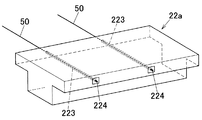
図4に示すように、最上方横梁22aの内部には、紐状体50を挿入するための挿入管部223,223が形成されている。この挿入管部223,223は、最上方横梁22aの長手方向に直交する方向に挿入管部223,223が形成されている。この挿入管部223は、直径40〜100mmのものが好ましく、この実施形態では、直径50mmに形成されている。
As shown in FIG. 4,
最上方横梁22a・・・と最上方縦梁21a・・・とで囲まれた内側には、緑化ユニット部60・・・が形成されている。この緑化ユニット部60・・・は、最上階の床よりも上方に複数存在する。この緑化ユニット部60は、紐状体50と、養生ネット51と、植物Pと、から構成されている。
On the inner side surrounded by the uppermost
紐状体50・・・は、隣接する最上方横梁22a間に数本(この実施形態では6本)張り渡され、最上方横梁22aの挿入管部223に固定されている。すなわち、この紐状体50の一端部は、最上方横梁22aの挿入管部223内に挿入され、その挿入管部223の内部で固定されている。また紐状体50の他端部は、平行に配された隣接する最上方横梁22aの外部に露出されている紐状体定着部224に固定されている。
The string-
紐状体50は、例えばワイヤー、ロープ、エクスパンドメタル、グレーチング、ネット等が好ましく、この実施形態では、ワイヤーを採用している。この紐状体50は、直径12〜30mm、長さ17000〜35000mmが好ましく、この実施形態では直径18mm、長さ17000mのものを採用している。
The string-
この各緑化ユニット部60・・・の各紐状体50・・・には、養生ネット51が支持されている。また、この養生ネット51には植物Pが誘引され栽培されている。この植物Pは、例えば蔓植物が採用されている。
A curing
また、柱10・・・および最上方柱部10aと、梁20・・・および最上方梁20aとが交わる箇所には、上部定着突起12が形成されている。
次に、床版について説明する。
Further, an
Next, the floor slab will be described.
図2、図3に示すように、設置予定階の1階部分と最上階の床より上方に存在する梁20を除く、縦梁21および横梁22からなる梁20の上面には、床版30が敷設されている。この床版30によって各階(床)は、形成されている。
As shown in FIGS. 2 and 3, a
また、この床版30には、転落防止壁225と下部定着突起212とが形成されている。
Further, the
転落防止壁225は、自動車等が誤って構造物1内部側(駐車場)から、構造物1の外部側に誤発進した際の転落(落下)を防止するため、構造物1の外周縁を囲うように適宜配設されている。この転落防止壁225は、厚さ100〜250mm、高さ600〜1100mm、幅1000〜2000mmのものが好ましく、この実施形態では厚さ200mm、高さ1100mm、幅1500mmのものを採用している。
The
また、縦梁21と横梁22とが連結する箇所であって、この連結する箇所の上階の上部定着突起12の斜め下方位置には、下部定着突起212が形成されている。
In addition, a
次に吊り材40ついて説明する。
Next, the
図1〜図3に示すように、吊り材40の上端および下端には、構造物1に緊張状態で接続するための固定具41が固着されている。
As shown in FIGS. 1 to 3, a fixture 41 for connecting to the structure 1 in a tension state is fixed to an upper end and a lower end of the
吊り材40の上端の固定具41は、吊り材40の設置予定階の上階の上部定着突起12に固定され、吊り材40の下端の固定具41は、吊り材40の設置予定階に形成された下部定着突起212に固定されている。この上端と下端とが固定された吊り材40は、斜め姿勢のまま緊張状態で固定されている。これによって、梁20上に敷設された床版30すなわち床は、吊り下げられている。
The fixing tool 41 at the upper end of the hanging
このような接続構成の吊り材40は、各階ごとに複数本取り付けられている。中央の柱10・・・では、2本の吊り材40,40が左右両側から交差するように取り付けられている。また、左右両端の柱10・・・では、各1本ずつ吊り材40が取り付けられている。
A plurality of
吊り材40は、例えば棒状に形状されている。この吊り材40は、例えばPC鋼材を採用している。この吊り材40は、直径9.5〜15.2mm、全長5000〜7000mmのものが好ましく、この実施形態では直径38.1〜47.5mm、全長4800mmのものを採用している。
The
本実施形態の吊り構造の構造物1は、次の利点がある。 The suspension structure 1 of the present embodiment has the following advantages.
すなわち、最上方横梁22a・・・と最上方縦梁21a・・・とで囲まれた内側には、緑化ユニット部60・・・を形成したため、最上階の床版を支持するため柱や梁を、屋上緑化に必要な構造物の柱や梁として利用することで、構造物の重量増加を抑制ながら、最上階の床よりも上方を緑化することができる。
That is, since the
さらに、最上方横梁22aの上面に、プランター222を載置したため、最上階に緑化を干渉させず、最上階の床よりも上方のみを緑化させることができる。
Furthermore, since the
さらに、緑化ユニット部60は、紐状体50と養生ネット51と、植物Pから構成したため、大掛かりな緑化施工を必要とせずに、構造物の重量増加を抑制しながら、容易に緑化することができる。
Furthermore, since the
さらに、最上方横梁22aおよび最上方縦梁21aの上面に、手摺221を固定したため、プランター222を管理する際に転落等防止することができる。
Furthermore, since the
さらに、紐状体50の一端部を最上方横梁22aの挿入管部223内に挿入し、その挿入管部223の内部で固定し、また紐状体50の他端部を平行に配された隣接する最上方横梁22aの外部に露出されている紐状体定着部224に固定したため、容易に紐状体50を隣接する最上方横梁22a間に張り渡すことができる。
Further, one end portion of the string-
さらに、紐状体50にワイヤーを採用したため、高強度により、紐状体50の破断を防止することができる。
Furthermore, since the wire is adopted for the string-
さらに、養生ネット51に例えば蔓植物を誘引し栽培したため、蔓植物が自ら養生ネット51に巻き付いて成長していくことにより、容易に養生ネット51上を緑化させることができる。
Furthermore, for example, a vine plant is attracted and cultivated on the curing
さらに、吊り材40の上端および下端に、構造物1に緊張状態で接続するための固定具41を固着し、柱10・・・および最上方柱部10aと、梁20・・・および最上方梁20aとが交わる箇所には、上部定着突起12が形成し、縦梁21と横梁22とが連結する箇所であって、この連結する箇所の上階の上部定着突起12の斜め下方位置には、下部定着突起212が形成したため、吊り材40を構造物1に容易に固定することができる。
さらに、床版30に、転落防止壁225を形成したため、自動車等が誤って構造物1内部側(駐車場)から、構造物1の外部側に誤発進した際の転落(落下)を防止することができる。
Furthermore, the fixture 41 for connecting to the structure 1 in the tension state is fixed to the upper end and the lower end of the
Further, since the
さらに、吊り材40を棒状に形状されたPC鋼材を採用したため、重量を軽減でき、設置面積も小さくできる。これにより、空間性を高めることができる。
Furthermore, since the
以上、本発明を一実施形態に基づいて説明してきたが、本発明は、これに限定されるものではなく、たとえば以下のように構成しても良い。 As mentioned above, although this invention has been demonstrated based on one Embodiment, this invention is not limited to this, For example, you may comprise as follows.
(1)上記実施形態では、紐状体50の一端部を、最上方横梁22aの挿入管部223内に挿入し、その挿入管部223の内部で固定し、また紐状体50の他端部を平行に配された隣接する最上方横梁22aの外部に露出している紐状体定着部224に固定したが、本発明はこれに限定されるものではなく、最上方縦梁21aに挿入管部223を形成し、その挿入管部223内に紐状体50の一端部を挿入し、挿入管部223内で固定し、また紐状体50の他端部を平行に配された隣接する最上方縦梁21aの外部に露出している紐状体定着部224に固定しても良い。
(1) In the above embodiment, one end portion of the string-
(2)上記実施形態では、この各緑化ユニット部60・・・の各紐状体50・・・には、養生ネット51を支持し、この養生ネット51に例えば蔓植物を誘引し栽培したが、本発明はこれに限定されるものではなく、紐状体50を介して緑化すれば良く、必ずしもこのような構成にする必要はない。
(2) In the above embodiment, the string-
(3)上記実施形態では、プランター222に例えば植物用土肥が敷き詰められ、そこに植物Pを栽培したが、本発明はこれに限定されるものではなく、最上方梁20a周辺を緑化できれば良く、例えば水耕栽培や、太陽光発電板等でも良い。
(3) In the above embodiment, for example, plant fertilizer is spread on the
(4)上記実施形態では、紐状体50の一端部を最上方横梁22aの挿入管部223内に挿入し、その挿入管部223の内部で固定し、また紐状体50の他端部を平行に配された隣接する最上方横梁22aの外部に露出されている紐状体定着部224に固定したが、本発明はこれに限定されるものではなく、隣接する最上方梁20a間に紐状体50を張り渡せれば良く、必ずしも上記のような手段で張り渡せる必要はない。
(4) In the above embodiment, one end portion of the string-
(5)上記実施形態では、最上方横梁22aの上面には、手摺221を固定したが、本発明はこれに限定されるものではなく、プランター222を管理する際に転落等防止する手段であれば良く、例えば柵等でも良く、必ずしも手摺である必要はない。
(5) In the above embodiment, the
(6)上記実施形態では、吊り材40の上端の固定具41を、吊り材40の設置予定階の上階の上部定着突起12に固定し、吊り材40の下端の固定具41を、吊り材40の設置予定階に形成された下部定着突起212に固定し、この上端と下端とが固定された吊り材40を、斜め姿勢のまま緊張状態で固定し、これによって、梁20上に敷設された床版30すなわち床を、吊り下げたが、本発明はこれに限定されるものではなく、吊り構造の構造物であればよく、必ずしも吊り材40の固定具41を上部定着突起12および下部定着突起212に固定し、緊張状態で固定した吊り構造にする必要はない。
(6) In the above embodiment, the fixing tool 41 at the upper end of the hanging
(7)上記実施形態では、吊り材40は、各階ごとに複数本取り付け、中央の柱10・・・では、2本の吊り材40,40が左右両側から交差するように取り付け、左右両端の柱10・・・では、各1本ずつ吊り材40が取り付けたが、本発明はこれに限定されるものではなく、吊り構造の構造物であれば、必ずしもこのような構造にする必要はない。
(7) In the above embodiment, a plurality of
(8)上記実施形態では、柱10・・・を角柱形状に形成したが、本発明はこれに限定されるものではなく、例えば円柱形状等でも良く、柱として機能する形状であれば、必ずしも角柱形状にする必要はない。
(8) In the above embodiment, the
(9)上記実施形態では、吊り構造の構造物1は、6階建ての駐車場になっており、下方から1階、2階、3階、4階、5階、最上階(屋上)となっているとしたが、本発明はこれに限定されるものではなく、2階以上の吊り構造の構造物であれ良く、6階建てに限定されるものではない。 (9) In the above embodiment, the suspended structure 1 is a six-story parking lot, and from the bottom, the first floor, the second floor, the third floor, the fourth floor, the fifth floor, the top floor (the rooftop) and However, the present invention is not limited to this, and may be a suspended structure having two or more floors, and is not limited to six stories.
また、駐車場としたが、本発明はこれに限定されるものではなく、必ずしも駐車場にする必要はなく、例えば多層階の建築構造物等の構造物でも良い。 Moreover, although it was set as the parking lot, this invention is not limited to this, It does not necessarily need to be a parking lot, For example, structures, such as a multi-storey building structure, may be sufficient.
10 柱
10a 最上方柱部
20 梁
20a 最上方梁
222 プランター
30 床版
40 吊り材
50 紐状体
P 植物
10
Claims (4)
隣接する前記柱間に架け渡され、各階毎に配置された梁と、
各階を構成する床版と、
上端が前記柱に取り付けられ、下端が各階を構成する前記床版に取り付けられ、前記梁および前記床版を吊り下げて支持する吊り材と、を備えた構造物であって、
前記柱は、最上階の前記床版よりも上方に突出した最上方柱部を有し、
前記柱の前記最上方柱部は、最上階の前記床版よりも上方に配置された最上方梁が架け渡され、
隣接する前記最上方梁間に紐状体が張り渡され、前記紐状体に植物が支持されていることを特徴とする吊り構造の構造物。 A plurality of standing pillars,
A beam spanned between adjacent pillars and placed on each floor;
Floor slabs that make up each floor;
An upper end is attached to the pillar, a lower end is attached to the floor slab constituting each floor, and a suspension member that suspends and supports the beam and the floor slab,
The pillar has an uppermost pillar portion protruding upward from the floor slab on the uppermost floor,
The uppermost column portion of the column is spanned by an uppermost beam arranged above the floor slab on the uppermost floor,
A suspended structure, wherein a string-like body is stretched between adjacent uppermost beams, and a plant is supported by the string-like body.
The said structure of any one of said 1-3 is a parking structure characterized by being a parking lot.
Priority Applications (1)
| Application Number | Priority Date | Filing Date | Title |
|---|---|---|---|
| JP2009215931A JP5378923B2 (en) | 2009-09-17 | 2009-09-17 | Suspended structure |
Applications Claiming Priority (1)
| Application Number | Priority Date | Filing Date | Title |
|---|---|---|---|
| JP2009215931A JP5378923B2 (en) | 2009-09-17 | 2009-09-17 | Suspended structure |
Publications (2)
| Publication Number | Publication Date |
|---|---|
| JP2011064011A JP2011064011A (en) | 2011-03-31 |
| JP5378923B2 true JP5378923B2 (en) | 2013-12-25 |
Family
ID=43950523
Family Applications (1)
| Application Number | Title | Priority Date | Filing Date |
|---|---|---|---|
| JP2009215931A Active JP5378923B2 (en) | 2009-09-17 | 2009-09-17 | Suspended structure |
Country Status (1)
| Country | Link |
|---|---|
| JP (1) | JP5378923B2 (en) |
Families Citing this family (1)
| Publication number | Priority date | Publication date | Assignee | Title |
|---|---|---|---|---|
| CN107190652B (en) * | 2017-06-05 | 2019-02-26 | 中建三局集团有限公司 | A kind of collection bundled tube intersects long cantilever class stayed-cable bridge structure system and construction method |
Family Cites Families (4)
| Publication number | Priority date | Publication date | Assignee | Title |
|---|---|---|---|---|
| JP3119635B2 (en) * | 1998-10-30 | 2000-12-25 | 株式会社総合駐車場コンサルタント | Parking floor structure |
| JP3386748B2 (en) * | 1999-06-01 | 2003-03-17 | 雄健工業株式会社 | Planting type self-propelled multi-story parking lot |
| JP4143016B2 (en) * | 2003-10-29 | 2008-09-03 | 都市基盤整備公団 | Slab reinforcement method |
| JP4302655B2 (en) * | 2005-03-29 | 2009-07-29 | 中国電力株式会社 | Greening method of building and cultivation area for greening used therefor |
-
2009
- 2009-09-17 JP JP2009215931A patent/JP5378923B2/en active Active
Also Published As
| Publication number | Publication date |
|---|---|
| JP2011064011A (en) | 2011-03-31 |
Similar Documents
| Publication | Publication Date | Title |
|---|---|---|
| JP4875919B2 (en) | Wall greening system and wall greening method | |
| JP4999873B2 (en) | Planter support frame device | |
| JP2008019683A (en) | Supporting post of fence | |
| JP2008231904A (en) | Construction method for foundation, column footing and ground sill for building with elevated floor above ground | |
| JP5378923B2 (en) | Suspended structure | |
| JP5663233B2 (en) | Wall greening structure | |
| JP2010227045A (en) | Wall surface greening construction | |
| JP6660177B2 (en) | Parking lot greening system | |
| JP2007154634A (en) | Structure with good appearance for veranda | |
| KR101141197B1 (en) | A vertical garden using a expanded metal that is established at old-retaining wall, and construction method of it | |
| JP2007306862A (en) | Wall surface greening panel, and wall surface greening method of construction using the same | |
| JP4944178B2 (en) | Wall greening bracket, scaffolding bracket and wall greening device | |
| JP3161412U (en) | Assembled fence | |
| JP2006299672A (en) | Aseismatic reinforcing structure of building | |
| JP2011231511A (en) | Scaffold structure | |
| RU83080U1 (en) | COTTAGE FASTENING SYSTEM IN CONSTRUCTION OF UNDERGROUND STRUCTURES | |
| KR100669913B1 (en) | Fence of building | |
| JP2006112129A (en) | Wall surface seeding and planting structure | |
| KR20140016684A (en) | Dome-shaped vinyl house | |
| JP2009278924A (en) | Wall surface greening support, and wall surface greening rack device using the support | |
| JP3536108B2 (en) | Greening method of concrete placing surface using anchor pin | |
| JP7476581B2 (en) | building | |
| KR102626042B1 (en) | plant cultivation apparatus | |
| JP2009278925A (en) | Flowerpot holding unit | |
| JP3217704U (en) | Fall prevention net during construction of agricultural greenhouses |
Legal Events
| Date | Code | Title | Description |
|---|---|---|---|
| A621 | Written request for application examination |
Free format text: JAPANESE INTERMEDIATE CODE: A621 Effective date: 20120723 |
|
| A711 | Notification of change in applicant |
Free format text: JAPANESE INTERMEDIATE CODE: A711 Effective date: 20120723 |
|
| A521 | Request for written amendment filed |
Free format text: JAPANESE INTERMEDIATE CODE: A821 Effective date: 20120723 Free format text: JAPANESE INTERMEDIATE CODE: A523 Effective date: 20120809 |
|
| A521 | Request for written amendment filed |
Free format text: JAPANESE INTERMEDIATE CODE: A523 Effective date: 20120905 |
|
| A977 | Report on retrieval |
Free format text: JAPANESE INTERMEDIATE CODE: A971007 Effective date: 20130823 |
|
| TRDD | Decision of grant or rejection written | ||
| A01 | Written decision to grant a patent or to grant a registration (utility model) |
Free format text: JAPANESE INTERMEDIATE CODE: A01 Effective date: 20130903 |
|
| A61 | First payment of annual fees (during grant procedure) |
Free format text: JAPANESE INTERMEDIATE CODE: A61 Effective date: 20130926 |
|
| R150 | Certificate of patent or registration of utility model |
Ref document number: 5378923 Country of ref document: JP Free format text: JAPANESE INTERMEDIATE CODE: R150 Free format text: JAPANESE INTERMEDIATE CODE: R150 |
|
| RD02 | Notification of acceptance of power of attorney |
Free format text: JAPANESE INTERMEDIATE CODE: R3D02 |
|
| R250 | Receipt of annual fees |
Free format text: JAPANESE INTERMEDIATE CODE: R250 |
|
| R250 | Receipt of annual fees |
Free format text: JAPANESE INTERMEDIATE CODE: R250 |
|
| R250 | Receipt of annual fees |
Free format text: JAPANESE INTERMEDIATE CODE: R250 |
|
| R250 | Receipt of annual fees |
Free format text: JAPANESE INTERMEDIATE CODE: R250 |
|
| R250 | Receipt of annual fees |
Free format text: JAPANESE INTERMEDIATE CODE: R250 |
|
| R250 | Receipt of annual fees |
Free format text: JAPANESE INTERMEDIATE CODE: R250 |