JP5378675B2 - Ion supply device - Google Patents
Ion supply device Download PDFInfo
- Publication number
- JP5378675B2 JP5378675B2 JP2007299671A JP2007299671A JP5378675B2 JP 5378675 B2 JP5378675 B2 JP 5378675B2 JP 2007299671 A JP2007299671 A JP 2007299671A JP 2007299671 A JP2007299671 A JP 2007299671A JP 5378675 B2 JP5378675 B2 JP 5378675B2
- Authority
- JP
- Japan
- Prior art keywords
- air
- ion
- supply
- emission surface
- grill
- Prior art date
- Legal status (The legal status is an assumption and is not a legal conclusion. Google has not performed a legal analysis and makes no representation as to the accuracy of the status listed.)
- Active
Links
Images


Description
本発明は、風路中の空気流によって室内にイオンを供給するイオン供給装置に関する。 The present invention relates to an ion supply device that supplies ions into a room by an air flow in an air passage.
住宅等に設置される換気装置として、給排気を行う換気装置本体を天井裏等に設置すると共に、各部屋に給気グリルを設置し、換気装置本体と給気グリルを空気が通るダクトで接続して、各部屋の換気を行えるようにした換気システムが提案されている。 As a ventilation device installed in a house, etc., a ventilation device main body that supplies and exhausts air is installed behind the ceiling, and an air supply grill is installed in each room, and the ventilation device main body and the air supply grill are connected by a duct through which air passes. Therefore, a ventilation system that can ventilate each room has been proposed.
このような換気システムでは、イオンを発生させるイオン発生素子を給気グリルに備えて、給気グリルでイオン供給装置が構成され、給気グリルが設置されている部屋にイオンを供給できるようにした技術が提案されている。 In such a ventilation system, an ion generating element for generating ions is provided in an air supply grille, and an ion supply device is configured by the air supply grille so that ions can be supplied to a room where the air supply grille is installed. Technology has been proposed.
イオン発生素子を備えた従来の給気グリルとしては、ダクトと接続される管部の径方向外側に突出させてイオン発生素子を取り付けた給気グリルが提案されている(例えば、特許文献1参照)。 As a conventional air supply grill provided with an ion generating element, an air supply grill is proposed in which an ion generating element is attached so as to protrude outward in the radial direction of a pipe portion connected to a duct (for example, see Patent Document 1). ).
従来の給気グリルでは、イオン発生素子が風路中に突出しないようにして、風路中での空気の流れを妨げないように構成される。 The conventional air supply grill is configured so that the ion generating element does not protrude into the air passage so that the air flow in the air passage is not obstructed.
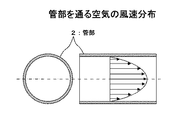
換気システム等で風路を形成する管部では、内周面に近い側では風速が遅く、中央付近では風速が速くなる。 In a pipe part that forms a wind path by a ventilation system or the like, the wind speed is slow near the inner peripheral surface, and the wind speed is fast near the center.
従来の給気グリルでは、イオン発生素子のイオン放出面が管部の内周面と略同一面となるように構成される。このため、イオン発生素子のイオン放出面が、管部中で風速の遅い部分に配設されることになる。 The conventional air supply grill is configured such that the ion emission surface of the ion generating element is substantially flush with the inner peripheral surface of the tube portion. For this reason, the ion emission surface of an ion generating element is arrange | positioned in the part with a slow wind speed in a pipe part.
これにより、従来の給気グリルでは、送風される空気中のイオンの数が少ないという問題があった。 As a result, the conventional air supply grill has a problem that the number of ions in the air to be blown is small.
本発明は、このような課題を解決するためになされたもので、送風される空気中のイオンの量を増やすことができるイオン供給装置を提供することを目的とする。 The present invention has been made to solve such a problem, and an object thereof is to provide an ion supply device capable of increasing the amount of ions in the air to be blown.
上述した課題を解決するため、本発明のイオン供給装置は、イオン発生素子で発生させたイオンが空気流で送風されるイオン供給装置において、イオン発生素子のイオン放出面の前方に、空気の流れに沿った前後面を少なくとも開口させて、空気の流れに沿った前後面に風路形成開口部を有した空間を形成する空間形成部が、イオン放出面に対向して形成される取り付け部材によって、イオン発生素子は、空気流が生成される風路を形成する風路形成部材の内周面から内側に向けて突出させて取り付けられ、風路形成開口部は、前記イオン発生素子側の開口位置が、前記イオン放出面と略同一面となる構成で、イオン発生素子は、イオン放出面が風路形成部材によって生成される空気の流れに沿うように、かつ、イオン放出面の風路形成部材の内周面からの突出高さが、風路形成部材の内周面の高さに対して1/2以下の範囲に配設されるように、取り付け部材によって風路形成部材に固定されることを特徴とする。
In order to solve the above-described problems, an ion supply apparatus according to the present invention is an ion supply apparatus in which ions generated by an ion generation element are blown by an air flow, and an air flow is provided in front of an ion emission surface of the ion generation element. A space forming portion that forms a space having an air passage forming opening on the front and rear surfaces along the air flow at least by opening the front and rear surfaces along the air flow . The ion generating element is attached so as to protrude inward from the inner peripheral surface of the air path forming member that forms the air path in which the air flow is generated, and the air path forming opening is an opening on the ion generating element side. The ion generating element is configured so that the position is substantially flush with the ion emission surface, and the ion emission surface is formed along the flow of air generated by the air channel formation member, and the ion emission surface is formed with an air path. Element The protruding height from the inner peripheral surface is fixed to the air path forming member by the mounting member so that the height of the inner peripheral surface of the air path forming member is ½ or less. It is characterized by.
本発明のイオン供給装置では、イオン発生素子が風路形成部材の内周面から内側に向けて突出し、イオン発生素子のイオン放出面が、風路形成部材の内部で風速の速い部分に配設される。 In the ion supply device of the present invention, the ion generating element protrudes inward from the inner peripheral surface of the air path forming member, and the ion emitting surface of the ion generating element is disposed in the portion of the air path forming member where the wind speed is high. Is done.
これにより、イオン発生素子でイオンを発生させると、送風される空気中のイオンの数が増加する。 Thereby, when ions are generated by the ion generating element, the number of ions in the blown air increases.
本発明のイオン供給装置によれば、イオン発生素子のイオン放出面が、風路形成部材の内部で風速の速い部分に配設されるので、送風される空気中のイオンの数を増加させることができる。 According to the ion supply device of the present invention, since the ion emission surface of the ion generating element is disposed in the portion where the wind speed is high inside the air passage forming member, the number of ions in the air to be blown is increased. Can do.
以下、図面を参照して本発明のイオン供給装置の実施の形態について説明する。 Embodiments of an ion supply device of the present invention will be described below with reference to the drawings.
<給気グリルの構成例>
図1は、イオン供給装置の実施の形態としての給気グリルの一例を示す側断面図、図2は、本実施の形態の給気グリルの一例を示す正面断面図である。
<Configuration example of air supply grille>
FIG. 1 is a side sectional view showing an example of an air supply grill as an embodiment of an ion supply device, and FIG. 2 is a front cross-sectional view showing an example of an air supply grill according to the present embodiment.
また、図3は、本実施の形態の給気グリルの平面図で、図1に示す側断面図は、図3に示すA−A線を切断面とした矢視図、図2に示す正面断面図は、図3に示すB−B線を切断面とした矢視図である。 3 is a plan view of the air supply grill according to the present embodiment, and the side sectional view shown in FIG. 1 is an arrow view taken along the line AA shown in FIG. 3 and a front view shown in FIG. The cross-sectional view is a cross-sectional view taken along the line BB shown in FIG.
更に、図4は、本実施の形態の給気グリルの一例を示す平面断面図、図5は、本実施の形態の給気グリルの一例を示す分解斜視図である。 FIG. 4 is a plan sectional view showing an example of an air supply grill according to the present embodiment, and FIG. 5 is an exploded perspective view showing an example of the air supply grill according to the present embodiment.
本実施の形態の給気グリル1Aは、空気が通る風路を形成する管部2と、管部2を通る空気にイオンを供給するイオン発生器3と、イオンが供給された空気が吹き出されるグリル本体4を備える。
An air supply grill 1A according to the present embodiment includes a
グリル本体4は、空気が通る開口部40と、開口部40と対向して着脱可能に取り付けられる正面パネル41と、開口部4の周縁に形成されたフランジ部42と、正面パネル41の周縁に形成された吹出口43を備える。
The
給気グリル1Aは、グリル本体4のフランジ部42と、グリル本体4に備えられた図示しない取り付け金具との間に、住宅の天井等を構成する板材100を挟み込むことで、吹出口43を室内側に露出させた状態で、住宅の天井等に固定される。
The
イオン発生器3はイオン発生素子の一例で、略同数の正イオンと負イオンがイオン放出面30から放出される。イオン発生器3の原理について説明すると、イオン発生器3は、図示しない一対の電極が誘電体を介して対向配置され、電極間に家庭用交流電源等から取った交流電圧を昇圧して印加することにより、コロナ放電を起こし、空気中の酸素ないしは水分が電離によりエネルギーを受けてイオン化し、H+(H2O)m(mは任意の自然数)と、O2 -(H2O)n(nは任意の自然数)が主体のイオンを放出するものである。
The
これらH+(H2O)m及びO2 -(H2O)nは、浮遊菌の表面に付着し、化学反応して活性種であるH2O2または・OHを生成する。H2O2または・OHは、極めて強力な活性を示すため、これらにより、空気中の浮遊細菌を取り囲んで除去することができる。ここで、・OHは活性種の1種であり、ラジカルのOHを示している。 These H + (H 2 O) m and O 2 − (H 2 O) n adhere to the surface of the floating bacteria and chemically react to generate H 2 O 2 or .OH as an active species. Since H 2 O 2 or .OH exhibits very strong activity, they can surround and remove airborne bacteria. Here, .OH is one kind of active species, and represents radical OH.
これにより、イオン発生器3で略同数の正イオンと負イオンを発生させ、管部2を通る空気に略同数の正イオンと負イオンを供給することで、空気中の浮遊雑菌が除去される。
Thereby, approximately the same number of positive ions and negative ions are generated by the
管部2は風路形成部材の一例で、断面形状が中空の円形で、例えばL字状に曲がった形態を有し、一端側がグリル本体4と接続される。また、管部2は、イオン発生器3が取り付けられる取り付け台座20が形成された開口部21が、本例では上面に形成されている。なお、管部2は、直線状であっても良い。
The
給気グリル1Aは、イオン発生器3が取り付け部材5に取り付けられ、イオン発生器3が取り付けられた取り付け部材5が、管部2の取り付け台座20に取り付けられる。
In the
また、給気グリル1Aは、取り付け部材5を介して管部2に取り付けられる基板ボックス10を備える。基板ボックス10内には、イオン発生器3を駆動する各種素子が実装された基板10aが取り付けられ、イオン発生器3と基板10aが図示しない配線で電気的に接続される。
In addition, the
次に、各図を参照して、イオン発生器3を管部2に取り付ける取り付け部材5の構成について説明する。
Next, with reference to each figure, the structure of the
取り付け部材5は、イオン発生器3が固定される爪部50aとリブ50bを有し、管部2の開口部21に挿入される枠部50と、爪部50aとリブ50bで枠部50に固定されたイオン発生器3のイオン放出面30の前方に所定の高さの空間51aを形成する空間形成部51を備える。
The
また、取り付け部材5は、管部2における空気の流れる方向に沿って空間51aの前面及び後面の枠部50を開口した風路形成開口部52と、イオン発生器3のイオン放出面30と空間51aを挟んで対向する空間形成部51を開口したイオン放出面開口部53を備える。
The
更に、取り付け部材5は、管部2の取り付け台座20に形成されたネジ穴20aの位置に合わせて孔部が形成された取り付け片部54を、枠部50に備える。
Furthermore, the
取り付け部材5の風路形成開口部52は、イオン発生器3側の開口位置が、イオン発生器3のイオン放出面30と略同一面となる構成である。これにより、給気グリル1Aでは、管部2を通る空気の流れに対して上流側の風路形成開口部52から空間51aに取り入れられた空気が、イオン発生器3のイオン放出面30に沿って流れ、空気の流れに対して下流側の風路形成開口部52から吹き出される。
The air
また、取り付け部材5の風路形成開口部52は、イオン発生器3のイオン放出面30から空間形成部51までの高さHを、空間51aに人の指が入らない程度とした構成で、本例では、空間形成部51までの高さが、12mm以下で10mm程度の8mmに設定される。
Further, the air passage forming opening 52 of the
更に、空間形成部51のイオン放出面開口部53は、人の指が入らない程度の大きさの開口が格子状に並べられた構成である。また、イオン放出面開口部53は、管部2における空気の流れに沿って突出した凸部53aを備え、イオン発生器3のイオン放出面30の前方の空間51aにおける整流効果を持たせている。
Furthermore, the ion emission surface opening 53 of the space forming portion 51 has a configuration in which openings having a size that does not allow a human finger to enter are arranged in a lattice pattern. Further, the ion emission surface opening 53 includes a
次に、管部2に取り付けられた状態のイオン発生器3及び取り付け部材5の構成について説明する。
Next, the structure of the
給気グリル1Aは、取り付け部材5の内周面と接するイオン発生器3の外周面に、封止部材としてのパッキン31が貼り付けられ、パッキン31が貼り付けられたイオン発生器3が枠部50に挿入されることで、イオン発生器3が爪部50aとリブ50bで取り付け部材5に固定される。
In the supply air grill 1A, a packing 31 as a sealing member is attached to the outer peripheral surface of the
給気グリル1Aは、イオン発生器3が取り付け部材5に取り付けられると、イオン発生器3と取り付け部材5との間に入るパッキン31によって、イオン発生器3と取り付け部材5との取り付け部位での気密が保たれる。
When the
また、給気グリル1Aは、管部2の開口部21の内周面と接する取り付け部材5の外周面に、封止部材としてのパッキン55が貼り付けられ、イオン発生器3が取り付けられると共に、パッキン55が貼り付けられた取り付け部材5が、管部2の開口部21に挿入される。
In addition, the air supply grill 1A has a packing 55 as a sealing member attached to the outer peripheral surface of the
給気グリル1Aは、管部2の開口部21に挿入された取り付け部材5の取り付け片部54が、管部2の取り付け台座20に載せられ、ネジ6が締結されることで、イオン発生器3が取り付け部材5により管部2に取り付けられる。
In the air supply grille 1A, the
給気グリル1Aは、取り付け部材5が管部2に取り付けられると、取り付け部材5と管部2との間に入るパッキン55によって、取り付け部材5と管部2との取り付け部位での気密が保たれる。
When the
これにより、給気グリル1Aは、管部2を通る空気が、イオン発生器3と取り付け部材5との取り付け部位、及び取り付け部材5と管部2との取り付け部位から漏れることが防止される。
Thereby, the
また、給気グリル1Aは、イオン発生器3が取り付け部材5により管部2に取り付けられると、イオン発生器3のイオン放出面30が、管部2の内周面から所定の高さで突出した位置となり、断面形状が円形の管部2の中心O付近に近づけられる。
Further, in the supply air grill 1A, when the
更に、給気グリル1Aは、取り付け部材5の風路形成開口部52の全面が管部2の内部に露出し、イオン発生器3のイオン放出面30に対向して空間形成部51が設けられることにより、イオン放出面30の前方に形成される空間51aが、管部2による風路中に配設される。
Further, in the air supply grill 1A, the entire surface of the air
図6は、管部を通る空気の風速分布を示す説明図で、風速を矢印の長さで示す。断面形状が円形の管部2の内部を通る空気は、管部2の内周面に近い側では風速が遅く、中心に向かって風速が徐々に速くなり、管部2の中心付近で最も風速が速くなる。
FIG. 6 is an explanatory diagram showing the wind speed distribution of the air passing through the pipe portion, and the wind speed is indicated by the length of the arrow. The air passing through the inside of the
これにより、給気グリル1Aは、取り付け部材5によって管部2の内周面から突出させてイオン発生器3が取り付けられ、イオン発生器3のイオン放出面30が、管部2の中心付近に近づけられることで、正イオンと負イオンを放出するイオン放出面30が、管部2の内部において風速の速い位置に配設される。
As a result, the
給気グリル1Aは、イオン発生器3のイオン放出面30が、管部2の内部で風速の速い位置に配設されると、吹き出される空気中のイオンの数が増加する。
In the supply grill 1A, when the
但し、管部2内にイオン発生器3が突出しているので、イオン発生器3で空気の流れが妨げられて風量が減少し、イオン放出面30の高さが管部2の中心を越えると、風量の減少率が大きくなる。
However, since the
このため、給気グリル1Aから吹き出される空気中のイオンの数と、給気グリル1Aから吹き出される空気の風量を考慮して、イオン発生器3のイオン放出面30の高さが決められ、本例では、管部2の直径に対して約1/6〜1/2の間に、イオン放出面30が配設されるように、イオン発生器3の突出量が設定されている。
For this reason, the height of the
本実施の形態の給気グリル1Aでは、イオン発生器のイオン放出面を、管部の内周面と略同一とした構成と比較して、吹き出される空気中の正イオンと負イオンの数が、約1.5倍程度となった。 In the supply air grill 1A of the present embodiment, the number of positive ions and negative ions in the blown air is compared with a configuration in which the ion emission surface of the ion generator is substantially the same as the inner peripheral surface of the tube portion. However, it became about 1.5 times.
<給気グリルの動作例>
次に、各図を参照して、本実施の形態の給気グリル1Aの動作について説明する。給気グリル1Aは、イオン発生器3のイオン放出面30の前方に形成された空間51aに、管部2を通る空気の流れに対して上流側の風路形成開口部52から空気が取り込まれることで、管部2を通る空気が、イオン発生器3のイオン放出面30に沿って流れる。
<Operation example of air supply grill>
Next, with reference to each figure, operation | movement of 1 A of supply grills of this Embodiment is demonstrated. In the
給気グリル1Aでは、イオン発生器3が駆動され、イオン放出面30から略同数の正イオンと負イオンが放出されると、イオン発生器3のイオン放出面30に沿って流れる空気に、略同数の正イオンと負イオンが供給される。
In the air supply grille 1A, when the
正イオンと負イオンが供給された空気は、管部2を通る空気の流れに対して下流側の風路形成開口部52及びイオン放出面30と対向したイオン放出面開口部53から、管部2を通る空気の流れによって吹き出され、略同数の正イオンと負イオンを含む空気が、グリル本体4の吹出口43から吹き出される。
The air to which positive ions and negative ions are supplied flows from the air flow
給気グリル1Aは、取り付け部材5によって管部2の内周面から突出させてイオン発生器3が取り付けられ、正イオンと負イオンを放出するイオン放出面30が、管部2の内部において風速の速い位置に配設されているので、グリル本体4の吹出口43から吹き出される空気中の正イオンと負イオンの数が増加する。
The air supply grille 1A is protruded from the inner peripheral surface of the
また、給気グリル1Aは、イオン発生器3のイオン放出面30に対向して、管部2における空気の流れる方向に沿った前後面に風路形成開口部52が形成された空間形成部51が設けられることにより、イオン放出面30の前方に空気が通る所定の高さの空間51aが形成される。
Further, the
これにより、管部2を通る空気に対するイオンの供給を阻害しないようにすると共に、空間形成部51によってイオン発生器3のイオン放出面が保護される。
Thereby, while preventing supply of the ion with respect to the air which passes the
上述したように、イオン発生器3のイオン放出面30に沿った空気の流れを発生させるため、空気の流れに沿った空間51aの前後面に風路形成開口部52が形成されると共に、空間形成部51にイオン放出面開口部53が形成される。
As described above, in order to generate an air flow along the
そして、風路形成開口部52及びイオン放出面開口部53の開口部分は、人の指が入らないような大きさに設定されており、管部2内に工具や手が入れられても、イオン発生器3のイオン放出面30に触れられないようにして、イオン放出面30の汚れの付着や損傷を防ぐと共に、安全性が確保される。
And the opening part of the air-path
<換気システムの構成例>
図7は、イオン供給装置としての給気グリルが適用された換気システムの一例を示す構成図、図8は、本実施の形態の換気システムを構成する換気装置の一例を示す構成図で、次に、本実施の形態の給気グリル1Aを備えた換気システム11について説明する。
<Configuration example of ventilation system>
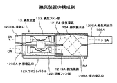
FIG. 7 is a configuration diagram illustrating an example of a ventilation system to which an air supply grill as an ion supply device is applied, and FIG. 8 is a configuration diagram illustrating an example of a ventilation device that configures the ventilation system of the present embodiment. Next, the ventilation system 11 provided with the air supply grille 1A of the present embodiment will be described.
本実施の形態の換気システム11は、外気OAを吸い込んで給気SAとして室内に吹き出すと共に、室内からの還気RAを吸い込んで排気EAとして室外に排出し、かつ、外気OAと室内からの還気RAとの間で熱交換を行う熱交換型の換気装置12を備え、換気装置12に上述した給気グリル1Aが接続される。 The ventilation system 11 according to the present embodiment sucks the outside air OA and blows it out into the room as the supply air SA, sucks the return air RA from the room and discharges it as the exhaust air EA, and returns the outside air OA and the room from the inside. A heat exchange type ventilator 12 that exchanges heat with the air RA is provided, and the above-described air supply grill 1A is connected to the ventilator 12.
換気装置12は、図8に示すように、外気OAが吸い込まれる外部吸込口120OAと、室内への給気SAが吹き出される給気吹出口120SAと、室内からの還気RAが吸い込まれる室内吸込口120RAと、屋外への排気EAが排気される排気口120EAを備える。 As shown in FIG. 8, the ventilator 12 includes an external inlet 120OA through which the outside air OA is sucked in, an air supply outlet 120SA through which the air supply SA into the room is blown out, and a room through which the return air RA from the room is sucked in. A suction port 120RA and an exhaust port 120EA through which exhaust EA to the outside is exhausted are provided.
換気装置12は、外部吸込口120OAから給気吹出口120SAへつながる給気風路121SAが形成され、外部吸込口120OAから外気OAを吸い込み、給気吹出口120SAから給気SAを吹き出す送風ファン部122を備える。 The ventilation device 12 has a supply air passage 121SA connected from the external suction port 120OA to the supply air outlet 120SA, sucks outside air OA from the external suction port 120OA, and blows out the supply air SA from the supply air outlet 120SA. Is provided.
また、換気装置12は、室内吸込口120RAから排気口120EAへつながる排気風路121EAが形成され、室内吸込口120RAから還気RAを吸い込み、排気口120EAから排気EAを排気する換気ファン部123を備える。 The ventilator 12 has an exhaust air passage 121EA connected from the indoor suction port 120RA to the exhaust port 120EA, and has a ventilation fan unit 123 that sucks the return air RA from the indoor suction port 120RA and exhausts the exhaust air EA from the exhaust port 120EA. Prepare.
更に、外部吸込口120OAから吸い込まれた外気OAと室内吸込口120RAから吸い込まれた還気RAとの間で熱交換を行う熱交換素子124を備える。 Furthermore, a heat exchange element 124 that performs heat exchange between the outside air OA sucked from the external suction port 120OA and the return air RA sucked from the indoor suction port 120RA is provided.
熱交換素子124は、給気風路121SAを形成する素材と排気風路121EAを形成する素材が、給気風路121SAと排気風路121EAを直交する向きとして積層される。熱交換素子124は、給気風路121SAと排気風路121EAが、熱伝導性を有すると共に空気を通さない隔壁で仕切られ、給気風路121SAを通る空気と排気風路121EAを通る空気との間で熱交換される。 In the heat exchange element 124, the material forming the supply air passage 121SA and the material forming the exhaust air passage 121EA are stacked so that the supply air passage 121SA and the exhaust air passage 121EA are orthogonal to each other. In the heat exchange element 124, the supply air passage 121SA and the exhaust air passage 121EA are partitioned by a partition wall that has thermal conductivity and does not allow air to pass between the air passing through the supply air passage 121SA and the air passing through the exhaust air passage 121EA. The heat is exchanged at
換気装置12は、給気吹出口120SAにダクト70SAを介して図1等で説明した給気グリル1Aが接続される。また、換気装置12は、下面にフロントパネル125が取り付けられ、室内吸込口120RAがフロントパネル125に露出する。
In the ventilator 12, the air supply grill 1A described in FIG. 1 and the like is connected to the air supply outlet 120SA via a duct 70SA. Further, the ventilator 12 has a
尚、換気装置12は、給気風路121SAと排気風路121EAに図示しないフィルタを備え、熱交換素子124に埃等が付着しないように構成される。 The ventilation device 12 includes a filter (not shown) in the supply air passage 121SA and the exhaust air passage 121EA so that dust or the like does not adhere to the heat exchange element 124.
換気システム11が設置される建物71は、図7に示すように、本例では一戸建て住宅を例にしており、居間や台所等、壁や扉72aで仕切られた複数の部屋72を有する。建物71は、例えば廊下73の天井裏に換気装置12が設置され、換気装置12と各部屋72の天井に設置された給気グリル1Aが、ダクト70SAで接続される。
As shown in FIG. 7, the building 71 in which the ventilation system 11 is installed is a single-family house in this example, and has a plurality of
建物71は、外壁に屋外フード74OAと屋外フード74EAを備え、換気システム11は、図8に示す換気装置12の外部吸込口120OAが、ダクト70OAを介して屋外フード74OAと接続される。また、排気口120EAが、ダクト70EAを介して屋外フード74EAと接続される。 The building 71 includes an outdoor hood 74OA and an outdoor hood 74EA on the outer wall, and the ventilation system 11 has an external suction port 120OA of the ventilation device 12 shown in FIG. 8 connected to the outdoor hood 74OA via a duct 70OA. Further, the exhaust port 120EA is connected to the outdoor hood 74EA through the duct 70EA.
また、換気装置12は、室内吸込口120RAが形成されたフロントパネル125が、廊下73の天井に露出する。
Further, in the ventilation device 12, the
なお、建物71は、扉72aに設けたアンダーカットUや、図示しないガラリ等の開口部を通して部屋72と廊下73との間等で空気が流れる構成である。これにより、各部屋72の給気グリル1Aから給気SAが吹き出されると共に、各部屋72の空気が、アンダーカットUやガラリを通り廊下73の換気装置12から吸い込まれる空気の流れが形成される。
The building 71 has a configuration in which air flows between the
<換気システムの動作例>
次に、各図を参照して本実施の形態の換気システム11の動作の一例について説明する。
<Operation example of ventilation system>
Next, an example of operation | movement of the ventilation system 11 of this Embodiment is demonstrated with reference to each figure.
換気システム11は、給排気が機械換気で行われる第1種換気システムを構成し、所定時間で各部屋72の空気が入れ替えられる換気風量で、24時間連続運転される。すなわち、換気装置12では、送風ファン部122と換気ファン部123が、所定の換気風量が得られる回転数で駆動される。
The ventilation system 11 constitutes a first type ventilation system in which air supply and exhaust are performed by mechanical ventilation, and is continuously operated for 24 hours with a ventilation air volume in which the air in each
換気装置12は、送風ファン部122が駆動されると、給気風路121SAを外部吸込口120OAから給気吹出口120SAへ向かう空気の流れが発生する。また、換気装置12は、換気ファン部123が駆動されると、排気風路121EAを室内吸込口120RAから排気口120EAへ向かう空気の流れが発生する。 When the blower fan 122 is driven, the ventilation device 12 generates an air flow through the supply air passage 121SA from the external suction port 120OA to the supply air outlet 120SA. Further, in the ventilator 12, when the ventilation fan unit 123 is driven, an air flow is generated in the exhaust air passage 121EA from the indoor suction port 120RA to the exhaust port 120EA.
これにより、換気装置12では、建物外壁の屋外フード74OAからダクト70OAを通り外部吸込口120OAへ外気OAが吸い込まれ、熱交換素子124を通って給気吹出口120SAから給気SAが吹き出される。 Thereby, in the ventilator 12, the outside air OA is sucked from the outdoor hood 74OA on the outer wall of the building through the duct 70OA to the external suction port 120OA, and the supply air SA is blown out from the supply air outlet 120SA through the heat exchange element 124. .
また、アンダーカットUや図示しないガラリを通して、廊下73のフロントパネル125から室内吸込口120RAへ各部屋72からの還気RAが吸い込まれ、熱交換素子124を通って排気口120EAから排気EAが排出され、排気口120EAから排出された排気EAは、ダクト70EAを通り建物外壁の屋外フード74EAから屋外へ排出される。
Further, the return air RA from each
そして、外部吸込口120OAから吸い込まれた外気OAと室内吸込口120RAから吸い込まれた還気RAが、熱交換素子124を通ることで熱交換されて、室温に近づけられた給気SAが給気吹出口120SAから吹き出される。 Then, the outside air OA sucked from the external suction port 120OA and the return air RA sucked from the indoor suction port 120RA are heat-exchanged by passing through the heat exchange element 124, and the supply air SA brought close to room temperature is supplied. It blows out from the blower outlet 120SA.
換気装置12の給気吹出口120SAから吹き出された給気SAは、ダクト70SAを通り給気グリル1Aから吹き出される。 The supply air SA blown from the supply air outlet 120SA of the ventilation device 12 passes through the duct 70SA and is blown out of the supply air grill 1A.
給気グリル1Aは、上述したように、図1等に示すイオン発生器3が駆動されると、イオン発生器3から略同数の正イオンと負イオンが放出され、管部2を通る空気に略同数の正イオンと負イオンが供給される。
As described above, when the
これにより、換気装置12から給気グリル1Aに供給された給気SAに、略同数の正イオンと負イオンが供給され、略同数の正イオンと負イオンを含む空気が、給気SAとして給気グリル1Aの吹出口43から吹き出される。 Thereby, substantially the same number of positive ions and negative ions are supplied to the supply air SA supplied from the ventilator 12 to the supply air grill 1A, and air containing approximately the same number of positive ions and negative ions is supplied as the supply air SA. It blows out from the blower outlet 43 of the air grill 1A.
図7に示すような建物71において、給気グリル1Aが備えられた部屋に略同数の正イオンと負イオンを含む空気が供給されることで、空気中の浮遊雑菌が除去される。
In a building 71 as shown in FIG. 7, air containing approximately the same number of positive ions and negative ions is supplied to a room provided with the
本発明は、換気装置等にダクトを介して接続され、換気装置から送風された空気を吹き出す給気グリル、換気装置への空気が吸い込まれる吸込グリル等の換気グリル、給気ファンを備えた給気装置、換気装置による換気によって空気が吸い込まれる室内に給気する自然給気口等に適用される。 The present invention is connected to a ventilator or the like through a duct and is provided with an air supply grill that blows out air blown from the ventilator, a suction grill that sucks air into the ventilator, and an air supply fan. It is applied to a natural air supply port that supplies air into a room where air is sucked in by a ventilation device or a ventilation device.
1A・・・給気グリル、2・・・管部、20・・・取り付け台座、21・・・開口部、3・・・イオン発生器、30・・・イオン放出面、4・・・グリル本体、5・・・取り付け部材、50・・・枠部、51・・・空間形成部、51a・・・空間、52・・・風路形成開口部、53・・・イオン放出面開口部 DESCRIPTION OF SYMBOLS 1A ... Supply air grill, 2 ... Pipe part, 20 ... Mounting base, 21 ... Opening part, 3 ... Ion generator, 30 ... Ion discharge surface, 4 ... Grill Main body, 5 ... Mounting member, 50 ... Frame, 51 ... Space forming part, 51a ... Space, 52 ... Air channel forming opening, 53 ... Ion emission surface opening
Claims (2)
前記イオン発生素子の前記イオン放出面の前方に、空気の流れに沿った前後面を少なくとも開口させて、空気の流れに沿った前後面に風路形成開口部を有した空間を形成する空間形成部が、前記イオン放出面に対向して取り付け部材によって形成され、前記取り付け部材によって、前記イオン発生素子は、空気流が生成される風路を形成する風路形成部材の内周面から内側に向けて突出させて取り付けられ、
前記風路形成開口部は、前記イオン発生素子側の開口位置が、前記イオン放出面と略同一面となる構成で、
前記イオン発生素子は、前記イオン放出面が前記風路形成部材によって生成される空気の流れに沿うように、
かつ、前記イオン放出面の前記風路形成部材の内周面からの突出高さが、前記風路形成部材の内周面の高さに対して1/6〜1/2の範囲に配設されるように、前記取り付け部材によって前記風路形成部材に固定される
ことを特徴とするイオン供給装置。 In the ion supply device in which ions generated by the ion generating element are blown by an air flow,
A space is formed in front of the ion emission surface of the ion generating element by opening at least front and rear surfaces along the air flow to form a space having an air passage forming opening on the front and rear surfaces along the air flow. A portion is formed by an attachment member so as to face the ion emission surface, and by the attachment member, the ion generation element is formed on the inner side from the inner peripheral surface of the air passage forming member that forms an air passage in which an air flow is generated. It is attached to protrude
The air path forming opening is configured such that the opening position on the ion generating element side is substantially flush with the ion emission surface.
The ion generating element is arranged so that the ion emission surface follows a flow of air generated by the air passage forming member.
And the protrusion height from the internal peripheral surface of the said air path formation member of the said ion discharge | release surface is arrange | positioned in the range of 1/6-1/2 with respect to the height of the internal peripheral surface of the said air path formation member. As described above, the ion supply device is fixed to the air passage forming member by the attachment member.
前記イオン発生素子が取り付けられる前記取り付け部材が取り付けられる台座が、前記風路形成部材の屈曲した方向に対して外側に設けられる
ことを特徴とする請求項1記載のイオン供給装置。 The air passage forming member has a bent form,
The ion supply device according to claim 1, wherein a pedestal to which the attachment member to which the ion generating element is attached is attached is provided on an outer side with respect to a bent direction of the air passage forming member.
Priority Applications (1)
| Application Number | Priority Date | Filing Date | Title |
|---|---|---|---|
| JP2007299671A JP5378675B2 (en) | 2007-11-19 | 2007-11-19 | Ion supply device |
Applications Claiming Priority (1)
| Application Number | Priority Date | Filing Date | Title |
|---|---|---|---|
| JP2007299671A JP5378675B2 (en) | 2007-11-19 | 2007-11-19 | Ion supply device |
Publications (2)
| Publication Number | Publication Date |
|---|---|
| JP2009127871A JP2009127871A (en) | 2009-06-11 |
| JP5378675B2 true JP5378675B2 (en) | 2013-12-25 |
Family
ID=40818996
Family Applications (1)
| Application Number | Title | Priority Date | Filing Date |
|---|---|---|---|
| JP2007299671A Active JP5378675B2 (en) | 2007-11-19 | 2007-11-19 | Ion supply device |
Country Status (1)
| Country | Link |
|---|---|
| JP (1) | JP5378675B2 (en) |
Families Citing this family (2)
| Publication number | Priority date | Publication date | Assignee | Title |
|---|---|---|---|---|
| JP4528871B1 (en) * | 2009-07-13 | 2010-08-25 | シャープ株式会社 | Ion delivery device |
| WO2011007597A1 (en) * | 2009-07-13 | 2011-01-20 | シャープ株式会社 | Ion-delivery device |
Family Cites Families (3)
| Publication number | Priority date | Publication date | Assignee | Title |
|---|---|---|---|---|
| JP2003074888A (en) * | 2001-08-28 | 2003-03-12 | Toshiba Kyaria Kk | Indoor unit of air conditioner |
| JP4163540B2 (en) * | 2003-03-24 | 2008-10-08 | マックス株式会社 | Ventilator and building using the same |
| JP4073824B2 (en) * | 2003-05-29 | 2008-04-09 | マックス株式会社 | Blower |
-
2007
- 2007-11-19 JP JP2007299671A patent/JP5378675B2/en active Active
Also Published As
| Publication number | Publication date |
|---|---|
| JP2009127871A (en) | 2009-06-11 |
Similar Documents
| Publication | Publication Date | Title |
|---|---|---|
| JP4734966B2 (en) | Air purifier | |
| JP4830340B2 (en) | Heat exchange ventilator | |
| JP5378675B2 (en) | Ion supply device | |
| JP5301798B2 (en) | Air conditioner | |
| JP5305640B2 (en) | Ion supply device | |
| JP5099095B2 (en) | Blower | |
| JP4073824B2 (en) | Blower | |
| JP4900053B2 (en) | Ventilation equipment | |
| JP5010432B2 (en) | Ion generator and ventilation system | |
| JP2012123996A (en) | Ion generator | |
| JP5209753B2 (en) | Ventilation system | |
| JP2015075282A (en) | Ion delivery device | |
| JP5640891B2 (en) | Blower | |
| JP2017009259A (en) | Ventilation device and ventilation system | |
| JP2008116202A (en) | Installation structure of ion generating element, air blowing structure using the installation structure, air conditioner and air-conditioning system | |
| JP2008089301A (en) | Air supply port structure, ventilation system, and building using the same | |
| JP4690111B2 (en) | Ventilation equipment | |
| JP5388982B2 (en) | Air purifier and building | |
| JP2016169879A (en) | Ventilation device | |
| WO2014115297A1 (en) | Ventilation device | |
| JP2015183982A (en) | Ventilation device | |
| JP2003065557A (en) | Air conditioner | |
| JP2014020578A (en) | Air conditioner | |
| JP2011099638A (en) | Piping connection member, blowing system, and building | |
| JP4960735B2 (en) | Air supply grill for residential ventilation systems |
Legal Events
| Date | Code | Title | Description |
|---|---|---|---|
| A621 | Written request for application examination |
Free format text: JAPANESE INTERMEDIATE CODE: A621 Effective date: 20100806 |
|
| RD02 | Notification of acceptance of power of attorney |
Free format text: JAPANESE INTERMEDIATE CODE: A7422 Effective date: 20110906 |
|
| A977 | Report on retrieval |
Free format text: JAPANESE INTERMEDIATE CODE: A971007 Effective date: 20111117 |
|
| A131 | Notification of reasons for refusal |
Free format text: JAPANESE INTERMEDIATE CODE: A131 Effective date: 20111129 |
|
| A521 | Written amendment |
Free format text: JAPANESE INTERMEDIATE CODE: A523 Effective date: 20120130 |
|
| A02 | Decision of refusal |
Free format text: JAPANESE INTERMEDIATE CODE: A02 Effective date: 20120724 |
|
| A521 | Written amendment |
Free format text: JAPANESE INTERMEDIATE CODE: A523 Effective date: 20121024 |
|
| A911 | Transfer to examiner for re-examination before appeal (zenchi) |
Free format text: JAPANESE INTERMEDIATE CODE: A911 Effective date: 20121031 |
|
| A912 | Re-examination (zenchi) completed and case transferred to appeal board |
Free format text: JAPANESE INTERMEDIATE CODE: A912 Effective date: 20121207 |
|
| A521 | Written amendment |
Free format text: JAPANESE INTERMEDIATE CODE: A523 Effective date: 20130805 |
|
| A61 | First payment of annual fees (during grant procedure) |
Free format text: JAPANESE INTERMEDIATE CODE: A61 Effective date: 20130926 |
|
| R150 | Certificate of patent or registration of utility model |
Ref document number: 5378675 Country of ref document: JP Free format text: JAPANESE INTERMEDIATE CODE: R150 Free format text: JAPANESE INTERMEDIATE CODE: R150 |