JP5378172B2 - Optical waveguide core manufacturing method, optical waveguide manufacturing method, optical waveguide, and photoelectric composite wiring board - Google Patents
Optical waveguide core manufacturing method, optical waveguide manufacturing method, optical waveguide, and photoelectric composite wiring board Download PDFInfo
- Publication number
- JP5378172B2 JP5378172B2 JP2009267504A JP2009267504A JP5378172B2 JP 5378172 B2 JP5378172 B2 JP 5378172B2 JP 2009267504 A JP2009267504 A JP 2009267504A JP 2009267504 A JP2009267504 A JP 2009267504A JP 5378172 B2 JP5378172 B2 JP 5378172B2
- Authority
- JP
- Japan
- Prior art keywords
- core
- optical waveguide
- metal layer
- forming
- layer
- Prior art date
- Legal status (The legal status is an assumption and is not a legal conclusion. Google has not performed a legal analysis and makes no representation as to the accuracy of the status listed.)
- Active
Links
Images


Abstract
Description
本発明は、光導波路コアの製造方法、光導波路の製造方法、前記光導波路の製造方法により製造された光導波路、及び前記光導波路を備える光電気複合配線板に関するものである。 The present invention relates to an optical waveguide core manufacturing method, an optical waveguide manufacturing method, an optical waveguide manufactured by the optical waveguide manufacturing method, and an optoelectric composite wiring board including the optical waveguide.
昨今の各種情報処理機器内における信号高速化に付随する高周波ノイズや、伝送帯域不足の問題を解決するものとして、光を内部に導波させる光導波路を内蔵したプリント基板である光電気複合配線板が注目されている。 An opto-electric composite wiring board, which is a printed circuit board with a built-in optical waveguide that guides light inside, as a solution to high-frequency noise accompanying the speed-up of signals in various information processing devices and the shortage of transmission bandwidth. Is attracting attention.
このような光電気複合配線板においては、光を所望の角度に曲げて、例えば、光導波路から光を入出力すること等を目的として、光導波路のコア部に、光を反射可能な傾斜面が形成されている。このような傾斜面が形成された光導波路を製造する方法としては、例えば、非特許文献1や特許文献1に記載の方法等が挙げられる。
In such an opto-electric composite wiring board, an inclined surface capable of reflecting light on the core portion of the optical waveguide for the purpose of bending light to a desired angle, for example, to input / output light from the optical waveguide Is formed. Examples of a method for manufacturing an optical waveguide having such an inclined surface include the methods described in Non-Patent
非特許文献1には、光導波路を製造する方法として、以下のような製造方法が記載されている。まず、仮基板上に形成された第1クラッド層の表面に、感光性材料層を形成し、その感光性材料層を選択露光することによって、光導波路のコア部を形成する。そして、そのコア部を回転刃等により加工することにより、前記コアに、光を反射させるための傾斜面を形成し、前記傾斜面の反射効率を向上させるために、前記傾斜面上に金属層を形成する。その後、金属層が形成されたコア部を埋設するように第2クラッド層を形成する。そうすることによって、仮基板上に光導波路が形成される。そして、最後に、形成された光導波路の第2クラッド層に、本来、光導波路を形成しようとしていた基板を貼り付けるとともに、前記仮基板を剥離させる。
Non-Patent
特許文献1には、下部クラッド層の上にこれより屈折率の大きいコア部をパターニングにより形成する第1工程と、基体の全面を前記コア部及び前記下部クラッド層の双方に対してエッチング速度又は現像液熔解製の異なる光路屈曲手段形成用の材料層で被覆する第2工程と、前記材料層をパターニングすることにより、前記コア部の端面に対して所定の角度をもって対向される端面(傾斜面)を光反射面とする光路屈曲手段を形成する第3工程と、基体の全面を上部クラッド層で被覆することにより埋込型の光導波路を形成する第4工程とを有する光信号伝送システムの製造方法が記載されている。
In
傾斜面が形成された光導波路を製造する方法としては、コア部に傾斜面を形成できるだけではなく、製造効率が高く、そして、その傾斜面に金属層が選択的に形成できること等も求められている。 As a method of manufacturing an optical waveguide having an inclined surface, not only can the inclined surface be formed in the core part, but also the manufacturing efficiency is high and a metal layer can be selectively formed on the inclined surface. Yes.
非特許文献1によれば、傾斜面を有する光導波路を形成できる旨が開示されている。そして、その傾斜面の表面には、光の反射効率を高めるための金属層が形成されることが開示されている。
Non-patent
しかしながら、上述したように、光導波路を仮基板上に形成するので、光導波路が形成された後に、仮基板から剥離して、本来、光導波路を形成しようとしていた基板に貼りなおさなければならないという問題があった。そして、仮基板から剥離する必要があるので、仮基板と第1クラッド層との剥離性を考慮した、仮基板や第1クラッド層の材料選択をしなければならないという問題もあった。 However, as described above, since the optical waveguide is formed on the temporary substrate, after the optical waveguide is formed, it must be peeled off from the temporary substrate and reattached to the substrate on which the optical waveguide was originally formed. There was a problem. And since it is necessary to peel from a temporary substrate, there also existed a problem that the material of a temporary substrate and a 1st cladding layer had to be selected in consideration of the peelability of a temporary substrate and a 1st cladding layer.
また、特許文献1によれば、光反射面として、コア部の端面に対して所定の角度をもって対向される傾斜面を精度良く製造することができる旨が開示されている。そして、前記傾斜面に、金属薄膜を被着させてもよい旨が開示されている。
Further, according to
しかしながら、前記金属薄膜の被着方法については、特に検討されておらず、一般的な方法で被着させると、前記傾斜面だけではなく、コア部の端面等にも付着されるという問題があった。 However, the method for depositing the metal thin film has not been particularly studied, and if deposited by a general method, there is a problem that it adheres not only to the inclined surface but also to the end surface of the core portion. It was.
本発明は、かかる事情に鑑みてなされたものであって、所定の角度をなす傾斜面を有する光導波路コアを効率的に製造することができ、前記傾斜面に選択的に金属膜を形成させることができる光導波路コアの製造方法を提供することを目的とする。また、前記傾斜面を有する光導波路コアを備える光導波路の製造方法、前記光導波路の製造方法により製造された光導波路、及び前記光導波路を備える光電気複合配線板を提供することを目的とする。 The present invention has been made in view of such circumstances, and can efficiently manufacture an optical waveguide core having an inclined surface having a predetermined angle, and a metal film is selectively formed on the inclined surface. An object of the present invention is to provide a method for manufacturing an optical waveguide core. Another object of the present invention is to provide an optical waveguide manufacturing method including the optical waveguide core having the inclined surface, an optical waveguide manufactured by the optical waveguide manufacturing method, and an optoelectric composite wiring board including the optical waveguide. .
本発明の一態様に係る光導波路コアの製造方法は、基板上に形成されたクラッド層の表面に、コア部を形成するコア部形成工程と、前記コア部に、前記クラッド層に対して略垂直な垂直面と、前記垂直面に対向し、前記クラッド層の反対側から入射される光を前記コア部内に誘導又は前記コア部から出射される光を前記クラッド層の反対側に導出するように、光を反射させるための傾斜面とを有する凹部を形成する凹部形成工程と、前記凹部に金属層を形成する金属層形成工程と、前記垂直面に形成された金属層を選択的に除去することによって、少なくとも前記傾斜面上に金属層を残存させる金属層除去工程とを備えることを特徴とする。 An optical waveguide core manufacturing method according to an aspect of the present invention includes: a core part forming step of forming a core part on a surface of a cladding layer formed on a substrate; and the core part substantially with respect to the cladding layer. A vertical vertical plane and the vertical plane facing the vertical plane, and guides light incident from the opposite side of the cladding layer into the core portion or guides light emitted from the core portion to the opposite side of the cladding layer. Forming a recess having an inclined surface for reflecting light, forming a metal layer in the recess, and selectively removing the metal layer formed on the vertical surface. And a metal layer removing step of leaving the metal layer on at least the inclined surface.
このような構成によれば、光導波路コアを製造する際、クラッド層の表面に、コア部を形成し、形成されたコア部に傾斜面を有する凹部を形成する。そして、コア部に形成された凹部に金属層を形成し、傾斜面に対向する垂直面に形成された金属層を選択的に除去することによって、所定の角度をなす傾斜面に選択的に金属膜が形成された光導波路コアを効率的に製造することができる。 According to such a structure, when manufacturing an optical waveguide core, a core part is formed in the surface of a clad layer, and the recessed part which has an inclined surface in the formed core part is formed. Then, a metal layer is formed in the concave portion formed in the core portion, and the metal layer formed on the vertical surface facing the inclined surface is selectively removed, thereby selectively removing the metal on the inclined surface having a predetermined angle. An optical waveguide core on which a film is formed can be efficiently manufactured.
また、前記傾斜面のみに金属層を均一に形成させることは困難である。このことは、特に前記凹部が小さい場合に顕著である。本製造方法によれば、前記凹部が小さい場合であっても、前記垂直面上の金属層を選択的に除去するので、好適な金属層が形成できる。 In addition, it is difficult to form a metal layer uniformly only on the inclined surface. This is particularly noticeable when the concave portion is small. According to this manufacturing method, even when the concave portion is small, the metal layer on the vertical surface is selectively removed, so that a suitable metal layer can be formed.
以上より、所定の角度をなす傾斜面を有する光導波路コアを効率的に製造することができ、前記傾斜面に選択的に金属膜を形成させることができる。 As described above, an optical waveguide core having an inclined surface having a predetermined angle can be efficiently manufactured, and a metal film can be selectively formed on the inclined surface.
さらに、製造された光導波路コアを埋設するように、別途クラッド層を形成することにより、光導波路を形成することができる。その際、前記光導波路コアに入射される光や前記光導波路コアから出射された光が、前記基板を通過しないので、前記基板として、どのような基板であっても用いることができ、例えば、光導波路を形成しようとする基板をそのまま用いることができる。よって、仮基板を用い、その仮基板を剥離するという工程が不要になり、光導波路を効率的に製造することができる。 Furthermore, an optical waveguide can be formed by forming a separate cladding layer so as to embed the manufactured optical waveguide core. At that time, since the light incident on the optical waveguide core and the light emitted from the optical waveguide core do not pass through the substrate, any substrate can be used as the substrate. The substrate on which the optical waveguide is to be formed can be used as it is. Therefore, the step of using the temporary substrate and peeling the temporary substrate is not necessary, and the optical waveguide can be efficiently manufactured.
また、前記金属層除去工程が、前記垂直面上の金属層を、その外表面を基準として前記金属層の厚み分以上除去することによって、前記傾斜面上の金属層を残存させる工程であることが好ましい。 Further, the metal layer removing step is a step of leaving the metal layer on the inclined surface by removing the metal layer on the vertical surface by the thickness of the metal layer or more on the basis of the outer surface thereof. Is preferred.
このような構成によれば、前記垂直面上に形成される金属層が容易に除去され、前記傾斜面上に金属層を容易に残存させることができる。よって、前記傾斜面に選択的に金属膜を容易に形成させることができる。 According to such a configuration, the metal layer formed on the vertical surface can be easily removed, and the metal layer can easily remain on the inclined surface. Therefore, a metal film can be easily selectively formed on the inclined surface.
また、前記コア部形成工程が、基板上に形成されたクラッド層の表面に、感光性材料からなるコア材料層を形成するコア材料層形成工程と、前記コア材料層を選択露光し、さらに現像することによって、所定の形状のコア部を形成するコア部形成工程とを備えることが好ましい。 The core part forming step includes a core material layer forming step of forming a core material layer made of a photosensitive material on the surface of the clad layer formed on the substrate; the core material layer is selectively exposed; and further development is performed. It is preferable to include a core part forming step of forming a core part having a predetermined shape.
このような構成によれば、コア部を容易に形成でき、よって、所定の角度をなす傾斜面に選択的に金属膜が形成された光導波路コアをより効率的に製造することができる。 According to such a configuration, the core portion can be easily formed, and thus the optical waveguide core in which the metal film is selectively formed on the inclined surface having a predetermined angle can be more efficiently manufactured.
また、前記コア部形成工程が、基板上に形成されたクラッド層の表面に、感光性材料からなるコア材料層を形成するコア材料層形成工程と、前記コア材料層を選択露光することによって、前記感光性材料が硬化した硬化部とそれ以外の未硬化部とを有するコア部を形成する露光工程とを備え、前記凹部形成工程が、前記傾斜面が前記硬化部に、前記垂直面が前記未硬化部に形成されるように、前記凹部を形成する工程であり、前記金属層除去工程が、前記凹部が形成されたコア部を現像することによって、前記垂直面上の金属層を除去し、前記傾斜面上の金属層を残存させる工程であることが好ましい。 Further, the core part forming step includes a core material layer forming step of forming a core material layer made of a photosensitive material on the surface of the cladding layer formed on the substrate, and selectively exposing the core material layer, An exposure step of forming a core portion having a cured portion obtained by curing the photosensitive material and an uncured portion other than the cured portion, wherein the concave portion forming step includes the inclined surface at the cured portion and the vertical surface at the vertical surface. Forming the recess so as to be formed in an uncured portion, and the metal layer removing step removes the metal layer on the vertical surface by developing the core portion where the recess is formed. The step of leaving the metal layer on the inclined surface is preferable.
このような構成によれば、コア部を現像する際に、前記垂直面上の金属層を除去することができるので、前記傾斜面上に金属層を容易に残存させることができる。よって、前記傾斜面に選択的に金属膜を容易に形成させることができる。 According to such a configuration, when the core portion is developed, the metal layer on the vertical surface can be removed, so that the metal layer can easily remain on the inclined surface. Therefore, a metal film can be easily selectively formed on the inclined surface.
さらに、前記垂直面上の金属層の選択的な除去が、コア部の現像によって行うことができるので、所定の角度をなす傾斜面に選択的に金属膜が形成された光導波路コアをより効率的に製造することができる。 Further, since the selective removal of the metal layer on the vertical surface can be performed by developing the core portion, the optical waveguide core in which the metal film is selectively formed on the inclined surface having a predetermined angle is more efficient. Can be manufactured automatically.
以上より、所定の角度をなす傾斜面を有する光導波路コアをより効率的に製造することができ、前記傾斜面に選択的に金属膜をより容易に形成させることができる。 As described above, an optical waveguide core having an inclined surface forming a predetermined angle can be more efficiently manufactured, and a metal film can be selectively formed on the inclined surface more easily.
また、前記感光性材料が、エネルギ線が照射された部分の、前記現像で用いる液体に対する溶解性が変化する材料であることが好ましい。このような構成によれば、エネルギ線が照射された部分だけ、前記現像で用いる液体に対する溶解性が低くなったり、高くなったりするので、所望の現像を容易に行うことができる。よって、所定の角度をなす傾斜面に選択的に金属膜が形成された光導波路コアをより効率的に製造することができる。 Moreover, it is preferable that the photosensitive material is a material in which the solubility of the portion irradiated with the energy rays in the liquid used in the development is changed. According to such a configuration, only the portion irradiated with the energy beam has low or high solubility in the liquid used in the development, so that desired development can be easily performed. Therefore, it is possible to more efficiently manufacture an optical waveguide core in which a metal film is selectively formed on an inclined surface having a predetermined angle.
また、前記金属層形成工程の前に、前記凹部が形成されたコア部の表面を粗化する粗化工程を備えることが好ましい。このような構成によれば、前記凹部の上に容易に金属層が形成される。よって、所定の角度をなす傾斜面に選択的に金属膜が形成された光導波路コアをより効率的に製造することができる。さらに、前記金属層が前記傾斜面から剥離しにくくなる。 Moreover, it is preferable to provide the roughening process of roughening the surface of the core part in which the said recessed part was formed before the said metal layer formation process. According to such a configuration, the metal layer is easily formed on the concave portion. Therefore, it is possible to more efficiently manufacture an optical waveguide core in which a metal film is selectively formed on an inclined surface having a predetermined angle. Furthermore, the metal layer is difficult to peel from the inclined surface.
また、前記金属層形成工程の前に、前記凹部が形成されたコア部の表面をカップリング剤で処理するカップリング処理工程を備えることが好ましい。このような構成によれば、前記凹部の上に容易に金属層が形成される。よって、所定の角度をなす傾斜面に選択的に金属膜が形成された光導波路コアをより効率的に製造することができる。さらに、前記金属層が前記傾斜面から剥離しにくくなる。 Moreover, it is preferable to provide the coupling process process of processing the surface of the core part in which the said recessed part was formed with a coupling agent before the said metal layer formation process. According to such a configuration, the metal layer is easily formed on the concave portion. Therefore, it is possible to more efficiently manufacture an optical waveguide core in which a metal film is selectively formed on an inclined surface having a predetermined angle. Furthermore, the metal layer is difficult to peel from the inclined surface.
また、本発明の他の一態様に係る光導波路の製造方法は、基板上に形成された第1クラッド層の表面に、コア部を形成するコア部形成工程と、前記コア部に、前記第1クラッド層に対して略垂直な垂直面と、前記垂直面と対向し、前記第1クラッド層の反対側から入射される光を前記コア部内に誘導又は前記コア部から出射される光を前記第1クラッド層の反対側に導出するように、光を反射させるための傾斜面とを有する凹部を形成する凹部形成工程と、前記凹部に金属層を形成する金属層形成工程と、前記垂直面に形成された金属層を選択的に除去することによって、少なくとも前記傾斜面上に金属層を残存させる金属層除去工程と、前記コア部を埋設するように第2クラッド層を形成するクラッド層形成工程とを備えることを特徴とする。 According to another aspect of the present invention, there is provided a method for manufacturing an optical waveguide, comprising: a core portion forming step of forming a core portion on a surface of a first cladding layer formed on a substrate; A vertical plane substantially perpendicular to one cladding layer, and the vertical plane facing the vertical plane, guiding light incident from the opposite side of the first cladding layer into the core section or emitting light emitted from the core section A recessed portion forming step of forming a recessed portion having an inclined surface for reflecting light so as to be led out to the opposite side of the first cladding layer; a metal layer forming step of forming a metal layer in the recessed portion; and the vertical surface A metal layer removing step of selectively removing the metal layer formed on the metal layer so that at least the metal layer remains on the inclined surface, and forming a second cladding layer so as to embed the core portion And a process. .
このような構成によれば、光導波路コアを製造する際、第1クラッド層の表面に、コア部を形成し、形成されたコア部に傾斜面を有する凹部を形成する。そして、コア部に形成された凹部に金属層を形成し、傾斜面に対向する垂直面に形成された金属層を選択的に除去することによって、所定の角度をなす傾斜面に選択的に金属膜が形成された光導波路コアを効率的に製造することができる。 According to such a structure, when manufacturing an optical waveguide core, a core part is formed in the surface of a 1st cladding layer, and the recessed part which has an inclined surface in the formed core part is formed. Then, a metal layer is formed in the concave portion formed in the core portion, and the metal layer formed on the vertical surface facing the inclined surface is selectively removed, thereby selectively removing the metal on the inclined surface having a predetermined angle. An optical waveguide core on which a film is formed can be efficiently manufactured.
さらに、製造された光導波路コアを埋設するように、第2クラッド層を形成することにより、光導波路を形成することができる。その際、前記光導波路コアに入射される光や前記光導波路コアから出射された光が、前記基板を通過しないので、前記基板として、どのような基板であっても用いることができ、例えば、光導波路を形成しようとする基板をそのまま用いることができる。よって、仮基板を用い、その仮基板を剥離するという工程が不要になり、光導波路を効率的に製造することができる。 Furthermore, an optical waveguide can be formed by forming the second cladding layer so as to embed the manufactured optical waveguide core. At that time, since the light incident on the optical waveguide core and the light emitted from the optical waveguide core do not pass through the substrate, any substrate can be used as the substrate. The substrate on which the optical waveguide is to be formed can be used as it is. Therefore, the step of using the temporary substrate and peeling the temporary substrate is not necessary, and the optical waveguide can be efficiently manufactured.
以上より、所定の角度をなす傾斜面を有する光導波路を効率的に製造することができ、前記傾斜面に選択的に金属膜を形成させることができる。 As described above, an optical waveguide having an inclined surface having a predetermined angle can be efficiently manufactured, and a metal film can be selectively formed on the inclined surface.
また、本発明の他の一態様に係る光導波路は、前記光導波路の製造方法によって得られたことを特徴とする。このような構成によれば、前記第1クラッド層の反対側(第2クラッド層側)から入射される光を前記コア部内に誘導又は前記コア部から出射される光を前記第1クラッド層の反対側(第2クラッド層側)に導出するように、光を反射させることができる、所定の角度をなす傾斜面を有する光導波路コアを備えるので、光を入出力可能なものが得られる。さらに、前記傾斜面に選択的に金属層が形成されているので、前記傾斜面における光の反射効率が高いものが得られる。 An optical waveguide according to another aspect of the present invention is obtained by the method for manufacturing an optical waveguide. According to such a configuration, light incident from the opposite side (second cladding layer side) of the first cladding layer is guided into the core portion or light emitted from the core portion of the first cladding layer. Since an optical waveguide core having an inclined surface capable of reflecting light and having a predetermined angle so as to be led out to the opposite side (second clad layer side) is provided, a light input / output capable of being obtained is obtained. Furthermore, since the metal layer is selectively formed on the inclined surface, a light reflection efficiency high on the inclined surface can be obtained.
また、本発明の他の一態様に係る光電気複合配線板は、前記光導波路を備えることを特徴とする。このような構成によれば、前記所定の角度をなす傾斜面を有する光導波路コアを備え、光を入出力可能な光導波路を備える光電気複合配線板が得られる。よって、光導波路と電気回路とを備える光電気複合配線板が得られる。 Moreover, the optoelectric composite wiring board according to another aspect of the present invention includes the optical waveguide. According to such a configuration, an optical / electrical composite wiring board including an optical waveguide core having an inclined surface forming the predetermined angle and including an optical waveguide capable of inputting and outputting light is obtained. Therefore, an opto-electric composite wiring board including an optical waveguide and an electric circuit is obtained.
本発明によれば、所定の角度をなす傾斜面を有する光導波路コアを効率的に製造することができ、前記傾斜面に選択的に金属膜を形成させることができる光導波路コアの製造方法を提供することができる。また、前記傾斜面を有する光導波路コアを備える光導波路の製造方法、前記光導波路の製造方法により製造された光導波路、及び前記光導波路を備える光電気複合配線板が提供される。 According to the present invention, there is provided an optical waveguide core manufacturing method capable of efficiently manufacturing an optical waveguide core having an inclined surface having a predetermined angle and selectively forming a metal film on the inclined surface. Can be provided. Also provided are an optical waveguide manufacturing method including the optical waveguide core having the inclined surface, an optical waveguide manufactured by the optical waveguide manufacturing method, and an optoelectric composite wiring board including the optical waveguide.
以下、本発明に係る実施形態について説明するが、本発明は、これらに限定されるものではない。 Hereinafter, although the embodiment concerning the present invention is described, the present invention is not limited to these.
本発明の一態様に係る光導波路コアの製造方法は、基板上に形成されたクラッド層の表面に、コア部を形成するコア部形成工程と、前記コア部に、前記クラッド層に対して略垂直な垂直面と、前記垂直面に対向し、前記クラッド層の反対側から入射される光を前記コア部内に誘導又は前記コア部から出射される光を前記クラッド層の反対側に導出するように、光を反射させるための傾斜面とを有する凹部を形成する凹部形成工程と、前記凹部に金属層を形成する金属層形成工程と、前記垂直面に形成された金属層を選択的に除去することによって、少なくとも前記傾斜面上に金属層を残存させる金属層除去工程とを備えることを特徴とする。 An optical waveguide core manufacturing method according to an aspect of the present invention includes: a core part forming step of forming a core part on a surface of a cladding layer formed on a substrate; and the core part substantially with respect to the cladding layer. A vertical vertical plane and the vertical plane facing the vertical plane, and guides light incident from the opposite side of the cladding layer into the core portion or guides light emitted from the core portion to the opposite side of the cladding layer. Forming a recess having an inclined surface for reflecting light, forming a metal layer in the recess, and selectively removing the metal layer formed on the vertical surface. And a metal layer removing step of leaving the metal layer on at least the inclined surface.
[第1実施形態]
前記コア部形成工程が、基板上に形成されたクラッド層の表面に、感光性材料からなるコア材料層を形成するコア材料層形成工程と、前記コア材料層を選択露光し、さらに現像することによって、所定の形状のコア部を形成するコア部形成工程とを備え、前記金属層除去工程が、前記垂直面上の金属層を、その外表面を基準として前記金属層の厚み分以上除去することによって、前記傾斜面上の金属層を残存させる工程である場合の実施形態について説明する。
[First Embodiment]
In the core part forming step, a core material layer forming step of forming a core material layer made of a photosensitive material on the surface of a clad layer formed on a substrate, and selectively exposing the core material layer and further developing the core material layer A core portion forming step of forming a core portion having a predetermined shape, wherein the metal layer removing step removes the metal layer on the vertical surface by a thickness equal to or greater than the thickness of the metal layer on the basis of the outer surface. Thus, an embodiment in the case of a step of leaving the metal layer on the inclined surface will be described.
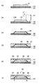
図1は、本発明の第1実施形態に係る光導波路コアを備える光導波路の製造方法を説明するための概略図である。図1(a)は、第1実施形態におけるコア部形成工程を説明するための概略断面図であり、図1(b)は、第1実施形態における凹部形成工程を説明するための概略断面図であり、図1(c)は、第1実施形態における金属層形成工程を説明するための概略図であり、図1(d)は、第1実施形態における金属層除去工程を説明するための概略図であり、図1(e)は、形成された光導波路を示す概略断面図である。 FIG. 1 is a schematic diagram for explaining a method of manufacturing an optical waveguide including an optical waveguide core according to the first embodiment of the present invention. FIG. 1A is a schematic cross-sectional view for explaining a core portion forming step in the first embodiment, and FIG. 1B is a schematic cross-sectional view for explaining a recess forming step in the first embodiment. FIG. 1C is a schematic diagram for explaining the metal layer forming step in the first embodiment, and FIG. 1D is a diagram for explaining the metal layer removing step in the first embodiment. FIG. 1E is a schematic cross-sectional view showing the formed optical waveguide.
本発明の第1実施形態に係る光導波路の製造方法としては、まず、図1(a)に示すように、第1クラッド層(下部クラッド層)12を備えた基板11の、前記第1クラッド層12上にコア部13を形成する。
As a method of manufacturing an optical waveguide according to the first embodiment of the present invention, first, as shown in FIG. 1A, the first cladding of a
具体的には、まず、基板11の表面に第1クラッド層12を形成する。
Specifically, first, the
前記基板11としては、各種有機基板や無機基板が特に限定なく用いられる。有機基板の具体例としては、エポキシ基板、アクリル基板、ポリカーボネート基板、及びポリイミド基板等が挙げられる。また、無機基板としては、シリコン基板やガラス基板等が挙げられる。また、基板上に予め回路が形成されたプリント回路基板のようなものであってもよい。
As the
前記第1クラッド層12の形成方法としては、前記基板11の表面に、前記第1クラッド層12を形成するための所定の屈折率を有する硬化性樹脂材料からなる樹脂フィルムを貼り合せた後、硬化させる方法や、前記第1クラッド層12を形成するための液状の硬化性樹脂材料を塗布した後、硬化させる方法や、前記第1クラッド層12を形成するための硬化性樹脂材料のワニスを塗布した後、硬化させる方法等が挙げられる。なお、前記第1クラッド層12を形成させる際には、密着性を高めるために、予め、前記基板11の表面にプラズマ処理等を施しておくことが好ましい。
As a method of forming the
前記第1クラッド層12を形成するための硬化性樹脂材料としては、後に形成されるコア部13の材料よりも導波光の伝送波長における屈折率が低くなるようなものが用いられる。その伝送波長における屈折率としては、例えば、1.5〜1.55程度のものが挙げられる。このような硬化性樹脂材料の種類としては、上記のような屈折率を有する、エポキシ系樹脂、アクリル系樹脂、ポリカーボネート系樹脂、ポリイミド系樹脂等が挙げられる。
As the curable resin material for forming the
前記第1クラッド層12の厚みは、特に限定されないが、例えば、5〜15μm程度であることが好ましい。
The thickness of the
前記第1クラッド層12を形成する具体的な方法としては、例えば、前記第1クラッド層12を形成するために樹脂フィルムを貼り合せた後、硬化させる方法や、前記第1クラッド層12を形成するための、液状の硬化性樹脂材料、又は、硬化性樹脂材料のワニスを塗布した後、硬化させる方法等が用いられる。
As a specific method for forming the
前記第1クラッド層12を形成するために樹脂フィルムを貼り合せた後、硬化させる具体的な方法としては、例えば、以下のような方法が用いられる。まず、前記基板11表面に硬化性樹脂からなる樹脂フィルムを重ねるように載置した後、加熱プレスにより貼り合せる、又は、前記基板11表面に硬化性樹脂からなる樹脂フィルムを、透明性の接着剤により貼り合わせる。そして、貼り合せられた樹脂フィルムに光を照射すること、又は、加熱することにより硬化させる。
For example, the following method is used as a specific method of curing after the resin film is bonded to form the
また、前記第1クラッド層12を形成するための、液状の硬化性樹脂材料、または、硬化性樹脂材料のワニスを塗布した後、硬化させる具体的な方法としては、例えば、以下のような方法が用いられる。まず、前記基板11表面に液状の硬化性樹脂材料又は硬化性樹脂材料のワニスを、スピンコート法、バーコート法、又は、ディップコート法等を用いて塗布させる。そして、塗布された液状の硬化性樹脂材料又は硬化性樹脂材料のワニスに光を照射すること、又は、加熱することにより硬化させる。
In addition, as a specific method of curing after applying a liquid curable resin material or a varnish of the curable resin material for forming the
次に、形成された前記第1クラッド層12の外表面に、感光性材料からなるコア材料層を形成する。
Next, a core material layer made of a photosensitive material is formed on the outer surface of the formed
ここで、感光性材料とは、エネルギ線が照射された部分の、後述する現像で用いる液体に対する溶解性が変化する材料である。具体的には、例えば、エネルギ線を照射する前には、後述する現像で用いる液体に対して溶解しにくいが、エネルギ線を照射した後には、溶解しやすくなる材料や、エネルギ線を照射する前には、後述する現像で用いる液体に対して溶解しやすいが、エネルギ線を照射した後には、溶解しにくくなる材料等が挙げられる。また、感光性材料とは、具体的には、例えば、感光性高分子材料等が挙げられる。また、エネルギ線とは、溶解性を変化させることができるものであれば、特に限定されないが、取扱の容易さ等から、紫外線が好ましく用いられる。感光性材料としては、一般的に、紫外線が照射された部分の、前記溶解性が変化する感光性高分子材料が好ましく用いられる。より具体的には、紫外線が照射された部分が硬化されて、後述する現像で用いる液体に対して溶解しにくくなる感光性高分子材料が好ましく用いられる。 Here, the photosensitive material is a material in which the solubility of a portion irradiated with energy rays with respect to a liquid used in development described later changes. Specifically, for example, before irradiating energy rays, it is difficult to dissolve in a liquid used in development described later, but after irradiating energy rays, materials that are easily dissolved or energy rays are irradiated. Before, it is easy to melt | dissolve with respect to the liquid used by the image development mentioned later, but after irradiating an energy ray, the material etc. which become difficult to melt | dissolve are mentioned. Specific examples of the photosensitive material include a photosensitive polymer material. The energy ray is not particularly limited as long as it can change the solubility, but ultraviolet rays are preferably used from the viewpoint of ease of handling. As the photosensitive material, generally, a photosensitive polymer material whose solubility is changed in a portion irradiated with ultraviolet rays is preferably used. More specifically, a photosensitive polymer material that is hard to dissolve in a liquid used in development described later is preferably used by curing the portion irradiated with ultraviolet rays.
前記コア材料層の形成方法としては、前記第1クラッド層12の外表面に、前記コア材料層を形成するための所定の屈折率を有する感光性高分子材料からなる樹脂フィルム(感光性フィルム)を貼り合せる方法や、前記コア材料層を形成するための液状の感光性高分子材料を塗布する方法や、前記コア材料層3を形成するための感光性高分子材料のワニスを塗布した後、乾燥させる方法等が挙げられる。なお、前記コア材料層を形成させる際にも、前記第1クラッド層12の外表面を活性化させて密着性を高めるために、予め、プラズマ処理等を施しておくことが好ましい。
As a method for forming the core material layer, a resin film (photosensitive film) made of a photosensitive polymer material having a predetermined refractive index for forming the core material layer on the outer surface of the
前記感光性高分子材料からなる樹脂フィルム(感光性フィルム)としては、半硬化状態の感光性高分子材料をポリエチレンテレフタレート(PET)フィルム等に塗布して得られるドライフィルム等が挙げられる。なお、このようなドライフィルムは、通常、保護フィルムにより保護されている。 Examples of the resin film (photosensitive film) made of the photosensitive polymer material include a dry film obtained by applying a semi-cured photosensitive polymer material to a polyethylene terephthalate (PET) film or the like. Such a dry film is usually protected by a protective film.
前記コア材料層を形成するための感光性高分子材料としては、前記第1クラッド層12の材料よりも導波光の伝送波長における屈折率が高いものが用いられる。その伝送波長における屈折率としては、例えば、1.55〜1.6程度のものが挙げられる。
As the photosensitive polymer material for forming the core material layer, a material having a higher refractive index at the transmission wavelength of the guided light than the material of the
前記コア材料層を形成するための感光性高分子材料の種類としては、上記のような屈折率を有する、エポキシ系樹脂、アクリル系樹脂、ポリカーボネート系樹脂、ポリイミド系樹脂等を樹脂成分とする感光性材料が挙げられる。これらの中でも特に、ビスフェノール型エポキシ樹脂が好ましく、前記コア材料層を形成するための感光性高分子材料としては、ビスフェノール型エポキシ樹脂と光カチオン硬化剤とを含有する樹脂組成物が、耐熱性の高い導波路が得られるために、プリント基板等と複合化することができる点から好ましい。なお、前記コア材料層と前記第1クラッド層12との接着性の観点から、前記コア材料層を形成するための感光性高分子材料は、前記第1クラッド層12を形成するための硬化性樹脂材料と同系統のものであることが好ましい。
As a kind of the photosensitive polymer material for forming the core material layer, a photosensitive resin having an epoxy resin, an acrylic resin, a polycarbonate resin, a polyimide resin, or the like having a refractive index as described above as a resin component. Materials. Among these, bisphenol type epoxy resin is particularly preferable, and as the photosensitive polymer material for forming the core material layer, a resin composition containing a bisphenol type epoxy resin and a photocationic curing agent has a heat resistance. Since a high waveguide can be obtained, it is preferable because it can be combined with a printed circuit board or the like. From the viewpoint of adhesion between the core material layer and the
前記コア材料層の厚みは、特に限定されないが、例えば、20〜100μm程度であることが好ましい。 Although the thickness of the said core material layer is not specifically limited, For example, it is preferable that it is about 20-100 micrometers.
前記コア材料層を形成する具体的な方法としては、例えば、前記コア材料層を形成するために樹脂フィルムを貼り合せる方法や、前記コア材料層を形成するための、液状の硬化性樹脂材料、又は、硬化性樹脂材料のワニスを塗布する方法等が用いられる。 As a specific method of forming the core material layer, for example, a method of bonding a resin film to form the core material layer, a liquid curable resin material for forming the core material layer, Alternatively, a method of applying a varnish of a curable resin material is used.
前記コア材料層を形成するために樹脂フィルムを貼り合せる具体的な方法としては、例えば、前記第1クラッド層12の外表面に硬化性樹脂からなる樹脂フィルムを重ねるように載置した後、加熱プレスにより貼り合せる、又は、前記第1クラッド層12の外表面に硬化性樹脂からなる樹脂フィルムを、透明性の接着剤により貼り合わせる。
As a specific method of laminating a resin film to form the core material layer, for example, after placing a resin film made of a curable resin on the outer surface of the
また、前記コア材料層を形成するための液状の硬化性樹脂材料、又は、硬化性樹脂材料のワニスを塗布する方法の具体的な方法としては、前記第1クラッド層12の外表面に液状の硬化性樹脂材料又は硬化性樹脂材料のワニスを、スピンコート法、バーコート法、又は、ディップコート法等を用いて塗布した後、必要に応じて乾燥させる。
In addition, as a specific method of applying the liquid curable resin material for forming the core material layer or the varnish of the curable resin material, a liquid is applied to the outer surface of the
前記コア材料層を露光して硬化等させる前に、前記コア材料層に熱処理を施してもよい。そうすることにより、前記コア材料層の表面の凹凸、気泡、ボイド等を消失させて平滑になる。熱処理温度は、前記コア材料層の表面の凹凸、気泡、ボイド等が消失して平滑になるような粘度になる温度が好ましく、前記コア材料層を形成する硬化性樹脂材料の種類によって適宜選択される。また、熱処理時間としては、10〜30分間程度であることが、上記効果が充分に得られる点から好ましい。なお、熱処理の手段は特に限定されず、所定の温度に設定したオーブン中で処理する方法やホットプレートで加熱する等の方法が用いられる。 Before the core material layer is exposed and cured, the core material layer may be subjected to heat treatment. By doing so, unevenness, bubbles, voids and the like on the surface of the core material layer are eliminated and smoothed. The heat treatment temperature is preferably a temperature at which the unevenness, bubbles, voids, etc. on the surface of the core material layer disappear and become smooth, and is appropriately selected depending on the type of curable resin material forming the core material layer. The Moreover, as heat processing time, it is preferable that it is about 10 to 30 minutes from the point from which the said effect is fully acquired. The means for heat treatment is not particularly limited, and a method such as a method of treating in an oven set at a predetermined temperature or a method of heating with a hot plate is used.
次に、前記コア材料層に対して、フォトマスクを介して露光光を照射して、前記コア材料層に対して所定形状のパターン露光を行う。また、前記露光は、感光性材料を光により変質(硬化等)させうる波長の光を必要な光量で露光する方法であれば、特に限定なく用いることができる。具体的には、例えば、前記露光光として、紫外線等のエネルギ線を用いる方法等が挙げられる。そして、取扱の容易さ等から、紫外線が好ましく用いられる。また、フォトマスクを前記コア材料層の表面に接触するように載置して露光するコンタクト露光や、前記コア材料層の外表面に接触しないように所定の間隔を保持した状態で露光する投影型露光等の、何れの露光方法を用いてもよい。 Next, the core material layer is irradiated with exposure light through a photomask to perform pattern exposure of a predetermined shape on the core material layer. Further, the exposure can be used without any particular limitation as long as it is a method of exposing light having a wavelength capable of deteriorating (curing, etc.) the photosensitive material with light with a necessary amount of light. Specifically, for example, a method of using energy rays such as ultraviolet rays as the exposure light may be used. In view of ease of handling, ultraviolet rays are preferably used. Also, contact exposure in which a photomask is placed so as to be in contact with the surface of the core material layer and exposure, and projection type in which exposure is performed while maintaining a predetermined interval so as not to contact the outer surface of the core material layer Any exposure method such as exposure may be used.
また、露光条件としては、感光性材料の種類に応じて適宜選択されるが、例えば、前記露光光として、365nm程度の紫外光を用い、500〜3500mJ/cm2となるように露光する条件等が選ばれる。 The exposure conditions are appropriately selected according to the type of the photosensitive material. For example, as the exposure light, ultraviolet light having a wavelength of about 365 nm is used, and exposure conditions are set to 500 to 3500 mJ / cm 2. Is selected.
そして、前記露光後に、熱による後キュアを行うことも硬化を確実にする点から有効である。後キュアの条件としては、温度80〜160℃程度、時間20〜120分間程度が好ましい。しかしながら、特にこの範囲に限られるものでは無く、感光性材料によって最適化することが重要であることは言うまでもない。 Further, after the exposure, post-curing with heat is also effective from the viewpoint of ensuring curing. As post-curing conditions, a temperature of about 80 to 160 ° C. and a time of about 20 to 120 minutes are preferable. However, it is not particularly limited to this range, and it is needless to say that optimization by the photosensitive material is important.
次に、現像処理を行うことにより、図1(a)に示すような、コア部13を形成する。
Next, a
前記現像処理としては、前記コア材料層の感光性材料がポジ型の場合には、露光されなかった部分、ネガ型の場合には、露光された部分を現像液で洗い流すことにより、不要な部分を除去する工程である。前記現像液としては、例えば、アセトンやイソプロピルアルコール、トルエン、エチレングリコール、又は、これらを所定割合で混合させたもの等が挙げられる。さらに、例えば、特開2007−292964号公報で開示されているような水系の現像液も好ましく用いられうる。現像方法としてはスプレーにより現像液を噴射する方法や超音波洗浄を利用する方法等が挙げられる。 As the development process, when the photosensitive material of the core material layer is a positive type, an unexposed part is washed away with a developer, and an unexposed part is washed away with a developer. This is a step of removing. Examples of the developer include acetone, isopropyl alcohol, toluene, ethylene glycol, or a mixture of these at a predetermined ratio. Further, for example, an aqueous developer as disclosed in JP-A-2007-292964 can be preferably used. Examples of the developing method include a method of spraying a developer by spraying and a method using ultrasonic cleaning.
次に、図1(b)に示すように、刃先の一方の面が、刃の面方向に平行な面で、他方の面が、刃の面方向に対する角度が所定の角度、例えば、45°である面である刃14を用いて、前記コア部13を切り込んで、凹部15を形成する。すなわち、前記刃14を、前記コア部13に対して略垂直となるように回転させながら、前記コア部に垂下させる。その際、凹部15が、前記第1クラッド層12に対して略垂直な垂直面15aと、前記垂直面15aに対向し、前記第1クラッド層12の反対側から入射される光を前記コア部13内に誘導又は前記コア部13から出射される光を前記第1クラッド層12の反対側に導出するように、光を反射させるための傾斜面15bとを有する凹部15となるように、前記コア部13を切り込む。前記凹部15は、前記第1クラッド層12に平行な断面積が前記第1クラッド層12に近づくほど徐々に小さくなるように、前記傾斜面15bが形成している。なお、前記刃14は、円盤状の回転刃物であって、円周部に刃先があるもの、例えば、ダイシングブレード等が用いられる。また、凹部15の形状は、垂直面15aと前記傾斜面15bとが対向するように形成されたものであれば、特に限定されず、例えば、溝状である。
Next, as shown in FIG. 1B, one surface of the blade edge is a surface parallel to the surface direction of the blade, and the other surface has a predetermined angle with respect to the surface direction of the blade, for example, 45 °. The
前記コア部13を前記刃14で切り込む際、必要に応じて、前記基板11や前記刃14等を加熱することにより、前記コア部13を軟化させながら切り込んでもよい。また、前記刃14の刃先が、前記第1クラッド層12に達するように切り込んでも、達しないように切り込んでもよい。
When cutting the
次に、図1(c)に示すように、上記のようにして形成された凹部15に、金属層16を形成させる。金属層を形成させる方法としては、特に限定されず、公知の方法を用いることができる。具体的には、例えば、真空蒸着法等の蒸着法、スパッタ法、及びナノペースト法等が挙げられる。
Next, as shown in FIG. 1C, a
前記金属層16の厚みとしては、光を反射させることができれば、特に限定されず、例えば、1000Å程度の厚み等が挙げられる。
The thickness of the
なお、前記傾斜面15bのみに金属層16を均一に形成することは困難である。このことは、特に前記凹部15が小さい場合に顕著である。そこで、前記傾斜面15b上には少なくとも金属層16が形成されるように、前記傾斜面15b上の金属層16bを形成し、前記垂直面15a上にも金属層16aが形成されていてもよい。そうすることによって、前記凹部15が小さくても、前記傾斜面15b上に金属層16bを均一に形成することができる。そして、後述する金属層除去工程によって、前記垂直面15a上の金属層16aを選択的に除去することができる。
It is difficult to uniformly form the
また、前記金属層16を形成させる前に、前記コア部13の表面に粗化処理を施してもよい。そうすることによって、前記金属層16が前記凹部15に形成されやすくなる。粗化処理方法としては、特に限定されない。具体的には、例えば、過マンガン酸処理液を用いたマイクロエッチング処理等の、マイクロエッチング処理等が挙げられる。
Further, before the
また、前記金属層16を形成させる前に、前記コア部13の表面をカップリング剤で処理してもよい。そうすることによって、前記金属層16が前記凹部15に形成されやすくなる。前記カップリング剤での処理方法としては、特に限定されない。具体的には、例えば、前記コア部13の表面にカップリング剤を塗布した後に熱処理を施す方法等が挙げられる。また、前記カップリング剤としては、特に限定されず、公知のカップリング剤を用いることができる。具体的には、例えば、分子内にアミノ基を有するシランカップリング剤等が挙げられる。
In addition, before the
また、前記粗化処理及び前記カップリング剤での処理は、いずれか一方だけを行ってもよいし、両方行ってもよい。具体的には、前記粗化処理を施した後に、前記カップリング剤での処理を施してもよい。そうすることによって、前記金属層16が前記凹部15により形成されやすくなる。
Moreover, only one or both of the roughening treatment and the treatment with the coupling agent may be performed. Specifically, after the roughening treatment, the treatment with the coupling agent may be performed. By doing so, the
次に、図1(d)に示すように、前記刃14を用いて、前記垂直面15a上の金属層16aを切り込んで、前記金属層16aを選択的に除去する。その際、前記刃14を、前記16aが除去されるように切り込んでいればよく、前記コア部13も切り込まれていてもよい。すなわち、前記垂直面15a上に形成された金属層16aを、その外表面を基準として前記金属層16aの厚み分以上除去するように、前記刃14の位置を調整して、切り込む。そうすることによって、前記傾斜面15b上の金属層16bが残存し、前記垂直面15a上の金属層16aが除去される。この残存した金属層16bが、前記第1クラッド層12の反対側から入射される光を前記コア部13内に誘導又は前記コア部13から出射された光を前記第1クラッド層12の反対側に導出するように、光を反射させるミラー(ミクロミラー)として働く。
Next, as shown in FIG. 1 (d), the
そして、最後に、図1(e)に示すように、上記のように形成されたコア部13を埋設するように、第2クラッド層(上部クラッド層)17を形成することにより、光導波路18が形成される。
And finally, as shown in FIG.1 (e), by forming the 2nd cladding layer (upper cladding layer) 17 so that the
前記第2クラッド層17の形成方法としては、前記コア部13を埋設するように、前記第2クラッド層17を形成するための液状の硬化性樹脂材料を塗布した後、光、熱等で硬化させる方法や、前記第2クラッド層17を形成するための硬化性樹脂材料のワニスを塗布した後、光、熱等で硬化させる方法や、前記第2クラッド層17を形成するための硬化性樹脂材料からなる樹脂フィルムを貼り合せた後、光、熱等で硬化させる方法、等が挙げられる。
As a method of forming the
前記第2クラッド層17を形成するための硬化性樹脂材料としては、前記コア部13の材料よりも導波光の伝送波長における屈折率が低くなるような硬化性樹脂材料であれば、特に限定なく用いられ、通常は、前記第1クラッド層12を形成した材料と同様の種類の硬化性樹脂材料が用いられる。
The curable resin material for forming the
また、前記第2クラッド層17の厚みとしては、特に限定されないが、前記コア部13の上に前記第1クラッド層12と同程度の厚みであることが好ましい。
Further, the thickness of the
上記のような工程を経て、図1(e)に示すような光導波路18が形成される。なお、図1(e)中の矢符は、光導波路18に入射して出射される導波光の光路を示す。
Through the steps as described above, the
形成された光導波路18は、前記コア部13とこれを被覆するクラッド層(前記第1クラッド層12及び前記第2クラッド層17)によって形成されたものであり、前記コア部13はクラッド層よりも屈折率が高く、内部を伝搬する光を全反射によってコア内に閉じこめるものである。このような光導波路18は、主としてマルチモード導波路として形成される。前記光導波路18の前記コア部13のサイズは、例えば、20〜100μmの矩形形状、コア部を含む層の厚みを除いた下部の第1クラッド層12及び上部の第2クラッド層17の厚みはそれぞれ5〜15μm、コア部とクラッド層との屈折率差は0.5〜3%程度が適当であるがこれに限られるものではない。
The formed
[第2実施形態]
次に、前記コア部形成工程が、基板上に形成されたクラッド層の表面に、感光性材料からなるコア材料層を形成するコア材料層形成工程と、前記コア材料層を選択露光することによって、前記感光性材料が硬化した硬化部とそれ以外の未硬化部とを有するコア部を形成する露光工程とを備え、前記凹部形成工程が、前記傾斜面が前記硬化部に、前記垂直面が前記未硬化部に形成されるように、前記凹部を形成する工程であり、前記金属層除去工程が、前記凹部が形成されたコア部を現像することによって、前記垂直面上の金属層を除去し、前記傾斜面上の金属層を残存させる工程である場合の実施形態について説明する。本発明の第1実施形態である光導波路コアを備える光導波路の製造方法と対応する部分には、同一の参照符号を付し、重複部分については詳細な説明を省略する。
[Second Embodiment]
Next, the core part forming step includes a core material layer forming step of forming a core material layer made of a photosensitive material on the surface of the clad layer formed on the substrate, and selectively exposing the core material layer. An exposure step of forming a core portion having a cured portion obtained by curing the photosensitive material and an uncured portion other than the cured portion, wherein the concave portion forming step includes the inclined surface as the cured portion and the vertical surface as the vertical surface. Forming the recess so as to be formed in the uncured portion, and the metal layer removing step removes the metal layer on the vertical surface by developing the core portion on which the recess is formed. An embodiment in which the metal layer on the inclined surface is left will be described. Portions corresponding to those of the manufacturing method of the optical waveguide having the optical waveguide core according to the first embodiment of the present invention are denoted by the same reference numerals, and detailed description of overlapping portions is omitted.
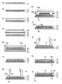
図2は、本発明の第2実施形態に係る光導波路コアを備える光導波路の製造方法を説明するための概略図である。図2(a)は、第2実施形態におけるコア部形成工程を説明するための概略断面図であり、図2(b)は、第2実施形態における凹部形成工程を説明するための概略断面図であり、図2(c)は、第2実施形態における金属層形成工程を説明するための概略図であり、図2(d)及び図2(e)は、第2実施形態における金属層除去工程を説明するための概略図であり、図2(f)は、形成された光導波路を示す概略断面図である。 FIG. 2 is a schematic view for explaining a method of manufacturing an optical waveguide including an optical waveguide core according to the second embodiment of the present invention. FIG. 2A is a schematic cross-sectional view for explaining a core portion forming step in the second embodiment, and FIG. 2B is a schematic cross-sectional view for explaining a recess forming step in the second embodiment. FIG. 2C is a schematic view for explaining a metal layer forming step in the second embodiment, and FIGS. 2D and 2E are metal layer removal in the second embodiment. It is the schematic for demonstrating a process, FIG.2 (f) is a schematic sectional drawing which shows the formed optical waveguide.
本発明の第2実施形態に係る光導波路の製造方法としては、まず、図2(a)に示すように、第1クラッド層(下部クラッド層)12を備えた基板11の、前記第1クラッド層12上にコア部13を形成する。その際、前記コア部13として、硬化部13aと未硬化部13bとを形成する。
As a method of manufacturing an optical waveguide according to the second embodiment of the present invention, first, as shown in FIG. 2A, the first cladding of a
具体的には、まず、第1実施形態と同様、基板11の表面に第1クラッド層12を形成する。
Specifically, first, as in the first embodiment, the
次に、第1実施形態と同様、形成された前記第1クラッド層12の外表面に、感光性材料からなるコア材料層を形成する。
Next, as in the first embodiment, a core material layer made of a photosensitive material is formed on the outer surface of the formed
次に、前記コア材料層に対して、フォトマスクを介して露光光を照射して、前記コア材料層に対して所定形状のパターン露光を行う。そうすることによって、図2(a)に示すように、硬化部13aと未硬化部13bとを有するコア部13が形成される。具体的には、例えば、前記コア材料層の感光性材料がポジ型の場合には、露光された部分が硬化部13aとなり、露光されなかった部分が未硬化部13bとなるようなコア部13が形成される。また、前記コア材料層の感光性材料がネガ型の場合には、露光された部分が未硬化部13bとなり、露光されなかった部分が硬化部13aとなるようなコア部13が形成される。
Next, the core material layer is irradiated with exposure light through a photomask to perform pattern exposure of a predetermined shape on the core material layer. By doing so, as shown to Fig.2 (a), the
また、前記露光は、感光性材料を光により変質(硬化等)させうる波長の光を必要な光量で露光する方法であれば、特に限定なく用いることができる。具体的には、例えば、第1実施形態と同様の方法を用いることができる。 Further, the exposure can be used without any particular limitation as long as it is a method of exposing light having a wavelength capable of deteriorating (curing, etc.) the photosensitive material with light with a necessary amount of light. Specifically, for example, the same method as in the first embodiment can be used.
また、露光条件としては、感光性材料の種類に応じて適宜選択されるが、例えば、第1実施形態と同様の条件が選ばれる。 Further, the exposure conditions are appropriately selected according to the type of the photosensitive material. For example, the same conditions as in the first embodiment are selected.
そして、第1実施形態と同様、前記露光後に、熱による後キュアを行うことも硬化を確実にする点から有効である。後キュアの条件としては、例えば、第1実施形態と同様の条件が選ばれる。 As in the first embodiment, after-exposure, post-curing with heat is also effective from the viewpoint of ensuring curing. As the post-curing conditions, for example, the same conditions as in the first embodiment are selected.
次に、図2(b)に示すように、刃先の一方の面が、刃の面方向に平行な面で、他方の面が、刃の面方向に対する角度が所定の角度、例えば、45°である面である刃14を用いて、前記コア部13を切り込んで、凹部15を形成する。すなわち、前記刃14を、前記コア部13に対して略垂直となるように回転させながら、前記コア部に垂下させる。その際、凹部15が、前記第1クラッド層12に対して略垂直な垂直面15aと、前記垂直面15aに対向し、前記第1クラッド層12の反対側から入射される光を前記コア部13内に誘導又は前記コア部13から出射される光を前記第1クラッド層12の反対側に導出するように、光を反射させるための傾斜面15bとを有する凹部15となるように、前記コア部13を切り込む。さらに、前記垂直面15aが未硬化部13bに、前記傾斜面15bが硬化部13aに形成されるように、前記コア部13を切り込む。前記凹部15は、前記第1クラッド層12に平行な断面積が前記第1クラッド層12に近づくほど徐々に小さくなるように、前記傾斜面15bが形成している。なお、凹部15の形状は、垂直面15aと前記傾斜面15bとが対向するように形成されたものであれば、特に限定されず、例えば、溝状である。
Next, as shown in FIG. 2B, one surface of the blade edge is a surface parallel to the surface direction of the blade, and the other surface has a predetermined angle with respect to the surface direction of the blade, for example, 45 °. The
前記コア部13を前記刃14で切り込む際、必要に応じて、前記基板11や前記刃14等を加熱することにより、前記コア部を軟化させながら切り込んでもよい。また、前記刃14の刃先が、前記第1クラッド層12に達するように切り込んでも、達しないように切り込んでもよい。
When cutting the
次に、図2(c)に示すように、上記のようにして形成された凹部15に、金属層16を形成させる。金属層を形成させる方法としては、特に限定されず、例えば、第1実施形態と同様の方法を用いることができる。
Next, as shown in FIG. 2C, a
前記金属層16の厚みとしては、光を反射させることができれば、特に限定されず、例えば、第1実施形態と同様の厚みであればよい。
The thickness of the
なお、前記傾斜面15bのみに金属層16を均一に形成することは、第1実施形態と同様、困難である。そこで、本実施形態においては、第1実施形態と同様、前記凹部15が小さくても、前記傾斜面15b上に金属層16bを均一に形成することができる。
In addition, it is difficult to form the
また、前記金属層16が前記凹部15に形成されやすくするために、第1実施形態と同様、前記金属層16を形成させる前に、前記コア部13の表面に粗化処理を施してもよいし、前記コア部13の表面をカップリング剤で処理してもよい。また、前記粗化処理及び前記カップリング剤での処理は、第1実施形態と同様、いずれか一方だけを行ってもよいし、両方行ってもよい。粗化処理方法及びカップリング剤での処理方法としては、特に限定されない。具体的には、例えば、第1実施形態と同様の方法を用いることができる。
Further, in order to facilitate the formation of the
次に、図2(d)に示すように、現像処理を行う。そうすることによって、図2(e)に示すような、コア部13を形成する。
Next, development processing is performed as shown in FIG. By doing so, the
前記現像処理としては、第1実施形態と同様の方法を用いることができる。具体的には、例えば、図2(d)に示すように、基板11を含めた全体を、現像液21に浸漬させる方法等が挙げられる。
As the development processing, the same method as in the first embodiment can be used. Specifically, for example, as shown in FIG. 2 (d), a method of immersing the
前記のような現像処理を施すことによって、前記未硬化部13bが除去されるとともに、前記未硬化部13b上の金属層16a、すなわち、垂直面15a上の金属層16aが選択的に除去される。そうすることによって、前記傾斜面15b上の金属層16bが残存し、前記垂直面15a上の金属層16aが除去される。この残存した金属層16bが、前記第1クラッド層12の反対側から入射される光を前記コア部13内に誘導又は前記コア部13から出射された光を前記第1クラッド層12の反対側に導出するように、光を反射させるミラー(ミクロミラー)として働く。
By performing the development process as described above, the
そして、最後に、図2(f)に示すように、第1実施形態と同様、上記のように形成されたコア部13を埋設するように、第2クラッド層(上部クラッド層)17を形成することにより、光導波路18が形成される。
Finally, as shown in FIG. 2 (f), as in the first embodiment, the second cladding layer (upper cladding layer) 17 is formed so as to embed the
上記のような工程を経て、図2(f)に示すような光導波路18が形成される。なお、図2(f)中の矢符は、光導波路18に入射して出射される導波光の光路を示す。
Through the steps as described above, an
形成された光導波路18は、前記コア部13とこれを被覆するクラッド層(前記第1クラッド層12及び前記第2クラッド層17)によって形成されたものであり、前記コア部13はクラッド層よりも屈折率が高く、内部を伝搬する光を全反射によってコア内に閉じこめるものである。このような光導波路18は、主としてマルチモード導波路として形成される。前記光導波路18の前記コア部13のサイズは、例えば、20〜100μmの矩形形状、コア部を含む層の厚みを除いた下部の第1クラッド層12及び上部の第2クラッド層17の厚みはそれぞれ5〜15μm、コア部とクラッド層との屈折率差は0.5〜3%程度が適当であるがこれに限られるものではない。
The formed
また、上記第1実施形態及び第2実施形態における光導波路を、電気回路が予め形成された基板上に形成させることによって、光電気複合配線板が得られる。具体的には、例えば、基板11として、電気回路が予め形成された基板を用いること等によって、形成される。
Moreover, an optical / electrical composite wiring board is obtained by forming the optical waveguide in the first embodiment and the second embodiment on a substrate on which an electric circuit is previously formed. Specifically, for example, the
次に、本発明に係る上記実施形態と比較するため比較用の実施形態として、光導波路コアを形成する工程と、前記光導波路コアを回転刃等により加工することにより、前記光導波路コアに傾斜面を形成する工程と、前記傾斜面の反射効率を向上させるために、前記傾斜端上に金属層を形成する工程とを備える、従来の光導波路の製造方法について説明する。 Next, as a comparative embodiment for comparison with the above-described embodiment according to the present invention, a step of forming an optical waveguide core, and the optical waveguide core is inclined by processing the optical waveguide core with a rotary blade or the like. A conventional optical waveguide manufacturing method including a step of forming a surface and a step of forming a metal layer on the inclined end in order to improve the reflection efficiency of the inclined surface will be described.
図3は、従来の光導波路の製造方法を説明するための概略図である。図3(a)は、従来の光導波路の製造方法における、仮基板上に形成された第1クラッド層の表面へのコア部の形成を説明するための概略断面図であり、図3(b)は、従来の光導波路の製造方法における、傾斜面の形成を説明するための概略断面図であり、図3(c)は、従来の光導波路の製造方法における、金属層の形成を説明するための概略図であり、図3(d)は、従来の光導波路の製造方法における、第2クラッド層の形成を説明するための概略図であり、図3(e)は、基板の貼り付けを説明するための概略図であり、図3(f)は、仮基板の剥離を説明するための概略図である。 FIG. 3 is a schematic view for explaining a conventional method of manufacturing an optical waveguide. FIG. 3A is a schematic cross-sectional view for explaining the formation of the core portion on the surface of the first cladding layer formed on the temporary substrate in the conventional method for manufacturing an optical waveguide, and FIG. ) Is a schematic cross-sectional view for explaining the formation of an inclined surface in a conventional method for manufacturing an optical waveguide, and FIG. 3C illustrates the formation of a metal layer in the conventional method for manufacturing an optical waveguide. FIG. 3D is a schematic diagram for explaining the formation of the second cladding layer in the conventional optical waveguide manufacturing method, and FIG. FIG. 3F is a schematic diagram for explaining the peeling of the temporary substrate.
まず、図3(a)に示すように、第1クラッド層(下部クラッド層)32を備えた仮基板31の、前記第1クラッド層32上にコア部33を形成する。基板11の代わりに、仮基板31を用いること以外、第1実施形態と同様に行うことができる。
First, as shown in FIG. 3A, the
次に、図3(b)に示すように、コア部33を回転刃34により加工することにより、前記コア部33に傾斜面33aを形成する。その際、傾斜面33aが、前記第1クラッド層33側から入射される光を前記コア部33内に誘導又は前記コア部33から出射される光を前記第1クラッド層32側に導出するような傾斜面である。
Next, as shown in FIG. 3B, the
次に、図3(c)に示すように、上記のようにして形成された傾斜面33aに、金属層36を形成させる。
Next, as shown in FIG. 3C, the
次に、図3(d)に示すように、第1実施形態と同様、上記のように形成されたコア部33を埋設するように、第2クラッド層(上部クラッド層)37を形成する。
Next, as shown in FIG. 3D, as in the first embodiment, a second cladding layer (upper cladding layer) 37 is formed so as to embed the
次に、図3(e)に示すように、第2クラッド層(上部クラッド層)37上に、基板38を貼着する。
Next, as shown in FIG. 3 (e), a
そして、最後に、図3(f)に示すように、仮基板31を剥離する。
Finally, the
上記のような工程を経て、図3(f)に示すような光導波路39が形成される。なお、図3(f)中の矢符は、光導波路39に入射して出射される導波光の光路を示す。
Through the steps as described above, an
このような製造方法によれば、導波光が前記第1クラッド層32を通過することになるので、仮基板31を剥離したり、本来、光導波路を形成しようとしていた基板を貼り付ける必要がある。これに対して、本実施形態に係る光導波路コアの製造方法によれば、これらの工程が不要となり、製造効率が高まる。
According to such a manufacturing method, since the guided light passes through the
以上のことから、本実施形態に係る光導波路コアの製造方法によれば、所定の角度をなす傾斜面を有する光導波路コアを効率的に製造することができ、前記傾斜面に選択的に金属膜を形成させることができる光導波路コアの製造方法を提供することができる。 From the above, according to the method for manufacturing an optical waveguide core according to the present embodiment, an optical waveguide core having an inclined surface having a predetermined angle can be efficiently manufactured, and a metal is selectively applied to the inclined surface. An optical waveguide core manufacturing method capable of forming a film can be provided.
以下、本発明を実施例によりさらに具体的に説明する。なお、本発明の範囲は実施例により何ら限定されるものではない。 Hereinafter, the present invention will be described more specifically with reference to examples. The scope of the present invention is not limited by the examples.
はじめに、本実施例で用いた光硬化性樹脂シートの製造方法について説明する。 First, the manufacturing method of the photocurable resin sheet used by the present Example is demonstrated.
(下部クラッド層用光硬化性樹脂シートAの製造)
ポリプロピレングリコールグリシジルエーテル(東都化成(株)製「PG207」)7質量部、液状の水添ビスフェノールA型エポキシ樹脂(ジャパンエポキシレジン(株)製「YX8000」)25質量部、固形の水添ビスフェノールA型エポキシ樹脂(ジャパンエポキシレジン(株)製「YL7170」)20質量部、2,2−ビス(ヒドロキシメチル)−1−ブタノールの1,2−エポキシ−4−(2−オキシラニル)シクロヘキサン付加物(ダイセル化学工業(株)製「EHPE3150」)8質量部、固形ビスフェノールA型エポキシ樹脂(ジャパンエポキシレジン(株)製「エピコート1006FS」)2質量部、フェノキシ樹脂(東都化成(株)製「YP50」)20質量部、光カチオン硬化開始剤((株)アデカ製「SP170」)0.5質量部、熱カチオン硬化開始剤(三新化学工業(株)製「SI−150L」)0.5質量部、表面調整剤(DIC(株)製「F470」)0.1質量部の各配合成分を、トルエン30質量部、MEK70質量部の溶剤に溶解し、孔径1μmのメンブランフィルタで濾過した後、減圧脱泡することによって、エポキシ樹脂ワニスを調製した。このエポキシ樹脂ワニスを厚み50μmのPETフィルムの上にバーコーターで塗工し、80℃で10分間、1次乾燥をしたあと、120℃で10分間、2次乾燥をした。最後に保護フィルムとして35μmのOPPフィルムで被覆した。このようにして得られた下部クラッド用光硬化性樹脂シートAは、膜厚15μmであり、波長579nmの光に対する屈折率は1.54であった。
(Manufacture of photocurable resin sheet A for lower clad layer)
7 parts by mass of polypropylene glycol glycidyl ether (“PG207” manufactured by Toto Kasei Co., Ltd.), 25 parts by mass of liquid hydrogenated bisphenol A type epoxy resin (“YX8000” manufactured by Japan Epoxy Resin Co., Ltd.), solid hydrogenated bisphenol A Type epoxy resin (“YL7170” manufactured by Japan Epoxy Resin Co., Ltd.) 20 parts by mass, 1,2-epoxy-4- (2-oxiranyl) cyclohexane adduct of 2,2-bis (hydroxymethyl) -1-butanol ( 8 parts by mass of “EHPE3150” manufactured by Daicel Chemical Industries, Ltd., 2 parts by mass of solid bisphenol A type epoxy resin (“Epicoat 1006FS” manufactured by Japan Epoxy Resin Co., Ltd.), “YP50” manufactured by Toto Kasei Co., Ltd. ) 20 parts by mass, photocationic curing initiator (“SP17” manufactured by Adeka Co., Ltd.) 0 ") 0.5 parts by mass, thermal cationic curing initiator (" SI-150L "manufactured by Sanshin Chemical Industry Co., Ltd.) 0.5 parts by mass, surface conditioner (" F470 "manufactured by DIC Corporation) 1 part by mass of each compounding component was dissolved in 30 parts by mass of toluene and 70 parts by mass of MEK, filtered through a membrane filter having a pore size of 1 μm, and then degassed under reduced pressure to prepare an epoxy resin varnish. This epoxy resin varnish was coated on a 50 μm thick PET film with a bar coater, subjected to primary drying at 80 ° C. for 10 minutes, and then secondary drying at 120 ° C. for 10 minutes. Finally, it was covered with a 35 μm OPP film as a protective film. The lower cladding photocurable resin sheet A thus obtained had a film thickness of 15 μm and a refractive index of 1.54 for light having a wavelength of 579 nm.
(コア部用光硬化性樹脂シートBの製造)
液状ビスフェノールA型エポキシ樹脂(DIC(株)製「エピクロン850S」)42質量部、固形ビスフェノールA型エポキシ樹脂(ジャパンエポキシレジン(株)製「エピコート1006FS」)55質量部、フェノキシ樹脂(東都化成(株)製「YP50」)3質量部、光カチオン硬化開始剤((株)アデカ製「SP170」)1質量部、表面調整剤(DIC(株)製「F470」)0.1質量部の各配合成分を、トルエン24質量部、MEK56質量部の溶剤に溶解し、孔径1μmのメンブランフィルタで濾過した後、減圧脱泡することによって、エポキシ樹脂ワニスを調製した。このエポキシ樹脂ワニスを上述した「光硬化性樹脂シートAの製造」と同様にしてフィルム化した。このようにして得られたコア部用光硬化性樹脂シートBは、膜厚40μmであり、波長579nmの光に対する屈折率は1.59であった。また、850nmにおける透過率は0.06dB/cmと充分に高い透明性を有していた。
(Manufacture of photocurable resin sheet B for core part)
42 parts by mass of liquid bisphenol A type epoxy resin (“Epiclon 850S” manufactured by DIC Corporation), 55 parts by mass of solid bisphenol A type epoxy resin (“Epicoat 1006FS” manufactured by Japan Epoxy Resin Co., Ltd.), phenoxy resin (Tohto Kasei ( Co., Ltd. “YP50”) 3 parts by mass, photocationic curing initiator (Adeca “SP170”) 1 part by mass, and surface conditioner (DIC “F470”) 0.1 part by mass The compounding component was dissolved in a solvent of 24 parts by mass of toluene and 56 parts by mass of MEK, filtered through a membrane filter having a pore diameter of 1 μm, and then degassed under reduced pressure to prepare an epoxy resin varnish. This epoxy resin varnish was formed into a film in the same manner as in “Production of photocurable resin sheet A” described above. The core portion photocurable resin sheet B thus obtained had a film thickness of 40 μm and a refractive index of 1.59 for light having a wavelength of 579 nm. Further, the transmittance at 850 nm was sufficiently high transparency of 0.06 dB / cm.
(上部クラッド層用光硬化性樹脂シートCの製造)
エポキシ樹脂ワニスの塗布厚みを変えた以外は、「光硬化性樹脂シートAの製造」と同様にしてフィルム化することにより上部クラッド用光硬化性樹脂シートCを得た。このようにして得られた光硬化性樹脂シートCは、膜厚55μmであり、波長579nmの光に対する屈折率は1.54であった。
(Manufacture of photocurable resin sheet C for upper clad layer)
Except changing the application | coating thickness of the epoxy resin varnish, the photocurable resin sheet C for upper clads was obtained by forming into a film like "manufacture of the photocurable resin sheet A". The photocurable resin sheet C thus obtained had a film thickness of 55 μm and a refractive index of 1.54 with respect to light having a wavelength of 579 nm.
(実施例1)
実施例1は、第1実施形態に係る実施例である。図4を参照して光導波路を製造する方法について説明する。なお、図4は、実施例1における光導波路の製造方法を説明するための模式図である。
Example 1
Example 1 is an example according to the first embodiment. A method of manufacturing an optical waveguide will be described with reference to FIG. FIG. 4 is a schematic diagram for explaining the method of manufacturing the optical waveguide in the first embodiment.
図4(a)に示すような、140mm×120mmのUV透過性ポリカーボネート樹脂からなる基板11に、下部クラッド層用光硬化性樹脂シートAを真空ラミネーター「V−130」で60℃、0.2MPaの条件でラミネートした。そして、光硬化性樹脂シートAの表面を超高圧水銀灯で2J/cm2の条件で紫外光を照射し、さらに150℃で30分間熱処理することにより、図4(b)に示すような、第1クラッド層(下部クラッド層)12が形成された。そして、形成された下部クラッド層12の表面に酸素プラズマ処理を施した。
As shown in FIG. 4A, a lower clad layer photocurable resin sheet A is applied to a
次に、図4(c)に示すように、下部クラッド層12の表面に、コア部用光硬化性樹脂シートBを真空ラミネーター「V−130」で60℃、0.2MPaの条件でラミネートすることにより、コア材料層41を形成した。
Next, as shown in FIG. 4C, the core photocurable resin sheet B is laminated on the surface of the lower
そして、図4(d)に示すように、直線パターンのスリットを有するフォトマスク42を、フォトマスク42のアライメントマークとコア材料層41の表面に形成したアライメントマークとを重ね合わせることにより位置決めを行って載置した。その後、照射光が略平行光になるように調整された超高圧水銀灯で3J/cm2の光量で紫外光をコア材料層41のスリットに対応する部分を光硬化させた。そうすることによって、図4(e)に示すように、光硬化させた部分(硬化部)13aと未硬化部13bとが形成される。その際、前記フォトマスク42としては、図7(a)に示すような、所定の幅W、所定の長さLの直線パターンのスリットの長手方向が平行に複数並んだ形状のものを用いた。幅W及び長さLは、40μm、120mmであった。なお、図7は、各実施例で用いるフォトマスクの形状を説明するための模式図であり、図7(a)は、実施例1で用いるフォトマスクの形状を説明するための模式図である。図7には、丸印で示した箇所を拡大した図面も併記した。
Then, as shown in FIG. 4D, a
次に、140℃で2分間熱処理を行ない、さらに、図4(e)に示すように、現像液43として55℃に調整した水系フラックス洗浄剤(荒川化学工業(株)製「パインアルファST−100SX」)を用い、その現像液43に浸漬させる現像処理することによって、未硬化部13bを溶解除去した。そして、さらに水で仕上げ洗浄してエアブローした後、100℃で10分間乾燥することによって、図4(f)に示すようなコア部13を形成した。
Next, heat treatment was performed at 140 ° C. for 2 minutes, and as shown in FIG. 4 (e), a water-based flux cleaning agent adjusted to 55 ° C. as developer 43 (“Pine Alpha ST-” manufactured by Arakawa Chemical Industries, Ltd.) was used. 100SX "), the
次に、図4(g)に示すように、刃先の一方の面が、刃の面方向に平行な面で、他方の面が、刃の面方向に対する角度が45°である面である刃(ダイシングブレード)14を用い、回転数15000rpmでコア部の両端部から110mmの位置を、2カ所切り込んだ。そうすることによって、45°傾斜面15bを有する凹部15が形成された。ダイシングブレード14としては、粒度5000番のものを用いた。
Next, as shown in FIG. 4G, a blade whose one surface is parallel to the surface direction of the blade and whose other surface is a surface whose angle with respect to the surface direction of the blade is 45 °. (Dicing blade) 14 was used, and two positions of 110 mm were cut from both ends of the core at a rotational speed of 15000 rpm. By doing so, the recessed
次に、図4(h)に示すように、凹部15が形成された領域のみが開口されたメタルマスク44でマスキングして、真空蒸着することによって、図4(i)に示すように、凹部15の表面に1000Å厚の金からなる金属層16を形成した。その後、図4(j)に示すように、前記刃14を用い、回転数15000rpmで、前記垂直面15a上に形成された金属層16aを、その外表面を基準として、10μm除去するように、前記刃14の位置を調整して、切り込んだ。そうすることによって、図4(j)に示すように、前記金属層16aを選択的に除去し、前記傾斜面15b上の金属層16bを残存させた。この残存した金属層16bが、前記第1クラッド層12の反対側から入射される光を前記コア部13内に誘導又は前記コア部13から出射された光を前記第1クラッド層12の反対側に導出するように、光を反射させるミラー(ミクロミラー)として働く。
Next, as shown in FIG. 4 (h), only the region where the
次に、図4(k)に示すように、下部クラッド層12及びコア部13を被覆するようにして、上部クラッド層用光硬化性樹脂シートCを真空ラミネーター「V−130」で80℃、0.3MPaの条件でラミネートした。
Next, as shown in FIG. 4 (k), the lower
そして、その後、超高圧水銀灯で2J/cm2の光量で露光し、さらに150℃30分間熱処理することにより、第2クラッド層(上部クラッド層)17を形成した。そうすることによって、図4(l)に示すように、下部クラッド層12とコア部13と上部クラッド層17とからなる光導波路18が形成された。なお、図4(l)中の矢符は、光導波路18に入射して出射される導波光の光路を示す。
Then, the second cladding layer (upper cladding layer) 17 was formed by exposing with an ultrahigh pressure mercury lamp at a light amount of 2 J / cm 2 and further heat treating at 150 ° C. for 30 minutes. By doing so, as shown in FIG. 4L, an
形成された光導波路について、以下に示す評価を行った。 The following evaluation was performed on the formed optical waveguide.
(導波路損失測定)
入力側端部、具体的には、一方のミラーが形成されている位置の、第2クラッド層に対して垂直の方向の、第2クラッド層の表面、(又は、光導波路の端部が露出している場合は、そのコア部の一方の端面)に、コア径10μmのNA0.21の光ファイバの端部を、マッチングオイル(シリコーンオイル)を介して、接続した。そして、出力側端部、具体的には、他方のミラーが形成されている位置の、第2クラッド層に対して垂直の方向の、第2クラッド層の表面、(又は、光導波路の端部が露出している場合は、そのコア部の他方の端面)に、コア径200μmのNA0.4の光ファイバの端部を、マッチングオイルを介して、接続した。LED光源からの光を、入力側端部に接続された光ファイバを介して、光導波路18に入射させた。そして、光導波路18からの出射光を、出力側端部に接続された光ファイバを介してパワーメータに入射させ、その出射光の光量P1を測定した。
(Waveguide loss measurement)
The input side end, specifically, the surface of the second cladding layer in the direction perpendicular to the second cladding layer at the position where one mirror is formed (or the end of the optical waveguide is exposed). In this case, the end of an optical fiber having a core diameter of 10 μm and NA of 0.21 was connected to one end surface of the core via matching oil (silicone oil). And the output side end, specifically, the surface of the second cladding layer in the direction perpendicular to the second cladding layer at the position where the other mirror is formed (or the end of the optical waveguide) Is exposed, the other end face of the core portion is connected to the end of an optical fiber having a core diameter of 200 μm and NA of 0.4 via matching oil. The light from the LED light source was made incident on the
一方、入力側端部に接続された光ファイバと出力側端部に接続された光ファイバとを光導波路18を介さずに直接接続した場合における、出力側端部に接続された光ファイバからの出射光の光量P0を、上記と同様、測定した。
On the other hand, in the case where the optical fiber connected to the input side end and the optical fiber connected to the output side end are directly connected without going through the
そして、下記式(1)により、光導波路の挿入損失L1を求め、この挿入損失L1を導波路損失とした。 Then, the insertion loss L1 of the optical waveguide is obtained by the following formula (1), and this insertion loss L1 is defined as the waveguide loss.
L1=−10log(P1/P0) (1)
実施例1で得られた光導波路について、上記評価を行うと、導波路損失が3.0dBであった。なお、一方のミラーと他方のミラーとの間隔は、11cmであった。
L1 = -10 log (P1 / P0) (1)
When the above evaluation was performed on the optical waveguide obtained in Example 1, the waveguide loss was 3.0 dB. The distance between one mirror and the other mirror was 11 cm.
以上より、本実施例によれば、光導波路を形成する際に、ミラー用の傾斜端面が同時に形成でき、すなわち、光導波路を形成するための工程とは別の工程を用いることなく、損失の小さい、傾斜面を有する光導波路を形成できることがわかった。 As described above, according to the present embodiment, when the optical waveguide is formed, the inclined end face for the mirror can be formed at the same time, that is, without using a process different from the process for forming the optical waveguide. It has been found that an optical waveguide having a small inclined surface can be formed.
(実施例2)
実施例2は、第2実施形態に係る実施例である。図5を参照して光導波路を製造する方法について説明する。なお、図5は、実施例2における光導波路の製造方法を説明するための模式図である。
(Example 2)
Example 2 is an example according to the second embodiment. A method of manufacturing the optical waveguide will be described with reference to FIG. FIG. 5 is a schematic diagram for explaining the method of manufacturing the optical waveguide in the second embodiment.
図5(a)に示すような、140mm×120mmのUV透過性ポリカーボネート樹脂からなる基板11に、下部クラッド層用光硬化性樹脂シートAを真空ラミネーター「V−130」で60℃、0.2MPaの条件でラミネートした。そして、光硬化性樹脂シートAの表面を超高圧水銀灯で2J/cm2の条件で紫外光を照射し、さらに150℃で30分間熱処理することにより、図5(b)に示すような、第1クラッド層(下部クラッド層)12が形成された。そして、形成された下部クラッド層12の表面に酸素プラズマ処理を施した。
As shown in FIG. 5 (a), a lower clad layer photocurable resin sheet A is applied to a
次に、図5(c)に示すように、下部クラッド層12の表面に、コア部用光硬化性樹脂シートBを真空ラミネーター「V−130」で60℃、0.2MPaの条件でラミネートすることにより、コア材料層41を形成した。
Next, as shown in FIG. 5C, the core photocurable resin sheet B is laminated on the surface of the lower
そして、図5(d)に示すように、フォトマスク51を、フォトマスク51のアライメントマークとコア材料層41の表面に形成したアライメントマークとを重ね合わせることにより位置決めを行って載置した。その後、照射光が略平行光になるように調整された超高圧水銀灯で3J/cm2の光量で紫外光をコア材料層41のスリットに対応する部分を光硬化させた。そうすることによって、図5(e)に示すように、光硬化させた部分(硬化部)13aと未硬化部13bとが形成される。その際、前記フォトマスク51としては、図7(b)に示すような、所定の幅W1、所定の長さL1の直線パターンのスリットの長手方向が平行に複数並び、前記スリットの両端部から所定の位置に、スリットを埋めている箇所(幅W2)が2カ所形成されている形状のものを用いた。幅W1、幅W2及び長さL1は、40μm、40μm、120mmであった。そして、スリットを埋めている箇所の間隔L2は、109.9mmであった。
Then, as shown in FIG. 5 (d), the
次に、140℃で2分間熱処理を行なうことによって、図5(e)に示すような、硬化部13aと未硬化部13bとを有するコア部13を形成した。
Next, by performing heat treatment at 140 ° C. for 2 minutes, a
次に、図5(f)に示すように、刃先の一方の面が、刃の面方向に平行な面で、他方の面が、刃の面方向に対する角度が45°である面である刃(ダイシングブレード)14を用い、回転数15000rpmでコア部の両端部から110mmの位置を、2カ所切り込んだ。そうすることによって、図5(g)に示すように、前記第1クラッド層12に略垂直な垂直面15aと、45°傾斜面15bとを有する凹部15が形成された。ダイシングブレード14としては、粒度5000番のものを用いた。このとき、前記傾斜面15bに対向する、前記第1クラッド層12に略垂直な垂直面15aが未硬化部13bに、前記傾斜面15bが硬化部13aに形成されるように、前記コア部13を切り込むように、前記刃14の位置を調整した。
Next, as shown in FIG. 5 (f), a blade in which one surface of the blade edge is a surface parallel to the surface direction of the blade and the other surface is a surface whose angle with respect to the surface direction of the blade is 45 °. (Dicing blade) 14 was used, and two positions of 110 mm were cut from both ends of the core at a rotational speed of 15000 rpm. By doing so, as shown in FIG. 5G, a
次に、図5(h)に示すように、凹部15が形成された領域のみが開口されたメタルマスク44でマスキングして、真空蒸着することによって、図5(i)に示すように、凹部15の表面に1000Å厚の金からなる金属層16を形成した。
Next, as shown in FIG. 5 (h), only the region where the
その後、図5(j)に示すように、現像液52として55℃に調整した水系フラックス洗浄剤(荒川化学工業(株)製「パインアルファST−100SX」)を用い、その現像液52に浸漬させる現像処理することによって、未硬化部13bを溶解除去されるとともに、前記未硬化部13b上の金属層16、すなわち、垂直面15a上の金属層16aが選択的に除去された。そして、さらに水で仕上げ洗浄してエアブローした後、100℃で10分間乾燥することによって、図5(k)に示すような、金属層16bが傾斜面15bに形成されたコア部13が形成された。この残存した金属層16bが、前記第1クラッド層12の反対側から入射される光を前記コア部13内に誘導又は前記コア部13から出射された光を前記第1クラッド層12の反対側に導出するように、光を反射させるミラー(ミクロミラー)として働く。
Thereafter, as shown in FIG. 5 (j), an aqueous flux cleaning agent adjusted to 55 ° C. (“Pine Alpha ST-100SX” manufactured by Arakawa Chemical Industries, Ltd.) is used as the
次に、図5(l)に示すように、下部クラッド層12及びコア部13を被覆するようにして、上部クラッド層用光硬化性樹脂シートCを真空ラミネーター「V−130」で80℃、0.3MPaの条件でラミネートした。
Next, as shown in FIG. 5 (l), the lower
そして、その後、超高圧水銀灯で2J/cm2の光量で露光し、さらに150℃30分間熱処理することにより、第2クラッド層(上部クラッド層)17を形成した。そうすることによって、図5(m)に示すように、下部クラッド層12とコア部13と上部クラッド層17とからなる光導波路18が形成された。なお、図5(m)中の矢符は、光導波路18に入射して出射される導波光の光路を示す。
Then, the second cladding layer (upper cladding layer) 17 was formed by exposing with an ultrahigh pressure mercury lamp at a light amount of 2 J / cm 2 and further heat treating at 150 ° C. for 30 minutes. By doing so, an
実施例2で得られた光導波路について、上記評価を行うと、導波路損失が2.8dBであった。なお、一方のミラーと他方のミラーとの間隔は、11cmであった。 When the above evaluation was performed on the optical waveguide obtained in Example 2, the waveguide loss was 2.8 dB. The distance between one mirror and the other mirror was 11 cm.
以上より、本実施例によれば、光導波路を形成する際に、ミラー用の傾斜端面が同時に形成でき、すなわち、光導波路を形成するための工程とは別の工程を用いることなく、損失の小さい、傾斜端面を有する光導波路を形成できることがわかった。 As described above, according to the present embodiment, when the optical waveguide is formed, the inclined end face for the mirror can be formed at the same time, that is, without using a process different from the process for forming the optical waveguide. It has been found that an optical waveguide having a small inclined end face can be formed.
(実施例3)
実施例3は、第1実施形態に係る実施例であり、粗化処理及びカップリング剤による処理を施した場合の実施例である。図6を参照して光導波路を製造する方法について説明する。なお、図6は、実施例3における光導波路の製造方法を説明するための模式図である。
(Example 3)
Example 3 is an example according to the first embodiment, and is an example when the roughening treatment and the treatment with the coupling agent are performed. A method of manufacturing the optical waveguide will be described with reference to FIG. FIG. 6 is a schematic diagram for explaining the method of manufacturing the optical waveguide in the third embodiment.
図6(a)に示すような、140mm×120mmのUV透過性ポリカーボネート樹脂からなる基板11に、下部クラッド層用光硬化性樹脂シートAを真空ラミネーター「V−130」で60℃、0.2MPaの条件でラミネートした。そして、光硬化性樹脂シートAの表面を超高圧水銀灯で2J/cm2の条件で紫外光を照射し、さらに150℃で30分間熱処理することにより、図6(b)に示すような、第1クラッド層(下部クラッド層)12が形成された。そして、形成された下部クラッド層12の表面に酸素プラズマ処理を施した。
A
次に、図6(c)に示すように、下部クラッド層12の表面に、コア部用光硬化性樹脂シートBを真空ラミネーター「V−130」で60℃、0.2MPaの条件でラミネートすることにより、コア材料層41を形成した。
Next, as shown in FIG. 6C, the core photocurable resin sheet B is laminated on the surface of the lower
そして、図6(d)に示すように、直線パターンのスリットを有するフォトマスク42を、フォトマスク42のアライメントマークとコア材料層41の表面に形成したアライメントマークとを重ね合わせることにより位置決めを行って載置した。その後、照射光が略平行光になるように調整された超高圧水銀灯で3J/cm2の光量で紫外光をコア材料層41のスリットに対応する部分を光硬化させた。そうすることによって、図6(e)に示すように、光硬化させた部分(硬化部)13aと未硬化部13bとが形成される。その際、前記フォトマスク42としては、図7(a)に示すような、所定の幅W、所定の長さLの直線パターンのスリットの長手方向が平行に複数並んだ形状のものを用いた。幅W及び長さLは、40μm、120mmであった。なお、図7は、各実施例で用いるフォトマスクの形状を説明するための模式図であり、図7(a)は、実施例1で用いるフォトマスクの形状を説明するための模式図である。図7には、丸印で示した箇所を拡大した図面も併記した。
Then, as shown in FIG. 6D, the
次に、140℃で2分間熱処理を行ない、さらに、図6(e)に示すように、現像液43として55℃に調整した水系フラックス洗浄剤(荒川化学工業(株)製「パインアルファST−100SX」)を用い、その現像液43に浸漬させる現像処理することによって、未硬化部13bを溶解除去した。そして、さらに水で仕上げ洗浄してエアブローした後、100℃で10分間乾燥することによって、図6(f)に示すようなコア部13を形成した。
Next, heat treatment was performed at 140 ° C. for 2 minutes, and as shown in FIG. 6E, a water-based flux cleaning agent adjusted to 55 ° C. as a developer 43 (“Pine Alpha ST-” manufactured by Arakawa Chemical Industries, Ltd.) was used. 100SX "), the
次に、図6(g)に示すように、刃先の一方の面が、刃の面方向に平行な面で、他方の面が、刃の面方向に対する角度が45°である面である刃(ダイシングブレード)14を用い、回転数15000rpmでコア部の両端部から110mmの位置を、2カ所切り込んだ。そうすることによって、45°傾斜面15bを有する凹部15が形成された。ダイシングブレード14としては、粒度5000番のものを用いた。
Next, as shown in FIG. 6 (g), a blade in which one surface of the blade edge is a surface parallel to the surface direction of the blade and the other surface is a surface having an angle of 45 ° with respect to the surface direction of the blade. (Dicing blade) 14 was used, and two positions of 110 mm were cut from both ends of the core at a rotational speed of 15000 rpm. By doing so, the recessed
次に、前記凹部15が形成された前記コア部13を備える基板11を、過マンガン酸処理液を用いたマイクロエッチング処理を施した。具体的には、まず、65℃に調整した膨潤液(アトテックジャパン製のスウェリングディップセキュリガントP 400ml/L、水酸化ナトリウム10g/L)に、3分間浸漬させた。そうすることによって、コア部13が膨潤した。その後、75℃に調整した過マンガン酸処理液(アトテックジャパン製のコンセントレートコンパクトCP 700ml/L、水酸化ナトリウム45g/L)に、10分間浸漬させた。そうすることによって、コア部13の表面に過マンガン酸処理液を用いたマイクロエッチング処理が施された。その後、40℃に調整した中和液(アトテックジャパン製のリダクションソリューションセキュリガントP500 70ml/L、98%硫酸50ml/L)に、5分間浸漬させた。そうすることによって、上記処理に用いた液が中和された。
Next, the
次に、図6(h)に示すように、マイクロエッチング処理を施した前記コア部13に、1質量%のエタノール溶液としたカップリング剤(信越シリコーン社製のKBM603)を、1000rpm/30秒の条件で、塗布した。その後、160℃で1時間熱処理を行った。
Next, as shown in FIG. 6 (h), a coupling agent (KBM603 manufactured by Shin-Etsu Silicone Co., Ltd.) in a 1% by mass ethanol solution was added to the
次に、図6(i)に示すように、凹部15が形成された領域のみが開口されたメタルマスク44でマスキングして、真空蒸着することによって、図6(j)に示すように、凹部15の表面に1000Å厚の金からなる金属層16を形成した。その後、図6(k)に示すように、前記刃14を用い、回転数15000rpmで、前記垂直面15a上に形成された金属層16aを、その外表面を基準として、10μm除去するように、前記刃14の位置を調整して、切り込んだ。そうすることによって、図6(k)に示すように、前記金属層16aを選択的に除去し、前記傾斜面15b上の金属層16bを残存させた。この残存した金属層16bが、前記第1クラッド層12の反対側から入射される光を前記コア部13内に誘導又は前記コア部13から出射された光を前記第1クラッド層12の反対側に導出するように、光を反射させるミラー(ミクロミラー)として働く。
Next, as shown in FIG. 6 (i), only the region where the
次に、図6(l)に示すように、下部クラッド層12及びコア部13を被覆するようにして、上部クラッド層用光硬化性樹脂シートCを真空ラミネーター「V−130」で80℃、0.3MPaの条件でラミネートした。
Next, as shown in FIG. 6 (l), the lower
そして、その後、超高圧水銀灯で2J/cm2の光量で露光し、さらに150℃30分間熱処理することにより、第2クラッド層(上部クラッド層)17を形成した。そうすることによって、図6(m)に示すように、下部クラッド層12とコア部13と上部クラッド層17とからなる光導波路18が形成された。なお、図6(m)中の矢符は、光導波路18に入射して出射される導波光の光路を示す。
Then, the second cladding layer (upper cladding layer) 17 was formed by exposing with an ultrahigh pressure mercury lamp at a light amount of 2 J / cm 2 and further heat treating at 150 ° C. for 30 minutes. By doing so, an
実施例3で得られた光導波路について、上記評価を行うと、導波路損失が3.0dBであった。なお、一方のミラーと他方のミラーとの間隔は、11cmであった。 When the above evaluation was performed on the optical waveguide obtained in Example 3, the waveguide loss was 3.0 dB. The distance between one mirror and the other mirror was 11 cm.
以上より、本実施例によれば、光導波路を形成する際に、ミラー用の傾斜端面が同時に形成でき、すなわち、光導波路を形成するための工程とは別の工程を用いることなく、損失の小さい、傾斜端面を有する光導波路を形成できることがわかった。 As described above, according to the present embodiment, when the optical waveguide is formed, the inclined end face for the mirror can be formed at the same time, that is, without using a process different from the process for forming the optical waveguide. It has been found that an optical waveguide having a small inclined end face can be formed.
11 基板
12 第1クラッド層(下部クラッド層)
13 コア部
13a 硬化部
13b 未硬化部
14 刃(ダイシングブレード)
15 凹部
15a 垂直面
15b 傾斜面
16 金属層
17 第2クラッド層(上部クラッド層)
18 光導波路
21,43,52 現像液
41 コア材料層
42,51 フォトマスク
44 メタルマスク
11
13
15
18
Claims (7)
前記コア部に、前記クラッド層に対して略垂直な垂直面と、前記垂直面に対向し、前記クラッド層の反対側から入射される光を前記コア部内に誘導又は前記コア部から出射される光を前記クラッド層の反対側に導出するように、光を反射させるための傾斜面とを有する凹部を形成する凹部形成工程と、
前記凹部に金属層を形成する金属層形成工程と、
前記垂直面に形成された金属層を選択的に除去することによって、少なくとも前記傾斜面上に金属層を残存させる金属層除去工程とを備え、
前記コア部形成工程が、前記基板上に形成されたクラッド層の表面に、感光性材料からなるコア材料層を形成するコア材料層形成工程と、前記コア材料層を選択露光することによって、前記感光性材料が硬化した硬化部とそれ以外の未硬化部とを有するコア部を形成する露光工程とを備え、
前記凹部形成工程が、前記傾斜面が前記硬化部に、前記垂直面が前記未硬化部に形成されるように、前記凹部を形成する工程であり、
前記金属層除去工程が、前記凹部が形成されたコア部を現像することによって、前記垂直面上の金属層を除去し、前記傾斜面上の金属層を残存させる工程であることを特徴とする光導波路コアの製造方法。 A core part forming step of forming a core part on the surface of the clad layer formed on the substrate;
Light that is incident on the core portion from the opposite side of the cladding layer is guided to or emitted from the core portion. A recess forming step of forming a recess having an inclined surface for reflecting light so as to guide light to the opposite side of the cladding layer;
A metal layer forming step of forming a metal layer in the recess;
Wherein by selectively removing the metal layer formed on a vertical surface, and at least a metal layer removing step to leave a metal layer on the inclined surface,
The core part forming step includes a core material layer forming step of forming a core material layer made of a photosensitive material on a surface of a clad layer formed on the substrate, and selectively exposing the core material layer, An exposure step for forming a core portion having a cured portion obtained by curing the photosensitive material and an uncured portion other than the cured portion;
The recess forming step is a step of forming the recess so that the inclined surface is formed in the cured portion and the vertical surface is formed in the uncured portion;
The metal layer removing step is a step of developing the core portion in which the concave portion is formed to remove the metal layer on the vertical surface and leave the metal layer on the inclined surface. Manufacturing method of optical waveguide core.
前記コア部に、前記第1クラッド層に対して略垂直な垂直面と、前記垂直面と対向し、前記第1クラッド層の反対側から入射される光を前記コア部内に誘導又は前記コア部から出射される光を前記第1クラッド層の反対側に導出するように、光を反射させるための傾斜面とを有する凹部を形成する凹部形成工程と、
前記凹部に金属層を形成する金属層形成工程と、
前記垂直面に形成された金属層を選択的に除去することによって、少なくとも前記傾斜面上に金属層を残存させる金属層除去工程と、
前記コア部を埋設するように第2クラッド層を形成するクラッド層形成工程とを備え、
前記コア部形成工程が、前記基板上に形成された第1クラッド層の表面に、感光性材料からなるコア材料層を形成するコア材料層形成工程と、前記コア材料層を選択露光することによって、前記感光性材料が硬化した硬化部とそれ以外の未硬化部とを有するコア部を形成する露光工程とを備え、
前記凹部形成工程が、前記傾斜面が前記硬化部に、前記垂直面が前記未硬化部に形成されるように、前記凹部を形成する工程であり、
前記金属層除去工程が、前記凹部が形成されたコア部を現像することによって、前記垂直面上の金属層を除去し、前記傾斜面上の金属層を残存させる工程であることを特徴とする光導波路の製造方法。 A core part forming step of forming a core part on the surface of the first cladding layer formed on the substrate;
A vertical plane that is substantially perpendicular to the first cladding layer and the vertical plane that is opposed to the vertical plane and guides light incident from the opposite side of the first cladding layer into the core section or the core section. A recess forming step of forming a recess having an inclined surface for reflecting the light so as to lead out the light emitted from the first clad layer to the opposite side;
A metal layer forming step of forming a metal layer in the recess;
A metal layer removing step of selectively removing the metal layer formed on the vertical surface to leave at least the metal layer on the inclined surface;
A cladding layer forming step of forming a second cladding layer so as to embed the core portion ,
The core part forming step includes forming a core material layer made of a photosensitive material on the surface of the first cladding layer formed on the substrate, and selectively exposing the core material layer. And an exposure step for forming a core portion having a cured portion obtained by curing the photosensitive material and an uncured portion other than the cured portion,
The recess forming step is a step of forming the recess so that the inclined surface is formed in the cured portion and the vertical surface is formed in the uncured portion;
The metal layer removing step is a step of developing the core portion in which the concave portion is formed to remove the metal layer on the vertical surface and leave the metal layer on the inclined surface. Manufacturing method of optical waveguide.
Priority Applications (1)
| Application Number | Priority Date | Filing Date | Title |
|---|---|---|---|
| JP2009267504A JP5378172B2 (en) | 2009-11-25 | 2009-11-25 | Optical waveguide core manufacturing method, optical waveguide manufacturing method, optical waveguide, and photoelectric composite wiring board |
Applications Claiming Priority (1)
| Application Number | Priority Date | Filing Date | Title |
|---|---|---|---|
| JP2009267504A JP5378172B2 (en) | 2009-11-25 | 2009-11-25 | Optical waveguide core manufacturing method, optical waveguide manufacturing method, optical waveguide, and photoelectric composite wiring board |
Publications (2)
| Publication Number | Publication Date |
|---|---|
| JP2011112768A JP2011112768A (en) | 2011-06-09 |
| JP5378172B2 true JP5378172B2 (en) | 2013-12-25 |
Family
ID=44235163
Family Applications (1)
| Application Number | Title | Priority Date | Filing Date |
|---|---|---|---|
| JP2009267504A Active JP5378172B2 (en) | 2009-11-25 | 2009-11-25 | Optical waveguide core manufacturing method, optical waveguide manufacturing method, optical waveguide, and photoelectric composite wiring board |
Country Status (1)
| Country | Link |
|---|---|
| JP (1) | JP5378172B2 (en) |
Families Citing this family (1)
| Publication number | Priority date | Publication date | Assignee | Title |
|---|---|---|---|---|
| US9151915B2 (en) * | 2011-06-29 | 2015-10-06 | Tyco Electronics Corporation | Optical interposer with common angled surface |
Family Cites Families (4)
| Publication number | Priority date | Publication date | Assignee | Title |
|---|---|---|---|---|
| JP2005148129A (en) * | 2003-11-11 | 2005-06-09 | Ricoh Co Ltd | Method for manufacturing optical wiring system, and optical wiring system |
| JP4498102B2 (en) * | 2004-11-10 | 2010-07-07 | イビデン株式会社 | Opto-electric wiring board and optical communication device |
| JP2007264164A (en) * | 2006-03-28 | 2007-10-11 | Sharp Corp | Method of forming metallic pattern and method of manufacturing optical connecting structure |
| JP5058006B2 (en) * | 2008-01-30 | 2012-10-24 | 京セラ株式会社 | Manufacturing method of optical transmission board |
-
2009
- 2009-11-25 JP JP2009267504A patent/JP5378172B2/en active Active
Also Published As
| Publication number | Publication date |
|---|---|
| JP2011112768A (en) | 2011-06-09 |
Similar Documents
| Publication | Publication Date | Title |
|---|---|---|
| JP5498219B2 (en) | Manufacturing method of optical waveguide having mirror surface and photoelectric composite wiring board | |
| US9008480B2 (en) | Method of manufacturing optical waveguide core, method of manufacturing optical waveguide, optical waveguide, and optoelectric composite wiring board | |
| CN105452919B (en) | Dry film for optical waveguide, method for producing optical waveguide using the dry film for optical waveguide, and optical waveguide | |
| JP4894720B2 (en) | Optical waveguide and photoelectric composite substrate | |
| WO2012093462A1 (en) | Optoelectric complex flexible circuit substrate | |
| JP5468744B2 (en) | Manufacturing method of optical waveguide | |
| JP5475428B2 (en) | Mirror reflection film forming method for optical wiring board and optical wiring board | |
| JP2007084765A (en) | Curable epoxy resin film, optical waveguide using the same and photoelectric composite substrate | |
| JP2009103827A (en) | Photoelectric complex substrate, and manufacturing method therefor | |
| JP5728655B2 (en) | Manufacturing method of optical waveguide | |
| JP5378172B2 (en) | Optical waveguide core manufacturing method, optical waveguide manufacturing method, optical waveguide, and photoelectric composite wiring board | |
| JP5378173B2 (en) | Optical waveguide manufacturing method, optical waveguide, and photoelectric composite wiring board | |
| JP2012103425A (en) | Manufacturing method for photoelectric composite wiring board, and photoelectric composite wiring board manufactured by the same | |
| JP2012098332A (en) | Method of manufacturing photoelectric composite wiring board and photoelectric composite wiring board | |
| JP6395204B2 (en) | Optical waveguide device and manufacturing method thereof | |
| JP5631697B2 (en) | MANUFACTURING METHOD FOR OPTICAL WAVEGUIDE WITH MICRO MIRROR, INTERMEDIATE STRUCTURE USABLE FOR MANUFACTURING METHOD | |
| JP2012103381A (en) | Manufacturing method for photoelectric composite wiring board, and photoelectric composite wiring board manufactured by the same | |
| JP2009037004A (en) | Optical waveguide structure, its manufacturing method, and optical module | |
| JP4458328B2 (en) | Optical waveguide manufacturing method | |
| JP6782423B2 (en) | Manufacturing method of optical waveguide | |
| TW202316156A (en) | Photoelectric composite substrate and method for manufacturing same | |
| JP2012103380A (en) | Manufacturing method for photoelectric composite wiring board, and photoelectric composite wiring board manufactured by the same | |
| JP2013137468A (en) | Photoelectric hybrid wiring board and method of manufacturing photoelectric hybrid board |
Legal Events
| Date | Code | Title | Description |
|---|---|---|---|
| A711 | Notification of change in applicant |
Free format text: JAPANESE INTERMEDIATE CODE: A712 Effective date: 20120116 |
|
| A621 | Written request for application examination |
Free format text: JAPANESE INTERMEDIATE CODE: A621 Effective date: 20121114 |
|
| RD03 | Notification of appointment of power of attorney |
Free format text: JAPANESE INTERMEDIATE CODE: A7423 Effective date: 20121116 |
|
| A977 | Report on retrieval |
Free format text: JAPANESE INTERMEDIATE CODE: A971007 Effective date: 20130417 |
|
| A131 | Notification of reasons for refusal |
Free format text: JAPANESE INTERMEDIATE CODE: A131 Effective date: 20130423 |
|
| A521 | Written amendment |
Free format text: JAPANESE INTERMEDIATE CODE: A523 Effective date: 20130620 |
|
| TRDD | Decision of grant or rejection written | ||
| A01 | Written decision to grant a patent or to grant a registration (utility model) |
Free format text: JAPANESE INTERMEDIATE CODE: A01 Effective date: 20130903 |
|
| A61 | First payment of annual fees (during grant procedure) |
Free format text: JAPANESE INTERMEDIATE CODE: A61 Effective date: 20130925 |
|
| R150 | Certificate of patent or registration of utility model |
Ref document number: 5378172 Country of ref document: JP Free format text: JAPANESE INTERMEDIATE CODE: R150 Free format text: JAPANESE INTERMEDIATE CODE: R150 |