JP5377395B2 - Encoding device, decoding device, and program - Google Patents
Encoding device, decoding device, and program Download PDFInfo
- Publication number
- JP5377395B2 JP5377395B2 JP2010086549A JP2010086549A JP5377395B2 JP 5377395 B2 JP5377395 B2 JP 5377395B2 JP 2010086549 A JP2010086549 A JP 2010086549A JP 2010086549 A JP2010086549 A JP 2010086549A JP 5377395 B2 JP5377395 B2 JP 5377395B2
- Authority
- JP
- Japan
- Prior art keywords
- inverse
- unit
- encoding
- difference signal
- integer
- Prior art date
- Legal status (The legal status is an assumption and is not a legal conclusion. Google has not performed a legal analysis and makes no representation as to the accuracy of the status listed.)
- Active
Links
- 238000013139 quantization Methods 0.000 claims abstract description 134
- 230000009466 transformation Effects 0.000 claims abstract description 71
- 239000011159 matrix material Substances 0.000 claims abstract description 70
- 238000012545 processing Methods 0.000 claims abstract description 57
- 238000010606 normalization Methods 0.000 claims abstract description 43
- 238000000034 method Methods 0.000 claims description 188
- 230000008569 process Effects 0.000 claims description 82
- 238000006243 chemical reaction Methods 0.000 claims description 36
- 230000008859 change Effects 0.000 claims description 4
- 238000004364 calculation method Methods 0.000 abstract description 51
- 230000000694 effects Effects 0.000 description 24
- 238000009826 distribution Methods 0.000 description 18
- 239000000872 buffer Substances 0.000 description 15
- 238000005457 optimization Methods 0.000 description 8
- 230000000903 blocking effect Effects 0.000 description 6
- 238000010586 diagram Methods 0.000 description 6
- 230000008707 rearrangement Effects 0.000 description 4
- 230000003044 adaptive effect Effects 0.000 description 3
- 230000006870 function Effects 0.000 description 3
- 230000004048 modification Effects 0.000 description 3
- 238000012986 modification Methods 0.000 description 3
- 230000001131 transforming effect Effects 0.000 description 3
- 230000005540 biological transmission Effects 0.000 description 2
- 230000015556 catabolic process Effects 0.000 description 1
- 239000012141 concentrate Substances 0.000 description 1
- 239000000470 constituent Substances 0.000 description 1
- 238000012937 correction Methods 0.000 description 1
- 238000006731 degradation reaction Methods 0.000 description 1
- 238000001514 detection method Methods 0.000 description 1
- 238000011161 development Methods 0.000 description 1
- 239000006185 dispersion Substances 0.000 description 1
- 239000000284 extract Substances 0.000 description 1
- 238000013213 extrapolation Methods 0.000 description 1
- 230000006872 improvement Effects 0.000 description 1
- 230000002427 irreversible effect Effects 0.000 description 1
- 230000035945 sensitivity Effects 0.000 description 1
- 230000000007 visual effect Effects 0.000 description 1
Images


Abstract
Description
本発明は、画像符号化技術に関し、特に、非可逆な符号化方式による画像処理装置、符号化装置、復号装置及びプログラムに関する。 The present invention relates to an image encoding technique, and more particularly to an image processing device, an encoding device, a decoding device, and a program using an irreversible encoding method.
フレーム画像の画素値を直交変換によって直交変換係数で表し、この直交変換係数に対して必要に応じて量子化及びエントロピー符号化を施すことによって、少ない信号表現で品質を損なわずに、或いは最小限の品質の低下によって信号を伝送する画像符号化技術が知られている。特に、映像符号化の分野などで利用される技術である。 By representing the pixel values of the frame image with orthogonal transform coefficients by orthogonal transform, and performing quantization and entropy coding on the orthogonal transform coefficients as necessary, the quality can be minimized with minimal signal representation or minimally. There is known an image coding technique for transmitting a signal due to a decrease in quality of the image. In particular, it is a technique used in the field of video encoding.
代表的な直交変換としては、DFT(離散フーリエ変換)、DCT(離散コサイン変換)、DWT(離散ウェーブレット変換)が知られている。特に、小領域にフレーム画像を分割して直交変換を施すブロックベースの映像符号化では、DCTが最も広く用いられている。 As typical orthogonal transforms, DFT (Discrete Fourier Transform), DCT (Discrete Cosine Transform), and DWT (Discrete Wavelet Transform) are known. In particular, DCT is most widely used in block-based video coding in which a frame image is divided into small areas and orthogonal transformation is performed.
広く用いられている映像符号化としてMPEGが知られている。MPEG−2やMPEG−4AVC/H.264は、フレーム画像を小領域に分割し、例えば8×8画素ブロックごとに直交変換を施し、各直交変換係数を量子化し、エントロピー符号化を施す。このような符号化では、フレーム画像の画像信号と直交変換の特性からDCTが広く用いられている。 MPEG is known as a widely used video encoding. MPEG-2 and MPEG-4 AVC / H. H.264 divides the frame image into small regions, for example, performs orthogonal transform for each 8 × 8 pixel block, quantizes each orthogonal transform coefficient, and performs entropy coding. In such encoding, DCT is widely used because of the characteristics of an image signal of a frame image and orthogonal transformation.
従来からの動画像用の符号化装置(例としてMPEG−4AVC/H.264)の構成例を図17に示す。 FIG. 17 shows a configuration example of a conventional moving picture coding apparatus (for example, MPEG-4AVC / H.264).
[符号化装置]
一般的に動画像の符号化では動き補償予測、直交変換、量子化、エントロピー符号化によって画像を符号化する。動き補償予測や画面内予測を用いる符号化方式の場合、復号された画像を予測に用いるため符号化装置内に復号装置を内包している。
[Encoding device]
In general, in encoding a moving image, an image is encoded by motion compensation prediction, orthogonal transformation, quantization, and entropy encoding. In the case of an encoding method using motion compensation prediction or intra prediction, a decoding device is included in an encoding device in order to use a decoded image for prediction.
従来からの符号化装置100は、ブロック化部101と、減算部102と、整数精度変換部105(直交変換部103及び量子化部104からなる)と、整数精度逆変換部108(逆量子化部106及び逆直交変換部107からなる)と、加算部109と、デブロッキングフィルタ120と、メモリ121と、フレーム内予測部122と、動き補償予測部123と、切替スイッチ124と、スキャニング部125と、エントロピー符号化部126とを備える。
A
ブロック化部101は、フレーム画像を入力してバッファ(図示せず)に保持し、このバッファから16×16画素のマクロブロックに分割し、このマクロブロックを8×8画素に分割するとともに、更に4×4画素に分割して予め定めた順で減算部102及び動き補償予測部123に送出する。尚、マクロブロックの分割は、8×8画素及び4×4画素に分割した小領域の画素ブロック単位で処理する例を代表的に説明し、以下、符号化対象ブロックと称する。
The
フレーム間予測の場合、動き補償予測部123は、ブロック化部101から供給される符号化対象ブロックに対して、メモリ121から取得する参照画像を用いて動きベクトル検出を行い、得られた動きベクトルを用いて動き補償を行い、その結果得られた予測画像を、切替スイッチ124を介して減算部102及び加算部109に出力する。動きベクトルの情報は、エントロピー符号化部126に送出される。
In the case of inter-frame prediction, the motion
フレーム内予測の場合、フレーム内予測部122は、メモリ121から取得する参照画像を用いて外挿補間を行って、その結果得られた予測画像を、切替スイッチ124を介して減算部102及び加算部109に出力する。
In the case of intra-frame prediction, the
以下、フレーム間予測及びフレーム内予測のいずれも同様の処理が施されるため、フレーム間予測の場合を説明する。以下、代表的に、4×4ブロックの符号化について説明するが、8×8ブロックや16×16ブロックによる符号化も同様である。 Hereinafter, since the same processing is performed for both inter-frame prediction and intra-frame prediction, the case of inter-frame prediction will be described. Hereinafter, representatively, encoding of 4 × 4 blocks will be described, but the same applies to encoding by 8 × 8 blocks or 16 × 16 blocks.
減算部102は、ブロック化部101からの符号化対象ブロックと、動き補償予測部123からの予測画像との差分信号を生成して直交変換部103に送出する。
The
直交変換部103は、減算部102から供給される4×4ブロックの差分信号に対して直交変換(整数精度DCT)を施し、量子化部104に送出する。
The
量子化部104は、直交変換部103から供給される4×4ブロックの差分信号の直交変換係数に対応する配列で量子化を行うための正規化係数マトリクス(量子化演算に用いるMF:Multiplication Factorのマトリクス)を用いて、4×4ブロックの差分信号の直交変換係数に対して量子化処理を行い、得られた量子化ブロックを、スキャニング部125を経てエントロピー符号化部126へ送出するとともに、逆量子化部106に送出する。
The
スキャニング部125は、直交変換(整数精度DCT)に対応する予め定めたスキャニングオーダーで量子化ブロックの読出しを行い、エントロピー符号化部126へ送出する。
The
エントロピー符号化部126は、量子化部104から供給される量子化ブロックについてエントロピー符号化処理(適応的な可変長符号化処理や算術符号化処理を選択可能)を施しビットストリームを生成するとともに、動き補償予測部123から供給される動きベクトルの情報もエントロピー符号化処理を施して出力する。
The
逆量子化部106は、量子化部104から供給される量子化ブロックについて逆量子化処理を行って逆直交変換部107に出力する。
The
逆直交変換部107は、逆量子化部106から供給される直交変換係数に対して逆直交変換(整数精度IDCT)を施し、加算部109に出力する。
The inverse
加算部109では、逆直交変換部107から得られる逆直交変換した信号と、動き補償予測部123を経て得られる予測画像とを加算処理して復号画像を生成し、ブロック歪みを抑制するデブロッキングフィルタ120を介してメモリ121に格納する。メモリ121に格納された画像は、フレーム間予測における参照画像、フレーム内予測における参照画像として用いられる。
The adding
尚、切替スイッチ124は、画面内予測と画面間予測の切り替えに用いられる。
The
ところで、MPEG−4AVC/H.264では、直交変換部103及び量子化部104、並びに逆量子化部106及び逆直交変換部107は、それぞれ一括処理されるため、本説明では、それぞれ整数精度変換部105及び整数精度逆変換部108として図示している。
By the way, MPEG-4 AVC / H. In H.264, since the
これは、直交変換と量子化を一括処理する際に、正規化係数が用いられるためである。即ち、直交変換行列で4×4ブロックの差分信号を周波数係数列に変換した値に対して正規化係数を乗じると本来の直交変換係数列となるが、この正規化係数に対応させた量子化パラメータqPを予め規定しておき、量子化ステップの対数と量子化パラメータqPが比例関係(量子化係数qPが6増えると量子化ステップが2倍)となるように、予め正規化係数マトリクスの要素位置ごとの値(後述するα,β,γごとの値)を量子化係数として規定しておく。 This is because the normalization coefficient is used when the orthogonal transform and the quantization are collectively processed. In other words, when a normalization coefficient is multiplied to a value obtained by converting a difference signal of a 4 × 4 block into a frequency coefficient string by an orthogonal transformation matrix, an original orthogonal transformation coefficient string is obtained. A quantization corresponding to the normalization coefficient The parameter qP is defined in advance, and the elements of the normalization coefficient matrix are set in advance so that the logarithm of the quantization step and the quantization parameter qP have a proportional relationship (the quantization step is doubled when the quantization coefficient qP increases by 6). Values for each position (values for α, β, and γ described later) are defined as quantization coefficients.
逆直交変換と逆量子化も同様な逆処理で一括処理される。 Inverse orthogonal transform and inverse quantization are collectively processed by the same inverse process.
次に、従来からの対応する復号装置(例としてMPEG−4AVC/H.264)の構成例を図18に示す。上記と同様、フレーム間予測及びフレーム内予測のいずれも同様の処理が施されるため、フレーム間予測の場合を説明する。 Next, FIG. 18 shows a configuration example of a conventional decoding apparatus (for example, MPEG-4AVC / H.264). Similar to the above, since the same processing is performed for both inter-frame prediction and intra-frame prediction, the case of inter-frame prediction will be described.
[復号装置]
従来からの復号装置300は、エントロピー復号部301と、スキャニング部302と、整数精度逆変換部305(逆量子化部303及び逆直交変換部304からなる)と、加算部306と、デブロッキングフィルタ307と、メモリ308と、フレーム内予測部309と、動き補償予測部310と、切替スイッチ311と、並べ替え部312とを備える。以下、代表的に、4×4ブロックの符号化について説明するが、8×8ブロックや16×16ブロックによる符号化も同様である。
[Decoding device]
A
エントロピー復号部301は、符号化されたビットストリームを入力して、エントロピー復号処理(符号化装置側で指定される適応的な可変長復号処理や算術符号化の復号処理)を施し、符号化装置側で指定されるスキャニングオーダーで量子化ブロックを読み出し、逆量子化部303に送出するとともに、動きベクトルの情報を復号して動き補償予測部310に送出する。
The
逆量子化部303は、エントロピー復号部301から供給される量子化ブロックの量子化信号に対して逆量子化処理を施して4×4ブロックの差分信号の直交変換係数を取得し、逆直交変換部304に送出する。
The
逆直交変換部304は、逆量子化部303から供給される4×4ブロックの差分信号の直交変換係数に対して、逆直交変換(整数精度IDCT)を施し、得られる当該4×4ブロックの差分信号を加算部306に送出する。
The inverse
動き補償予測部310は、メモリ310から得られる参照画像とエントロピー復号部301から得られる動きベクトルとを用いて予測画像を生成し、切替スイッチ311を介して加算部306に出力する。
The motion
加算部306は、逆直交変換部304から得られる当該差分信号と、動き補償予測部310から供給される予測画像とを加算して4×4画素ブロックの画像信号を復元し、復元した画像信号を、ブロック歪みを抑制するデブロッキングフィルタ307を介して並べ替え部312に送出するとともに、メモリ308に格納する。
The adding
並べ替え部312は、復元した画像信号を表示信号として並べ替えを行う。
The
整数精度逆変換部305の逆直交変換と逆量子化は、符号化装置側と同様な逆処理で一括処理される。
The inverse orthogonal transform and inverse quantization of the integer precision
このように、MPEG−4AVC/H.264では、動き補償予測又は画面内予測の予測信号と、ブロック分割された画像信号との差分信号に対して、整数精度DCTの直交変換(整数精度IDCTの逆直交変換)が採用されている。 In this way, MPEG-4 AVC / H. In H.264, integer precision DCT orthogonal transformation (integer precision IDCT inverse orthogonal transformation) is employed for a difference signal between a prediction signal of motion compensation prediction or intra prediction and an image signal divided into blocks.
画像信号を周波数領域で表現すると、一般的に低域にエネルギーが集中することが知られており、DCTを使用することで低周波領域にエネルギーを集中させることができ、例えば8×8画素に対応する符号化対象ブロックでDCTを施した場合、64個の直交変換係数の信号を形成することができるが、高周波成分の信号が0又は0に近い数値になりやすい。そこで、映像符号化では、このように0と分かっている直交変換係数の信号をわざわざ伝送する必要がないため、高周波成分以外の直交変換係数の信号だけを伝送することで伝送信号の圧縮を実現する。 When an image signal is expressed in the frequency domain, it is generally known that energy is concentrated in the low frequency range. By using DCT, the energy can be concentrated in the low frequency domain, for example, 8 × 8 pixels. When DCT is performed on the corresponding encoding target block, 64 orthogonal transform coefficient signals can be formed, but the high-frequency component signal tends to be 0 or a value close to 0. Therefore, in video coding, it is not necessary to bother to transmit the signal of the orthogonal transform coefficient known as 0 in this way, so the transmission signal is compressed by transmitting only the signal of the orthogonal transform coefficient other than the high frequency component. To do.
しかしながら、例えば吹雪や水しぶき、或いは極端に複雑なテクスチャなどの画像信号は、高周波成分の信号を多く含み、DCTを用いて周波数領域の信号に変換してもエネルギー集中が十分ではなく、符号化効率が低下する場合があり、復号した際の画像信号の劣化につながることもあることが知られている。 However, for example, image signals such as snowstorms, splashes, and extremely complicated textures contain many high-frequency component signals, and even when converted to frequency domain signals using DCT, energy concentration is not sufficient and coding efficiency is high. It is known that the image signal may decrease, and this may lead to degradation of the image signal at the time of decoding.
このために、DCTベースの符号化方式では符号化が困難な画像信号を効率的に符号化する技術が望まれている。 For this reason, there is a demand for a technique for efficiently encoding an image signal that is difficult to be encoded by a DCT-based encoding method.
一方、高周波成分の信号に対し良好なエネルギー集中度を示す直交変換としてDST(離散コサイン変換)が知られている。DCTとDSTは、DCTの変換核がコサイン(cos)で構成されるのに対して、DSTの変換核がサイン(sin)である点だけが相違する。だたし、DCTは、cos(0)が直流成分を表すことができるのに対し、DSTはsin(0)が常に0となるために、直流成分を単独の直交変換係数として表すことができないという性質がある。このため、DCTは、直流成分を多く持つ画像信号に対してエネルギー集中度が高くなり、且つ1つの直交変換係数で直流成分を表すことができるが、DSTは、直流成分を多く持つ画像信号に対してエネルギー分散を生じ、複数の直交変換係数で直流成分を表すことになる。 On the other hand, DST (Discrete Cosine Transform) is known as an orthogonal transform that shows a good energy concentration level for a high-frequency component signal. DCT and DST are different from each other only in that the conversion nucleus of DCT is constituted by cosine, whereas the conversion nucleus of DST is sine. However, in DCT, cos (0) can represent a direct current component, whereas in DST, since sin (0) is always 0, the direct current component cannot be represented as a single orthogonal transform coefficient. It has the nature of For this reason, DCT has a high energy concentration level for an image signal having a large amount of direct current component and can express the direct current component with one orthogonal transform coefficient. DST is an image signal having a large amount of direct current component. On the other hand, energy dispersion occurs, and a direct current component is represented by a plurality of orthogonal transform coefficients.
このような性質の違いから、一般的に低周波成分を多く含む画像信号の符号化では、DCTが使用され、DSTが使用されることは極めて稀である。 Due to such a difference in characteristics, in general, DCT is used and DST is very rarely used for encoding an image signal including many low frequency components.
ところで、このDCTとDSTの性質の違いを利用して、フレーム画像を小領域のブロックに分割し、このブロックをDCTとDSTの双方で直交変換を施し、ブロック内の画素間相関の強さを、DCTとDSTの各係数の0ランレングスの長さで比較して、いずれが適切な直交変換であるかを判別して、量子化するための直交変換係数を決定する技術が開示されている(例えば、特許文献1参照)。 By utilizing the difference between the characteristics of DCT and DST, the frame image is divided into small area blocks, this block is subjected to orthogonal transform by both DCT and DST, and the correlation strength between pixels in the block is increased. , A technique for comparing orthogonal DCT and DST coefficients with a length of 0 run length to determine which is an appropriate orthogonal transform and determining an orthogonal transform coefficient for quantization is disclosed. (For example, refer to Patent Document 1).
前述した特許文献1の技術では、符号化対象ブロック内の画素間相関の強さを、DCTとDSTとの係数で、単純な0ランレングスの長さで比較し、差分信号を符号化するものではなく、符号化対象ブロックの画素値に対して直交変換を施して得られる直交変換係数を量子化して符号化する技術である。
In the technique of
しかしながら、DCTとDSTの各係数で、単純な0ランレングスの長さで比較するよりも、確実に符号化時の影響を反映させたブロック内の画素間相関の強さに応じた最適な切り替えとしては改善の余地がある。 However, the optimum switching according to the strength of the correlation between the pixels in the block that reliably reflects the effect at the time of encoding, rather than comparing the coefficients of DCT and DST with a simple length of 0 run length. There is room for improvement.
また、上述したように、映像符号化では、動き補償予測技術や画面内予測技術などの発展により現在の符号化方式において実際に直交変換処理の対象となる信号は、これらの差分信号である。例えば、MPEGでは、この差分信号に対してDCTの直交変換を行うことが多い。特に、MPEG−4AVC/H.264では、動き補償予測又は画面内予測の予測信号と、ブロック分割された画像信号との差分信号(差分信号)に対して、整数精度DCTの直交変換が採用されている。 Further, as described above, in video coding, signals that are actually subjected to orthogonal transform processing in the current coding scheme due to development of motion compensation prediction technology and intra-screen prediction technology are these differential signals. For example, in MPEG, DCT orthogonal transformation is often performed on this difference signal. In particular, MPEG-4 AVC / H. In H.264, orthogonal transform of integer precision DCT is adopted for a difference signal (difference signal) between a prediction signal of motion compensation prediction or intra prediction and an image signal divided into blocks.
この整数精度DCTは、後述する変換行列を2次元の画素ブロックに対して水平(この変換行列に入力して直交変換を実行)、垂直(この変換行列を転置した行列に入力して直交変換を実行)に1回ずつ適用することで2次元の直交変換係数を求める。この整数精度DCTの直交変換は、符号化/復号時の演算精度の違いによる演算誤差(量子化誤差)を極力抑えるべく、正規化係数を用いて量子化演算と一括して処理される。尚、正規化係数は、整数精度直交変換の前後で信号のエネルギーの大きさ(直交変換係数の2乗の総和)が変化しないように補正する係数である。 In this integer precision DCT, a transformation matrix, which will be described later, is horizontally (inputted to this transformation matrix to perform orthogonal transformation) with respect to a two-dimensional pixel block, and is vertical (inputted to a matrix obtained by transposing this transformation matrix to perform orthogonal transformation. To obtain a two-dimensional orthogonal transform coefficient. This orthogonal transform of integer precision DCT is processed together with a quantization operation using a normalization coefficient in order to suppress an operation error (quantization error) due to a difference in operation accuracy during encoding / decoding as much as possible. The normalization coefficient is a coefficient that is corrected so that the magnitude of the signal energy (the sum of the squares of the orthogonal transform coefficients) does not change before and after the integer precision orthogonal transform.
そこで、現行の符号化技術におけるMPEG−4AVC/H.264に対して、前述した特許文献1の技術を適用した場合、例えば、図19に示すような構成が考えられる。
Therefore, MPEG-4 AVC / H. For example, when the above-described technique of
即ち、図19は、図16に示す符号装置100における直交変換部103において、入力される4×4ブロックの差分信号に対して整数精度DCTを施すDCT1031a及び整数精度DSTを施すDST1031bと、DCT1031aとDST1031bの各係数に対して、単純な0ランレングスの長さで比較して量子化するための直交変換係数を決定する0ランレングス比較部1032と、決定された直交変換係数を量子化するべく切り替えを行う切替スイッチ1033とを構成した場合を想定した図である。
That is, FIG. 19 shows a
上記の差分信号に対してDCTを施した結果は、画素ブロックに直接的にDCTを施した場合よりも、直流成分のエネルギーが減少し、全体的なエネルギー集中度が減少する。一方で、上記の差分信号に対してDSTを施した結果は、画素ブロックに直接的にDSTを施した場合よりも、全体的なエネルギー集中度が増大する。 As a result of applying DCT to the difference signal, the direct current component energy is reduced and the overall energy concentration is reduced as compared with the case where DCT is directly applied to the pixel block. On the other hand, as a result of applying DST to the above difference signal, the overall energy concentration increases as compared with the case where DST is directly applied to the pixel block.
従って、上記の差分信号に対してDCTとDSTの双方で直交変換を施し、DCTとDSTの各係数の0ランレングスの長さで単純に比較するやり方では、高域に存在する“はずれ値”があるとその影響を受けてしまい必ずしも安定した符号化効率が得られないので、より符号化効率を確実に高める技法が望まれる。 Therefore, when the above-described differential signal is subjected to orthogonal transform in both DCT and DST and simply compared with the length of 0 run length of each coefficient of DCT and DST, the “outlier value” existing in the high band is used. Therefore, a stable encoding efficiency cannot always be obtained, and a technique for reliably increasing the encoding efficiency is desired.
また、MPEG−4AVC/H.264では、演算負担を軽減させることを意図して、整数精度DCTと量子化を一括処理するように規定されており、単にDCTとDSTの双方で直交変換を施すように構成することは現在における映像符号化の趣旨にも反することになりかねず、DCTとDSTの双方で直交変換を施すとしても如何にして演算負担を軽減させるかが問題となる。 In addition, MPEG-4 AVC / H. H.264 specifies that the integer precision DCT and quantization are batch-processed with the intention of reducing the computation burden, and it is currently possible to simply perform orthogonal transformation on both DCT and DST. This may be contrary to the purpose of video coding, and even if orthogonal transform is performed in both DCT and DST, how to reduce the calculation burden becomes a problem.
本発明の目的は、上述のような問題に鑑みて、演算負担をさほど増大させることなく、最適な直交変換係数を判断して符号化する符号化装置、この符号化した信号を復号する復号装置及びプログラムを提供することにある。 In view of the above-described problems, an object of the present invention is to provide an encoding device that determines and encodes an optimal orthogonal transform coefficient without significantly increasing the calculation burden, and a decoding device that decodes the encoded signal. And providing a program.
本発明では、DCTとDSTの性質の違いをより的確に利用して符号化効率を高める。1つの例では、DCTとDSTのエネルギーの総和で比較して、視覚感度の高い信号成分のエネルギーの集中度が高いほうを選択することにより、任意の画像に対して適応した符号化を符号量も鑑みて選択することができ、結果として従来技術よりも符号量も少なく画質もよくなる。
即ち、本発明による符号化装置は、フレーム画像を小領域に分割した符号化対象ブロックに対して予測画像を生成し、該符号化対象ブロックと前記予測画像の差分信号を符号化する符号化装置であって、前記差分信号に対して第1の直交変換処理を施して符号化するか、又は前記差分信号に対して前記第1の直交変換処理に対してn次の基底同士が直交関係にある第2の直交変換処理を施して符号化するかを切り替える切替手段と、前記フレーム画像に対して符号化を行う場合のコスト計算を行って、より少ない符号量となるよう前記差分信号ごとに前記切替手段の切り替えを制御するコスト算出手段と、前記第1の直交変換処理及び/又は前記第2の直交変換処理によって得られる直交変換係数に対して量子化処理を施す量子化手段とを備え、前記量子化手段は、前記第1の直交変換処理及び前記第2の直交変換処理に対して共通の正規化係数マトリクスを用いて量子化する手段を有することを特徴とする。
In the present invention, the difference in characteristics between DCT and DST is used more appropriately to increase the coding efficiency. In one example, by comparing the sum of the energy of DCT and DST and selecting the one with the higher concentration of energy of the signal component with high visual sensitivity, coding adapted to an arbitrary image is encoded. In view of this, the code amount can be reduced and the image quality can be improved as compared with the prior art.
That is, an encoding apparatus according to the present invention generates a prediction image for an encoding target block obtained by dividing a frame image into small regions, and encodes a difference signal between the encoding target block and the prediction image. The differential signal is encoded by applying a first orthogonal transform process, or the n-th bases are orthogonal to the first orthogonal transform process with respect to the differential signal. Switching means for switching whether to perform encoding by performing a second orthogonal transformation process, and cost calculation when encoding the frame image, for each difference signal so as to reduce the code amount Cost calculating means for controlling switching of the switching means, and quantization means for performing quantization processing on orthogonal transform coefficients obtained by the first orthogonal transform processing and / or the second orthogonal transform processing. The quantizing means is characterized in that it comprises means for quantizing using a common normalization coefficient matrix to said first orthogonal transform process and the second orthogonal transform of.
即ち、本発明による符号化装置は、前記量子化手段は、前記正規化係数マトリクスの読み出し順を切替えることにより前記切替手段の切り替えによらず、当該共通の正規化係数マトリクスを用いて量子化する手段を有することを特徴とする。 That is, in the encoding device according to the present invention, the quantization means quantizes using the common normalization coefficient matrix without switching the switching means by switching the reading order of the normalization coefficient matrix. It has the means.
また、本発明による符号化装置において、前記量子化手段による量子化後の伝送すべき係数を1次元配列に変換する際のスキャニングオーダーを前記第1の直交変換処理及び前記第2の直交変換処理の切り替えに応じて切り替えるスキャニング手段を有し、前記第1の直交変換処理及び前記第2の直交変換処理における互いの変換行列が、前記第1の直交変換処理及び前記第2の直交変換処理の切り替えに応じて切り替えられるスキャニングオーダーに対応して当該共通の正規化係数マトリクスを用いて量子化することができる直交関係で規定されていることを特徴とする。 Further, in the encoding apparatus according to the present invention, the first orthogonal transform process and the second orthogonal transform process may be used as a scanning order when transforming the coefficient to be transmitted after quantization by the quantizing means into a one-dimensional array. Scanning means for switching according to the switching of the first orthogonal transformation process and the second orthogonal transformation process, the mutual transformation matrix of the first orthogonal transformation process and the second orthogonal transformation process It is defined by an orthogonal relationship that can be quantized using the common normalization coefficient matrix corresponding to a scanning order that is switched according to switching.
また、本発明による符号化装置において、前記コスト算出手段は、前記符号化対象ブロックに対して異なる画素ブロックサイズごとの差分信号についてそれぞれコスト計算を行って、最も少ない符号量となる画素ブロックサイズ及び直交変換処理の組み合わせを決定し、前記符号化対象ブロックの差分信号に対する前記切替手段の切り替えを制御する手段を有することを特徴とする。 Further, in the encoding device according to the present invention, the cost calculation means performs cost calculation on the difference signals for different pixel block sizes with respect to the encoding target block, and the pixel block size and the smallest code amount, A unit for determining a combination of orthogonal transform processing and controlling switching of the switching unit with respect to a differential signal of the encoding target block is provided.
また、本発明による符号化装置において、前記第1の直交変換処理は、前記第2の直交変換処理よりも少ない係数で直流成分を表現する基底に基づいており、前記切替手段は、前記第1の直交変換処理及び前記第2の直交変換処理の前後に切替スイッチを有し、前記コスト算出手段は、前記差分信号の分散値をアクティビティの値として算出して分散値が所定の閾値より大きい場合にのみ前記第2の直交変換処理を選択するか、又は前記差分信号内の隣接画素間の相関係数をアクティビティの値として算出して相関係数が所定の閾値より小さい場合にのみ前記第2の直交変換処理を選択するよう前記切替スイッチを制御する比較手段を有することを特徴とする。 Also, in the encoding device according to the present invention, the first orthogonal transform process is based on a basis expressing a DC component with a smaller number of coefficients than the second orthogonal transform process, and the switching means includes the first A changeover switch before and after the orthogonal transformation process and the second orthogonal transformation process, and the cost calculation means calculates a variance value of the difference signal as an activity value and the variance value is larger than a predetermined threshold value Only when the second orthogonal transform process is selected, or the correlation coefficient between adjacent pixels in the difference signal is calculated as an activity value and the correlation coefficient is smaller than a predetermined threshold. Comparing means for controlling the changeover switch so as to select the orthogonal transformation process is provided.
また、本発明による符号化装置において、前記第1の直交変換処理は、前記第2の直交変換処理よりも少ない係数で直流成分を表現する基底に基づいており、前記切替手段は、前記第1の直交変換処理及び前記第2の直交変換処理の後段に切替スイッチを有し、前記コスト算出手段は、前記第1の直交変換処理によるマクロブロックの直交変換係数のエネルギー分布を算出してエネルギー集中度を算出する第1マクロブロックエネルギー集中度算出手段と、前記第2の直交変換処理によるマクロブロックの直交変換係数のエネルギー分布を算出してエネルギー集中度を算出する第2マクロブロックエネルギー集中度算出手段と、各々で算出したエネルギー集中度を比較して、エネルギー集中度の高いほうの前記第1の直交変換処理又は前記第2の直交変換処理のいずれかを選択するよう前記切替スイッチを制御する手段とを有することを特徴とする。 Also, in the encoding device according to the present invention, the first orthogonal transform process is based on a basis expressing a DC component with a smaller number of coefficients than the second orthogonal transform process, and the switching means includes the first The cost calculation means calculates the energy distribution of the orthogonal transform coefficient of the macroblock by the first orthogonal transform process and concentrates the energy in the latter stage of the orthogonal transform process and the second orthogonal transform process. First macroblock energy concentration calculating means for calculating the degree of energy, and second macroblock energy concentration calculating for calculating the energy concentration by calculating the energy distribution of the orthogonal transform coefficient of the macroblock by the second orthogonal transform processing The energy concentration degree calculated by each of the means and the first orthogonal transform process or the first one having the higher energy concentration degree. And having a means for controlling the changeover switch to select one of the orthogonal transform processing.
また、本発明による符号化装置において、前記第1の直交変換処理は、前記第2の直交変換処理よりも少ない係数で直流成分を表現する基底に基づいており、前記切替手段は、前記第1の直交変換処理の後段処理としての量子化及びエントロピー符号化処理を施す第1信号系統と、前記第2の直交変換処理の後段処理としての量子化及びエントロピー符号化処理を施す第2信号系統の後段に切替スイッチを有し、前記コスト算出手段は、前記第1信号系統の符号化値の歪み量を算出する第1歪み量算出手段と、前記第2信号系統の符号化値の歪み量を算出する第2歪み量算出手段と、各々で算出した歪み量について、レート歪み最適化法に基づくコスト値を比較して効率の良いほうの前記第1信号系統又は前記第2信号系統のいずれかを選択するよう前記切替スイッチを制御する手段とを有することを特徴とする。 Also, in the encoding device according to the present invention, the first orthogonal transform process is based on a basis expressing a DC component with a smaller number of coefficients than the second orthogonal transform process, and the switching means includes the first A first signal system that performs quantization and entropy coding processing as a subsequent process of the orthogonal transform process, and a second signal system that performs quantization and entropy coding process as a subsequent process of the second orthogonal transform process. The cost calculating means includes a first distortion amount calculating means for calculating a distortion amount of the encoded value of the first signal system, and a distortion amount of the encoded value of the second signal system. The second distortion amount calculation means to calculate, and the distortion amount calculated by each of the first signal system or the second signal system, which is more efficient by comparing the cost values based on the rate distortion optimization method choose And having a means for controlling so that the change-over switch.
更に、本発明による復号装置は、フレーム画像を小領域に分割した符号化対象ブロックに対して予測画像を生成し、該符号化対象ブロックと前記予測画像の差分信号を符号化することによって符号化されたフレーム画像を復号する復号装置であって、本発明の符号化装置における比較手段によって生成される、前記第1の直交変換処理及び前記第2の直交変換処理のいずれを選択したかを表す制御信号を取得して、符号化された当該フレーム画像を復号する手段を有し、該手段は、符号化された当該フレーム画像における量子化信号に対して、前記第1の直交変換処理及び前記第2の直交変換処理に共通する正規化係数マトリクスを用いて逆量子化処理を施す手段を有することを特徴とする。 Furthermore, the decoding device according to the present invention generates a prediction image for an encoding target block obtained by dividing a frame image into small regions, and encodes a difference signal between the encoding target block and the prediction image by encoding. A decoding device that decodes a frame image that has been selected, and represents which one of the first orthogonal transformation processing and the second orthogonal transformation processing generated by the comparison means in the encoding device of the present invention is selected. Means for obtaining a control signal and decoding the encoded frame image, the means for the quantized signal in the encoded frame image, the first orthogonal transform process and the The present invention is characterized by comprising means for performing an inverse quantization process using a normalization coefficient matrix common to the second orthogonal transform process.
また、本発明による符号化装置及び復号装置は、コンピュータとして構成することができ、各符号化及び復号処理を実行するプログラムとしての特徴を有する。 Moreover, the encoding apparatus and decoding apparatus by this invention can be comprised as a computer, and have the characteristic as a program which performs each encoding and decoding process.
本発明によれば、演算負担をさほど増大させることなく、DCTベースの符号化方式ではエネルギー集中度が十分でないような画像信号に対しても、最適な直交変換係数を判断して符号化及び復号することができる。 According to the present invention, encoding and decoding are performed by determining an optimal orthogonal transform coefficient even for an image signal whose degree of energy concentration is not sufficient in the DCT-based encoding method without increasing the calculation burden so much. can do.
以下、本発明による一実施例の符号化装置10及び復号装置30を説明する。
Hereinafter, an
本発明による符号化装置10は、フレーム画像を小領域に分割した符号化対象ブロックに対して予測画像を生成し、該符号化対象ブロックと前記予測画像の差分信号を符号化する符号化装置であり、この差分信号に対して第1の直交変換処理(例えば、DCT)を施して符号化するか、又は当該差分信号に対して第1の直交変換処理に対してn次の基底同士が直交関係にある第2の直交変換処理(例えば、DST)を施して符号化するかを切り替える切替スイッチと、フレーム画像に対して符号化を行う場合のコスト計算を行って、より少ない符号量となるよう前記差分信号ごとに切替スイッチの切り替えを制御するコスト算出部とを備える。第1の直交変換処理(例えば、DCT)は、第2の直交変換処理(例えば、DST)よりも少ない係数で直流成分を表現する基底に基づいており、例えば、このDCT及びDSTの選択基準の方法例として、DCT及びDSTの双方の直交変換係数のエネルギー分布を算出して決定する方法(技法1)、画素値レベルでアクティビティを比較して決定する方法(技法2)、及び、DCT及びDSTの双方の直交変換係数の量子化及びエントロピー符号化による符号量を算出し、その際のレート歪み最適化法に基づくコスト値を比較して効率の良いほうを選択する方法(技法3)がある。いずれの場合も、最適な直交変換係数を判断して符号化することができる。
尚、レート歪み最適化法に基づくコスト算出は、例えば、
http://www.tom.comm.waseda.ac.jp/~tsukuba/source/avm20050609.pdf
を参照されたい。
An
The cost calculation based on the rate distortion optimization method is, for example,
http://www.tom.comm.waseda.ac.jp/~tsukuba/source/avm20050609.pdf
Please refer to.
符号化装置10では、各符号化した伝送信号に、DCTによる直交変換であるかDSTによる直交変換であるかを識別可能な直交変換種別を表す制御信号(例えば、1ビット)を生成する。この制御信号は、選択した直交変換係数列のヘッダ情報として付加して後段の処理へと伝送するやり方と、制御信号を付加情報として別途伝送するやり方とがある。
The
選択した直交変換係数列のヘッダ情報として付加して後段の処理へと伝送するやり方の場合、局部復号時や復号装置30では、この制御信号に従って続いて伝送される直交変換係数を、当該制御信号によって示される直交変換種別に応じてIDCT又はIDSTの直交変換処理を切替える。
In the case of a method of adding as header information of the selected orthogonal transform coefficient sequence and transmitting it to subsequent processing, the local transform or
制御信号を付加情報として別途伝送するやり方では、この制御信号に応じて処理対象の直交変換係数に対応して適応的に処理する。 In the method of separately transmitting the control signal as additional information, adaptive processing is performed in accordance with the orthogonal transform coefficient to be processed according to the control signal.
以下の説明では、制御信号を付加情報として別途伝送するやり方で説明することで、選択した直交変換係数列のヘッダ情報として付加して後段の処理へと伝送するやり方も容易に理解されるようになる。 In the following description, the method of separately transmitting the control signal as additional information will be described so that the method of adding the control signal as header information of the selected orthogonal transform coefficient sequence and transmitting it to subsequent processing can be easily understood. Become.
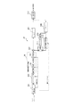
図1は、本発明による一実施例の符号化装置10の概略図である。前述した図16に示す従来からの符号化装置100と同様な構成要素には同一の参照番号を付しており、これらの説明は省略する。
FIG. 1 is a schematic diagram of an
本実施例の符号化装置10は、従来の符号化装置100に対して、DCT及びDSTの選択を画素値レベルでアクティビティを比較して決定する方法(技法1)及びDCT及びDSTの双方の直交変換係数のエネルギー分布を算出して決定する方法(技法2)を適するべく、整数精度変換部105(直交変換部103及び量子化部104)の代わりに、直交変換種別の選択のための制御信号を扱う整数精度変換部15(直交変換部13及び量子化部14)が設けられ、整数精度逆変換部108(逆量子化部106及び逆直交変換部107)の代わりに、直交変換種別の選択のための制御信号を扱う整数精度逆変換部18(逆量子化部16及び逆直交変換部17)が設けられている点で相違する。
The
また、図2は、本発明による一実施例の復号装置30の概略図である。前述した図18に示す従来からの復号装置300と同様な構成要素には同一の参照番号を付しており、これらの説明は省略する。
FIG. 2 is a schematic diagram of a
本実施例の復号装置30は、従来の復号装置300に対して、画素値レベルでアクティビティを比較して決定する方法(技法1)及びDCT及びDSTの双方の直交変換係数のエネルギー分布を算出して決定する方法(技法2)を適するべく、整数精度逆変換部305(逆量子化部303及び逆直交変換部304)の代わりに、直交変換種別の選択のための制御信号を扱う整数精度逆変換部35(逆量子化部33及び逆直交変換部34)が設けられている点で相違する。
The
図3は、DCT及びDSTの選択を画素値レベルでアクティビティを比較して決定する方法(技法1)に対応する整数精度変換部15における直交変換部13の構成を示しており、図4は、DCT及びDSTの双方の直交変換係数のエネルギー分布を算出して決定する方法(技法2)に対応する整数精度変換部15における直交変換部13の構成を示している。
FIG. 3 shows a configuration of the
また、図6は、DCT及びDSTの選択を画素値レベルでアクティビティを比較して決定する方法(技法1)及びDCT及びDSTの双方の直交変換係数のエネルギー分布を算出して決定する方法(技法2)の双方に適用可能な整数精度逆変換部18における逆直交変換部17を示している。
FIG. 6 shows a method of determining DCT and DST selection by comparing activities at the pixel value level (Technique 1) and a method of calculating and determining the energy distribution of orthogonal transform coefficients of both DCT and DST (Technique). 2 shows an inverse
更に、図8は、DCT及びDSTの選択を画素値レベルでアクティビティを比較して決定する方法(技法1)及びDCT及びDSTの双方の直交変換係数のエネルギー分布を算出して決定する方法(技法2)の双方に適用可能な整数精度変換部15における量子化部14の構成を示している。
Further, FIG. 8 shows a method for determining DCT and DST selection by comparing activities at the pixel value level (Technique 1) and a method for calculating and determining the energy distribution of orthogonal transform coefficients of both DCT and DST (Technique 1). 2 shows the configuration of the
更に、図9は、DCT及びDSTの選択を画素値レベルでアクティビティを比較して決定する方法(技法1)及びDCT及びDSTの双方の直交変換係数のエネルギー分布を算出して決定する方法(技法2)の双方に適用可能な整数精度逆変換部35における逆量子化部33の構成を示している。
Further, FIG. 9 shows a method of determining DCT and DST selection by comparing activities at a pixel value level (Technique 1) and a method of calculating and determining energy distribution of both DCT and DST orthogonal transform coefficients (Technique 1). 2 shows the configuration of the
尚、復号装置30における整数精度逆変換部35(逆量子化部33及び逆直交変換部34)は、整数精度逆変換部18(逆量子化部16及び逆直交変換部17)と同様に動作する。
The integer precision inverse transform unit 35 (
以下、具体的にそれぞれのDCT及びDSTの選択を画素値レベルでアクティビティを比較して決定する方法(技法1)及びDCT及びDSTの双方の直交変換係数のエネルギー分布を算出して決定する方法(技法2)について順に説明する。 Hereinafter, specifically, a method of determining the selection of each DCT and DST by comparing activities at the pixel value level (Technique 1) and a method of calculating and determining the energy distribution of orthogonal transform coefficients of both DCT and DST ( Technique 2) will be described in order.
[技法1]
図3(A)を参照するに、DCT及びDSTの選択を画素値レベルでアクティビティを比較して決定する方法(技法1)に対応する直交変換部13は、バッファ131と、切替スイッチ132a及び132bと、DCT133a及びDST133bと、コスト算出部134とを備える。
[Technique 1]
Referring to FIG. 3A, the
DCT133a及びDST133bの処理は、図7に示すような整数精度の変換行列が用いられる。図7は、本発明による一実施例のDCT及びDSTの整数精度の変換行列の例を示している。
The processing of
MPEG−4AVC/H.264では、動き補償予測又は画面内予測の予測画像の信号と、ブロック分割された符号化対象ブロックの画像信号との差分信号に対して、整数精度DCTの直交変換が採用されている。 MPEG-4 AVC / H. In H.264, an orthogonal transform of integer precision DCT is adopted for a difference signal between a prediction image signal of motion compensation prediction or intra prediction and an image signal of an encoding target block that is divided into blocks.
整数精度DCTの変換行列の基底と、整数精度DSTの変換行列の基底は、それぞれn次の基底同士が直交関係にあることが重要である。例えば、整数精度DCTの変換行列では、0次(1行目)が[1 1 1 1]、1次(2行目)が[2 1 −1 −2]、2次(3行目)が[1 −1 −1 1]、3次(4行目)が[1 −2 2 −1]であり、整数精度DSTの変換行列では、1次(1行目)が[1 2 2 1]、2次(2行目)が[1 1 −1 −1]、3次(3行目)が[2 −1 −1 2]、4次(4行目)が[1 −1 1 −1]であるから、整数精度DCTの変換行列の1次の[2 1 −1 −2]と、整数精度DSTの変換行列の1次の[1 2 2 1]が直交関係にある。 It is important that the bases of the integer precision DCT transform matrix and the bases of the integer precision DST transform matrix are orthogonal to each other. For example, in the conversion matrix of integer precision DCT, the 0th order (first line) is [1 1 1 1], the first order (second line) is [2 1 −1 -2], and the second order (third line) is. [1 -1 -1 1], the third order (fourth row) is [1 -2 2 -1], and in the conversion matrix of integer precision DST, the first order (first row) is [1 2 2 1]. The second order (second line) is [1 1 -1 -1], the third order (third line) is [2 -1 -1 2], and the fourth order (fourth line) is [1 -1 1 -1]. ], The first-order [2 1 −1 -2] of the integer precision DCT transformation matrix and the first-order [1 2 2 1] of the integer precision DST transformation matrix are orthogonal to each other.
また、MPEG−4AVC/H.264では、4×4直交変換のほかに、8×8直交変換を用いることもできるが、この場合も同様に、整数精度DCTと整数精度DSTを定義する。MPEG−4AVC/H.264以外の直交変換を用いる場合も、同様に基底ごとに互いに直交関係にある2種類の直交変換の変換行列を規定することができる。 In addition, MPEG-4 AVC / H. In H.264, in addition to 4 × 4 orthogonal transformation, 8 × 8 orthogonal transformation can also be used. In this case as well, integer precision DCT and integer precision DST are defined. MPEG-4 AVC / H. Similarly, when orthogonal transforms other than H.264 are used, two types of orthogonal transformation transform matrices that are orthogonal to each other can be defined for each base.
本実施例では、基底ごとに互いに直交関係にある2種類の直交変換として、DCT(整数精度DCT)及びDST(整数精度DST)を併用するものとして説明するが、基底ごとに互いに直交関係にある2種類の直交変換であれば、同様の効果を得ることができる。 In the present embodiment, two types of orthogonal transforms that are orthogonal to each other are described as being used in combination with DCT (integer precision DCT) and DST (integer precision DST), but each base is orthogonal to each other. Similar effects can be obtained with two types of orthogonal transforms.
図3(A)に示す(技法1)における直交変換部13は、減算部102から供給される差分信号をバッファ131に保持して、コスト算出部134によって、バッファ131から処理対象の差分信号を取り出し、そのアクティビティの値からDCT133a及びDST133bのいずれかを選択するよう制御信号を発生させ、切替スイッチ132a及び132bで切り替えを行うように構成される。
The
図3(B)に示すように、コスト算出部134は、バッファ131から処理対象の差分信号を取り出し、アクティビティの値を算出するアクティビティ算出部1341と、このアクティビティの値と予め定めた閾値と比較してDCT133a及びDST133bのいずれかを選択するよう制御信号を発生する比較部1342とを備える。
As shown in FIG. 3B, the
コスト算出部134は、例えば入力信号(差分信号)の分散値をアクティビティの値として算出して分散値が所定の閾値より大きい場合にのみDSTを選択するか、又は隣接画素間の相関係数をアクティビティの値として算出して相関係数が所定の閾値より小さい場合にのみDSTを選択するように構成される。
For example, the
これにより、簡便な方法として、入力信号(差分信号)を直交変換前に分析していずれの直交変換を用いるかを決定することができ、アクティビティ算出よりも処理コストが大きいDCT133a及びDST133bの並列処理が不要となり、処理コストの低減を図ることができる。
Thus, as a simple method, the input signal (difference signal) can be analyzed before orthogonal transformation to determine which orthogonal transformation is used, and parallel processing of
図8は、本発明による一実施例の量子化部の構成を示す図である。図8を参照するに、整数精度変換部15における量子化部14は、正規化係数マトリクス記憶部1411と、マトリクス読出制御部1412と、量子化ステップ算出部1413と、量子化演算部1414とを備える。量子化部14の各構成は、MPEG−4AVC/H.264で採用されている処理構成とほぼ同様であるが、DCT133a及びDST133bの各々用の正規化係数マトリクスを正規化係数マトリクス記憶部1411に記憶しておき、マトリクス読出制御部1412が、直交変換部13からの直交変換種別の選択のための制御信号に従って各直交変換に対応する正規化係数マトリクスを読み出すように構成している点で相違する。尚、この制御信号は、ヘッダ情報として付加される場合には、入力される処理対象の信号から抽出する。
FIG. 8 is a diagram illustrating a configuration of a quantization unit according to an embodiment of the present invention. Referring to FIG. 8, the
量子化ステップ算出部1413は、逆量子化でも共通に用いる予め定めた量子化パラメータqPに従う量子化係数を正規化係数マトリクスから読み出して量子化ステップを算出し、量子化演算部1414が、入力される直交変換係数の信号を、算出した量子化ステップで除算して量子化ブロックの量子化信号を生成して外部に送出する。
The quantization step calculation unit 1413 reads a quantization coefficient according to a predetermined quantization parameter qP that is also commonly used in inverse quantization from the normalized coefficient matrix, calculates a quantization step, and the
正規化係数マトリクスの例、及び量子化係数の例を、それぞれ図10及び図11に示す。この場合の量子化ステップは、量子化パラメータqPを6で除算した剰余(0〜5の値)で定まる要素位置ごとの値(α,β,γごとの値)に対して当該除算した商でビット左シフトさせて得られる値に相当する(MPEG−4AVC/H.264の方式と同様)。 An example of the normalization coefficient matrix and an example of the quantization coefficient are shown in FIGS. 10 and 11, respectively. The quantization step in this case is a quotient obtained by dividing the value for each element position (value for each α, β, γ) determined by the remainder (value of 0 to 5) obtained by dividing the quantization parameter qP by 6. It corresponds to a value obtained by shifting the bit left (similar to the MPEG-4 AVC / H.264 system).
このように、(技法1)によれば、処理コストを低減させつつ、最適な直交変換係数を判断して符号化することができる。 As described above, according to (Technique 1), it is possible to determine and code the optimal orthogonal transform coefficient while reducing the processing cost.
尚、符号化装置10の局部復号の整数精度逆変換部18(逆量子化部16及び逆直交変換部17)の動作は、図6及び図9に示すように簡単な構成で処理コストを増大させることなく実現することができる。
The operation of the integer precision inverse transform unit 18 (
図9は、本発明による一実施例の逆量子化部の構成を示す図である。図9を参照するに、整数精度逆変換部18における逆量子化部16は、正規化係数マトリクス記憶部1611と、マトリクス読出制御部1612と、量子化ステップ算出部1613と、逆量子化演算部1614とを備える。逆量子化部18の各構成は、MPEG−4AVC/H.264で採用されている処理構成とほぼ同様であるが、DCT133a及びDST133bの各々用の正規化係数マトリクスを正規化係数マトリクス記憶部1611に記憶しておき、マトリクス読出制御部1612が、直交変換部13からの直交変換種別の選択のための制御信号に従って各直交変換に対応する正規化係数マトリクスを読み出すように構成している点で相違する。尚、この制御信号は、ヘッダ情報として付加される場合には、入力される処理対象の信号から抽出する。
FIG. 9 is a diagram illustrating a configuration of an inverse quantization unit according to an embodiment of the present invention. Referring to FIG. 9, the
量子化ステップ算出部1613は、量子化でも共通に用いる予め定めた量子化パラメータqPに従う量子化係数を正規化係数マトリクスから読み出して量子化ステップを算出し、量子化演算部1614が、入力される量子化ブロックの量子化信号を、算出した量子化ステップで乗算して直交変換係数の信号を生成して外部に送出する。
The quantization
図6に示す逆直交変換部17は、直交変換部13からの制御信号に従って、逆量子化部16から供給される対応する逆直交変換のIDCT171a又はIDST171bのいずれかを選択する切替スイッチ172a及び172bで切り替えを行って、適応的に差分信号を復元する。
The inverse
整数精度逆変換部18(逆量子化部16及び逆直交変換部17)の動作は、復号装置30における整数精度逆変換部35(逆量子化部33及び逆直交変換部34)の動作も同様である。
The operations of the integer precision inverse transform unit 18 (the
従って、(技法1)によれば、処理コストを低減させつつ、最適な直交変換係数を判断して符号化することができる。 Therefore, according to (Technique 1), it is possible to determine and code the optimum orthogonal transform coefficient while reducing the processing cost.
次に、DCT及びDSTの双方の直交変換係数のエネルギー分布を算出して決定する方法(技法2)について説明する。 Next, a method (Technique 2) for calculating and determining the energy distribution of orthogonal transform coefficients of both DCT and DST will be described.
[技法2]
図4(A)を参照するに、DCT及びDSTの双方の直交変換係数のエネルギー分布を算出して決定する方法(技法2)に対応する直交変換部13は、DCT133a及びDST133bと、バッファ134a,134bと、切替スイッチ135と、コスト算出部136とを備える。
[Technique 2]
Referring to FIG. 4A, the
図4(A)に示す(技法3)における直交変換部13は、減算部102から供給される差分信号をDCT133a及びDST133bにてそれぞれ直交変換を施し、それぞれバッファ134a,134bに格納するとともに、コスト算出部136によって、DCT133a及びDST133bの双方の直交変換係数のエネルギー分布からDCT133a及びDST133bのいずれかを選択するよう制御信号を発生させ、切替スイッチ135でそれぞれのバッファ134a,134bからの読出しを制御して切替を行うように構成される。
The
図4(B)に示すように、コスト算出部136は、DCT133aのマクロブロックにおける直交変換係数のエネルギー分布を算出してエネルギー集中度を算出するマクロブロックエネルギー集中度算出部1361と、DST133bのマクロブロックにおける直交変換係数のエネルギー分布を算出してエネルギー集中度を算出するマクロブロックエネルギー集中度算出部1362と、マクロブロックエネルギー集中度算出部1361,1362の各々で算出したエネルギー集中度を比較して、エネルギー集中度の高いほうのDCT133a及びDST133bのいずれかを選択するよう制御信号を発生する比較部1363とを備える。
As shown in FIG. 4B, the
尚、整数精度変換部15における量子化部14の構成は前述の図8の説明と同様であり、符号化装置10の局部復号の整数精度逆変換部18(逆量子化部16及び逆直交変換部17)の動作や復号装置30における整数精度逆変換部35(逆量子化部33及び逆直交変換部34)の動作も、前述の図6及び図9の説明と同様である。
Note that the configuration of the
これにより、(技法2)によれば、(技法1)と比較してDCT133a及びDST133bの並列処理が必要ではあるが、実際に処理した直交変換係数の値からそのエネルギー集中度を比較するため、(技法1)と比較して符号化効率が改善する。
As a result, according to (Technique 2), parallel processing of
尚、(技法2)の変形例として、DCT及びDSTの選択を画素値レベルでアクティビティを比較して決定する代わりに、DCT133a及び量子化部からなる信号系統と、DST133b及び量子化部からなる信号系統の出力からマクロブロックにおけるエネルギー分布を算出してエネルギー集中度を算出してエネルギー集中度の高いほうの信号系統を選択するよう制御信号を発生するよう整数精度変換部15を構成することもできる(図示せず)。
As a modified example of (Technique 2), instead of determining the selection of DCT and DST by comparing activities at the pixel value level, a signal
上述した(技法1)及び(技法2)では、従来からのMPEG−4AVC/H.264の方式の符号化装置300に対して、整数精度変換部15及び整数精度逆変換部18,35を組み替えるのみで、最適な直交変換係数を判断して符号化することができる。一方で、更に符号化効率を向上させたい場合に、DCT及びDSTの双方の直交変換係数の量子化及びエントロピー符号化による符号量を算出し、その際のレート歪み最適化法に基づくコスト値を比較して効率の良いほうを選択する方法(技法3)があり、以下、説明する。
In the above (Technique 1) and (Technique 2), the conventional MPEG-4 AVC / H. Only the integer
図5は、DCT及びDSTの双方の直交変換係数の量子化及びエントロピー符号化による符号量を算出し、その際のレート歪み最適化法に基づくコスト値を比較して効率の良いほうを選択する方法(技法3)に対応する構成を示している。図5(A)に示すように、DCT及びDSTの双方の直交変換係数の量子化及びエントロピー符号化による符号量を算出するよう構成されたコスト算出処理ユニット19は、DCT133a及びDST133bと、量子化部137a,137bと、エントロピー符号化部138a,138bと、バッファ139a,139bと、切替スイッチ140と、コスト算出部141とを備える。
FIG. 5 calculates the amount of code by quantization and entropy coding of orthogonal transform coefficients of both DCT and DST, and compares the cost values based on the rate distortion optimization method at that time to select the more efficient one The structure corresponding to the method (Technique 3) is shown. As shown in FIG. 5A, the cost
コスト算出処理ユニット19は、減算部102から供給される差分信号をDCT133a及びDST133bにてそれぞれ直交変換を施し、さらに量子化部137a,137bによって、それぞれの直交変換ごとに量子化を施し、さらにエントロピー符号化部138a,138bによってそれぞれの量子化ブロックの量子化信号ごとにエントロピー符号化を施し、各符号化したビットストリーム信号(符号化値)をそれぞれバッファ139a,139bに格納するとともに、コスト算出部141によって、DCT133a及びDST133bの双方の信号系統における符号量からDCT133a及びDST133bの信号系統のいずれかを選択するよう制御信号を発生させ、切替スイッチ135でそれぞれのバッファ139a,139bからの読出しを制御して切り替えを行うように構成される。
The cost
図5(B)に示すように、コスト算出部141は、DCT係数に基づく符号化値から歪み量を算出する歪み量算出部1421と、DST係数に基づく符号化値から歪み量を算出する歪み量算出部1422と、レート歪み最適化法に基づくコスト値を比較して効率の良いほうを選択する比較部1423とを備える。
As shown in FIG. 5B, the
これにより、(技法3)によれば、(技法1)及び(技法2)と比較してDCT133a及びDST133bからの各信号系統の並列処理が必要ではあるが、実際に処理した直交変換係数の値からその符号化コストと品質の効率によって比較するため、(技法1)及び(技法2)と比較して符号化効率が改善する。
Thus, according to (Technique 3), the parallel processing of each signal system from
尚、当業者であれば、コスト算出処理ユニット19を、前述した符号化装置10(又は復号装置30)に適用可能であることは上記の説明から理解される。
A person skilled in the art understands that the cost
上記の説明では、4×4ブロックの符号化処理についてコスト計算して最適な直交変換(又は直交変換の信号系統)を選択する例について説明したが、MPEG−4AVC/H.264の方式では、8×8ブロックの符号化処理もサポートされている。従って、本実施例の符号化装置10において、4×4ブロックと8×8ブロックの双方の符号化処理についてコスト計算して最適な直交変換(又は直交変換の信号系統)を選択するように構成することもできる。
In the above description, an example in which the cost is calculated for the encoding process of 4 × 4 blocks and the optimum orthogonal transform (or signal system of the orthogonal transform) is selected has been described, but MPEG-4 AVC / H. In the H.264 system, 8 × 8 block encoding processing is also supported. Therefore, the
最も好適なコスト算出において、符号化対象ブロックに対して異なる画素ブロックサイズごとの差分信号についてそれぞれコスト計算を行って、最も少ない符号量となる画素ブロックサイズ及び直交変換処理の組み合わせを決定し、符号化対象ブロックの差分信号に対する最適な直交変換(又は直交変換の信号系統)を選択するように切り替えを制御することである。つまり、4×4ブロックと8×8ブロックの双方の符号化処理についてコスト計算することは、前述したいずれの例でも適用可能である。 In the most preferable cost calculation, the cost calculation is performed for each difference signal for different pixel block sizes with respect to the encoding target block, and the combination of the pixel block size and the orthogonal transformation process that provides the smallest code amount is determined. The switching is controlled so as to select the optimal orthogonal transform (or signal system of the orthogonal transform) for the difference signal of the conversion target block. That is, the cost calculation for both the 4 × 4 block and the 8 × 8 block encoding processes can be applied to any of the examples described above.
例えば、ブロック化部101によって、16×16画素マクロブロックから、8×8画素(8×8ブロック)に分割し、さらに、4×4画素(4×4ブロック)に再分割する例を考える。この場合、8×8ブロックで、直交変換(又は直交変換の信号系統)のコスト計算を行うとともに、4×4ブロックで、直交変換(又は直交変換の信号系統)のコスト計算を行う。続いて、例えばレート歪み最適化法に基づいて算出した全てのコスト値から最小のものを選択し、符号化ビットストリームを最終決定する。
For example, consider an example in which the
上記の例では、DCTベースの符号化方式ではエネルギー集中度が十分でないような画像信号に対しても、ブロック内の画素間相関の強さに適切に応じた直交変換係数を判断して符号化する符号化装置10、この符号化した信号を復号する復号装置30が実現される。ただし、MPEG−4AVC/H.264では、演算負担を軽減させることを意図して、整数精度DCTと量子化を一括処理するように規定されており、単にDCTとDSTの双方で直交変換を施すように構成することは現在における映像符号化の趣旨にも反することになりかねない。そこで、DCTとDSTの双方で直交変換を施すとしても如何にして演算負担を軽減させるかについて以下説明する。
In the above example, even for an image signal whose energy concentration is not sufficient in the DCT-based encoding method, encoding is performed by determining an orthogonal transform coefficient appropriately corresponding to the strength of inter-pixel correlation in the block. And the
通常、MPEG−4AVC/H.264の方式のままでDCTとDSTを併用すると、正規化係数マトリクス(量子化演算に用いるMF:Multiplication Factorのマトリクス)として、各直交変換に固有の量子化係数からなるものを用意する必要があり、DCTとDSTでは個別の正規化係数マトリクスを用いることになる。このような正規化係数マトリクスは符号化装置及び復号装置でメモリに保持し続ける必要があり、2種類の直交変換を採用する場合、量子化のためのメモリ量が2倍になるという問題が生じる。 Usually, MPEG-4 AVC / H. When DCT and DST are used together in the H.264 format, it is necessary to prepare a normalization coefficient matrix (MF: matrix used for quantization operation) consisting of quantization coefficients specific to each orthogonal transform. In DCT and DST, separate normalization coefficient matrices are used. Such a normalization coefficient matrix needs to be kept in the memory by the encoding device and the decoding device. When two types of orthogonal transformation are adopted, there is a problem that the amount of memory for quantization is doubled. .
しかしながら、図10から明らかなように、整数精度DCTと整数精度DSTでは、正規化係数マトリクスの配置が、右下方向に(1,1)ずらした関係にあり、各々の係数値が一致する。 However, as is apparent from FIG. 10, in the integer precision DCT and the integer precision DST, the arrangement of the normalized coefficient matrix is shifted by (1, 1) in the lower right direction, and the coefficient values thereof match.
そこで、マトリクス読出制御部1412,1612(図8及び図9)によって、DCTの正規化係数マトリクスのみを正規化係数マトリクス記憶部1411,1611(図8及び図9)に格納しておき、マトリクス読出制御部1412,1612(図8及び図9)によって、DCTとDSTで正規化係数マトリクスの読み出し順を切替えることで、DCTとDSTで同一の正規化係数マトリクスからそれぞれの量子化係数の値を用いることができるようになり、メモリ量の増大の問題を解決することができる(図12参照)。
Therefore, the matrix read
更に、別の方法として、正規化係数マトリクスの読み出し順を切替える代わりに、マトリクス読出制御部1412,1612(図8及び図9)によって、DCTの正規化係数マトリクスのみを正規化係数マトリクス記憶部1411,1611(図8及び図9)に格納しておき、DSTの変換行列を図13及び図14に示すごとく変形し、DCT及びDSTにおける互いの変換行列が、DCT及びDSTの切り替えに応じて切り替えられるスキャニングオーダーに対応して当該共通の正規化係数マトリクスを用いて量子化することができる直交関係で規定する。これにより、スキャニング部125によって当該直交変換の切り替えを表す制御信号に従って、量子化後の伝送すべき係数を1次元配列に変換する際のスキャニングオーダーをDCT(図15)とDST(図16)で切替えることで、DCTとDSTで同一の正規化係数マトリクスからそれぞれの量子化係数の値を用いることができるようになり、メモリ量の増大の問題を解決することができる。
Furthermore, as another method, instead of switching the reading order of the normalization coefficient matrix, only the normalization coefficient
即ち、DSTの変換行列を変形して直交変換を施し、DCTと同一の正規化係数マトリクスを用いると、DSTの最低次数が(0,0)の位置でなく、(1,1)に配置されるため、量子化後の伝送すべき係数を1次元配列に変換する際のスキャニングオーダーを(1,1)から開始するようにする。 That is, when the transformation matrix of DST is transformed and orthogonal transformation is performed, and the same normalization coefficient matrix as DCT is used, the lowest order of DST is placed at (1, 1) instead of (0, 0). Therefore, the scanning order for converting the coefficient to be transmitted after quantization into a one-dimensional array is started from (1, 1).
符号化装置10における局部復号時や、復号装置30における逆量子化を行う場合も同様に、DCT及びDSTのいずれを選択したかを表す制御信号を取得して、符号化された当該フレーム画像を復号する際に、符号化された当該フレーム画像における量子化信号に対して、DCT及びDSTに共通する正規化係数マトリクスを用いて逆量子化処理を施すように構成する。
Similarly, when local decoding is performed in the
また、MPEG−4AVC/H.264では、画面内予測時に、例えば4×4ブロック(輝度信号)及び2×2ブロック(色差信号)のDCTの直交変換係数の直流成分に対しては、1つの直流成分の画素ブロックを構成してアダマール変換を実行することで空間周波数分解能を改善する技術があるが、本発明に係るDSTの最低次数の成分に対して同様にアダマール変換を実行するよう構成することもできる。 In addition, MPEG-4 AVC / H. In H.264, a pixel block of one DC component is configured for DC components of DCT orthogonal transform coefficients of, for example, 4 × 4 blocks (luminance signals) and 2 × 2 blocks (color difference signals) during intra prediction. Although there is a technique for improving the spatial frequency resolution by executing the Hadamard transform, the Hadamard transform can be similarly performed on the lowest-order component of the DST according to the present invention.
これにより、演算負担をさほど増大させることなく、DCTベースの符号化方式ではエネルギー集中度が十分でないような画像信号に対しても、ブロック内の画素間相関の強さに適切に応じた直交変換係数を判断して符号化する符号化装置、及び、この符号化した信号を復号する復号装置を実現することができる。 This makes it possible to perform orthogonal transformation in accordance with the strength of inter-pixel correlation within a block, even for image signals whose energy concentration is not sufficient in the DCT-based coding method without increasing the computational burden. An encoding device that determines and encodes a coefficient, and a decoding device that decodes the encoded signal can be realized.
更に、本発明の一態様として、符号化装置10及び復号装置30をコンピュータとして構成させることができる。コンピュータに、前述した符号化装置10及び復号装置30の各構成要素を実現させるためのプログラムは、コンピュータの内部又は外部に備えられる記憶部に記憶される。そのような記憶部は、外付けハードディスクなどの外部記憶装置、或いはROM又はRAMなどの内部記憶装置で実現することができる。コンピュータに備えられる制御部は、中央演算処理装置(CPU)などの制御で実現することができる。即ち、CPUが、各構成要素の機能を実現するための処理内容が記述されたプログラムを、適宜、記憶部から読み込んで、各構成要素の機能をコンピュータ上で実現させることができる。ここで、各構成要素の機能をハードウェアの一部で実現しても良い。
Furthermore, as one aspect of the present invention, the
また、この処理内容を記述したプログラムを、例えばDVD又はCD−ROMなどの可搬型記録媒体の販売、譲渡、貸与等により流通させることができるほか、そのようなプログラムを、例えばネットワーク上にあるサーバの記憶部に記憶しておき、ネットワークを介してサーバから他のコンピュータにそのプログラムを転送することにより、流通させることができる。 In addition, the program describing the processing contents can be distributed by selling, transferring, or lending a portable recording medium such as a DVD or CD-ROM, and such a program can be distributed on a server on a network, for example. Can be distributed by transferring the program from the server to another computer via the network.
また、そのようなプログラムを実行するコンピュータは、例えば、可搬型記録媒体に記録されたプログラム又はサーバから転送されたプログラムを、一旦、自己の記憶部に記憶することができる。また、このプログラムの別の実施態様として、コンピュータが可搬型記録媒体から直接プログラムを読み取り、そのプログラムに従った処理を実行することとしてもよく、更に、このコンピュータにサーバからプログラムが転送される度に、逐次、受け取ったプログラムに従った処理を実行することとしてもよい。 In addition, a computer that executes such a program can temporarily store, for example, a program recorded on a portable recording medium or a program transferred from a server in its own storage unit. As another embodiment of the program, the computer may directly read the program from a portable recording medium and execute processing according to the program, and each time the program is transferred from the server to the computer. In addition, the processing according to the received program may be executed sequentially.
以上、具体例を挙げて本発明の実施例を詳細に説明したが、本発明の特許請求の範囲から逸脱しない限りにおいて、あらゆる変形や変更が可能であることは当業者に明らかである。特に、正規化部における正規化処理は、教師信号による修正処理における信号間の相関をとるためのレベル調整を行うものであればよい。 While the embodiments of the present invention have been described in detail with specific examples, it will be apparent to those skilled in the art that various modifications and changes can be made without departing from the scope of the claims of the present invention. In particular, the normalization process in the normalization unit only needs to perform level adjustment for correlation between signals in the correction process using the teacher signal.
本発明によれば、DCTベースの符号化方式ではエネルギー集中度が十分でないような画像信号に対しても、最適な直交変換係数を判断して符号化することが可能となるので、映像符号化技術に有用である。 According to the present invention, it is possible to determine and code an optimal orthogonal transform coefficient even for an image signal whose energy concentration is not sufficient in the DCT-based encoding method. Useful for technology.
10 符号化装置
13 直交変換部
14 量子化部
15 整数精度変換部
16 逆量子化部
17 逆直交変換部
18 整数精度逆変換部
19 コスト算出処理ユニット
30 復号装置
33 逆量子化部
34 逆直交変換部
35 整数精度逆変換部
100 符号化装置
101 ブロック化部
102 減算部
103 直交変換部
104 量子化部
105 整数精度変換部
106 逆量子化部
107 逆直交変換部
108 整数精度逆変換部
109 加算部
120 デブロッキングフィルタ
121 メモリ
122 フレーム内予測部
123 動き補償予測部
124 切替スイッチ
125 スキャニング部
126 エントロピー符号化部
131 バッファ
134 コスト算出部
134a,134b バッファ
135 切替スイッチ
136 コスト算出部
137a,137b 量子化部
138a,138b エントロピー符号化部
139a,139b バッファ
140 切替スイッチ
141 コスト算出部
171a 整数精度IDCT
171b 整数精度IDST
172a,172b 切替スイッチ
300 復号装置
301 エントロピー復号部
302 スキャニング部
303 逆量子化部
304 逆直交変換部
305 整数精度逆変換部
306 加算部
307 デブロッキングフィルタ
308 メモリ
309 フレーム内予測部
310 動き補償予測部
311 切替スイッチ
312 並べ替え部
1031a 整数精度DCT
1031b 整数精度DST
1032 0ランレングス比較部
1033 切替スイッチ
1341 アクティビティ算出部
1361,1362 マクロブロックエネルギー集中度算出部
1363 比較部
1411 正規化係数マトリクス記憶部
1412 マトリクス読出制御部
1413 量子化ステップ算出部
1414 量子化演算部
1421,1422 歪み量算出部
1423 比較部
1611 正規化係数マトリクス記憶部
1612 マトリクス読出制御部
1613 量子化ステップ算出部
1614 逆量子化演算部
DESCRIPTION OF
171b Integer precision IDST
172a, 172b
1031b integer precision DST
1032 0-run
Claims (8)
第1整数変換処理及び前記第1整数変換処理とは異なる第2整数変換処理の中から選択された整数変換処理を前記差分信号に適用して、前記差分信号の整数変換処理を行う整数変換処理部と、
前記第1整数変換処理が適用される前記差分信号及び前記第2整数変換処理が適用される前記差分信号に共通する正規化係数マトリクスを用いて、前記整数変換処理部によって前記整数変換処理が施された前記差分信号の量子化を行う量子化部とを備えることを特徴とする符号化装置。 A difference signal between the encoding target block and the prediction image is generated based on the encoding target block obtained by dividing the frame image and the prediction image generated for the encoding target block. And an encoding device for encoding the difference signal ,
An integer conversion process for applying an integer conversion process selected from a first integer conversion process and a second integer conversion process different from the first integer conversion process to the difference signal and performing an integer conversion process on the difference signal And
Using the normalization coefficient matrix common to the difference signal to which the first integer conversion process is applied and the difference signal to which the second integer conversion process is applied, the integer conversion processing unit performs the integer conversion process. And a quantizing unit that quantizes the difference signal .
前記フレーム画像の符号化は、前記フレーム画像を分割することによって得られる符号化対象ブロックと前記符号化対象ブロックに対して生成される予測画像とに基づいて、前記符号化対象ブロックと前記予測画像との間における差分信号を生成するとともに、前記差分信号の符号化を行う手順を含み、 The encoding of the frame image is performed based on the encoding target block obtained by dividing the frame image and the prediction image generated for the encoding target block, and the prediction image. Including a procedure for generating a difference signal between and encoding the difference signal,
前記差分信号の逆量子化を行う逆量子化部と、 An inverse quantization unit that performs inverse quantization of the differential signal;
第1逆整数変換処理及び前記第1逆整数変換処理とは異なる第2逆整数変換処理の中から選択された逆整数変換処理を、前記逆量子化部によって前記逆量子化が施された前記差分信号に適用して、前記差分信号の逆整数変換処理を行う逆整数変換処理部とを備え、 The inverse integer transform process selected from the first inverse integer transform process and the second inverse integer transform process different from the first inverse integer transform process is subjected to the inverse quantization by the inverse quantization unit. An inverse integer conversion processing unit that applies the difference signal and performs an inverse integer conversion process on the difference signal;
前記逆量子化部は、前記第1逆整数変換処理が適用される前記差分信号及び前記第2逆整数変換処理が適用される前記差分信号に共通する正規化係数マトリクスを用いて、前記差分信号の逆量子化を行うことを特徴とする復号装置。 The inverse quantization unit uses the normalization coefficient matrix common to the difference signal to which the first inverse integer transform process is applied and the difference signal to which the second inverse integer transform process is applied, to use the difference signal. The decoding apparatus characterized by performing inverse quantization of.
Priority Applications (1)
| Application Number | Priority Date | Filing Date | Title |
|---|---|---|---|
| JP2010086549A JP5377395B2 (en) | 2010-04-02 | 2010-04-02 | Encoding device, decoding device, and program |
Applications Claiming Priority (1)
| Application Number | Priority Date | Filing Date | Title |
|---|---|---|---|
| JP2010086549A JP5377395B2 (en) | 2010-04-02 | 2010-04-02 | Encoding device, decoding device, and program |
Publications (3)
| Publication Number | Publication Date |
|---|---|
| JP2011223068A JP2011223068A (en) | 2011-11-04 |
| JP2011223068A5 JP2011223068A5 (en) | 2013-05-23 |
| JP5377395B2 true JP5377395B2 (en) | 2013-12-25 |
Family
ID=45039531
Family Applications (1)
| Application Number | Title | Priority Date | Filing Date |
|---|---|---|---|
| JP2010086549A Active JP5377395B2 (en) | 2010-04-02 | 2010-04-02 | Encoding device, decoding device, and program |
Country Status (1)
| Country | Link |
|---|---|
| JP (1) | JP5377395B2 (en) |
Families Citing this family (8)
| Publication number | Priority date | Publication date | Assignee | Title |
|---|---|---|---|---|
| US9172968B2 (en) | 2010-07-09 | 2015-10-27 | Qualcomm Incorporated | Video coding using directional transforms |
| US10992958B2 (en) | 2010-12-29 | 2021-04-27 | Qualcomm Incorporated | Video coding using mapped transforms and scanning modes |
| CN104322064A (en) | 2012-04-16 | 2015-01-28 | 韩国电子通信研究院 | Encoding method and decoding method, and device using same |
| CN112969073A (en) * | 2012-07-02 | 2021-06-15 | 韩国电子通信研究院 | Image encoding/decoding method and non-transitory computer-readable recording medium |
| US9319684B2 (en) * | 2012-08-21 | 2016-04-19 | Qualcomm Incorporated | Alternative transform in scalable video coding |
| WO2014120368A1 (en) | 2013-01-30 | 2014-08-07 | Intel Corporation | Content adaptive entropy coding for next generation video |
| JP6159139B2 (en) * | 2013-05-07 | 2017-07-05 | 日本放送協会 | Image processing apparatus, encoding apparatus, and program |
| CN116886913B (en) * | 2023-08-03 | 2024-03-08 | 镕铭微电子(济南)有限公司 | Rate distortion optimization quantization method, device, electronic equipment and storage medium |
Family Cites Families (5)
| Publication number | Priority date | Publication date | Assignee | Title |
|---|---|---|---|---|
| JPH02200082A (en) * | 1989-01-30 | 1990-08-08 | Hitachi Ltd | Image encoder |
| JPH0522715A (en) * | 1991-07-12 | 1993-01-29 | Sony Corp | Picture encoder |
| JPH10285595A (en) * | 1997-04-08 | 1998-10-23 | Matsushita Joho Syst Kk | Image data transmitter-receiver |
| JP2900998B2 (en) * | 1997-07-31 | 1999-06-02 | 日本ビクター株式会社 | Block interpolation predictive encoding apparatus, decoding apparatus, encoding method and decoding method |
| JP4825227B2 (en) * | 2008-02-04 | 2011-11-30 | 日本放送協会 | Image decoding apparatus and image processing program |
-
2010
- 2010-04-02 JP JP2010086549A patent/JP5377395B2/en active Active
Also Published As
| Publication number | Publication date |
|---|---|
| JP2011223068A (en) | 2011-11-04 |
Similar Documents
| Publication | Publication Date | Title |
|---|---|---|
| RU2713610C1 (en) | Improved intraframe prediction encoding using planar views | |
| JP5377395B2 (en) | Encoding device, decoding device, and program | |
| JP7445799B2 (en) | Image decoding device and image decoding method | |
| DK3282705T3 (en) | PROCEDURE FOR DECODING AND APPARATUS FOR ENCODING A PICTURE THROUGH INTRAPHIC PREDICTION. | |
| JP2023179682A (en) | Intra prediction using linear or affine transformation with adjacent sample reduction | |
| JP5215951B2 (en) | Encoding apparatus, control method therefor, and computer program | |
| US20140233646A1 (en) | Methods, apparatuses, and programs for encoding and decoding picture | |
| KR101615643B1 (en) | Compression of pictures | |
| KR20120030537A (en) | Image encoding device, image decoding device, image encoding method, and image decoding method | |
| JP2011188368A (en) | Encoding apparatus, decoding apparatus and program | |
| JP5613319B2 (en) | Video encoding apparatus, video encoding method, and video encoding program | |
| JP2011166592A (en) | Image encoding device, and image decoding device | |
| JP5302256B2 (en) | Encoding device, decoding device, and program | |
| JP6360214B2 (en) | Video decoding method | |
| JP2021027464A (en) | Prediction block generation device, image coding device, image decoding device, and program | |
| KR20210089778A (en) | Video stream adaptive filtering to reduce bitrate | |
| JP5174062B2 (en) | Intra prediction apparatus, encoder, decoder, and program | |
| WO2015045301A1 (en) | Video encoding device, video encoding method, and video encoding program | |
| JP5358485B2 (en) | Image encoding device | |
| JP2007266861A (en) | Image encoding device | |
| CN114007080B (en) | Encoding and decoding method, device and equipment | |
| JP2006074520A (en) | Motion vector detecting device | |
| JP5298082B2 (en) | Encoding apparatus and decoding apparatus for adaptively determining scan order of orthogonal transform coefficients | |
| WO2014076165A1 (en) | Method, computer program and system for determining skip mode |
Legal Events
| Date | Code | Title | Description |
|---|---|---|---|
| RD02 | Notification of acceptance of power of attorney |
Free format text: JAPANESE INTERMEDIATE CODE: A7422 Effective date: 20130201 |
|
| RD04 | Notification of resignation of power of attorney |
Free format text: JAPANESE INTERMEDIATE CODE: A7424 Effective date: 20130207 |
|
| RD04 | Notification of resignation of power of attorney |
Free format text: JAPANESE INTERMEDIATE CODE: A7424 Effective date: 20130208 |
|
| A521 | Request for written amendment filed |
Free format text: JAPANESE INTERMEDIATE CODE: A523 Effective date: 20130218 |
|
| A621 | Written request for application examination |
Free format text: JAPANESE INTERMEDIATE CODE: A621 Effective date: 20130401 |
|
| A521 | Request for written amendment filed |
Free format text: JAPANESE INTERMEDIATE CODE: A523 Effective date: 20130405 |
|
| A871 | Explanation of circumstances concerning accelerated examination |
Free format text: JAPANESE INTERMEDIATE CODE: A871 Effective date: 20130405 |
|
| A975 | Report on accelerated examination |
Free format text: JAPANESE INTERMEDIATE CODE: A971005 Effective date: 20130422 |
|
| A131 | Notification of reasons for refusal |
Free format text: JAPANESE INTERMEDIATE CODE: A131 Effective date: 20130611 |
|
| TRDD | Decision of grant or rejection written | ||
| A01 | Written decision to grant a patent or to grant a registration (utility model) |
Free format text: JAPANESE INTERMEDIATE CODE: A01 Effective date: 20130827 |
|
| A61 | First payment of annual fees (during grant procedure) |
Free format text: JAPANESE INTERMEDIATE CODE: A61 Effective date: 20130924 |
|
| R150 | Certificate of patent or registration of utility model |
Ref document number: 5377395 Country of ref document: JP Free format text: JAPANESE INTERMEDIATE CODE: R150 Free format text: JAPANESE INTERMEDIATE CODE: R150 |
|
| R250 | Receipt of annual fees |
Free format text: JAPANESE INTERMEDIATE CODE: R250 |
|
| R250 | Receipt of annual fees |
Free format text: JAPANESE INTERMEDIATE CODE: R250 |
|
| R250 | Receipt of annual fees |
Free format text: JAPANESE INTERMEDIATE CODE: R250 |
|
| R250 | Receipt of annual fees |
Free format text: JAPANESE INTERMEDIATE CODE: R250 |
|
| R250 | Receipt of annual fees |
Free format text: JAPANESE INTERMEDIATE CODE: R250 |
|
| R250 | Receipt of annual fees |
Free format text: JAPANESE INTERMEDIATE CODE: R250 |
|
| R250 | Receipt of annual fees |
Free format text: JAPANESE INTERMEDIATE CODE: R250 |
|
| R250 | Receipt of annual fees |
Free format text: JAPANESE INTERMEDIATE CODE: R250 |
|
| R250 | Receipt of annual fees |
Free format text: JAPANESE INTERMEDIATE CODE: R250 |