JP5377097B2 - Projection display device and light source device - Google Patents
Projection display device and light source device Download PDFInfo
- Publication number
- JP5377097B2 JP5377097B2 JP2009140870A JP2009140870A JP5377097B2 JP 5377097 B2 JP5377097 B2 JP 5377097B2 JP 2009140870 A JP2009140870 A JP 2009140870A JP 2009140870 A JP2009140870 A JP 2009140870A JP 5377097 B2 JP5377097 B2 JP 5377097B2
- Authority
- JP
- Japan
- Prior art keywords
- light
- light source
- optical axis
- light beam
- incident
- Prior art date
- Legal status (The legal status is an assumption and is not a legal conclusion. Google has not performed a legal analysis and makes no representation as to the accuracy of the status listed.)
- Expired - Fee Related
Links
Images


Abstract
Description
本発明は、複数の光源ランプを用いた投写型表示装置に関する。 The present invention relates to a projection display device using a plurality of light source lamps.
投写型表示装置の分野では、表示映像の大画面化及び高輝度化を実現するために、複数の光源ランプを備えた(多灯式の)光源装置を備えたものが提案されている。このような光源装置としては、例えば、2つの光源ランプを対向させて配置し、両光源ランプの集光点近傍にプリズムを配置し、両光源ランプから出射した光をプリズムで合成するようにした光源装置が提案されている(例えば、特許文献1参照)。 In the field of the projection display device, in order to realize a large screen and high brightness of a display image, a device having a (multi-lamp) light source device including a plurality of light source lamps has been proposed. As such a light source device, for example, two light source lamps are arranged to face each other, a prism is arranged in the vicinity of a condensing point of both light source lamps, and light emitted from both light source lamps is synthesized by the prism. A light source device has been proposed (see, for example, Patent Document 1).
しかしながら、上述したような2つの光源ランプがプリズムを挟んで対向配置された構成では、光源ランプから出射された光のうち、プリズムに入射しない光の割合が高く、光利用効率が低下するという問題がある。また、プリズムに入射しなかった光(ロス光)が対向する光源ランプの発光部に到達することにより、光源ランプの温度が上昇し、光源ランプの寿命が短くなるという問題がある。 However, in the configuration in which the two light source lamps are arranged to face each other with the prism interposed therebetween, the ratio of the light not incident on the prism out of the light emitted from the light source lamp is high, and the light use efficiency decreases. There is. In addition, when light (loss light) that has not entered the prism reaches the light-emitting portion of the facing light source lamp, there is a problem that the temperature of the light source lamp rises and the life of the light source lamp is shortened.
そこで、2つの光源ランプを、それぞれの光軸が略直交するように配置し、一方の光源ランプをインテグレータロッドの入射端にほぼ対向させると共に、他方の光源ランプから出射された光の光路をミラーにより折り曲げてインテグレータロッドに向かわせるようにした光源装置が提案されている(例えば、特許文献2参照)。 Therefore, the two light source lamps are arranged so that their optical axes are substantially orthogonal to each other, one of the light source lamps is substantially opposed to the incident end of the integrator rod, and the optical path of the light emitted from the other light source lamp is mirrored. Has been proposed (see, for example, Patent Document 2).
しかしながら、特許文献2に記載された光源装置では、上記一方の光源ランプ(ミラーにより光路が折り曲げられない方の光源ランプ)から出射された光の光路を遮るようにミラーが配置されるため、当該光源ランプから出射された光の一部がミラーのエッジ部により遮光され、光量損失を招くという問題がある。
However, in the light source device described in
ミラーのエッジ部を面取り加工することにより、光量損失はある程度抑えられるが、ミラーのエッジ部の面取りの加工は困難であり、製造コストの上昇を招く。 By chamfering the edge portion of the mirror, the light loss can be suppressed to some extent, but it is difficult to chamfer the edge portion of the mirror, resulting in an increase in manufacturing cost.
本発明は、上述した課題を解決するためになされたものであり、その目的は、製造が容易で光利用効率が高く、長寿命な光源装置を備えた投写型表示装置を提供することにある。 SUMMARY An advantage of some aspects of the invention is to provide a projection display device including a light source device that is easy to manufacture, has high light utilization efficiency, and has a long lifetime. .
本発明に係る投写型表示装置は、
第1の光軸を有し、第1の光束を出射する第1の光源手段と、
前記第1の光源手段の前記第1の光軸と一致しない第2の光軸を有し、第2の光束を出射する第2の光源手段と、
入射端と出射端とを有し、前記入射端に入射された光束を複数回反射させて強度分布が均一化された光束に変換して前記出射端から出射する柱状の光強度均一化手段と、
反射部と透過部とを有し、前記第1の光源手段から出射された前記第1の光束を前記反射部により反射して前記入射端に集光させ、前記第2の光源手段から出射された前記第2の光束を前記透過部を透過させて前記入射端に集光させる反射透過素子と、
前記光強度均一化手段の前記出射端から出射された光束を変調して画像光に変換する画像表示素子と、
前記画像光をスクリーンに投写する投写光学系と
を備え、
前記反射部と前記透過部とは、異なる領域に互いに隣接して形成され、境界線により分けられ、
前記境界線は、前記反射部における前記第1の光束の入射光量が最大の位置と、前記透過部における前記第2の光束の入射光量が最大の位置とを結ぶ直線に直交するように延在している
ことを特徴とする。
The projection display device according to the present invention is
First light source means having a first optical axis and emitting a first luminous flux;
Second light source means for emitting a second light beam, having a second optical axis that does not coincide with the first optical axis of the first light source means;
A columnar light intensity uniformizing means that has an incident end and an exit end, reflects the light beam incident on the incident end a plurality of times, converts it into a light beam having a uniform intensity distribution, and emits the light from the exit end; ,
A reflection unit and a transmission unit; the first light beam emitted from the first light source unit is reflected by the reflection unit to be condensed at the incident end and is emitted from the second light source unit; A reflective / transmissive element that transmits the second light flux through the transmission unit and collects the second light flux at the incident end;
An image display element that modulates a light beam emitted from the exit end of the light intensity uniformizing means and converts it into image light;
A projection optical system for projecting the image light onto a screen,
The reflection part and the transmission part are formed adjacent to each other in different areas, and are separated by a boundary line,
The boundary line extends so as to be orthogonal to a straight line connecting a position where the incident light amount of the first light beam in the reflecting portion is maximum and a position where the incident light amount of the second light beam in the transmission portion is maximum. It is characterized by that.
本発明によれば、第1の光源手段及び第2の光源手段をそれぞれの光軸が一致しないように配置すると共に、第1の光源手段より出射される光を反射し、第2の光源手段より出射される光を透過する反射透過素子を設けたことにより、光利用効率を高くすることができる。また、一方の光源手段から出射された光が他方の光源手段に入射することが防止されるため、各光源手段の寿命を長くすることができる。 According to the present invention, the first light source means and the second light source means are arranged so that their optical axes do not coincide with each other, the light emitted from the first light source means is reflected, and the second light source means By providing a reflection / transmission element that transmits more emitted light, the light utilization efficiency can be increased. Moreover, since the light emitted from one light source means is prevented from entering the other light source means, the life of each light source means can be extended.
実施の形態1.
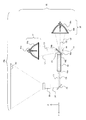
図1は、本発明の実施の形態1に係る投写型表示装置10aの構成を示す図である。図1に示すように、実施の形態1に係る投写型表示装置10aは、強度が均一化された光束L3を出射する光源装置30と、光源装置30から出射された光束L3を入力映像信号に応じて変調して画像光L4に変換する画像表示素子(ライトバルブ)20と、画像光L4をスクリーンSCに拡大投写する投写光学系50とを有している。
Embodiment 1 FIG.
FIG. 1 is a diagram showing a configuration of a
図1には、反射型の画像表示素子20を示しているが、画像表示素子20は、透過型の画像表示素子であってもよい。画像表示素子20は、例えば、液晶ライトバルブ、デジタルマイクロミラーデバイス(DMD)などである。背面投写型の投写型表示装置の場合には、スクリーンSCは投写型表示装置の一部である。また、光源装置30、画像表示素子20、投写光学系50及びスクリーンSCの配置は、図1に示した配置に限定されるものではない。
Although FIG. 1 shows a reflective
光源装置30は、第1の光軸C1を有し、第1の光束L1を出射する第1の光源ランプ(第1の光源手段)31と、第1の光軸C1に略直交する第2の光軸C2を有し、第2の光束L2を出射する第2の光源ランプ32(第2の光源手段)と、入射端40aに入射した光束を光強度分布が均一化された光束に変換して出射端40bから出射する光強度均一化素子(光強度均一化手段)40と、第1及び第2の光源ランプ31,32から出射された第1及び第2の光束L1,L2を入射端40aに集光させる反射透過素子60とを有している。なお、「略直交」とは、2つの対象物が互いに略垂直な関係にあることを言い、必ずしも交わっている必要はないものとする。
The
第1の光源ランプ31から出射される第1の光束L1及び第2の光源ランプ32から出射される第2の光束L2は、いずれも集光光束である。ここでは、第1の光源ランプ31の第1の光軸C1と、第2の光源ランプ32の第2の光軸C2とが一致しないように、第1の光源ランプ31、第2の光源ランプ32、反射透過素子60及び光強度均一化素子40が配置されている。図1に示した例では、第1の光源ランプ31の発光体31aから反射透過素子60までの第1の光軸C1と、光強度均一化素子40の光軸C3とが略直交し、なお且つ、第2の光源ランプ32の第2の光軸C2と、光強度均一化素子40の光軸C3とが平行になるように、第1の光源ランプ31、第2の光源ランプ32、反射透過素子60、及び光強度均一化素子40が配置されている。
The first light flux L1 emitted from the first
第1の光源ランプ31は、例えば、白色光を出射する発光体31aと、この発光体31aの周囲に設けられた楕円面鏡(第1の集光手段)31bとにより構成される。楕円面鏡31bは、楕円の第1中心に対応する第1焦点から出射された光束を反射して、楕円の第2中心に対応する第2焦点に集光させる。発光体31aは、楕円面鏡31bの第1焦点近傍に配置されており、この発光体31aから出射された光束は、楕円面鏡31bの第2焦点近傍(集光点F1)に集光する。
The first
第2の光源ランプ32は、例えば、白色光を出射する発光体32aと、この発光体32aの周囲に設けられた楕円面鏡(第2の集光手段)32bとにより構成される。楕円面鏡32bは、楕円の第1中心に対応する第1焦点から出射された光束を反射して、楕円の第2中心に対応する第2焦点に集光させる。発光体32aは、楕円面鏡32bの第1焦点近傍に配置されており、この発光体32aから出射された光束は、楕円面鏡32bの第2焦点近傍(集光点F2)に集光する。
The second
なお、楕円面鏡31b,32bに代えて放物面鏡を用いてもよい。この場合には、発光体31a,32aから出射された光束を放物面鏡により略平行化した後、コンデンサレンズ(図示せず)により集光させればよい。また、楕円面鏡31b,32bに代えて放物面鏡以外の凹面鏡を用いることもできる。また、3つ以上の光源ランプを設けることもできる。
A parabolic mirror may be used instead of the
以下の説明では、第1の光源ランプ31の第1の光軸C1と、第2の光源ランプ32の第2の光軸C2と、光強度均一化素子40の光軸C3とを含む面をZX面とし、ZX面に直交する方向をY方向とする。また、ZX面において、光強度均一化素子40の光軸C3の方向をX方向とし、これに直交する方向をZ方向とする。さらに、光強度均一化素子40の光軸C3に対して第1の光源ランプ31側を+Z方向、逆側を−Z方向とする。なお、これらの方向は、あくまでも説明の便宜のためのものであり、投写型表示装置10aの向きや配置を限定するものではない。
In the following description, a surface including the first optical axis C1 of the first
実施の形態1に係る投写型表示装置10aにおいては、第1の光束L1は、後述する反射透過素子60の反射膜60bで反射され、光強度均一化素子40の入射端40aの近傍の集光点F1に集光する。また、第2の光束L2は、後述する反射透過素子60の透過部材60aを介して、光強度均一化素子40の入射端40aの近傍の集光点F2に集光する。但し、第1の光束L1の集光点F1が、光強度均一化素子40の光軸C3に対して+Z側(第1の光源ランプ31側)に位置しているのに対して、第2の光束L2の集光点F2は、光強度均一化素子40の光軸C3に対して−Z側(集光点F1と反対の側)に位置している。
In the
つまり、実施の形態1に係る投写型表示装置10aにおいては、第1の光束L1の中心光線(反射透過素子60と光強度均一化素子40との間では、光軸C3に平行)が入射端40aに入射する第1の入射位置(第1の集光位置)と、第2の光束L2の中心光線(光軸C3に平行)が入射端40aに入射する第2の入射位置(第2の集光位置)とは、互いに異なる位置であり、且つ、いずれも光強度均一化素子40の光軸C3からずれた位置となる。
That is, in the
光強度均一化素子40は、第1の光束L1及び第2の光束L2の当該光束断面内(すなわち光軸C3に直交する平面内)における光強度を均一化する(すなわち、照度ムラを低減する)機能を有している。光強度均一化素子40としては、一般的に、ガラス又は樹脂等の透明材料で作製されたものであり、例えば、側壁内側が全反射面となるように構成された多角形柱状のロッド(すなわち、断面形状が多角形の柱状部材)、又は、光反射面を内側にして筒状に組み合わされ、断面形状が多角形のパイプ(管状部材)である。
The light
光強度均一化素子40が多角柱状のロッドである場合には、透明材料と空気界面との全反射作用を利用して光を複数回反射させた後に出射端から出射させる。光強度均一化素子40が多角形のパイプである場合には、パイプの内面(表面鏡)の反射作用を利用して光を複数回反射させた後に出射端(出射口)から出射させる。光強度均一化素子40は、光束の進行方向に適当な長さを確保すれば、内部で複数回反射した光が光強度均一化素子40の出射端40bの近傍に重畳照射され、光強度均一化素子40の出射端40b近傍においては、略均一な光強度分布が得られる。
In the case where the light
図2(a)〜(c)は、光強度均一化素子40の入射端40aにおける光強度分布を模式的に示す図である。図2(a)〜(c)において、濃度の濃く描かれている(黒色に近い)範囲は光強度が大きい(明るい)領域であり、濃度が薄くなるほど(白色に近づくほど)光強度が小さい(暗い)領域である。
2A to 2C are diagrams schematically showing the light intensity distribution at the
図2(a)は、光源ランプを1つのみ使用した比較例における光強度均一化素子40の入射端40aにおける光強度分布の一例を示している。図2(a)に示した比較例では、入射端40aの中央付近に光強度のピークがあり、周辺に向かって徐々に暗くなっている。
FIG. 2A shows an example of the light intensity distribution at the
図2(b)は、第1及び第2の光源ランプ31,32を使用した本実施の形態における光強度均一化素子40の入射端40aにおける光強度分布の一例を示している。図2(b)に示すように、光強度均一化素子40の入射端40aにおいて、第1の光源ランプ31の光照射領域と第2の光源ランプ32による光照射領域とが入射端40aにおいてほとんど重複しない。また、図2(c)に示すように、光強度均一化素子40の入射端40aにおいて、第1の光源ランプ31の光照射領域と第2の光源ランプ32による光照射領域とが概ね重複する光強度分布も可能である。
FIG. 2B shows an example of the light intensity distribution at the incident end 40 a of the light
図3は、図2(c)の光強度分布を実現する光源装置の光源ランプ31,32から光強度均一化素子40までの構成例を示す図である。この構成例では、光強度均一化素子40の入射端40a付近において、第1の光源ランプ31の光軸C1が光強度均一化素子40の光軸C3に対して一定の角度を有し、第2の光源ランプ32の光軸C2が光強度均一化素子40の光軸C3に対して同様に角度を有している。これにより、第1の光束L1及び第2の光束L2は、光強度均一化素子40の入射端40aと光軸C3が交わる位置(集光点F4)に概ね集光し、図2(c)の光強度分布が得られる。
FIG. 3 is a diagram illustrating a configuration example from the
なお、第1の光源ランプ31を傾斜させる代わりに、反射透過素子60を傾斜させることにより、集光点F4に第1の光束L1を集光させてもよく、図2(c)と同様の光束分布を得ることができる。
Instead of inclining the first
図4(a)は、比較例の光源装置における光源ランプ31,32から光強度均一化素子40までの部分を示す図である。光強度均一化素子40よりもスクリーンSC側の構成要素は省略している。図4(b)は、図4(a)に示した光強度均一化素子40と反射鏡61とを拡大して示す図である。
FIG. 4A is a diagram showing portions from the
この比較例では、反射鏡61は、透明部材61aの表面全体に反射膜61bを形成したものである。この反射鏡61の、光強度均一化素子40の光軸C3よりも−Z側(第1の光源31とは反対の側)の部分は、第2の光源ランプ32から光強度均一化素子40に向かう光路の一部を遮っている。そのため、第2の光源ランプ32より出射された第2の光束L2のうち、反射鏡61の光路を遮る上記部分に入射した光束は、図4(b)に破線(光束401)で示したような軌跡を描いて反射され、光強度均一化素子40には到達しない。その結果、光利用効率の低下を招く。
In this comparative example, the reflecting
第2の光束L2を、可能な限り光強度均一化素子40に到達させるためには、図5(a)に示すように、反射鏡61の光軸C3よりも−Z側の部分を面取り加工により除去する必要がある。図5(a)及び(b)は、比較例の光源装置における反射鏡61の面取り加工を説明するための図である。反射鏡の加工は非常に難しく、図5(b)に示すように、透過部材61aの厚みT1が1.1mm以上である場合、反射鏡61の先端の幅T2を0.5mm程度残すのが一般的であり、幅T2を0.5mm以下に加工しようとすると、歩留まりが低下して製造コストが上昇することが知られている。そのため、反射鏡61の一部を面取り加工する方法では、製造コストを上昇させずに光利用効率を改善することは難しい。
In order to make the second light beam L2 reach the light
図6(a)は、本実施の形態の作用を説明するための図であり、光強度均一化素子40及び反射透過素子60を拡大して示す図である。比較例の光源装置では、第2の光源ランプ32からの光束の一部(図4(b)に示した光束401)が光強度均一化素子40に到達しなかったのに対し、本実施の形態では、図6(a)に示すように、第2の光源ランプ32からの光束601が透過部材60aを透過し、光強度均一化素子40の入射端40aに入射するため、光利用効率を向上することができる。
FIG. 6A is a diagram for explaining the operation of the present embodiment, and is an enlarged view showing the light
図6(b)は、反射透過素子60を、光強度均一化素子40の側から見た図である。図6(b)に示すように、反射透過素子60は、光を透過する部材で形成された透過部材60aの表面に、反射膜60bを形成したものである。透過部材60aは耐熱部材であることが好ましく、水晶、サファイア、合成石英等が好ましい。反射膜60bは、誘電体多層膜、アルミ反射膜、銀反射膜等で形成されている。また、反射膜60bは、各光源ランプ31,32の集光点付近に配置されるため、耐熱コートが施されていることが好ましい。
FIG. 6B is a diagram of the reflection /
図7は、本実施の形態の作用を説明するための図である。ここでは、図7(a)に示すように、光強度均一化素子40を、光軸C3より+Z側(第1の光源ランプ31側)の部分と、光軸C3より−Z側(第1の光源ランプ31と反対側)の部分とに分割して、光利用効率を考える。光強度均一化素子40の光軸C3より+Z側(第1の光源ランプ31側)の部分を除去した残りの部分(分割素子)を、光強度均一化素子41とする。
FIG. 7 is a diagram for explaining the operation of the present embodiment. Here, as shown in FIG. 7 (a), the light
図7(b)は、本実施の形態における光源装置の第2の光源ランプ32、反射透過素子60及び光強度均一化素子41を示している。図7(c)は、比較例の光源装置の第2の光源ランプ32、反射鏡61及び光強度均一化素子41を示している。図7(b)に示すように、第2の光源ランプ32から出射された第2の光束L2は、光強度均一化素子41の入射端41aの中心に集光するものとする。
FIG. 7B shows the second
図7(c)に示す比較例では、第2の光源ランプ32から出射された第2の光束L2は、透過部材等を透過することなく、光強度均一化素子41に入射する。これに対し、図7(b)に示す本実施の形態では、第2の光源ランプ32から出射された第2の光束L2は、透過部材60aに入射して屈折作用を受けたのち、光強度均一化素子41に入射する。そのため、光強度均一化素子41への入射位置を同じとすると、図7(b)に示す本実施の形態では、図7(c)に示す比較例よりも、第2の光源ランプ32の光軸C2を−Z方向に移動させることとなる。その移動量は、透過部材60aの屈折率、及び、透過部材60aと光軸C3とのなす角度βにより決定され、例えば、0.数mmである。
In the comparative example shown in FIG. 7C, the second light beam L2 emitted from the second
図8(a)は、図7(b)に示した本実施の形態における光利用効率と、図7(c)に示した比較例における光利用効率のシミュレーション結果を示すグラフである。縦軸に示す相対光量比は、図7(a)に示したように第2の光源ランプ32から出射された第2の光束L2を光強度均一化素子41に直接(反射透過素子60や反射鏡61を介さずに)入射させた場合の光量を1とした場合の光量比である。
FIG. 8A is a graph showing a simulation result of the light use efficiency in the present embodiment shown in FIG. 7B and the light use efficiency in the comparative example shown in FIG. 7C. As shown in FIG. 7A, the relative light quantity ratio shown on the vertical axis indicates that the second light beam L2 emitted from the second
このシミュレーションでは、反射透過素子60の厚みT1を1.1mmとする。また、反射鏡61の厚みT1を1.1mmとし、図5(b)に示したように端部を面取り加工した残りの幅T2を変数とする。反射鏡61の幅T2は、加工精度上、少なくとも0.1mm以上であることが必要であるため、T2=0.1mm、0.3mm、0.5mm、0.7mm、0.9mm、1.1mmのそれぞれの場合についてシミュレーションを行った。なお、T2=1.1mmは、面取り加工を行わない場合に相当する。図8(a)の横軸は、反射鏡61の幅T2を示す。また、第2の光源ランプ32より出射される第2の光束L2と光軸C2とのなす角度αを30度とし、光軸C2と反射透過素子60及び反射鏡61とのなす角度βを45度とした。
In this simulation, the thickness T1 of the reflective /
図8(a)において、円形のプロット801は、本実施の形態に係る反射透過素子60を用いた場合(図7(b))の相対光量比を示す。なお、このプロットは、便宜上、T2=0の位置に示す。一方、直線800で結ばれた四角形のプロットは、比較例に係る反射鏡61を用いた場合(図7(c))の相対光量比である。
In FIG. 8A, a
以下の表1に、シミュレーションの結果を数値で示す。

図8(a)及び表1から、比較例(図7(c))における相対光量比が、最大でも約0.86(幅T2を0.1mmとした場合)であるのに対し、本実施の形態(図7(b))における相対光量比は約0.9となり、高い光利用効率が得られていることが分かる。 From FIG. 8A and Table 1, the relative light quantity ratio in the comparative example (FIG. 7C) is about 0.86 at the maximum (when the width T2 is set to 0.1 mm). The relative light quantity ratio in this form (FIG. 7B) is about 0.9, indicating that high light utilization efficiency is obtained.
また、表1より、比較例において、反射鏡61の幅T2が0.1mmから1.1mmと増加するにつれて、光利用効率が0.863から0.761に低下し、その低下幅は約12%(1−(0.761/0.863)≒0.118)であることが分かる。すなわち、面取り加工を全く行わない場合(すなわち幅T2が1.1mmの場合)、光利用効率が約12%低下することが分かる。また、比較例において、最も高い光利用効率0.863が得られているのは、反射鏡61の幅T2を0.1mmとした場合であるが、この場合には、上述したように製造ばらつきが大きくなり、製造コストが増加する要因となる。
Also, from Table 1, in the comparative example, as the width T2 of the reflecting
このように、本実施の形態によれば、反射透過素子60を用いることで、比較例の最も高い相対光量比(反射鏡61の幅T2が0.1mmの場合)と比較しても、さらに高い光利用効率を得ることができることが分かる。すなわち、本実施の形態では、反射透過素子60を用いることで、光利用効率を向上させることができると共に、面取り加工を不要にして製造コストを低減することができることが分かる。
As described above, according to the present embodiment, by using the reflective /
図8(b)に、本実施の形態において、第2の光源ランプ32から反射透過素子60に異なる角度で入射する光802a,802b,802cの軌跡を示す。第2の光源ランプ32及び光強度均一化素子40は、図示を省略している。光強度均一化素子40の入射端40a近傍の集光点F2では、反射透過素子60を通過して光強度均一化素子40の光軸C3と平行に進む光802bよりも光軸C3に近い側に、光802a及び光802cが収束していることが分かる。従って、光軸C3に対してより大きい角度を有する光802cは、光強度均一化素子40の入射端40aに到達しやすくなる。つまり、透過部材60aにおける屈折作用により、第2の光源ランプ32から出射された光のうち、光強度均一化素子40に入射する光の割合が増加する。また、光軸C3に対してより大きい角度を有する光802cは、反射膜60bによって遮られないため、効率よく入射端40aに入射させることができる。
FIG. 8B shows the trajectories of light 802a, 802b, and 802c that are incident on the reflection /
これに対し、図7(c)に示す比較例では、第2の光源ランプ32から出射され、光強度均一化素子40の光軸C2に対して角度を有する光が、光軸C2上に集光するため、本実施の形態のように光強度均一化素子40に入射する光の割合を増加する効果は得られない。
On the other hand, in the comparative example shown in FIG. 7C, light emitted from the second
本実施の形態では、光軸C2と反射透過素子60とのなす角度βを45度としたが、当該角度βは45度である必要はない。この場合、図9に示すように、第1の光源ランプ31の光軸C1と平行に進んだ光束が、光強度均一化素子40の入射端40aに垂直に入射するように、第1の光源ランプ31の光軸C1を角度βに合わせて傾けることが望ましい(なお、第2の光源ランプ32の光軸C2を傾ける必要はない)。輝度不変の法則より、有効光すなわちスクリーンSCに到達する光は、光強度均一化素子40の入射端40aの面積及び当該入射端40aへの光の有効入射角度、並びに、画像表示素子(ライトバルブ)20の面積及び画像表示素子20への有効入射角度により決定されるため、有効入射角度より角度が大きい光が入射端40aに入射した場合、スクリーンSCに到達しない光となるためである。
In the present embodiment, the angle β formed by the optical axis C2 and the reflection /
以上説明したように、実施の形態1に係る投写型表示装置10aは、第1の光源ランプ31から出射された第1の光束L1と第2の光源ランプ32から出射された第2の光束L2とを、反射透過素子60を用いてそれぞれ光強度均一化素子40に集光させるよう構成したため、反射鏡61を用いた場合のように光束が遮られることなく、光利用効率を高くすることができる。また、反射鏡61を用いた場合のような面取り加工が不要であるため、製造が容易になり、製造コストを低減することができる。
As described above, the
また、実施の形態1に係る投写型表示装置10aは、第1の光源ランプ31と第2の光源ランプ32とが対向配置されていないため、各光源ランプが、対向する光源ランプからの光によって加熱されることがなく、これにより、光源装置30の長寿命化に資することができる。
Further, in the
実施の形態2.
図10は、本発明の実施の形態2に係る投写型表示装置10bの光源装置30の構成を示す図である。図10に示した第1の光源ランプ31、第2の光源ランプ32、光強度均一化素子40、画像表示素子20、投写光学系50及びスクリーンSCは、それぞれ実施の形態1(図1)と同様に構成されている。実施の形態2に係る投写型表示装置10bは、反射透過素子64の構成が、実施の形態1に係る投写型表示装置10aの反射透過素子60と相違するものである。
FIG. 10 is a diagram showing a configuration of the
図11(a)は、第1の光源ランプ31から出射された第1の光束L1及び第2の光源ランプ32から出射された第2の光束L2が、光強度均一化素子40の入射端40aに形成する集光点F1,F2の例を示す図である。図11(a)に示すように、第1の光源ランプ31から出射された第1の光束L1の集光点F1と、第2の光源ランプ32から出射された第2の光束L2の集光点F2とは、光強度均一化素子40の入射端40aにおいて、Z方向だけでなくY方向にも互いにシフトした位置にある。
In FIG. 11A, the first light beam L1 emitted from the first
図11(b)は、反射透過素子64を、光強度均一化素子40の側から観察した図である。図11(b)に示すように、反射透過素子64において、第1の光源ランプ31から出射された光束L1の入射光量が最大の領域(最も明るい領域)を領域110aとし、第2の光源ランプ32から出射される光束L2の入射光量が最大の領域(最も明るい領域)を領域110bとする。反射透過素子64の反射膜64bは、その境界線112が、領域110a,110bを結ぶ直線111に対して垂直となるように形成されている。
FIG. 11B is a diagram in which the reflection /
実施の形態2に係る投写型表示装置10bによれば、反射透過素子64を上記のように構成することにより、第1の光源ランプ31から出射された第1の光束L1及び第2の光源ランプ32から出射された第2の光束L2を、無駄なく光強度均一化素子40の入射端40aに集光させることができるため、光利用効率が向上し、最適な光利用効率を得ることができる。
According to the
実施の形態3.
図12は、本発明の実施の形態3に係る投写型表示装置10cの光源装置30の構成を示す図である。図12に示した第2の光源ランプ32、光強度均一化素子40、画像表示素子20、投写光学系50及びスクリーンSCは、それぞれ実施の形態1(図1)と同様に構成されている。一方、実施の形態3における第1の光源ランプ31は、実施の形態1で説明した発光体31a及び楕円面鏡31bを有しているが、光軸C1が、第2の光源ランプ32の光軸C2及び光強度均一化素子40の光軸C3と平行である点で、実施の形態1の第1の光源ランプ31と相違している。また、実施の形態3における光源装置30は、第1の光源ランプ31から光強度均一化素子40までの光路に以下のような構成要素を有している点で、実施の形態1の光源装置30と相違している。
Embodiment 3 FIG.
FIG. 12 is a diagram showing the configuration of the
実施の形態3に係る投写型表示装置10cは、第1の光源ランプ31から出射された第1の光束L1を、反射透過素子60に向けて反射する第1の折り曲げミラー121と、折り曲げミラー121で反射された光束L1を伝達するレンズ120a,120bからなるリレー光学系120とを備えている。第1の光源ランプ31及び第1の折り曲げミラー121は、第1の光源ランプ31から出射された第1の光束L1が、第1の折り曲げミラー121の反射透過素子60側(光強度均一化素子40側)の集光点F3に集光するように配置されている。また、集光点F3で集光した第1の光束L1が、リレー光学系120及び反射透過素子60を介して、光強度均一化素子40の入射端40aの近傍の集光点F1に集光するように、リレー光学系120(レンズ120a,レンズ120b)、反射透過素子60及び光強度均一化素子40が配置されている。
The
光強度均一化素子40の入射端40aにおいて、第1の光束L1のうち光軸C3に平行な中心光線が入射する第1の集光位置と、第2の光束L2のうち光軸C3に平行な中心光線が入射する第2の集光位置とは、互いに異なる位置であり、なお且つ、いずれも光強度均一化素子40の光軸C3からずれている。なお、図12に示した例では、集光点F3が、第1の折り曲げミラー121の反射透過素子60側(光強度均一化素子40側)に位置しているが、これに限定されるものではなく、集光点F3が、第1の折り曲げミラー121の第1の光源ランプ31側に位置していてもよい。
At the
図12に示した構成では、第1の折り曲げミラー121及び反射透過素子60は光軸C3に対して45度傾いて配置されているが、この傾き角度に制限はない。但し、第1の折り曲げミラー121及び反射透過素子60は、光軸C3に対して同様の傾き角度を有することが好ましく、さらに、当該傾き角度に応じてリレー光学系120を配置することが好ましい。図13は、第1の折り曲げミラー121及び反射透過素子60を、光軸C3に対してそれぞれ45度以上に傾けた構成を示す。このように、第1の折り曲げミラー121及び反射透過素子60を光軸C3に対して45度以上傾けることにより、第1の光源ランプ31と第2の光源ランプ32との間隔を広げて配置することができるため、両光源ランプ31,32の冷却が容易となり、また、投写型表示装置を小型化することもできる。
In the configuration shown in FIG. 12, the
以上説明したように、実施の形態3に係る投写型表示装置10cは、第1の光源ランプ31と第2の光源ランプ32とを対向して配置していないため、各光源ランプが、対向する光源ランプからの光によって加熱されることがなく、これにより、光源装置30の長寿命化に資することができる。
As described above, in the
また、実施の形態3に係る投写型表示装置10cでは、折り曲げミラー121の反射透過素子60側(光強度均一化素子40側)に集光点F3が位置するように各構成要素が配置されているため、折り曲げミラー121の発熱を抑制することができる。このため、別途、冷却装置等を設置する必要がなく、投写型表示装置10cの構成の簡素化及び製造コストの低減を実現できる。
In the
さらに、実施の形態3に係る投写型表示装置10cでは、第1の光源ランプ31と第2の光源ランプ32とが平行に配置されているため、投写光学系50による投写光軸方向を±Y方向とし、スクリーンSCをZX面に平行にすることが可能となる。これに対し、実施の形態1に示すような第1の光源ランプ31と第2の光源ランプ32とが略直交して配置された構成において、投写光学系50による投写光軸方向を+Y方向とすると、第1の光源ランプ31の発光体31a内の温度分布が不均一となるため、好ましくない。これは、発光体31aは、一般に、光軸C1の方向に一対の電極を対向配置した構成を有しているため、投写光学系50の投写光軸方向を+Y方向とすると(実施の形態1の構成では、第1の光源ランプ31の光軸C1がY方向となる)、一対の電極が上下方向に位置することとなり、その結果、上側に位置する電極の温度が過度に上昇して電極摩耗(溶融)を生じ、ランプの寿命が短くなる可能性があるためである。
Further, in the
図14は、実施の形態3のリレー光学系120の一構成例を説明するための図である。図14では、第1の折り曲げミラー121及び反射透過素子60を省略し、第1の光源ランプ31及びリレー光学系120のみ示す。図14に示すように、リレー光学系120のレンズ120aは、第1の光源ランプ31から出射されて集光点F3に一旦集光した第1の光束L1を、光軸C1に対して略平行にする作用を有している。従って、レンズ120aの焦点位置は、概ね集光点F3の位置となる。
FIG. 14 is a diagram for explaining a configuration example of the relay
ここで、一般に、集光点F3の位置には、光源ランプの個体差によるばらつきがある。つまり、レンズ120aと集光点F3との間隔が、光源ランプの個体差によって変動する可能性がある。そこで、実施の形態3では、レンズ120aを、光軸C1上を移動させる調整機構122を設けることにより、光源ランプの個体差に起因する集光点F3の位置のばらつきを解消し、光利用効率の低下を抑制している。
Here, generally, the position of the condensing point F3 has a variation due to individual differences of the light source lamps. That is, there is a possibility that the distance between the
図14(b)に、集光点F3の位置が変化した場合の第1の光束L1の軌跡を示す。図14(b)では、図14(a)に示した場合と比較して、レンズ120aと集光点F3との間隔が広くなっている。そのため、光強度均一化素子40の入射端40aの近傍の集光点F1が、第1の光源ランプ31側に近づく(すなわち、光強度均一化素子40の入射端40aから離れる)こととなり、光利用効率が低下する。逆に、レンズ120aと集光点F3の間隔が狭くなった場合は、集光点F1が、図14(a)と比較して第1の光源ランプ31から離間するため、やはり光利用効率が低下する。
FIG. 14B shows a locus of the first light beam L1 when the position of the condensing point F3 is changed. In FIG. 14B, the distance between the
この実施の形態3では、集光点F3の位置が変化しても、調整機構122を用いて、レンズ120aを、当該レンズ120aが第1の光束L1を光軸C1に対して略平行光にする位置に位置調整することにより、集光点F1を変化させないようにすることができ、光強度均一化素子40の入射端40aの近傍に確実に位置させることができる。そのため、光利用効率の低下を防止することができる。
In the third embodiment, even if the position of the condensing point F3 changes, the
すなわち、実施の形態3に係る投写型表示装置10cでは、リレー光学系120の第1の光源ランプ31側に位置するレンズ120aの位置を調整する調整機構122を設けることにより、光利用効率の低下を抑制することができる。
That is, in the
10a,10b,10c 投写型表示装置、 30 光源装置、 31 第1の光源ランプ、 31a,32a 発光体、 31b,32b 楕円面鏡、 C1 第1の光源ランプの光軸、 32 第2の光源ランプ、 C2 第2の光源ランプの光軸、 40 光強度均一化素子、 40a 入射端、 40b 出射端、 C3 光強度均一化素子の光軸、 20 画像表示素子、 50 投写光学系、 60 反射透過素子、 60a 透過部材、 60b 反射膜、 120 リレー光学系、 120a,120b レンズ、 122 調整機構、 L1 第1の光束、 L2 第2の光束、 L3 光強度均一化素子からの出射光束、 L4 画像光、 F1,F2 集光点。
10a, 10b, 10c Projection display device, 30 light source device, 31 first light source lamp, 31a, 32a illuminant, 31b, 32b ellipsoidal mirror, C1 optical axis of first light source lamp, 32 second light source lamp C2 optical axis of the second light source lamp, 40 light intensity uniformizing element, 40a incident end, 40b emission end, C3 optical axis of the light intensity uniformizing element, 20 image display element, 50 projection optical system, 60 reflection /
Claims (8)
前記第1の光源手段の前記第1の光軸と一致しない第2の光軸を有し、第2の光束を出射する第2の光源手段と、
入射端と出射端とを有し、前記入射端に入射された光束を複数回反射させて強度分布が均一化された光束に変換して前記出射端から出射する柱状の光強度均一化手段と、
反射部と透過部とを有し、前記第1の光源手段から出射された前記第1の光束を前記反射部により反射して前記入射端に集光させ、前記第2の光源手段から出射された前記第2の光束を前記透過部を透過させて前記入射端に集光させる反射透過素子と、
前記光強度均一化手段の前記出射端から出射された光束を変調して画像光に変換する画像表示素子と、
前記画像光をスクリーンに投写する投写光学系と
を備え、
前記反射部と前記透過部とは、異なる領域に互いに隣接して形成され、境界線により分けられ、
前記境界線は、前記反射部における前記第1の光束の入射光量が最大の位置と、前記透過部における前記第2の光束の入射光量が最大の位置とを結ぶ直線に直交するように延在している
ことを特徴とする投写型表示装置。 First light source means having a first optical axis and emitting a first luminous flux;
Second light source means for emitting a second light beam, having a second optical axis that does not coincide with the first optical axis of the first light source means;
A columnar light intensity uniformizing means that has an incident end and an exit end, reflects the light beam incident on the incident end a plurality of times, converts it into a light beam having a uniform intensity distribution, and emits the light from the exit end; ,
A reflection unit and a transmission unit; the first light beam emitted from the first light source unit is reflected by the reflection unit to be condensed at the incident end and is emitted from the second light source unit; A reflective / transmissive element that transmits the second light flux through the transmission unit and collects the second light flux at the incident end;
An image display element that modulates a light beam emitted from the exit end of the light intensity uniformizing means and converts it into image light;
A projection optical system for projecting the image light onto a screen,
The reflection part and the transmission part are formed adjacent to each other in different areas, and are separated by a boundary line,
The boundary line extends so as to be orthogonal to a straight line connecting a position where the incident light amount of the first light beam in the reflecting portion is maximum and a position where the incident light amount of the second light beam in the transmission portion is maximum. A projection display device characterized by that .
前記反射部と前記透過部とが同一平面に形成されているThe reflection part and the transmission part are formed on the same plane.
ことを特徴とする請求項1に記載の投写型表示装置。The projection display device according to claim 1.
さらに、
前記第1の光源手段から出射された前記第1の光束の光路を折り曲げる反射鏡と、
前記反射鏡から反射された前記第1の光束を前記反射透過素子に導くリレー光学系と
を備えたことを特徴とする請求項1から3までの何れか1項に記載の投写型表示装置。 The first light source means and the second light source means are arranged so that the first optical axis and the second optical axis are parallel to each other,
further,
A reflecting mirror for bending the optical path of the first light beam emitted from the first light source means;
The projection display device according to any one of claims 1 to 3, characterized in that a relay optical system for guiding the first light beam reflected from the reflecting mirror to the reflection-transmission element.
前記第1のレンズを、前記第1の光源手段の前記第1の光軸に沿って移動させる調整機構が設けられていることを特徴とする請求項5に記載の投写型表示装置。 The relay optical system includes a first lens that converts the first light beam emitted from the first light source unit into parallel light, and the first light beam that has been converted into parallel light by the first lens. A second lens for condensing at the incident end of the light intensity uniformizing means,
6. The projection display device according to claim 5 , further comprising an adjustment mechanism for moving the first lens along the first optical axis of the first light source means.
前記第1の光源手段の前記第1の光軸と一致しない第2の光軸を有し、第2の光束を出射する第2の光源手段と、
入射端と出射端とを有し、前記入射端に入射された光束を複数回反射させて強度分布が均一化された光束に変換して前記出射端から出射する柱状の光強度均一化手段と、
反射部と透過部とを有し、前記第1の光源手段から出射された前記第1の光束を前記反射部により反射して前記入射端に集光させ、前記第2の光源手段から出射された前記第2の光束を前記透過部を透過させて前記入射端に集光させる反射透過素子と
を備え、
前記反射部と前記透過部とは、異なる領域に互いに隣接して形成され、境界線により分けられ、
前記境界線は、前記反射部における前記第1の光束の入射光量が最大の位置と、前記透過部における前記第2の光束の入射光量が最大の位置とを結ぶ直線に直交するように延在している
ことを特徴とする光源装置。 First light source means having a first optical axis and emitting a first luminous flux;
Second light source means for emitting a second light beam, having a second optical axis that does not coincide with the first optical axis of the first light source means;
A columnar light intensity uniformizing means that has an incident end and an exit end, reflects the light beam incident on the incident end a plurality of times, converts it into a light beam having a uniform intensity distribution, and emits the light from the exit end; ,
A reflection unit and a transmission unit; the first light beam emitted from the first light source unit is reflected by the reflection unit to be condensed at the incident end and is emitted from the second light source unit; And a reflection / transmission element for condensing the second light flux through the transmission part and condensing at the incident end,
The reflection part and the transmission part are formed adjacent to each other in different areas, and are separated by a boundary line,
The boundary line extends so as to be orthogonal to a straight line connecting a position where the incident light amount of the first light beam in the reflecting portion is maximum and a position where the incident light amount of the second light beam in the transmission portion is maximum. A light source device characterized by that .
Priority Applications (1)
| Application Number | Priority Date | Filing Date | Title |
|---|---|---|---|
| JP2009140870A JP5377097B2 (en) | 2009-06-12 | 2009-06-12 | Projection display device and light source device |
Applications Claiming Priority (1)
| Application Number | Priority Date | Filing Date | Title |
|---|---|---|---|
| JP2009140870A JP5377097B2 (en) | 2009-06-12 | 2009-06-12 | Projection display device and light source device |
Publications (3)
| Publication Number | Publication Date |
|---|---|
| JP2010286688A JP2010286688A (en) | 2010-12-24 |
| JP2010286688A5 JP2010286688A5 (en) | 2012-07-19 |
| JP5377097B2 true JP5377097B2 (en) | 2013-12-25 |
Family
ID=43542428
Family Applications (1)
| Application Number | Title | Priority Date | Filing Date |
|---|---|---|---|
| JP2009140870A Expired - Fee Related JP5377097B2 (en) | 2009-06-12 | 2009-06-12 | Projection display device and light source device |
Country Status (1)
| Country | Link |
|---|---|
| JP (1) | JP5377097B2 (en) |
Families Citing this family (1)
| Publication number | Priority date | Publication date | Assignee | Title |
|---|---|---|---|---|
| WO2012104958A1 (en) * | 2011-01-31 | 2012-08-09 | Necディスプレイソリューションズ株式会社 | Light source device and projection display device |
Family Cites Families (2)
| Publication number | Priority date | Publication date | Assignee | Title |
|---|---|---|---|---|
| NO319879B1 (en) * | 2002-05-03 | 2005-09-26 | Projectiondesign As | A multi-lamp arrangement for optical systems |
| JP2007294338A (en) * | 2006-04-27 | 2007-11-08 | Seiko Epson Corp | Lighting system and projector |
-
2009
- 2009-06-12 JP JP2009140870A patent/JP5377097B2/en not_active Expired - Fee Related
Also Published As
| Publication number | Publication date |
|---|---|
| JP2010286688A (en) | 2010-12-24 |
Similar Documents
| Publication | Publication Date | Title |
|---|---|---|
| EP1398659B1 (en) | Illumination apparatus and image projection apparatus using the illumination apparatus | |
| EP2988170B1 (en) | Light-emitting device and projection system | |
| JP2008288215A (en) | Optical system for fresnel lens light, especially for spotlight or floodlight | |
| JP6108666B2 (en) | Image projection device | |
| JP2018189686A (en) | Light source device and projection display device | |
| KR100550409B1 (en) | Light source unit and projection type display device using thereof | |
| JP2011248327A (en) | Illumination device and projection type display apparatus provided therewith | |
| JP2006308778A (en) | Two-lamp synthetic optical system and image projecting device equipped with same | |
| US10564532B2 (en) | Optical unit and projector including the same | |
| US8414132B2 (en) | Multiple-lights-combining illumination device and projection-type display apparatus using the same | |
| JP5162901B2 (en) | Projection display device and optical unit | |
| US7438424B2 (en) | Illumination optical apparatus and projection type display apparatus | |
| JP2008046479A (en) | Lighting optical system and projection type image display device provided therewith | |
| JP2010091846A (en) | Projection display device | |
| JP5377097B2 (en) | Projection display device and light source device | |
| JPH10241437A (en) | Light source device, illumination system, and image projection device | |
| JP4879056B2 (en) | Projection display | |
| TWI731332B (en) | Projection device and fabrication method thereof | |
| JP5609158B2 (en) | Light source device and projection display device | |
| JP4562687B2 (en) | Condensing optical system and image projection apparatus | |
| JP2011164122A (en) | Reflector system and projector | |
| JPH11283422A (en) | Light source device | |
| TW586018B (en) | Multi-lamp illumination system | |
| KR0155771B1 (en) | Parallel ray illuminator | |
| JP2023107320A (en) | Light source device and image projecting apparatus |
Legal Events
| Date | Code | Title | Description |
|---|---|---|---|
| A521 | Written amendment |
Free format text: JAPANESE INTERMEDIATE CODE: A523 Effective date: 20120531 |
|
| A621 | Written request for application examination |
Free format text: JAPANESE INTERMEDIATE CODE: A621 Effective date: 20120531 |
|
| A977 | Report on retrieval |
Free format text: JAPANESE INTERMEDIATE CODE: A971007 Effective date: 20130430 |
|
| A131 | Notification of reasons for refusal |
Free format text: JAPANESE INTERMEDIATE CODE: A131 Effective date: 20130507 |
|
| A521 | Written amendment |
Free format text: JAPANESE INTERMEDIATE CODE: A523 Effective date: 20130701 |
|
| TRDD | Decision of grant or rejection written | ||
| A01 | Written decision to grant a patent or to grant a registration (utility model) |
Free format text: JAPANESE INTERMEDIATE CODE: A01 Effective date: 20130827 |
|
| A61 | First payment of annual fees (during grant procedure) |
Free format text: JAPANESE INTERMEDIATE CODE: A61 Effective date: 20130924 |
|
| R150 | Certificate of patent or registration of utility model |
Free format text: JAPANESE INTERMEDIATE CODE: R150 |
|
| R250 | Receipt of annual fees |
Free format text: JAPANESE INTERMEDIATE CODE: R250 |
|
| LAPS | Cancellation because of no payment of annual fees |