JP5376589B2 - Tire manufacturing apparatus and tire manufacturing method - Google Patents
Tire manufacturing apparatus and tire manufacturing method Download PDFInfo
- Publication number
- JP5376589B2 JP5376589B2 JP2009198340A JP2009198340A JP5376589B2 JP 5376589 B2 JP5376589 B2 JP 5376589B2 JP 2009198340 A JP2009198340 A JP 2009198340A JP 2009198340 A JP2009198340 A JP 2009198340A JP 5376589 B2 JP5376589 B2 JP 5376589B2
- Authority
- JP
- Japan
- Prior art keywords
- unvulcanized tread
- unvulcanized
- molded body
- tread
- diameter
- Prior art date
- Legal status (The legal status is an assumption and is not a legal conclusion. Google has not performed a legal analysis and makes no representation as to the accuracy of the status listed.)
- Active
Links
Images


Abstract
Description
本発明は、被成形体の外周に未加硫トレッドを貼り付けて未加硫タイヤを成形するタイヤ製造装置及びタイヤ製造方法に関する。 The present invention relates to a tire manufacturing apparatus and a tire manufacturing method for forming an unvulcanized tire by attaching an unvulcanized tread to the outer periphery of a molded body.
未加硫タイヤの成形工程では、被成形体の外周に未加硫トレッドを配置した後、未加硫トレッドを押圧して対向する被成形体に圧着することが行われている。また、従来、膨出させた被成形体の外周に帯状の未加硫トレッドを1周巻き付けてステッチングし、未加硫トレッドを被成形体の外周に貼り付けて未加硫タイヤを成形し、自動二輪車用タイヤを製造する方法が知られている(特許文献1参照)。 In the unvulcanized tire molding step, an unvulcanized tread is disposed on the outer periphery of the molded body, and then the unvulcanized tread is pressed and pressed against the opposed molded body. Conventionally, a belt-like unvulcanized tread is wound once around the outer periphery of the swelled molded body and stitched, and the unvulcanized tread is attached to the outer periphery of the molded body to form an unvulcanized tire. A method for manufacturing a motorcycle tire is known (see Patent Document 1).
図13は、このようにしてタイヤを製造する従来のタイヤ製造方法の例を模式的に示すタイヤ幅方向の断面図であり、ここでは、モーターサイクル用のタイヤの製造手順を示している。
図示の例では、まず、成形ドラム(図示せず)を用いて、カーカスプライやビードコア等の各種タイヤ構成部材を組み合わせて円筒状に形成し、その中央部を膨出(図13A参照)させて、外周面の所定範囲にコードCを螺旋状に巻き付けてベルト(スパイラルベルト)Bを形成する。
FIG. 13 is a cross-sectional view in the tire width direction schematically showing an example of a conventional tire manufacturing method for manufacturing a tire in this way, and shows a manufacturing procedure of a motorcycle tire.
In the illustrated example, first, using a forming drum (not shown), various tire constituent members such as a carcass ply and a bead core are combined to form a cylindrical shape, and a central portion thereof is expanded (see FIG. 13A). Then, a cord C is spirally wound around a predetermined range of the outer peripheral surface to form a belt (spiral belt) B.
次に、このように成形した被成形体Hの外周(図13B参照)に、帯状の未加硫トレッドTを1周巻き付けた後、被成形体Hを回転させて、一対の押圧ローラ100を、未加硫トレッドTの外周面に押し付けて幅方向(図13では左右方向)の中央部から両外側に向かって移動させる。これにより、一対の押圧ローラ100(図13C参照)を未加硫トレッドTの外周面に沿って移動させて未加硫トレッドTを螺旋状に押圧し、その全体に亘りステッチングして未加硫トレッドTを被成形体Hに圧着する。未加硫トレッドTは、ステッチングに伴い、幅方向の端部に向かって次第に大きく半径方向内側(図13Cでは下側)に絞り込まれて、被成形体Hの曲面状の外周面に合わせて変形し、内周面が被成形体Hの外周面に密着して貼り付けられる。
Next, the belt-shaped unvulcanized tread T is wound around the outer periphery (see FIG. 13B) of the molded body H formed in this way, and then the molded body H is rotated, so that the pair of
その際、未加硫トレッドTの側部は、変形前後で周方向長さが変化するため、その差に応じた余剰な部分が重なり合う等して、表面に皺や波状の起伏が発生し易い。これに伴い、成形後の未加硫タイヤには、未加硫トレッドTの側部(図13CのZ範囲)を中心に、厚さ(ゲージ)や外観にバラツキが生じて均一性が低下し、サイド部に皺等の凹凸が発生することがある。特に、モーターサイクル用のタイヤでは、サイズ(幅)が大きくなるのに応じて、タイヤ幅方向中央部と側部との直径差も大きくなるため、未加硫トレッドTの側部を変形させる量も多くなり、発生する凹凸も大きく、又は、多くなる傾向がある。このように未加硫タイヤのサイド部に凹凸が発生すると、場合によっては、加硫後のタイヤの表面に多少の凹凸やベア等の外観上の問題が発生する虞もあり、例えば加硫時に未加硫タイヤの表面に外面液を塗布する等して凹凸に対処する必要がある。 At that time, since the circumferential length of the side portion of the unvulcanized tread T changes before and after the deformation, excessive portions corresponding to the difference overlap, and so on, the surface is likely to generate wrinkles and wavy undulations. . Along with this, the uncured tire after molding has a variation in thickness (gauge) and appearance around the side of the unvulcanized tread T (Z range in FIG. 13C), and the uniformity decreases. Unevenness such as wrinkles may occur on the side part. In particular, in a motorcycle tire, as the size (width) increases, the difference in diameter between the center portion and the side portion in the tire width direction also increases, so the amount of deformation of the side portion of the unvulcanized tread T And the generated irregularities tend to be large or increase. If unevenness occurs in the side portion of the unvulcanized tire in this way, in some cases, there may be some unevenness on the surface of the tire after vulcanization or appearance problems such as bares. It is necessary to deal with unevenness by applying an outer surface liquid to the surface of the unvulcanized tire.
しかしながら、未加硫トレッドTの凹凸の程度が大きくなるのに伴い、凹凸への対処は困難になり、加硫時に問題が生じる虞も大きくなる。そのため、これらに対し、より適切かつ効果的に対処する観点から、未加硫トレッドTの表面に発生する凹凸を抑制することが要求されている。また、タイヤの周方向に沿う厚さの均一性を高めてユニフォーミティの一層の向上を図る観点からも、未加硫トレッドTを被成形体Hに均一に精度よく貼り付けて、未加硫タイヤの厚さのバラツキを低減させることが求められている。 However, as the degree of unevenness of the unvulcanized tread T increases, it becomes difficult to deal with the unevenness, and the risk of problems during vulcanization increases. Therefore, from the viewpoint of dealing with these more appropriately and effectively, it is required to suppress unevenness generated on the surface of the unvulcanized tread T. In addition, from the viewpoint of further improving the uniformity by increasing the uniformity of the thickness along the circumferential direction of the tire, the unvulcanized tread T is uniformly and accurately attached to the molded body H, and the unvulcanized There is a demand for reducing variations in tire thickness.
本発明は、このような従来の問題に鑑みなされたものであって、その目的は、未加硫タイヤの成形時に、未加硫トレッドを、被成形体の外周に沿うように収縮させて、表面の凹凸を抑制して被成形体の外周に精度よく貼り付けることである。また、被成形体に貼り付けた未加硫トレッドの周方向の均一性を高めて、タイヤのユニフォーミティを向上させることである。 The present invention has been made in view of such conventional problems, and its purpose is to shrink an unvulcanized tread along the outer periphery of a molded body when molding an unvulcanized tire, In other words, the surface unevenness is suppressed and the surface is adhered to the outer periphery of the molded body with high accuracy. Another object of the present invention is to improve the uniformity of the tire by increasing the uniformity in the circumferential direction of the unvulcanized tread adhered to the molded body.
本発明は、被成形体の外周に未加硫トレッドを貼り付けて未加硫タイヤを成形するタイヤ製造装置であって、外周に環状の未加硫トレッドが形成される拡縮可能なドラムと、ドラムを拡径させて、環状の未加硫トレッドを拡径させる拡径手段と、拡径させた未加硫トレッドを保持する保持手段と、保持手段が保持する未加硫トレッドを被成形体の外周に対向させて配置する配置手段と、被成形体の外周に対向する未加硫トレッドの保持手段による保持を解除させる保持解除手段と、保持手段による保持を解除した未加硫トレッドを被成形体に押圧し、被成形体の外周に圧着して貼り付ける押圧手段と、を備え、ドラムが、ドラム周方向に配置された拡縮変位可能な複数のセグメントと、複数のセグメントを囲んで配置された弾性バンドを有し、セグメントと接触する弾性バンドの内周面とセグメントとの摩擦係数を、前記セグメントの拡径に伴う弾性バンドの拡径変形時に、セグメントに対して滑りが可能な値にしたことを特徴とする。
また、本発明は、被成形体の外周に未加硫トレッドを貼り付けて未加硫タイヤを成形するタイヤ製造方法であって、ドラムの周方向に配置された複数のセグメントを囲む弾性バンドの外周面に、被成形体の外径よりも内径が小さい環状の未加硫トレッドを形成する工程と、複数のセグメントを拡径変位させる工程と、弾性バンドを内周面に接触するセグメントの拡径変位に合わせて弾性変形させ、環状の未加硫トレッドの内径を被成形体の外径よりも大きく拡径する工程と、拡径させた未加硫トレッドを保持して被成形体の外周に対向させて配置する工程と、未加硫トレッドの保持を解除して、未加硫トレッドを対向する被成形体の外周に向けて収縮させる工程と、収縮した未加硫トレッドを被成形体に押圧し、未加硫トレッドを被成形体の外周に圧着して貼り付ける工程と、を有し、セグメントと接触する弾性バンドの内周面とセグメントとの摩擦係数を、前記セグメントの拡径に伴う弾性バンドの拡径変形時に、セグメントに対して滑りが可能な値にしたことを特徴とする。
The present invention is a tire manufacturing apparatus for forming an unvulcanized tire by attaching an unvulcanized tread to the outer periphery of a molded body, and an expandable / contractable drum in which an annular unvulcanized tread is formed on the outer periphery, Diameter expansion means for expanding the diameter of the drum to expand the annular unvulcanized tread, holding means for holding the expanded unvulcanized tread, and unvulcanized tread held by the holding means to be molded An arrangement means arranged to face the outer circumference of the molding body, a holding release means for releasing the holding of the unvulcanized tread facing the outer circumference of the molded body, and an unvulcanized tread released from holding by the holding means. A pressing unit that presses the molded body and presses and adheres to the outer periphery of the molded body, and the drum is disposed in a circumferential direction of the drum and is disposed so as to surround the plurality of segments. an elastic band that has been The friction coefficient between the inner peripheral surface and the segments of the elastic band in contact with the segments, when expanded deformation of the elastic band associated with the diameter of the segments, characterized in that the possible slip value for the segment.
The present invention also relates to a tire manufacturing method for forming an unvulcanized tire by attaching an unvulcanized tread to the outer periphery of a molded body, and comprising an elastic band surrounding a plurality of segments arranged in the circumferential direction of the drum. A step of forming an annular unvulcanized tread having an inner diameter smaller than the outer diameter of the molded body on the outer peripheral surface, a step of expanding and displacing a plurality of segments, and an expansion of the segment contacting the elastic band with the inner peripheral surface. A process of elastically deforming in accordance with the radial displacement and expanding the inner diameter of the annular unvulcanized tread to be larger than the outer diameter of the molded body, and holding the expanded unvulcanized tread and holding the outer circumference of the molded body A step of disposing the unvulcanized tread, releasing the unvulcanized tread, and shrinking the unvulcanized tread toward the outer periphery of the opposed molded body, and the contracted unvulcanized tread to be molded. And press the unvulcanized tread Includes a step of attaching and pressed in circumference, and the friction coefficient between the inner peripheral surface and the segments of the elastic band in contact with the segment, when expanded deformation of the elastic band associated with the diameter of the segment, the segment On the other hand, it is characterized by a value that allows sliding .
本発明によれば、未加硫タイヤの成形時に、未加硫トレッドを、被成形体の外周に沿うように収縮させて、表面の凹凸を抑制して被成形体の外周に精度よく貼り付けることができる。また、被成形体に貼り付けた未加硫トレッドの周方向の均一性を高めて、タイヤのユニフォーミティを向上させることができる。 According to the present invention, at the time of molding an unvulcanized tire, the unvulcanized tread is shrunk along the outer periphery of the molded body, and the unevenness on the surface is suppressed, and the unvulcanized tread is adhered to the outer periphery of the molded body with high accuracy. be able to. Moreover, the uniformity of the circumferential direction of the unvulcanized tread affixed to the to-be-molded body can be improved, and the uniformity of the tire can be improved.
以下、本発明のタイヤ製造装置とタイヤ製造方法の一実施形態について、図面を参照して説明する。
本実施形態のタイヤ製造装置は、被成形体の外周に環状(筒状)の未加硫トレッドの内周を貼り付けて未加硫タイヤを成形し、例えば自動二輪車用や乗用車用の空気入りタイヤや、他の気体を充填したタイヤ等、トレッドを有するタイヤを製造する。以下では、モーターサイクル用タイヤを例に採り、その未加硫タイヤを成形する手順や動作等について説明する。
Hereinafter, an embodiment of a tire manufacturing apparatus and a tire manufacturing method of the present invention will be described with reference to the drawings.
The tire manufacturing apparatus according to the present embodiment forms an unvulcanized tire by attaching an inner periphery of an annular (cylindrical) unvulcanized tread to the outer periphery of a molded body, for example, for a motorcycle or a passenger car. A tire having a tread such as a tire or a tire filled with another gas is manufactured. Hereinafter, taking a motorcycle tire as an example, a procedure, operation, and the like for forming the unvulcanized tire will be described.
なお、被成形体は、成形途中段階の未加硫タイヤ、タイヤケース、又は中間成形体等、環状の未加硫トレッドが貼り付けられて成形される対象物である。また、未加硫タイヤは、少なくとも未加硫のトレッドが設けられたタイヤであり、タイヤ成形の所定段階で、被成形体に未加硫トレッドが貼り付けられて成形される。この被成形体は、例えば、上記と同様(図13参照)に、成形ドラムを用いて成形され、成形ドラム上でカーカスプライやビードコア等の各種タイヤ構成部材を組み合わせる等して円筒状に形成し、その中央部を膨出させて未加硫トレッドの貼り付け前の形状に成形される。ただし、被成形体は、剛体コアにタイヤ構成部材を順に配置する等して、未加硫トレッドの貼り付け前の形状に成形してもよく、それぞれ貼り付け前の形状で保持されて、外周に未加硫トレッドが貼り付けられる。ここでは、被成形体は、成形ドラムにより成形され、その外周面にコードが螺旋状に巻き付けられてベルト(スパイラルベルト)が形成された後、その外周に、別途形成された環状の未加硫トレッドが配置される。 In addition, a to-be-molded body is a target object shape | molded by affixing cyclic | annular unvulcanized treads, such as an unvulcanized tire in the middle of shaping | molding, a tire case, or an intermediate molded body. An unvulcanized tire is a tire provided with at least an unvulcanized tread, and is molded by attaching an unvulcanized tread to a body to be molded at a predetermined stage of tire molding. This molded object is formed into a cylindrical shape by, for example, molding using a molding drum in the same manner as described above (see FIG. 13) and combining various tire components such as carcass ply and bead core on the molding drum. Then, the central part is bulged and formed into a shape before the unvulcanized tread is attached. However, the molded body may be formed into a shape before pasting of the unvulcanized tread by arranging tire constituent members in order on the rigid core, etc. An unvulcanized tread is affixed to. Here, the object to be molded is formed by a forming drum, a cord is spirally wound around the outer peripheral surface thereof to form a belt (spiral belt), and then an annular unvulcanized ring separately formed on the outer periphery. A tread is placed.
図1は、本実施形態のタイヤ製造装置を示す概略構成図であり、その要部を模式的に平面図で示している。
タイヤ製造装置1は、図示のように、被成形体を成形する成形ドラム2(第1成形ドラム)と、ドラム12(第2成形ドラム)により環状の未加硫トレッドを形成する形成装置10と、形成後の未加硫トレッドを保持する保持手段20と、未加硫トレッドの側部を支持する支持手段40とを備えている。これら成形ドラム2とドラム12の軸線、及び、保持手段20と支持手段40の中心軸は、全て同一の中心線CL上に位置しており、保持手段20と支持手段40は、中心線CLに沿って、両ドラム2、12と同芯状にそれらの間を移動する。
FIG. 1 is a schematic configuration diagram showing a tire manufacturing apparatus according to the present embodiment, and its main part is schematically shown in a plan view.
As shown in the figure, the
また、タイヤ製造装置1は、保持手段20と支持手段40を一体に移動させる移動手段からなり、それらを移動させて環状の未加硫トレッドを成形ドラム2の外周に配置する配置手段(図示せず)を備えている。これにより、タイヤ製造装置1は、保持手段20と支持手段40を両ドラム2、12の外周側に移動させるとともに、ドラム12上の未加硫トレッドを保持手段20により保持させ、保持手段20が保持する未加硫トレッドを成形ドラム2(被成形体の外周)に対向させて配置する。
Further, the
更に、タイヤ製造装置1は、成形ドラム2の外周側に押圧手段3を備え、その一対の回転自在な円盤状の押圧ローラ3R(ステッチャー)を、後述するように、押付・移動手段(図示せず)により、被成形体に配置した未加硫トレッドに押し付けて外面に沿って移動させる。その際、成形ドラム2を回転手段(図示せず)により軸線回りに回転させ、成形ドラム2が保持する被成形体を回転させて、未加硫トレッドを螺旋状に押圧してステッチングする。
Further, the
加えて、タイヤ製造装置1は、装置全体を制御する制御手段70を備えている。制御手段70は、例えばマイクロプロセッサ(MPU)71、各種プログラムを格納するROM(Read Only Memory)72、及びMPU71が直接アクセスするデータを一時的に格納するRAM(Random Access Memory)73等を備えたコンピュータから構成され、接続手段を介して装置各部が接続されている。これにより、制御手段70は、装置各部と制御信号や各種データを送受信して各動作を実行させる。以下、これら装置各部について順に説明するが、まず、未加硫トレッドの供給手段11とドラム12とを有する形成装置10について説明する。
In addition, the
図2は、未加硫トレッドの形成装置10を模式的に示す要部側面図であり、未加硫トレッドの形成途中段階を示している。
形成装置10は、図示のように、図1に示す供給手段11から供給される帯状の未加硫トレッドTをドラム12に巻き付けて、環状の未加硫トレッドTを形成する。供給手段11は、押出機により所定断面形状の未加硫トレッドTを順次押し出し、或いは、予め成形した未加硫トレッドTをストック部から送り出す等して、未加硫トレッドTをドラム12に連続して供給する。
FIG. 2 is a main part side view schematically showing the unvulcanized
As shown in the figure, the forming
ドラム12は、拡縮可能な円筒状の成形ドラムであり、ドラム周方向に円筒状に配置された拡縮変位可能な複数(図では10個)のセグメント(側面視扇形の分割ピース)13と、その外周面上に配置された弾性バンド14とを有する。また、ドラム12は、セグメント13に連結されたリンクや拡縮機構等からなり、複数のセグメント13を同期して拡縮変位させる拡縮手段と、モータや回転動力の伝達機構等からなる回転手段(それぞれ、図示せず)とを有する。
The
形成装置10は、ドラム12を回転手段により回転駆動して軸線周りに所定速度で回転させ、連続供給する未加硫トレッドTを弾性バンド14に1周巻き付けて、ドラム12の回転と未加硫トレッドTの供給を停止する。続いて、未加硫トレッドTの後端部を切断して端部同士を接合し、環状の未加硫トレッドTを形成する。その際、予め、拡縮手段により複数のセグメント13を変位させ、ドラム12の外径を、未加硫トレッドTを貼り付ける被成形体の外径(最大径位置の外径)よりも小さい所定径に設定する。これにより、ドラム12は、外周に、被成形体の外径よりも内径が小さい環状の未加硫トレッドTが形成される。
The forming
図3は、図2のドラム12に環状の未加硫トレッドTを形成した状態を示す要部側面図であり、図3Cは、図3BのX範囲を拡大して示している。
環状の未加硫トレッドTは、図示のように、弾性バンド14の外周面に接触して保持され、弾性バンド14を挟んで複数のセグメント13に支持される(図3A参照)。その状態から、形成装置10は、複数のセグメント13を拡径変位(図3B参照)させて、その外周面に接触する弾性バンド14をセグメント13の拡径変位に合わせて弾性変形させる。これにより、弾性バンド14を伸長させて、セグメント13間の隙間を埋めつつ拡径させ、弾性バンド14の外周面上の未加硫トレッドTを、環状の形状を維持して拡径変形させる。このようにして、形成装置10は、拡縮手段(拡径手段)によりドラム12を拡径させて、環状の未加硫トレッドTを半径方向外側に向けて拡大(拡径)させ、その内径を、後述するように、被成形体の外径よりも大きく所定径まで拡径させる。
FIG. 3 is a main part side view showing a state in which an annular unvulcanized tread T is formed on the
As shown in the figure, the annular unvulcanized tread T is held in contact with the outer peripheral surface of the
ここで、弾性バンド14は、弾性変形可能な円筒状部材(ここではゴムバンド)であり、外周面への未加硫トレッドTの密着を防止するため、外周面の全体に、砂目状や網目状をなす微小な凹凸が形成されている。また、弾性バンド14は、複数のセグメント13を囲んで配置され、ドラム12の拡縮可能範囲内において、内周面がセグメント13の外周面に常に接触して弾性変形する。その際、弾性バンド14(図3C参照)は、内周面とセグメント13との摩擦が大きいと、セグメント13に接触する部分L1の変形が抑制されて伸び難くなり、セグメント13間の部分L2が相対的に大きく伸長変形する。この場合には、未加硫トレッドTも、内周面に接する弾性バンド14の変形の影響を受けて、弾性バンド14と同様の態様で伸長して拡径変形し、大きく伸長して薄くなる部分と、小さく伸長して厚さの変化が小さい部分とが周方向に沿って交互に発生する。その結果、未加硫トレッドTは、周方向に沿って厚い部分と薄い部分とが順に形成され、厚さにバラツキが生じて厚さの均一性が低下することがある。
Here, the
これに対し、本実施形態では、弾性バンド14を、環状の未加硫トレッドTが形成される外周面の摩擦係数よりも、セグメント13と接触する内周面の摩擦係数を小さくし、内周面をセグメント13との間に滑りが可能な摩擦係数に設定する。これにより、拡径変形時に、弾性バンド14を、セグメント13に接触する部分L1でも円滑に変形させて、その全体をより均等に伸長させ、未加硫トレッドTを厚さのバラツキを低減しつつ拡径変形させて、その周方向に沿う厚さの均一性を高めている。
On the other hand, in the present embodiment, the
具体的には、弾性バンド14の内周面に、外周面よりも摩擦係数が小さく、セグメント13との摩擦を低減させる弾性変形可能な低摩擦部材を設けることで、セグメント13に対する拡径変形時の滑りを確保できる。ここでは、低摩擦部材として、メリヤス編みした綿やポリエチレンテレフタレート(PET)繊維等からなる伸縮可能な布を内周面に設けている。ただし、弾性バンド14の内周面には、接触するセグメント13に対する摩擦力を低減させる表面処理、例えば、線状、点状、砂目状、網目状の微小な凹凸を形成する等、セグメント13との密着を防止するための表面加工を施してもよい。また、表面処理として、内周面に、セグメント13との粘着性が低い低粘着性の材料(シリコーン化合物やフッ素化合物等)をコーティング処理し、又は、各処理を組み合わせて施すこともできる。
Specifically, the
タイヤ製造装置1は、弾性バンド14を介して環状の未加硫トレッドTを拡径させる前(又は、拡径後)に、環状の保持手段20(図1参照)をドラム12の外周を囲む位置に移動させて、保持手段20の内周部を未加硫トレッドTの外周に対向させて配置する。この保持手段20により、拡径させた未加硫トレッドTを外周側から着脱可能に保持し、ドラム12を縮径させて、未加硫トレッドTをドラム12から取り外して拡径状態に維持する。その状態で、保持手段20を、被成形体を保持する成形ドラム2側に移動させ、未加硫トレッドTを被成形体の外周に配置する。
The
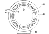
図4は、未加硫トレッドTの保持手段20を図1の矢印Y方向から見た側面図であり、その要部を模式的に示している。また、図4は、未加硫トレッドTを保持手段20により保持して、成形ドラム2上の被成形体H(図では外周を点線で示す)の外周側に配置した状態を示している。
保持手段20は、図示のように、円筒状のフレーム21と、フレーム21の下面に固定されたフレーム21の移動手段22と、フレーム21の内径部に設けられた拡縮変位可能な複数の分割保持部材30とを有する。また、保持手段20は、複数の分割保持部材30を同期して拡縮変位させて所定径位置に配置する拡縮変位手段23を有し、複数の分割保持部材30を拡径又は縮径変位させて、変位可能範囲内の任意の外径の未加硫トレッドTを保持させる。拡縮変位手段23は、例えばピストン・シリンダ機構、又は、リンク機構と駆動手段等からなり、複数の分割保持部材30を、保持する未加硫トレッドTの外径に応じて半径方向に拡縮変位させ、互いに周方向に接近及び離間させる。
FIG. 4 is a side view of the holding means 20 for the unvulcanized tread T as viewed from the direction of the arrow Y in FIG. 1 and schematically shows the main part thereof. FIG. 4 shows a state in which the unvulcanized tread T is held by the holding means 20 and arranged on the outer peripheral side of the molded body H (the outer periphery is indicated by a dotted line) on the
As shown in the figure, the holding means 20 includes a
複数の分割保持部材30は、周方向に複数に分割され、互いに端部を対向させて全体として環状をなし、予め未加硫トレッドTの外周に合わせた位置に拡径又は縮径変位して、未加硫トレッドTを囲んで周方向に沿って配置される。また、複数の分割保持部材30は、それぞれ半径方向内側の保持面(未加硫トレッドTとの対向面)を、対向する未加硫トレッドTの外周面に当接させて、未加硫トレッドTを拡径した状態で保持する。この未加硫トレッドTの保持時に、保持手段20は、複数の分割保持部材30を拡径変位させたときには、拡径変位に伴い互いに周方向に離れる分割保持部材30間の離間範囲でも、それぞれ未加硫トレッドTを保持する。そのため、保持手段20は、離間範囲保持部材(図示せず)を有し、これにより、離間範囲内の未加硫トレッドTを保持して、その位置や拡径形状を維持し、かつ、その収縮を抑制して、各範囲の伸長量や厚さのバラツキを低減し、厚さの均一性を維持している。
The plurality of divided holding
図5は、本実施形態の分割保持部材30を拡大して示す平面図であり、未加硫トレッドTの保持面側から見た3つの分割保持部材30を模式的に示している。
分割保持部材30は、図示のように、それぞれ同じ形状の矩形板状をなし、周方向(図では左右方向)の一方(図では右方)の端部に凹部31が、他方(図では左方)の端部に凸部32が形成され、周方向に沿って隣接して配置されている。凸部32は、平面視矩形状の凸片であり、分割保持部材30の端部の中央部から周方向に所定長さ突出して形成されている。一方、凹部31は、凸部32よりも僅かに大きい平面視矩形状をなし、凸部32に対応する端部の中央部に形成され、凸部32の全体を内部に収容可能になっている。また、分割保持部材30は、凹部31の幅方向(図では上下方向)の両側の部分が、凸部32と同じ大きさの平面視矩形状をなすように、凹部31と凸部32が対応して形成されている。
FIG. 5 is an enlarged plan view showing the divided holding
As shown in the figure, each of the divided holding
このように、複数の分割保持部材30は、各分割位置で隣接する分割保持部材30の一方の端部に設けられた凹部31と、他方の端部に設けられた凸部32とを有し、それらの間の本体部に加えて、凹部31を挟んだ幅方向の両側と凸部32でも、未加硫トレッドTを保持する。また、縮径変位時(図5A参照)には、凸部32が、対向する凹部31内に配置され、拡径変位(図5B参照)に伴い、分割保持部材30同士が次第に離間して、凸部32が、凹部31内から分割保持部材30間の離間範囲(図5Bの範囲R)に移動する。この離間範囲Rは、拡径変位により、隣接する分割保持部材30(凸部32を除く部分)同士が周方向に離間する範囲であり、分割保持部材30の凸部32が配置されて、その範囲Rの未加硫トレッドTを保持する。従って、ここでは、分割保持部材30の凸部32が、上記した保持手段20の離間範囲保持部材を構成している。
As described above, the plurality of divided holding
また、本実施形態では、未加硫トレッドTを吸着する複数(ここでは7つ)の吸着手段33を、各分割保持部材30の凹部31を挟んだ両側と凸部32とを含む未加硫トレッドTの保持面に配置している。複数の吸着手段33は、少なくとも凹部31を挟んだ両側と凸部32とに1つずつ配置され、分割保持部材30の保持面の全体に亘って略均等に配置される。この吸着手段33は、保持面に固定された吸盤状の吸着パッドからなり、分割保持部材30を貫通する給排気管路が接続されて、それぞれ連結された給排気手段による排気と給気に応じて、未加硫トレッドTの吸着と吸着の解除とを行う。保持手段20は、この分割保持部材30が有する複数の吸着手段33により、未加硫トレッドTの外周面を着脱可能に吸着して保持するとともに、離間範囲Rの未加硫トレッドTを、凸部32の1つの吸着手段33により保持する。
Further, in the present embodiment, a plurality (seven in this case) of adsorbing means 33 that adsorbs the unvulcanized tread T are uncured including both sides sandwiching the
加えて、保持手段20は、分割保持部材30の幅方向の中央部に1又は複数(ここでは2つ)の押付手段34を有する。押付手段34は、保持された未加硫トレッドTの幅方向の中央部を半径方向内側に向けて押すプッシャーであり、例えば、分割保持部材30の貫通孔を進退して保持面から突出する押付部材と、押付部材を進退させるピストン・シリンダ機構等からなる。保持手段20は、複数の分割保持部材30の押付手段34を同期して進退させ、保持する未加硫トレッドTを押圧する。これにより、被成形体Hの外周に対向する未加硫トレッドTの幅方向の中央部を、被成形体Hの外周に設定される所定の貼り付け位置(ここでは、タイヤ赤道面)に押し付けて圧着する。
In addition, the holding means 20 has one or a plurality of (here, two) pressing means 34 at the center in the width direction of the divided holding
ここで、未加硫トレッドTは、保持手段20により幅方向の中央部を中心に保持されるため、その幅によっては、側部が分割保持部材30から外側にはみ出すことがあり、幅が広くなるほど側部のはみ出し量も多くなる。これに伴い、未加硫トレッドTは、吸着手段33よりも幅方向外側の側部が重力により下側に向けて垂れ下がり、その状態で保持手段20が成形ドラム2側(図1参照)に移動すると、側部が被成形体H等に接近して接触することがある。そのため、タイヤ製造装置1は、支持手段40により、未加硫トレッドTの少なくとも被成形体H側(移動方向前方側)の側部を支持し、その位置を被成形体Hの外径よりも外側に位置させて、側部を被成形体Hの外径よりも大きい内径に維持する。
Here, since the unvulcanized tread T is held around the central portion in the width direction by the holding means 20, depending on the width, the side portion may protrude outward from the divided holding
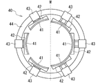
図6は、未加硫トレッドTの側部の支持手段40を図1の矢印Y方向から見た側面図であり、その要部を模式的に示している。なお、図6では、左右の中央面Mを挟んだ各側に、異なる状態の支持手段40を示しており、左側に未加硫トレッドTを支持した状態を、右側に支持を解除した状態を示している。また、図7は、図6の支持手段40の一部を拡大して示す要部断面図である。
支持手段40は、図6に示すように、未加硫トレッドTを支持する複数(ここでは6つ)の支持部材41と、各支持部材41が固定された連結部材42と、両部材41、42を未加硫トレッドTの半径方向に移動させる移動手段43と、移動手段43が取り付けられた環状部材44とを有する。また、支持手段40は、複数の支持部材41内の中央部に円形の貫通部が設けられており、その中を被成形体Hが通過可能になっている。
FIG. 6 is a side view of the support means 40 on the side of the unvulcanized tread T as viewed from the direction of the arrow Y in FIG. 1, and schematically shows the main part. In FIG. 6, the support means 40 in different states is shown on each side across the left and right central plane M, and the state where the unvulcanized tread T is supported on the left side and the support is released on the right side. Show. FIG. 7 is an enlarged cross-sectional view showing a part of the support means 40 of FIG.
As shown in FIG. 6, the support means 40 includes a plurality of (here, six)
複数の支持部材41は、未加硫トレッドTの側部の内周面に沿って当接する板状部材であり、全体として円筒状をなすように湾曲して形成され、周方向に沿って等間隔に配置される。また、支持部材41は、それぞれ連結部材42により移動手段43に連結され、同期して作動する移動手段43により同時に移動して所定の半径方向位置に配置される。移動手段43は、例えばピストン・シリンダ機構からなり、シリンダからピストンロッドを進退させて、その先端に固定した連結部材43を介して、支持部材41を半径方向に沿って移動させる。
The plurality of
支持手段40は、移動手段43により、支持部材41を未加硫トレッドTの半径方向内側から接近させ(図6の右側と図7A参照)、未加硫トレッドTの内周面に当接させる(図6の左側と図7B参照)。このようにして、支持手段40は、保持手段20が保持する未加硫トレッドTの被成形体H側の側部を支持し、その状態で保持手段20と一体に移動して、未加硫トレッドTを被成形体Hの外周側に配置する。その後、支持手段40は、支持部材41を未加硫トレッドTの側部から離して支持を解除し、環状部材44と保持手段20間に設けられた変位機構(図示せず)により、保持部材20から離れる方向(図7Aでは右方向)に変位する。これにより、タイヤ製造装置1は、支持部材41を未加硫トレッドTの幅方向外側に変位させ、保持手段20(図4参照)による未加硫トレッドTの保持を解除させて、未加硫トレッドTを被成形体Hの外周に配置する。
The support means 40 causes the moving means 43 to bring the
次に、このタイヤ製造装置1により、未加硫タイヤを成形する手順や動作、及び、タイヤ製造方法の各工程について説明する。以下のタイヤ成形の各工程は、制御手段70(図1参照)により制御して、装置各部を予め設定されたタイミングや条件で関連動作させて実行される。また、制御手段70は、保持手段20と支持手段40とを制御して、上記のように未加硫トレッドTの保持や、未加硫トレッドTの側部の支持を実行させるとともに、各手段20、40による保持や支持を解除させる。従って、制御手段70は、後述するように、未加硫タイヤの成形段階に応じて、保持手段20による未加硫トレッドTの保持を解除させる保持解除手段と、支持手段40による未加硫トレッドTの側部の支持を解除させる支持解除手段とを構成する。
Next, the procedure and operation | movement which shape | molds an unvulcanized tire with this
タイヤ製造装置1は、まず、成形ドラム2(図1参照)により被成形体Hを成形し、その中央部を膨出させる等して未加硫トレッドTの貼り付け前の形状で保持する。また、形成手段10により、ドラム12の周方向に配置された複数のセグメント13(図2参照)を変位させて所定径位置に配置し、その周りを囲む弾性バンド14の外周に帯状の未加硫トレッドTを巻き付ける。この未加硫トレッドTは、被成形体Hの外周(最大径位置の外周)の長さに対し、所定率(例えば5〜15%)短い長さでドラム12に1周巻き付け、ドラム12の外周(弾性バンド14の外周面)に、被成形体Hの外径よりも内径が小さい環状の未加硫トレッドTを形成する。続いて、複数のセグメント13を拡径変位させてドラム12を拡径(図3参照)させ、弾性バンド14を、内周面に接触するセグメント13の拡径変位に合わせて弾性変形させる。これにより、環状の未加硫トレッドTを所定率(例えば13〜17%)拡径し、その内径を被成形体Hの外径よりも大きく拡径する。次に、保持手段20により、拡径させた未加硫トレッドTを保持してドラム12から取り外す。
First, the
図8は、この未加硫トレッドTの保持に続く未加硫タイヤの製造工程を示す模式図であり、未加硫トレッドTや被成形体Hの幅方向断面の一方側と、その付近のタイヤ製造装置1の要部を抜き出して示している。
ここで、本実施形態では、拡径前の未加硫トレッドTの内径(図8AのD1)と、被成形体Hの外径(図8BのD2)との間に拡径率Vを設定し、環状の未加硫トレッドTを設定された拡径率Vに基づき拡径させる。この拡径率Vは、被成形体Hの外径D2に対する未加硫トレッドTの内径D1の比から算出(V=1−D1/D2)される。ここでは、5〜15%の拡径率Vで未加硫トレッドTを拡径させるように、被成形体Hの外径D2に対して、拡径前の未加硫トレッドTの内径D1が設定される。ただし、未加硫トレッドTは、被成形体Hを囲んで配置するため、その外径D2よりも所定径(ここでは、20mm)だけ大きい内径(図8AのD3)に拡径する。この拡径させた未加硫トレッドTを、保持手段20により外周側から保持して移動させ、被成形体Hの外周に対向させて配置する。
FIG. 8 is a schematic view showing a manufacturing process of the unvulcanized tire following the holding of the unvulcanized tread T, and one side of the cross section in the width direction of the unvulcanized tread T and the molded body H and the vicinity thereof. The main part of the
Here, in this embodiment, the diameter expansion rate V is set between the inner diameter (D1 in FIG. 8A) of the unvulcanized tread T before diameter expansion and the outer diameter (D2 in FIG. 8B) of the molded body H. Then, the diameter of the annular unvulcanized tread T is expanded based on the set diameter expansion rate V. This diameter expansion rate V is calculated from the ratio of the inner diameter D1 of the unvulcanized tread T to the outer diameter D2 of the molded body H (V = 1−D1 / D2). Here, the inner diameter D1 of the unvulcanized tread T before being expanded is larger than the outer diameter D2 of the molded body H so that the unvulcanized tread T is expanded at a diameter expansion rate V of 5 to 15%. Is set. However, since the unvulcanized tread T is disposed so as to surround the molded body H, the unvulcanized tread T is expanded to an inner diameter (D3 in FIG. 8A) larger than the outer diameter D2 by a predetermined diameter (here, 20 mm). This expanded unvulcanized tread T is held and moved from the outer peripheral side by the holding means 20, and is disposed so as to face the outer periphery of the molded body H.
配置工程では、予め、周方向に複数に分割された分割保持部材30(図8A参照)を、未加硫トレッドTの外径に応じて拡縮変位させ、ドラム12と同芯状に、未加硫トレッドTの外周側に配置する。続いて、複数の分割保持部材30により、吸着手段33を作動させて、拡径させた未加硫トレッドTを囲んで保持する。同時に、拡径変位に伴い離れる分割保持部材30間の離間範囲R(図5B参照)でも、凸部32の吸着手段33により未加硫トレッドTを保持する。次に、支持手段40により、複数の支持部材41を、保持した未加硫トレッドTの被成形体H側(移動方向前方側)の側部に当接させ、側部を支持して被成形体Hの外径D2よりも大きい内径D3に維持する。
In the arranging step, the divided holding member 30 (see FIG. 8A) divided in advance in the circumferential direction is expanded / contracted according to the outer diameter of the unvulcanized tread T, and concentrically with the
タイヤ製造装置1は、このように未加硫トレッドTを保持や支持して、上記した配置手段により両手段20、40を成形ドラム2に向けて一体に平行移動させ、未加硫トレッドTを移動させる。これにより、未加硫トレッドTを、支持手段40が支持する側部側から被成形体Hの半径方向外側を通過させて(図8B参照)、被成形体Hの外周側(半径方向外側)の所定の配置位置まで、拡径状態に維持して被成形体Hと同芯状に移動させる。また、未加硫トレッドTの内周を被成形体Hの外周に対向させるとともに、未加硫トレッドTの幅方向の中央部と被成形体Hのタイヤ赤道面の両位置を合わせて、未加硫トレッドTを被成形体Hの外周に配置する。次に、未加硫トレッドTの配置が完了した後に、支持部材41を、被成形体Hの外周に対向する未加硫トレッドTの側部から離し、支持手段40による未加硫トレッドTの側部の支持を解除する。この支持手段40による支持の解除後に、保持手段20による未加硫トレッドTの保持を解除する。
The
その際、本実施形態では、まず、各分割保持部材30に設けられた押付手段34(図8C参照)を同期して作動させ、被成形体Hの外周に対向する未加硫トレッドTの幅方向の中央部を、被成形体Hの外周に設定される所定の貼り付け位置(ここでは、タイヤ赤道面)に押し付ける。これにより、未加硫トレッドTの中央部を、周方向に沿って複数箇所で被成形体H(ここでは、螺旋状に巻き付けたコードCからなるベルトB)の外周面に圧着して貼り付け、それらの中央部同士の位置を合わせて固定する。この押付手段34による中央部の圧着後に、吸着手段33の吸着を停止し、保持手段20による未加硫トレッドTの保持を解除する。
At this time, in this embodiment, first, the pressing means 34 (see FIG. 8C) provided in each divided holding
タイヤ製造装置1は、未加硫トレッドTの保持を解除して拡径させた未加硫トレッドTを解放し、ゴムの収縮力により、未加硫トレッドTを対向する被成形体Hの外周に向けて収縮させる。これに伴い、未加硫トレッドTを、半径方向内側に収縮(縮径)させて被成形体Hの外周に向けて変形させ(図8D参照)、少なくともタイヤ赤道面付近で被成形体Hに当接させつつ、その外周に沿うように変形させる。
The
続いて、タイヤ製造装置1は、被成形体Hの外周に対向する未加硫トレッドTの保持手段20による保持を解除した後、保持手段20と支持手段40を移動させて被成形体Hから離し、成形ドラム2により被成形体Hを回転させる。次に、押圧手段3の一対の押圧ローラ3R(図8E参照)を未加硫トレッドTの外周面に押し付け、一対の押圧ローラ3Rを、未加硫トレッドTの幅方向の中央部から外側に向かって外周面に沿って移動させる。この押圧ローラ3Rにより、収縮した未加硫トレッドTを被成形体Hに押圧して、その全体をステッチングし、未加硫トレッドTを被成形体Hの外周形状に合わせて密着させる。これにより、被成形体Hの外周に未加硫トレッドTの内周を圧着して貼り付けて未加硫タイヤを成形(製造)する。その後、成形した未加硫タイヤを加硫成型して、空気入りタイヤ等の各種のタイヤが製造される。
Subsequently, the
以上説明したタイヤ成形時に、本実施形態では、被成形体Hの外径D2よりも内径D1が小さい環状の未加硫トレッドTを、被成形体Hの外径D2よりも大きい内径D3に拡径させて保持する。また、未加硫トレッドTの内周を被成形体Hの外周に対向させて未加硫トレッドTの保持を解除し、拡径させた未加硫トレッドTを、内在する収縮力により、対向する被成形体Hの外周に向けて収縮させる。そのため、環状の未加硫トレッドTを、従来のように押圧して大きく絞り込み変形させる必要なく、収縮に応じて無理なく被成形体Hの外周に沿う形状に変形させることができる。 At the time of tire formation described above, in this embodiment, an annular unvulcanized tread T having an inner diameter D1 smaller than the outer diameter D2 of the molded body H is expanded to an inner diameter D3 larger than the outer diameter D2 of the molded body H. Keep the diameter. Further, the unvulcanized tread T is opposed to the outer periphery of the molded body H to release the holding of the unvulcanized tread T, and the expanded unvulcanized tread T is opposed by the inherent shrinkage force. It shrinks toward the outer periphery of the molding H to be performed. Therefore, the annular unvulcanized tread T can be deformed into a shape along the outer periphery of the molded body H without difficulty according to the contraction without the need to press and greatly squeeze and deform as in the conventional case.
これに伴い、未加硫トレッドTを、側部の皺や起伏の発生を防止して、被成形体Hに均一に精度よく貼り付けることができる。その結果、サイド部の凹凸の発生を抑制でき、未加硫タイヤの側部に生じる厚さや外観のバラツキを低減させて均一性を高めることもできる。特に、モーターサイクル用のタイヤのように、タイヤ幅方向中央部と側部との直径差が大きいタイヤを成形するときに、押圧ローラ3Rの押圧による未加硫トレッドTの変形量を低減させて、表面の凹凸の発生を効果的に抑制できる。また、未加硫タイヤの加硫時にも、その表面の成型を容易にして問題の発生を抑制できるため、加硫後のタイヤ表面に凹凸やベアを含む外観上の問題が発生するのを抑制しつつ、タイヤの周方向に沿う厚さの均一性を高めてユニフォーミティを向上できる。
Along with this, the unvulcanized tread T can be uniformly and accurately attached to the molded body H by preventing the occurrence of wrinkles and undulations on the side portions. As a result, the occurrence of unevenness on the side portions can be suppressed, and the uniformity of the thickness can be increased by reducing the variation in thickness and appearance generated on the side portions of the unvulcanized tire. In particular, when a tire having a large diameter difference between the center part and the side part in the tire width direction, such as a tire for a motorcycle, is formed, the deformation amount of the unvulcanized tread T due to the pressing of the
従って、本実施形態によれば、未加硫タイヤの成形時に、未加硫トレッドTの幅や種類によらず、未加硫トレッドTを、被成形体Hの外周に沿うように収縮させて、表面の凹凸を抑制して被成形体Hの外周に精度よく貼り付けることができる。また、被成形体Hに貼り付けた未加硫トレッドTの周方向の均一性を高めて、タイヤのユニフォーミティを向上させることもできる。 Therefore, according to the present embodiment, when the unvulcanized tire is molded, the unvulcanized tread T is contracted along the outer periphery of the molded body H regardless of the width and type of the unvulcanized tread T. In addition, the surface irregularities can be suppressed and the surface of the molded body H can be accurately attached. Moreover, the uniformity of the circumferential direction of the unvulcanized tread T affixed to the to-be-molded body H can be improved, and the uniformity of a tire can also be improved.
更に、このタイヤ製造装置1では、未加硫トレッドTの側部を支持手段40により支持し、支持した側部側から未加硫トレッドTを被成形体Hの外周に配置するため、未加硫トレッドTの側部が被成形体Hに接触するのを確実に防止できる。これにより、上記のように、未加硫トレッドTの側部が保持手段20からはみ出して垂れ下がるときにも、未加硫トレッドTを円滑に被成形体Hの外周に配置でき、それらの不要な接触を防止して、配置作業を繰り返し正確かつ精度よく行える。同時に、1つの保持手段20により、分割保持部材30を交換することなく、幅の異なる種々の未加硫トレッドTを保持して配置できるため、タイヤ製造装置1の汎用性を高めて、かつ、作業効率を向上させることもできる。また、押付手段34により、未加硫トレッドTの中央部を被成形体Hに圧着した後に、保持手段20による未加硫トレッドTの保持を解除することで、被成形体Hに対する未加硫トレッドTのズレや変動を防止できる。その結果、未加硫トレッドTを、被成形体Hの貼り付け位置に向けて正確に収縮させて精度よく配置できる。
Further, in the
これに対し、保持手段20の複数の分割保持部材30により未加硫トレッドTを保持するとともに、分割保持部材30間の離間範囲Rで、上記のように未加硫トレッドTを保持するときには、未加硫トレッドTを周方向に沿って、より均等に保持できる。また、離間範囲Rの未加硫トレッドTを、位置を保持して拡径形状に維持し、離間範囲Rでの未加硫トレッドTの収縮を抑制できるため、未加硫トレッドTの伸長量や厚さの周方向に沿うバラツキを低減して厚さの均一性を維持できる。これに伴い、被成形体Hの外周に、未加硫トレッドTを、周方向に沿って、より均一に精度よく貼り付けることができる。同時に、1つの保持手段20により、分割保持部材30を交換することなく、外径の異なる種々の未加硫トレッドTを、厚さの均一性の低下を抑制して保持でき、タイヤ製造装置1の汎用性を高めて、かつ、作業効率を向上させることもできる。
On the other hand, when holding the unvulcanized tread T by the plurality of divided holding
その際、離間範囲Rの未加硫トレッドTは、保持手段20に分割保持部材30と異なる保持部材を設け、この保持部材により、分割保持部材30の離間時に保持するようにしてもよい。ただし、分割保持部材30の凸部32により離間範囲Rの未加硫トレッドTを保持するときには、複雑な機構や動作を要することなく、凹部31内から離間範囲Rに移動する凸部32により、分割保持部材30による保持に合わせて、未加硫トレッドTを保持できる。その結果、保持手段20やタイヤ製造装置1が複雑になるのを抑制でき、比較的簡単な構成で、離間範囲Rの保持に伴う上記した効果が得られる。また、分割保持部材30の凹部31を挟んだ両側でも未加硫トレッドTを保持すると、隣り合う分割保持部材30が互いに周方向に近い位置で未加硫トレッドTを保持するため、その離間時を含めて、未加硫トレッドTを周方向に沿って一層均等に保持できる。更に、分割保持部材20に吸着手段32を設けて、未加硫トレッドTを吸着して保持することで、未加硫トレッドTを損傷させずに、その保持と保持の解除とを円滑かつ迅速に行える。
At that time, the unvulcanized tread T in the separation range R may be held when the divided holding
ここで、このタイヤ製造装置1では、ドラム12の弾性バンド14(図3参照)を、外周面よりもセグメント13と接触する内周面の摩擦係数を小さくし、ドラム12の拡径時に、上記のように、弾性バンド14の全体をより均等に伸長させる。そのため、弾性バンド14と同様に伸長する未加硫トレッドTを厚さのバラツキを低減しつつ拡径変形させることができ、未加硫トレッドTを、厚さの周方向の均一性を一層高くした状態で、被成形体Hの外周に均一に貼り付けることができる。また、弾性バンド14の内周面に、セグメント13に対する摩擦力を低減させる表面処理を施し、或いは、内周面に外周面よりも摩擦係数が小さい弾性変形可能な低摩擦部材(例えば、伸縮可能な布)を設けることで、内周面の摩擦係数を確実に小さくできる。併せて、内周面の状態を長期に亘り同程度に維持して、拡径時におけるセグメント13との間の滑りを確実に確保できる。
Here, in the
なお、本実施形態では、未加硫トレッドTを移動させて被成形体Hの外周に対向させて配置したが、未加硫トレッドTを移動させずに、被成形体Hを未加硫トレッドTの内周側まで移動させて、それらを対向させて配置するようにしてもよい。また、未加硫トレッドTの側部は、支持手段40の支持部材41を内周面に当接させて支持する以外に、例えば、外周面を複数の吸着手段により吸着して支持する等、他の支持手段で支持してもよい。更に、未加硫トレッドTは、一種類のゴムから成形された単一ゴム部材でも、複数種類のゴムから成形された複数ゴム部材でもよく、複数ゴム部材のときには、予め帯状の複数ゴム部材を形成してドラム12に供給してもよく、ドラム12上で各ゴム部材を組み合わせて複数ゴム部材を形成してもよい。
In this embodiment, the unvulcanized tread T is moved so as to be opposed to the outer periphery of the molded body H. However, the unvulcanized tread T is moved without moving the unvulcanized tread T. You may make it move to the inner peripheral side of T, and arrange | position them so that it may oppose. Further, the side portion of the unvulcanized tread T is supported by supporting the
(未加硫タイヤの成形試験)
本発明の効果を確認するため、タイヤ製造装置1により、以上説明したように未加硫タイヤを成形して、未加硫トレッドTの伸びと厚さのバラツキや均一性を評価する試験を行った。試験では、まず、環状の未加硫トレッドTを形成したドラム12(図3参照)を拡径させて、未加硫トレッドTの内径を被成形体Hの外径よりも大きく拡径させた状態で、未加硫トレッドTの伸びを測定した。
(Molding test of unvulcanized tire)
In order to confirm the effect of the present invention, the
その際、一定の大きさの単位図形を、拡径前の未加硫トレッドTの外周面に、かつ、その幅方向中央部に周方向に沿って複数画き、未加硫トレッドTの拡径前後で各単位図形の周方向長さを測定した。これにより、拡径前に対する拡径後の未加硫トレッドTの各部の伸びを求めて、10個のセグメント13が弾性バンド14にそれぞれ接触する位置と、セグメント13の間の位置の未加硫トレッドTの伸長率を取得し、そのバラツキと均一性を評価した。また、試験では、弾性バンド14として、内周面にメリヤス編みした布を設けたゴムバンド(以下、実施例の弾性バンド14という)を使用し、外周面よりも内周面の摩擦係数を小さくして、セグメント13に対する摩擦力を低減させた。これに対し、比較例の弾性バンドとして、内周面が平らな面のゴムからなり、外周面よりも摩擦係数が大きい2種類のゴムバンドを使用し、未加硫トレッドTを拡径させて各々伸長率を測定して、実施例の弾性バンド14の結果と比較した。
At that time, a plurality of unit figures of a certain size are drawn on the outer circumferential surface of the unvulcanized tread T before diameter expansion and along the circumferential direction at the center in the width direction, and the diameter of the unvulcanized tread T is expanded. The circumferential length of each unit figure was measured before and after. Thereby, the elongation of each part of the unvulcanized tread T after the diameter expansion with respect to the diameter before the diameter expansion is obtained, and the positions where the ten
図9は、拡径後の未加硫トレッドTの伸長率を示すグラフであり、横軸が未加硫トレッドTの周方向に沿う位置(図のセグメントはセグメント13の位置、間はセグメント13の間の位置)を、縦軸が各位置の伸長率(%)を示している。
試験の結果、比較例の弾性バンド(図9A参照)では、いずれも、伸長率が小さいセグメント13の位置に対して、セグメント13の間の位置で伸長率が大きくなり、周方向に沿って伸長率に6%程度のバラツキが生じた。これに対し、実施例の弾性バンド14(図9B参照)では、セグメント13の位置とセグメント13の間の位置とで伸長率に差がなく、伸長率のバラツキが1.8%程度と低減して均一性が高くなった。これより、実施例の弾性バンド14では、比較例の弾性バンドに比べて均等に伸長し、未加硫トレッドTをより均等に伸長させて厚さのバラツキを低減でき、厚さの周方向の均一性を高くできることが分かった。
FIG. 9 is a graph showing the elongation rate of the unvulcanized tread T after the diameter expansion. The horizontal axis is a position along the circumferential direction of the unvulcanized tread T (the segment in the figure is the position of the
As a result of the test, in the elastic band of the comparative example (see FIG. 9A), the elongation rate increases at the position between the
次に、実施例の弾性バンド14で拡径させた未加硫トレッドTを保持手段20(図4、図5参照)で保持し、未加硫トレッドTを被成形体Hの外周に対向させて保持を解除した後、収縮した状態の未加硫トレッドT(図8D参照)の伸びを被成形体H上で測定した。この試験では、上記と同様に単位図形の周方向長さを測定することで、ドラム12による拡径前に対する収縮後の未加硫トレッドTの各部の伸びを求めた。これにより、周方向に沿う複数位置で、未加硫トレッドTの幅方向中央部の伸長率を取得し、そのバラツキと均一性を評価した。また、ここでは、実施例の保持手段20に、周方向に11分割した分割保持部材30を設けて、その離間範囲Rに位置する凸部32でも未加硫トレッドTを保持し、比較例の保持手段により未加硫トレッドTを保持したときと比較した。
Next, the unvulcanized tread T expanded in diameter by the
図10Aは、比較例の保持手段の要部を示す側面図であり、図10Bは、比較例の分割保持部材を拡大して示す平面図である。
比較例の保持手段80(図10A参照)には、周方向に6分割した分割保持部材81を設け、それらの半径方向内側の保持面で未加硫トレッドTを保持する。また、比較例の分割保持部材81(図10B参照)は、分割位置で直線状に分割して凹部や凸部のない矩形板状に形成し、複数の吸着手段82により未加硫トレッドTを吸着して保持する。このように、比較例の分割保持部材81は、実施例の分割保持部材30よりも少ない数に分割し、分割保持部材81同士が離れたときには、離間範囲の未加硫トレッドTを保持しないようになっている。
FIG. 10A is a side view showing the main part of the holding means of the comparative example, and FIG. 10B is an enlarged plan view showing the divided holding member of the comparative example.
The holding means 80 (see FIG. 10A) of the comparative example is provided with divided holding
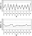
図11は、収縮後の未加硫トレッドTの伸長率を示すグラフであり、横軸が未加硫トレッドTの周方向に沿う位置、縦軸が各位置の伸長率(%)を示している。また、図11Aは、比較例の保持手段80で保持した3つの未加硫トレッドTの伸長率の変化を示し、図11Bは、実施例の保持手段20で保持した4つの未加硫トレッドTの伸長率の変化を示している。
試験の結果、比較例の保持手段80(図11A参照)では、分割保持部材81間の未加硫トレッドTが収縮するのに伴い、被成形体H上でも、収縮後の未加硫トレッドTの伸長率に周方向に沿って3.5〜5.7%程度のバラツキが生じた。また、分割保持部材81間に対応する位置(図11Aの谷部)で伸長率が小さくなり、伸長率が周方向に沿ってジグザグ状に繰り返し変化していた。
FIG. 11 is a graph showing the elongation rate of the unvulcanized tread T after shrinkage, where the horizontal axis indicates the position along the circumferential direction of the unvulcanized tread T, and the vertical axis indicates the elongation rate (%) at each position. Yes. FIG. 11A shows changes in the elongation rate of the three unvulcanized treads T held by the holding
As a result of the test, in the holding means 80 (see FIG. 11A) of the comparative example, as the unvulcanized tread T between the divided holding
これに対し、実施例の保持手段20(図11B参照)では、未加硫トレッドTの伸長率の変化が小さくなり、伸長率のバラツキが2.6〜3.2%程度と低減して均一性が高くなった。これより、実施例の保持手段20では、未加硫トレッドTを離間範囲Rでも保持して周方向に沿ってより均等に保持でき、未加硫トレッドTの伸長量や厚さの周方向に沿うバラツキを低減して、厚さの均一性を維持できることが分かった。また、未加硫トレッドTを、被成形体Hに、より均一に精度よく貼り付けられることが分かった。 On the other hand, in the holding means 20 (see FIG. 11B) of the example, the change in the elongation rate of the unvulcanized tread T is reduced, and the variation in the elongation rate is reduced to about 2.6 to 3.2% and uniform. The nature became high. Thus, in the holding means 20 of the embodiment, the unvulcanized tread T can be held even in the separation range R and can be held more evenly along the circumferential direction, and the extension amount and thickness of the unvulcanized tread T can be held in the circumferential direction. It was found that the uniformity along the thickness can be maintained by reducing the variation along the line. Further, it was found that the unvulcanized tread T can be adhered to the molded body H more uniformly and accurately.
以上の試験に加えて、タイヤ製造装置1により、3つの拡径率V(5、10、15%)で未加硫トレッドTを拡径させて被成形体Hに貼り付け、未加硫タイヤを成形してタイヤ(以下、実施品1、2、3という)を製造した。また、上記した従来のタイヤ製造方法(図13参照)により、未加硫トレッドTを収縮させずに(拡径率V=0%)、押圧して絞り込み変形させて被成形体Hの外周面に貼り付け、未加硫タイヤを成形してタイヤ(以下、従来品という)を製造した。これら実施品と従来品のトレッドの厚さを、幅方向の中央部(タイヤ赤道面)と中間部(1/4点)と端部(ハンプ部)とで、それぞれタイヤ周方向に沿って複数箇所で測定し、それらのバラツキを比較した。その際、中央部と中間部と端部とで、それぞれ厚さの最大測定値と最小測定値の差を算出して、各部における周方向の厚さのバラツキを求め、それらを比較して厚さの均一性を評価した。
In addition to the above tests, the
表1に、実施品と従来品の厚さのバラツキを示す。なお、各バラツキは、それぞれ従来品の端部のバラツキを1とした指数で表し、その値が小さいほどバラツキが小さいことを示している。また、未加硫タイヤの成形時に、従来品では未加硫トレッドTの側部に皺が発生したが、実施品1、2、3では、いずれも側部に皺が発生せずに、未加硫トレッドTが被成形体Hの外周に沿って変形した。
Table 1 shows the variation in the thickness of the implemented product and the conventional product. Each variation is represented by an index where the variation at the end of the conventional product is 1, and the smaller the value, the smaller the variation. In addition, when molding an unvulcanized tire, wrinkles occurred on the side portions of the unvulcanized tread T in the conventional product, but in the

図12は、実施品と従来品のトレッドの厚さのバラツキを示すグラフである。
図示のように、従来品に対し、実施品1、2、3では、端部のバラツキが0.8、0.6、0.6と小さくなり、均一性が高くなっていた。また、実施品1、2、3では、全体として、従来品よりもバラツキが小さくなり、周方向に沿うトレッドの厚さの均一性が高いことが分かった。特に、実施品2(拡径率V=10%)は、他の実施品1、3よりもバラツキが小さく、厚さの均一性が最も高くなることが分かった。
FIG. 12 is a graph showing variations in the thickness of the tread between the actual product and the conventional product.
As shown in the drawing, in the
続いて、これら従来品と実施品1、2、3を自動二輪車のリア側に取り付け、凹凸路面と良路面のテストコースを走行する実車試験を実施した。従来品と実施品1、2、3は、JATMA YEAR BOOK(2009、日本自動車タイヤ協会規格)で定めるタイヤサイズ190/55R17のモーターサイクル用ラジアルプライタイヤであり、内圧を250kPaに調整した。試験では、同じ条件で走行したときに、それぞれ縦振動の大きさ(タイヤのショック吸収性)を10点満点で評価した。表2に、評価結果を示す。
Subsequently, these conventional products and the
試験の結果、表2に示すように、凹凸路面でのショック吸収性は、従来品の5.5に対し、実施品1、2、3では全て6と高く、実施品1、2、3の縦振動が小さくなっていた。また、良路面でのショック吸収性も、従来品の5に対し、実施品1、2、3では6、7.5、7.3と全て高くなっていた。これより、実施品1、2、3(特に、実施品2)では、トレッドの周方向の厚さの均一性が高くなり、タイヤのユニフォーミティが向上するのに伴い、走行時の縦振動が小さくなることが分かった。
As a result of the test, as shown in Table 2, the shock absorbency on the uneven road surface is as high as 6 for the
以上の結果から、本発明により、未加硫タイヤの成形時に、未加硫トレッドTを、被成形体Hの外周に沿うように収縮させて、表面の凹凸を抑制して被成形体Hの外周に精度よく貼り付けられるとともに、被成形体Hに貼り付けた未加硫トレッドTの周方向の均一性を高めて、タイヤのユニフォーミティを向上できることが証明された。 From the above results, according to the present invention, when the unvulcanized tire is molded, the unvulcanized tread T is shrunk along the outer periphery of the molded body H, and the unevenness of the surface is suppressed to suppress the surface of the molded body H. It has been proved that the uniformity of the tire can be improved by being applied to the outer periphery with high accuracy and improving the uniformity in the circumferential direction of the unvulcanized tread T attached to the molded body H.
1・・・タイヤ製造装置、2・・・成形ドラム、3・・・押圧手段、3R・・・押圧ローラ、10・・・未加硫トレッドの形成装置、11・・・未加硫トレッドの供給手段、12・・・ドラム、13・・・セグメント、14・・・弾性バンド、20・・・保持手段、21・・・フレーム、22・・・移動手段、23・・・拡縮変位手段、30・・・分割保持部材、31・・・凹部、32・・・凸部、33・・・吸着手段、34・・・押付手段、40・・・支持手段、41・・・支持部材、42・・・連結部材、43・・・移動手段、44・・・環状部材、70・・・制御手段、71・・・MPU、72・・・ROM、73・・・RAM、H・・・被成形体、R・・・離間範囲、T・・・未加硫トレッド。
DESCRIPTION OF
Claims (5)
外周に環状の未加硫トレッドが形成される拡縮可能なドラムと、
ドラムを拡径させて、環状の未加硫トレッドを拡径させる拡径手段と、
拡径させた未加硫トレッドを保持する保持手段と、
保持手段が保持する未加硫トレッドを被成形体の外周に対向させて配置する配置手段と、
被成形体の外周に対向する未加硫トレッドの保持手段による保持を解除させる保持解除手段と、
保持手段による保持を解除した未加硫トレッドを被成形体に押圧し、被成形体の外周に圧着して貼り付ける押圧手段と、を備え、
ドラムが、ドラム周方向に配置された拡縮変位可能な複数のセグメントと、複数のセグメントを囲んで配置された弾性バンドを有し、セグメントと接触する弾性バンドの内周面とセグメントとの摩擦係数を、前記セグメントの拡径に伴う弾性バンドの拡径変形時に、セグメントに対して滑りが可能な値にしたことを特徴とするタイヤ製造装置。 A tire manufacturing apparatus for forming an unvulcanized tire by attaching an unvulcanized tread to the outer periphery of a molded body,
An expandable / contractible drum in which an annular unvulcanized tread is formed on the outer periphery;
A diameter expanding means for expanding the diameter of the drum and expanding the diameter of the annular unvulcanized tread;
Holding means for holding the unvulcanized tread expanded in diameter;
An arrangement means for arranging the unvulcanized tread held by the holding means so as to oppose the outer periphery of the molded body;
Holding release means for releasing the holding by the holding means of the unvulcanized tread facing the outer periphery of the molded body;
A pressing means for pressing the unvulcanized tread released from holding by the holding means against the molded body, and crimping and bonding to the outer periphery of the molded body,
The drum has a plurality of segments that can be expanded and contracted disposed in the circumferential direction of the drum, and an elastic band that is disposed so as to surround the plurality of segments, and a friction coefficient between the inner peripheral surface of the elastic band that contacts the segment and the segment The tire manufacturing apparatus according to claim 1, wherein the elastic band is allowed to slide with respect to the segment when the elastic band expands and deforms as the segment expands .
弾性バンドの内周面に、接触するセグメントに対する摩擦力を低減させる表面処理が施されていることを特徴とするタイヤ製造装置。 In the tire manufacturing apparatus according to claim 1,
A tire manufacturing apparatus, wherein an inner peripheral surface of an elastic band is subjected to a surface treatment for reducing a frictional force with respect to a contacting segment.
弾性バンドが、内周面に接触するセグメントに対する摩擦力を低減させる弾性変形可能な摩擦部材を有することを特徴とするタイヤ製造装置。 In the tire manufacturing apparatus according to claim 1,
Elastic band, a tire manufacturing apparatus characterized by comprising an elastically deformable friction members reduce frictional forces for the segment in contact with the inner circumferential surface.
摩擦部材が、伸縮可能な布であることを特徴とするタイヤ製造装置。 In the tire manufacturing apparatus according to claim 3,
Tire production apparatus, wherein the friction member is a stretchable fabric.
ドラムの周方向に配置された複数のセグメントを囲む弾性バンドの外周面に、被成形体の外径よりも内径が小さい環状の未加硫トレッドを形成する工程と、
複数のセグメントを拡径変位させる工程と、
弾性バンドを内周面に接触するセグメントの拡径変位に合わせて弾性変形させ、環状の未加硫トレッドの内径を被成形体の外径よりも大きく拡径する工程と、
拡径させた未加硫トレッドを保持して被成形体の外周に対向させて配置する工程と、
未加硫トレッドの保持を解除して、未加硫トレッドを対向する被成形体の外周に向けて収縮させる工程と、
収縮した未加硫トレッドを被成形体に押圧し、未加硫トレッドを被成形体の外周に圧着して貼り付ける工程と、を有し、
セグメントと接触する弾性バンドの内周面とセグメントとの摩擦係数を、前記セグメントの拡径に伴う弾性バンドの拡径変形時に、セグメントに対して滑りが可能な値にしたことを特徴とするタイヤ製造方法。 A tire manufacturing method for forming an unvulcanized tire by attaching an unvulcanized tread to the outer periphery of a molded body,
Forming an annular unvulcanized tread having an inner diameter smaller than the outer diameter of the molded body on the outer peripheral surface of the elastic band surrounding the plurality of segments arranged in the circumferential direction of the drum;
A step of expanding and displacing a plurality of segments;
A step of elastically deforming the elastic band according to the expansion displacement of the segment in contact with the inner peripheral surface, and expanding the inner diameter of the annular unvulcanized tread to be larger than the outer diameter of the molded body;
A step of holding the unvulcanized tread that has been expanded in diameter and facing the outer periphery of the molded body; and
Releasing the retention of the unvulcanized tread and shrinking the unvulcanized tread toward the outer periphery of the opposite object to be molded; and
Pressing the shrunk unvulcanized tread against the molded body, and pressing and pasting the unvulcanized tread to the outer periphery of the molded body,
The friction coefficient between the inner peripheral surface and the segments of the elastic band in contact with the segment, when expanded deformation of the elastic band associated with the diameter of the segments, characterized in that the possible slip values for segments Tire manufacturing method.
Priority Applications (1)
| Application Number | Priority Date | Filing Date | Title |
|---|---|---|---|
| JP2009198340A JP5376589B2 (en) | 2009-08-28 | 2009-08-28 | Tire manufacturing apparatus and tire manufacturing method |
Applications Claiming Priority (1)
| Application Number | Priority Date | Filing Date | Title |
|---|---|---|---|
| JP2009198340A JP5376589B2 (en) | 2009-08-28 | 2009-08-28 | Tire manufacturing apparatus and tire manufacturing method |
Publications (2)
| Publication Number | Publication Date |
|---|---|
| JP2011046164A JP2011046164A (en) | 2011-03-10 |
| JP5376589B2 true JP5376589B2 (en) | 2013-12-25 |
Family
ID=43832969
Family Applications (1)
| Application Number | Title | Priority Date | Filing Date |
|---|---|---|---|
| JP2009198340A Active JP5376589B2 (en) | 2009-08-28 | 2009-08-28 | Tire manufacturing apparatus and tire manufacturing method |
Country Status (1)
| Country | Link |
|---|---|
| JP (1) | JP5376589B2 (en) |
Families Citing this family (1)
| Publication number | Priority date | Publication date | Assignee | Title |
|---|---|---|---|---|
| JP5722051B2 (en) * | 2011-01-11 | 2015-05-20 | 株式会社ブリヂストン | Tire manufacturing apparatus and tire manufacturing method |
Family Cites Families (9)
| Publication number | Priority date | Publication date | Assignee | Title |
|---|---|---|---|---|
| JPH01249429A (en) * | 1988-03-31 | 1989-10-04 | Sumitomo Rubber Ind Ltd | Method and apparatus for molding belt-tread assembly |
| JPH0381132A (en) * | 1989-08-24 | 1991-04-05 | Bridgestone Corp | Method and apparatus for forming tire |
| JP4259704B2 (en) * | 1999-12-07 | 2009-04-30 | 横浜ゴム株式会社 | Tire molding system and molding method |
| JP4166535B2 (en) * | 2002-09-02 | 2008-10-15 | 横浜ゴム株式会社 | Method of manufacturing tire by multi-part tire molding drum and multi-part tire molding drum |
| JP2006069140A (en) * | 2004-09-06 | 2006-03-16 | Yokohama Rubber Co Ltd:The | Method of manufacturing retreaded tire for aircraft |
| JP2006346930A (en) * | 2005-06-14 | 2006-12-28 | Bridgestone Corp | Precured tread assembling method and precured tread assembling apparatus |
| JP5474445B2 (en) * | 2009-08-20 | 2014-04-16 | 株式会社ブリヂストン | Tire manufacturing method and tire manufacturing mold |
| JP5473117B2 (en) * | 2009-08-28 | 2014-04-16 | 株式会社ブリヂストン | Tire manufacturing apparatus and tire manufacturing method |
| JP5473053B2 (en) * | 2009-08-28 | 2014-04-16 | 株式会社ブリヂストン | Tire manufacturing apparatus and tire manufacturing method |
-
2009
- 2009-08-28 JP JP2009198340A patent/JP5376589B2/en active Active
Also Published As
| Publication number | Publication date |
|---|---|
| JP2011046164A (en) | 2011-03-10 |
Similar Documents
| Publication | Publication Date | Title |
|---|---|---|
| CN1772464B (en) | Pneumatic tire and producing method thereof | |
| JP4953308B2 (en) | Apparatus and method for attaching carcass reinforcing ply | |
| EP2352637B1 (en) | Process and apparatus for building tyres for vehicle wheels | |
| US10899095B2 (en) | Process and apparatus for building tyres for vehicle wheels | |
| RU2730832C2 (en) | Method and installation for tires assembly | |
| JP5473117B2 (en) | Tire manufacturing apparatus and tire manufacturing method | |
| JP5473053B2 (en) | Tire manufacturing apparatus and tire manufacturing method | |
| JP5376589B2 (en) | Tire manufacturing apparatus and tire manufacturing method | |
| JP4263755B1 (en) | Pneumatic tire manufacturing method | |
| JP4914508B2 (en) | Manufacturing method of raw tire for motorcycle | |
| CN100418746C (en) | Method for mfg. inflatable tyre | |
| US20170157873A1 (en) | Method and apparatus for assembling a tire blank | |
| JP6953983B2 (en) | Tire manufacturing method | |
| JP5116011B2 (en) | Tire manufacturing apparatus and manufacturing method | |
| US20210122127A1 (en) | Tire manufacturing method | |
| JP5536391B2 (en) | Rejuvenated tire manufacturing method and manufacturing apparatus | |
| JP5361679B2 (en) | Crimping device for tire component and tire manufacturing device | |
| JP2008207506A (en) | Tire molding method | |
| JP5056440B2 (en) | Pneumatic tire manufacturing method and pneumatic tire | |
| JP2004249496A (en) | Method and apparatus for manufacturing pneumatic tire | |
| CN109476106B (en) | Method and apparatus for building tyres for vehicle wheels | |
| US10532530B2 (en) | Device and method for producing tires | |
| JP6794664B2 (en) | Raw tire manufacturing method | |
| JP4860111B2 (en) | Tire manufacturing method and tire manufacturing apparatus used therefor | |
| IT202100032090A1 (en) | PROCESS AND LABELING SYSTEM OF A GREEN BICYCLE TIRE |
Legal Events
| Date | Code | Title | Description |
|---|---|---|---|
| A621 | Written request for application examination |
Free format text: JAPANESE INTERMEDIATE CODE: A621 Effective date: 20120828 |
|
| A977 | Report on retrieval |
Free format text: JAPANESE INTERMEDIATE CODE: A971007 Effective date: 20130724 |
|
| A131 | Notification of reasons for refusal |
Free format text: JAPANESE INTERMEDIATE CODE: A131 Effective date: 20130725 |
|
| A521 | Request for written amendment filed |
Free format text: JAPANESE INTERMEDIATE CODE: A523 Effective date: 20130830 |
|
| TRDD | Decision of grant or rejection written | ||
| A01 | Written decision to grant a patent or to grant a registration (utility model) |
Free format text: JAPANESE INTERMEDIATE CODE: A01 Effective date: 20130919 |
|
| A61 | First payment of annual fees (during grant procedure) |
Free format text: JAPANESE INTERMEDIATE CODE: A61 Effective date: 20130919 |
|
| R150 | Certificate of patent or registration of utility model |
Ref document number: 5376589 Country of ref document: JP Free format text: JAPANESE INTERMEDIATE CODE: R150 Free format text: JAPANESE INTERMEDIATE CODE: R150 |
|
| R250 | Receipt of annual fees |
Free format text: JAPANESE INTERMEDIATE CODE: R250 |
|
| R250 | Receipt of annual fees |
Free format text: JAPANESE INTERMEDIATE CODE: R250 |
|
| R250 | Receipt of annual fees |
Free format text: JAPANESE INTERMEDIATE CODE: R250 |
|
| R250 | Receipt of annual fees |
Free format text: JAPANESE INTERMEDIATE CODE: R250 |
|
| R250 | Receipt of annual fees |
Free format text: JAPANESE INTERMEDIATE CODE: R250 |
|
| R250 | Receipt of annual fees |
Free format text: JAPANESE INTERMEDIATE CODE: R250 |
|
| R250 | Receipt of annual fees |
Free format text: JAPANESE INTERMEDIATE CODE: R250 |
|
| R250 | Receipt of annual fees |
Free format text: JAPANESE INTERMEDIATE CODE: R250 |