JP5373371B2 - Control device for hybrid electric vehicle - Google Patents
Control device for hybrid electric vehicle Download PDFInfo
- Publication number
- JP5373371B2 JP5373371B2 JP2008289441A JP2008289441A JP5373371B2 JP 5373371 B2 JP5373371 B2 JP 5373371B2 JP 2008289441 A JP2008289441 A JP 2008289441A JP 2008289441 A JP2008289441 A JP 2008289441A JP 5373371 B2 JP5373371 B2 JP 5373371B2
- Authority
- JP
- Japan
- Prior art keywords
- engine
- transmission
- torque
- vehicle
- crankshaft
- Prior art date
- Legal status (The legal status is an assumption and is not a legal conclusion. Google has not performed a legal analysis and makes no representation as to the accuracy of the status listed.)
- Expired - Fee Related
Links
Images


Classifications
-
- B—PERFORMING OPERATIONS; TRANSPORTING
- B60—VEHICLES IN GENERAL
- B60K—ARRANGEMENT OR MOUNTING OF PROPULSION UNITS OR OF TRANSMISSIONS IN VEHICLES; ARRANGEMENT OR MOUNTING OF PLURAL DIVERSE PRIME-MOVERS IN VEHICLES; AUXILIARY DRIVES FOR VEHICLES; INSTRUMENTATION OR DASHBOARDS FOR VEHICLES; ARRANGEMENTS IN CONNECTION WITH COOLING, AIR INTAKE, GAS EXHAUST OR FUEL SUPPLY OF PROPULSION UNITS IN VEHICLES
- B60K6/00—Arrangement or mounting of plural diverse prime-movers for mutual or common propulsion, e.g. hybrid propulsion systems comprising electric motors and internal combustion engines ; Control systems therefor, i.e. systems controlling two or more prime movers, or controlling one of these prime movers and any of the transmission, drive or drive units Informative references: mechanical gearings with secondary electric drive F16H3/72; arrangements for handling mechanical energy structurally associated with the dynamo-electric machine H02K7/00; machines comprising structurally interrelated motor and generator parts H02K51/00; dynamo-electric machines not otherwise provided for in H02K see H02K99/00
- B60K6/20—Arrangement or mounting of plural diverse prime-movers for mutual or common propulsion, e.g. hybrid propulsion systems comprising electric motors and internal combustion engines ; Control systems therefor, i.e. systems controlling two or more prime movers, or controlling one of these prime movers and any of the transmission, drive or drive units Informative references: mechanical gearings with secondary electric drive F16H3/72; arrangements for handling mechanical energy structurally associated with the dynamo-electric machine H02K7/00; machines comprising structurally interrelated motor and generator parts H02K51/00; dynamo-electric machines not otherwise provided for in H02K see H02K99/00 the prime-movers consisting of electric motors and internal combustion engines, e.g. HEVs
- B60K6/22—Arrangement or mounting of plural diverse prime-movers for mutual or common propulsion, e.g. hybrid propulsion systems comprising electric motors and internal combustion engines ; Control systems therefor, i.e. systems controlling two or more prime movers, or controlling one of these prime movers and any of the transmission, drive or drive units Informative references: mechanical gearings with secondary electric drive F16H3/72; arrangements for handling mechanical energy structurally associated with the dynamo-electric machine H02K7/00; machines comprising structurally interrelated motor and generator parts H02K51/00; dynamo-electric machines not otherwise provided for in H02K see H02K99/00 the prime-movers consisting of electric motors and internal combustion engines, e.g. HEVs characterised by apparatus, components or means specially adapted for HEVs
- B60K6/38—Arrangement or mounting of plural diverse prime-movers for mutual or common propulsion, e.g. hybrid propulsion systems comprising electric motors and internal combustion engines ; Control systems therefor, i.e. systems controlling two or more prime movers, or controlling one of these prime movers and any of the transmission, drive or drive units Informative references: mechanical gearings with secondary electric drive F16H3/72; arrangements for handling mechanical energy structurally associated with the dynamo-electric machine H02K7/00; machines comprising structurally interrelated motor and generator parts H02K51/00; dynamo-electric machines not otherwise provided for in H02K see H02K99/00 the prime-movers consisting of electric motors and internal combustion engines, e.g. HEVs characterised by apparatus, components or means specially adapted for HEVs characterised by the driveline clutches
-
- B—PERFORMING OPERATIONS; TRANSPORTING
- B60—VEHICLES IN GENERAL
- B60W—CONJOINT CONTROL OF VEHICLE SUB-UNITS OF DIFFERENT TYPE OR DIFFERENT FUNCTION; CONTROL SYSTEMS SPECIALLY ADAPTED FOR HYBRID VEHICLES; ROAD VEHICLE DRIVE CONTROL SYSTEMS FOR PURPOSES NOT RELATED TO THE CONTROL OF A PARTICULAR SUB-UNIT
- B60W20/00—Control systems specially adapted for hybrid vehicles
- B60W20/10—Controlling the power contribution of each of the prime movers to meet required power demand
-
- B—PERFORMING OPERATIONS; TRANSPORTING
- B60—VEHICLES IN GENERAL
- B60K—ARRANGEMENT OR MOUNTING OF PROPULSION UNITS OR OF TRANSMISSIONS IN VEHICLES; ARRANGEMENT OR MOUNTING OF PLURAL DIVERSE PRIME-MOVERS IN VEHICLES; AUXILIARY DRIVES FOR VEHICLES; INSTRUMENTATION OR DASHBOARDS FOR VEHICLES; ARRANGEMENTS IN CONNECTION WITH COOLING, AIR INTAKE, GAS EXHAUST OR FUEL SUPPLY OF PROPULSION UNITS IN VEHICLES
- B60K6/00—Arrangement or mounting of plural diverse prime-movers for mutual or common propulsion, e.g. hybrid propulsion systems comprising electric motors and internal combustion engines ; Control systems therefor, i.e. systems controlling two or more prime movers, or controlling one of these prime movers and any of the transmission, drive or drive units Informative references: mechanical gearings with secondary electric drive F16H3/72; arrangements for handling mechanical energy structurally associated with the dynamo-electric machine H02K7/00; machines comprising structurally interrelated motor and generator parts H02K51/00; dynamo-electric machines not otherwise provided for in H02K see H02K99/00
- B60K6/20—Arrangement or mounting of plural diverse prime-movers for mutual or common propulsion, e.g. hybrid propulsion systems comprising electric motors and internal combustion engines ; Control systems therefor, i.e. systems controlling two or more prime movers, or controlling one of these prime movers and any of the transmission, drive or drive units Informative references: mechanical gearings with secondary electric drive F16H3/72; arrangements for handling mechanical energy structurally associated with the dynamo-electric machine H02K7/00; machines comprising structurally interrelated motor and generator parts H02K51/00; dynamo-electric machines not otherwise provided for in H02K see H02K99/00 the prime-movers consisting of electric motors and internal combustion engines, e.g. HEVs
- B60K6/42—Arrangement or mounting of plural diverse prime-movers for mutual or common propulsion, e.g. hybrid propulsion systems comprising electric motors and internal combustion engines ; Control systems therefor, i.e. systems controlling two or more prime movers, or controlling one of these prime movers and any of the transmission, drive or drive units Informative references: mechanical gearings with secondary electric drive F16H3/72; arrangements for handling mechanical energy structurally associated with the dynamo-electric machine H02K7/00; machines comprising structurally interrelated motor and generator parts H02K51/00; dynamo-electric machines not otherwise provided for in H02K see H02K99/00 the prime-movers consisting of electric motors and internal combustion engines, e.g. HEVs characterised by the architecture of the hybrid electric vehicle
- B60K6/44—Series-parallel type
- B60K6/442—Series-parallel switching type
-
- B—PERFORMING OPERATIONS; TRANSPORTING
- B60—VEHICLES IN GENERAL
- B60K—ARRANGEMENT OR MOUNTING OF PROPULSION UNITS OR OF TRANSMISSIONS IN VEHICLES; ARRANGEMENT OR MOUNTING OF PLURAL DIVERSE PRIME-MOVERS IN VEHICLES; AUXILIARY DRIVES FOR VEHICLES; INSTRUMENTATION OR DASHBOARDS FOR VEHICLES; ARRANGEMENTS IN CONNECTION WITH COOLING, AIR INTAKE, GAS EXHAUST OR FUEL SUPPLY OF PROPULSION UNITS IN VEHICLES
- B60K6/00—Arrangement or mounting of plural diverse prime-movers for mutual or common propulsion, e.g. hybrid propulsion systems comprising electric motors and internal combustion engines ; Control systems therefor, i.e. systems controlling two or more prime movers, or controlling one of these prime movers and any of the transmission, drive or drive units Informative references: mechanical gearings with secondary electric drive F16H3/72; arrangements for handling mechanical energy structurally associated with the dynamo-electric machine H02K7/00; machines comprising structurally interrelated motor and generator parts H02K51/00; dynamo-electric machines not otherwise provided for in H02K see H02K99/00
- B60K6/20—Arrangement or mounting of plural diverse prime-movers for mutual or common propulsion, e.g. hybrid propulsion systems comprising electric motors and internal combustion engines ; Control systems therefor, i.e. systems controlling two or more prime movers, or controlling one of these prime movers and any of the transmission, drive or drive units Informative references: mechanical gearings with secondary electric drive F16H3/72; arrangements for handling mechanical energy structurally associated with the dynamo-electric machine H02K7/00; machines comprising structurally interrelated motor and generator parts H02K51/00; dynamo-electric machines not otherwise provided for in H02K see H02K99/00 the prime-movers consisting of electric motors and internal combustion engines, e.g. HEVs
- B60K6/42—Arrangement or mounting of plural diverse prime-movers for mutual or common propulsion, e.g. hybrid propulsion systems comprising electric motors and internal combustion engines ; Control systems therefor, i.e. systems controlling two or more prime movers, or controlling one of these prime movers and any of the transmission, drive or drive units Informative references: mechanical gearings with secondary electric drive F16H3/72; arrangements for handling mechanical energy structurally associated with the dynamo-electric machine H02K7/00; machines comprising structurally interrelated motor and generator parts H02K51/00; dynamo-electric machines not otherwise provided for in H02K see H02K99/00 the prime-movers consisting of electric motors and internal combustion engines, e.g. HEVs characterised by the architecture of the hybrid electric vehicle
- B60K6/48—Parallel type
- B60K6/485—Motor-assist type
-
- B—PERFORMING OPERATIONS; TRANSPORTING
- B60—VEHICLES IN GENERAL
- B60W—CONJOINT CONTROL OF VEHICLE SUB-UNITS OF DIFFERENT TYPE OR DIFFERENT FUNCTION; CONTROL SYSTEMS SPECIALLY ADAPTED FOR HYBRID VEHICLES; ROAD VEHICLE DRIVE CONTROL SYSTEMS FOR PURPOSES NOT RELATED TO THE CONTROL OF A PARTICULAR SUB-UNIT
- B60W10/00—Conjoint control of vehicle sub-units of different type or different function
- B60W10/02—Conjoint control of vehicle sub-units of different type or different function including control of driveline clutches
-
- B—PERFORMING OPERATIONS; TRANSPORTING
- B60—VEHICLES IN GENERAL
- B60W—CONJOINT CONTROL OF VEHICLE SUB-UNITS OF DIFFERENT TYPE OR DIFFERENT FUNCTION; CONTROL SYSTEMS SPECIALLY ADAPTED FOR HYBRID VEHICLES; ROAD VEHICLE DRIVE CONTROL SYSTEMS FOR PURPOSES NOT RELATED TO THE CONTROL OF A PARTICULAR SUB-UNIT
- B60W10/00—Conjoint control of vehicle sub-units of different type or different function
- B60W10/04—Conjoint control of vehicle sub-units of different type or different function including control of propulsion units
- B60W10/06—Conjoint control of vehicle sub-units of different type or different function including control of propulsion units including control of combustion engines
-
- B—PERFORMING OPERATIONS; TRANSPORTING
- B60—VEHICLES IN GENERAL
- B60W—CONJOINT CONTROL OF VEHICLE SUB-UNITS OF DIFFERENT TYPE OR DIFFERENT FUNCTION; CONTROL SYSTEMS SPECIALLY ADAPTED FOR HYBRID VEHICLES; ROAD VEHICLE DRIVE CONTROL SYSTEMS FOR PURPOSES NOT RELATED TO THE CONTROL OF A PARTICULAR SUB-UNIT
- B60W10/00—Conjoint control of vehicle sub-units of different type or different function
- B60W10/04—Conjoint control of vehicle sub-units of different type or different function including control of propulsion units
- B60W10/08—Conjoint control of vehicle sub-units of different type or different function including control of propulsion units including control of electric propulsion units, e.g. motors or generators
-
- B—PERFORMING OPERATIONS; TRANSPORTING
- B60—VEHICLES IN GENERAL
- B60W—CONJOINT CONTROL OF VEHICLE SUB-UNITS OF DIFFERENT TYPE OR DIFFERENT FUNCTION; CONTROL SYSTEMS SPECIALLY ADAPTED FOR HYBRID VEHICLES; ROAD VEHICLE DRIVE CONTROL SYSTEMS FOR PURPOSES NOT RELATED TO THE CONTROL OF A PARTICULAR SUB-UNIT
- B60W20/00—Control systems specially adapted for hybrid vehicles
-
- B—PERFORMING OPERATIONS; TRANSPORTING
- B60—VEHICLES IN GENERAL
- B60K—ARRANGEMENT OR MOUNTING OF PROPULSION UNITS OR OF TRANSMISSIONS IN VEHICLES; ARRANGEMENT OR MOUNTING OF PLURAL DIVERSE PRIME-MOVERS IN VEHICLES; AUXILIARY DRIVES FOR VEHICLES; INSTRUMENTATION OR DASHBOARDS FOR VEHICLES; ARRANGEMENTS IN CONNECTION WITH COOLING, AIR INTAKE, GAS EXHAUST OR FUEL SUPPLY OF PROPULSION UNITS IN VEHICLES
- B60K1/00—Arrangement or mounting of electrical propulsion units
- B60K1/02—Arrangement or mounting of electrical propulsion units comprising more than one electric motor
-
- B—PERFORMING OPERATIONS; TRANSPORTING
- B60—VEHICLES IN GENERAL
- B60L—PROPULSION OF ELECTRICALLY-PROPELLED VEHICLES; SUPPLYING ELECTRIC POWER FOR AUXILIARY EQUIPMENT OF ELECTRICALLY-PROPELLED VEHICLES; ELECTRODYNAMIC BRAKE SYSTEMS FOR VEHICLES IN GENERAL; MAGNETIC SUSPENSION OR LEVITATION FOR VEHICLES; MONITORING OPERATING VARIABLES OF ELECTRICALLY-PROPELLED VEHICLES; ELECTRIC SAFETY DEVICES FOR ELECTRICALLY-PROPELLED VEHICLES
- B60L2240/00—Control parameters of input or output; Target parameters
- B60L2240/40—Drive Train control parameters
- B60L2240/48—Drive Train control parameters related to transmissions
- B60L2240/486—Operating parameters
-
- B—PERFORMING OPERATIONS; TRANSPORTING
- B60—VEHICLES IN GENERAL
- B60W—CONJOINT CONTROL OF VEHICLE SUB-UNITS OF DIFFERENT TYPE OR DIFFERENT FUNCTION; CONTROL SYSTEMS SPECIALLY ADAPTED FOR HYBRID VEHICLES; ROAD VEHICLE DRIVE CONTROL SYSTEMS FOR PURPOSES NOT RELATED TO THE CONTROL OF A PARTICULAR SUB-UNIT
- B60W2520/00—Input parameters relating to overall vehicle dynamics
- B60W2520/10—Longitudinal speed
-
- B—PERFORMING OPERATIONS; TRANSPORTING
- B60—VEHICLES IN GENERAL
- B60W—CONJOINT CONTROL OF VEHICLE SUB-UNITS OF DIFFERENT TYPE OR DIFFERENT FUNCTION; CONTROL SYSTEMS SPECIALLY ADAPTED FOR HYBRID VEHICLES; ROAD VEHICLE DRIVE CONTROL SYSTEMS FOR PURPOSES NOT RELATED TO THE CONTROL OF A PARTICULAR SUB-UNIT
- B60W2540/00—Input parameters relating to occupants
- B60W2540/16—Ratio selector position
-
- B—PERFORMING OPERATIONS; TRANSPORTING
- B60—VEHICLES IN GENERAL
- B60W—CONJOINT CONTROL OF VEHICLE SUB-UNITS OF DIFFERENT TYPE OR DIFFERENT FUNCTION; CONTROL SYSTEMS SPECIALLY ADAPTED FOR HYBRID VEHICLES; ROAD VEHICLE DRIVE CONTROL SYSTEMS FOR PURPOSES NOT RELATED TO THE CONTROL OF A PARTICULAR SUB-UNIT
- B60W2710/00—Output or target parameters relating to a particular sub-units
- B60W2710/06—Combustion engines, Gas turbines
- B60W2710/0644—Engine speed
-
- B—PERFORMING OPERATIONS; TRANSPORTING
- B60—VEHICLES IN GENERAL
- B60W—CONJOINT CONTROL OF VEHICLE SUB-UNITS OF DIFFERENT TYPE OR DIFFERENT FUNCTION; CONTROL SYSTEMS SPECIALLY ADAPTED FOR HYBRID VEHICLES; ROAD VEHICLE DRIVE CONTROL SYSTEMS FOR PURPOSES NOT RELATED TO THE CONTROL OF A PARTICULAR SUB-UNIT
- B60W2710/00—Output or target parameters relating to a particular sub-units
- B60W2710/10—Change speed gearings
- B60W2710/1061—Output power
-
- B—PERFORMING OPERATIONS; TRANSPORTING
- B60—VEHICLES IN GENERAL
- B60Y—INDEXING SCHEME RELATING TO ASPECTS CROSS-CUTTING VEHICLE TECHNOLOGY
- B60Y2400/00—Special features of vehicle units
- B60Y2400/42—Clutches or brakes
- B60Y2400/428—Double clutch arrangements; Dual clutches
-
- Y—GENERAL TAGGING OF NEW TECHNOLOGICAL DEVELOPMENTS; GENERAL TAGGING OF CROSS-SECTIONAL TECHNOLOGIES SPANNING OVER SEVERAL SECTIONS OF THE IPC; TECHNICAL SUBJECTS COVERED BY FORMER USPC CROSS-REFERENCE ART COLLECTIONS [XRACs] AND DIGESTS
- Y02—TECHNOLOGIES OR APPLICATIONS FOR MITIGATION OR ADAPTATION AGAINST CLIMATE CHANGE
- Y02T—CLIMATE CHANGE MITIGATION TECHNOLOGIES RELATED TO TRANSPORTATION
- Y02T10/00—Road transport of goods or passengers
- Y02T10/60—Other road transportation technologies with climate change mitigation effect
- Y02T10/62—Hybrid vehicles
Landscapes
- Engineering & Computer Science (AREA)
- Chemical & Material Sciences (AREA)
- Combustion & Propulsion (AREA)
- Transportation (AREA)
- Mechanical Engineering (AREA)
- Automation & Control Theory (AREA)
- Hybrid Electric Vehicles (AREA)
- Control Of Vehicle Engines Or Engines For Specific Uses (AREA)
- Control Of Transmission Device (AREA)
- Electric Propulsion And Braking For Vehicles (AREA)
Description
本発明は、ハイブリッド電気自動車の制御装置に関連する。 The present invention relates to a control device for a hybrid electric vehicle.
ハイブリッド電気自動車(HEV)は、内燃機関(エンジン)によって生成された機械的動力及び電気モーターによって生成された電気的動力を用いて動く。HEVは、一般的な自動車に比べて、燃料経済性を改善し得る。HEVにおいて燃料経済性を改善する技術の一つは、エンジンが自動車を駆動する必要がない状況において、エンジンを停止することにある。このような状況においては、電気モータが、自動車を駆動すべく電気的動力を供給する。エンジンは、その後、必要とされるときに始動する。自動車が電気モータによる電気的動力で駆動されているときに、エンジンを始動すると、自動車の動力伝達系に顕著なトルク変動が生じる場合がある。 A hybrid electric vehicle (HEV) operates using mechanical power generated by an internal combustion engine (engine) and electric power generated by an electric motor. HEV can improve fuel economy compared to general automobiles. One technique for improving fuel economy in HEV is to shut down the engine in situations where the engine does not need to drive the vehicle. In such a situation, the electric motor provides electrical power to drive the automobile. The engine is then started when needed. If the engine is started when the automobile is driven by electric power from an electric motor, significant torque fluctuation may occur in the power transmission system of the automobile.
自動車におけるエンジン始動を制御する種々の方法が知られている。特許文献1には、そのようなエンジン始動の制御方法の例が記載されている。特許文献1においては、エンジンがどの程度スムーズに始動する必要があるのかを判定するために、スムーズ度係数が算出される。エンジン動作変数(operating variable)が、選択された車両運転状態に適するように(算出された)スムーズ度係数に基づいて、エンジン始動イベントにおけるエンジン動作のスムーズ度を調節する。
Various methods are known for controlling engine start in a motor vehicle.
また、特許文献2にも、そのようなエンジン始動の制御方法の例が記載されている。特許文献2においては、自動車は、モータ/ジェネレータと、エンジンとモータ/ジェネレータとの間に配置された切断クラッチと、モータ/ジェネレータと駆動輪との間に配置された変速機とを備える。その変速機は、モータ/ジェネレータと駆動輪との間でトルクを伝達すべく、選択的に締結可能な入力クラッチを含む。エンジン始動が要求されるとき、モータ/ジェネレータが作動され、そして多くの車両パラメータに基づいてエンジンの始動モードが決定される。エンジン始動時に駆動輪をエンジンから(トルク伝達に関して)少なくとも部分的に分離すべく、変速機の入力クラッチが半解放される。その後、切断クラッチが締結され、エンジンに燃料が供給されて、エンジンによるトルクが生成される。
特許文献1及び特許文献2は、各々エンジン制御又はクラッチ制御によってトルク変動を抑制しようとするものであるため、その制御応答性が劣り、トルク変動を有効に抑制することが不可能である。本発明は、このような問題に鑑みて、電動運転(モード)から(エンジン運転モードへ)の移行時に、駆動輪におけるトルク変動を有効に抑制し得る(すなわち、スムーズな移行を可能とし得る)ハイブリッド電気自動車の制御装置を提供することを目的とする。
Since
ハイブリッド電気自動車を駆動すべく、機械的動力が用いられ得る。クランクシャフトの目標回転速度が設定され、電気機械は、エンジンのクランクシャフトがその目標回転速度にて回転するように作動する。クランクシャフトと駆動輪との間の機械的経路が、それらの間で変速機を介して機械的動力を伝達すべく、選択的に形成される。その後、機械的動力は、自動車を駆動するのに使用される。 Mechanical power can be used to drive a hybrid electric vehicle. A target rotational speed of the crankshaft is set, and the electric machine operates so that the engine crankshaft rotates at the target rotational speed. A mechanical path between the crankshaft and the drive wheels is selectively formed to transmit mechanical power between them via the transmission. The mechanical power is then used to drive the automobile.
ニュートラル状態に移行する、又は、ニュートラル状態から抜け出すときの、ハイブリッド電気自動車(HEV)の電気モータ及び変速機の制御ストラテジーが記載されている。1つの例において、エンジンの運転効率が悪い状態のときにはエンジンが停止される。電動アクスル駆動装置が、(前輪及び/又は後輪の)アクスルに連結され、トルクを直接的に駆動輪に供給し得る。エンジンが停止するときに、電動運転(エンジンを停止した上で、電動アクスル駆動装置のみによって自動車を駆動)しているときに回転損失及びポンプ損失が生じないように、変速機は、ドライブ・ギア(変速ギア)からニュートラル・ギアに移行(シフト)することになる。また、エンジンのクランクシャフトは所望の回転速度に回転させられると共に、変速機はニュートラル・ギアからシフト・スケジュールに基づく適切な変速ギアに移行(シフト)することになる。変速機の目標入力回転速度は、同期速度にオフセット値を加えた速度に指令される。このオフセット値は、プラスの値となる場合も、マイナスの値となる場合もある。これによって、電動運転から(エンジン運転へ)のスムーズな移行(離脱)を確実に行うことが可能になる。 A control strategy for an electric motor and transmission of a hybrid electric vehicle (HEV) when entering or exiting the neutral state is described. In one example, the engine is stopped when the operating efficiency of the engine is poor. An electric axle drive can be connected to the axle (front and / or rear) and supply torque directly to the drive wheels. When the engine is stopped, the transmission is connected to the drive gear so that rotation loss and pump loss do not occur when the vehicle is electrically operated (the vehicle is driven only by the electric axle drive device after the engine is stopped). (Shift gear) will shift (shift) from neutral gear. In addition, the crankshaft of the engine is rotated to a desired rotational speed, and the transmission is shifted (shifted) from the neutral gear to an appropriate transmission gear based on the shift schedule. The target input rotational speed of the transmission is commanded to a speed obtained by adding an offset value to the synchronous speed. This offset value may be a positive value or a negative value. This makes it possible to reliably perform a smooth transition (disengagement) from electric operation (to engine operation).
図1に示す例示的な後輪駆動方式のHEVシステム10は、エンジン12と、クランク一体型のスタータ/ジェネレータ(CISG)14と、変速機16と、制御器34とを備えている。それ以外の車両構成も実施可能である。一例として、前輪駆動方式のHEVシステムが、エンジンと、ベルト一体型のスタータ/ジェネレータと、変速機とを含む場合もある。
The exemplary rear wheel
エンジン12は、クランクシャフト18を有している。CISG14は、クランクシャフト18に機械的に連結される。制御器34は、詳しくは後述するが、自動車を駆動するのに電気的動力を使用し、且つ、自動車を駆動するのに機械的動力を使用すべく、クランクシャフト18の目標回転速度を設定するように構成されている。
The
また、HEVシステム10は、電動リア・アクスル駆動装置(ERAD)20と、一対の駆動輪22及び24とを備えている。ERAD20は、自動車を電動運転(エンジン12を停止した上で、ERAD20のみによって自動車を駆動)しているとき、及び、自動車を加速運転しているときに、トルクを駆動輪22及び24に供給する。また、ERAD20は、回生制動を行ない、駆動輪22及び24からエネルギーを回収する。
The
変速機16は、変速機入力部25と、トルク・コンバータ(不図示)と、クラッチ入力軸26と、出力軸28とを含んでいる。クラッチ入力軸26は、トルク・コンバータ、変速機入力部25及びCISG14を介して、エンジン12に機械的に連結される。出力軸28は、ERAD20に機械的に連結される。また、変速機16は、第1クラッチ30と第2クラッチ32とを含む。クラッチ30及び32は、選択的に締結され、変速機16の変速状態を変更する。一例として、クラッチ30及び32が締結解除されて、変速機16をニュートラル・ギアに変速する場合がある。別の例として、クラッチ30及び32は(協働して、又は、単独で)締結され、変速機16を所望の変速ギアにシフトする場合もある。他の例においては、変速機16は、単一のクラッチを含む場合があり、或いは、2つ以上のクラッチを含む場合もある。
The
1つ又は複数の制御器34(例えば自動車システム制御器)が、エンジン12、CISG14、変速機16及びERAD20と通信し、それらの動作を制御する。一例として、制御器34が、変速機16のクラッチ30及び32に、作動コマンドを送信する場合がある。別の例として、制御器34が、ERAD20のトルクを低減させると共にエンジンのトルクを増大させるコマンドを送信する場合もある。さらに別の例として、制御器34が、車速、変速機16の所望変速ギア及びオフセット値に基づいて、クランクシャフト18の目標回転速度を決定して、ERAD20からエンジン12への動力源のスムーズな移行を達成する場合もある。
One or more controllers 34 (eg, automotive system controllers) communicate with the
<発進時のエンジンの回転始動>
ERAD20は、電気的動力を提供し得る。変速機16は、自動車を電動運転しているときには、それに伴って生じる回転損失及びポンプ損失を回避すべく、ニュートラル・ギア(すなわち、ニュートラル状態)に設定されている。運転者がアクセル・ペダル(不図示)を踏んだときには、エンジン12が運転者の動力要求を満たすのに必要とされるならば、エンジンの回転が始動され、エンジンの回転が上昇することになる。このとき、変速機16は、ニュートラル・ギアから所望変速ギアにシフトすることが必要となる。自動車は、電動運転からのスムーズな移行を確実に行なうためには、略同一の加速度で加速し続ける必要がある。変速機入力部25(及びクラッチ入力軸26)の目標回転速度は、このスムーズな移行を達成すべく、同期速度よりもプラス方向にオフセットされる。
<Starting engine rotation at start-up>
The ERAD 20 may provide electrical power. The
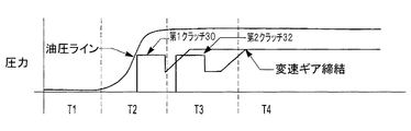
図2〜5を参照して、エンジン12を始動した後、ERAD20からエンジン12に駆動輪トルクを伝達するストラテジー制御について説明する。発進時のエンジンの回転始動イベントは、四つの時間間隔T1、T2、T3、及びT4に区分されている。T1においては、自動車は、運転者の動力要求に応じて、僅かに加速している(図5参照)。変速機16はニュートラル・ギアとされていて、これにより、クラッチ入力軸26の回転速度は実質的にゼロとなっている(図2参照)。変速機16及びクラッチ30,32に油圧を供給する油圧ライン(不図示)における圧力は低い(図3参照)。自動車がERAD20によって電気的に駆動されるため、CISG14、エンジン12及び出力軸28から供給されるトルクは低いものの、ERAD20から供給されるトルクは高い(図4参照)。
With reference to FIGS. 2 to 5, strategy control for transmitting driving wheel torque from the
T2においては、運転者による動力要求が、ERAD20及び/又はバッテリ(不図示)の動力限界値を上回る。CISG14は、エンジン12を速度制御しながら始動するように指令される(図4参照)。CISG14は、エンジン12における静止摩擦力、慣性力、熱損失、及びポンプ損失に打ち勝つのに十分なトルクを生成する。クランクシャフト18は、回転しているものの、如何なるプラス方向のトルクも伝達していないため、エンジン12のトルクは、これらの静止摩擦力、慣性力、熱損失及びポンプ損失によって低下する。クラッチ入力軸26の回転速度は、増加し始める(図2参照)。変速機16及び/又は補助オイル・ポンプ(不図示)に入力されるCISG14の回転によって、変速ギアの締結に備えて第1クラッチ30の作動を開始すべく、油圧ラインに圧力が供給される(図3参照)。
In T 2, power demand by the driver exceeds the power limit value of ERAD20 and / or battery (not shown). The
T3においては、エンジン12はトルク制御され、エンジンのトルクは、T3の初期段階においてCISG14のトルク値まで増加する(図4参照)。エンジン12はトルク制御され、エンジンのトルクがある変化率で増大する。CISG14は速度制御されているので、エンジンのトルクが増大する結果として、CISG14のトルクは(エンジン12のトルクの変化率と)同様の変化率で低下する。そのため、エンジン始動は、CISGのトルク低下によって判定され得る。エンジン始動が判定されると、変速機入力部25は速度制御され続け、変速機入力部25(及びクラッチ入力軸26)の回転速度が変速機16の同期速度に対して正のオフセット値を加えた速度となるように指令される。同期速度は、アクセル・ペダルの入力値、車速及び変速機16の変速比に基づいて決定される。変速機入力部25(及びクラッチ入力軸26)の回転速度を、目標変速ギアにおける同期速度に一致させることによって、ニュートラル・ギアから該目標変速ギアにシフトするときに、自動車のスムーズな加速が確実に達成され得る(図2参照)。正のオフセット値は、クラッチ30,32が締結するときに、動力伝達系におけるトルク反転を防止するように設定される。そのオフセット値は、自動車の設計検討に応じて変更される場合がある。
In T 3, the
T4においては、クラッチ30,32がロックされ、ニュートラル状態から締結状態への移行が完了する(図3参照)。クラッチ30,32の作動は、指令された変速ギアについてのシフト・スケジュールから判定される(図3参照)。エンジンのトルクは、変速機16が完全に締結されるので、増加し得る(図4参照)。エンジンのトルクは、駆動輪22,24のトルクを一定に維持するために、ERADのトルクの低減と略等しい変化率で増大する。
In T 4, the clutch 30, 32 is locked, the transition from the neutral state to the engaged state is completed (see FIG. 3). The operation of the
<減速時のエンジンの回転上昇>
惰性運転等の減速状態においては、エンジン12は停止され、回生制動によってエネルギーが回収され得る。ただし、バッテリ(不図示)の充電状態が高い場合には、バッテリの過充電を防止すべく、エンジンの回転を上昇させることになる。このとき、変速機16は、ニュートラル・ギアから所望の変速ギアにシフトする必要がある。自動車は、エンジンの回転上昇へのスムーズな移行を確実に行なうために、略同一の減速度で減速し続ける必要がある。変速機入力部25(及びクラッチ入力軸26)の目標回転速度は、このスムーズな移行を達成すべく、同期速度よりもマイナス方向にオフセットされる。
<Increased engine speed during deceleration>
In a deceleration state such as coasting, the
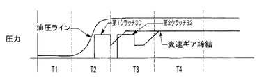
図6〜図9を参照して、回生制動中にエンジン12の回転を上昇させるストラテジー制御について説明する。減速時のエンジンの回転上昇イベントは、四つの時間間隔T1、T2、T3、及びT4に区分されている。
The strategy control for increasing the rotation of the
T1においては、自動車は減速し、ERAD20は回生制動モードとなる(図9参照)。その結果として、ERADのトルクはマイナスの値となる(図8参照)。 In T 1, vehicle decelerates, ERAD20 becomes regenerative braking mode (see FIG. 9). As a result, the ERAD torque has a negative value (see FIG. 8).
T2においては、CISG14は、エンジン12の回転を速度制御しながら上昇させるように指令される(図8参照)。CISG14は、エンジン12における静止摩擦力、慣性力、熱損失及びポンプ損失に打ち勝つのに十分なトルクを生成する。クランクシャフト18は、回転しているものの、如何なるプラス方向のトルクも伝達していないため、エンジン12のトルクは、これらの静止摩擦力、慣性力、熱損失及びポンプ損失によって低下する。クラッチ入力軸26の回転速度は、増加し始める(図6参照)。変速機16及び/又は補助オイル・ポンプ(不図示)に入力されるCISG14の回転によって、変速ギアの締結に備えて第1クラッチ30の作動を開始すべく、油圧ラインに圧力が供給される(図7参照)。
In T 2, CISG14 is commanded to increase with speed control the rotation of the engine 12 (see FIG. 8).
T3においては、変速機入力部25(及びクラッチ入力軸26)の回転速度を、目標変速ギアにおける同期速度に一致させることによって、ニュートラル・ギアから該目標変速ギアにシフトするときに、自動車のスムーズな減速が確実に達成され得る(図6参照)。負のオフセット値は、クラッチ30,32の締結時における慣性効果に打ち勝つように設定される。CISG14への速度指令の(増加から減少への)変化のために、CISG14のトルクは低下する。
In T 3, the rotational speed of the transmission input section 25 (and the clutch input shaft 26), by matching the synchronous speed in the target transmission gear, when shifting from the neutral gear to the target transmission gear, automotive Smooth deceleration can be reliably achieved (see FIG. 6). The negative offset value is set so as to overcome the inertia effect when the
T4においては、クラッチ30,32がロックされ、ニュートラル状態から締結状態への移行が完了する(図7参照)。クラッチ30,32の作動は、指令された変速ギアについてのシフト・スケジュールから判定される(図7参照)。第2クラッチ32が締結した後に、CISG14はトルク制御に切換えられ、ERAD20のトルクがゼロに上昇するとき(すなわち、ERAD20が回生制動モードを終了するとき)に、CISGのトルクは略ゼロに維持される。
In T 4, the clutch 30, 32 is locked, the transition from the neutral state to the engaged state is completed (see FIG. 7). The operation of the
<道路負荷に起因するエンジンの回転始動>
ERAD20は、道路負荷が存在しているときには、電気的動力を提供し得る。変速機16は、自動車を電動運転しているときには、それに伴って生じる回転損失及びポンプ損失を回避すべく、ニュートラル・ギア(すなわちニュートラル状態)に設定されている。運転者がアクセル・ペダル(不図示)を軽く且つ絶えず踏んだときには、エンジン12が運転者の動力要求を満たすのに必要とされるならば、エンジンの回転が始動され、エンジンの回転が上昇することになる。このとき、変速機16は、ニュートラル・ギアから所望変速ギアにシフトすることが必要となる。自動車がエンジン始動前に一定速度で走行しているならば、自動車は、電動運転からのスムーズな移行を確実に行なうためには、ERAD20からエンジン12に動力源を変更するときに、一定速度で走行し続ける必要がある。変速機入力部25(及びクラッチ入力軸26)の目標回転速度は、このスムーズな移行を達成すべく、同期速度よりもプラス方向にオフセットされる。その移行の後に、アクセル・ペダルの入力値が依然として一定であるならば、エンジンのトルクは、電動運転時と同一の駆動輪トルクを維持するように制御されることになる。
<Engine rotation caused by road load>
図10〜13を参照して、エンジン12の回転を始動させ且つその回転を上昇させ、その後に駆動輪へのトルク源をERAD20からエンジン12へ移行するストラテジー制御を説明する。道路負荷に起因するエンジンの回転始動イベントは、四つの時間間隔T1、T2、T3、及びT4に区分されている。T1においては、自動車は一定のアクセル・ペダル入力のもとで走行しており、ERAD20はトルクを駆動輪22,24に供給している(図12参照)。
With reference to FIGS. 10 to 13, the strategy control for starting the rotation of the
T2においては、エンジン12は、例えばバッテリ(不図示)の低い充電状態のために、又は、他の動力要求によって、始動するように指令される。CISG14は、エンジン12を速度制御しながら始動するように指令される(図12参照)。CISG14は、エンジン12における静止摩擦力、慣性力、熱損失及びポンプ損失に打ち勝つのに十分なトルクを生成する。クランクシャフト18は、回転しているものの、如何なるプラス方向のトルクも伝達していないため、エンジン12のトルクは、これらの静止摩擦力、慣性力、熱損失及びポンプ損失によって低下する。クラッチ入力軸26の回転速度は、増加し始める(図10参照)。変速機16及び/又は補助オイル・ポンプ(不図示)に入力されるCISG14の回転によって、変速ギアの締結に備えて第1クラッチ30の作動を開始すべく、油圧ラインに圧力が供給される(図11参照)。
In T 2, the
T3においては、エンジン12はトルク制御され、エンジンのトルクは、T3の初期段階においてCISG14のトルク値まで増加する(図12参照)。エンジン始動は、速度制御されているCISG14のトルク低下によって判定され得る。エンジン始動が判定されると、変速機入力部25は速度制御され続け、変速機入力部25(及びクラッチ入力軸26)の回転速度が変速機16の同期速度に対して正のオフセット値を加えた速度となるように指令される。同期速度は、アクセル・ペダルの入力値、車速及び変速機16の変速比に基づいて決定される。変速機入力部25(及びクラッチ入力軸26)の回転速度を、目標変速ギアにおける同期速度に一致させることによって、ニュートラル・ギアから該目標変速ギアにシフトするときに、自動車のスムーズな加速が確実に達成され得る(図10参照)。正のオフセット値は、クラッチ30,32が締結するときに、動力伝達系におけるトルク反転を防止するように設定される。
In T 3, the
T4においては、エンジンのトルクは上昇させられ、CISG14によって生成されるマイナス方向の充電トルクを相殺する。エンジンのトルク及び充電トルクは、変速機16からの出力トルクが一定に維持されるように調整される。
In T 4, the torque of the engine is raised to offset the negative direction of the charging torque generated by CISG14. The engine torque and the charging torque are adjusted so that the output torque from the
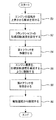
<エンジンの回転上昇のストラテジー制御>
制御器34は、図14に示されるように、ブロック50において、エンジンの回転を上昇させる要求を受ける。この要求は、パワートレイン制御モジュールによって送信され得ると共に、バッテリの充電状態及び運転者による動力要求のような要因に基づき得る。ブロック52において、クランクシャフトの目標回転速度が設定される。その目標回転速度は、車速、所望の変速ギア及びオフセット値等の要因に基づき得る。例えば、変速機の出力トルクが正の値であるならば、オフセット値も正の値である。その一方で、変速機の出力トルクが負の値であるならば、オフセット値も負の値である。ステップ54において、変速機の第1クラッチを作動させて、変速機がトルクを伝達する準備を行なう。ブロック56において、エンジン速度が、目標回転速度を達成するように制御される。ブロック58において、変速機の第2クラッチを作動させて、変速機がトルクを伝達する準備を更に行なう。ブロック60において、電動運転からの移行(離脱)が実行される。
<Strategy control of engine rotation rise>
図15に示されるように、ブロック62において、CISGがトルク制御にて調整される。ブロック64において、駆動輪トルクを一定に維持するように、(ERADのトルクからエンジンのトルクへの)動力源の移行が調整される。
As shown in FIG. 15, in
本発明の実施形態を示し、記述してきたが、これらの実施形態は、本発明の実行可能な形態の全てを示し、そして記述することを意図したものではない。また、明細書中で使用される単語は、限定というよりも寧ろ説明するためのものであり、本明細書の技術思想と範囲から逸脱することなく、種々の変更がなされ得ることを理解すべきである。 While embodiments of the invention have been shown and described, these embodiments show and do not intend to describe all possible forms of the invention. It should also be understood that the words used in the specification are intended to be illustrative rather than limiting and that various changes can be made without departing from the spirit and scope of the specification. It is.
10 HEVシステム
12 エンジン
14 CISG
16 変速機
18 クランクシャフト
20 ERAD
22、24 駆動輪
30 第1クラッチ
32 第2クラッチ
34 制御器
10
16
22, 24
Claims (7)
機械的動力を生成又は消費すべく、上記クランクシャフトを目標回転速度にて回転させるように構成された第1電気機械と、
ニュートラル状態から締結状態に選択的に移行することによって、上記クランクシャフトと上記駆動輪との間の機械的経路を選択的に形成し、該クランクシャフトと該駆動輪との間で該機械的経路を介して機械的動力を伝達するように構成された変速機と、
自動車を駆動するための電気的動力を生成するように構成された第2電気機械と、
機械的動力が上記駆動輪から上記クランクシャフトに伝達されるときには、上記変速機の同期速度に負のオフセット値を加えて上記目標回転速度を設定し、上記自動車を駆動するのに上記電気的動力を使用し、また、上記自動車を駆動するのに上記機械的動力を使用するように構成された少なくとも一つの制御器とを備える制御システム。 A control system for a hybrid electric vehicle comprising an engine having a drive wheel and a crankshaft,
A first electric machine configured to rotate the crankshaft at a target rotational speed to generate or consume mechanical power;
By selectively shifting from a neutral state to a fastening state, a mechanical path between the crankshaft and the driving wheel is selectively formed, and the mechanical path is between the crankshaft and the driving wheel. A transmission configured to transmit mechanical power via
A second electric machine configured to generate electrical power for driving the automobile;
When mechanical power is transmitted from the drive wheel to the crankshaft, the target rotational speed is set by adding a negative offset value to the synchronous speed of the transmission, and the electric power is used to drive the automobile. And at least one controller configured to use the mechanical power to drive the vehicle.
上記第1変化率は、上記第2変化率と略等しい、請求項1乃至5の何れかに記載の制御システム。 The at least one controller reduces the electrical power used to drive the vehicle at a first rate of change, and reduces the mechanical power used to drive the vehicle to a second rate of change. Is configured to increase at
The control system according to claim 1, wherein the first change rate is substantially equal to the second change rate.
Applications Claiming Priority (2)
| Application Number | Priority Date | Filing Date | Title |
|---|---|---|---|
| US11/938,412 US7837593B2 (en) | 2007-11-12 | 2007-11-12 | Method and system for using mechanical power to operate a hybrid electric vehicle |
| US11/938,412 | 2007-11-12 |
Publications (3)
| Publication Number | Publication Date |
|---|---|
| JP2009120189A JP2009120189A (en) | 2009-06-04 |
| JP2009120189A5 JP2009120189A5 (en) | 2013-01-17 |
| JP5373371B2 true JP5373371B2 (en) | 2013-12-18 |
Family
ID=40139602
Family Applications (1)
| Application Number | Title | Priority Date | Filing Date |
|---|---|---|---|
| JP2008289441A Expired - Fee Related JP5373371B2 (en) | 2007-11-12 | 2008-11-12 | Control device for hybrid electric vehicle |
Country Status (4)
| Country | Link |
|---|---|
| US (2) | US7837593B2 (en) |
| JP (1) | JP5373371B2 (en) |
| CN (1) | CN101434190B (en) |
| GB (1) | GB2454586B (en) |
Families Citing this family (16)
| Publication number | Priority date | Publication date | Assignee | Title |
|---|---|---|---|---|
| FR2875745B1 (en) * | 2004-09-24 | 2008-03-21 | Peugeot Citroen Automobiles Sa | CONTROL METHOD FOR A TRANSMISSION DEVICE BETWEEN A SHAFT OF A HEAT ENGINE AND A WHEEL SHAFT OF A VEHICLE |
| US8038573B2 (en) * | 2008-04-17 | 2011-10-18 | Bayerische Motoren Werke Aktiengesellschaft | Power development for rapid start in full-hybrid drives with optimized traction control |
| DE102009050957B4 (en) * | 2009-10-28 | 2018-07-26 | Dr. Ing. H.C. F. Porsche Aktiengesellschaft | mixed hybrid |
| US8647231B2 (en) * | 2010-07-07 | 2014-02-11 | Ford Global Technologies, Llc | Transitioning between electric-drive and parallel-drive in a hybrid-electric vehicle powertrain |
| CN110228460B (en) * | 2011-01-13 | 2023-09-26 | 卡明斯公司 | Systems, methods, and apparatus for controlling power output distribution in a hybrid powertrain |
| US8612078B2 (en) | 2011-08-08 | 2013-12-17 | Bae Systems Controls Inc. | Parallel hybrid electric vehicle power management system and adaptive power management method and program therefor |
| US8517892B2 (en) | 2011-08-08 | 2013-08-27 | Bae Systems Controls Inc. | Method and apparatus for controlling hybrid electric vehicles |
| GB2508669A (en) * | 2012-12-10 | 2014-06-11 | Jaguar Land Rover Ltd | A speed control system for a hybrid electric vehicle |
| KR101558812B1 (en) * | 2014-09-24 | 2015-10-07 | 현대자동차주식회사 | Motor torque control method in coasting state of hybrid electric vehicle |
| US10144414B2 (en) | 2014-12-18 | 2018-12-04 | Ford Global Technologies, Llc | Engine control for smooth clutch engagement in a hybrid vehicle |
| US11186162B2 (en) | 2016-03-15 | 2021-11-30 | Borgwarner, Inc. | Twin system electric all-wheel drive supplementary drive axle |
| KR20180067984A (en) * | 2016-12-13 | 2018-06-21 | 현대자동차주식회사 | Method and apparatus for controlling mhsg of mild hybrid electric vehicle |
| GB2570888B (en) * | 2018-02-07 | 2020-09-02 | Jaguar Land Rover Ltd | Transmission operation in a vehicle with an electric motor |
| GB2585503B (en) * | 2018-02-07 | 2021-09-01 | Jaguar Land Rover Ltd | Transmission operation in a vehicle with an electric motor |
| KR20200025105A (en) * | 2018-08-29 | 2020-03-10 | 현대자동차주식회사 | Control method and appratus for mild hybrid electric vehicle |
| US11046299B2 (en) * | 2019-05-16 | 2021-06-29 | Ford Global Technologies, Llc | Methods and system for operating a four wheel drive electric vehicle |
Family Cites Families (24)
| Publication number | Priority date | Publication date | Assignee | Title |
|---|---|---|---|---|
| CA2883981A1 (en) | 1998-09-14 | 2000-03-23 | Paice Llc | Hybrid vehicles |
| JP3948147B2 (en) * | 1999-02-03 | 2007-07-25 | マツダ株式会社 | Hybrid vehicle |
| JP3712684B2 (en) * | 2001-06-01 | 2005-11-02 | 本田技研工業株式会社 | Control device for hybrid vehicle |
| US6556910B2 (en) * | 2001-08-31 | 2003-04-29 | Aisin Aw Co., Ltd. | Control apparatus and method for vehicle having an idle stop function |
| JP3653028B2 (en) * | 2001-10-17 | 2005-05-25 | 本田技研工業株式会社 | Power transmission control device for vehicle |
| JP3915698B2 (en) * | 2002-12-27 | 2007-05-16 | アイシン・エィ・ダブリュ株式会社 | Control device for hybrid vehicle |
| JP3991882B2 (en) * | 2003-02-17 | 2007-10-17 | トヨタ自動車株式会社 | POWER OUTPUT DEVICE, ITS CONTROL METHOD, AND VEHICLE |
| CN100528655C (en) * | 2003-09-11 | 2009-08-19 | 日产柴油机车工业株式会社 | Gear shift control device of hybrid power vehicle |
| US7013213B2 (en) * | 2004-05-12 | 2006-03-14 | Ford Global Technologies, Llc | Method for controlling starting of an engine in a hybrid electric vehicle powertrain |
| US7465251B2 (en) * | 2004-07-10 | 2008-12-16 | Lingling Zhang | Hybrid electric vehicle |
| GB2416600B (en) | 2004-07-23 | 2008-06-04 | Ford Global Tech Llc | System and method for starting a vehicle |
| JP4134981B2 (en) * | 2004-12-16 | 2008-08-20 | 日産自動車株式会社 | Mode change control device for hybrid transmission |
| US7370715B2 (en) * | 2004-12-28 | 2008-05-13 | Ford Global Technologies, Llc | Vehicle and method for controlling engine start in a vehicle |
| US20060169504A1 (en) * | 2005-01-28 | 2006-08-03 | Eaton Corporation | Hybrid electric vehicle sequence for engine start |
| US7367415B2 (en) * | 2005-01-28 | 2008-05-06 | Eaton Corporation | Hybrid electric vehicle engine start technique |
| JP4457981B2 (en) * | 2005-05-26 | 2010-04-28 | トヨタ自動車株式会社 | Control device for vehicle drive device |
| JP4466514B2 (en) * | 2005-09-08 | 2010-05-26 | 日産自動車株式会社 | Engine start control device for hybrid vehicle |
| JP4285485B2 (en) * | 2006-01-24 | 2009-06-24 | トヨタ自動車株式会社 | POWER OUTPUT DEVICE, VEHICLE MOUNTING THE SAME, AND METHOD FOR CONTROLLING POWER OUTPUT DEVICE |
| CN100423963C (en) * | 2006-08-10 | 2008-10-08 | 上海交通大学 | Hybrid drive system in type of multiple series connection stepless speed change |
| US7713164B2 (en) * | 2007-06-26 | 2010-05-11 | Ford Global Technologies, Llc | Double step gear shifting in a hybrid electric vehicle |
| US7678013B2 (en) * | 2007-08-09 | 2010-03-16 | Ford Global Technologies, Llc | Launch control of a hybrid electric vehicle |
| US7743860B2 (en) * | 2007-10-09 | 2010-06-29 | Ford Global Technologies, Llc | Holding a hybrid electric vehicle on an inclined surface |
| US8020652B2 (en) * | 2007-12-04 | 2011-09-20 | Ford Global Technologies, Llc | Generator power-based cold start strategy |
| US8412426B2 (en) * | 2009-03-06 | 2013-04-02 | GM Global Technology Operations LLC | Multi-mode hybrid transmission and method for performing a quasi-asynchronous shift in a hybrid transmission |
-
2007
- 2007-11-12 US US11/938,412 patent/US7837593B2/en not_active Expired - Fee Related
-
2008
- 2008-10-15 CN CN2008101499045A patent/CN101434190B/en not_active Expired - Fee Related
- 2008-11-10 GB GB0820461.2A patent/GB2454586B/en not_active Expired - Fee Related
- 2008-11-12 JP JP2008289441A patent/JP5373371B2/en not_active Expired - Fee Related
-
2010
- 2010-10-15 US US12/905,143 patent/US7998024B2/en not_active Expired - Fee Related
Also Published As
| Publication number | Publication date |
|---|---|
| US7998024B2 (en) | 2011-08-16 |
| JP2009120189A (en) | 2009-06-04 |
| CN101434190B (en) | 2013-04-10 |
| GB2454586A (en) | 2009-05-13 |
| US7837593B2 (en) | 2010-11-23 |
| CN101434190A (en) | 2009-05-20 |
| US20090124450A1 (en) | 2009-05-14 |
| GB2454586A8 (en) | 2009-05-13 |
| GB0820461D0 (en) | 2008-12-17 |
| GB2454586B (en) | 2012-06-13 |
| US20110031049A1 (en) | 2011-02-10 |
Similar Documents
| Publication | Publication Date | Title |
|---|---|---|
| JP5373371B2 (en) | Control device for hybrid electric vehicle | |
| CA2988532C (en) | Mode transition control device for hybrid vehicle | |
| JP4265568B2 (en) | Mode transition control device for hybrid vehicle | |
| JP4739948B2 (en) | Vehicle engine start method and vehicle engine start control computer program | |
| US7972235B2 (en) | Hybrid powertrain system having selectively connectable engine, motor/generator, and transmission | |
| JP5371200B2 (en) | An engine start control device for a hybrid vehicle and an engine start control method for a hybrid vehicle. | |
| JP5382223B2 (en) | Control device for hybrid vehicle | |
| JP5867514B2 (en) | Vehicle control device | |
| JP4663395B2 (en) | Hybrid vehicle start control device | |
| JP2010536628A (en) | Method of starting an internal combustion engine started during load switching in a parallel type hybrid vehicle | |
| US8512202B2 (en) | Shift controller and shift controlling method | |
| JP2011020542A (en) | Electric vehicle control device | |
| US20130297107A1 (en) | Traction control system for a hybrid vehicle | |
| JP2018052320A (en) | Control device and control method for hybrid vehicle system | |
| JP5182072B2 (en) | Oil pump drive device for hybrid vehicle | |
| JP5029275B2 (en) | Driving force control device | |
| US20140038772A1 (en) | Traction Control System For A Hybrid Vehicle | |
| CN111216551B (en) | Control device for four-wheel drive vehicle | |
| KR101013879B1 (en) | Braking control method of hybrid electric vehicle | |
| WO2020148973A1 (en) | Vehicle control device | |
| JP4816265B2 (en) | VEHICLE POWER DEVICE AND CONTROL DEVICE THEREOF | |
| WO2022209383A1 (en) | Vehicle drive device | |
| WO2022181409A1 (en) | Drive device for vehicle | |
| JP2021098485A (en) | Control device of hybrid vehicle |
Legal Events
| Date | Code | Title | Description |
|---|---|---|---|
| A621 | Written request for application examination |
Free format text: JAPANESE INTERMEDIATE CODE: A621 Effective date: 20111024 |
|
| A521 | Request for written amendment filed |
Free format text: JAPANESE INTERMEDIATE CODE: A523 Effective date: 20121120 |
|
| A871 | Explanation of circumstances concerning accelerated examination |
Free format text: JAPANESE INTERMEDIATE CODE: A871 Effective date: 20121120 |
|
| RD02 | Notification of acceptance of power of attorney |
Free format text: JAPANESE INTERMEDIATE CODE: A7422 Effective date: 20121120 |
|
| A975 | Report on accelerated examination |
Free format text: JAPANESE INTERMEDIATE CODE: A971005 Effective date: 20121217 |
|
| A131 | Notification of reasons for refusal |
Free format text: JAPANESE INTERMEDIATE CODE: A131 Effective date: 20121225 |
|
| A977 | Report on retrieval |
Free format text: JAPANESE INTERMEDIATE CODE: A971007 Effective date: 20121228 |
|
| A521 | Request for written amendment filed |
Free format text: JAPANESE INTERMEDIATE CODE: A523 Effective date: 20130325 |
|
| A131 | Notification of reasons for refusal |
Free format text: JAPANESE INTERMEDIATE CODE: A131 Effective date: 20130507 |
|
| A521 | Request for written amendment filed |
Free format text: JAPANESE INTERMEDIATE CODE: A523 Effective date: 20130807 |
|
| TRDD | Decision of grant or rejection written | ||
| A01 | Written decision to grant a patent or to grant a registration (utility model) |
Free format text: JAPANESE INTERMEDIATE CODE: A01 Effective date: 20130827 |
|
| A61 | First payment of annual fees (during grant procedure) |
Free format text: JAPANESE INTERMEDIATE CODE: A61 Effective date: 20130919 |
|
| R150 | Certificate of patent or registration of utility model |
Ref document number: 5373371 Country of ref document: JP Free format text: JAPANESE INTERMEDIATE CODE: R150 Free format text: JAPANESE INTERMEDIATE CODE: R150 |
|
| R250 | Receipt of annual fees |
Free format text: JAPANESE INTERMEDIATE CODE: R250 |
|
| R250 | Receipt of annual fees |
Free format text: JAPANESE INTERMEDIATE CODE: R250 |
|
| R250 | Receipt of annual fees |
Free format text: JAPANESE INTERMEDIATE CODE: R250 |
|
| R250 | Receipt of annual fees |
Free format text: JAPANESE INTERMEDIATE CODE: R250 |
|
| LAPS | Cancellation because of no payment of annual fees |