JP5373068B2 - Lower cutter for shaving head of dry shaver - Google Patents
Lower cutter for shaving head of dry shaver Download PDFInfo
- Publication number
- JP5373068B2 JP5373068B2 JP2011511998A JP2011511998A JP5373068B2 JP 5373068 B2 JP5373068 B2 JP 5373068B2 JP 2011511998 A JP2011511998 A JP 2011511998A JP 2011511998 A JP2011511998 A JP 2011511998A JP 5373068 B2 JP5373068 B2 JP 5373068B2
- Authority
- JP
- Japan
- Prior art keywords
- lower cutter
- blade
- width
- strip
- shaving head
- Prior art date
- Legal status (The legal status is an assumption and is not a legal conclusion. Google has not performed a legal analysis and makes no representation as to the accuracy of the status listed.)
- Active
Links
- 230000002093 peripheral effect Effects 0.000 claims description 15
- 238000005520 cutting process Methods 0.000 claims description 13
- 230000001154 acute effect Effects 0.000 claims description 2
- 238000005452 bending Methods 0.000 description 8
- 230000007704 transition Effects 0.000 description 5
- 230000000694 effects Effects 0.000 description 4
- 239000000463 material Substances 0.000 description 4
- 238000009826 distribution Methods 0.000 description 2
- 238000005530 etching Methods 0.000 description 2
- 239000002184 metal Substances 0.000 description 2
- 230000009467 reduction Effects 0.000 description 2
- 238000000926 separation method Methods 0.000 description 2
- 230000003466 anti-cipated effect Effects 0.000 description 1
- 230000008878 coupling Effects 0.000 description 1
- 238000010168 coupling process Methods 0.000 description 1
- 238000005859 coupling reaction Methods 0.000 description 1
- 238000010586 diagram Methods 0.000 description 1
- 238000005265 energy consumption Methods 0.000 description 1
- 238000010438 heat treatment Methods 0.000 description 1
- 238000004519 manufacturing process Methods 0.000 description 1
- 230000007246 mechanism Effects 0.000 description 1
- 238000000034 method Methods 0.000 description 1
- 230000002028 premature Effects 0.000 description 1
- 230000008569 process Effects 0.000 description 1
- 230000001737 promoting effect Effects 0.000 description 1
Images


Classifications
-
- B—PERFORMING OPERATIONS; TRANSPORTING
- B26—HAND CUTTING TOOLS; CUTTING; SEVERING
- B26B—HAND-HELD CUTTING TOOLS NOT OTHERWISE PROVIDED FOR
- B26B19/00—Clippers or shavers operating with a plurality of cutting edges, e.g. hair clippers, dry shavers
- B26B19/02—Clippers or shavers operating with a plurality of cutting edges, e.g. hair clippers, dry shavers of the reciprocating-cutter type
- B26B19/04—Cutting heads therefor; Cutters therefor; Securing equipment thereof
- B26B19/044—Manufacture and assembly of cutter blocks
Landscapes
- Engineering & Computer Science (AREA)
- Manufacturing & Machinery (AREA)
- Life Sciences & Earth Sciences (AREA)
- Forests & Forestry (AREA)
- Mechanical Engineering (AREA)
- Dry Shavers And Clippers (AREA)
Description
本発明は、関連付けられた上部カッターとともに、請求項1の前半による乾式シェーバーの剃毛ヘッドを形成する、下部カッターに関する。 The invention relates to a lower cutter which, together with an associated upper cutter, forms the shaving head of a dry shaver according to the first half of claim 1.
このタイプの下部カッターは、米国特許第7,022,195 B2号で既知であり、この下部カッターは、一定幅又は中心に向って増大する幅を有する複数のストリップ形状の刃要素からなる。 A lower cutter of this type is known from US Pat. No. 7,022,195 B2, which consists of a plurality of strip-shaped blade elements having a constant width or a width increasing towards the center.
このようなカッターは、乾式シェーバーの剃毛ヘッドの内側に位置し、振動する方法で駆動され、有孔薄片に対して押し付けられ、剃毛プロセス中に複合荷重に曝される。 Such a cutter is located inside the shaving head of a dry shaver, is driven in a vibrating manner, is pressed against a perforated flake, and is subjected to complex loads during the shaving process.
例えば、これらは、ユーザがシェーバーを皮膚に対して押す接触圧力により作用されて、刃の幅に対応する軸の周囲の曲げ荷重にストリップ形状の刃を曝す。毛髪の剪毛中、切断力による更なる機械的付加が発生するが、これは、頂点での曲げ荷重であり、外向き方向の2軸曲げ及びねじれからなる複合荷重となる。有孔薄片と下部カッター自体との間の摩擦により、更なる荷重が作り出される。 For example, they are acted upon by the contact pressure with which the user pushes the shaver against the skin, exposing the strip-shaped blade to bending loads around an axis corresponding to the width of the blade. While the hair is being trimmed, further mechanical loading due to the cutting force occurs, which is a bending load at the apex, resulting in a combined load consisting of biaxial bending and twisting in the outward direction. Additional load is created by friction between the perforated flake and the lower cutter itself.
既知のタイプによる下部カッターの設計は、有孔薄片とそれに関連付けられる下部カッターの摩擦表面との間の粘性摩擦による非常に高い摩擦損失を生成する、という欠点がある。これにより、高エネルギー消費がもたらされ、ユーザにとって不快な剃毛部品の加熱並びに早期磨耗がもたらされる。個々の刃の長さにわたる不均一な機械的応力分布のために、剃毛ヘッドがユーザの皮膚に対して押し付けられたときに起こる力に起因して、これらの刃は、刃の全長にわたって不均一に隆起する。これが、下部カッターと有孔薄片との間の直接的接触の部分的損失を招き、その結果、有孔薄片に既に通された毛髪が切断されずに単に引き込まれて、毛髪が皮膚から痛いほど引っ張られる。その上、不均一な刃の隆起は、有孔薄片を損傷させ得る。 The known type of lower cutter design has the disadvantage of producing very high friction losses due to viscous friction between the perforated flake and the associated friction surface of the lower cutter. This results in high energy consumption and leads to heating and premature wear of the shaving parts that are uncomfortable for the user. Due to the non-uniform mechanical stress distribution over the length of the individual blades, these blades are non-uniform over the entire length of the blade due to the forces that occur when the shaving head is pressed against the user's skin. Raises uniformly. This leads to a partial loss of direct contact between the lower cutter and the perforated flake, so that the hair already passed through the perforated flake is simply drawn without being cut and the hair becomes so painful from the skin. Be pulled. Moreover, uneven blade ridges can damage perforated flakes.
したがって、本発明の目的は、上記のタイプの下部カッターをその性能及び安定性に関してコスト効率のよい方法で改善することである。この目的は、請求項1に特徴付けられた機構により、本発明によって達成される。 Accordingly, it is an object of the present invention to improve a lower cutter of the type described above in a cost effective manner with respect to its performance and stability. This object is achieved according to the invention by the mechanism characterized in claim 1.
本発明による解決策は、材料荷重が個々の刃の全長にわたって均一に分布されることにより、重荷重においてでさえも有孔薄片と下部カッターとの間の恒久的な均一の接触が保証されることをもたらす。これは、実際の切断領域において安定性の損失なしに刃を狭く維持することも可能にして、有孔薄片と下部カッターとの間の粘性摩擦を低減するのを可能にする。これはまた、使用される材料のより優れた活用を可能にする。 The solution according to the invention ensures a uniform and uniform contact between the perforated flake and the lower cutter, even at heavy loads, because the material load is evenly distributed over the entire length of the individual blades. Bring things. This also makes it possible to keep the blade narrow without any loss of stability in the actual cutting area, which makes it possible to reduce the viscous friction between the perforated flake and the lower cutter. This also allows for better utilization of the materials used.
好ましい実施形態によると、本発明では、ストリップ刃の幅のテーパー部がステップレスであり、それによって刃に沿った均等の荷重分布が推進される。具体的には、ストリップのテーパー部は、弓状に設計される。 According to a preferred embodiment, in the present invention, the taper width of the strip blade is stepless, thereby promoting an even load distribution along the blade. Specifically, the taper portion of the strip is designed in an arc shape.
刃のストリップ幅のテーパー部が、少なくとも2つの遷移半径を有して組み入れられる場合、周辺領域と刃自体との間の遷移領域で刃が破損する恐れは減少する。遷移半径を適切に設計することにより、この遷移領域のノッチ効果を事実上取り除くことができる。 If the taper width of the blade strip width is incorporated with at least two transition radii, the risk of the blade breaking at the transition region between the peripheral region and the blade itself is reduced. By appropriately designing the transition radius, this notch effect in the transition region can be virtually eliminated.
刃は、好ましくは、ストリップの中心線に対して対称形を持つように設計され、かつ剃毛中に起こる切断力を減少させるために鋭角の刃先を有するのが好ましい。 The blade is preferably designed to be symmetrical with respect to the center line of the strip and preferably has an acute edge to reduce the cutting force that occurs during shaving.
本発明の更なる目的、特徴、利点、及び予想される用途が、以下の代表的な実施形態の説明から明白になるであろう。本発明の要旨は、説明される又は描写される特徴の全てを、個々に又は組み合わせて、請求項のそれらの要約又はそれらの付属物に関係なく、具体化するものである。 Further objects, features, advantages and anticipated applications of the present invention will become apparent from the following description of exemplary embodiments. The gist of the invention embodies all of the features described or depicted, individually or in combination, regardless of their summary in the claims or their appendices.
以下について図示する。
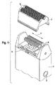
図1に示される乾式シェーバーは、特に、電気モータ(図示せず)及び任意にエネルギーを蓄える充電式電池(やはり図示せず)を収容する役目をするケーシング1を含み、またオン/オフスイッチ2を備える。乾式シェーバーの上面で、振動のために駆動される駆動要素3がケーシング1から出ている。下部カッター4は、既知の適切な/好適な連結手段を介して駆動要素3と係合する。これにより、互いに対して平行に配置された2つの下部カッター4が、両矢印5のようにそれらの長手方向延長部に沿って振動する方法で駆動されるのが可能になる。 The dry shaver shown in FIG. 1 includes in particular a casing 1 which serves to house an electric motor (not shown) and optionally a rechargeable battery (also not shown) for storing energy, and an on / off switch 2. Is provided. On the upper surface of the dry shaver, a driving element 3 driven for vibration exits the casing 1. The lower cutter 4 engages the drive element 3 via known suitable / suitable coupling means. This allows two lower cutters 4 arranged parallel to each other to be driven in a manner that vibrates along their longitudinal extensions as indicated by double arrows 5.
下部カッター4は、それぞれが有孔薄片6として設計された2つの上部カッターによって少なくとも部分的に囲まれている。それらは、取り換え可能なフレーム7に取り付けられており、このフレームはケーシング1と噛合することができる。有孔薄片6は、貫通する開口部でその全表面にわたって穿孔され、これは、穴及び/又はスリットとして設計することができ、これを通して、剃毛される毛髪が剃毛ヘッドに入る。薄片の貫通する開口部及び下部カッター4の両方の上に設計された刃先により、かつ有孔薄片6に対する下部カッター4の動きにより、剃毛ヘッドに入った毛髪は、関連付けられた剪毛エッジの間で剪毛される。
The lower cutter 4 is at least partly surrounded by two upper cutters, each designed as a perforated flake 6. They are attached to a
図2に示される本発明による下部カッター4は、2つの周辺領域10及び9の間のストリップの形態で延びる、互いに平行に延びる多数のU型刃8を有する。2つの周辺領域9及び10のそれぞれは、支持部材に接続するための取付け区域11をその前端部及び後端部に有し、その詳細は図には示されていないが、これは最終的に下部カッター4を乾式シェーバーの駆動要素3に接続する役目をする。2つの取付け区域11の間のそれぞれの周辺領域9及び10の長手方向延長部は、両矢印5による振動の方向に対応する。刃8は、本明細書に示される代表的な実施形態によると、周辺領域9、10の長手方向延長部に垂直に延びる。下部カッター4の刃8の幅及び刃の分離幅Tは、周辺領域の長手方向延長部に平行に測定される。
The lower cutter 4 according to the invention shown in FIG. 2 has a number of
既に図2で見られ、図3により詳しく示されるように、ストリップ型刃8の幅は、その長さL1に沿って一定ではなく、むしろ周辺区域9から弧の頂点に向ってテーパーするテーパー部を持ち、そこから周辺領域10に向って再び広がっている。これは、図3による図で特に明白である。
As already seen in FIG. 2 and shown in more detail in FIG. 3, the width of the strip-
図3は、中心線M及び頂点Zの両方に対して対称形を持つように設計された、個々の刃8の展開図を示す。周辺領域9、10が、約1mmの分離幅Tをもって図3に示される。
FIG. 3 shows an exploded view of the
刃8の全長L1は約11.5mmである。テーパーするテーパー部を持つ刃8の全領域は、両側が末端領域9、10において内径R1の延出部品に隣接しており、約8.9mmの長さL2に及ぶ。
The total length L1 of the
刃8は、周辺領域9、10から始まって、約0.58mmの幅B1まで、約0.2mmの窪んだ内径R1によってテーパーするテーパー部を持つ。それに隣接するのは、約33mmの凸状の外形をもつ外径R2である。この方法で、刃は、この領域においてその長手方向延長部に沿って凸状の外形を得る。半径R2の内端部において、刃は、約3.5mmの窪んだ内径R3によって平行の中央区域に遷移する。この区域は、0.32mmの幅B2及び約3.1mmの長さL3を有する。
The
半径R1による刃の幅のテーパー部によりノッチ効果が取り除かれるが、このノッチ効果は、周辺領域9、10と刃8自体との間の連結領域において刃の破損をもたらし得、また切断力に起因して起こる曲げ荷重により起こるものである。外径R2は、最大の曲げ及びねじれ荷重の領域で応力を均等に分配して、応力ピークを防ぐ。内径R3は、R2と平行の中央区域L3との間のノッチ効果を取り除く。
Although the notch effect is removed by the taper of the blade width due to the radius R1, this notch effect can lead to blade breakage in the connection region between the
周辺領域9、10から頂点の軸Zにかけての刃8の断面縮小は、切断力及び摩擦力によりもたらされる曲げ及びねじれの動きの減少にほぼしたがって起こり、刃の長さに沿って(又はU型に曲げられた最終的な状態では、刃の高さに沿って)全体的に極めて一様に分布された応力荷重を生み出す。これは、最適な材料活用を助け、一様でない変形を防ぐ。
The reduction in the cross section of the
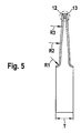
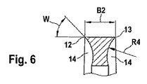
図4は、もとは平らな下部カッター4を適当なU型に曲げることによって作られた、曲げられた刃要素8の図を示す。同様に、もとの平らな下部カッター4は、具体的には、個々の刃8の間のスリットがエッチングされるストリップ型の金属の出発形状からエッチング法によって作られる。次いでこの出発形状は、U型を形成するように曲げられて、図2に示されるような下部カッターが得られる。図5及び6にはっきりと示されるように、エッチングによる製造の結果、それぞれの刃8の2つの対向する刃先12、13の領域にアンダーカットが作り出される。U型に曲げた後、このアンダーカット14は、弧の内側にある。図4で見ることができるように、出発金属シートの材料厚さDは、約0.3mmである。
FIG. 4 shows a view of a
図6にはっきりと示される、2つの刃先12、13のそれぞれの下にあるアンダーカットは、約0.3mmの半径R4に沿って延び、刃先12、13において約50°の刃先角度Wを作り出す。
The undercut under each of the two
Claims (4)
前記ストリップの幅の前記テーパー部が、ステップレスであり、
前記刃は2つの周辺領域(9、10)から中心に向って内側へ窪んだ内径(R1、R3)をもつ2つの凹部によりテーパーし、
内側へ窪んだ内径(R1、R3)をもつ2つの凹部間に、外径R2をもつ凸部が形成されていることを特徴とする下部カッター。 A lower cutter (4) that, together with an associated upper cutter (6), forms a shaving head of a dry shaver, wherein the upper cutter at least partially surrounds the lower cutter (4). ) And the lower cutter (4) has a plurality of spaced apart blades with cutting edges (12, 13) in the form of strips between two peripheral areas (9, 10) And the cross-section is essentially U-shaped, and the width of the strip has a tapered portion whose width tapers in the direction from the two peripheral regions (9, 10) to the center (Z),
The tapered portion of the width of the strip is stepless;
The blade is tapered by two recesses with a diameter (R1, R3) among recessed inwardly toward the center from the two peripheral regions (9, 10),
Between two recesses inner having a diameter (R1, R3) recessed inward, the lower cutter, wherein a convex portion having an outer diameter R2 is formed.
Applications Claiming Priority (3)
| Application Number | Priority Date | Filing Date | Title |
|---|---|---|---|
| DE102008027224A DE102008027224A1 (en) | 2008-06-06 | 2008-06-06 | Undercutter for the shaving head of a dry shaver |
| DE102008027224.8 | 2008-06-06 | ||
| PCT/EP2009/003600 WO2009146798A1 (en) | 2008-06-06 | 2009-05-20 | Lower cutter for the shaving head of a dry shaver |
Publications (3)
| Publication Number | Publication Date |
|---|---|
| JP2011521750A JP2011521750A (en) | 2011-07-28 |
| JP2011521750A5 JP2011521750A5 (en) | 2013-09-12 |
| JP5373068B2 true JP5373068B2 (en) | 2013-12-18 |
Family
ID=40957941
Family Applications (1)
| Application Number | Title | Priority Date | Filing Date |
|---|---|---|---|
| JP2011511998A Active JP5373068B2 (en) | 2008-06-06 | 2009-05-20 | Lower cutter for shaving head of dry shaver |
Country Status (6)
| Country | Link |
|---|---|
| US (1) | US8732961B2 (en) |
| EP (1) | EP2303524B1 (en) |
| JP (1) | JP5373068B2 (en) |
| CN (1) | CN102056716B (en) |
| DE (1) | DE102008027224A1 (en) |
| WO (1) | WO2009146798A1 (en) |
Families Citing this family (6)
| Publication number | Priority date | Publication date | Assignee | Title |
|---|---|---|---|---|
| DE102005036383A1 (en) * | 2005-07-29 | 2007-02-01 | Braun Gmbh | Shaving head for an electric shaver comprises a blade with an outer delimiting section facing an upper blade which is raised opposite the cutting edge |
| DE102008027224A1 (en) | 2008-06-06 | 2009-12-10 | Braun Gmbh | Undercutter for the shaving head of a dry shaver |
| JP6118475B1 (en) | 2014-04-18 | 2017-04-19 | コーニンクレッカ フィリップス エヌ ヴェKoninklijke Philips N.V. | Blade set, hair cutting device, and related manufacturing method |
| TR201911089T4 (en) | 2014-07-04 | 2019-08-21 | Koninklijke Philips Nv | Fixed blade and related manufacturing method for it. |
| IT201900011250A1 (en) * | 2019-07-09 | 2021-01-09 | Gamma Piu S R L | ELECTRIC HAIR CUTTER |
| CN111390978B (en) * | 2020-04-24 | 2024-06-18 | 中山市小石陶瓷刀片有限公司 | Reciprocating razor head and manufacturing method thereof |
Family Cites Families (17)
| Publication number | Priority date | Publication date | Assignee | Title |
|---|---|---|---|---|
| US2144525A (en) * | 1936-12-19 | 1939-01-17 | American Safety Razor Corp | Process of making dry shaver parts |
| US2223156A (en) * | 1937-12-07 | 1940-11-26 | Remington Rand Inc | Electric dry shaver |
| US2307471A (en) * | 1938-09-21 | 1943-01-05 | Remington Rand Inc | Shaving implement |
| US2325606A (en) * | 1940-07-26 | 1943-08-03 | Gillette Safety Rasor Company | Shaving implement |
| US2325605A (en) * | 1941-06-14 | 1943-08-03 | Nordberg Manufacturing Co | Impact member for impact crushers and securing means therefor |
| JP3237868B2 (en) * | 1991-07-15 | 2001-12-10 | 松下電工株式会社 | Manufacturing method of inner blade of reciprocating electric razor |
| DE4423503C1 (en) * | 1994-07-05 | 1995-04-20 | Braun Ag | Bottom blade for a dry shaver apparatus |
| KR100447912B1 (en) * | 1996-04-26 | 2004-11-03 | 산요덴키가부시키가이샤 | Electric shaver and method of manufacturing outer blade |
| GB9614160D0 (en) * | 1996-07-05 | 1996-09-04 | Gillette Co | Dry shaving apparatus |
| KR100511851B1 (en) | 2001-09-10 | 2005-09-05 | 마츠시다 덴코 가부시키가이샤 | Method of manufacturing inner blade for electric razor |
| JP2005198795A (en) | 2004-01-15 | 2005-07-28 | Izumi Products Co | Method of manufacturing cutter of reciprocating type electric razor and cutter |
| JP2006042899A (en) * | 2004-07-30 | 2006-02-16 | Matsushita Electric Works Ltd | Inner blade of reciprocating type electric razor |
| KR200391316Y1 (en) | 2005-01-28 | 2005-08-02 | 오태준 | Cutting blade assembly of electric shave |
| DE102005036383A1 (en) * | 2005-07-29 | 2007-02-01 | Braun Gmbh | Shaving head for an electric shaver comprises a blade with an outer delimiting section facing an upper blade which is raised opposite the cutting edge |
| JP4963020B2 (en) * | 2005-08-23 | 2012-06-27 | 株式会社泉精器製作所 | Reciprocating electric razor inner blade |
| DE102006023774A1 (en) * | 2006-05-20 | 2007-11-22 | Braun Gmbh | Undercutter for a dry razor shaving head |
| DE102008027224A1 (en) | 2008-06-06 | 2009-12-10 | Braun Gmbh | Undercutter for the shaving head of a dry shaver |
-
2008
- 2008-06-06 DE DE102008027224A patent/DE102008027224A1/en not_active Ceased
-
2009
- 2009-05-20 WO PCT/EP2009/003600 patent/WO2009146798A1/en active Application Filing
- 2009-05-20 EP EP09757181.4A patent/EP2303524B1/en active Active
- 2009-05-20 JP JP2011511998A patent/JP5373068B2/en active Active
- 2009-05-20 CN CN200980121069.7A patent/CN102056716B/en active Active
-
2010
- 2010-12-03 US US12/959,683 patent/US8732961B2/en active Active
Also Published As
| Publication number | Publication date |
|---|---|
| EP2303524A1 (en) | 2011-04-06 |
| CN102056716B (en) | 2016-10-19 |
| US20110067244A1 (en) | 2011-03-24 |
| US8732961B2 (en) | 2014-05-27 |
| DE102008027224A1 (en) | 2009-12-10 |
| EP2303524B1 (en) | 2013-09-11 |
| WO2009146798A1 (en) | 2009-12-10 |
| JP2011521750A (en) | 2011-07-28 |
| CN102056716A (en) | 2011-05-11 |
Similar Documents
| Publication | Publication Date | Title |
|---|---|---|
| JP5373068B2 (en) | Lower cutter for shaving head of dry shaver | |
| JP6239134B2 (en) | Razor blade and razor cartridge to which this is applied | |
| KR101695988B1 (en) | Rotator blade and small electric instrument having rotator blade | |
| JP3189610U (en) | Electric razor cutting head | |
| CN100478144C (en) | An electrical hair removal appliance and trimming system thereof | |
| US20100077617A1 (en) | Razors and razor cartridges with a decreased total interblade span | |
| BR112015029525B1 (en) | stationary cutting blade for a hair trimming device; cutting set; hair trimming device; process for making a stationary cutting blade for a hair trimming device | |
| JP5406769B2 (en) | Electric razor | |
| CN101107104A (en) | Electric hair-removing device | |
| JP2014158939A (en) | Hair-clipping device | |
| US20110232098A1 (en) | Electric shaver | |
| JP2011521750A5 (en) | ||
| JP5026419B2 (en) | Shaving head for electric shaving equipment | |
| JP5021495B2 (en) | Hair trimming device and cutter member assembly for such device | |
| JP4963020B2 (en) | Reciprocating electric razor inner blade | |
| US20050198827A1 (en) | Cutting system construction for electric dry foil shavers | |
| JP2004521689A (en) | Razor mechanism for electric razor | |
| US7900360B2 (en) | Cutter assembly and method of producing same | |
| RU2434738C2 (en) | Lower knife for electric razor head | |
| US3060571A (en) | Blade for electric shaver | |
| JP6244611B1 (en) | Cutting tools with serrated blades, shavings, saws, files, graters, metal tools such as electric chainsaws and their manufacturing methods, and for non-metallic materials, blades such as brushes and electric brushes and their unit Production method. | |
| US20100236073A1 (en) | Electric Razors | |
| CN117507013A (en) | Cutting blade, reciprocating razor head and razor | |
| JP2014023742A (en) | Electric razor | |
| JP2004236790A (en) | Hair cutter |
Legal Events
| Date | Code | Title | Description |
|---|---|---|---|
| A621 | Written request for application examination |
Free format text: JAPANESE INTERMEDIATE CODE: A621 Effective date: 20101201 |
|
| A977 | Report on retrieval |
Free format text: JAPANESE INTERMEDIATE CODE: A971007 Effective date: 20120920 |
|
| A131 | Notification of reasons for refusal |
Free format text: JAPANESE INTERMEDIATE CODE: A131 Effective date: 20120921 |
|
| A521 | Request for written amendment filed |
Free format text: JAPANESE INTERMEDIATE CODE: A523 Effective date: 20121210 |
|
| A131 | Notification of reasons for refusal |
Free format text: JAPANESE INTERMEDIATE CODE: A131 Effective date: 20130507 |
|
| A524 | Written submission of copy of amendment under article 19 pct |
Free format text: JAPANESE INTERMEDIATE CODE: A524 Effective date: 20130723 |
|
| TRDD | Decision of grant or rejection written | ||
| A01 | Written decision to grant a patent or to grant a registration (utility model) |
Free format text: JAPANESE INTERMEDIATE CODE: A01 Effective date: 20130820 |
|
| A61 | First payment of annual fees (during grant procedure) |
Free format text: JAPANESE INTERMEDIATE CODE: A61 Effective date: 20130918 |
|
| R150 | Certificate of patent or registration of utility model |
Ref document number: 5373068 Country of ref document: JP Free format text: JAPANESE INTERMEDIATE CODE: R150 Free format text: JAPANESE INTERMEDIATE CODE: R150 |
|
| R250 | Receipt of annual fees |
Free format text: JAPANESE INTERMEDIATE CODE: R250 |
|
| R250 | Receipt of annual fees |
Free format text: JAPANESE INTERMEDIATE CODE: R250 |
|
| R250 | Receipt of annual fees |
Free format text: JAPANESE INTERMEDIATE CODE: R250 |
|
| R250 | Receipt of annual fees |
Free format text: JAPANESE INTERMEDIATE CODE: R250 |
|
| R250 | Receipt of annual fees |
Free format text: JAPANESE INTERMEDIATE CODE: R250 |
|
| R250 | Receipt of annual fees |
Free format text: JAPANESE INTERMEDIATE CODE: R250 |
|
| R250 | Receipt of annual fees |
Free format text: JAPANESE INTERMEDIATE CODE: R250 |
|
| R250 | Receipt of annual fees |
Free format text: JAPANESE INTERMEDIATE CODE: R250 |
|
| R250 | Receipt of annual fees |
Free format text: JAPANESE INTERMEDIATE CODE: R250 |