JP5372197B2 - Game machine - Google Patents
Game machine Download PDFInfo
- Publication number
- JP5372197B2 JP5372197B2 JP2012073470A JP2012073470A JP5372197B2 JP 5372197 B2 JP5372197 B2 JP 5372197B2 JP 2012073470 A JP2012073470 A JP 2012073470A JP 2012073470 A JP2012073470 A JP 2012073470A JP 5372197 B2 JP5372197 B2 JP 5372197B2
- Authority
- JP
- Japan
- Prior art keywords
- state
- game
- symbol
- value
- special symbol
- Prior art date
- Legal status (The legal status is an assumption and is not a legal conclusion. Google has not performed a legal analysis and makes no representation as to the accuracy of the status listed.)
- Expired - Fee Related
Links
Images


Abstract
Description
本発明は、遊技球を用いて所定の遊技を行うことが可能であり、所定の移行条件の成立にもとづいて遊技者にとって有利な特定遊技状態に移行させるパチンコ遊技機やスロット機等の遊技機に関する。 The present invention is capable of performing a predetermined game using a game ball, and a gaming machine such as a pachinko gaming machine or a slot machine that shifts to a specific gaming state advantageous to a player based on establishment of a predetermined transition condition About.
遊技機として、遊技媒体である遊技球を発射装置によって遊技領域に発射し、遊技領域に設けられている入賞口などの入賞領域に遊技球が入賞すると、所定個の賞球が遊技者に払い出されるものがある。さらに、識別情報を可変表示(「変動」ともいう。)可能な複数の可変表示部が設けられ、複数の可変表示部のいずれかにおいて識別情報の可変表示の表示結果が特定表示結果となった場合に、遊技状態(遊技機の状態。より具体的には、遊技機が制御されている状態。)を、所定の遊技価値を遊技者に与えるように構成されたものがある。 As a gaming machine, a game ball, which is a game medium, is launched into a game area by a launching device, and when a game ball wins a prize area such as a prize opening provided in the game area, a predetermined number of prize balls are paid out to the player. There is something to be done. Furthermore, a plurality of variable display units capable of variably displaying the identification information (also referred to as “variation”) are provided, and the display result of the variable display of the identification information is the specific display result in any of the plurality of variable display units. In some cases, a gaming state (a state of a gaming machine, more specifically, a state in which the gaming machine is controlled) is configured to give a predetermined gaming value to a player.
なお、遊技価値とは、遊技機の遊技領域に設けられた可変入賞球装置の状態が打球が入賞しやすい遊技者にとって有利な状態になることや、遊技者にとって有利な状態になるための権利を発生させたりすることや、賞球払出の条件が成立しやすくなる状態になることである。 The game value is the right that the state of the variable winning ball apparatus provided in the gaming area of the gaming machine becomes advantageous for a player who is easy to win, and the right for becoming advantageous for a player. In other words, or a condition for winning a prize ball is easily established.
パチンコ遊技機では、始動入賞口に遊技球が入賞したことにもとづいて可変表示部において開始される特別図柄(識別情報)の可変表示の表示結果として、あらかじめ定められた特定の表示態様が導出表示された場合に、「大当り」が発生する。なお、導出表示とは、図柄を停止表示させることである(いわゆる再変動の前の停止を除く。)。大当りが発生すると、例えば、大入賞口が所定回数開放して打球が入賞しやすい大当り遊技状態に移行する。そして、各開放期間において、所定個(例えば10個)の大入賞口への入賞があると大入賞口は閉成する。なお、各開放について開放時間(例えば29秒)が決められ、入賞数が所定個に達しなくても開放時間が経過すると大入賞口は閉成する。以下、各々の大入賞口の開放期間をラウンドということがある。 In a pachinko machine, a specific display mode determined in advance is derived and displayed as a display result of variable display of a special symbol (identification information) that is started in the variable display unit based on the winning of a game ball at the start winning opening. If this happens, a “big hit” will occur. Note that the derivation display is to stop and display a symbol (excluding stop before so-called re-variation). When the big hit occurs, for example, the big winning opening is opened a predetermined number of times, and the game shifts to a big hit gaming state where the hit ball is easy to win. And in each open period, if there is a prize for a predetermined number (for example, 10) of the big prize opening, the big prize opening is closed. An opening time (for example, 29 seconds) is determined for each opening, and even if the number of winnings does not reach a predetermined number, the big winning opening is closed when the opening time elapses. Hereinafter, the opening period of each special winning opening may be referred to as a round.
また、可変表示装置において、最終停止図柄(例えば左右中図柄のうち中図柄)となる図柄以外の図柄が、所定時間継続して、特定の表示結果と一致している状態で停止、揺動、拡大縮小もしくは変形している状態、または、複数の図柄が同一図柄で同期して変動したり、表示図柄の位置が入れ替わっていたりして、最終結果が表示される前で大当り発生の可能性が継続している状態(以下、これらの状態をリーチ状態という。)において行われる演出をリーチ演出という。また、リーチ状態やその様子をリーチ態様という。さらに、リーチ演出を含む可変表示をリーチ可変表示という。そして、可変表示装置に変動表示される図柄の表示結果が特定の表示結果でない場合には「はずれ」となり、変動表示状態は終了する。遊技者は、大当りをいかにして発生させるかを楽しみつつ遊技を行う。 Further, in the variable display device, the symbols other than the symbol that becomes the final stop symbol (for example, the middle symbol of the left and right middle symbols) are continuously stopped for a predetermined time, and are stopped, swung, There is a possibility that a big hit will occur before the final result is displayed due to the state of scaling or deformation, or multiple symbols changing synchronously with the same symbol, or the position of the display symbol being switched An effect performed in a continuing state (hereinafter, these states are referred to as reach states) is referred to as reach effect. Further, the reach state and its state are referred to as a reach mode. Furthermore, variable display including reach production is called reach variable display. Then, when the display result of the symbol variably displayed on the variable display device is not a specific display result, it becomes “out of” and the variability display state ends. A player plays a game while enjoying how to generate a big hit.
ところで、遊技機(例えば大入賞口)の故障や不正行為によって、大入賞口が開放するタイミングでないときに遊技球が大入賞口に入賞して賞球の払い出しが行われることがある。この場合、過剰な賞球の払い出しが行われ、遊技店に不利益を及ぼしてしまう。このような事態を防止するために、特許文献1には、大入賞口の閉鎖から所定時間経過後に所定数の遊技球が大入賞口に入賞すると、異常入賞が生じたと判定して異常報知を実行するように構成された遊技機が提案されている。
By the way, due to a malfunction of a gaming machine (for example, a big prize opening) or an illegal act, there is a case where a game ball wins the big prize opening and the payout of the prize ball is performed when it is not time to open the big prize opening. In this case, excessive prize balls are paid out, which is disadvantageous to the game store. In order to prevent such a situation, in
上記のような特許文献1に記載された遊技機では、大当り遊技状態に移行されているときも、大当り遊技状態に移行されていないときも、同一処理である大入賞口の異常判定処理を実行する。ここで、大当り遊技状態に移行されているときには、大入賞口の各開放(各ラウンド)で所定個(例えば10個)以上の遊技球が入賞してしまうことがあるのに対し、大当り遊技状態に移行されていないときには、大入賞口への入賞が本来生じるはずがない。このため、大当り遊技状態に移行されていないときよりも大当り遊技状態に移行されているときの方が異常入賞の判定における入賞数を多めに設定する必要がある。しかし、特許文献1に記載された遊技機では、同一処理で大入賞口の異常判定を行うように構成されているので、異常入賞を検出できない事態が生じるおそれがある。
In the gaming machine described in
そこで、本発明は、異常入賞を的確に検出し判定することができる遊技機を提供することを目的とする。 Therefore, an object of the present invention is to provide a gaming machine capable of accurately detecting and determining an abnormal winning.
(手段1)本発明による遊技機は、遊技球を用いて所定の遊技を行うことが可能であり、所定の移行条件の成立にもとづいて遊技者にとって有利な特定遊技状態(例えば、大当り遊技状態または小当り遊技状態;具体的には特別図柄通常処理におけるステップS305〜S311の処理が実行されている状態)に移行させる遊技機であって、可変表示の第1実行条件が成立(例えば、第1始動入賞口13への入賞)した後、可変表示の開始が可能となる第1開始条件が成立したことにもとづいて各々を識別可能な第1識別情報(例えば第1特別図柄)の可変表示を開始し表示結果を導出表示する第1可変表示手段(例えば、第1特別図柄表示器8a)と、可変表示の第2実行条件が成立(例えば、第2始動入賞口14への入賞)した後、可変表示の開始が可能となる第2開始条件が成立したことにもとづいて各々を識別可能な第2識別情報(例えば第1特別図柄)の可変表示を開始し表示結果を導出表示する第2可変表示手段(例えば、第2特別図柄表示器8b)と、特定遊技状態において遊技球が入賞しない閉鎖状態と遊技球が入賞可能な開放状態とに変化可能な可変入賞球装置(例えば、大入賞口を構成する特別可変入賞球装置20)と、可変入賞球装置に入賞した遊技球を検出して検出信号を出力する検出手段(例えば、カウントスイッチ23)と、遊技球が進入しにくいまたは進入しない閉状態と遊技球が進入可能な開状態とに変化可能な可変始動入賞装置とを備え、第2実行条件は、可変始動入賞装置に遊技球が進入したことにもとづいて成立し、遊技の進行を制御する遊技制御手段を備え、遊技制御手段は、遊技状態を示すデータにもとづいて第1可変表示手段および第2可変表示手段と可変入賞球装置との状態を制御する状態制御手段を含み、状態制御手段は、特定遊技状態として、可変入賞球装置を第1期間開放状態に制御する第1特定遊技状態、または可変入賞球装置を第1期間とは異なる第2期間開放状態に制御する第2特定遊技状態に移行させることが可能であり、第1実行条件が成立した場合と第2実行条件が成立した場合とで、異なる割合で、第1特定遊技状態と第2特定遊技状態とを選択する特定遊技状態選択手段を含み、遊技状態を示すデータが所定値であるときに可変入賞球装置を開放状態に制御し、遊技制御手段は、第1開始条件が成立した第1可変表示手段における第1識別情報の表示結果を決定するための第1表示結果決定処理と、第2開始条件が成立した第2可変表示手段における第2識別情報の表示結果を決定するための第2表示結果決定処理とを、同一の処理ルーチンにより実行し、第1可変表示手段と第2可変表示手段とのうち、可変表示の開始条件が成立した可変表示手段における識別情報の表示結果を当該表示結果の導出表示前に決定する表示結果決定処理手段と、第1可変表示手段と第2可変表示手段とのそれぞれで実行される可変表示について、第1可変表示手段と第2可変表示手段とのうち、開始条件が成立した可変表示手段における可変表示開始時から可変表示終了時までの可変表示時間を含む可変表示パターンを複数の可変表示パターンから選択する可変表示パターン選択手段と、特定遊技状態以外の遊技状態において検出手段によって遊技球の入賞が検出されたことにもとづいて、異常入賞が発生したか否かを判定する異常入賞判定手段とを含み、異常入賞判定手段は、遊技状態を示すデータが所定値以上の数値であるときに異常入賞が発生したか否かを判定するための処理を実行しないことを特徴とする。
このような構成によれば、異常入賞を的確に検出し判定することができる。
(Means 1) The gaming machine according to the present invention is capable of performing a predetermined game using a game ball, and is advantageous in a specific gaming state (for example, a big hit gaming state based on establishment of a predetermined transition condition) Or a small hit game state; specifically, a gaming machine that is shifted to a state where the processes of steps S305 to S311 in the special symbol normal process are executed), and the first execution condition of variable display is satisfied (for example, the first The first display information (for example, the first special symbol) that can be identified based on the fact that the first start condition that enables the variable display to be started is established after winning the first start winning opening 13). The first variable display means for deriving and displaying the display result (for example, the first
According to such a configuration, it is possible to accurately detect and determine an abnormal winning.
(手段2)手段1において、特定遊技状態において可変入賞球装置を閉鎖状態と開放状態とに変化させる制御を実行する可変入賞球装置制御手段(例えば、遊技制御用マイクロコンピュータ560におけるステップS406,S411,S428,S447,S458,S504,S513の処理を実行する部分)を備え、当該可変入賞球装置制御手段は、複数種類の開放パターン(例えば、大入賞口の開放回数や開放時間を示すパターン)のうち、特定遊技状態への移行条件(例えば、15ラウンドの大当り遊技状態に移行されるか、2ラウンドの大当り遊技状態に移行されるか、2ラウンドの小当り遊技状態に移行されるか)に応じた開放パターンにもとづいて、可変入賞球装置を閉鎖状態と開放状態とに変化させ、閾値記憶手段は、開放パターンに応じて異なる複数種類の閾値を記憶する(例えば、ステップS133Dでは10個を示す値を設定し、ステップS404では180個を示す値を設定し、ステップS409では10個を示す値を設定する)ように構成されていてもよい。
このような構成によれば、大入賞口の開放回数や開放時間が異なる複数種類の特定遊技状態に移行可能な遊技機であっても、特定遊技状態の種類に応じた最適な閾値にもとづき異常入賞の判定を行うことができる。従って、いずれの特定遊技状態においても異常入賞判定を的確に実行することができ、異常入賞をより確実に防止することができる。
(Means 2) In the
According to such a configuration, even if the gaming machine is capable of transitioning to a plurality of types of specific gaming states with different number of opening and opening times of the big prize opening, an abnormality based on the optimum threshold according to the type of the specific gaming state A winning determination can be made. Therefore, the abnormal winning determination can be accurately executed in any specific gaming state, and the abnormal winning can be more reliably prevented.
(手段3)手段1または手段2において、閾値記憶手段は、通常遊技状態における可変入賞球装置への入賞を許容する閾値(例えば3個を示す値)をも記憶し(例えば、遊技制御用マイクロコンピュータ560がステップS46,S477,S534の処理を実行し)、入賞数計測手段は、通常遊技状態においても検出手段から検出信号が出力されたことにもとづいて可変入賞球装置への入賞数を計測し(例えば、遊技制御用マイクロコンピュータ560がステップS585のNのときにステップS586のYとなったことにもとづいてステップS587の処理を実行し)、第1異常入賞判定手段は、通常遊技状態において入賞数計測手段により計測された入賞数が通常遊技状態における閾値を超えたことにもとづいて異常入賞と判定し(例えば、遊技制御用マイクロコンピュータ560がステップS585のNのときに異常入賞判定カウンタの値が0であるか否か判定する処理(ステップS588)を実行する部分)、閾値記憶手段は、特定遊技状態における閾値(例えば、180個を示す値または10個を示す値)と通常遊技状態における閾値(例えば、3個を示す値)を記憶手段(例えば、遊技制御用マイクロコンピュータ560におけるRAM55)の共通の領域(例えば、RAM55に設けられた異常入賞判定カウンタ)に記憶するように構成されていてもよい。
このような構成によれば、異常入賞判定処理を簡易化することができるとともに、記憶手段の領域の削減を実現することができる。
(Means 3) In the
According to such a configuration, it is possible to simplify the abnormal winning determination process, and it is possible to reduce the area of the storage means.
(手段4)手段1から手段3のうちのいずれかにおいて、異常報知実行手段は、第1異常入賞判定手段により異常入賞と判定された場合(例えば、ステップS585のNでステップS588のYの場合)と第2異常入賞判定手段により異常入賞と判定された場合(例えばステップS585のYでステップS588のYの場合)とで共通の態様の異常報知(例えば、演出表示装置9に表示される共通の異常入賞報知画面、スピーカ27から出力される共通の音声、ランプ・LEDで点灯・消灯制御される共通の点灯パターン)を実行する(例えば、演出制御用マイクロコンピュータ100が共通の異常入賞報知指定コマンドの受信にもとづいてステップS710の処理を実行する)ように構成されていてもよい。
このような構成によれば、報知態様を閾値の種類分備える必要がなくなり、データ容量の削減を実現することができる。
(Means 4) In any one of the
According to such a configuration, it is not necessary to provide as many notification modes as types of threshold values, and a reduction in data capacity can be realized.
(手段5)手段1から手段3のうちのいずれかにおいて、異常報知実行手段は、第1異常入賞判定手段により異常入賞と判定された場合(例えば、ステップS585のNでステップS588のYの場合)と第2異常入賞判定手段により異常入賞と判定された場合(例えばステップS585のYでステップS588のYの場合)とで異なる態様の異常報知(例えば、図80参照)を実行する(例えば、演出制御用マイクロコンピュータ100が異なる異常入賞報知1指定コマンド〜異常入賞報知3指定コマンドのいずれかの受信にもとづいて図79に示す報知制御処理を実行する)ように構成されていてもよい。
このような構成によれば、発生した異常の種類を遊技店員等に知らせることができる。
(Means 5) In any one of the
According to such a configuration, it is possible to notify a game store clerk or the like of the type of abnormality that has occurred.
(手段6)手段1から手段5のうちのいずれかにおいて、通常遊技状態における閾値は、少なくとも2以上(例えば、実施の形態1では3個とされている)であるのが好ましい。
このような構成によれば、可変入賞球装置内で遊技球が詰まり、特定遊技状態が終了した後に詰まりが解消したことによって遊技球の入賞が検出されたような場合であっても、異常入賞と判定されなくなる。従って、不正な入賞でないにもかかわらず異常入賞であると判定されてしまうのを極力防止することができる。
(Means 6) In any one of the
According to such a configuration, even if a game ball is jammed in the variable prize ball device and the game ball winning is detected because the clog is eliminated after the specific gaming state is finished, an abnormal prize is won. Is no longer determined. Therefore, it can be prevented as much as possible that it is determined that the prize is abnormal even though it is not an illegal prize.
(手段7)手段1から手段6のうちのいずれかにおいて、可変表示の第1実行条件が成立(例えば、第1始動入賞口13への入賞)したことにもとづいて各々を識別可能な第1識別情報(例えば第1特別図柄)の可変表示を開始し表示結果を導出表示する第1可変表示手段(例えば、第1特別図柄表示器8a)と、可変表示の第2実行条件が成立(例えば、第2始動入賞口14への入賞)したことにもとづいて各々を識別可能な第2識別情報(例えば第1特別図柄)の可変表示を開始し表示結果を導出表示する第2可変表示手段(例えば、第2特別図柄表示器8b)とを備えた遊技機であって、遊技の進行を制御する遊技制御処理の実行中に発生する制御情報(例えば、図38に示す始動口1信号、図柄確定回数2信号、図柄確定回数1信号、大当り1信号、大当り2信号、時短信号、大当り4信号および大当り3信号)を遊技機の外部に設けられている外部装置(例えばホールコンピュータ)に出力する遊技制御情報出力手段(例えば、遊技制御用マイクロコンピュータ560におけるステップS30の処理を実行する部分)を備え、遊技制御情報出力手段は、第1実行条件が成立したときに該第1実行条件が成立したことを示す第1実行条件成立情報(例えば「始動口1信号」)を外部装置に出力し、第2実行条件が成立したときに該第2実行条件が成立したことを示す第2実行条件成立情報(例えば「始動口1信号」)を外部装置に出力する実行条件成立情報出力手段(例えば、遊技制御用マイクロコンピュータ560におけるステップS1002〜S1030の処理を実行する部分)を含み、実行条件成立情報出力手段は、所定の期間(例えば200ms)内に第1実行条件と第2実行条件とが成立したときは、一方の実行条件の成立にもとづく実行条件成立情報を出力してから予め設定した期間(例えば200ms)が経過した後に他方の実行条件の成立にもとづく実行条件成立情報を出力する(例えば、ステップS1025〜S1029の処理を実行することによって、始動口1信号が出力されている場合は該信号の出力終了時から200ms経過後に新たな始動口1信号を出力する。)ことを特徴とする。
このような構成によれば、第1実行条件の成立と第2実行条件の成立が予め設定した期間内に連続して発生した場合であっても、各々の実行条件の成立にもとづく実行条件成立情報を外部装置において認識させることができる。
(Means 7) In any one of the
According to such a configuration, even when the first execution condition is satisfied and the second execution condition is satisfied continuously within a preset period, the execution condition is satisfied based on the satisfaction of each execution condition. Information can be recognized by an external device.
(手段8)手段1から手段7のうちのいずれかにおいて、可変表示の第1実行条件が成立(例えば、第1始動入賞口13への入賞)したことにもとづいて各々を識別可能な第1識別情報(例えば第1特別図柄)の可変表示を開始し表示結果を導出表示する第1可変表示手段(例えば、第1特別図柄表示器8a)と、可変表示の第2実行条件が成立(例えば、第2始動入賞口14への入賞)したことにもとづいて各々を識別可能な第2識別情報(例えば第1特別図柄)の可変表示を開始し表示結果を導出表示する第2可変表示手段(例えば、第2特別図柄表示器8b)とを備えた遊技機であって、第1実行条件または第2実行条件が成立したことにもとづいて、いずれの実行条件が成立したのかを示す成立識別コマンド(例えば、第1始動入賞指定コマンド、第2始動入賞指定コマンド)を送信するとともに、第1実行条件または第2実行条件が成立したことを特定可能な特定コマンド(例えば、合算保留記憶数指定コマンド)を送信する特定コマンド送信手段(例えば、遊技制御用マイクロコンピュータ560におけるステップS205,S206を実行する部分)と、該特定コマンド送信手段が送信した成立識別コマンドと特定コマンドとにもとづいて、第1実行条件および第2実行条件の成立数(例えば合算保留記憶数)を認識可能に表示する成立数表示手段(例えば、演出制御用マイクロコンピュータ100におけるステップS708を実行する部分)とを備え、成立数表示手段は、特定コマンド送信手段から成立識別コマンドを受信せずに特定コマンドを受信したときには、所定の表示態様で第1実行条件または第2実行条件が成立したことを表示することにより、第1実行条件および第2実行条件の成立数を認識可能に表示する(例えば、演出制御用マイクロコンピュータ100がステップS1931の処理を実行する)ように構成されていてもよい。
このような構成によれば、成立識別コマンドを取りこぼした場合においても成立数を遊技者に認識可能に表示することができ、遊技者に不信感を与えるのを防止することができる。
(Means 8) In any one of the
According to such a configuration, even if the establishment identification command is missed, the number of establishments can be displayed so as to be recognizable to the player, and distrust to the player can be prevented.
実施の形態1.
以下、本発明の実施の形態を、図面を参照して説明する。まず、遊技機の一例であるパチンコ遊技機1の全体の構成について説明する。図1はパチンコ遊技機1を正面からみた正面図である。
Hereinafter, embodiments of the present invention will be described with reference to the drawings. First, the overall configuration of a
パチンコ遊技機1は、縦長の方形状に形成された外枠(図示せず)と、外枠の内側に開閉可能に取り付けられた遊技枠とで構成される。また、パチンコ遊技機1は、遊技枠に開閉可能に設けられている額縁状に形成されたガラス扉枠2を有する。遊技枠は、外枠に対して開閉自在に設置される前面枠(図示せず)と、機構部品等が取り付けられる機構板(図示せず)と、それらに取り付けられる種々の部品(後述する遊技盤6を除く)とを含む構造体である。
The
ガラス扉枠2の下部表面には打球供給皿(上皿)3がある。打球供給皿3の下部には、打球供給皿3に収容しきれない遊技球を貯留する余剰球受皿4や、打球を発射する打球操作ハンドル(操作ノブ)5が設けられている。また、ガラス扉枠2の背面には、遊技盤6が着脱可能に取り付けられている。なお、遊技盤6は、それを構成する板状体と、その板状体に取り付けられた種々の部品とを含む構造体である。また、遊技盤6の前面には、打ち込まれた遊技球が流下可能な遊技領域7が形成されている。
On the lower surface of the
遊技領域7の中央付近には、液晶表示装置(LCD)で構成された演出表示装置9が設けられている。演出表示装置9の表示画面には、第1特別図柄または第2特別図柄の可変表示に同期した演出図柄の可変表示を行う演出図柄表示領域がある。よって、演出表示装置9は、演出図柄の可変表示を行う可変表示装置に相当する。演出表示装置9は、演出制御基板に搭載されている演出制御用マイクロコンピュータによって制御される。演出制御用マイクロコンピュータが、第1特別図柄表示器8aで第1特別図柄の可変表示が実行されているときに、その可変表示に伴って演出表示装置9で演出表示を実行させ、第2特別図柄表示器8bで第2特別図柄の可変表示が実行されているときに、その可変表示に伴って演出表示装置9で演出表示を実行させるので、遊技の進行状況を把握しやすくすることができる。
An
遊技盤6における下部の左側には、識別情報としての第1特別図柄を可変表示する第1特別図柄表示器(第1可変表示手段)8aが設けられている。この実施の形態では、第1特別図柄表示器8aは、「1」〜「9」の数字と「−」の記号を可変表示可能な簡易で小型の表示器(例えば7セグメントLED)で実現されている。すなわち、第1特別図柄表示器8aは、「1」〜「9」の数字と「−」の記号を可変表示するように構成されている。遊技盤6における下部の右側には、識別情報としての第2特別図柄を可変表示する第2特別図柄表示器(第2可変表示手段)8bが設けられている。第2特別図柄表示器8bは、「1」〜「9」の数字と「−」の記号を可変表示可能な簡易で小型の表示器(例えば7セグメントLED)で実現されている。すなわち、第2特別図柄表示器8bは、「1」〜「9」の数字と「−」の記号を可変表示するように構成されている。
On the left side of the lower part of the
小型の表示器は、例えば方形状に形成されている。また、この実施の形態では、第1特別図柄の種類と第2特別図柄の種類とは同じ(例えば、ともに「1」〜「9」の数字と「−」の記号)であるが、種類が異なっていてもよい。また、第1特別図柄表示器8aおよび第2特別図柄表示器8bは、それぞれ、例えば、00〜99の数字(または、2桁の記号)を可変表示するように構成されていてもよい。また、第1特別図柄表示器8aおよび第2特別図柄表示器8bは、それぞれ、例えば、単色のLEDと7セグメントLEDとの組み合わせによって構成されていていもよい。
The small display is formed in a square shape, for example. In this embodiment, the type of the first special symbol and the type of the second special symbol are the same (for example, both the numbers “1” to “9” and the symbol “−”). May be different. Further, the first
以下、第1特別図柄と第2特別図柄とを特別図柄と総称することがあり、第1特別図柄表示器8aと第2特別図柄表示器8bとを特別図柄表示器と総称することがある。
Hereinafter, the first special symbol and the second special symbol may be collectively referred to as a special symbol, and the first
第1特別図柄または第2特別図柄の可変表示は、第1特別図柄の可変表示の実行条件である第1始動条件、または第2特別図柄の可変表示の実行条件である第2始動条件が成立(例えば、遊技球が第1始動入賞口13または第2始動入賞口14に入賞したこと)した後、可変表示の開始条件(例えば、保留記憶数が0でない場合であって、第1特別図柄および第2特別図柄の可変表示が実行されていない状態であり、かつ、大当り遊技が実行されていない状態)が成立したことにもとづいて開始され、可変表示時間が経過すると表示結果(停止図柄)を導出表示する。
For the variable display of the first special symbol or the second special symbol, the first start condition which is the execution condition of the variable display of the first special symbol or the second start condition which is the execution condition of the variable display of the second special symbol is established. After the game ball has won the first
なお、この実施の形態において、入賞とは、入賞口などのあらかじめ入賞領域として定められている領域に遊技球が入ったことである。また、表示結果を導出表示するとは、図柄(識別情報の例)を停止表示させることである(いわゆる再変動の前の仮停止を除く。)。 In this embodiment, winning means that a game ball has entered a predetermined area such as a winning opening. Deriving and displaying the display result is to stop and display a symbol (an example of identification information) (excluding a temporary stop before so-called re-variation).
また、この実施の形態では、第1始動入賞口13への入賞および第2始動入賞口14への入賞に関わりなく、始動入賞が生じた順に可変表示の開始条件を成立させるようにしている。
Further, in this embodiment, the variable display start condition is established in the order in which the start winnings are generated regardless of the winning at the first
第1特別図柄表示器8aの近傍には、第1特別図柄表示器8aによる第1特別図柄の可変表示時間中に、装飾用(演出用)の図柄としての第1飾り図柄の可変表示を行う第1飾り図柄表示器9aが設けられている。この実施の形態では、第1飾り図柄表示器9aは、2つのLEDで構成されている。第1飾り図柄表示器9aは、演出制御基板に搭載されている演出制御用マイクロコンピュータによって制御される。また、第2特別図柄表示器8bの近傍には、第2特別図柄表示器8bによる第2特別図柄の可変表示時間中に、装飾用(演出用)の図柄としての第2飾り図柄の可変表示を行う第2飾り図柄表示器9bが設けられている。第2飾り図柄表示器9bは、2つのLEDで構成されている。第2飾り図柄表示器9bは、演出制御基板に搭載されている演出制御用マイクロコンピュータによって制御される。
In the vicinity of the first
なお、第1飾り図柄と第2飾り図柄とを、飾り図柄と総称することがあり、第1飾り図柄表示器9aと第2飾り図柄表示器9bを、飾り図柄表示器と総称することがある。
The first decorative symbol and the second decorative symbol may be collectively referred to as a decorative symbol, and the first
また、第1飾り図柄表示器9aおよび第2飾り図柄表示器9bは、設けられていなくてもよい。
Further, the first
飾り図柄の変動(可変表示)は、2つのLEDが交互に点灯する状態を継続することによって実現される。第1特別図柄表示器8aにおける第1特別図柄の可変表示と、第1飾り図柄表示器9aにおける第1飾り図柄の可変表示とは同期している。第2特別図柄表示器8bにおける第2特別図柄の可変表示と、第2飾り図柄表示器9bにおける第2飾り図柄の可変表示とは同期している。同期とは、可変表示の開始時点および終了時点が同じであって、可変表示の期間が同じであることをいう。また、第1特別図柄表示器8aにおいて大当り図柄が停止表示されるときには、第1飾り図柄表示器9aにおいて大当りを想起させる側のLEDが点灯されたままになる。第2特別図柄表示器8bにおいて大当り図柄が停止表示されるときには、第2飾り図柄表示器9bにおいて大当りを想起させる側のLEDが点灯されたままになる。
The variation of the decorative design (variable display) is realized by continuing the state where the two LEDs are alternately lit. The variable display of the first special symbol on the first
演出表示装置9の下方には、第1始動入賞口13を有する入賞装置が設けられている。第1始動入賞口13に入賞した遊技球は、遊技盤6の背面に導かれ、第1始動口スイッチ13aによって検出される。
A winning device having a first
また、第1始動入賞口(第1始動口)13を有する入賞装置の下方には、遊技球が入賞可能な第2始動入賞口14を有する可変入賞球装置15が設けられている。第2始動入賞口(第2始動口)14に入賞した遊技球は、遊技盤6の背面に導かれ、第2始動口スイッチ14aによって検出される。可変入賞球装置15は、所定条件が成立したときにソレノイド16によって開状態とされる。この実施の形態では、後述するように、普通図柄の可変表示結果が当りとなったときに、可変入賞球装置15が所定時間開状態とされる。なお、この実施の形態では、遊技状態が確変状態(確率変動状態)または時短状態(時間短縮状態)であるときには、通常状態であるときと比較して可変入賞球装置15が長い時間開状態とされる。可変入賞球装置15が開状態になることによって、遊技球が第2始動入賞口14に入賞可能になり(始動入賞し易くなり)、遊技者にとって有利な状態になる。可変入賞球装置15が開状態になっている状態では、第1始動入賞口13よりも、第2始動入賞口14に遊技球が入賞しやすい。また、可変入賞球装置15が閉状態になっている状態では、遊技球は第2始動入賞口14に入賞しない。なお、可変入賞球装置15が閉状態になっている状態において、入賞はしづらいものの、入賞することは可能である(すなわち、遊技球が入賞しにくい)ように構成されていてもよい。
A variable winning
以下、第1始動入賞口13と第2始動入賞口14とを総称して始動入賞口または始動口ということがある。
Hereinafter, the first
可変入賞球装置15が開放状態に制御されているときには可変入賞球装置15に向かう遊技球は第2始動入賞口14に極めて入賞しやすい。そして、第1始動入賞口13は演出表示装置9の直下に設けられているが、演出表示装置9の下端と第1始動入賞口13との間の間隔をさらに狭めたり、第1始動入賞口13の周辺で釘を密に配置したり、第1始動入賞口13の周辺での釘配列を遊技球を第1始動入賞口13に導きづらくして、第2始動入賞口14の入賞率の方を第1始動入賞口13の入賞率よりもより高くするようにしてもよい。
When the variable winning
第1飾り図柄表示器9aの側方には、第1始動入賞口13に入った有効入賞球数すなわち第1保留記憶数(保留記憶を、始動記憶または始動入賞記憶ともいう。)を表示する4つの表示器からなる第1特別図柄保留記憶表示器18aが設けられている。第1特別図柄保留記憶表示器18aは、有効始動入賞がある毎に、点灯する表示器の数を1増やす。そして、第1特別図柄表示器8aでの可変表示が開始される毎に、点灯する表示器の数を1減らす。
On the side of the first
第2飾り図柄表示器9bの側方には、第2始動入賞口14に入った有効入賞球数すなわち第2保留記憶数を表示する4つの表示器からなる第2特別図柄保留記憶表示器18bが設けられている。第2特別図柄保留記憶表示器18bは、有効始動入賞がある毎に、点灯する表示器の数を1増やす。そして、第2特別図柄表示器8bでの可変表示が開始される毎に、点灯する表示器の数を1減らす。
On the side of the second
演出表示装置9は、第1特別図柄表示器8aによる第1特別図柄の可変表示時間中、および第2特別図柄表示器8bによる第2特別図柄の可変表示時間中に、装飾用(演出用)の図柄としての演出図柄の可変表示を行う。第1特別図柄表示器8aにおける第1特別図柄の可変表示と、演出表示装置9における演出図柄の可変表示とは同期している。また、第2特別図柄表示器8bにおける第2特別図柄の可変表示と、演出表示装置9における演出図柄の可変表示とは同期している。同期とは、可変表示の開始時点および終了時点が同じであって、可変表示の期間が同じであることをいう。また、第1特別図柄表示器8aにおいて大当り図柄が停止表示されるときと、第2特別図柄表示器8bにおいて大当り図柄が停止表示されるときには、演出表示装置9において大当りを想起させるような演出図柄の組み合わせが停止表示される。
The
図1には示していないが、演出表示装置9の表示画面には、第1保留記憶数と第2保留記憶数との合計である合計数(合算保留記憶数)を表示する領域(以下、合算保留記憶表示領域という。図56参照。)が設けられている。合計数を表示する合算保留記憶表示領域が設けられているので、可変表示の開始条件が成立していない実行条件の成立数の合計を把握しやすくすることができる。なお、合算保留記憶表示領域が設けられているので、第1特別図柄保留記憶表示器18aおよび第2特別図柄保留記憶表示器18bは、設けられていなくてもよい。
Although not shown in FIG. 1, the display screen of the
なお、この実施の形態では、図1に示すように、第2始動入賞口14に対してのみ開閉動作を行う可変入賞球装置15が設けられているが、第1始動入賞口13および第2始動入賞口14のいずれについても開閉動作を行う可変入賞球装置が設けられている構成であってもよい。
In this embodiment, as shown in FIG. 1, the variable winning
また、図1に示すように、可変入賞球装置15の下方には、特別可変入賞球装置20が設けられている。特別可変入賞球装置20は開閉板を備え、第1特別図柄表示器8aに特定表示結果(大当り図柄)が導出表示されたときと、第2特別図柄表示器8bに特定表示結果(大当り図柄)が導出表示されたときに生起する特定遊技状態(大当り遊技状態)においてソレノイド21によって開閉板が開放状態に制御されることによって、入賞領域となる大入賞口が開放状態になる。大入賞口に入賞した遊技球はカウントスイッチ23で検出される。
Further, as shown in FIG. 1, a special variable winning
遊技領域6には、遊技球の入賞にもとづいてあらかじめ決められている所定数の景品遊技球の払出を行うための入賞口(普通入賞口)29,30,33,39も設けられている。入賞口29,30,33,39に入賞した遊技球は、入賞口スイッチ29a,30a,33a,39aで検出される。
The
遊技盤6の右側方下部には、普通図柄表示器10が設けられている。普通図柄表示器10は、普通図柄と呼ばれる複数種類の識別情報(例えば、「○」および「×」)を可変表示する。
A
遊技球がゲート32を通過しゲートスイッチ32aで検出されると、普通図柄表示器10の表示の可変表示が開始される。この実施の形態では、上下のランプ(点灯時に図柄が視認可能になる)が交互に点灯することによって可変表示が行われ、例えば、可変表示の終了時に下側のランプが点灯すれば当りとなる。そして、普通図柄表示器10における停止図柄が所定の図柄(当り図柄)である場合に(所定条件が成立したときに)、可変入賞球装置15が所定回数、所定時間だけ開状態になる。すなわち、可変入賞球装置15の状態は、普通図柄の停止図柄が当り図柄である場合に、遊技者にとって不利な状態から有利な状態(第2始動入賞口14に遊技球が入賞可能な状態)に変化する。なお、普通図柄の可変表示結果が当りとなった場合に限らず、例えば、遊技球がゲート32を通過したことにもとづいて所定条件が成立したと判断して、可変入賞球装置15を開状態に制御するようにしてもよい。この場合、例えば、遊技球がゲート32を通過すると、普通図柄の可変表示を行うことなく、直ちに可変入賞球装置15を開状態に制御するようにしてもよい。また、例えば、遊技球がゲート32を通過すると、普通図柄の可変表示は行うものの、普通図柄の可変表示結果を当りとするか否かを判定することなく、無条件に可変入賞球装置15を開状態に制御するようにしてもよい。この場合、普通図柄の当りを示す当りフラグを格納する領域が不要となり、RAM容量を削減することができる。
When the game ball passes through the
普通図柄表示器10の近傍には、ゲート32を通過した入賞球数を表示する4つのLEDによる表示部を有する普通図柄保留記憶表示器41が設けられている。ゲート32への遊技球の通過がある毎に、すなわちゲートスイッチ32aによって遊技球が検出される毎に、普通図柄保留記憶表示器41は点灯するLEDを1増やす。そして、普通図柄表示器10の可変表示が開始される毎に、点灯するLEDを1減らす。
In the vicinity of the
さらに、通常状態および時短状態に比べて大当りとすることに決定される確率が高い状態である確変状態では、普通図柄表示器10における停止図柄が当り図柄になる確率が高められるとともに、普通図柄の可変表示時間が短縮され、可変入賞球装置15の開放時間と開放回数が高められる。また、時短状態(特別図柄の可変表示時間が短縮される遊技状態)においても、普通図柄表示器10における停止図柄が当り図柄になる確率が高められるとともに、普通図柄の可変表示時間が短縮され、可変入賞球装置15の開放時間と開放回数が高められる。なお、通常状態と比較して可変入賞球装置15の開放期間が延長された状態は、可変入賞球装置15の開放時間と開放回数が高められた状態を意味する。確変状態または時短状態であるときに、可変入賞球装置15の開放時間と開放回数のいずれも高める必要はなく、可変入賞球装置15の開放時間のみを長くするようにしてもよく、開放回数のみを増やしてもよい。
Furthermore, in the probability variation state where the probability of being determined to be a big hit is higher than in the normal state and the short time state, the probability that the stop symbol in the
この実施の形態では、確変状態において特別図柄の停止図柄が大当り図柄となる確率が通常状態および時短状態よりも高いことを除いて、確変状態と時短状態とは同じように制御される。すなわち、確変状態および時短状態のいずれの状態においても、特別図柄の可変表示時間が短縮され、普通図柄の可変表示結果の当りとなる確率が高められ、普通図柄の可変表示時間が短縮され、可変入賞球装置15の開放延長が行われる。このように、この実施の形態では、確変状態においても特別図柄の可変表示時間が短縮されるので、この実施の形態における確変状態を確変時短状態といってもよい。なお、確変状態と時短状態とで異なる制御を行うようにしてもよい。例えば、時短状態のときにのみ、特別図柄の可変表示時間を短縮するようにしてもよい。
In this embodiment, the probability variation state and the time reduction state are controlled in the same manner except that the probability that the stop symbol of the special symbol becomes a big hit symbol in the probability variation state is higher than that in the normal state and the time reduction state. In other words, in both the probabilistic state and the short-time state, the variable symbol display time is shortened, the probability of hitting the regular symbol variable display result is increased, and the variable symbol variable display time is shortened and variable. The open extension of the winning
なお、確変状態や時短状態のときのように、普通図柄の可変表示結果の当りとなる確率が高められ、普通図柄の可変表示時間が短縮され、可変入賞球装置15の開放延長が行われている遊技状態を高ベース状態といい、通常状態のときのように高ベース状態でない遊技状態を低ベース状態という。
Note that, as in the case of the probability variation state or the short time state, the probability of hitting the variable symbol display result is increased, the variable symbol variable display time is shortened, and the variable winning
遊技盤6の遊技領域7の左右周辺には、遊技中に点滅表示される装飾ランプ25が設けられ、下部には、入賞しなかった打球が取り込まれるアウト口26がある。また、遊技領域7の外側の左右上部には、所定の音声出力として効果音や音声を発声する2つのスピーカ27が設けられている。遊技領域7の外周上部、外周左部および外周右部には、前面枠に設けられた天枠ランプ28a、左枠ランプ28bおよび右枠ランプ28cが設けられている。また、左枠ランプ28bの近傍には賞球残数があるときに点灯する賞球ランプ51が設けられ、右枠ランプ28cの近傍には補給球が切れたときに点灯する球切れランプ52が設けられている。
A
また、打球供給皿(上皿)3の上面には、遊技中に遊技者が操作するための操作ボタン120が設けられている。
An
遊技機には、遊技者が打球操作ハンドル5を操作することに応じて駆動モータを駆動し、駆動モータの回転力を利用して遊技球を遊技領域7に発射する打球発射装置(図示せず)が設けられている。打球発射装置から発射された遊技球は、遊技領域7を囲むように円形状に形成された打球レールを通って遊技領域7に入り、その後、遊技領域7を下りてくる。遊技球が第1始動入賞口13に入り第1始動口スイッチ13aで検出されると、第1特別図柄の可変表示を開始できる状態であれば(例えば、特別図柄の可変表示が終了し、第1の開始条件が成立したこと)、第1特別図柄表示器8aにおいて第1特別図柄の可変表示(変動)が開始されるとともに、第1飾り図柄表示器9aにおいて第1飾り図柄の可変表示が開始され、演出表示装置9において演出図柄の可変表示が開始される。すなわち、第1特別図柄、第1飾り図柄および演出図柄の可変表示は、第1始動入賞口13への入賞に対応する。第1特別図柄の可変表示を開始できる状態でなければ、第1保留記憶数が上限値に達していないことを条件として、第1保留記憶数を1増やす。
In the gaming machine, a ball striking device (not shown) that drives a driving motor in response to a player operating the batting operation handle 5 and uses the rotational force of the driving motor to launch a gaming ball to the gaming area 7. ) Is provided. A game ball launched from the ball striking device enters the
遊技球が第2始動入賞口14に入り第2始動口スイッチ14aで検出されると、第2特別図柄の可変表示を開始できる状態であれば(例えば、特別図柄の可変表示が終了し、第2の開始条件が成立したこと)、第2特別図柄表示器8bにおいて第2特別図柄の可変表示(変動)が開始されるとともに、第2飾り図柄表示器9bにおいて第2飾り図柄の可変表示が開始され、演出表示装置9において演出図柄の可変表示が開始される。すなわち、第2特別図柄、第2飾り図柄および演出図柄の可変表示は、第2始動入賞口14への入賞に対応する。第2特別図柄の可変表示を開始できる状態でなければ、第2保留記憶数が上限値に達していないことを条件として、第2保留記憶数を1増やす。
When the game ball enters the second
次に、大当りの種別および小当りについて説明する。 Next, the type of jackpot and the jackpot will be described.
特別図柄の停止図柄が大当り図柄のうちの確変図柄(後述する突然確変図柄を除く。)になると、大当り遊技状態(以下、確変大当りという。)に移行する。すなわち、一定時間(例えば29.5秒)が経過するまで、または、所定個数(例えば、10個)の遊技球が大入賞口に入賞するまで特別可変入賞球装置20が開放される。なお、特別可変入賞球装置20が開放されてから一定期間経過するまで、または、所定個数(例えば、10個)の打球が大入賞口に入賞するまでが大当り遊技状態における1ラウンドである。この実施の形態では、停止図柄が確変図柄(後述する突然確変図柄を除く。)になったことにもとづいて大当り遊技状態に移行されたときは、大当り遊技状態が15ラウンド継続される。
When the special symbol stop symbol becomes a probability variation symbol (excluding a sudden probability variation symbol described later) of the jackpot symbol, it shifts to a jackpot gaming state (hereinafter referred to as probability variation jackpot). In other words, the special variable winning
また、特別図柄の停止図柄が大当り図柄のうちの非確変図柄になると、大当り遊技状態(以下、非確変大当りまたは通常大当りという。)に移行する。すなわち、一定時間(例えば29.5秒)が経過するまで、または、所定個数(例えば、10個)の遊技球が大入賞口に入賞するまで特別可変入賞球装置20が開放される。この実施の形態では、停止図柄が非確変図柄になったことにもとづいて大当り遊技状態に移行されたときも、大当り遊技状態が15ラウンド継続される。
Further, when the stop symbol of the special symbol becomes a non-probable variation symbol of the big hit symbol, it shifts to a big hit gaming state (hereinafter referred to as a non-probable variable big hit or a normal big hit). In other words, the special variable winning
また、特別図柄の停止図柄が特別な確変図柄(以下、突然確変図柄という。)になると、遊技状態が確変状態に突然移行されたように遊技者に認識させる特別な大当り遊技状態(以下、突然確変大当りという。)に移行する。突然確変大当りでは、特別可変入賞球装置20が短い期間(例えば0.5秒)だけ2回開放される。突然確変大当りにおいて、特別可変入賞球装置20が開放されてから閉鎖されるまでが1ラウンドであり、突然確変大当りの遊技状態が2ラウンドだけ継続されることになる。突然確変大当りが発生したときは、15ラウンドの大当りの場合と異なり、演出表示装置9において各ラウンドの演出が順に進行していくのではなく、突然、遊技状態が確変状態に移行したように遊技者に見せるための特別な演出が実行される。
In addition, when the special symbol stop symbol becomes a special probability variation symbol (hereinafter referred to as a sudden probability variation symbol), a special jackpot gaming state (hereinafter, abrupt It is called probable big hit.) In the sudden probability big hit, the special variable winning
また、特別図柄の停止図柄が小当り図柄になると、大当り遊技状態よりも遊技者に付与される遊技価値が小さい小当り遊技状態に移行する。すなわち、短い期間(例えば0.5秒)だけ特別可変入賞球装置20が2回開放される遊技状態に移行する。このように、小当り遊技状態では、突然確変大当りが発生したときに遊技者に付与される遊技価値と同じ遊技価値が付与されることになる。しかし、突然確変大当りの場合と異なり、小当り遊技状態の終了後に遊技状態が確変状態に移行されない。このことから、遊技者は、小当りよりも突然確変大当りの発生を期待する。なお、小当りが発生したときも、突然確変大当りのときと同様の特別な演出が実行される。このような特別な演出を2ラウンド用演出という。
Further, when the stop symbol of the special symbol becomes a small hit game, the game shifts to a small hit game state in which the game value given to the player is smaller than the big hit game state. That is, it shifts to a gaming state in which the special variable winning
次に、遊技状態の遷移について説明する。 Next, game state transition will be described.
(1)通常状態または時短状態のときに確変図柄(突然確変図柄を除く)で大当りになり、その大当り遊技が終了すると、遊技状態が通常状態または時短状態から確変状態に移行される。これによって、特別図柄および普通図柄の停止図柄が当り図柄になる確率が高められ、特別図柄および普通図柄等の変動時間が短縮され、可変入賞球装置15における開放時間や開放回数も高められる。また、演出表示装置9の表示画面の背景(背景画像および背景色のいずれか一方または双方)が確変状態中であることを示す背景に変更される。
(1) When the game is in the normal state or in the short-time state, the winning game is a big hit with a probability variation symbol (excluding the sudden probability variation symbol). As a result, the probability that the special symbol and the normal symbol stop symbol become a winning symbol is increased, the variation time of the special symbol and the normal symbol is shortened, and the opening time and the number of times of opening in the variable winning
(2)確変状態のときに確変図柄(突然確変図柄を除く)で大当りになり、その大当り遊技が終了すると、確変状態が変化しないで維持される。これによって、継続して、特別図柄および普通図柄の停止図柄が当り図柄になる確率が高められ、特別図柄および普通図柄の変動時間が短縮され、可変入賞球装置15における開放時間や開放回数も高められる。また、演出表示装置9の表示画面の背景が確変状態中であることを示す背景に変更される。
(2) In the probability variation state, the probability variation symbol (excluding sudden probability variation symbol) is a big hit, and when the big hit game ends, the probability variation state is maintained without change. As a result, the probability that the stop symbol of the special symbol and the normal symbol becomes a winning symbol is continuously increased, the variation time of the special symbol and the normal symbol is shortened, and the opening time and the number of times of opening in the variable winning
(3)通常状態または時短状態のときに突然確変図柄で大当りになり、その大当り遊技が終了すると、遊技状態が通常状態または時短状態から確変状態に移行される。これによって、特別図柄および普通図柄の停止図柄が当り図柄になる確率が高められ、特別図柄および普通図柄の変動時間が短縮され、可変入賞球装置15における開放時間や開放回数も高められる。なお、突然確変大当り遊技の終了後は、演出モードが確変状態に移行されたことを期待させる演出モード(チャンスモード)に変更される。また、演出表示装置9の表示画面の背景がチャンスモード中であることを示す背景に変更される。なお、通常状態のときに突然確変図柄で大当りになり、その大当り遊技が終了した場合には、可変入賞球装置15における開放延長(開放時間や開放回数の向上)などを実行しないようにしてもよい。このような構成によれば、可変入賞球装置15における開放延長などによって、突然確変大当りが生じたか小当りが生じたかについて認識されないようにすることができる。
(3) In the normal state or the short-time state, a big hit is suddenly made with the probability variation symbol, and when the big-hit game ends, the gaming state is shifted from the normal state or the short-time state to the positive variation state. As a result, the probability that the special symbol and the normal symbol stop symbol become a winning symbol is increased, the variation time of the special symbol and the normal symbol is shortened, and the opening time and the number of times of opening in the variable winning
(4)確変状態のときに突然確変図柄で大当りになり、その大当り遊技が終了すると、確変状態が変化しないで維持される。これによって、継続して、特別図柄および普通図柄の停止図柄が当り図柄になる確率が高められ、特別図柄および普通図柄の変動時間が短縮され、可変入賞球装置15における開放時間や開放回数も高められる。なお、突然確変大当り遊技の終了後は、演出モードが確変状態に移行されたことを期待させる演出モード(チャンスモード)に変更される。また、演出表示装置9の表示画面の背景がチャンスモード中であることを示す背景に変更される。
(4) When the probability change state suddenly becomes a big hit with a probability change symbol, and when the big hit game ends, the probability change state is maintained without changing. As a result, the probability that the stop symbol of the special symbol and the normal symbol becomes a winning symbol is continuously increased, the variation time of the special symbol and the normal symbol is shortened, and the opening time and the number of times of opening in the variable winning
(5)通常状態または時短状態のときに非確変図柄で大当りになり、その大当り遊技が終了すると、大当り終了後の所定の変動回数(例えば100回)だけ時短状態に制御される。すなわち、遊技状態が通常状態であったときは通常状態から時短状態に所定の変動回数だけ移行され、遊技状態が時短状態であったときは所定の変動回数だけ時短状態が継続される。このとき、特別図柄および普通図柄の変動時間が短縮され、可変入賞球装置15における開放時間や開放回数も高められる。また、演出表示装置9の表示画面の背景が時短状態中であることを示す背景に変更される。そして、所定の変動回数の変動が開始されるときに遊技状態が時短状態から通常状態に移行される。このとき、演出表示装置9の表示画面の背景が通常状態中であることを示す背景に変更される。
(5) A big hit is made with a non-probable variable in the normal state or the time-saving state, and when the big-hit game is ended, the time-short state is controlled by a predetermined number of fluctuations (for example, 100 times) after the big hit. That is, when the gaming state is the normal state, the transition is made from the normal state to the short-time state by a predetermined number of fluctuations, and when the gaming state is the short-time state, the short-time state is continued for a predetermined number of fluctuations. At this time, the variation time of the special symbol and the normal symbol is shortened, and the opening time and the number of times of opening in the variable winning
(6)確変状態のときに非確変図柄で大当りになり、その大当り遊技が終了すると、大当り終了後の所定の変動回数(例えば100回)だけ時短状態に制御される。すなわち、確変状態から時短状態に所定の変動回数だけ移行される。このとき、特別図柄および普通図柄の変動時間が短縮され、可変入賞球装置15における開放時間や開放回数も高められる。また、演出表示装置9の表示画面の背景が時短状態中であることを示す背景に変更される。そして、所定の変動回数の変動が開始されるときに遊技状態が時短状態から通常状態に移行される。このとき、演出表示装置9の表示画面の背景が通常状態中であることを示す背景に変更される。
(6) A big hit is made with a non-probability variable symbol in the probability changing state, and when the big hit game is ended, the time is controlled to be reduced by a predetermined number of fluctuations (for example, 100 times) after the big hit. In other words, the state is shifted from the probability variation state to the short time state by a predetermined number of times of variation. At this time, the variation time of the special symbol and the normal symbol is shortened, and the opening time and the number of times of opening in the variable winning
(7)通常状態、時短状態または確変状態のときに小当り図柄で小当りになり、その小当り遊技が終了すると、通常状態、時短状態または確変状態が変化しないで継続される。なお、小当り遊技の終了後は、演出モードが確変状態に移行されたことを期待させる演出モード(チャンスモード)に変更される。また、演出表示装置9の表示画面の背景がチャンスモード中であることを示す背景に変更される。
(7) In the normal state, the short time state, or the probability changing state, the small hit symbol is a small hit, and when the small hit game ends, the normal state, the short time state, or the probability changing state is continued without change. In addition, after the end of the small hit game, the effect mode is changed to an effect mode (chance mode) that expects that the effect mode has been shifted to the certain change state. In addition, the background of the display screen of the
以上のような遊技状態の遷移は一例であって、このような構成に限られるわけではない。 The transition of the gaming state as described above is an example, and is not limited to such a configuration.
なお、この実施の形態では、演出図柄の確変図柄を「1」「3」「5」「7」のいずれかの奇数の同一図柄が揃った組み合わせとし、非確変図柄を「2」「4」「6」「8」のいずれかの偶数の同一図柄が揃った組み合わせとしているが、例えば、演出図柄の確変図柄を「3」「5」「7」のいずれかの奇数の同一図柄が揃った組み合わせとし、非確変図柄を「4」「6」「8」のいずれかの偶数の同一図柄が揃った組み合わせとし、「1」「2」のいずれかの同一図柄が揃った組み合わせを確変図柄でも非確変図柄でもない大当り図柄(確変か否かを認識できない大当り図柄)としてもよい。この場合、通常大当りおよび確変大当りが決定されたときに所定の割合(例えば乱数抽選等により決定する)で大当り図柄を、確変図柄でなく非確変図柄でもない大当り図柄(「1」または「2」)とすることにより、遊技状態が時短状態に移行されたか確変状態に移行されたかをわからなくすることができる。 In this embodiment, the probable change symbol of the production symbol is a combination of “1”, “3”, “5”, and “7”, and the non-probability variable symbol is “2” “4”. “6” “8” is the combination of the same even number of the same symbols. For example, the odd variation of “3”, “5”, “7” is the same as the odd variation of the production symbol. The combination is a combination of non-probable symbols with an even number of the same symbols “4”, “6” and “8”, and a combination of “1” and “2” with the same symbols is also a probability variable symbol A jackpot symbol that is not a non-probable variable (a jackpot symbol that cannot be recognized as to whether or not it is probable) may be used. In this case, when the big jackpot and the probable variation jackpot are determined, the jackpot symbol ("1" or "2") which is not a probability variation symbol nor a non-probability variation symbol at a predetermined ratio (for example, determined by random lottery or the like). ), It is not possible to know whether the gaming state has shifted to the short-time state or to the probabilistic state.
次に、情報端子盤34の設置位置および情報端子盤34の内部構成について説明する。図2は、情報端子盤の設置位置を説明するための遊技盤を裏面から見た背面図である。図2に示すように、遊技盤6の裏面の右側上部に情報端子盤34が設けられている。なお、情報端子盤34の設置位置は任意の位置でよく、例えば遊技盤6の裏側から見た場合の演出制御基板ボックス2000の手前に取付部材を用いて設置するようにしてもよい。また、遊技盤6の裏面の下部には、主基板31を収容した主基板ボックス3000が設けられ、遊技盤6の裏面の中央部には、演出制御基板80を収容した演出制御基板ボックス2000が設けられている。また、遊技盤6の裏面における演出制御基板ボックス2000の奥に(遊技盤6を裏側から見た場合の演出制御基板ボックス2000の奥に)、中継基板77が設けられている。
Next, the installation position of the
また、情報端子盤34には、主基板31と接続されたケーブル(信号線)を接続するためのコネクタCNと、ホールコンピュータと接続されたケーブル(信号線)を接続するための複数のコネクタCN1〜CN8とが設けられている。コネクタCNとコネクタCN1〜CN8は、複数の半導体リレー(図2において図示せず。図9参照。)を介して接続されている。
The
図3は、主基板(遊技制御基板)31における回路構成の一例を示すブロック図である。なお、図3には、払出制御基板37および演出制御基板80等も示されている。主基板31には、プログラムに従ってパチンコ遊技機1を制御する遊技制御用マイクロコンピュータ(遊技制御手段に相当)560が搭載されている。遊技制御用マイクロコンピュータ560は、ゲーム制御(遊技進行制御)用のプログラム等を記憶するROM54、ワークメモリとして使用される記憶手段としてのRAM55、プログラムに従って制御動作を行うCPU56およびI/Oポート部57を含む。この実施の形態では、ROM54およびRAM55は遊技制御用マイクロコンピュータ560に内蔵されている。すなわち、遊技制御用マイクロコンピュータ560は、1チップマイクロコンピュータである。1チップマイクロコンピュータには、少なくともCPU56のほかRAM55が内蔵されていればよく、ROM54は外付けであっても内蔵されていてもよい。また、I/Oポート部57は、外付けであってもよい。
FIG. 3 is a block diagram showing an example of the circuit configuration of the main board (game control board) 31. FIG. 3 also shows a
遊技制御用マイクロコンピュータ560には、ハードウェア乱数を発生する乱数回路503が接続されている。遊技制御用マイクロコンピュータ560は、乱数値を抽出するための条件が成立すると、乱数回路503から乱数値を読み出す。乱数回路503は、所定周波数のクロック信号を計数するカウンタであり、カウンタのカウント値が乱数値になる。乱数回路503に供給されている所定周波数のクロック信号は、監視回路(ウォッチドッグタイマ(WDT))のクリア端子に入力されている。監視回路は、クリア端子に入力されるクロック信号の周波数よりも高い周波数のクロック信号を計数するカウンタであるが、クリア端子に入力されるクロック信号が例えばハイレベルになるとカウント値がリセットされる。よって、クリア端子に入力されるクロック信号が何らかの理由で停止した場合には、監視回路はカウントアップする。監視回路がカウントアップしたということは、乱数回路503にクロック信号が供給されていないことを示す。監視回路は、カウントアップすると、乱数回路503が正常に動作していないことを示す乱数エラー信号を遊技制御用マイクロコンピュータ560に出力する。
A random number circuit 503 for generating hardware random numbers is connected to the
なお、遊技制御用マイクロコンピュータ560においてCPU56がROM54に格納されているプログラムに従って制御を実行するので、以下、遊技制御用マイクロコンピュータ560(またはCPU56)が実行する(または、処理を行う)ということは、具体的には、CPU56がプログラムに従って制御を実行することである。このことは、主基板31以外の他の基板に搭載されているマイクロコンピュータについても同様である。
In the
また、RAM55は、その一部または全部が電源基板において作成されるバックアップ電源によってバックアップされているバックアップRAMである。すなわち、遊技機に対する電力供給が停止しても、所定期間(バックアップ電源としてのコンデンサが放電してバックアップ電源が電力供給不能になるまで)は、RAM55の一部または全部の内容は保存される。特に、少なくとも、遊技状態すなわち遊技制御手段の制御状態に応じたデータ(特別図柄プロセスフラグや合算保留記憶数カウンタの値、時短回数カウンタの値、遊技状態を示すフラグなど)と未払出賞球数を示すデータは、バックアップRAMに保存される。遊技制御手段の制御状態に応じたデータとは、停電等が生じた後に復旧した場合に、そのデータにもとづいて、制御状態を停電等の発生前に復旧させるために必要なデータである。また、制御状態に応じたデータと未払出賞球数を示すデータとを遊技の進行状態を示すデータと定義する。なお、この実施の形態では、RAM55の全部が、電源バックアップされているとする。
The
遊技制御用マイクロコンピュータ560のリセット端子には、電源基板からのリセット信号が入力される。電源基板には、遊技制御用マイクロコンピュータ560等に供給されるリセット信号を生成するリセット回路が搭載されている。なお、リセット信号がハイレベルになると遊技制御用マイクロコンピュータ560等は動作可能状態になり、リセット信号がローレベルになると遊技制御用マイクロコンピュータ560等は動作停止状態になる。従って、リセット信号がハイレベルである期間は、遊技制御用マイクロコンピュータ560等の動作を許容する許容信号が出力されていることになり、リセット信号がローレベルである期間は、遊技制御用マイクロコンピュータ560等の動作を停止させる動作停止信号が出力されていることになる。なお、リセット回路をそれぞれの電気部品制御基板(電気部品を制御するためのマイクロコンピュータが搭載されている基板)に搭載してもよい。
A reset signal from the power supply board is input to the reset terminal of the
さらに、遊技制御用マイクロコンピュータ560の入力ポートには、電源基板からの電源電圧が所定値以下に低下したことを示す電源断信号が入力される。すなわち、電源基板には、遊技機において使用される所定電圧(例えば、DC30VやDC5Vなど)の電圧値を監視して、電圧値があらかじめ定められた所定値にまで低下すると(電源電圧の低下を検出すると)、その旨を示す電源断信号を出力する電源監視回路が搭載されている。また、遊技制御用マイクロコンピュータ560の入力ポートには、RAMの内容をクリアすることを指示するためのクリアスイッチが操作されたことを示すクリア信号が入力される。
Further, a power-off signal indicating that the power supply voltage from the power supply board has dropped below a predetermined value is input to the input port of the
また、ゲートスイッチ32a、第1始動口スイッチ13a、第2始動口スイッチ14a、カウントスイッチ23、および入賞口スイッチ29a,30a,33a,39aからの検出信号を遊技制御用マイクロコンピュータ560に与える入力ドライバ回路58も主基板31に搭載されている。また、可変入賞球装置15を開閉するソレノイド16、および大入賞口を形成する特別可変入賞球装置20を開閉するソレノイド21を遊技制御用マイクロコンピュータ560からの指令に従って駆動する出力回路59も主基板31に搭載されている。さらに、ホールコンピュータ等の外部装置に接続された情報端子盤34を介して、大当り遊技状態の発生を示す大当り情報等の情報出力信号(図38に示す始動口1信号、図柄確定回数2信号、図柄確定回数1信号、大当り1信号、大当り2信号、時短信号、大当り3信号、大当り4信号)を外部装置に出力する情報出力回路64も主基板31に搭載されている。
Also, an input driver that provides the
この実施の形態では、演出制御基板80に搭載されている演出制御手段(演出制御用マイクロコンピュータで構成される。)が、中継基板77を介して遊技制御用マイクロコンピュータ560から演出内容を指示する演出制御コマンドを受信し、飾り図柄を可変表示する第1飾り図柄表示器9aおよび第2飾り図柄表示器9bと、演出図柄を可変表示する演出表示装置9との表示制御を行う。また、演出制御基板80に搭載されている演出制御手段は、操作ボタン120からの検出信号を入力したことにもとづいて、操作ボタン120が操作されたこと(押されたこと)を認識する。
In this embodiment, the effect control means (configured by the effect control microcomputer) mounted on the
図4は、中継基板77、演出制御基板80、ランプドライバ基板35および音声出力基板70の回路構成例を示すブロック図である。なお、図4に示す例では、ランプドライバ基板35および音声出力基板70には、マイクロコンピュータは搭載されていないが、マイクロコンピュータを搭載してもよい。また、ランプドライバ基板35および音声出力基板70を設けずに、演出制御に関して演出制御基板80のみを設けてもよい。
FIG. 4 is a block diagram illustrating a circuit configuration example of the
演出制御基板80は、演出制御用CPU101およびRAMを含む演出制御用マイクロコンピュータ100を搭載している。なお、RAMは外付けであってもよい。演出制御基板80において、演出制御用CPU101は、内蔵または外付けのROM(図示せず)に格納されたプログラムに従って動作し、中継基板77を介して入力される主基板31からの取込信号(演出制御INT信号)に応じて、入力ドライバ102および入力ポート103を介して演出制御コマンドを受信する。また、演出制御用CPU101は、演出制御コマンドにもとづいて、出力ポート106を介して第1飾り図柄表示器9aおよび第2飾り図柄表示器9bの表示制御を行うとともに、VDP(ビデオディスプレイプロセッサ)109に演出表示装置9の表示制御を行わせる。
The
この実施の形態では、演出制御用マイクロコンピュータ100と共動して演出表示装置9の表示制御を行うVDP109が演出制御基板80に搭載されている。VDP109は、演出制御用マイクロコンピュータ100とは独立したアドレス空間を有し、そこにVRAMをマッピングする。VRAMは、VDPによって生成された画像データを展開するためのバッファメモリである。そして、VDP109は、VRAM内の画像データを演出表示装置9に出力する。
In this embodiment, a
演出制御用CPU101は、受信した演出制御コマンドに従ってキャラクタROM(図示せず)から必要なデータを読み出す。キャラクタROMは、演出表示装置9に表示されるキャラクタ画像データ、具体的には、人物、文字、図形または記号等(演出図柄を含む)をあらかじめ格納しておくためのものである。演出制御用CPU101は、キャラクタROMから読み出したデータをVDP109に出力する。VDP109は、演出制御用CPU101から入力されたデータにもとづいて表示制御を実行する。
The
演出制御コマンドおよび演出制御INT信号は、演出制御基板80において、まず、入力ドライバ102に入力する。入力ドライバ102は、中継基板77から入力された信号を演出制御基板80の内部に向かう方向にしか通過させない(演出制御基板80の内部から中継基板77への方向には信号を通過させない)信号方向規制手段としての単方向性回路でもある。
The effect control command and the effect control INT signal are first input to the
中継基板77には、主基板31から入力された信号を演出制御基板80に向かう方向にしか通過させない(演出制御基板80から中継基板77への方向には信号を通過させない)信号方向規制手段としての単方向性回路74が搭載されている。単方向性回路として、例えばダイオードやトランジスタが使用される。図4には、ダイオードが例示されている。また、単方向性回路は、各信号毎に設けられる。さらに、単方向性回路である出力ポート571を介して主基板31から演出制御コマンドおよび演出制御INT信号が出力されるので、中継基板77から主基板31の内部に向かう信号が規制される。すなわち、中継基板77からの信号は主基板31の内部(遊技制御用マイクロコンピュータ560側)に入り込まない。なお、出力ポート571は、図3に示されたI/Oポート部57の一部である。また、出力ポート571の外側(中継基板77側)に、さらに、単方向性回路である信号ドライバ回路が設けられていてもよい。
As a signal direction regulating means, the signal inputted from the
また、演出制御用CPU101は、操作ボタン120からの検出信号を入力ポートを介して入力し、入力した検出信号にもとづいて所定の遊技演出を行う。
Further, the
さらに、演出制御用CPU101は、出力ポート105を介してランプドライバ基板35に対してランプを駆動する信号を出力する。また、演出制御用CPU101は、出力ポート104を介して音声出力基板70に対して音番号データを出力する。
Further, the
ランプドライバ基板35において、ランプを駆動する信号は、入力ドライバ351を介してランプドライバ352に入力される。ランプドライバ352は、ランプを駆動する信号を増幅して天枠ランプ28a、左枠ランプ28b、右枠ランプ28cなどの枠側に設けられている各ランプに供給する。また、遊技盤側に設けられている装飾ランプ25に供給する。
In the
音声出力基板70において、音番号データは、入力ドライバ702を介して音声合成用IC703に入力される。音声合成用IC703は、音番号データに応じた音声や効果音を発生し増幅回路705に出力する。増幅回路705は、音声合成用IC703の出力レベルを、ボリューム706で設定されている音量に応じたレベルに増幅した音声信号をスピーカ27に出力する。音声データROM704には、音番号データに応じた制御データが格納されている。音番号データに応じた制御データは、所定期間(例えば演出図柄の変動期間)における効果音または音声の出力態様を時系列的に示すデータの集まりである。
In the
図5は、情報端子盤34の構成例を示すブロック図である。図5に示す例では、情報端子盤34には、ケーブル343およびコネクタ341を介して主基板31から信号が入力される。そして、ケーブル343を介して入力された信号は、ドライバ回路345、コネクタ347およびケーブル349を介して、例えばホールコンピュータに対して出力される。
FIG. 5 is a block diagram illustrating a configuration example of the
図6および図7は、遊技制御手段における出力ポートの割り当ての例を示す説明図である。図6に示すように、出力ポート0は、払出制御基板37に送信される払出指令信号(賞球個数信号、賞球REQ信号)および電源確認信号の出力ポートである。賞球個数信号のハイレベル「1」がオン状態に対応し、電源確認信号のハイレベル「1」がオン状態(電力供給が行われている状態)に対応する。また、賞球REQ信号のローレベル「0」がオン状態(払出要求が行われている状態)に対応する。
6 and 7 are explanatory diagrams showing an example of output port assignment in the game control means. As shown in FIG. 6, the
出力ポート1から、大入賞口を開閉する可変入賞球装置20を開閉するためのソレノイド(大入賞口扉ソレノイド)21および可変入賞球装置15を開閉するためのソレノイド(普通電動役物ソレノイド)16に対する駆動信号が出力される。
From the
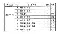
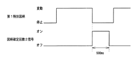
図7に示すように、出力ポート2は、情報端子盤34(を介してホールコンピュータ)に出力される信号の出力ポートである。出力ポート2から、始動口1信号、図柄確定回数2信号、図柄確定回数1信号、大当り1信号、大当り2信号、時短信号、大当り4信号、大当り3信号が出力される。なお、出力ポート2から出力される信号は、遊技制御処理の実行中に発生する制御情報の信号である。
As shown in FIG. 7, the
なお、出力ポート1,2は、図3に示されたI/Oポート部57の一部である。また、信号がオン状態になっているときが、「信号が出力されている」状態に相当する。
The
図8は、遊技制御手段における入力ポートのビット割り当ての例を示す説明図である。図8に示すように、入力ポート0のビット0〜7には、それぞれ、カウントスイッチ23、ゲートスイッチ32a、入賞口スイッチ39a,30a,29a,33a、第1始動口スイッチ13a、第2始動口スイッチ14aの検出信号が入力される。
FIG. 8 is an explanatory diagram showing an example of bit assignment of input ports in the game control means. As shown in FIG. 8, the
なお、入力ポート0は、図3に示されたI/Oポート部57の一部である。また、信号がオン状態になっているときが、「信号が入力されている」状態に相当する。
The
なお、図6〜図8に示された「論理」と逆の論理を用いてもよい。例えば、1がオン状態である入力信号を0をオン状態である入力信号にしてもよい。なお、図6〜図8に示されたポート(出力ポート、入力ポート)は、一時にアクセス可能なポート、すなわち、同一割込みでアクセス可能なポートである。 Note that logic opposite to the “logic” shown in FIGS. 6 to 8 may be used. For example, an input signal in which 1 is on may be an input signal in which 0 is on. 6 to 8 are ports that can be accessed at one time, that is, ports that can be accessed by the same interrupt.
図9は、情報端子盤の内部構成を示す回路図である。図9に示す情報端子盤34において、左側のコネクタCNは、図5に示した主基板31からの信号を伝達するケーブル343を接続するためのコネクタ341に相当し、右側のコネクタCN1〜CN8は、図5に示したホールコンピュータに対して信号を伝達するケーブル349を接続するためのコネクタ347に相当する。また、半導体リレー(PhotoMOSリレー)PC1〜PC8は、図5に示したドライバ回路345に相当する。
FIG. 9 is a circuit diagram showing the internal configuration of the information terminal board. In the
主基板31からのケーブル343がコネクタCNに接続されることにより、主基板31(遊技制御用マイクロコンピュータ560)から各種信号が情報端子盤34に入力される。具体的には、コネクタCNの端子「2」に始動口1信号が入力され、コネクタCNの端子「3」に図柄確定回数2信号が入力され、コネクタCNの端子「4」に図柄確定回数1信号が入力され、コネクタCNの端子「5」に大当り1信号が入力され、コネクタCNの端子「6」に大当り2信号が入力され、コネクタCNの端子「7」に時短信号が入力され、コネクタCNの端子「8」に大当り4信号が入力され、コネクタCNの端子「9」に大当り3信号が入力される。
When the cable 343 from the
図9に示すように、情報端子盤34では、コネクタCNの端子「1」に基準電位の信号線が接続され、その信号線が分岐して、各々の半導体リレーPC1〜PC8の入力端子「1」に接続されている。また、コネクタCNの端子「2」〜「9」に接続された信号線は、それぞれ、1KΩの抵抗R1〜R8を介して半導体リレーPC1〜PC8の入力端子「2」に接続されている。また、半導体リレーPC1〜PC8の出力端子「4」に接続された信号線は、それぞれ、コネクタCN1〜CN8の端子「1」に接続されている。また、半導体リレーPC1〜PC8の出力端子「3」に接続された信号線は、それぞれ、コネクタCN1〜CN8の端子「2」に接続されている。
As shown in FIG. 9, in the
半導体リレーPC1〜PC8では、入力端子に信号電流が流れると、入力側の発光素子(LED)が発光する。発光された光は、LEDと対向に設けられた光電素子(太陽電池)に透明シリコンを通って照射される。光を受けた光電素子は、光の量に応じて電圧に交換し、この電圧は制御回路を通って出力部のMOSFETゲートを充電する。光電素子より供給されるMOSFETゲート電圧が設定電圧値に達すると、MOSFETが導通状態になり、負荷をオンさせる。入力端子の信号電流が切れると、発光素子(LED)の発光が止まる。LEDの発光が止まると、光電素子の電圧が下がり、光電素子から供給される電圧が下がると制御回路により、MOSFETのゲート負荷を急速に放電させる。この制御回路によりMOSFETが非導通状態になり、負荷をオフさせる。 In the semiconductor relays PC1 to PC8, when a signal current flows through the input terminal, the light emitting element (LED) on the input side emits light. The emitted light is applied to the photoelectric element (solar cell) provided opposite to the LED through the transparent silicon. The photoelectric element that has received the light is exchanged for voltage according to the amount of light, and this voltage passes through the control circuit to charge the MOSFET gate of the output section. When the MOSFET gate voltage supplied from the photoelectric element reaches the set voltage value, the MOSFET becomes conductive and turns on the load. When the signal current at the input terminal is cut off, the light emitting element (LED) stops emitting light. When the light emission of the LED stops, the voltage of the photoelectric element decreases, and when the voltage supplied from the photoelectric element decreases, the gate load of the MOSFET is rapidly discharged by the control circuit. With this control circuit, the MOSFET is turned off and the load is turned off.
以上のような半導体リレーPC1〜PC8の動作により、入力側のコネクタCNから入力された信号が出力側のコネクタCN1〜CN8に伝達され、ホールコンピュータに対して出力される。具体的には、コネクタCN1から始動口1信号が出力され、コネクタCN2から図柄確定回数2信号が出力され、コネクタCN3から図柄確定回数1信号が出力され、コネクタCN4から大当り1信号が出力され、コネクタCN5から大当り2信号が出力され、コネクタCN6から時短信号が出力され、コネクタCN7から大当り4信号が出力され、コネクタCN8から大当り3信号が出力される。
By the operation of the semiconductor relays PC1 to PC8 as described above, signals input from the input side connector CN are transmitted to the output side connectors CN1 to CN8 and output to the hall computer. Specifically, a
上記のように、半導体リレーPC1〜PC8を情報端子盤34に設けたことにより、外部から遊技機内部への信号入力を防止することができ、その結果、不正行為を確実に防止することができる。なお、上記の例では、情報端子盤34に半導体リレーPC1〜PC8を設けていたが、半導体リレーPC1〜PC8ではなく、機械式のリレー等の他のリレー素子であってもよい。
As described above, by providing the semiconductor relays PC1 to PC8 on the
次に、遊技機の動作について説明する。図10は、主基板31における遊技制御用マイクロコンピュータ560が実行するメイン処理を示すフローチャートである。なお、ルーチンとは、プログラムにおいて、特定の処理を実行するための命令(コード)の集まりのことである。ある処理を行うための一連の命令を手順として記述したプロシージャや、与えられた情報に演算処理を加えて処理の結果を返す機能であるファンクション(関数)などがルーチンに分類される。特に個別のプログラムコードとして独立していなくても、ある分量のコードが特定の処理のために集中して配置されていれば、その部分はルーチンであるとみなすことができる。ルーチンはプログラム内での立場によって大きく2つに分けられ、プログラムを開始する際に最初に呼び出され、プログラム全体の進行を管理するルーチンを「メインルーチン」、プログラムの実行中に他のルーチンから呼び出されて動作するルーチンを「サブルーチン」と呼ぶ。
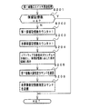
Next, the operation of the gaming machine will be described. FIG. 10 is a flowchart showing a main process executed by the
遊技機に対して電源が投入され電力供給が開始されると、リセット信号が入力されるリセット端子の入力レベルがハイレベルになり、遊技制御用マイクロコンピュータ560(具体的には、CPU56)は、プログラムの内容が正当か否か確認するための処理であるセキュリティチェック処理を実行した後、ステップS1以降のメイン処理を開始する。メイン処理において、CPU56は、まず、必要な初期設定を行う。
When power is supplied to the gaming machine and power supply is started, the input level of the reset terminal to which the reset signal is input becomes high level, and the gaming control microcomputer 560 (specifically, the CPU 56) After executing a security check process, which is a process for confirming whether the contents of the program are valid, the main process after step S1 is started. In the main process, the
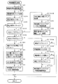
初期設定処理において、CPU56は、まず、割込禁止に設定する(ステップS1)。次に、割込モードを割込モード2に設定し(ステップS2)、スタックポインタにスタックポインタ指定アドレスを設定する(ステップS3)。そして、内蔵デバイスの初期化(内蔵デバイス(内蔵周辺回路)であるCTC(カウンタ/タイマ)およびPIO(パラレル入出力ポート)の初期化など)を行った後(ステップS4)、RAMをアクセス可能状態に設定する(ステップS5)。なお、割込モード2は、CPU56が内蔵する特定レジスタ(Iレジスタ)の値(1バイト)と内蔵デバイスが出力する割込ベクタ(1バイト:最下位ビット0)とから合成されるアドレスが、割込番地を示すモードである。
In the initial setting process, the
次いで、CPU56は、入力ポートを介して入力されるクリアスイッチ(例えば、電源基板に搭載されている。)の出力信号の状態を確認する(ステップS6)。その確認においてオンを検出した場合には、CPU56は、通常の初期化処理を実行する(ステップS10〜S15。S44,S45を含む。)。
Next, the
クリアスイッチがオンの状態でない場合には、遊技機への電力供給が停止したときにバックアップRAM領域のデータ保護処理(例えばパリティデータの付加等の電力供給停止時処理)が行われたか否か確認する(ステップS7)。そのような保護処理が行われていないことを確認したら、CPU56は初期化処理を実行する。バックアップRAM領域にバックアップデータがあるか否かは、例えば、電力供給停止時処理においてバックアップRAM領域に設定されるバックアップフラグの状態によって確認される。
If the clear switch is not on, check whether data protection processing of the backup RAM area (for example, power supply stop processing such as addition of parity data) was performed when power supply to the gaming machine was stopped (Step S7). When it is confirmed that such protection processing is not performed, the
電力供給停止時処理が行われたことを確認したら、CPU56は、バックアップRAM領域のデータチェックを行う(ステップS8)。この実施の形態では、データチェックとしてパリティチェックを行う。よって、ステップS8では、算出したチェックサムと、電力供給停止時処理で同一の処理によって算出され保存されているチェックサムとを比較する。不測の停電等の電力供給停止が生じた後に復旧した場合には、バックアップRAM領域のデータは保存されているはずであるから、チェック結果(比較結果)は正常(一致)になる。チェック結果が正常でないということは、バックアップRAM領域のデータが、電力供給停止時のデータとは異なっていることを意味する。そのような場合には、内部状態を電力供給停止時の状態に戻すことができないので、電力供給の停止からの復旧時でない電源投入時に実行される初期化処理を実行する。
When it is confirmed that the power supply stop process has been performed, the
チェック結果が正常であれば、CPU56は、遊技制御手段の内部状態と演出制御手段等の電気部品制御手段の制御状態を電力供給停止時の状態に戻すための遊技状態復旧処理(ステップS41〜S43の処理)を行う。具体的には、ROM54に格納されているバックアップ時設定テーブルの先頭アドレスをポインタに設定し(ステップS41)、バックアップ時設定テーブルの内容を順次作業領域(RAM55内の領域)に設定する(ステップS42)。作業領域はバックアップ電源によって電源バックアップされている。バックアップ時設定テーブルには、作業領域のうち初期化してもよい領域についての初期化データが設定されている。ステップS41およびS42の処理によって、作業領域のうち初期化してはならない部分については、保存されていた内容がそのまま残る。初期化してはならない部分とは、例えば、電力供給停止前の遊技状態を示すデータ(特別図柄プロセスフラグ、確変フラグ、時短フラグ、合算保留記憶数カウンタの値、時短回数カウンタの値など)、出力ポートの出力状態が保存されている領域(出力ポートバッファ)、未払出賞球数を示すデータが設定されている部分などである。
If the check result is normal, the
また、CPU56は、電力供給復旧時の初期化コマンドとしての停電復旧に関するコマンドを送信する(ステップS43)。そして、ステップS14に移行する。ここで、停電復旧に関するコマンドとしては、停電復旧画面を表示することを指定する停電復旧指定コマンド、停電発生時の遊技状態を指定する停電時遊技状態指定コマンド、停電発生時の合算保留記憶数を指定する合算保留記憶数指定コマンドが設けられている。なお、合算保留記憶数指定コマンドを送信する代わりに、第1保留記憶数をカウントする第1保留記憶数カウンタの値にもとづいて、第1保留記憶数を指定するコマンド(第1保留記憶数指定コマンド)を送信し、第2保留記憶数をカウントする第2保留記憶数カウンタの値にもとづいて、第2保留記憶数を指定するコマンド(第2保留記憶数指定コマンド)を送信するようにしてもよい。また、第1保留記憶数カウンタの値や第2保留記憶数カウンタの値が0のときは、それらのコマンドを送信しないようにしてもよい。 Moreover, CPU56 transmits the command regarding a power failure recovery as an initialization command at the time of electric power supply recovery (step S43). Then, the process proceeds to step S14. Here, as the commands related to power failure recovery, the power failure recovery specification command for specifying the display of the power failure recovery screen, the game state specification command for power failure specifying the gaming state at the time of power failure, and the total number of pending storage at the time of power failure A command for specifying the total pending storage number to be specified is provided. In addition, instead of transmitting the combined reserved memory number designation command, a command (first reserved memory number designation) that designates the first reserved memory number based on the value of the first reserved memory number counter that counts the first reserved memory number. Command), and a command for specifying the second reserved memory number (second reserved memory number designation command) is transmitted based on the value of the second reserved memory number counter for counting the second reserved memory number. Also good. Further, when the value of the first reserved memory number counter or the value of the second reserved memory number counter is 0, these commands may not be transmitted.
なお、この実施の形態では、バックアップフラグとチェックデータとの双方を用いてバックアップRAM領域のデータが保存されているか否か確認しているが、いずれか一方のみを用いてもよい。すなわち、バックアップフラグとチェックデータとのいずれかを、遊技状態復旧処理を実行するための契機としてもよい。 In this embodiment, it is confirmed whether the data in the backup RAM area is stored using both the backup flag and the check data. However, only one of them may be used. That is, either the backup flag or the check data may be used as an opportunity for executing the game state restoration process.
初期化処理では、CPU56は、まず、RAMクリア処理を行う(ステップS10)。なお、RAMクリア処理によって、所定のデータ(例えば大当り判定用乱数を生成するためのカウンタのカウント値のデータ)は0に初期化されるが、任意の値またはあらかじめ決められている値に初期化するようにしてもよい。また、RAM55の全領域を初期化せず、所定のデータ(例えば大当り判定用乱数を生成するためのカウンタのカウント値のデータ)をそのままにしてもよい。また、ROM54に格納されている初期化時設定テーブルの先頭アドレスをポインタに設定し(ステップS11)、初期化時設定テーブルの内容を順次作業領域に設定する(ステップS12)。
In the initialization process, the
ステップS11およびS12の処理によって、例えば、普通図柄判定用乱数カウンタ、普通図柄判定用バッファ、特別図柄バッファ、総賞球数格納バッファ、特別図柄プロセスフラグ、賞球中フラグ、球切れフラグ、払出停止フラグなど制御状態に応じて選択的に処理を行うためのフラグに初期値が設定される。 By the processing of steps S11 and S12, for example, a normal symbol determination random number counter, a normal symbol determination buffer, a special symbol buffer, a total prize ball number storage buffer, a special symbol process flag, an award ball flag, a ball out flag, and a payout stop An initial value is set to a flag such as a flag for selectively performing processing according to the control state.
また、CPU56は、サブ基板(主基板31以外のマイクロコンピュータが搭載された基板。)を初期化するための初期化指定コマンド(遊技制御用マイクロコンピュータ560が初期化処理を実行したことを示すコマンドでもある。)をサブ基板に送信する(ステップS13)。例えば、演出制御用マイクロコンピュータ100は、初期化指定コマンドを受信すると、演出表示装置9において、遊技機の制御の初期化がなされたことを報知するための画面表示、すなわち初期化報知を行う。
Further, the
さらに、CPU56は、異常報知禁止フラグをセットするとともに(ステップS44)、禁止期間タイマに禁止期間値に相当する値を設定する(ステップS45)。禁止期間値は、後述する異常入賞の報知を禁止する期間を示す値である。また、異常報知禁止フラグは、異常入賞の報知が禁止されていることを示すフラグであり、禁止期間タイマがタイムアウトするまでセット状態に維持される。よって、演出表示装置9において初期化報知が開始されてから所定期間は、異常入賞の報知の開始が禁止される。
Further, the
また、CPU56は、異常入賞数をカウントする異常入賞判定カウンタに閾値として「3」の値を設定する(ステップS46)。ステップS46で設定される閾値は、大当り遊技状態・小当り遊技状態以外の平常状態における特別可変入賞球装置20への遊技球の入賞を許容する値である。すなわち、平常状態においては、本来、特別可変入賞球装置20に遊技球が入賞するはずがないが、特別可変入賞球装置20内に遊技球が詰まり、大当り遊技状態・小当り遊技状態が終了した後に詰まりが解消したことによって遊技球の入賞が検出されるような場合も考えられる。また、ノイズ等によってカウントスイッチ23から検出信号が出力されたと誤検出されるとうな場合も考えられる。そこで、この実施の形態では、平常状態においてカウントスイッチ23が遊技球を検出したとしても、検出数が2回まで(つまり特別可変入賞球装置20への入賞数が2個まで)は、特別可変入賞球装置20への遊技球の入賞を許容すべく、ステップS46において閾値として「3」の値が設定されている。後述するように、カウントスイッチ23の検出数が3回になると、異常入賞が発生したと判定して異常報知を実行するための処理を実行する(図37のステップS588、S589参照)。なお、異常入賞判定カウンタは、RAM55の所定領域に形成されている。
In addition, the
また、CPU56は、乱数回路503を初期設定する乱数回路設定処理を実行する(ステップS14)。CPU56は、例えば、乱数回路設定プログラムに従って処理を実行することによって、乱数回路503にランダムRの値を更新させるための設定を行う。
Further, the
そして、ステップS15において、CPU56は、所定時間(例えば2ms)毎に定期的にタイマ割込がかかるように遊技制御用マイクロコンピュータ560に内蔵されているCTCのレジスタの設定を行なう。すなわち、初期値として例えば2msに相当する値が所定のレジスタ(時間定数レジスタ)に設定される。この実施の形態では、2ms毎に定期的にタイマ割込がかかるとする。
In step S15, the
初期化処理の実行(ステップS10〜S15)が完了すると、CPU56は、メイン処理で、表示用乱数更新処理(ステップS17)および初期値用乱数更新処理(ステップS18)を繰り返し実行する。表示用乱数更新処理および初期値用乱数更新処理を実行するときには割込禁止状態に設定し(ステップS16)、表示用乱数更新処理および初期値用乱数更新処理の実行が終了すると割込許可状態に設定する(ステップS19)。この実施の形態では、表示用乱数とは、変動パターンを決定するための乱数であり、表示用乱数更新処理とは、表示用乱数を発生するためのカウンタのカウント値を更新する処理である。また、初期値用乱数更新処理とは、初期値用乱数を発生するためのカウンタのカウント値を更新する処理である。この実施の形態では、初期値用乱数とは、普通図柄に関して当りとするか否か決定するための乱数を発生するためのカウンタ(普通図柄当り判定用乱数発生カウンタ)等の、カウント値の初期値を決定するための乱数である。後述する遊技の進行を制御する遊技制御処理(遊技制御用マイクロコンピュータ560が、遊技機に設けられている演出表示装置、可変入賞球装置、球払出装置等の遊技用の装置を、自身で制御する処理、または他のマイクロコンピュータに制御させるために指令信号を送信する処理、遊技装置制御処理ともいう)において、普通図柄当り判定用乱数のカウント値が1周(普通図柄当り判定用乱数の取りうる値の最小値から最大値までの間の数値の個数分歩進したこと)すると、そのカウンタに初期値が設定される。
When the execution of the initialization process (steps S10 to S15) is completed, the
タイマ割込が発生すると、CPU56は、図11に示すステップS20〜S35のタイマ割込処理を実行する。タイマ割込処理において、まず、電源断信号が出力されたか否か(オン状態になったか否か)を検出する電源断検出処理を実行する(ステップS20)。電源断信号は、例えば電源基板に搭載されている電圧低下監視回路が、遊技機に供給される電源の電圧の低下を検出した場合に出力する。そして、電源断検出処理において、CPU56は、電源断信号が出力されたことを検出したら、必要なデータをバックアップRAM領域に保存するための電力供給停止時処理を実行する。次いで、入力ドライバ回路58を介して、ゲートスイッチ32a、第1始動口スイッチ13a、第2始動口スイッチ14a、カウントスイッチ23、および入賞口スイッチ29a,30a,33a,39aの検出信号を入力し、それらの状態判定を行う(スイッチ処理:ステップS21)。
When the timer interrupt occurs, the
次に、CPU56は、第1特別図柄表示器8a、第2特別図柄表示器8b、普通図柄表示器10、第1特別図柄保留記憶表示器18a、第2特別図柄保留記憶表示器18b、普通図柄保留記憶表示器41の表示制御を行う表示制御処理を実行する(ステップS22)。第1特別図柄表示器8a、第2特別図柄表示器8bおよび普通図柄表示器10については、ステップS33,S34で設定される出力バッファの内容に応じて各表示器に対して駆動信号を出力する制御を実行する。
Next, the
また、CPU56は、正規の時期以外の時期において大入賞口に遊技球が入賞したことを検出した場合に異常入賞の報知を行わせるための処理を行う(ステップS23:異常入賞報知処理)。
Further, the
次に、遊技制御に用いられる大当り図柄決定用の乱数等の各判定用乱数を生成するための各カウンタのカウント値を更新する処理を行う(判定用乱数更新処理:ステップS24)。CPU56は、さらに、初期値用乱数および表示用乱数を生成するためのカウンタのカウント値を更新する処理を行う(初期値用乱数更新処理,表示用乱数更新処理:ステップS25,S26)。
Next, processing for updating the count value of each counter for generating random numbers for determination such as random numbers for determining jackpot symbols used for game control is performed (determination random number update processing: step S24). The
図12は、各乱数を示す説明図である。各乱数は、以下のように使用される。
(1)MR1:第1特別図柄および第2特別図柄のはずれ図柄(停止図柄)を決定する(はずれ図柄決定用)
(2)MR2:大当りを発生させるときの大当りの種別(「通常」「第1確変」「第2確変」「第3確変」「突確」)を決定する(大当り種別決定用)
(3)MR3:演出図柄(第1特別図柄および第2特別図柄)の変動パターン(変動時間)を決定する(変動パターン決定用)
(4)MR4:普通図柄にもとづく当りを発生させるか否か決定する(普通図柄当り判定用)
(5)MR5:MR4の初期値を決定する(MR4初期値決定用)
FIG. 12 is an explanatory diagram showing each random number. Each random number is used as follows.
(1) MR1: Determine the detachment symbol (stop symbol) of the first special symbol and the second special symbol (for detachment symbol determination)
(2) MR2: Determines the type of jackpot (“normal”, “first probability variation”, “second probability variation”, “third probability variation”, “surprise probability”) when generating the jackpot (for determining the jackpot type)
(3) MR3: Determine the variation pattern (variation time) of the production symbol (first special symbol and second special symbol) (for variation pattern determination)
(4) MR4: Determines whether or not to generate a hit based on a normal symbol (for normal symbol hit determination)
(5) MR5: Determines the initial value of MR4 (for determining MR4 initial value)
図11に示された遊技制御処理におけるステップS24では、遊技制御用マイクロコンピュータ560は、(2)の大当り種別決定用乱数、および(4)の普通図柄当り判定用乱数を生成するためのカウンタのカウントアップ(1加算)を行う。すなわち、それらが判定用乱数であり、それら以外の乱数が表示用乱数または初期値用乱数である。なお、遊技効果を高めるために、上記(1)〜(5)の乱数以外の乱数も用いるようにしてもよい。例えば、大当り種別決定用乱数の初期値を決定するためのMR2初期値用乱数を設けてもよい。そして、MR4初期値用乱数に加えてMR2初期値用乱数もステップS18,S25の初期値用乱数更新処理で更新するようにしてもよい。そのようにすれば、大当り決定時の大当り種別(特別図柄の大当り図柄)をよりランダムに決定することができ、特に確変図柄(例えば、「7」)や突然確変図柄(例えば、「5」)をよりランダムに発生させることができる。そのため、確変大当りをよりランダムに発生させることができ、遊技の興趣を高めることができる。また、この実施の形態では、大当り判定用乱数は遊技制御用マイクロコンピュータ560に内蔵されたハードウェア(乱数回路503)が生成する乱数であるが、大当り判定用乱数として、遊技制御用マイクロコンピュータ560によってプログラムにもとづいて生成されるソフトウェア乱数を用いてもよい。なお、乱数回路503を遊技制御用マイクロコンピュータ560に内蔵させずに、遊技制御用マイクロコンピュータ560とは別の回路であってもよい(遊技制御用マイクロコンピュータ560の外付けであってもよい)。
In step S24 in the game control process shown in FIG. 11, the
また、この実施の形態では、第1特別図柄の変動に関しても第2特別図柄の変動に関しても図12に示された乱数(特に、MR1,MR2,MR3)を用いるが、第1特別図柄の変動に関する乱数と第2特別図柄の変動に関する乱数とを別にしてもよい。 In this embodiment, the random numbers (particularly MR1, MR2, MR3) shown in FIG. 12 are used for both the first special symbol variation and the second special symbol variation. And the random number related to the variation of the second special symbol may be separated.
さらに、CPU56は、特別図柄プロセス処理を行う(ステップS27)。特別図柄プロセス処理では、第1特別図柄表示器8a、第2特別図柄表示器8bおよび大入賞口を所定の順序で制御するための特別図柄プロセスフラグに従って該当する処理を実行する。CPU56は、特別図柄プロセスフラグの値を、遊技状態に応じて更新する。
Further, the
次いで、普通図柄プロセス処理を行う(ステップS28)。普通図柄プロセス処理では、CPU56は、普通図柄表示器10の表示状態および可変入賞球装置15の開閉状態を所定の順序で制御するための普通図柄プロセスフラグに従って該当する処理を実行する。CPU56は、普通図柄プロセスフラグの値を、遊技状態に応じて更新する。
Next, normal symbol process processing is performed (step S28). In the normal symbol process, the
また、CPU56は、演出制御用マイクロコンピュータ100に演出制御コマンドを送出する処理を行う(演出制御コマンド制御処理:ステップS29)。
Further, the
さらに、CPU56は、例えばホールコンピュータに出力される信号(具体的には、出力ポート2から出力される始動口1信号、図柄確定回数2信号、図柄確定回数1信号、大当り1信号、大当り2信号、時短信号、大当り4信号、大当り3信号)を出力する情報出力処理を行う(ステップS30)。
Further, the
また、CPU56は、第1始動口スイッチ13a、第2始動口スイッチ14a、カウントスイッチ23および入賞口スイッチ29a,30a,33a,39aの検出信号にもとづく賞球個数の設定などを行う賞球処理を実行する(ステップS31)。具体的には、第1始動口スイッチ13a、第2始動口スイッチ14a、カウントスイッチ23および入賞口スイッチ29a,30a,33a,39aのいずれかがオンしたことにもとづく入賞検出に応じて、払出制御基板37に搭載されている払出制御用マイクロコンピュータに賞球個数を示す払出制御コマンド(賞球個数信号)を出力する。払出制御用マイクロコンピュータは、賞球個数を示す払出制御コマンドに応じて球払出装置97を駆動する。
Further, the
この実施の形態では、出力ポートの出力状態に対応したRAM領域(出力ポートバッファ)が設けられているのであるが、CPU56は、出力ポートの出力状態に対応したRAM領域におけるソレノイドのオン/オフに関する内容を出力ポートに出力する(ステップS32:出力処理)。
In this embodiment, a RAM area (output port buffer) corresponding to the output state of the output port is provided. However, the
また、CPU56は、後述する変動パターン設定処理でセットされる開始フラグや特別図柄プロセスフラグの値に応じて、特別図柄の演出表示を行うための特別図柄表示制御データを特別図柄表示制御データ設定用の出力バッファに設定する特別図柄表示制御処理を行う(ステップS33)。CPU56は、例えば、特別図柄プロセス処理で開始フラグがセットされると終了フラグがセットされるまで、変動速度が1コマ/0.2秒であれば、0.2秒が経過する毎に、出力バッファに設定される表示制御データの値を+1する。なお、開始フラグおよび終了フラグを用いずに、CPU56は、特別図柄プロセスフラグの値にもとづいて表示制御データの値を更新するようにしてもよい。例えば、CPU56は、特別図柄プロセスフラグの値が変動パターン設定処理に対応した値(この実施の形態では1)となると、特別図柄プロセスフラグの値が特別図柄停止処理に対応した値(この実施の形態では4)となるまで、0.2秒が経過する毎に表示制御データの値を+1するようにしてもよい。また、CPU56は、出力バッファに設定された表示制御データに応じて、ステップS22において駆動信号を出力することによって、第1特別図柄表示器8aおよび第2特別図柄表示器8bにおける第1特別図柄および第2特別図柄の可変表示を実行する。
Further, the
なお、CPU56は、例えば、後述する特別図柄ポインタを確認し、第1特別図柄と第2特別図柄のうち特別図柄ポインタが示す特別図柄に対応する方の特別図柄表示器8a,8bにおける可変表示を実行する。
For example, the
さらに、CPU56は、普通図柄プロセスフラグの値に応じて普通図柄の演出表示を行うための普通図柄表示制御データを普通図柄表示制御データ設定用の出力バッファに設定する普通図柄表示制御処理を行う(ステップS34)。CPU56は、例えば、普通図柄の変動に関する開始フラグがセットされると終了フラグがセットされるまで、普通図柄の変動速度が0.2秒ごとに表示状態(「○」および「×」)を切り替えるような速度であれば、0.2秒が経過する毎に、出力バッファに設定される表示制御データの値(例えば、「○」を示す1と「×」を示す0)を切り替える。なお、開始フラグおよび終了フラグを用いずに、CPU56は、普通図柄プロセスフラグの値にもとづいて表示制御データの値を切り替えるようにしてもよい。例えば、普通図柄プロセス処理において、CPU56は、普通図柄プロセスフラグの値にもとづいて、ゲート通過記憶数を確認して普通図柄を当りとするか否かや普通図柄の停止図柄を決定する普通図柄通常処理、普通図柄の変動中の各種処理を実行する普通図柄変動処理、普通図柄を停止表示する普通図柄停止処理、普通図柄が当りとなった後に普通電動役物(可変入賞球装置15)の開閉制御を行う普通電動役物作動処理を実行する。この場合、例えば、CPU56は、普通図柄プロセスフラグの値が普通図柄変動処理に対応した値(例えば1)となると、普通図柄プロセスフラグの値が普通図柄停止処理に対応した値(例えば2)となるまで、0.2秒が経過する毎に表示制御データの値を+1するようにしてもよい。また、CPU56は、出力バッファに設定された表示制御データに応じて、ステップS22において駆動信号を出力することによって、普通図柄表示器10における普通図柄の演出表示を実行する。
Further, the
その後、割込許可状態に設定し(ステップS35)、処理を終了する。 Thereafter, the interrupt permission state is set (step S35), and the process is terminated.
以上の制御によって、この実施の形態では、遊技制御処理は2ms毎に起動されることになる。なお、遊技制御処理は、タイマ割込処理におけるステップS21〜S34(ステップS30を除く。)の処理に相当する。また、この実施の形態では、タイマ割込処理で遊技制御処理が実行されているが、タイマ割込処理では例えば割込が発生したことを示すフラグのセットのみがなされ、遊技制御処理はメイン処理において実行されるようにしてもよい。 With the above control, in this embodiment, the game control process is started every 2 ms. The game control process corresponds to the processes of steps S21 to S34 (excluding step S30) in the timer interrupt process. In this embodiment, the game control process is executed by the timer interrupt process. However, in the timer interrupt process, for example, only a flag indicating that an interrupt has occurred is set, and the game control process is performed by the main process. May be executed.
図13は、大当り判定テーブルおよび大当り種別決定テーブルを示す説明図である。大当り判定テーブルとは、0〜65535の数値範囲内で更新されるランダムR(大当り判定用乱数)と比較される大当り判定値および小当り判定値が設定されているテーブルである(図13(A)(B))。大当り判定テーブルには、通常状態または時短状態において用いられる通常時大当り判定テーブル(図13(A)参照)と、確変状態において用いられる確変時大当り判定テーブル(図13(B)参照)とがある。図13(A),(B)の左欄に記載されている数値が大当り判定値および小当り判定値である。CPU56は、ランダムRの値と大当り判定値とを比較し、ランダムRの値がいずれかの大当り判定値と一致すると、大当りとすることに決定する。また、CPU56は、ランダムRの値と小当り判定値とを比較し、ランダムRの値がいずれかの小当り判定値と一致すると、小当りとすることに決定する。
FIG. 13 is an explanatory diagram showing a jackpot determination table and a jackpot type determination table. The big hit determination table is a table in which a big hit determination value and a small hit determination value to be compared with random R (random number for big hit determination) updated within a numerical range of 0 to 65535 are set (FIG. 13A). (B)). The big hit determination table includes a normal big hit determination table (see FIG. 13A) used in a normal state or a short time state, and a probable change big hit determination table (see FIG. 13B) used in a probability change state. . The numerical values described in the left column of FIGS. 13A and 13B are the big hit determination value and the small hit determination value. The
また、大当り種別決定テーブルとは、大当り種別決定用乱数(MR2)と比較される各大当り種別(「通常」「第1確変」「第2確変」「第3確変」「突確」)に割り振られる判定値が設定されているテーブルである(図8(C))。ランダムRにもとづいて大当りとすることに決定された場合には、大当り種別決定用乱数にもとづいて大当り種別が決定される。 The jackpot type determination table is assigned to each jackpot type (“normal”, “first probability variation”, “second probability variation”, “third probability variation”, “surprise”) compared to the jackpot type determination random number (MR2). This is a table in which determination values are set (FIG. 8C). When it is determined to win the jackpot based on the random R, the jackpot type is determined based on the jackpot type determining random number.
ここで、「通常」は、図柄の変動停止時に非確変図柄(カス図柄)が導出表示されることにより発生する通常大当り(非確変大当り)を意味する。「第1確変」は、図柄の変動停止時に確変図柄が導出表示されることにより発生する確変大当り(第1確変大当り)を意味する。「第2確変」は、図柄の変動中に非確変図柄が仮停止された後に、変動中昇格演出が実行されることにより発生する確変大当り(第2確変大当り)を意味する。「第3確変」は、図柄の変動停止時に非確変図柄が導出表示されるが、大当り遊技中の所定のタイミングにおいて大当り中昇格演出が実行されることにより発生する確変大当り(第3確変大当り)を意味する。「突確」は2ラウンドの突然確変大当りを意味する。 Here, “normal” means a normal big hit (non-probable change big hit) that is generated when a non-probable variation symbol (cass symbol) is derived and displayed when the symbol fluctuation is stopped. The “first probability variation” means a probability variation big hit (first probability variation big hit) generated by the probability variation symbol being derived and displayed when the symbol variation is stopped. The “second probability variation” means a probability variation big hit (second probability variation big hit) that is generated when a non-probability variation symbol is temporarily stopped during a symbol variation and then a fluctuating promotion effect is executed. “3rd probability variation” is a non-probability variation symbol derived and displayed when symbol variation is stopped, but a probability variation big hit (third probability variation big hit) that occurs when a big hit promotion promotion effect is executed at a predetermined timing during a big hit game. Means. “Accuracy” means two rounds of sudden and promising big hits.
大当り種別と特別図柄の大当り図柄とは対応している。具体的には、大当り種別として「通常大当り」が決定されたときは、特別図柄の停止図柄(確定特別図柄)が「3」となる。大当り種別として「確変大当り(第1確変大当り、第2確変大当り、第3確変大当り)」が決定されたときは、特別図柄の停止図柄(確定特別図柄)が「7」となる。大当り種別として「突然確変大当り」が決定されたときは、特別図柄の停止図柄(確定特別図柄)が「5」となる。なお、この実施の形態では、図13(C)に示すように、第1特別図柄用の大当り種別決定テーブルと、第2特別図柄用の大当り種別決定テーブルとは別々に設け、第2特別図柄用の大当り種別決定テーブルには、大当り種別「突確」に判定値が割り振られていない。したがって、第2始動入賞が発生にもとづき大当りが発生したときは、大当り種別として「突確」が決定されないことになる。ただし、第2始動入賞が発生にもとづき大当りが発生したときも、大当り種別として「突確」が決定されるように判定値を割り振るようにしてもよい。また、第1特別図柄用のテーブルと第2特別図柄用のテーブルに分けずに、一つの大当り種別決定テーブルを用いて第1特別図柄および第2特別図柄の大当り種別を決定するようにしもよい。 The jackpot type and the special jackpot symbol correspond to each other. Specifically, when “normal jackpot” is determined as the jackpot type, the special symbol stop symbol (determined special symbol) is “3”. When “probability big hit (first probability variation big hit, second probability variation big hit, third probability variation big hit)” is determined as the big hit type, the special symbol stop symbol (determined special symbol) becomes “7”. When “suddenly promising big hit” is determined as the big hit type, the special symbol stop symbol (determined special symbol) is “5”. In this embodiment, as shown in FIG. 13C, the jackpot type determination table for the first special symbol and the jackpot type determination table for the second special symbol are provided separately, and the second special symbol is provided. In the big hit type determination table, no determination value is assigned to the big hit type “surprise”. Therefore, when a big hit has occurred based on the occurrence of the second start winning prize, the “surprise” is not determined as the big hit type. However, even when a big hit occurs based on the occurrence of the second start winning prize, a determination value may be assigned so that “surprise” is determined as the big hit type. Further, instead of dividing the table for the first special symbol and the table for the second special symbol, the jackpot type of the first special symbol and the second special symbol may be determined using one jackpot type determination table. .
なお、ランダムRにもとづいて小当りとすることに決定された場合には、自動的に(大当り種別決定用乱数を用いることなく)特別図柄の停止図柄は「1」と決定される。また、ランダムRにもとづいてはずれとすることに決定された場合には、はずれ図柄決定用乱数にもとづいて特別図柄の停止図柄として「2」「4」「6」「8」「9」「−」のいずれかが決定される。 If it is determined to be a small hit based on the random R, the special symbol stop symbol is automatically determined to be “1” (without using the big hit type determining random number). If it is decided to make a deviation based on the random R, “2”, “4”, “6”, “8”, “9”, “−” are used as the special symbol stop symbols based on the random symbol for determining the loss symbol. "Is determined.
なお、飾り図柄の停止図柄は、2つのLEDのうち、いずれか一方が大当り図柄・小当り図柄(大当り・小当り共通の図柄)であり、他方がはずれ図柄である。また、演出図柄の停止図柄は、CPU56にて決定された表示結果(第1確変大当り、第2確変大当り、第3確変大当り、通常大当り、突然確変大当り、小当り、はずれ)を指定する表示結果特定コマンドにもとづいて演出制御用CPU101によって決定される。
In addition, as for the stop symbol of the decorative symbol, one of the two LEDs is a big hit symbol / small hit symbol (a symbol common to the big hit / small hit), and the other is an off symbol. Further, the stop symbol of the production symbol is a display result for designating the display results (first probability variation big hit, second probability variation big hit, third probability variation big hit, normal big hit, sudden probability variation big hit, small hit, off) determined by the
このように、この実施の形態では、特別図柄および飾り図柄の変動表示の表示結果として、第1確変大当り、第2確変大当り、第3確変大当り、通常大当り、突然確変大当り、小当りまたははずれのいずれかに決定される。CPU56は、所定の時期に、乱数回路503のカウント値を抽出して抽出値を大当り判定用乱数値とするのであるが、大当り判定用乱数値が図13に示す大当り判定値または小当り判定値に一致すると、第1特別図柄および第2特別図柄に関して大当りまたは小当りとすることに決定する。
As described above, in this embodiment, the display result of the variation display of the special symbol and the decorative symbol includes the first probability variation big hit, the second probability variation big hit, the third probability variation big hit, the normal big hit, the sudden probability variation big hit, the small hit or the out of order. Decide on either. The
図14は、この実施の形態で用いられる変動パターンの一例を示す説明図である。図14において、「EXT」とは、2バイト構成の演出制御コマンドにおける2バイト目のEXTデータを示す。また、「時間」は特別図柄の変動時間(識別情報の可変表示期間)を示す。 FIG. 14 is an explanatory diagram showing an example of a variation pattern used in this embodiment. In FIG. 14, “EXT” indicates EXT data of the second byte in the effect control command having a two-byte structure. “Time” indicates the variation time of the special symbol (variable display period of identification information).
この例では、各変動パターンは、特別図柄(演出図柄)の停止図柄が「はずれ図柄」となる場合の変動パターンと、特別図柄(演出図柄)の停止図柄が「大当り図柄」となる場合の変動パターンと、特別図柄(演出図柄)の停止図柄が「突然確変大当り図柄」となる場合の変動パターンと、特別図柄(演出図柄)の停止図柄が「小当り図柄」となる場合の変動パターンとが設けられている。 In this example, each variation pattern has a variation pattern when the stop symbol of the special symbol (effect symbol) is “out of symbol” and a variation when the stop symbol of the special symbol (effect symbol) is “big hit symbol”. A variation pattern when the stop symbol of the special symbol (directing symbol) is “suddenly probable big hit symbol” and a variation pattern when the stop symbol of the special symbol (directing symbol) is “small hit symbol” Is provided.
はずれの変動パターンとして、リーチを伴わない通常変動の変動パターンと、リーチを伴わない短縮変動の変動パターンと、ノーマルリーチ(単純なリーチ態様)を伴う変動パターンと、ロングリーチを伴う変動パターンと、スーパーリーチAを伴う変動パターンと、スーパーリーチBを伴う変動パターンと、スーパーリーチCを伴う変動パターンとが設けられている。 As fluctuation patterns of outliers, fluctuation patterns of normal fluctuations without reach, fluctuation patterns of shortening fluctuations without reach, fluctuation patterns with normal reach (simple reach mode), fluctuation patterns with long reach, and super A variation pattern with reach A, a variation pattern with super reach B, and a variation pattern with super reach C are provided.
大当りの変動パターンとして、ノーマルリーチを伴う変動パターンと、ロングリーチを伴う変動パターンと、スーパーリーチAを伴う変動パターンと、スーパーリーチBを伴う変動パターンと、スーパーリーチCを伴う変動パターンと、スーパーリーチDを伴う変動パターンと、スーパーリーチDを伴う変動パターンとが設けられている。 The jackpot variation pattern includes a variation pattern with normal reach, a variation pattern with long reach, a variation pattern with super reach A, a variation pattern with super reach B, a variation pattern with super reach C, and a super reach. A variation pattern with D and a variation pattern with super reach D are provided.
突然確変大当りの変動パターンとして、突然確変用の特別変動の変動パターンのみ設けられている。また、小当り専用の変動パターンとして、小当り用の特別変動の変動パターンのみ設けられている。 As a variation pattern for the sudden probability variation big hit, only a variation pattern of a special variation for sudden probability variation is provided. Further, only a special variation pattern for small hits is provided as a small hit dedicated variation pattern.
次に、遊技制御用マイクロコンピュータ560から演出制御用マイクロコンピュータ100に対する制御コマンドの送出方式について説明する。図15は、主基板31から演出制御基板80に送信される演出制御コマンドの信号線を示す説明図である。図15に示すように、この実施の形態では、演出制御コマンドは、演出制御信号CD0〜CD7の8本の信号線で主基板31から中継基板77を介して演出制御基板80に送信される。また、主基板31と演出制御基板80との間には、取込信号(演出制御INT信号)を送信するための演出制御INT信号の信号線も配線されている。
Next, a method for sending a control command from the
この実施の形態では、演出制御コマンドは2バイト構成であり、1バイト目はMODE(コマンドの分類)を表し、2バイト目はEXT(コマンドの種類)を表す。MODEデータの先頭ビット(ビット7)は必ず「1」に設定され、EXTデータの先頭ビット(ビット7)は必ず「0」に設定される。なお、そのようなコマンド形態は一例であって他のコマンド形態を用いてもよい。例えば、1バイトや3バイト以上で構成される制御コマンドを用いてもよい。 In this embodiment, the presentation control command has a 2-byte structure, the first byte represents MODE (command classification), and the second byte represents EXT (command type). The first bit (bit 7) of the MODE data is always set to “1”, and the first bit (bit 7) of the EXT data is always set to “0”. Note that such a command form is an example, and other command forms may be used. For example, a control command composed of 1 byte or 3 bytes or more may be used.
図16に示すように、演出制御コマンドの8ビットの演出制御コマンドデータは、演出制御INT信号に同期して出力される。演出制御基板80に搭載されている演出制御用マイクロコンピュータ100は、演出制御INT信号が立ち上がったことを検知して、割込処理によって1バイトのデータの取り込み処理を開始する。従って、演出制御用マイクロコンピュータ100から見ると、演出制御INT信号は、演出制御コマンドデータの取り込みの契機となる信号(取り込みの指示信号)に相当する。
As shown in FIG. 16, the 8-bit effect control command data of the effect control command is output in synchronization with the effect control INT signal. The
演出制御コマンドは、演出制御用マイクロコンピュータ100が認識可能に1回だけ送出される。認識可能とは、この例では、演出制御INT信号のレベルが変化することであり、認識可能に1回だけ送出されるとは、例えば演出制御コマンドデータの1バイト目および2バイト目のそれぞれに応じて演出制御INT信号が1回だけパルス状(矩形波状)に出力されることである。なお、演出制御INT信号は図16に示された極性と逆極性であってもよい。
The effect control command is sent only once so that the
図17および図18は、遊技制御用マイクロコンピュータ560が送信する演出制御コマンドの内容の一例を示す説明図である。図17に示す例において、コマンド80XX(H)は、特別図柄の可変表示に対応して飾り図柄表示器および演出表示装置9において可変表示される飾り図柄および演出図柄の変動パターンを指定する演出制御コマンド(変動パターンコマンド)である。なお、「(H)」は16進数であることを示す。また、変動パターンを指定する演出制御コマンドは、変動開始を指定するためのコマンドでもある。従って、演出制御用マイクロコンピュータ100は、コマンド80XX(H)のいずれかを受信すると、飾り図柄表示器および演出表示装置9において飾り図柄および演出図柄の可変表示を開始するように制御する。
FIGS. 17 and 18 are explanatory diagrams showing an example of the contents of the effect control command transmitted by the
コマンド8C01(H)〜8C07(H)は、大当り、小当りまたははずれのいずれとするか、および大当り遊技の種類(大当りの種別)を示す演出制御コマンドである。演出制御用マイクロコンピュータ100は、コマンド8C01(H)〜8C07(H)の受信に応じて飾り図柄および演出図柄の表示結果を決定するので、コマンド8C01(H)〜8C07(H)を表示結果特定コマンドという。
The commands 8C01 (H) to 8C07 (H) are effect control commands that indicate whether a big hit, a small hit or a loss, and a type of big hit game (a type of big hit). The
コマンド8D01(H)は、第1特別図柄の可変表示(変動)を開始することを示す演出制御コマンド(第1図柄変動指定コマンド)である。コマンド8D02(H)は、第2特別図柄の可変表示(変動)を開始することを示す演出制御コマンド(第2図柄変動指定コマンド)である。第1図柄変動指定コマンドと第2図柄変動指定コマンドとを特別図柄特定コマンド(または図柄変動指定コマンド)と総称することがある。 Command 8D01 (H) is an effect control command (first symbol variation designation command) indicating that variable display (variation) of the first special symbol is started. Command 8D02 (H) is an effect control command (second symbol variation designation command) indicating that variable display (variation) of the second special symbol is started. The first symbol variation designation command and the second symbol variation designation command may be collectively referred to as a special symbol specifying command (or symbol variation designation command).
コマンド8F00(H)は、飾り図柄および演出図柄の可変表示(変動)を終了して表示結果(停止図柄)を導出表示することを示す演出制御コマンド(図柄確定指定コマンド)である。演出制御用マイクロコンピュータ100は、図柄確定指定コマンドを受信すると、飾り図柄および演出図柄の可変表示(変動)を終了して表示結果を導出表示する。なお、この実施の形態では、第1特別図柄に対応する飾り図柄および演出図柄の変動表示を停止する場合と、第2特別図柄に対応する飾り図柄および演出図柄の変動表示を停止する場合とで共通の図柄確定指定コマンドを送信する場合を示すが、第1特別図柄に対応する変動表示を停止する場合と第2特別図柄に対応する変動表示を終了する場合とで別々の図柄確定指定コマンド(例えば、第1図柄確定指定コマンド、第2図柄確定指定コマンド)を送信するようにしてもよい。
Command 8F00 (H) is an effect control command (symbol confirmation designation command) indicating that the variable display (fluctuation) of decorative symbols and effect symbols is terminated and the display result (stop symbol) is derived and displayed. When receiving the symbol confirmation designation command, the
コマンド9000(H)は、遊技機に対する電力供給が開始されたときに送信される、初期画面を表示することを指定する演出制御コマンド(初期化指定コマンド:電源投入指定コマンド)である。コマンド9200(H)は、遊技機に対する電力供給が再開されたときに送信される、停電復旧画面を表示することを指定する演出制御コマンド(停電復旧指定コマンド)である。遊技制御用マイクロコンピュータ560は、遊技機に対する電力供給が開始されたときに、バックアップRAMにデータが保存されている場合には、停電復旧指定コマンドを送信し、そうでない場合には、初期化指定コマンドを送信する。
Command 9000 (H) is an effect control command (initialization designation command: power-on designation command) for designating display of an initial screen, which is transmitted when power supply to the gaming machine is started. Command 9200 (H) is an effect control command (power failure recovery designation command) that designates the display of a power failure recovery screen that is transmitted when power supply to the gaming machine is resumed. When the power supply to the gaming machine is started, the
なお、CPU56は、停電から復旧したときに電源バックアップされている遊技状態を示すフラグ(確変フラグ、時短フラグなど)を確認し、遊技状態に応じて異なる停電復旧画面を表示することを指定する停電復旧指定コマンドを送信するようにしてもよい。具体的には、停電から復旧したときの遊技状態が通常状態であればコマンド9200(H)が送信され、停電から復旧したときの遊技状態が確変状態であればコマンド9201(H)が送信され、停電から復旧したときの遊技状態が時短状態であればコマンド9202(H)が送信され、停電から復旧したときの遊技状態がチャンスモード状態であればコマンド9203(H)が送信されるようにしてもよい。この場合、演出制御用CPU101は、CPU56からの停電復旧指定コマンドにもとづいて遊技状態に応じて異なる停電復旧画面を演出表示装置9に表示する。
Note that the
コマンド93XX(H)は、停電発生時の遊技状態を指定する停電時遊技状態指定コマンドである。CPU56は、停電から復旧したときに電源バックアップされている遊技状態を示すフラグ(確変フラグ、時短フラグなど)を確認し、遊技状態に応じた停電時遊技状態指定コマンドを送信する。なお、XXには、遊技状態に応じた値が設定される。具体的には、停電から復旧したときの遊技状態が通常状態であればコマンド9300(H)が送信され、停電から復旧したときの遊技状態が確変状態であればコマンド9301(H)が送信され、停電から復旧したときの遊技状態が時短状態であればコマンド9302(H)が送信され、停電から復旧したときの遊技状態がチャンスモード状態であればコマンド9303(H)が送信される。この場合、演出制御用CPU101は、CPU56からの停電時遊技状態指定コマンドにもとづいて遊技状態に応じた背景(背景画像、背景色など)を演出表示装置9に表示する。
Command 93XX (H) is a power failure gaming state designation command for designating a gaming state when a power failure occurs. The
コマンド9500(H)は、遊技状態が通常状態であるときの背景を表示することを指定する演出制御コマンド(通常状態背景指定コマンド)である。コマンド9501(H)は、遊技状態が確変状態であるときの背景を表示することを指定する演出制御コマンド(確変状態背景指定コマンド)である。コマンド9502(H)は、遊技状態が時短状態であるときの背景を表示することを指定する演出制御コマンド(時短状態背景指定コマンド)である。コマンド9503(H)は、遊技状態がチャンスモード状態であるときの背景を表示することを指定する演出制御コマンド(チャンスモード状態背景指定コマンド)である。なお、コマンド9500(H)〜9503(H)を背景指定コマンドという。 Command 9500 (H) is an effect control command (normal state background designation command) for designating display of a background when the gaming state is the normal state. The command 9501 (H) is an effect control command (probability change state background designation command) for designating display of a background when the gaming state is a probability change state. Command 9502 (H) is an effect control command (time-short state background designation command) for designating display of a background when the gaming state is the time-short state. Command 9503 (H) is an effect control command (chance mode state background designation command) for designating display of a background when the gaming state is the chance mode state. Commands 9500 (H) to 9503 (H) are referred to as background designation commands.
なお、CPU56がチャンスモード状態であるか否かを管理しない場合には、CPU56は遊技状態がチャンスモード状態であることを示すチャンスモード状態背景指定コマンド(9503(H))を送信する必要がない。
When the
コマンド9F00(H)は、客待ちデモンストレーションを指定する演出制御コマンド(客待ちデモ指定コマンド)である。 Command 9F00 (H) is an effect control command (customer waiting demonstration designation command) for designating a customer waiting demonstration.
図18に示す例において、コマンドA001〜A004(H)は、ファンファーレ画面を表示すること、すなわち大当り遊技(または小当り遊技)の開始を指定する演出制御コマンド(大当り開始指定コマンド:ファンファーレ指定コマンド)である。大当り開始指定コマンドには、大当りの種類に応じて、大当り開始1指定〜大当り開始4指定コマンドがある。なお、このうち、大当り開始1指定コマンドA001(H)は、通常大当り(非確変大当り)遊技の開始を指定する演出制御コマンドである。大当り開始2指定コマンドA002(H)は、小当り遊技の開始を指定する演出制御コマンドである。大当り開始3指定コマンドA003(H)は、確変大当り遊技の開始を指定する演出制御コマンドである。大当り開始4指定コマンドA004(H)は、突然確変大当り(2ラウンド大当り)遊技の開始を指定する演出制御コマンドである。 In the example shown in FIG. 18, the commands A001 to A004 (H) display a fanfare screen, that is, an effect control command for designating the start of a big hit game (or a small hit game) (big hit start designation command: fanfare designation command) It is. The jackpot start designation commands include jackpot start 1 designation to jackpot start 4 designation commands depending on the type of jackpot. Of these, the big hit start 1 designation command A001 (H) is an effect control command for designating the start of a normal big hit (non-probability variable big hit) game. The big hit start 2 designation command A002 (H) is an effect control command for designating the start of a small hit game. The big hit start 3 designation command A003 (H) is an effect control command for designating the start of a probable big hit game. The big hit start 4 designation command A004 (H) is an effect control command for designating the start of a sudden probability change big hit (two round big hit) game.
コマンドA1XX(H)は、XXで示す回数目(ラウンド)の大入賞口開放中の表示を示す演出制御コマンド(大入賞口開放中指定コマンド)である。A2XX(H)は、XXで示す回数目(ラウンド)の大入賞口閉鎖を示す演出制御コマンド(大入賞口開放後指定コマンド)である。 The command A1XX (H) is an effect control command (special command during opening of a big winning opening) indicating a display during the opening of the big winning opening for the number of times (round) indicated by XX. A2XX (H) is an effect control command (designation command after opening the big winning opening) indicating the closing of the big winning opening for the number of times (round) indicated by XX.
コマンドA301(H)は、非確変大当り終了画面を表示すること、すなわち大当り遊技の終了を指定するとともに、非確変大当り(通常大当り)であったことを指定する演出制御コマンド(大当り終了1指定コマンド:エンディング1指定コマンド)である。コマンドA302(H)は、確変大当り終了画面を表示すること、すなわち大当り遊技の終了を指定するとともに、確変大当りであったことを指定する演出制御コマンド(大当り終了2指定コマンド:エンディング2指定コマンド)である。コマンドA303(H)は、突然確変大当り終了画面を表示すること、すなわち大当り遊技の終了を指定するとともに、突然確変大当りであったことを指定する演出制御コマンド(大当り終了3指定コマンド:エンディング3指定コマンド)である。なお、この実施の形態では、小当り終了画面を表示すること、すなわち小当り遊技の終了を指定する演出制御コマンドを設けていないが、そのようなコマンドを設けてもよい。
Command A301 (H) is an effect control command for displaying the non-probability variable big hit end screen, that is, specifying the end of the big hit game, and specifying that it is a non-probable variable big hit (normal big hit) (a
コマンドC000(H)は、第1始動入賞があったことを指定する演出制御コマンド(第1始動入賞指定コマンド)である。コマンドC100(H)は、第2始動入賞があったことを指定する演出制御コマンド(第2始動入賞指定コマンド)である。第1始動入賞指定コマンドと第2始動入賞指定コマンドとを、始動入賞指定コマンドと総称することがある。 The command C000 (H) is an effect control command (first start winning designation command) that designates that the first start winning has been won. The command C100 (H) is an effect control command (second start winning designation command) for designating that the second starting win has been won. The first start prize designation command and the second start prize designation command may be collectively referred to as a start prize designation command.
コマンドC2XX(H)は、第1保留記憶数と第2保留記憶数との合計である合計数(合算保留記憶数)を指定する演出制御コマンド(合算保留記憶数指定コマンド)である。コマンドC2XX(H)における「XX」が、合算保留記憶数を示す。なお、この実施の形態では、合算保留記憶数指定コマンドコマンドC2XX(H)が遊技制御の実行中のみならず停電復旧時にも送信される(ステップS43参照)。コマンドC300(H)は、合算保留記憶数を1減算することを指定する演出制御コマンド(合算保留記憶数減算指定コマンド)である。この実施の形態では、遊技制御用マイクロコンピュータ560は、合算保留記憶数を減算する場合には合算保留記憶数減算指定コマンドを送信するが、合算保留記憶数減算指定コマンドを使用せず、合算保留記憶数を減算するときに、減算後の合算保留記憶数を合算保留記憶数指定コマンドで指定するようにしてもよい。
The command C2XX (H) is an effect control command (total pending storage number designation command) that designates the total number (total pending storage number) that is the sum of the first reserved memory number and the second reserved memory number. “XX” in the command C2XX (H) indicates the total pending storage number. In this embodiment, the total pending storage number designation command command C2XX (H) is transmitted not only during the execution of the game control but also when the power failure is restored (see step S43). The command C300 (H) is an effect control command (total pending storage count subtraction designation command) that designates that the total pending storage count is decremented by one. In this embodiment, the
コマンドD001(H)は、異常入賞の報知を指示する演出制御コマンド(異常入賞指定コマンド)である。 Command D001 (H) is an effect control command (abnormal winning designation command) for instructing notification of abnormal winning.
演出制御基板80に搭載されている演出制御用マイクロコンピュータ100(具体的には、演出制御用CPU101)は、主基板31に搭載されている遊技制御用マイクロコンピュータ560から上述した演出制御コマンドを受信すると、図17および図18に示された内容に応じて演出表示装置9の表示状態を変更したり、ランプの表示状態を変更したり、音声出力基板70に対して音番号データを出力したりする。
The effect control microcomputer 100 (specifically, the effect control CPU 101) mounted on the
図17に示す例では、変動パターンコマンドおよび表示結果特定コマンドを、第1飾り図柄表示器9aでの識別情報の可変表示と第2飾り図柄表示器9bでの識別情報の可変表示とで共通に使用でき、第1飾り図柄表示器9aと第2飾り図柄表示器9bとを演出制御用マイクロコンピュータ100が制御するように構成されている場合に、遊技制御用マイクロコンピュータ560から演出制御用マイクロコンピュータ100に送信されるコマンドの種類を増大させないようにすることができる。また、第1特別図柄および第2特別図柄の可変表示に伴って演出を行う演出表示装置9などの演出用部品を制御する際に、遊技制御用マイクロコンピュータ560から演出制御用マイクロコンピュータ100に送信されるコマンドの種類を増大させないようにすることができる。
In the example shown in FIG. 17, the variation pattern command and the display result specifying command are commonly used for variable display of identification information on the first
図19は、演出制御コマンドの送信タイミングの例を示す説明図である。図19(A)は、始動入賞(第1始動入賞または第2始動入賞)が生じたときの例を示す。遊技制御用マイクロコンピュータ560は、第1始動入賞指定コマンド(または第2始動入賞指定コマンド)を送信した後、合算保留記憶数指定コマンドを続けて送信する。具体的には、タイマ割込にもとづく遊技制御処理で第1始動入賞指定コマンド(または第2始動入賞指定コマンド)を送信し、次いで、合算保留記憶数指定コマンドを送信する。
FIG. 19 is an explanatory diagram illustrating an example of the transmission timing of the effect control command. FIG. 19A shows an example when a start prize (first start prize or second start prize) occurs. The
また、図19(B)に示すように、遊技制御用マイクロコンピュータ560は、変動開始時に、背景指定コマンド、変動パターンコマンド、特別図柄特定コマンド(図柄変動指定コマンド)、表示結果特定コマンドおよび合算保留記憶数減算指定コマンドを送信する。そして、可変表示時間が経過すると、図柄確定指定コマンドを送信する。
Further, as shown in FIG. 19B, the
なお、これらのコマンドを送信する順序は図19(A)(B)に示す順序に限られるわけではなく、適宜変更することが可能である。 Note that the order in which these commands are transmitted is not limited to the order shown in FIGS. 19A and 19B, and can be changed as appropriate.
図20および図21は、主基板31に搭載される遊技制御用マイクロコンピュータ560が実行する特別図柄プロセス処理(ステップS27)のプログラムの一例を示すフローチャートである。上述したように、特別図柄プロセス処理では特別図柄表示器8や大入賞口を制御するための処理が実行される。
20 and 21 are flowcharts showing an example of a special symbol process (step S27) program executed by the
CPU56は、特別図柄プロセス処理を行う際に、遊技盤6に設けられている第1始動入賞口13に遊技球が入賞したことを検出するための第1始動口スイッチ13aがオンしていたら、すなわち遊技球が第1始動入賞口13に入賞する始動入賞が発生していたら(ステップS311)、第1始動口スイッチ通過処理を実行する(ステップS312)。
When the
また、CPU56は、遊技盤6に設けられている第2始動入賞口14に遊技球が入賞したことを検出するための第2始動口スイッチ14aがオンしていたら、すなわち遊技球が第2始動入賞口14に入賞する始動入賞が発生していたら(ステップS313)、第2始動口スイッチ通過処理を実行する(ステップS314)。
If the second
その後、ステップS300〜S311のいずれかの処理を実行する。ステップS300〜S311の処理は、以下のような処理である。 Thereafter, any one of steps S300 to S311 is executed. The processes in steps S300 to S311 are as follows.
特別図柄通常処理(ステップS300):特別図柄プロセスフラグの値が0であるときに実行される。遊技制御用マイクロコンピュータ560は、特別図柄の可変表示が開始できる状態になると、保留記憶数(始動入賞記憶数)を確認する。保留記憶数は保留記憶数カウンタのカウント値により確認できる。保留記憶数が0でない場合には、大当りとするか否か決定する。そして、内部状態(特別図柄プロセスフラグ)をステップS301に対応した値(この例では1)に更新する。
Special symbol normal processing (step S300): Executed when the value of the special symbol process flag is zero. When the
変動パターン設定処理(ステップS301):特別図柄プロセスフラグの値が1であるときに実行される。特別図柄の可変表示後の停止図柄を決定する。また、変動パターンを決定し、その変動パターンにおける変動時間(可変表示時間:可変表示を開始してから表示結果が導出表示(停止表示)するまでの時間)を特別図柄の可変表示の変動時間とすることに決定する。また、特別図柄の変動時間を計測する変動時間タイマをスタートさせる。そして、内部状態(特別図柄プロセスフラグ)をステップS302に対応した値(この例では2)に更新する。 Fluctuation pattern setting process (step S301): This process is executed when the value of the special symbol process flag is 1. The stop symbol after the variable display of the special symbol is determined. Also, the variation pattern is determined, and the variation time in the variation pattern (variable display time: the time from the start of variable display until the display result is derived and displayed (stop display)) Decide to do. Also, a variable time timer for measuring the special symbol variable time is started. Then, the internal state (special symbol process flag) is updated to a value (2 in this example) corresponding to step S302.
表示結果特定コマンド送信処理(ステップS302):特別図柄プロセスフラグの値が2であるときに実行される。演出制御用マイクロコンピュータ100に、表示結果特定コマンドを送信する制御を行う。そして、内部状態(特別図柄プロセスフラグ)をステップS303に対応した値(この例では3)に更新する。
Display result specifying command transmission process (step S302): executed when the value of the special symbol process flag is 2. Control for transmitting a display result specifying command to the
特別図柄変動中処理(ステップS303):特別図柄プロセスフラグの値が3であるときに実行される。変動パターン設定処理で選択された変動パターンの変動時間が経過(ステップS301でセットされる変動時間タイマがタイムアウトすなわち変動時間タイマの値が0になる)すると、タイマ(停止時間タイマ)によって特別図柄の停止図柄を停止させる時間(図柄停止時間)を設定し、内部状態(特別図柄プロセスフラグ)をステップS304に対応した値(この例では4)に更新する。 Special symbol changing process (step S303): This process is executed when the value of the special symbol process flag is 3. When the variation time of the variation pattern selected in the variation pattern setting process elapses (the variation time timer set in step S301 times out, that is, the variation time timer value becomes 0), a special symbol is displayed by the timer (stop time timer). A time (symbol stop time) for stopping the stop symbol is set, and the internal state (special symbol process flag) is updated to a value (4 in this example) corresponding to step S304.
特別図柄停止処理(ステップS304):特別図柄プロセスフラグの値が4であるときに実行される。第1特別図柄表示器8aまたは第2特別図柄表示器8bにおける可変表示を停止して停止図柄を導出表示させる。また、演出制御用マイクロコンピュータ100に、図柄確定指定コマンドを送信する制御を行う。そして、図柄停止時間が経過すると、大当りフラグがセットされている場合には、内部状態(特別図柄プロセスフラグ)をステップS305に対応した値(この例では5)に更新する。小当りフラグがセットされている場合には、内部状態(特別図柄プロセスフラグ)をステップS309に対応した値(この例では9)に更新する。大当りフラグおよび小当りフラグのいずれもセットされていない場合には、内部状態(特別図柄プロセスフラグ)をステップS300に対応した値(この例では0)に更新する。なお、演出制御用マイクロコンピュータ100は、遊技制御用マイクロコンピュータ560が送信する図柄確定指定コマンドを受信すると演出表示装置9において演出図柄が停止されるように制御する。
Special symbol stop process (step S304): executed when the value of the special symbol process flag is 4. The variable display on the first
大入賞口開放前処理(ステップS305):特別図柄プロセスフラグの値が5であるときに実行される。大入賞口開放前処理では、大入賞口を開放する制御を行う。具体的には、カウンタ(例えば大入賞口に入った遊技球数をカウントするカウンタ)などを初期化するとともに、ソレノイド21を駆動して大入賞口を開放状態にする。また、タイマによって大入賞口開放中処理の実行時間を設定し、内部状態(特別図柄プロセスフラグ)をステップS306に対応した値(この例では6)に更新する。なお、大入賞口開放前処理は各ラウンド毎に実行されるが、第1ラウンドを開始する場合には、大入賞口開放前処理は大当り遊技を開始する処理でもある。
Preliminary winning opening opening process (step S305): This is executed when the value of the special symbol process flag is 5. In the pre-opening process for the big prize opening, control for opening the big prize opening is performed. Specifically, a counter (for example, a counter that counts the number of game balls that have entered the big prize opening) is initialized, and the
大入賞口開放中処理(ステップS306):特別図柄プロセスフラグの値が6であるときに実行される。大当り遊技状態中のラウンド表示の演出制御コマンドを演出制御用マイクロコンピュータ100に送信する制御や大入賞口の閉成条件の成立を確認する処理等を行う。大入賞口の閉成条件が成立し、かつ、まだ残りラウンドがある場合には、内部状態(特別図柄プロセスフラグ)をステップS305に対応した値(この例では5)に更新する。また、全てのラウンドを終えた場合には、内部状態(特別図柄プロセスフラグ)をステップS308に対応した値(この例では8)に更新する。
Large winning opening opening process (step S306): This process is executed when the value of the special symbol process flag is 6. A control for transmitting an effect control command for round display during the big hit gaming state to the
大入賞口開放後処理(ステップS307):インターバル時間が経過したときに、残りラウンドがあるかどうかを確認する。残りラウンドがある場合には、大入賞口を開放する制御を開始する。具体的には、ソレノイド21を駆動して特別可変入賞装置を開状態にして大入賞口を開放する。また、カウンタによってラウンド数をカウントする。また、大入賞口制御タイマに大入賞口開放中処理の実行時間(ラウンド時間)を設定し、内部状態(特別図柄プロセスフラグ)をステップS306に応じた値に更新する。一方、全てのラウンドを終えた場合には、大当り遊技状態が終了したことを遊技者に報知する演出(エンディング演出)を演出制御用マイクロコンピュータ100に行わせるための演出制御コマンド(エンディングコマンド)を演出制御基板80に送信し、大入賞口制御タイマに大当り終了処理の実行時間(大当り終了時間)を設定した後、内部状態をステップS308に応じた値に更新する。
After winning prize opening opening process (step S307): When the interval time elapses, it is confirmed whether there is a remaining round. If there are remaining rounds, control to open the big prize opening is started. Specifically, the
大当り終了処理(ステップS308):特別図柄プロセスフラグの値が8であるときに実行される。大当り遊技状態が終了したことを遊技者に報知する表示制御を演出制御用マイクロコンピュータ100に行わせるための制御を行う。また、遊技状態を示すフラグ(例えば、確変フラグ、時短フラグ)をセットする処理を行う。そして、内部状態(特別図柄プロセスフラグ)をステップS300に対応した値(この例では0)に更新する。
Big hit end process (step S308): This process is executed when the value of the special symbol process flag is 8. Control for causing the
小当り開放前処理(ステップS309):特別図柄プロセスフラグの値が9であるときに実行される。小当り開放前処理では、大入賞口を開放する制御を行う。具体的には、カウンタ(例えば大入賞口に入った遊技球数をカウントするカウンタ)などを初期化するとともに、ソレノイド21を駆動して大入賞口を開放状態にする。また、タイマによって大入賞口開放中処理の実行時間を設定し、内部状態(特別図柄プロセスフラグ)をステップS310に対応した値(この例では10)に更新する。なお、小当り開放前処理は各ラウンド毎に実行されるが、第1ラウンドを開始する場合には、小当り開放前処理は小当り遊技を開始する処理でもある。
Small hit release pre-processing (step S309): executed when the value of the special symbol process flag is 9. In the pre-opening process for small hits, control is performed to open the big prize opening. Specifically, a counter (for example, a counter that counts the number of game balls that have entered the big prize opening) is initialized, and the
小当り開放中処理(ステップS310):特別図柄プロセスフラグの値が10であるときに実行される。小当り遊技状態中のラウンド表示の演出制御コマンドを演出制御用マイクロコンピュータ100に送信する制御や大入賞口の閉成条件の成立を確認する処理等を行う。大入賞口の閉成条件が成立し、かつ、まだ残りラウンドがある場合には、内部状態(特別図柄プロセスフラグ)をステップS309に対応した値(この例では9)に更新する。また、全てのラウンドを終えた場合には、内部状態(特別図柄プロセスフラグ)をステップS311に対応した値(この例では11(10進数))に更新する。
Small hit release processing (step S310): executed when the value of the special symbol process flag is 10. A control for transmitting an effect control command for a round display during the small hit gaming state to the
小当り終了処理(ステップS311):特別図柄プロセスフラグの値が11であるときに実行される。小当り遊技状態が終了したことを遊技者に報知する表示制御を演出制御用マイクロコンピュータ100に行わせるための制御を行う。そして、内部状態(特別図柄プロセスフラグ)をステップS300に対応した値(この例では0)に更新する。
Small hit end processing (step S311): executed when the value of the special symbol process flag is 11. Control is performed to cause the
図22は、ステップS312の第1始動口スイッチ通過処理を示すフローチャートである。第1始動口スイッチ通過処理において、CPU56は、第1保留記憶数(第1始動入賞記憶数)が上限値(保留記憶数=4)に達しているかどうかを確認する(ステップS201)。
FIG. 22 is a flowchart showing the first start port switch passing process in step S312. In the first start port switch passing process, the
第1保留記憶数が上限値に達していないときは(ステップS201のN)、CPU56は、第1保留記憶数カウンタの値を1増やす(ステップS202)。そして、CPU56は、第1保留記憶数と第2保留記憶数との合計である合算保留記憶数を示す合算保留記憶数カウンタの値を1増やす(ステップS203)。
When the first reserved memory number has not reached the upper limit (N in Step S201), the
また、CPU56は、ソフトウェア乱数(大当り種別決定用乱数等を生成するためのカウンタの値等)およびランダムR(大当り判定用乱数)を抽出し、それらを、抽出した乱数値として保留記憶数カウンタの値に対応する保留記憶バッファにおける保存領域に格納する処理を実行する(ステップS204)。ステップS204では、CPU56は、ソフトウェア乱数としてMR1〜MR4を抽出するとともに、ハードウェア乱数として乱数回路503のカウント値を読み出すことによってランダムRを抽出する。また、保留記憶バッファにおいて、保存領域は、合算保留記憶数の上限値と同数確保されている。また、大当り種別決定用乱数等を生成するためのカウンタや保留記憶バッファは、RAM55に形成されている。「RAMに形成されている」とは、RAM内の領域であることを意味する。
Further, the
そして、CPU56は、第1始動入賞指定コマンドを演出制御用CPU101に送信するとともに(ステップS205)、合算保留記憶数指定コマンドを演出制御用CPU101に送信する(ステップS206)。
Then, the
なお、第2始動口スイッチ通過処理は、第1始動口スイッチ通過処理と同じ内容の処理(図22における「第1」を「第2」に置き換えた処理)が実行されるので、重複する説明を省略する。 Note that the second start port switch passing process is executed in the same manner as the first start port switch passing process (a process in which “first” in FIG. 22 is replaced with “second”), and therefore redundant description. Is omitted.
図22には示していないが、第1始動口スイッチ通過処理において、合算保留記憶数に対応した保存領域に「第1始動入賞」を示すデータが設定される処理が実行される。同様に、第2始動口スイッチ通過処理において。合算保留記憶数に対応した保存領域に「第2始動入賞」を示すデータが設定される処理が実行される。 Although not shown in FIG. 22, in the first start port switch passing process, a process is executed in which data indicating “first start winning” is set in the storage area corresponding to the total pending storage number. Similarly, in the second start port switch passing process. A process is executed in which data indicating “second start prize” is set in the storage area corresponding to the total number of pending storage.
図23および図24は、特別図柄プロセス処理における特別図柄通常処理(ステップS300)を示すフローチャートである。特別図柄通常処理において、CPU56は、特別図柄の変動を開始することができる状態(特別図柄プロセスフラグの値がステップS300を示す値(具体的には「0」)となっている場合、つまり、特別図柄表示器8において特別図柄の変動表示がなされておらず、かつ、大当り遊技中でも小当り中でもない場合)には(ステップS51)、合算保留記憶数を確認する(ステップS52)。具体的には、合算保留記憶数カウンタのカウント値を確認する。
23 and 24 are flowcharts showing the special symbol normal process (step S300) in the special symbol process. In the special symbol normal process, the
合算保留記憶数が0でなければ、保留記憶数(合算保留記憶数)=1に対応する保存領域に格納されている各乱数値を読み出してRAM55の乱数バッファ領域に格納するとともに(ステップS53)、保留記憶数の値(特別図柄ポインタが示す方の保留記憶数カウンタ(第1保留記憶数カウンタまたは第2保留記憶数カウンタの値)を1減らし、かつ、各保存領域の内容をシフトする(ステップS54)。すなわち、保留記憶数(合算保留記憶数)=n(n=2,3,4)に対応する保存領域に格納されている各乱数値を、保留記憶数(合算保留記憶数)=n−1に対応する保存領域に格納する。また、合算保留記憶数カウンタの値を1減らす(ステップS55)。なお、上述したように、保留記憶数(合算保留記憶数)に対応した保存領域には、「第1始動入賞」または「第2始動入賞」を示すデータが保存(格納)されている。CPU56は、「第1始動入賞」または「第2始動入賞」を示すデータにもとづいて、今回の特別図柄の変動が「第1始動入賞」にもとづく第1特別図柄の変動であるか、「第2始動入賞」にもとづく第2特別図柄の変動であるかを認識可能である。
If the total reserved memory number is not 0, each random number value stored in the storage area corresponding to the reserved memory number (total reserved memory number) = 1 is read and stored in the random number buffer area of the RAM 55 (step S53). , The value of the reserved memory number (the reserved memory number counter indicated by the special symbol pointer (the value of the first reserved memory number counter or the second reserved memory number counter) is decreased by 1 and the contents of each storage area are shifted ( Step S54) That is, each random number value stored in the storage area corresponding to the number of reserved memories (total number of reserved memories) = n (n = 2, 3, 4) is changed to the number of reserved memories (total number of reserved memories). Is stored in the storage area corresponding to n−1, and the value of the total pending storage number counter is decreased by 1 (step S55) Note that as described above, the storage corresponding to the pending storage number (total pending storage number) Territory Is stored (stored) indicating “first start prize” or “second start prize.” The
次に、CPU56は、現在の遊技状態(通常状態、確変状態、時短状態など)を確認し、遊技状態に応じた背景指定コマンドを送信する制御を実行する(ステップS56)。
Next, the
次いで、CPU56は、乱数バッファ領域からランダムR(大当り判定用乱数)を読み出し(ステップS61)、大当り判定モジュールを実行する(ステップS62)。大当り判定モジュールは、あらかじめ決められている大当り判定値(図13参照)と大当り判定用乱数とを比較し、それらが一致したら大当り(通常大当りまたは確変大当り)または小当りとすることに決定する処理を実行するプログラムである。
Next, the
なお、CPU56は、遊技状態が確変状態であるときには、図13(B)に示すような大当り判定値が設定されているテーブルにおける大当り判定値を使用し、遊技状態が通常状態または時短状態(すなわち非確変状態)であるときには、図13(A)に示すような大当り判定値が設定されているテーブルにおける大当り判定値を使用する。
When the gaming state is in the probable change state, the
大当りとすることに決定した場合には(ステップS63)、ステップS71に移行する。なお、大当りとするか否か決定するということは、大当り遊技状態に移行させるか否か決定するということであるが、第1特別図柄表示器8aにおける停止図柄または第2特別図柄表示器8bにおける停止図柄を大当り図柄とするか否か決定するということでもある。
When it is determined to be a big hit (step S63), the process proceeds to step S71. Note that determining whether or not to win a jackpot means determining whether or not to shift to the jackpot gaming state, but in the stop symbol in the first
ステップS71では、CPU56は、大当りフラグをセットする。そして、乱数バッファ領域から大当り種別決定用乱数を読み出し(ステップS72)、大当り種別決定用乱数にもとづいて、図13(C)に示す大当り種別決定テーブルを用いて大当り種別(「通常」「第1確変」「第2確変」「第3確変」「突確」)を決定する(ステップS73)。大当り種別が決定されると、大当り種別に対応した特別図柄の停止図柄としての大当り図柄(「3」「5」「7」のいずれか)のいずれかが決定される。この実施の形態では、上述したように、確変大当り(「第1確変」「第2確変」「第3確変」)が決定された場合には、停止図柄が確変図柄(「7」)となる。また、通常大当り(「通常」)が決定された場合には、停止図柄が非確変図柄(「3」)となる。突然確変大当り(「突確」)が決定された場合には、停止図柄が突然確変図柄(「5」)となる。なお、大当り種別決定テーブルは第1特別図柄用のテーブルと第2特別図柄用のテーブルに分けられているので、CPU56は、ステップS73の処理を実行する前に、特別図柄ポインタが示すデータが「第1」であるか「第2」であるかを確認し、大当り種別を決定するテーブルを選択する。
In step S71, the
CPU56は、確変大当りとすることに決定された場合には、確変大当りの種別(「第1確変」「第2確変」「第3確変」)に応じた確変大当りフラグ(「第1確変大当りフラグ」「第2確変大当りフラグ」「第3確変大当りフラグ」)をセットする(ステップS74,S75)。また、突然確変大当りに決定された場合には、突然確変大当りフラグをセットする(ステップS76,S77)。そして、特別図柄プロセスフラグの値を変動パターン設定処理(ステップS301)に対応した値に更新する(ステップS83)。
When it is determined that the probability variation jackpot is determined, the
大当りとしない場合において(ステップS63のN)、小当りとすることに決定された場合には、CPU56は、小当りフラグをセットする(ステップS78,S79)。また、特別図柄の停止図柄を小当り図柄(「1」)に決定する(ステップS80)。そして、特別図柄プロセスフラグの値を変動パターン設定処理(ステップS301)に対応した値に更新する(ステップS83)。
If it is determined not to be a big hit (N in step S63), if it is determined to be a small hit, the
小当りとしない場合には(ステップS78のN)、CPU56は、乱数バッファ領域からはずれ図柄決定用乱数を読み出し(ステップS81)、はずれ図柄決定用乱数にもとづいて停止図柄を決定する(ステップS82)。この場合には、はずれ図柄(「2」「4」「6」「8」「9」「−」のいずれか)を決定する。そして、特別図柄プロセスフラグの値を変動パターン設定処理(ステップS301)に対応した値に更新する(ステップS83)。
When not making a small hit (N in Step S78), the
なお、この実施の形態では、大当り判定用乱数にもとづいて大当りとするか否かを決定し、大当りとすることに決定された場合に大当り種別決定用乱数にもとづいて所定の大当り種別(すなわち、非確変大当り、第1確変大当り、第2確変大当り、第3確変大当り、突然確変大当りの種別)を決定しているが、大当り判定用乱数にもとづいて、大当りとするか否かと大当りの種類とを決定するようにしてもよい。 In this embodiment, it is determined whether or not to make a big hit based on a big hit determination random number, and when it is decided to make a big hit, a predetermined big hit type based on the big hit type determining random number (ie, Non-probable big hit, 1st probable big hit, 2nd probable big hit, 3rd probable big hit, and sudden probable big hit) are determined. May be determined.
図25は、特別図柄プロセス処理における変動パターン設定処理(ステップS301)を示すフローチャートである。変動パターン設定処理において、CPU56は、まず、大当りフラグがセットされているか否かを判定する(ステップS91)。このとき、大当りフラグがセットされていれば(ステップS91のY)、変動パターンを決定するための変動パターン判定テーブルとして大当り種別に応じた大当り用変動パターン判定テーブルをセットする(ステップS92)。大当り用変動パターン判定テーブルには、大当り種別として「通常大当り」または「確変大当り」が決定されたときの15ラウンド大当り用テーブルと、大当り種別として「突然確変大当り」が決定されたときの2ラウンド大当り用テーブルとが設けられている。
FIG. 25 is a flowchart showing the variation pattern setting process (step S301) in the special symbol process. In the variation pattern setting process, the
なお、15ラウンド大当り用テーブルには、図14に示す変動番号8〜14の変動パターンが設定されている。また、2ラウンド確変大当り用テーブルには、図14に示す変動番号15の変動パターンのみ設定されている。
Note that the fluctuation patterns of the
ステップS91にて大当りフラグがセットされていない場合には(ステップS91のN)、小当りフラグがセットされているか否かを判定する(ステップS93)。このとき、小当りフラグがセットされていれば(ステップS93のY)、変動パターンを決定するための変動パターン判定テーブルとして、小当り用変動パターン判定テーブルをセットする(ステップS94)。なお、小当り用テーブルには、図14に示す変動番号16の変動パターンのみ設定されている。
If the big hit flag is not set in step S91 (N in step S91), it is determined whether or not the small hit flag is set (step S93). At this time, if the small hit flag is set (Y in step S93), the small hit variation pattern determination table is set as the variation pattern determination table for determining the variation pattern (step S94). In the small hit table, only the variation pattern of
ステップS93にて小当りフラグがセットされていない場合には(ステップS93のN)、CPU56は、合算保留記憶数カウンタの値を確認することにより合算保留記憶数を特定する(ステップS95)。そして、合算保留記憶数が所定個(例えば4個)以上であるか否か判定する(ステップS96)。
If the small hit flag is not set in step S93 (N in step S93), the
合算保留記憶数カウンタの値が所定個以上であれば(ステップS96のY)、変動パターンを決定するための変動パターン判定テーブルとして、短縮はずれ用変動パターン判定テーブルをセットする(ステップS97)。なお、短縮はずれ用テーブルには、図14に示す変動番号2〜7の変動パターンが設定されている。合算保留記憶数カウンタの値が所定個未満であれば(ステップS96のN)、変動パターンを決定するための変動パターン判定テーブルとして、非短縮はずれ用変動パターン判定テーブルをセットする(ステップS98)。なお、非短縮はずれ用テーブルには、図14に示す変動番号1,3〜7の変動パターンが設定されている。
If the value of the total pending storage number counter is equal to or greater than a predetermined value (Y in step S96), the fluctuation pattern determination table for shortening is set as the variation pattern determination table for determining the variation pattern (step S97). In the abbreviated deviation table,
なお、ステップS95〜S98におけるはずれ用の変動パターン判定テーブルの選択処理では、遊技状態(通常状態、時短状態、確変状態)に関係なくテーブルを選択するように構成されていないが、遊技状態に応じて変動パターン判定テーブルを選択するように構成するのが好ましい。例えば、遊技状態が通常状態の場合に、合算保留記憶数が所定個(4個)以上であれば、短縮はずれ用変動パターン判定テーブルを選択し、合算保留記憶数が所定個(4個)未満であれば、非短縮はずれ用変動パターン判定テーブルを選択する。また、遊技状態が時短状態または確変状態の場合に、合算保留記憶数が所定個(1個)以上であれば、短縮はずれ用変動パターン判定テーブルを選択し、合算保留記憶数が所定個(1個)未満であれば、非短縮はずれ用変動パターン判定テーブルを選択する。 In the selection process of the variation pattern determination table for losing in steps S95 to S98, the table is not configured to be selected regardless of the gaming state (normal state, short time state, probability variation state), but depending on the gaming state It is preferable that the variation pattern determination table is selected. For example, when the gaming state is the normal state, if the total number of pending storages is equal to or greater than a predetermined number (4), the shortening variation pattern determination table is selected, and the total number of pending storages is less than the predetermined number (4). If so, the non-shortened deviation variation pattern determination table is selected. In addition, when the gaming state is the short-time state or the probability change state, if the total number of pending storages is equal to or greater than a predetermined number (one), the shortening variation pattern determination table is selected, and the total number of pending storages is equal to the predetermined number (1 If it is less than the number, the non-shortened deviation variation pattern determination table is selected.
次いで、CPU56は、乱数格納バッファから変動パターン決定用の乱数値MR3(変動パターン決定用乱数値)を読み出す(ステップS99)。そして、ステップS99にて読み出した変動パターン決定用の乱数値MR3の値に基づき、ステップS92、S94、S97、S98のいずれかにてセットしたテーブルを参照することにより、変動パターンを複数種類のいずれかに決定する(ステップS100)。
Next, the
その後、CPU56は、特別図柄の変動を示す図柄変動指定コマンドを送信する制御を行う(ステップS101)。具体的には、CPU56は、保存領域に「第1始動入賞」を示すデータが設定されている場合には、第1特別図柄の変動を示す第1図柄変動指定コマンドを送信し、保存領域に「第2始動入賞」を示すデータが設定されている場合には、第2特別図柄の変動を示す第2図柄変動指定コマンドを送信する。
Thereafter, the
また、CPU56は、ステップS100で決定した変動パターンに応じた変動パターンコマンドを演出制御用マイクロコンピュータ100に送信する制御を行う(ステップS102)。なお、ステップS100の処理によって、特別図柄の変動時間(可変表示時間)が決定されたことになる。
Further, the
なお、ステップS102の処理を実行した後にステップS101の処理を実行するようにしてもよい。つまり、変動パターンコマンドを送信する制御を実行した後に、図柄変動指定コマンドを送信する制御を実行するようにしてもよい。 Note that the processing in step S101 may be executed after the processing in step S102. That is, after executing the control for transmitting the variation pattern command, the control for transmitting the symbol variation designation command may be performed.
そして、特別図柄ポインタの設定に応じて、第1特別図柄または第2特別図柄の変動を開始する(ステップS103)。例えば、ステップS33の特別図柄表示制御処理で参照される開始フラグをセットする。なお、開始フラグや終了フラグを用いずに、ステップS33の特別図柄表示制御処理において、特別図柄プロセスフラグの値のみにもとづいて特別図柄の変動を制御する場合には、ステップS103において、CPU56は、第1特別図柄または第2特別図柄のいずれの変動であるかを示すフラグをセットするようにしてもよい。また、RAM55に形成されている変動時間タイマに、選択された変動パターンに対応した変動時間に応じた値を設定する(ステップS104)。なお、第1特別図柄の変動が実行される場合も、第2特別図柄の変動が実行される場合も、変動時間が設定される領域(変動時間タイマ)は共通である。そして、特別図柄プロセスフラグの値を表示結果特定コマンド送信処理(ステップS302)に対応した値に更新する(ステップS105)。 Then, according to the setting of the special symbol pointer, the first special symbol or the second special symbol is started to change (step S103). For example, a start flag referred to in the special symbol display control process in step S33 is set. In addition, in the special symbol display control process of step S33 without using the start flag or the end flag, when the variation of the special symbol is controlled based only on the value of the special symbol process flag, in step S103, the CPU 56 A flag indicating whether the first special symbol or the second special symbol is changed may be set. Further, a value corresponding to the variation time corresponding to the selected variation pattern is set in the variation time timer formed in the RAM 55 (step S104). Note that the region (variation time timer) in which the variation time is set is the same both when the variation of the first special symbol is performed and when the variation of the second special symbol is performed. Then, the value of the special symbol process flag is updated to a value corresponding to the display result specifying command transmission process (step S302) (step S105).
なお、ステップS103において、CPU56は、保存領域に「第1始動入賞」を示すデータが設定されている場合には、第1特別図柄の変動を開始し、保存領域に「第2始動入賞」を示すデータが設定されている場合には、第2特別図柄の変動を開始する。
In step S103, if data indicating "first start prize" is set in the storage area, the
この実施の形態では、特別図柄プロセス処理は、第1特別図柄と第2特別図柄とで兼用されている。すなわち、特別図柄プロセス処理も共通化されている。よって、ROM54において特別図柄プロセス処理のプログラムを格納する領域も節減されている。また、例えば、ステップS104で設定される変動時間タイマ(RAM55に形成されている)は、第1特別図柄と第2特別図柄とで兼用されるので、RAM55の容量節減にもつながる。
In this embodiment, the special symbol process is used for both the first special symbol and the second special symbol. That is, the special symbol process is also shared. Therefore, an area for storing the special symbol process processing program in the
なお、合算保留記憶数カウンタの値(合算保留記憶数)が所定個(例えば4個)以上のときは、所定個未満のときよりもリーチ確率(リーチが発生する確率)が下がるように構成されていてもよい。具体的には、リーチを伴う変動パターン(図14に示す変動番号3〜7の変動パターン)に対する判定値の割り振りを、合算保留記憶数カウンタの値が所定個(例えば4個)以上のときに選択される短縮はずれ用変動パターン判定テーブルよりも、合算保留記憶数カウンタの値が所定個未満のときに選択される非短縮はずれ用変動パターン判定テーブルの方が多くなるように設定する。このような構成によれば、合算保留記憶数が多いときはリーチが発生しにくくなり、効率よく保留記憶を消化することができる。また、合算保留記憶数カウンタの値が所定個(例えば4個)以上のときに選択される第1リーチ決定用テーブル(リーチの有無を決定するためのテーブル)と、合算保留記憶数カウンタの値が所定個未満のときに選択される第2リーチ決定用テーブル(リーチの有無を決定するためのテーブル)とを用意しておく。そして、第1リーチ決定用テーブルよりも第2リーチ決定用テーブルの方が高い割合でリーチ有りと決定するように判定値を割り振る。そして、CPU56は、はずれの場合に、合算保留記憶数が所定個以上であるか否かに応じて第1リーチ決定用テーブルまたは第2リーチ決定用テーブルを選択する。また、CPU56は、リーチ用乱数(図12に示していない乱数)を抽出する。そして、CPU56は、リーチ用乱数値の値とリーチ決定用テーブルの判定値とを比較することによって、リーチを実行するか否かを決定する。次いで、リーチを実行すると決定した場合には、リーチを伴う変動パターン(図14に示す変動番号3〜7の変動パターン)が設定されているはずれ用変動パターン判定テーブルを用いてリーチを伴う変動パターンを決定し、リーチを実行しないと決定した場合には、リーチを伴わない通常変動の変動パターン(図14に示す変動番号1または2)が設定されているはずれ用変動パターン判定テーブルを用いて通常変動の変動パターンを決定する。このような構成によっても、合算保留記憶数が多いときはリーチが発生しにくくなり、効率よく保留記憶を消化することができる。
In addition, when the value of the total pending storage number counter (total number of pending storage) is equal to or greater than a predetermined number (for example, 4), the reach probability (probability of reach) is lower than when the value is less than the predetermined number. It may be. Specifically, the determination value is assigned to the fluctuation pattern with reach (the fluctuation patterns of the
図26は、表示結果特定コマンド送信処理(ステップS302)を示すフローチャートである。表示結果特定コマンド送信処理において、CPU56は、決定されているはずれ・大当り・小当り、または大当りの種類に応じて、表示結果1指定〜表示結果7指定のいずれかの演出制御コマンド(図17参照)を送信する制御を行う。具体的には、CPU56は、まず、大当りフラグがセットされているか否か確認する(ステップS110)。セットされていない場合には、小当りフラグがセットされているか否かを確認し(ステップS116)、小当りフラグもセットされていなければ、表示結果1指定コマンドを送信する制御を行う(ステップS118)。また、小当りフラグがセットされているときには、表示結果7指定コマンドを送信する制御を行う(ステップS116,S117)。大当りフラグがセットされている場合、確変大当りフラグがセットされているときには、表示結果3〜5指定コマンドのいずれかを送信する制御を行う(ステップS111,S112)。すなわち、第1確変大当りフラグがセットされているときは表示結果3指定コマンドを送信する制御を行い、第2確変大当りフラグがセットされているときは表示結果4指定コマンドを送信する制御を行い、第3確変大当りフラグがセットされているときは表示結果5指定コマンドを送信する制御を行う。また、確変大当りフラグがセットされておらず、突然確変大当りフラグもセットされていないときは、表示結果2指定コマンドを送信する制御を行う(ステップS113,S114)。突然確変大当りフラグがセットされているときは、表示結果6指定コマンドを送信する制御を行う(ステップS115)。
FIG. 26 is a flowchart showing the display result specifying command transmission process (step S302). In the display result specifying command transmission process, the
次いで、合算保留記憶数を1減算することを指定する合算保留記憶数減算指定コマンドを送信する(ステップS119)。なお、合算保留記憶数減算指定コマンドを送信せずに、減算後の合算保留記憶数を指定する合算保留記憶数指定コマンドを送信してもよい。 Next, a total pending storage number subtraction designation command designating that the total pending storage number is subtracted by 1 is transmitted (step S119). Instead of transmitting the total pending storage number subtraction designation command, a total pending storage number designation command for designating the total pending storage number after subtraction may be transmitted.
そして、CPU56は、特別図柄プロセスフラグの値を特別図柄変動中処理(ステップS303)に対応した値に更新する(ステップS120)。
Then, the
図27は、特別図柄プロセス処理における特別図柄変動中処理(ステップS303)を示すフローチャートである。特別図柄変動中処理において、CPU56は、変動時間タイマを1減算し(ステップS121)、変動時間タイマがタイムアウトしたら(ステップS122)、停止時間タイマに図柄停止時間(特別図柄の停止図柄の停止時間;例えば1秒)をセットしスタートさせる(ステップS123)。そして、CPU56は、特別図柄プロセスフラグの値を特別図柄停止処理(ステップS304)に対応した値に更新する(ステップS124)。変動時間タイマがタイムアウトしていない場合には、そのまま処理を終了する。
FIG. 27 is a flowchart showing the special symbol changing process (step S303) in the special symbol process. In the special symbol changing process, the
図28は、特別図柄プロセス処理における特別図柄停止処理(ステップS304)を示すフローチャートである。特別図柄停止処理において、CPU56は、ステップS33の特別図柄表示制御処理で参照される終了フラグをセットして特別図柄の変動を終了させ、第1特別図柄表示器8aまたは第2特別図柄表示器8bに停止図柄を導出表示する制御を行う(ステップS131)。なお、保存領域に「第1始動入賞」を示すデータが設定されている場合には第1特別図柄の変動を終了させ、保存領域に「第2始動入賞」を示すデータが設定されている場合には第2特別図柄の変動を終了させる。また、演出制御用マイクロコンピュータ100に図柄確定指定コマンドを送信する制御を行う(ステップS132)。
FIG. 28 is a flowchart showing the special symbol stop process (step S304) in the special symbol process. In the special symbol stop process, the
なお、図柄確定指定コマンドは第1特別図柄および第2特別図柄のいずれの停止を指定する場合にも用いる共通のコマンドとされているが、第1特別図柄の停止(確定)を指定する第1図柄確定指定コマンドと第2特別図柄の停止(確定)を指定する第2図柄確定指定コマンドを設けてもよい。この場合、例えば、ステップS122のYのときに、保存領域に「第1始動入賞」を示すデータが設定されているか「第2始動入賞」を示すデータが設定されているかを特定し、対応する図柄確定指定コマンドを送信するようにしてもよい。また、ステップS131の処理において、保存領域に「第1始動入賞」を示すデータが設定されているか「第2始動入賞」を示すデータが設定されているかを特定し、対応する図柄確定指定コマンドを送信するようにしてもよい。 Note that the symbol confirmation designation command is a common command that is used when both the first special symbol and the second special symbol are designated to stop, but the first special symbol designation (stop) is designated. A symbol confirmation designation command and a second symbol confirmation designation command for designating stop (determination) of the second special symbol may be provided. In this case, for example, at the time of Y in step S122, it is specified whether the data indicating “first start prize” or the data indicating “second start prize” is set in the storage area, and corresponds. A symbol determination designation command may be transmitted. Further, in the process of step S131, it is specified whether data indicating “first start prize” or “second start prize” is set in the storage area, and a corresponding symbol confirmation designation command is issued. You may make it transmit.
次いで、CPU56は、停止時間タイマの値を1減算し(ステップS132A)、停止時間タイマの値が0になったか(タイムアウトしたか)どうか確認する(ステップS132B)。停止時間タイマの値が0になっていないとき(タイムアウトしていないとき)は、そのまま処理を終了する。停止時間タイマの値が0になったときは、ステップS133A以降の処理を実行する。なお、図柄確定指定コマンドは、停止図柄の導出表示のときに1回だけ送信されるように(ステップS131参照)、図柄確定指定コマンドを送信したときに送信済みフラグをセットし、そのフラグがセットされた後は、ステップS131の処理を実行しないようにする。
Next, the
次いで、CPU56は、小当りフラグがセットされているか否かを確認する(ステップS133A)。セットされていれば、大当り開始2指定コマンドを送信する制御を行う(ステップS133B)。そして、特別図柄プロセスフラグの値を小当り開放前処理(ステップS309)に対応した値に更新する(ステップS133C)。
Next, the
そして、CPU56は、異常入賞判定カウンタに閾値として「10」を設定する(ステップS133D)。ステップS133Dで設定される閾値は、2ラウンドの小当り遊技状態における特別可変入賞球装置20への遊技球の入賞を最大限許容する値である。すなわち、1ラウンドあたりの大入賞口の開放期間は、2ラウンドの大当りの場合と同じ期間である(具体的には、2ラウンド小当りの場合の開放期間は0.5秒とされている)。この期間内において平均して2個程度の遊技球しか大入賞口に入賞しない。従って、通常は、小当り遊技状態中における2ラウンド(2回の大入賞口の開放)が終了した時点で多くても4個(2個×2ラウンド)の遊技球しか入賞しない。しかし、2ラウンド小当りにおける短い開放期間内に2個以上の遊技球が大入賞口に入賞することも起こり得る。一方、2ラウンドが終了した時点で10個の遊技球が入賞することは経験的に考えにくい。よって、そのような事態が生じたときは、大入賞口の開閉板が閉じなくなるような故障が発生したか、何らかの不正行為が行われているとみなすことができる。このような着想にもとづいて、この実施の形態では、2ラウンドの小当り遊技状態においてもカウントスイッチ23による遊技球の検出数が9回まで(つまり特別可変入賞球装置20への入賞数が9個まで)は、特別可変入賞球装置20への遊技球の入賞を許容すべく、ステップS133Dにおいて閾値として「10」の値が設定されている。後述するように、カウントスイッチ23の検出数が10回になると、異常入賞が発生したと判定して異常報知を実行するための処理を実行する(図37のステップS588、S589参照)。
Then, the
小当りフラグがセットされていなければ、CPU56は、大当りフラグがセットされているか否かを確認する(ステップS133E)。セットされていれば、CPU56は、確変フラグおよび時短フラグをリセットし(ステップS134)、大当り開始指定コマンドを送信する制御を行う(ステップS135)。具体的には、確変大当りフラグがセットされている場合には大当り開始3指定コマンドを送信し、突然確変大当りフラグがセットされている場合には大当り4指定コマンドを送信し、確変大当りフラグおよび突然確変大当りフラグがセットされていない場合には大当り開始1指定コマンドを送信する。
If the small hit flag is not set, the
また、大当り表示時間タイマに大当り表示時間(大当りが発生したことを例えば演出表示装置9において報知する時間)に相当する値を設定する(ステップS136)。なお、大当り表示時間は、15ラウンドの大当りの場合と2ラウンドの大当りの場合とで異なる時間とされている。そして、特別図柄プロセスフラグの値を大入賞口開放前処理(ステップS305)に対応した値に更新する(ステップS139)。 Also, a value corresponding to the big hit display time (time for notifying the fact that the big hit has occurred, for example, in the effect display device 9) is set in the big hit display time timer (step S136). Note that the jackpot display time is different for the 15-round jackpot and the 2-round jackpot. Then, the value of the special symbol process flag is updated to a value corresponding to the pre-winner opening pre-processing (step S305) (step S139).
大当りフラグもセットされていない場合には(ステップS133EのN)、CPU56は、時短フラグがセットされているか否かを確認する(ステップS139A)。セットされていれば、時短状態における特別図柄および飾り図柄の変動表示の回数をカウントするための時短回数カウンタを1減算し(ステップS139B)、減算後の時短回数カウンタの値が0であるか否かを確認する(ステップS139C)。時短回数カウンタの値が0であれば、時短フラグをリセットする(ステップS139D)。なお、この実施の形態では、時短状態に移行されてから100回の特別図柄の変動が終了するまで時短状態が継続される。
When the big hit flag is not set (N in Step S133E), the
そして、CPU56は、特別図柄プロセスフラグの値を特別図柄通常処理(ステップS300)に対応した値に更新する(ステップS140)。
Then, the
なお、ステップS133A〜S133Cの処理をステップS140の処理の直前にて実行するようにしてもよい。このような構成によれば、時短回数を正確にカウント(減算)することができる。すなわち、この実施の形態では、小当りが発生してから小当り遊技が終了した場合であっても、遊技状態が変更されない。従って、小当りが発生したときの遊技状態が時短状態であれば、小当り遊技の終了後の遊技状態も時短状態になる。そして、仮に、小当り遊技の終了後における時短状態が継続可能な変動回数を、小当りが発生する前の時短状態の残り変動回数であるとすると、図28に示す構成では、小当りが発生したときの変動において時短回数を減算する処理が行われないことになってしまう。しかし、ステップS133A〜S133Cの処理をステップS140の処理の直前にて実行するようにすれば、小当りが発生したときの変動において時短回数を減算する処理が行われることになり、時短回数を正確に減算することができる。 Note that the processing of steps S133A to S133C may be executed immediately before the processing of step S140. According to such a configuration, the number of time reductions can be accurately counted (subtracted). In other words, in this embodiment, even if the small hit game ends after the small hit occurs, the gaming state is not changed. Therefore, if the gaming state when the small hit is generated is the short-time state, the gaming state after the small hit game is also the short-time state. And, assuming that the number of fluctuations that can be continued in the short-time state after the end of the small hit game is the remaining number of fluctuations in the short-time state before the small hit occurs, in the configuration shown in FIG. In such a case, the process of subtracting the number of time reductions will not be performed. However, if the processing of steps S133A to S133C is executed immediately before the processing of step S140, the processing for subtracting the number of time reductions is performed in the fluctuation when the small hit occurs, and the time reduction number is accurately determined. Can be subtracted.
また、ステップS139A〜S139Dの処理を小当り終了処理においても実行するようにしてもよい。このような構成によっても、時短回数を正確にカウント(減算)することができる。 Further, the processes of steps S139A to S139D may be executed in the small hit end process. Even with such a configuration, the number of time reductions can be accurately counted (subtracted).
図29は、特別図柄プロセス処理における大入賞口開放前処理(ステップS304)を示すフローチャートである。大入賞口開放前処理において、CPU56は、大入賞口制御タイマの値を−1し(ステップS401)、大入賞口制御タイマの値が0であるか否かを確認する(ステップS402)。大入賞口制御タイマの値が0になっていなければ(ステップS402のN)、そのまま処理を終了する。大入賞口制御タイマの値が0になっていれば(ステップS402のY)、CPU56は、大当りのラウンド数が15ラウンドであるか2ラウンドであるかを判定する(ステップS403)。なお、確変大当りフラグがセットされていない場合および確変大当りフラグがセットされているが突然確変フラグがセットされていない場合は、15ラウンドの大当りであると判断することができ、確変大当りフラグおよび突然確変フラグがセットされている場合は、2ラウンドの大当りであると判断することができる。
FIG. 29 is a flowchart showing the pre-opening process for the special winning opening in the special symbol process (step S304). In the special winning opening opening pre-processing, the
15ラウンドの大当りであれば(ステップS403のY)、CPU56は、異常入賞判定カウンタに閾値として「180」の値を設定する(ステップS404)。ステップS404で設定される閾値は、15ラウンドの大当り遊技状態における特別可変入賞球装置20への遊技球の入賞を最大限許容する値である。すなわち、この実施の形態では、1ラウンドあたり大入賞口への15個の遊技球の入賞が認められているので、通常は、大当り遊技状態中における15ラウンド(15回の大入賞口の開放)が終了した時点で150個(10個×15ラウンド)の遊技球が入賞する。しかし、カウントスイッチ23が大入賞口への10個目の遊技球の入賞を検出してから大入賞口が閉鎖されるまでに遊技球が大入賞口に入賞する場合がある。この場合、1ラウンドにおいて10個以上の遊技球が大入賞口に入賞することになり、大当り遊技状態中における15ラウンドが終了した時点で150個以上の遊技球が大入賞口に入賞する可能性がある。一方、15ラウンド全てにおいて1ラウンドあたり12個以上の遊技球が大入賞口に入賞すること(つまり、15ラウンドで180個の遊技球が大入賞口に入賞すること)は経験的に考えにくい。よって、そのような事態が生じたときは、大入賞口の開閉板が閉じなくなるような故障が発生したか、何らかの不正行為が行われているとみなすことができる。このような着想にもとづいて、この実施の形態では、15ラウンドの大当り遊技状態においてカウントスイッチ23による遊技球の検出数が179回まで(つまり特別可変入賞球装置20への入賞数が179個まで)は、特別可変入賞球装置20への遊技球の入賞を許容すべく、ステップS404において閾値として「180」の値が設定されている。後述するように、カウントスイッチ23の検出数が180回になると、異常入賞が発生したと判定して異常報知を実行するための処理を実行する(図37のステップS588、S589参照)。
If it is a big hit of 15 rounds (Y in step S403), the
なお、大入賞口に遊技球を不正に入賞させる不正行為としては、例えば、針金やセルなどをガラス窓枠2の隙間から挿入し、大入賞口の開閉板に引っ掛けて強引(強制的)に大入賞口を開放させるような行為が想定される。このような行為が行われた場合、大当り遊技状態や小当り遊技状態以外の平常状態において大入賞口が開放され、大入賞口に遊技球が入賞し、不正に出球が獲得されてしまうことになる。また、大当り遊技状態や小当り遊技状態におけるインターバル期間(大入賞口開放後処理が実行されている期間)やエンディング期間(大当り終了処理や小当り終了処理が実行されている期間)において大入賞口が開きっ放しとなり、その期間中に大入賞口に遊技球が入賞し、大当り遊技状態や小当り遊技状態における通常の出球よりも遥かに多い出球が不正に獲得されてしまうことになる。
In addition, as an illegal act of illegally winning a game ball in the grand prize opening, for example, a wire or a cell is inserted through the gap of the
次いで、CPU56は、15ラウンド大当り用の大入賞口開放中コマンドを送信する制御を実行する(ステップS405)。なお、ラウンド数は、大当り遊技中のラウンド数をカウントするラウンド数カウンタの値を確認することにより認識する。そして、CPU56は、ソレノイド21を駆動して大入賞口(開閉板20)を開放する制御を行う(ステップS406)。なお、この実施の形態では、出力ポートの出力状態に対応したRAM領域(出力ポートバッファ)が設けられており、CPU56は、ステップS406において出力ポートの出力状態に応じたRAM領域におけるソレノイドのオン/オフに関する内容を、駆動するソレノイドの開閉状態に応じて設定する。そして、ステップS32の出力処理において出力ポートの出力状態に応じたRAM領域に設定された内容を出力ポートに出力する。これにより、駆動指令の信号が出力ポートからソレノイド回路59に出力される。ソレノイド回路59は、駆動指令の信号に応じてソレノイドを駆動するための駆動信号をソレノイドに出力して、ソレノイドを駆動させる。以下、ソレノイドを開閉駆動させる処理では、このような動作が行われる。
Next, the
そして、演出制御用マイクロコンピュータ100は、ラウンド数カウンタの値を+1する(ステップS407)。なお、ステップS407においてラウンド数カウンタの値が+1されるので、ステップS404,S405では、ラウンド数カウンタの値が0のときに第1ラウンドを示す大入賞口開放中コマンドが送信されるが、ステップS407の処理をステップS404の処理の前に実行し、ラウンド数カウンタの値が1のときに第1ラウンドを示す大入賞口開放中コマンドが送信されるようにしてもよい。
Then, the
また、大入賞口制御タイマに、15ラウンドの大当りにおける各ラウンドにおいて大入賞口が開放可能な最大時間(15ラウンド用のラウンド時間)をセットする(ステップS408)。なお、15ラウンド用のラウンド時間は、例えば29.5秒とされる。そして、特別図柄プロセスフラグの値を大入賞口開放中処理(ステップS305)に対応した値に更新する(ステップS414)。 In addition, the maximum time (15-round round time) that can be opened in each round of the 15 round big hits is set in the big prize opening control timer (step S408). The round time for 15 rounds is, for example, 29.5 seconds. Then, the value of the special symbol process flag is updated to a value corresponding to the special winning opening opening process (step S305) (step S414).
ステップS403において2ラウンドの大当りであったときは(ステップS403のN)、CPU56は、異常入賞判定カウンタに閾値として「10」の値を設定する(ステップS409)。ステップS409で設定される閾値は、2ラウンドの大当り遊技状態における特別可変入賞球装置20への遊技球の入賞を最大限許容する値である。すなわち、1ラウンドあたりの大入賞口の開放期間は、15ラウンドの大当りの場合よりも2ラウンドの大当りの場合の方が短い(具体的には、2ラウンド大当りの場合の開放期間は0.5秒とされている)。この期間内において平均して2個程度の遊技球しか大入賞口に入賞しない。従って、通常は、大当り遊技状態中における2ラウンド(2回の大入賞口の開放)が終了した時点で多くても4個(2個×2ラウンド)の遊技球しか入賞しない。しかし、2ラウンド大当りにおける短い開放期間内に2個以上の遊技球が大入賞口に入賞することも起こり得る。一方、2ラウンドが終了した時点で10個の遊技球が入賞することは経験的に考えにくい。よって、そのような事態が生じたときは、大入賞口の開閉板が閉じなくなるような故障が発生したか、何らかの不正行為が行われているとみなすことができる。このような着想にもとづいて、この実施の形態では、2ラウンドの大当り遊技状態においてカウントスイッチ23による遊技球の検出数が9回まで(つまり特別可変入賞球装置20への入賞数が9個まで)は、特別可変入賞球装置20への遊技球の入賞を許容すべく、ステップS409において閾値として「10」の値が設定されている。後述するように、カウントスイッチ23の検出数が10回になると、異常入賞が発生したと判定して異常報知を実行するための処理を実行する(図37のステップS588、S589参照)。
When it is a big hit of two rounds in step S403 (N in step S403), the
次いで、CPU56は、2ラウンド大当り用の大入賞口開放中コマンドを送信する制御を実行する(ステップS410)。。そして、CPU56は、ソレノイド21を駆動して大入賞口を開放するとともに(ステップS411)、ラウンド数カウンタの値を+1する(ステップS412)。なお、ステップS412においてラウンド数カウンタの値が+1されるので、ステップS409,S410では、ラウンド数カウンタの値が0のときに第1ラウンドを示す大入賞口開放中コマンドが送信されるが、ステップS412の処理をステップS409の処理の前に実行し、ラウンド数カウンタの値が1のときに第1ラウンドを示す大入賞口開放中コマンドが送信されるようにしてもよい。また、大入賞口制御タイマに、2ラウンドの大当りにおける各ラウンドにおいて大入賞口が開放可能な最大時間(2ラウンド用のラウンド時間)をセットする(ステップS413)。なお、2ラウンド用のラウンド時間は短い時間であり、例えば0.5秒とされている。従って、2ラウンドの大当りでは、ラウンド中に大入賞口へ10個の遊技球(入賞可能な最大個数の遊技球)が入賞することはない。そして、特別図柄プロセスフラグの値を大入賞口開放中処理(ステップS305)に対応した値に更新する(ステップS414)。
Next, the
図30は、特別図柄プロセス処理における大入賞口開放中処理(ステップS305)を示すフローチャートである。大入賞口開放中処理において、CPU56は、まず、大入賞口制御タイマの値を−1する(ステップS421)。そして、大当りのラウンド数が15ラウンドであるかどうか(15ラウンドの大当りであるか2ラウンドの大当りであるか)を確認する(ステップS422)。
FIG. 30 is a flowchart showing the special winning opening opening process (step S305) in the special symbol process. In the special winning opening opening process, the
15ラウンドの大当りであれば(ステップS422のY)、CPU56は、大入賞口制御タイマの値が0であるかどうかを確認する(ステップS423)。大入賞口制御タイマの値が0になっていないときは(ステップS423のN)、カウントスイッチ23がオンしたか否かを確認することにより、大入賞口への遊技球の入賞があったかどうかを確認する(ステップS424)。カウントスイッチ23がオンしていなければ(ステップS424のN)、そのまま処理を終了する。カウントスイッチ23がオンしていれば(ステップS424のY)、CPU56は、異常入賞判定カウンタの値を−1する(ステップS425)。そして、大入賞口への遊技球の入賞個数をカウントする入賞個数カウンタの値を+1する(ステップS426)。そして、CPU56は、入賞個数カウンタの値が所定数(例えば10個)になっているか否かを確認する(ステップS427)。入賞個数カウンタの値が所定数になっていなければ(ステップS427のN)、そのまま処理を終了する。
If it is a big hit of 15 rounds (Y in step S422), the
大入賞口制御タイマの値が0になっているとき(ステップS423のY)、または入賞個数カウンタの値が所定数になっているとき(ステップS427のY)は、CPU56は、ソレノイド21を駆動して大入賞口(開閉板20)を閉鎖する制御を行う(ステップS428)。そして、入賞個数カウンタの値をクリアする(0にする)(ステップS429)。
When the value of the big prize opening control timer is 0 (Y in step S423) or the value of the winning number counter is a predetermined number (Y in step S427), the
次いで、CPU56は、15ラウンド大当り用の大入賞口開放後コマンドを送信する制御を実行する(ステップS435)。
Next, the
そして、CPU56は、大入賞口制御タイマに、15ラウンドの大当り中においてラウンドが終了してから次のラウンドが開始するまでの時間(15ラウンド用のインターバル時間)をセットし(ステップS436)、特別図柄プロセスフラグの値を大入賞口開放後処理(ステップS306)に応じた値に更新する(ステップS437)。なお、15ラウンド用のインターバル時間は、例えば5秒とされる。
Then, the
2ラウンドの大当りであれば(ステップS422のN)、CPU56は、大入賞口制御タイマの値が0であるかどうかを確認し(ステップS430)、大入賞口制御タイマの値が0になっていないときは(ステップS430のN)、カウントスイッチ23がオンしたかどうかを確認し(ステップS431)、カウントスイッチ23がオンしたときは(ステップS431のY)、異常入賞判定カウンタの値を−1する(ステップS432)。そして、CPU56は、入賞個数カウンタの値を+1する(ステップS433)。また、CPU56は、入賞個数カウンタの値が所定数(例えば10個)になっているか否かを確認する(ステップS434)。入賞個数カウンタの値が所定数になっていなければ(ステップS434のN)、そのまま処理を終了する。
If it is a big hit of two rounds (N in step S422), the
大入賞口制御タイマの値が0になっているとき(ステップS430のY)、または入賞個数カウンタの値が所定数になっているとき(ステップS434のY)は、CPU56は、ソレノイド21を駆動して大入賞口(開閉板20)を閉鎖する制御を行う(ステップS428)。そして、入賞個数カウンタの値をクリアする(0にする)(ステップS429)。
When the value of the big prize opening control timer is 0 (Y in step S430), or when the value of the winning number counter is a predetermined number (Y in step S434), the
次いで、CPU56は、2ラウンド大当り用の大入賞口開放後コマンドを送信する制御を実行する(ステップS435)。
Next, the
そして、CPU56は、大入賞口制御タイマに、2ラウンドの大当り中においてラウンドが終了してから次のラウンドが開始するまでの時間(2ラウンド用のインターバル時間)をセットし(ステップS436)、特別図柄プロセスフラグの値を大入賞口開放後処理(ステップS306)に応じた値に更新する(ステップS437)。なお、2ラウンド用のインターバル時間は、例えば0.5秒とされている。
Then, the
図31および図32は、特別図柄プロセス処理における大入賞口開放後処理(ステップS306)を示すフローチャートである。大入賞口開放後処理において、CPU56は、まず、カウントスイッチ23がオンしたかどうか確認し(ステップS440A)、カウントスイッチ23がオンしたときは、異常入賞判定カウンタの値を−1する(ステップS440B)。そして、CPU56は、大入賞口制御タイマの値を−1し(ステップS441)、大入賞口制御タイマの値が0であるか否かを確認する(ステップS442)。大入賞口制御タイマの値が0になっていなければ(ステップS442のN)、そのまま処理を終了する。大入賞口制御タイマの値が0になっていれば(ステップS442のY)、CPU56は、大当りのラウンド数が15ラウンドであるかどうか(15ラウンドの大当りか2ラウンドの大当りか)を判定する(ステップS443)。
FIG. 31 and FIG. 32 are flowcharts showing the special winning opening opening post-processing (step S306) in the special symbol process. In the post-opening process for the big winning opening, the
15ラウンドの大当りであれば(ステップS443のY)、CPU56は、ラウンド数カウンタの値が15になっているかどうかを確認する(ステップS444)。ラウンド数カウンタの値が15になっていなければ(ステップS444のN)、15ラウンド大当り用の大入賞口開放中コマンドを送信する制御を実行する(ステップS445)。そして、CPU56は、ソレノイド21を駆動して大入賞口(開閉板20)を開放する制御を行うとともに(ステップS447)、ラウンド数カウンタの値を+1する(ステップS448)。なお、ステップS448においてラウンド数カウンタの値が+1されるので、ステップS445,S446の処理の時点では、ラウンド数カウンタの値が次に開始されるラウンドの回数−1を示していることになる。しかし、ステップS448の処理をステップS445,S446の処理の前に実行するようにすれば、ステップS445,S446の処理の時点で、ラウンド数カウンタの値が次に開始されるラウンドの回数を示すようにすることができる。
If it is a big hit of 15 rounds (Y in step S443), the
また、CPU56は、大入賞口制御タイマに15ラウンド用のラウンド時間をセットする(ステップS449)。そして、特別図柄プロセスフラグの値を大入賞口開放中処理(ステップS305)に対応した値に更新する(ステップS450)。
Further, the
ラウンド数カウンタの値が15になっていれば(ステップS444のY)、CPU56は、大当り種別に応じたエンディングコマンドを送信する制御を実行する(ステップS451)。
If the value of the round number counter is 15 (Y in step S444), the
そして、CPU56は、大入賞口制御タイマに、大当り終了を遊技者に報知する大当り終了時間(エンディング演出の実行時間)をセットし(ステップS453)、特別図柄プロセスフラグの値を大当り終了処理(ステップS308)に応じた値に更新する(ステップS454)。なお、ステップS453でセットされる大当り終了時間はカウントスイッチ検出時間よりも長い時間とされている。カウントスイッチ検出時間とは、遊技球が大入賞口に入賞してから、カウントスイッチ23で検出されるのに十分な時間である。例えば、遊技球が大入賞口に入賞してからカウントスイッチ23で検出されるまでに最長1.0秒かかるとすると、カウントスイッチ検出時間は1.0秒よりも長い時間である。
Then, the
ステップS453で大当り終了時間をセットするときに、CPU56は、エンディング中に再抽選演出を実行するかどうかをエンディング実行フラグがセットされているかどうかによって確認し、エンディング中に再抽選演出を実行しない場合は、エンディング中に再抽選演出を実行する場合よりも短い時間を大当り終了時間(エンディング演出の実行時間)としてセットする。例えば、再抽選演出を実行するエンディング演出の実行時間として10秒をセットし、再抽選演出を実行しないエンディング演出の実行時間として3秒をセットする。このように、再抽選演出を実行しないエンディング演出の実行時間を、再抽選演出を実行するエンディング演出の実行時間よりも短くなるようにすることにより、確変状態への移行を報知する必要がないときに、無駄に演出が長く実行されるのを回避することができる。
When the jackpot end time is set in step S453, the
ステップS443において2ラウンドの大当りであったときは(ステップS443のN)、CPU56は、ラウンド数カウンタの値が2になっているかどうかを確認する(図32のステップS455)。ラウンド数カウンタの値が2になっていなければ(ステップS455のN)、2ラウンド大当り用の大入賞口開放中コマンドを送信する制御を実行する(ステップS456)。そして、CPU56は、ソレノイド21を駆動して大入賞口を開放するとともに(ステップS458)、ラウンド数カウンタの値を+1する(ステップS459)。また、大入賞口制御タイマに2ラウンド用のラウンド時間をセットする(ステップS460)。そして、特別図柄プロセスフラグの値を大入賞口開放中処理(ステップS305)に対応した値に更新する(ステップS461)。
When it is a big hit of two rounds in step S443 (N in step S443), the
ラウンド数カウンタの値が2になっていれば(ステップS455のY)、CPU56は、突然確変大当り用のエンディングコマンドを送信する制御を実行する(ステップS462)。そして、CPU56は、大入賞口制御タイマに大当り終了時間をセットし(ステップS464)、特別図柄プロセスフラグの値を大当り終了処理(ステップS308)に応じた値に更新する(ステップS465)。
If the value of the round number counter is 2 (Y in step S455), the
図33は、特別図柄プロセス処理における大当り終了処理(ステップS308)を示すフローチャートである。大当り終了処理において、CPU56は、まず、カウントスイッチ23がオンしたかどうか確認し(ステップS470A)、カウントスイッチ23がオンしたときは、異常入賞判定カウンタの値を−1する(ステップS470B)。そして、CPU56は、大入賞口制御タイマの値を−1する(ステップS471)。そして、大入賞口制御タイマの値が0であるか否かを確認する(ステップS472)。大入賞口制御タイマの値が0でなければ(ステップS472のN)、そのまま処理を終了する。大入賞口制御タイマの値が0になっていれば(ステップS472のY)、CPU56は、大当り後遊技状態設定処理を実行する(ステップS473)。
FIG. 33 is a flowchart showing the jackpot end process (step S308) in the special symbol process. In the big hit ending process, the
大当り後遊技状態設定処理では、大当り遊技終了後の遊技状態に応じた確変フラグ・時短フラグのセット・リセットの処理が実行される。具体的には、大当り遊技終了後に遊技状態が時短状態に移行されるときは、時短フラグのみセットし、大当り遊技終了後に遊技状態が確変状態に移行されるときは、確変フラグのみセットし、大当り遊技終了後に遊技状態が確変時短状態に移行されるときは、確変フラグおよび時短フラグをセットする。 In the game state setting process after the big hit, the process of setting / resetting the probability variation flag and the short time flag according to the game state after the end of the big hit game is executed. Specifically, when the gaming state shifts to the short-time state after the big hit game ends, only the short-time flag is set, and when the gaming state shifts to the probability change state after the big hit game ends, only the probability change flag is set. When the gaming state is shifted to the probability change time-short state after the game ends, the probability change flag and the time-short flag are set.
次に、CPU56は、大当りフラグをリセットし(ステップS474)、確変大当りフラグがセットされている場合は確変大当りフラグをリセットし(ステップS475)、突然確変フラグがセットされている場合は突然確変フラグをリセットする(ステップS476)。
Next, the
また、CPU56は、異常入賞判定カウンタに、平常状態における大入賞口への入賞を許容する閾値(3)を設定する(ステップS477)。その後、CPU56は、特別図柄プロセスフラグの値を特別図柄通常処理(ステップS300)に対応する値に更新する(ステップS478)。
In addition, the
図34は、特別図柄プロセス処理における小当り開放前処理(ステップS309)を示すフローチャートである。小当り開放前処理において、CPU56は、カウントスイッチ23がオンしたかどうか確認し(ステップS500A)、カウントスイッチ23がオンしたときは、異常入賞判定カウンタの値を−1する(ステップS500B)。そして、大入賞口制御タイマの値を−1し(ステップS501)、大入賞口制御タイマの値が0であるか否かを確認する(ステップS502)。大入賞口制御タイマの値が0になっていなければ(ステップS502のN)、そのまま処理を終了する。大入賞口制御タイマの値が0になっていれば(ステップS502のY)、CPU56は、ラウンド数カウンタの値が2になっているかどうかを確認する(ステップS503)。ラウンド数カウンタの値が2になっていなければ(ステップS503のN)、ソレノイド21を駆動して大入賞口(開閉板20)を開放する制御を行うとともに(ステップS504)、ラウンド数カウンタの値を+1する(ステップS505)。
FIG. 34 is a flowchart showing the small hit release pre-processing (step S309) in the special symbol process. In the small hit pre-release process, the
また、大入賞口制御タイマに、小当りにおける各ラウンドにおいて大入賞口が開放可能な最大時間(小当り用のラウンド時間)をセットする(ステップS506)。なお、小当り用のラウンド時間は、2ラウンド用のラウンド時間と同じ時間(例えば0.5秒)とされる。そして、特別図柄プロセスフラグの値を小当り開放中処理(ステップS310)に対応した値に更新する(ステップS507)。 In addition, the maximum time (round time for small hits) in which the big winning opening can be opened in each round in the small hit is set in the big winning opening control timer (step S506). Note that the round time for small hits is the same as the round time for two rounds (for example, 0.5 seconds). Then, the value of the special symbol process flag is updated to a value corresponding to the small hit releasing process (step S310) (step S507).
ラウンド数カウンタの値が2になっていれば(ステップS503のY)、CPU56は、大入賞口制御タイマに、小当り終了を遊技者に報知する小当り終了時間をセットし(ステップS508)、特別図柄プロセスフラグの値を小当り終了処理(ステップS311)に応じた値に更新する(ステップS509)。なお、ステップS508でセットされる小当り終了時間もカウントスイッチ検出時間よりも長い時間とされている。
If the value of the round number counter is 2 (Y in step S503), the
なお、小当り遊技中では、大入賞口開放中コマンドを送信するための制御は実行されない。 It should be noted that during the small hit game, the control for transmitting the special winning opening open command is not executed.
図35は、特別図柄プロセス処理における小当り開放中処理(ステップS310)を示すフローチャートである。小当り開放中処理において、CPU56は、まず、カウントスイッチ23がオンしたかどうか確認し(ステップS510A)、カウントスイッチ23がオンしたときは、異常入賞判定カウンタの値を−1する(ステップS510B)。そして、CPU56は、大入賞口制御タイマの値を−1する(ステップS511)。大入賞口制御タイマの値が0であるかどうかを確認する(ステップS512)。大入賞口制御タイマの値が0になっていないときは(ステップS512のN)、そのまま処理を終了する。大入賞口制御タイマの値が0になっているときは(ステップS512のY)、CPU56は、ソレノイド21を駆動して大入賞口(開閉板20)を閉鎖する制御を行う(ステップS513)。
FIG. 35 is a flowchart showing the small hit releasing process (step S310) in the special symbol process. In the small hit release process, the
そして、CPU56は、大入賞口制御タイマに、2ラウンドの小当り中においてラウンドが終了してから次のラウンドが開始するまでの時間(小当り用のインターバル時間)をセットし(ステップS514)、特別図柄プロセスフラグの値を小当り開放前処理(ステップS309)に応じた値に更新する(ステップS515)。なお、小当り用のインターバル時間は、例えば0.5秒とされる。
Then, the
なお、小当り遊技中では、大入賞口開放後コマンドを送信するための制御は実行されない。 During the small hit game, the control for transmitting the command after the big winning opening is released is not executed.
図36は、特別図柄プロセス処理における小当り終了処理(ステップS311)を示すフローチャートである。小当り終了処理において、CPU56は、まず、カウントスイッチ23がオンしたかどうか確認し(ステップS530A)、カウントスイッチ23がオンしたときは、異常入賞判定カウンタの値を−1する(ステップS530B)。そして、CPU56は、大入賞口制御タイマの値を−1する(ステップS531)。そして、大入賞口制御タイマの値が0であるか否かを確認する(ステップS532)。大入賞口制御タイマの値が0でなければ(ステップS532のN)、そのまま処理を終了する。大入賞口制御タイマの値が0になっていれば(ステップS532のY)、CPU56は、小当りフラグをリセットする(ステップS533)。そして、CPU56は、異常入賞判定カウンタに、平常状態において大入賞口への入賞を許容する閾値(3)を設定する(ステップS534)。その後、特別図柄プロセスフラグの値を特別図柄通常処理(ステップS300)に対応する値に更新する(ステップS535)。
FIG. 36 is a flowchart showing the small hit end process (step S311) in the special symbol process. In the small hit end process, the
図37は、ステップS23の異常入賞報知処理を示すフローチャートである。異常入賞報知処理において、CPU56は、異常報知禁止フラグがセットされているか否か確認する(ステップS581)。異常報知禁止フラグは、遊技機への電力供給が開始されたときに実行されるメイン処理でセットされている(ステップS44参照)。異常報知禁止フラグがセットされていない場合には、ステップS585に移行する。異常報知禁止フラグがセットされている場合には、ステップS45で設定された禁止期間タイマの値を−1する(ステップS582)。そして、禁止期間タイマの値が0になったら、すなわち禁止期間タイマがタイムアウトしたら、異常報知禁止フラグをリセットする(ステップS583,S584)。
FIG. 37 is a flowchart showing the abnormal winning notification process in step S23. In the abnormal winning notification process, the
次いで、特別図柄プロセスフラグの値が5以上であるか否かを確認する(ステップS585)。特別図柄プロセスフラグの値が5以上である状態は、大当り遊技中または小当り遊技中である状態である。一方、特別図柄プロセスフラグの値が5未満である状態は、大当り遊技中または小当り遊技中以外の平常状態である。 Next, it is confirmed whether or not the value of the special symbol process flag is 5 or more (step S585). The state where the value of the special symbol process flag is 5 or more is a state where a big hit game or a small hit game is being played. On the other hand, the state where the value of the special symbol process flag is less than 5 is a normal state other than during the big hit game or the small hit game.
特別図柄プロセスフラグの値が5未満であれば(大当り遊技も小当り遊技も行われていない状態)、CPU56は、入力ポート0のビット0(カウンタスイッチ23からの検出信号の入力ビット)の値が0から1に変化したか否か確認する(ステップS586)。CPU56は、入力ポート0のビット0が0から1に変化した場合(すなわち、カウンタスイッチ23がオンした場合)は(ステップS586のY)、CPU56は、異常入賞判定カウンタの値を−1する(ステップS587)。ステップS587の処理は、平常状態における大入賞口への異常入賞数をカウントする処理に相当する。
If the value of the special symbol process flag is less than 5 (the state where neither big hit game nor small hit game is played), the
異常入賞判定カウンタの値を−1した後(ステップS587の処理の実行後)または特別図柄プロセス処理の値が5以上である場合は(ステップS585のY)、CPU56は、異常入賞判定カウンタの値が0であるかどうか確認する(ステップS588)。ここで、異常入賞判定カウンタの値が0であるということは、平常状態において大入賞口への入賞数が「3」に達したこと、15ラウンドの大当り遊技状態において大入賞口への入賞数が「180」に達したこと、または2ラウンドの大当り・小当り遊技状態において大入賞口への入賞数が「10」に達したことを意味する。この場合、上述したように、各々の遊技状態において大入賞口への入賞が許容されている閾値(許容数)に達したこととなり、異常入賞が生じたと判定する。そこで、CPU56は、演出制御基板に異常入賞の報知を指示する異常入賞報知指定コマンドを送信する制御を行う(ステップS589)。
After the abnormal winning determination counter value is decremented by -1 (after execution of the processing of step S587) or when the value of the special symbol process processing is 5 or more (Y of step S585), the
なお、上記の例では、平常状態において大入賞口への遊技球の入賞数(カウントスイッチ23の遊技球の検出数)が「3」に達したときに異常入賞が発生したと判定しているが、このような構成に限られず、入力ポート0のビット0が0から1に変化した場合(すなわち、カウンタスイッチ23がオンした場合)は(ステップS586のY)、直ちに(つまり入賞数が閾値に達したか否かを判断せずに)に異常入賞が発生したと判定するようにしてもよい。平常状態においては、本来、大入賞口への遊技球の入賞が発生し得ないからである。
In the above example, it is determined that an abnormal prize has occurred when the number of game balls won (the number of game balls detected by the count switch 23) at the big prize opening reaches “3” in the normal state. However, the present invention is not limited to such a configuration, and when
なお、図33および図36に示された大当り終了処理および小当り終了処理において、カウントスイッチ検出時間(遊技球が大入賞口に入賞してからカウントスイッチ23で検出されるまでの時間)が経過してから特別図柄プロセスフラグの値が0に戻される。よって、通常は、遊技球が大入賞口に入賞したがカウントスイッチ23で検出されないうちにステップS586以降の処理が実行されることはない。
In the big hit end process and the small hit end process shown in FIGS. 33 and 36, the count switch detection time (the time from when the game ball is won to the big winning opening until it is detected by the count switch 23) has elapsed. After that, the value of the special symbol process flag is returned to zero. Therefore, normally, the processing from step S586 onward is not executed before the game ball has won the big winning opening but is not detected by the
以上のような処理によって、平常状態においてカウンタスイッチ23の検出数が3回に達した場合には、異常入賞報知指定コマンドが送信される。また、大当り遊技状態・小当り遊技状態においてカウントスイッチ23の検出数が180回または10回に達した場合にも、異常入賞報知指定コマンドが送信される。
As a result of the above processing, when the number of detections of the
また、ステップS581〜S583の処理によって、演出制御用マイクロコンピュータ100が初期化報知を行っているときに、異常報知が開始されることが禁止される。なお、演出制御用マイクロコンピュータ100は、初期化報知を開始してから禁止期間に相当する期間が経過するまで、初期化報知を継続して実行している。
In addition, the process of steps S581 to S583 prohibits the start of abnormality notification when the
なお、この実施の形態では、大入賞口への異常入賞を検出して報知する制御が行われるが、第2始動入賞口14を有する可変入賞球装置15への異常入賞を検出して報知する制御も行う(可変入賞球装置15が開放している場合にのみ第2始動入賞口14に入賞可能に構成されている場合)ようにしてもよい。その場合、可変入賞球装置15の制御状態は普通図柄プロセスフラグの値によって判定できるので、CPU56は、普通図柄プロセスフラグの値が可変入賞球装置15が開放している状態を示していないときに第2始動口スイッチ14aの検出信号がオン状態になったことを検出したときにも、異常入賞報知指定コマンドを送信する。その異常入賞報知指定コマンドは、大入賞口への異常入賞が検出されたときに送信される異常入賞報知指定コマンドと区別可能であることが好ましい。
In this embodiment, the control for detecting and notifying the abnormal winning a prize winning opening is performed, but the abnormal winning to the variable winning
例えば、普通図柄プロセス処理において、CPU56は、ゲート通過記憶数を確認して普通図柄を当りとするか否かや普通図柄の停止図柄を決定する普通図柄通常処理、普通図柄の変動中の各種処理を実行する普通図柄変動処理、普通図柄を停止表示する普通図柄停止処理、普通図柄が当りとなった後に普通電動役物(可変入賞球装置15)の開閉制御を行う普通電動役物作動処理を実行する。この場合、CPU56は、異常入賞報知処理において、普通図柄プロセスフラグが普通電動役物作動処理に対応した値(例えば3)であるか否かを確認し、普通図柄プロセスフラグが普通電動役物作動処理に対応した値以外であるときに、第2始動口スイッチ14aからの検出信号がオン状態となったことを検出したことにもとづいて、異常入賞が発生したと判定するようにしてもよい。
For example, in the normal symbol process, the
図38は、情報端子盤に出力される各種信号を示すブロック図である。図38に示すように、この実施の形態では、主基板31に搭載されている遊技制御用マイクロコンピュータ560から情報端子盤34に対して、始動口1信号、図柄確定回数2信号、図柄確定回数1信号、大当り1信号、大当り2信号、時短信号、大当り4信号、および大当り3信号が情報出力処理(ステップS30)によって出力される。
FIG. 38 is a block diagram showing various signals output to the information terminal board. As shown in FIG. 38, in this embodiment, from the
始動口1信号は、第1始動入賞口13および第2始動入賞口14への入賞個数を通知するための信号である。図柄確定回数2信号は、第1特別図柄の変動回数を通知するための信号である。図柄確定回数1信号は、第1特別図柄および第2特別図柄の変動回数を通知するための信号である。大当り1信号は、大当り遊技中または小当り遊技中(特別可変入賞球装置の動作中)であることを通知するための信号である。大当り2信号は、大当り遊技中または小当り遊技中(特別可変入賞球装置の動作中)で、または特別図柄の変動時間短縮機能が作動中(時短状態中)であることを通知するための信号である。時短信号は、特別図柄の変動時間短縮機能が作動中(時短状態中)であることを通知するための信号である。大当り4信号は、確率変動信号は、確率変動機能が作動中(確変状態中)であることを通知するための信号である。大当り3信号は、15ラウンドの大当り遊技中であることを通知するための信号である。
The starting
図39は、始動口1信号の出力タイミングを示す波形図である。図39に示すように、始動口1信号は、第1始動口スイッチ13aまたは第2始動口スイッチ14aが遊技球の通過を検出する度に(オン状態になる度に)、0.200秒間出力される(オン状態となる)。ただし、第1始動口スイッチ13aが0.200秒よりも短い間隔で遊技球の通過を検出する場合や、第2始動口スイッチ14aが0.200秒よりも短い間隔で遊技球の通過を検出する場合、第1始動口スイッチ13aによる遊技球の検出と第2始動口スイッチ14aによる遊技球の検出との間隔が0.200秒よりも短い間隔となる場合がある。この場合は、2つの始動入賞にもとづく信号が重複してしまい、ホールコンピュータにおいて各々の始動入賞を認識できなくなってしまう。そこで、上記の場合には、始動口1信号の出力終了時から0.200秒の間隔を空けてから始動口1信号が出力される。これにより、始動入賞の発生が所定の期間(0.200秒)内に連続して発生した場合であっても、各々の始動入賞にもとづく始動口1信号をホールコンピュータにおいて確実に認識させることができる。
FIG. 39 is a waveform diagram showing the output timing of the
なお、図39に示す例では、2つの始動入賞が0.200秒よりも短い間隔で発生した場合に、始動口1信号を0.200秒間出力し、当該始動口1信号の出力終了時から0.200秒の間隔を空けてから始動口1信号を0.200秒間出力するように構成されていた。すなわち、始動口1信号の出力期間と始動口1信号の間隔期間とが同じ期間(0.200秒間)であった。しかし、このような構成に限られず、始動口1信号の出力期間と始動口1信号の間隔期間とを異なる期間(0.200秒間)としてもよい。例えば、始動口1信号を0.100秒間出力し、当該始動口1信号の出力終了時から0.200秒の間隔を空けてから始動口1信号を0.100秒間出力する。または、始動口1信号を0.200秒間出力し、当該始動口1信号の出力終了時から0.100秒の間隔を空けてから始動口1信号を0.200秒間出力する。
In the example shown in FIG. 39, when two start winnings occur at intervals shorter than 0.200 seconds, the
図40は、図柄確定回数2信号の出力タイミングを示す波形図である。図40に示すように、図柄確定回数2信号は、第1特別図柄の変動停止から0.500秒間出力される。
FIG. 40 is a waveform diagram showing the output timing of the
図41は、図柄確定回数1信号の出力タイミングを示す波形図である。図41に示すように、図柄確定回数1信号は、第1特別図柄および第2特別図柄の変動停止から0.500秒間出力される。
FIG. 41 is a waveform diagram showing the output timing of the
図42は、大当り1信号の出力タイミングを示す波形図である。図42に示すように、大当り1信号は、特別可変入賞球装置(役物連続作動装置)の作動中(大当り遊技中または小当り遊技中)に出力される。
FIG. 42 is a waveform diagram showing the output timing of one jackpot signal. As shown in FIG. 42, the
図43は、大当り2信号の出力タイミングを示す波形図である。図43に示すように、大当り2信号は、特別可変入賞球装置(役物連続作動装置)の作動中(大当り遊技中または小当り遊技中)、または特別図柄の変動時間短縮機能が作動中(時短状態中)に出力される。 FIG. 43 is a waveform diagram showing the output timing of two jackpot signals. As shown in FIG. 43, the two jackpot signals are generated when the special variable winning ball apparatus (the continuous action device for the accessory) is in operation (during the big hit game or the small hit game), or the special symbol variation time reduction function is in operation ( Is output during the short-running state.
図44は、時短信号の出力タイミングを示す波形図である。図44に示すように、時短信号は、特別図柄の変動時間短縮機能が作動中(時短状態中)に出力される。 FIG. 44 is a waveform diagram showing the output timing of the short time signal. As shown in FIG. 44, the time reduction signal is output when the special symbol variation time reduction function is in operation (during the time reduction state).
図45は、大当り4信号の出力タイミングを示す波形図である。図45に示すように、大当り4信号は、確率変動機能が作動中(確変状態中)に出力される。 FIG. 45 is a waveform diagram showing the output timing of 4 jackpot signals. As shown in FIG. 45, four jackpot signals are output while the probability variation function is operating (in the probability variation state).
図46は、大当り3信号の出力タイミングを示す波形図である。図46に示すように、大当り3信号は、特別可変入賞球装置(大入賞口)の連続作動回数が15回となる大当り遊技中(すなわち15ラウンドの大当り遊技中)に出力される。 FIG. 46 is a waveform diagram showing the output timing of three jackpot signals. As shown in FIG. 46, the three jackpot signals are output during a big hit game in which the number of continuous operations of the special variable winning ball apparatus (big prize opening) is 15 (that is, during 15 rounds of big hit game).
図47〜図50は、ステップS30の情報出力処理を示すフローチャートである。なお、図47〜図50に示す処理のうち、ステップS1002〜S1030が始動口1信号を出力するための処理であり、ステップS1031〜S1036が図柄確定回数2信号を出力するための処理であり、ステップS1037〜S1043が図柄確定回数1信号を出力するための処理であり、ステップS1050〜S1068が大当り1信号、大当り2信号、時短信号、大当り4信号および大当り3信号を出力するための処理である。
47 to 50 are flowcharts showing the information output processing in step S30. 47 to 50, steps S1002 to S1030 are processes for outputting the
情報出力処理において、CPU56は、初期値(00(H))をRAM55に形成されている情報バッファにセットする(ステップS1001)。そして、始動口1情報設定テーブルのアドレスをポインタにセットし(ステップS1002)、ポインタの指す処理数をロードする(ステップS1003)。始動口1情報設定テーブルには、処理数(=2)と始動口1スイッチ入力ビット(第1始動口スイッチ入力ビット判定値(40(H))と始動口2スイッチ入力ビット(第2始動口スイッチ入力ビット判定値(80(H))とが設定されている。ステップS1003では、ポインタが始動口1情報設定テーブルの処理数のアドレスを指しているので、始動口1情報設定テーブルにおける処理数(=2)のデータがロードされることになる。
In the information output process, the
次いで、遊技制御用マイクロコンピュータ560は、スイッチオンバッファの内容をレジスタにロードし(ステップS1004)、スイッチオンバッファをスイッチ入力データにセットする(ステップS1005)。そして、ポインタを1加算し(ステップS1006)、ポインタの指す始動口スイッチ入力ビット(このときは始動口1スイッチ入力ビット)をレジスタにロードし(ステップS1007)、始動口1スイッチ入力ビットとスイッチ入力データの論理積をとる(ステップS1008)。スイッチオンバッファの内容が40(H)であったとき、すなわち第1始動口スイッチ13aがオンしているときは、論理積の演算結果は40(H)になる。第1始動口スイッチ13aがオンしていないときは、論理積の演算結果は、00(H)になる。
Next, the
論理積の演算結果が0の場合には(ステップS1009のY)、ステップS1015の処理に移行する。論理積の演算結果が0でない場合には(ステップS1009のN)、第1始動入賞口13への入賞が生じたと判定し、始動口1情報記憶カウンタをレジスタにロードする(ステップS1010)。始動口1情報記憶カウンタは、始動口1信号の残り出力回数(つまり、始動口1信号の未出力の第1始動入賞の残り入賞個数)をカウントするカウンタである。次いで、CPU56は、始動口1情報記憶カウンタを1加算する(ステップS1011)。そして、演算結果(加算した結果)が0でないかどうかを確認する(ステップS1012)。演算結果が0のときは(ステップS1012のN)、演算結果を1減算する(ステップS1013)。そして、演算結果を始動口1情報記憶カウンタにストアする(ステップS1014)。
If the logical operation result is 0 (Y in step S1009), the process proceeds to step S1015. If the result of the logical product is not 0 (N in step S1009), it is determined that the first
次に、CPU56は、処理数を1減算し(ステップS1015)、処理数が0でないかどうかを判定する(ステップS1015)。処理数が0でないときは(ステップS1015のY)、ステップS1004の処理に移行する。そして、スイッチオンバッファの内容をレジスタにロードし(ステップS1004)、スイッチオンバッファをスイッチ入力データにセットする(ステップS1005)。そして、ポインタを1加算し(ステップS1006)、ポインタの指す始動口スイッチ入力ビット(このときは始動口2スイッチ入力ビット)をレジスタにロードし(ステップS1007)、始動口2スイッチ入力ビットとスイッチ入力データの論理積をとる(ステップS1008)。スイッチオンバッファの内容が80(H)であったとき、すなわち第2始動口スイッチ14aがオンしているときは、論理積の演算結果は80(H)になる。第2始動口スイッチ14aがオンしていないときは、論理積の演算結果は、00(H)になる。その後、上述したステップS1009〜S1016の処理が実行される。
Next, the
ステップS1016で処理数が0であると判定されると(ステップS1016のN)、CPU56は、始動口1情報記憶タイマをロードし(ステップS1017)、始動口1情報記憶タイマの状態をフラグレジスタに反映させて(ステップS1018)、始動口1信号が出力中であるか否かを判定する(ステップS1019)。始動口1情報記憶タイマは、始動口1信号のオン時間およびオフ時間(後述するオン時間200msとオフ時間200ms)を計測するためのタイマである。始動口1情報記憶タイマの値が0でなければ始動口1信号が出力中であると判定され、始動口1情報記憶タイマの値が0であれば始動口1信号が出力中でないと判定される。
If it is determined in step S1016 that the number of processes is 0 (N in step S1016), the
始動口1信号が出力中であれば(ステップS1019のY)、ステップS1026の処理に移行する。始動口1信号が出力中でなければ(ステップS1019のN)、CPU56は、始動口1情報記憶カウンタをロードし(ステップS1020)、始動口1情報記憶カウンタの状態をフラグレジスタに反映させて(ステップS1021)、始動口1信号の出力回数の残数があるかどうかを判定する(ステップS1022)。なお、第1始動口スイッチ13aまたは第2始動口スイッチ14aがオンしたときは(ステップS1009のN)、始動口1情報記憶カウンタが1加算されるので、始動口1信号の出力回数の残数があると判定されることになる。
If the
始動口1信号の出力回数の残数がなければ(ステップS1022のY)、ステップS1031の処理に移行する。始動口1信号の出力回数の残数があれば(ステップS1023のN)、CPU56は、始動口1情報記憶カウンタを1減算し(ステップS1023)、演算結果(1減算した結果)を始動口1情報記憶カウンタにストアする(ステップS1024)。そして、入賞情報動作時間(200)をレジスタにセットする(ステップS1025)。なお、入賞情報動作時間(200)は、2msのタイマ割込みが200回実行される時間、すなわち、0.400秒(400ms)の時間となっている。
If there is no remaining number of outputs of the
次に、CPU56は、ステップS1025で入賞情報動作時間がセットされていなければ始動口1情報記憶タイマを1減算し、ステップS1025で入賞情報動作時間がセットされていれば入賞情報動作時間を1減算する(ステップS1026)。そして、演算結果(1減算した結果)を始動口1情報記憶タイマにストアする(ステップS1027)。
Next, the
CPU56は、演算結果と入賞情報オン時間(100)を比較し(ステップS1029)、演算結果が入賞情報オン時間よりも短い時間であるかどうかを判定する(ステップS1030)。なお、入賞情報オン時間(100)は、2msのタイマ割込みが100回実行される時間、すなわち、0.200秒(200ms)の時間となっている。
The
演算結果が入賞情報オン時間よりも短い時間でない場合、つまり、演算結果(始動口1情報記憶タイマの残り時間)が入賞情報オン時間(200ms)よりも長い時間である場合は(ステップS1029のN)、CPU56は、情報バッファの始動口1出力ビット位置(図7に示す例では出力ポート2のビット0)をセットする(ステップS1030)。情報バッファの始動口1出力ビット位置がセットされると、その後のステップS1069で情報バッファを出力値にセットし、ステップS1070で出力値を出力ポート2に出力することによって、始動口1信号が出力ポート2から出力されることになる。
If the calculation result is not shorter than the winning information on time, that is, if the calculation result (remaining time of the
以上に示したステップS1001〜S1030の処理によって、第1始動入賞口13または第2始動入賞口14への入賞(第1始動口スイッチ13aまたは第2始動口スイッチ14aのオン)が発生すると、始動口1信号が出力される。すなわち、始動口1信号が200ms間オン状態となった後、200ms間オフ状態になる。この始動口1信号がホールコンピュータに入力されることによって、第1始動入賞口13および第2始動入賞口14への入賞個数を認識させることができる。
When the winning of the first
始動口1信号は、200ms間オン状態となった後、200ms間オフ状態になるので、短時間に連続して始動入賞が発生した場合であっても、200ms間のオフ状態の後に次の始動口1信号が出力される。すなわち、始動口1信号は少なくとも200msの間隔をあけて出力される。
Since the
このように、始動口1信号は少なくとも200msの間隔をあけて出力されるので、ホールコンピュータは、全始動入賞数を確実に把握することができる。
Thus, since the
次に、CPU56は、図柄確定回数1情報タイマをレジスタにロードし(ステップS1031)、図柄確定回数1情報タイマの状態をフラグレジスタに反映させて(ステップS1032)、図柄確定回数1情報タイマがタイムアウトしているかどうかを判定する(ステップS1033)。特別図柄変動中処理(ステップS303)において、例えばステップS124の処理の後に、図柄確定回数1情報タイマに図柄確定回数出力時間がセットされ、その図柄確定回数出力時間が経過していないときは、図柄確定回数1情報タイマがタイムアウトしていないと判定され、図柄確定回数出力時間が経過したとき(図柄確定回数1情報タイマの値が0のとき)に、図柄確定回数1情報タイマがタイムアウトしたと判定される。
Next, the
図柄確定回数1情報タイマがタイムアウトしていなければ(ステップS1033のN)、図柄確定回数1情報タイマを1減算し(ステップS1034)、演算結果を図柄確定回数1情報タイマにストアする(ステップS1035)。そして、情報バッファの図柄確定回数1出力ビット位置(図7に示す例では出力ポート2のビット1)をセットする(ステップS1036)。情報バッファの図柄確定回数1出力ビット位置がセットされると、その後のステップS1069で情報バッファを出力値にセットし、ステップS1070で出力値を出力ポート2に出力することによって、図柄確定回数2信号が出力ポート2から出力される(オン状態となる)。なお、図柄確定回数1情報タイマがタイムアウトすれば(ステップS1033のY)、ステップS1036の処理が実行されない結果、図柄確定回数2信号はオフ状態となる。
If the
以上に示したステップS1031〜S1036の処理によって、第1特別図柄の変動が停止(停止図柄が確定)する度に、図柄確定回数2信号が図柄確定回数出力時間(例えば500ms)オン状態となる。
By the processing of steps S1031 to S1036 described above, every time the change of the first special symbol is stopped (stopped symbol is fixed), the
次に、CPU56は、図柄確定回数2情報タイマをレジスタにロードし(ステップS1037)、図柄確定回数2情報タイマの状態をフラグレジスタに反映させて(ステップS1038)、図柄確定回数2情報タイマがタイムアウトしているかどうかを判定する(ステップS1039)。特別図柄変動中処理(ステップS303)において、例えばステップS124の処理の後に、図柄確定回数2情報タイマに図柄確定回数出力時間がセットされ、その図柄確定回数出力時間が経過していないときは、特別図柄停止情報タイマがタイムアウトしていないと判定され、図柄確定回数出力時間が経過したとき(図柄確定回数2情報タイマの値が0のとき)に、図柄確定回数2情報タイマがタイムアウトしたと判定される。
Next, the
図柄確定回数2情報タイマがタイムアウトしていなければ(ステップS1039のN)、図柄確定回数2情報タイマを1減算し(ステップS1040)、演算結果を図柄確定回数2情報タイマにストアする(ステップS1041)。そして、情報バッファの図柄確定回数1出力ビット位置(図7に示す例では出力ポート2のビット1)をセットする(ステップS1042)。また、情報バッファの図柄確定回数2出力ビット位置(図7に示す例では出力ポート2のビット2)をセットする(ステップS1043)。情報バッファの図柄確定回数1出力ビット位置および図柄確定回数2出力ビット位置がセットされると、その後のステップS1069で情報バッファを出力値にセットし、ステップS1070で出力値を出力ポート2に出力することによって、図柄確定回数1信号が出力ポート2から出力される(オン状態となる)。なお、図柄確定回数2情報タイマがタイムアウトすれば(ステップS1039のY)、ステップS1043の処理が実行されない結果、図柄確定回数1信号はオフ状態となる。
If the
以上に示したステップS1037〜S1043の処理によって、第1特別図柄の変動が停止(停止図柄が確定)する度に、図柄確定回数1信号が図柄確定回数出力時間(例えば500ms)オン状態となる。
By the process of steps S1037 to S1043 described above, every time the variation of the first special symbol is stopped (stopped symbol is fixed), the
次に、CPU56は、特別図柄プロセスフラグをロードし(ステップS1050)、特別図柄プロセスフラグの値と大入賞口開放前処理指定値(「5」)を比較し(ステップS1051)、特別図柄プロセスフラグの値が5未満であるかどうかを判定する(ステップS1052)。特別図柄プロセスフラグの値が5未満であるときは(ステップS1052のY)、ステップS1055の処理に移行する。特別図柄プロセスフラグの値が5以上であるときは(ステップS1052のN)、情報バッファの大当り1出力ビット位置をセットする(ステップS1053)。また、情報バッファの大当り2出力ビット位置をセットする(ステップS1054)。情報バッファの大当り1出力ビット位置および大当り2出力ビット位置がセットされると、その後のステップS1069で情報バッファを出力値にセットし、ステップS1070で出力値を出力ポート2に出力することによって、大当り1信号および大当り2信号が出力ポート2から出力される(オン状態となる)。
Next, the
また、CPU56は、高確率状態であるか否かを確認する特別図柄高確率チェック処理を実行し(ステップS1055)、高確率状態であるか否かを判定する(ステップS1056)。高確率状態であるときは(ステップS1056のY)、情報バッファの大当り4出力ビット位置をセットする(ステップS1057)。情報バッファの大当り4出力ビット位置がセットされると、その後のステップS1069で情報バッファを出力値にセットし、ステップS1070で出力値を出力ポート2に出力することによって、大当り4信号が出力ポート2から出力される(オン状態となる)。
Further, the
また、CPU56は、時短状態であるか否かを確認する時短チェック処理を実行し(ステップS1058)、時短状態であるか否かを判定する(ステップS1059)。時短状態であるときは(ステップS1059のY)、情報バッファの時短出力ビット位置をセットする(ステップS1060)。時短出力ビット位置がセットされると、その後のステップS1069で情報バッファを出力値にセットし、ステップS1070で出力値を出力ポート2に出力することによって、時短信号が出力ポート2から出力される(オン状態となる)。
Further, the
また、CPU56は、特別図柄プロセスフラグをロードし(ステップS1062)、特別図柄プロセスフラグの値と大入賞口開放前処理指定値(「5」)を比較し(ステップS1063)、特別図柄プロセスフラグの値が5未満であるかどうかを判定する(ステップS1064)。特別図柄プロセスフラグの値が5未満であるときは(ステップS1064のY)、ステップS1069の処理に移行する。特別図柄プロセスフラグの値が5以上であるときは(ステップS1064のN)、大当り図柄判定バッファの内容をロードし(ステップS1065)、大当り図柄判定バッファの内容と高確率図柄指定値3を比較する(ステップS1066)。ここで、大当り図柄判定バッファは、図24のステップS73で決定された大当り種別の内容が格納されており、例えば、「1」が通常大当り、「2」が確変大当り、「3」が突然確変大当り、「4」が小当りとされている。そして、大当り図柄判定バッファの内容と高確率図柄指定値3とを比較して、大当り図柄判定バッファの内容が高確率図柄指定値3以上でないときは(ステップS1067のN)、大当り時のラウンド数が15ラウンドであると判断される。この場合、情報バッファの大当り3出力ビット位置をセットする(ステップS1068)。大当り3出力ビット位置がセットされると、その後のステップS1069で情報バッファを出力値にセットし、ステップS1070で出力値を出力ポート2に出力することによって、大当り3信号が出力ポート2から出力される(オン状態となる)。
Further, the
以上に示したステップS1050〜S1068の処理によって、大当りの種別や遊技状態に応じた大当り1信号、大当り2信号、時短信号、大当り4信号および大当り3信号が出力される(オン状態になる)。 By the processing of steps S1050 to S1068 described above, one jackpot signal, two jackpot signals, a short time signal, four jackpot signals and three jackpot signals are output (turned on) according to the type of jackpot and gaming state. .
ホールコンピュータは、大当り1信号および大当り3信号を入力し、これらの信号によって、15ラウンドの大当り、2ラウンドの大当り(突然確変大当りまたは小当り)のいずれが発生したかを把握することができる。具体的には、大当り1信号がオン状態、大当り3信号もオン状態であるとき(いずれの大当り信号もオン状態のとき)は、15ラウンドの大当りが発生していると判断することができ、大当り1信号がオン状態、大当り3信号がオフ状態であるときは、2ラウンドの大当り(突然確変大当り)または小当りが発生していると判断することができる。なお、突然確変大当りが発生したか小当りが発生したかを区別できるように、大当り1信号および大当り3信号とは別の大当り信号をホールコンピュータに出力するようにしてもよい。
The hall computer inputs one signal of big hit and three signals of big hit, and can recognize which of the big hit of 15 rounds and the big hit of 2 rounds (sudden probability change big hit or small hit) by these signals. Specifically, when one jackpot signal is on and all three jackpot signals are on (when any jackpot signal is on), it can be determined that 15 rounds of jackpot have occurred, When the
また、ホールコンピュータは、大当り4信号および時短信号を入力し、これらの信号によって、遊技状態を把握することができる。具体的には、大当り4信号がオン状態で、時短信号がオフ状態であるときは、遊技状態が確変状態であると判断することができ、大当り4信号がオン状態で、時短信号もオン状態であるときは、遊技状態が確変時短状態であると判断することができ、大当り4信号がオフ状態で、時短信号がオン状態であるときは、遊技状態が時短状態であると判断することができ、大当り4信号がオフ状態で、時短信号もオフ状態であるときは、遊技状態が通常状態であると判断することができる。
In addition, the hall computer receives four jackpot signals and a short time signal, and can grasp the gaming state based on these signals. Specifically, when the
なお、以上の信号の定義(信号がオン状態であるときに意味する内容)は一例であって、大当りの種別や遊技状態の違いがホールコンピュータにおいて認識可能であれば、異なる定義としてもよい。また、信号の数や種類も上記したものに限られるわけではない。 The definition of the above signals (contents that are meant when the signal is in an on state) is an example, and different definitions may be used as long as the difference in jackpot type or gaming state can be recognized in the hall computer. Further, the number and types of signals are not limited to those described above.
なお、上述した情報出力処理では、払出制御用マイクロコンピュータ370から出力されるエラー信号(ドア開放エラー、払出エラー信号、球切れ信号、満タン信号)についてはホールコンピュータなどの外部装置に出力するように構成されていないが、それらの信号についても外部装置に出力するようにしてもよい。 In the information output process described above, an error signal (door opening error, payout error signal, ball out signal, full tank signal) output from the payout control microcomputer 370 is output to an external device such as a hall computer. However, these signals may also be output to an external device.
次に、演出制御手段の動作を説明する。図51は、演出制御基板80に搭載されている演出制御用マイクロコンピュータ100(具体的には、演出制御用CPU101)が実行するメイン処理を示すフローチャートである。演出制御用CPU101は、電源が投入されると、メイン処理の実行を開始する。メイン処理では、まず、RAM領域のクリアや各種初期値の設定、また演出制御の起動間隔(例えば、2ms)を決めるためのタイマの初期設定等を行うための初期化処理を行う(ステップS701)。その後、演出制御用CPU101は、タイマ割込フラグの監視(ステップS702)を行うループ処理に移行する。タイマ割込が発生すると、演出制御用CPU101は、タイマ割込処理においてタイマ割込フラグをセットする。メイン処理において、タイマ割込フラグがセットされていたら、演出制御用CPU101は、そのフラグをクリアし(ステップS703)、以下の演出制御処理を実行する。
Next, the operation of the effect control means will be described. FIG. 51 is a flowchart showing a main process executed by the effect control microcomputer 100 (specifically, the effect control CPU 101) mounted on the
演出制御処理において、演出制御用CPU101は、まず、受信した演出制御コマンドを解析し、受信した演出制御コマンドに応じたフラグをセットする処理等を行う(コマンド解析処理:ステップS704)。次いで、演出制御用CPU101は、演出制御プロセス処理を行う(ステップS705)。演出制御プロセス処理では、制御状態に応じた各プロセスのうち、現在の制御状態(演出制御プロセスフラグ)に対応した処理を選択して演出表示装置9の表示制御を実行する。
In the effect control process, the
次いで、第1飾り図柄表示制御処理を行う(ステップS706)。第1飾り図柄表示制御処理では、第1飾り図柄表示器9aの表示制御を実行する。また、第2飾り図柄表示制御処理を行う(ステップS707)。第2飾り図柄表示制御処理では、第2飾り図柄表示器9bの表示制御を実行する。また、合算保留記憶表示領域の表示状態の制御を行う保留記憶表示制御処理を実行する(ステップS708)。また、図柄や演出などを決定するための各乱数を更新する乱数更新処理を実行する(ステップS709)。さらに、演出表示装置9等の演出装置を用いて報知を行う報知制御処理を実行する(ステップS710)。その後、ステップS702に移行する。なお、遊技制御用マイクロコンピュータ560が実行する特別図柄プロセス処理のように、第1飾り図柄表示制御処理と第2飾り図柄表示制御処理とを共通化して、すなわち一つのプログラムモジュールで実現するようにして、演出制御用マイクロコンピュータ100が実行するプログラム容量を減らすようにしてもよい。この場合、演出制御用マイクロコンピュータ100は、共通の飾り図柄表示制御処理において、遊技制御用マイクロコンピュータ560から受信した図柄変動指定コマンドにもとづいて第1飾り図柄または第2飾り図柄いずれの変動であるかを特定し、特定した飾り図柄に対応する飾り図柄表示器9a,9bに表示信号を出力するように制御する。
Next, a first decorative symbol display control process is performed (step S706). In the first decorative symbol display control process, display control of the first
図52は、主基板31の遊技制御用マイクロコンピュータ560から受信した演出制御コマンドを格納するためのコマンド受信バッファの一構成例を示す説明図である。この例では、2バイト構成の演出制御コマンドを6個格納可能なリングバッファ形式のコマンド受信バッファが用いられる。従って、コマンド受信バッファは、受信コマンドバッファ1〜12の12バイトの領域で構成される。そして、受信したコマンドをどの領域に格納するのかを示すコマンド受信個数カウンタが用いられる。コマンド受信個数カウンタは、0〜11の値をとる。なお、必ずしもリングバッファ形式でなくてもよい。
FIG. 52 is an explanatory diagram showing a configuration example of a command reception buffer for storing the effect control command received from the
なお、遊技制御用マイクロコンピュータ560から送信された演出制御コマンドは、演出制御INT信号にもとづく割込処理で受信され、RAMに形成されているバッファ領域に保存されている。コマンド解析処理では、バッファ領域に保存されている演出制御コマンドがどのコマンド(図17および図18参照)であるのか解析する。
The effect control command transmitted from the
図53〜図55は、コマンド解析処理(ステップS704)の具体例を示すフローチャートである。主基板31から受信された演出制御コマンドは受信コマンドバッファに格納されるが、コマンド解析処理では、演出制御用CPU101は、コマンド受信バッファに格納されているコマンドの内容を確認する。
53 to 55 are flowcharts showing specific examples of the command analysis processing (step S704). The effect control command received from the
コマンド解析処理において、演出制御用CPU101は、まず、コマンド受信バッファに受信コマンドが格納されているか否か確認する(ステップS611)。格納されているか否かは、コマンド受信個数カウンタの値と読出ポインタとを比較することによって判定される。両者が一致している場合が、受信コマンドが格納されていない場合である。コマンド受信バッファに受信コマンドが格納されている場合には、演出制御用CPU101は、コマンド受信バッファから受信コマンドを読み出す(ステップS612)。なお、読み出したら読出ポインタの値を+2しておく(ステップS613)。+2するのは2バイト(1コマンド)ずつ読み出すからである。
In the command analysis process, the
受信した演出制御コマンドが、演出表示装置9における背景を指定する演出制御コマンド(背景指定コマンド:9500(H)〜9503(H))であれば(ステップS614のY)、演出制御用CPU101は、復旧時背景変更フラグがセットされているかどうかを確認する(ステップS615A)。復旧時背景変更フラグは、停電復旧時に送信される停電時遊技状態指定コマンドにおいて高ベース状態(時短状態または確変状態)が指定されているときにセットされる(ステップS636〜S638参照)。復旧時背景変更フラグがセットされているときは(ステップS615AのY)、演出表示装置9の背景(背景画像、背景色など)として時短状態の背景を表示する制御を実行する(ステップS615B)。一方、復旧時背景変更フラグがセットされていないときは(ステップS615AのN)、演出制御用CPU101は、背景指定コマンドの内容に応じた背景表示状態フラグをセットする(ステップS615C)。具体的には、背景指定コマンドが通常状態背景指定コマンドであれば通常状態のときの背景表示状態フラグをセットし、背景指定コマンドが確変状態背景指定コマンドであれば確変状態のときの背景表示状態フラグをセットし、背景指定コマンドが時短状態背景指定コマンドであれば時短状態のときの背景表示状態フラグをセットし、背景指定コマンドがチャンスモード状態背景指定コマンドであればチャンスモード状態のときの背景表示状態フラグをセットする。次いで、演出制御用CPU101は、潜伏確変フラグのセット・リセット(ステップS893参照)にもとづいて現在の遊技状態が潜伏確変状態(確変状態に移行されたにもかかわらず確変状態に移行されたことを隠している遊技状態)であるかどうかを確認し(ステップS615D)、潜伏確変状態であれば、演出表示装置9の背景(背景画像、背景色など)として時短状態の背景を表示する制御を実行する(ステップS615E)。潜伏確変状態でなければ、演出表示装置9の背景として背景指定コマンドにもとづいて確認した遊技状態に応じた背景を表示する制御を実行する(ステップS615F)。
If the received effect control command is an effect control command (background specifying command: 9500 (H) to 9503 (H)) for specifying the background in the effect display device 9 (Y in step S614), the
受信した演出制御コマンドが変動パターンコマンドであれば(ステップS616)、演出制御用CPU101は、その変動パターンコマンドを、RAMに形成されている変動パターンコマンド格納領域に格納する(ステップS617)。そして、変動パターンコマンド受信フラグをセットする(ステップS618)。
If the received effect control command is a variation pattern command (step S616), the
受信した演出制御コマンドが表示結果特定コマンドであれば(ステップS619)、演出制御用CPU101は、その表示結果特定コマンドを、RAMに形成されている表示結果特定コマンド格納領域に格納する(ステップS620)。
If the received effect control command is a display result specifying command (step S619), the
受信した演出制御コマンドが図柄確定指定コマンドであれば(ステップS621)、演出制御用CPU101は、確定コマンド受信フラグをセットする(ステップS622)。
If the received effect control command is a symbol confirmation designation command (step S621), the
受信した演出制御コマンドが大当り開始1〜4指定コマンドのいずれかであれば(ステップS623)、演出制御用CPU101は、大当り開始1〜4指定コマンド受信フラグをセットする(ステップS624)。
If the received effect control command is one of the jackpot start 1-4 designation commands (step S623), the
受信した演出制御コマンドが第1図柄変動指定コマンドであれば(ステップS625)、第1図柄変動指定コマンド受信フラグをセットする(ステップS626)。受信した演出制御コマンドが第2図柄変動指定コマンドであれば(ステップS627)、第2図柄変動指定コマンド受信フラグをセットする(ステップS628)。 If the received effect control command is the first symbol variation designation command (step S625), the first symbol variation designation command reception flag is set (step S626). If the received effect control command is the second symbol variation designation command (step S627), the second symbol variation designation command reception flag is set (step S628).
受信した演出制御コマンドが電源投入指定コマンド(初期化指定コマンド)であれば(ステップS629)、演出制御用CPU101は、初期化処理が実行されたことを示す初期画面を演出表示装置9に表示する制御を行う(ステップS630)。初期画面には、あらかじめ決められている演出図柄の初期表示が含まれる。また、初期報知フラグをセットし(ステップS631)、期間タイマに、初期報知期間値に相当する値を設定する(ステップS632)。初期報知期間は、初期化指定コマンドの受信に応じて初期化報知を行っている期間である。演出制御用CPU101は、初期報知期間が経過すると、初期化報知を終了させる。なお、初期報知期間は、遊技制御用マイクロコンピュータ560がステップS45の処理で設定する禁止期間と同じである。よって、初期化報知が行われているときに、異常報知指定コマンドを受信することはない。
If the received effect control command is a power-on specification command (initialization specification command) (step S629), the
また、受信した演出制御コマンドが停電復旧指定コマンドであれば(ステップS633)、あらかじめ決められている停電復旧画面(遊技状態が継続していることを遊技者に報知する情報を表示する画面)を表示する制御を行い(ステップS634)、停電復旧フラグをセットする(ステップS635)。 If the received effect control command is a power failure recovery designation command (step S633), a predetermined power failure recovery screen (screen for displaying information notifying the player that the gaming state is continuing) is displayed. Display control is performed (step S634), and a power failure recovery flag is set (step S635).
また、受信した演出制御コマンドが停電時遊技状態指定コマンドであれば(ステップS636)、演出制御用CPU101は、停電時遊技状態指定コマンドで指定されている遊技状態が高ベース状態(時短状態または確変状態)であるかどうかを確認する(ステップS637)。高ベース状態であれば、復旧時背景変更フラグをセットする(ステップS638)。上述したように、復旧時背景変更フラグをセットすると、その後に遊技制御用マイクロコンピュータ560から送信される背景指定コマンドで指定される遊技状態にかかわらず、演出表示装置9の背景が時短状態のときの背景に制御される(ステップS615A,S615B参照)。
If the received production control command is a power failure gaming state designation command (step S636), the
受信した演出制御コマンドが大当り終了1〜3指定コマンドのいずれかであれば(ステップS641)、演出制御用CPU101は、大当り終了1〜3指定コマンド受信フラグのいずれかをセットする(ステップS642)。
If the received effect control command is one of the jackpot end 1-3 designation commands (step S641), the
受信した演出制御コマンドが異常入賞報知指定コマンドであれば(ステップS645)、演出制御用CPU101は、異常入賞報知指定コマンド受信フラグをセットする(ステップS646)。
If the received effect control command is an abnormal prize notification designation command (step S645), the
受信した演出制御コマンドが合算保留記憶数指定コマンドであれば(ステップS651)、演出制御用CPU101は、その合算保留記憶数指定コマンドの2バイト目のデータ(EXTデータ)を合算保留記憶数保存領域に格納する(ステップS652)。なお、演出制御用CPU101は、合算保留記憶数減算指定コマンドを受信することなく、同じ合算保留記憶数指定コマンドを2回受信した場合には、1回目に受信した合算保留記憶数指定コマンドを破棄し(例えば、合算保留記憶数保存領域を一旦クリアし)、2回目に受信した合算保留記憶数指定コマンドのEXTデータを合算保留記憶数保存領域に格納するようにしてもよい。
If the received presentation control command is a combined pending storage number designation command (step S651), the
受信した演出制御コマンドが第1始動入賞指定コマンドであれば(ステップS653)、演出制御用CPU101は、第1始動入賞フラグをセットする(ステップS654)。受信した演出制御コマンドが第2始動入賞指定コマンドであれば(ステップS655)、演出制御用CPU101は、第2始動入賞フラグをセットする(ステップS656)。受信した演出制御コマンドが合算保留記憶数減算指定コマンドであれば(ステップS657)、演出制御用CPU101は、合算保留記憶数減算指定コマンド受信フラグをセットする(ステップS658)。
If the received effect control command is the first start winning designation command (step S653), the
受信した演出制御コマンドがその他のコマンドであれば、演出制御用CPU101は、受信した演出制御コマンドに応じたフラグをセットする(ステップS659)。そして、ステップS611に移行する。
If the received effect control command is another command, the
なお、図22のステップS206において、合算保留記憶数指定コマンドを演出制御用マイクロコンピュータ100に送信する処理の代わりに、始動口ポインタが示す方の保留記憶数を示す保留記憶数指定コマンドを送信するように構成されている場合は、ステップS651において、その保留記憶数指定コマンドを所定の保存領域(保留記憶数保存領域)に格納する処理が行われる。
In step S206 of FIG. 22, instead of the process of transmitting the combined reserved memory number designation command to the
また、図22のステップS206において、合算保留記憶数指定コマンドを演出制御用マイクロコンピュータ100に送信する処理を行わないように構成された場合には、ステップS645のNの場合にステップS653の処理に移行する。そして、演出制御用CPU101は、始動入賞指定コマンド(第1始動入賞指定コマンドまたは第2始動入賞指定コマンド)の内容にもとづいて第1始動入賞が発生したか第2始動入賞が発生したかを認識し(ステップS653、S655)、第1始動入賞が発生したと認識したときは、合算保留記憶数保存領域のデータを更新(現在の合算保留記憶数を示す値に対応するデータに更新)するとともに、第1始動入賞カウンタの値を+1する。また、第2始動入賞が発生したと認識したときは、合算保留記憶数保存領域のデータを更新するとともに、第2始動入賞カウンタの値を+1する。このような構成によれば、合算保留記憶数指定コマンドの送信が不要となり、コマンド数を削減することができるとともに、CPU56および演出制御用CPU101の処理負担を軽減することが可能となる。
In addition, in step S206 in FIG. 22, when it is configured not to perform the process of transmitting the total pending storage number designation command to the
図56は、合算保留記憶表示領域の表示状態の例を示す説明図である。図56(A),(B)に示すように、合算保留記憶表示領域には、合算保留記憶数に応じた数の丸印(最大8個)が表示される。演出制御用マイクロコンピュータ100は、VDP109に、第1保留記憶と第2保留記憶とを区別可能に丸印を表示させる。例えば、第1保留記憶に対応する丸印を赤色で表示させ、第2保留記憶に対応する丸印を緑色で表示させる。なお、第1保留記憶と第2保留記憶とを同じ態様で(例えば、同じ形および同じ色で)表示するようにしてもよい。
FIG. 56 is an explanatory diagram showing an example of the display state of the summation pending storage display area. As shown in FIGS. 56 (A) and 56 (B), the number of circles (up to 8) corresponding to the total number of pending storages is displayed in the total pending storage display area. The
図56(C)には、停電復旧時の合算保留記憶表示領域の表示状態の例が示されている。図56(C)に示すように、停電復旧時には、合算保留記憶数に応じた数の星印が合算保留記憶表示領域に表示される。図56(D)には、遊技制御用マイクロコンピュータ560から合算保留記憶数指定コマンドを受信したが始動入賞指定コマンドを受信できなかった場合の合算保留記憶表示領域の表示状態の例が示されている。図56(D)に示すように、始動入賞指定コマンドを受信できなかった場合に、青色の丸印が合算保留記憶表示領域に表示される。
FIG. 56 (C) shows an example of the display state of the total pending storage display area at the time of power failure recovery. As shown in FIG. 56 (C), at the time of power failure recovery, a number of stars corresponding to the total number of pending storage is displayed in the total pending storage display area. FIG. 56D shows an example of the display state of the total pending storage display area when the total pending storage number designation command is received from the
図56(C)に示すように、停電復旧時には、演出制御用マイクロコンピュータ100は、本来の第1保留記憶(第1始動入賞記憶)に対応する表示(この例では、赤色の丸印の表示)および第2保留記憶(第2始動入賞記憶)に対応する表示(この例では、緑色の丸印の表示)とは異なる態様で、合算保留記憶数指定コマンドで指定された数の表示(この例では、星印)を、合算保留記憶表示領域に表示させる。よって、合算保留記憶表示領域の表示を利用して、遊技状態が復帰したことを容易に把握させることができるようになる。なお、停電復旧時の合算保留記憶表示領域の表示態様は、本来の第1保留記憶に対応する表示の態様および第2保留記憶に対応する表示の態様と異なるのであれば、この実施の形態のように表示される画像の形状を変えることに限られない。例えば、形状を変えずに色を変えるようにしたり、大きさを変えるようにしてもよい。
As shown in FIG. 56C, at the time of power failure recovery, the
また、図56(D)に示すように、始動入賞指定コマンドを受信できなかった場合に、演出制御用マイクロコンピュータ100は、本来の第1保留記憶に対応する表示(この例では、赤色の丸印の表示)および第2保留記憶に対応する表示(この例では、緑色の丸印の表示)とは異なる態様で、増加した保留記憶に対応する画像を表示させる。従って、演出制御コマンド(この例では、始動入賞指定コマンド)の送受信に関して異常が生じたことを容易に把握できるようになる。
As shown in FIG. 56D, when the start winning designation command cannot be received, the
なお、始動入賞指定コマンドを受信できなかった場合の合算保留記憶表示領域の表示態様は、本来の第1保留記憶に対応する表示の態様および第2保留記憶に対応する表示の態様と異なるのであれば、この実施の形態のように表示される画像の色を変えることに限られない。例えば、色を変えずに形状(例えば、星印)を変えるようにしたり、大きさを変えるようにしてもよい。 It should be noted that the display mode of the total pending storage display area when the start winning designation command cannot be received is different from the display mode corresponding to the original first reserved memory and the display mode corresponding to the second reserved memory. For example, it is not limited to changing the color of the displayed image as in this embodiment. For example, the shape (for example, a star) may be changed without changing the color, or the size may be changed.
また、始動入賞指定コマンドを受信できなかった場合、赤色または緑色の丸印のうち、あらかじめ定めたいずれか一方の色の丸印を表示するようにしてもよい。例えば、始動入賞指定コマンドを受信できなかった場合に、合算保留記憶表示領域に常に赤色の丸印を表示してもよいし、常に緑色の丸印を表示してもよい。 Further, when the start winning designation command cannot be received, a predetermined one of the red or green circles may be displayed. For example, when a start winning designation command cannot be received, a red circle may always be displayed in the total pending storage display area, or a green circle may always be displayed.
また、始動入賞指定コマンドを受信できなかった場合、赤色または緑色の丸印のいずれを表示するかをランダムに決定してもよい。例えば、始動入賞指定コマンドを受信できなかった場合、乱数を用いた抽選処理により赤色または緑色の丸印のいずれを表示するかを決定して、合算保留記憶表示領域に表示するようにしてもよい。 Further, when the start winning designation command cannot be received, it may be determined randomly whether to display a red or green circle. For example, when the start winning designation command cannot be received, it may be determined whether to display a red or green circle by a lottery process using a random number, and displayed in the total pending storage display area. .
また、始動入賞指定コマンドを受信できなかった場合、保留記憶数にもとづいて赤色または緑色の丸印のいずれを表示するかを決定してもよい。例えば、始動入賞指定コマンドを受信できなかった場合に、第1保留記憶数が上限値(4)である場合には、第2始動入賞指定コマンドを受信するはずであるから、緑色の丸印を合算保留記憶表示領域に表示するようにしてもよい。逆に、例えば、第2保留記憶数が上限値(4)である場合には、第1始動入賞指定コマンドを受信するはずであるから、赤色の丸印を合算保留記憶表示領域に表示するようにしてもよい。また、第1保留記憶数や第2保留記憶数が上限値でなくても、第1保留記憶数と第2保留記憶数とのいずれが多いかを判定し、少ない方の保留記憶に対応する色の丸印を表示するようにしてもよい。例えば、第1保留記憶数(例えば2)が第2保留記憶数(例えば3)より少なければ、赤色の丸印を合算保留記憶表示領域に表示するようにしてもよい。また、逆に、第1保留記憶数と第2保留記憶数とのいずれが多いかを判定し、多い方の保留記憶に対応する色の丸印を表示するようにしてもよい。 Further, when the start winning designation command cannot be received, it may be determined whether to display a red or green circle based on the number of reserved storage. For example, if the start winning designation command cannot be received and the first reserved memory number is the upper limit value (4), the second start winning designation command should be received. You may make it display on a total pending storage display area. Conversely, for example, if the second reserved memory number is the upper limit value (4), the first start winning designation command should be received, so that a red circle is displayed in the total reserved memory display area. It may be. Further, even if the first reserved memory number or the second reserved memory number is not the upper limit value, it is determined which of the first reserved memory number and the second reserved memory number is larger, and the smaller reserved memory is dealt with. A color circle may be displayed. For example, if the first reserved memory number (for example, 2) is less than the second reserved memory number (for example, 3), a red circle may be displayed in the combined reserved memory display area. Conversely, it may be determined which of the first reserved memory number and the second reserved memory number is larger, and a circle of a color corresponding to the larger reserved memory may be displayed.
また、始動入賞指定コマンドを受信できなかった場合、合算保留記憶数にもとづいて赤色または緑色の丸印のいずれを表示するかを決定してもよい。例えば、合算保留記憶数が多いということは、可変入賞球装置15が開状態となり第2始動入賞口14への入賞がしやすい状態(トータルで第1始動入賞口13および第2始動入賞口14への入賞がしやすい状態)になっていることが多い。この場合、合算保留記憶数が所定値(例えば4)以上であるか否かを判断し、所定値以上であれば緑色の丸印を合算保留記憶表示領域に表示するようにし、所定値未満であれば赤色の丸印を合算保留記憶表示領域に表示するようにしてもよい。
In addition, when the start winning designation command cannot be received, it may be determined whether to display a red or green circle based on the total number of pending storage. For example, a large number of combined pending storages means that the variable winning
また、始動入賞指定コマンドを受信できなかった場合、遊技状態にもとづいて赤色または緑色の丸印のいずれを表示するかを決定してもよい。例えば、遊技状態が高ベース状態になっているということは、可変入賞球装置15が開状態となる頻度が高められ第2始動入賞口14への入賞がしやすい状態(トータルで第1始動入賞口13および第2始動入賞口14への入賞がしやすい状態)になっていることが多い。この場合、遊技状態が高ベース状態であるか低ベース状態であるかを判断し、高ベース状態であれば緑色の丸印を合算保留記憶表示領域に表示するようにし、低ベース状態であれば赤色の丸印を合算保留記憶表示領域に表示するようにしてもよい。
Further, when the start winning designation command cannot be received, it may be determined whether to display a red or green circle based on the gaming state. For example, the fact that the gaming state is in the high base state means that the frequency of the variable winning
図57は、図51に示されたメイン処理における演出制御プロセス処理(ステップS705)を示すフローチャートである。演出制御プロセス処理では、演出制御用CPU101は、演出制御プロセスフラグの値に応じてステップS800〜S807のうちのいずれかの処理を行う。各処理において、以下のような処理を実行する。
FIG. 57 is a flowchart showing the effect control process (step S705) in the main process shown in FIG. In the effect control process, the
変動パターンコマンド受信待ち処理(ステップS800):遊技制御用マイクロコンピュータ560から変動パターンコマンドを受信しているか否か確認する。具体的には、コマンド解析処理でセットされる変動パターンコマンド受信フラグがセットされているか否か確認する。変動パターンコマンドを受信していれば、演出制御プロセスフラグの値を演出図柄変動開始処理(ステップS801)に対応した値に変更する。
Fluctuation pattern command reception waiting process (step S800): It is confirmed whether or not a variation pattern command has been received from the
演出図柄変動開始処理(ステップS801):飾り図柄(第1飾り図柄または第2飾り図柄)および演出図柄の変動が開始されるように制御する。そして、演出制御プロセスフラグの値を演出図柄変動中処理(ステップS802)に対応した値に更新する。 Production symbol variation start processing (step S801): Control is performed so that the variation of the ornament symbol (first ornament symbol or second ornament symbol) and the effect symbol is started. Then, the value of the effect control process flag is updated to a value corresponding to the effect symbol changing process (step S802).
演出図柄変動中処理(ステップS802):変動パターンを構成する各変動状態(変動速度)の切替タイミング等を制御するとともに、変動時間の終了を監視する。そして、変動時間が終了したら、演出制御プロセスフラグの値を演出図柄変動停止処理(ステップS803)に対応した値に更新する。 Production symbol variation processing (step S802): Controls the switching timing of each variation state (variation speed) constituting the variation pattern and monitors the end of the variation time. When the variation time ends, the value of the effect control process flag is updated to a value corresponding to the effect symbol variation stop process (step S803).
演出図柄変動停止処理(ステップS803):全図柄停止を指示する演出制御コマンド(図柄確定コマンド)を受信したことにもとづいて、飾り図柄(第1飾り図柄または第2飾り図柄)および演出図柄の変動を停止し表示結果(停止図柄)を導出表示する制御を行う。そして、大当りの開始を指定するファンファーレコマンド(大当り開始1,3,4指定コマンド)を受信したときは、演出制御プロセスフラグの値を大当り表示処理(ステップS804)に対応した値に更新し、小当りの開始を指定するファンファーレコマンド(大当り開始2指定コマンド)を受信したときは、演出制御プロセスフラグの値を小当り演出処理(ステップS808)に対応した値に更新する。また、停止図柄がはずれ図柄となったときは、演出制御プロセスフラグの値を変動パターンコマンド受信待ち処理(ステップS800)に対応した値に更新する。
Effect symbol variation stop processing (step S803): Based on the reception of the effect control command (design determination command) for instructing all symbols to stop, the variation of the ornament symbol (first ornament symbol or second ornament symbol) and the effect symbol And control to derive and display the display result (stop symbol). Then, when a fanfare command for designating the start of a big hit (a
大当り表示処理(ステップS804):変動時間の終了後、演出表示装置9に大当りの発生を報知するための画面を表示する制御を行う。例えば、大当りの開始を指定するファンファーレコマンドを受信したら、ファンファーレ演出を実行する。そして、演出制御プロセスフラグの値をラウンド中処理(ステップS805)に対応した値に更新する。
Big hit display process (step S804): After the end of the variation time, control is performed to display a screen for notifying the
ラウンド中処理(ステップS805):ラウンド中の表示制御を行う。例えば、大入賞口が開放中であることを示す大入賞口開放中コマンドを受信したら、ラウンド数の表示制御等を行う。そして、演出制御プロセスフラグの値をラウンド後処理(ステップS806)に対応した値に更新する。 In-round processing (step S805): Display control during round is performed. For example, when a command for opening a special prize opening indicating that the special prize opening is open is received, display control of the number of rounds is performed. Then, the value of the effect control process flag is updated to a value corresponding to the round post-processing (step S806).
ラウンド後処理(ステップS806):ラウンド間の表示制御を行う。例えば、大入賞口が開放後(閉鎖中)であることを示す大入賞口開放後コマンドを受信したら、インターバル表示等を行う。そして、大当りにおける最終ラウンド(15ラウンドまたは2ラウンド)になっていないときは、演出制御プロセスフラグの値をラウンド中処理(ステップS805)に対応した値に更新し、大当りにおける最終ラウンドになったときは、演出制御プロセスフラグの値を大当り終了演出処理(ステップS807)に対応した値に更新する。 Post-round processing (step S806): Display control between rounds is performed. For example, when a command after opening the big prize opening indicating that the special prize opening is after being opened (closed) is received, an interval display or the like is performed. And when it is not the final round (15 rounds or 2 rounds) in the big hit, the value of the production control process flag is updated to a value corresponding to the mid-round processing (step S805), and the final round in the big hit is reached Updates the value of the effect control process flag to a value corresponding to the jackpot end effect process (step S807).
大当り終了演出処理(ステップS807):大当り遊技の終了後の大当り終了表示の制御を行う。例えば、大当りの終了を指定するエンディングコマンドを受信したら、エンディング演出を実行する。そして、演出制御プロセスフラグの値を変動パターンコマンド受信待ち処理(ステップS800)に対応した値に更新する。 Big hit end effect processing (step S807): Control of the big hit end display after the big hit game ends. For example, when an ending command specifying the end of the big hit is received, an ending effect is executed. Then, the value of the effect control process flag is updated to a value corresponding to the variation pattern command reception waiting process (step S800).
小当り演出処理(ステップS808):変動時間の終了後、小当りの開始を指定するファンファーレコマンドを受信したら、小当り中の演出である2ラウンド用演出を実行する。そして、演出制御プロセスフラグの値を変動パターンコマンド受信待ち処理(ステップS800)に対応した値に更新する。 Small hit effect processing (step S808): After receiving the fanfare command designating the start of the small hit after the end of the variation time, the two round effect, which is the effect during the small hit, is executed. Then, the value of the effect control process flag is updated to a value corresponding to the variation pattern command reception waiting process (step S800).
図58は、演出制御プロセス処理における変動パターンコマンド受信待ち処理(ステップS800)を示すフローチャートである。変動パターンコマンド受信待ち処理において、演出制御用CPU101は、変動パターンコマンド受信フラグがセットされているか否か確認する(ステップS811)。変動パターンコマンド受信フラグがセットされていれば、変動パターンコマンド受信フラグをリセットする(ステップS812)。そして、演出制御プロセスフラグの値を演出図柄変動開始処理(ステップS801)に対応した値に更新する(ステップS813)。
FIG. 58 is a flowchart showing a variation pattern command reception waiting process (step S800) in the effect control process. In the variation pattern command reception waiting process, the
図59は、演出制御プロセス処理における演出図柄変動開始処理(ステップS801)を示すフローチャートである。演出図柄変動開始処理において、演出制御用CPU101は、変動パターンコマンド格納領域から変動パターンコマンドを読み出す(ステップS821)。
FIG. 59 is a flowchart showing the effect symbol variation start process (step S801) in the effect control process. In the effect symbol variation start process, the
次いで、演出制御用CPU101は、第1図柄変動指定コマンド受信フラグがセットされているか否か確認する(ステップS822)。第1図柄変動指定コマンド受信フラグがセットされている場合には、第1図柄変動指定コマンド受信フラグをリセットし(ステップS823)、第1飾り図柄の変動を開始させることを示す第1飾り図柄変動要求フラグをセットする(ステップS824)。そして、点灯LEDの切替タイミングを決めるための飾り図柄切替タイマに例えば0.5秒に相当する値を設定する(ステップS825)。その後、ステップS828に移行する。
Next, the
第1図柄変動指定コマンド受信フラグがセットされていない場合には、第2図柄変動指定コマンド受信フラグがセットされているはずである。そこで、演出制御用CPU101は、第2図柄変動指定コマンド受信フラグをリセットし(ステップS826A)、第2飾り図柄の変動を開始させることを示す第2飾り図柄変動要求フラグをセットする(ステップS826B)とともに、第2保留記憶数を1減算することを示す第2保留記憶数減算フラグをセットする(ステップS826C)。そして、点灯LEDの切替タイミングを決めるための飾り図柄切替タイマに例えば0.5秒に相当する値を設定する(ステップS827)。その後、ステップS828に移行する。
If the first symbol variation designation command reception flag is not set, the second symbol variation designation command reception flag should be set. Therefore, the
ステップS828では、演出制御用CPU101は、受信した表示結果特定コマンドの内容、変動パターンコマンドの内容などにもとづいて、変動停止時に導出表示する演出図柄の停止図柄を決定する(ステップS828)。そして、演出制御用CPU101は、演出制御パターン(変動パターン)に応じたプロセステーブル(演出表示装置9の表示制御を実行する表示制御実行データ、ランプの点灯制御を実行するランプ制御実行データ、スピーカ27の音声出力を制御する音番号データ、各制御を実行する時間が設定されたプロセスタイマ設定値からなるプロセスデータが複数定義されたテーブル)を選択する(ステップS831)。そして、演出制御用CPU101は、選択したプロセステーブルのプロセスデータ(プロセステーブルを構成するデータ)におけるプロセスタイマ設定値をプロセスタイマにセットしてプロセスタイマをスタートさせる(ステップS834)。
In step S828, the
演出制御用CPU101は、異常入賞の報知を行っていることを示す異常報知中フラグがセットされていないことを条件に、プロセスデータ1の内容(表示制御実行データ1、ランプ制御実行データ1、音番号データ1)に従って演出装置(演出用部品としての演出表示装置9、演出用部品としての各種ランプおよび演出用部品としてのスピーカ27)の制御を実行する(ステップS835A,S835B)。例えば、演出表示装置9において変動パターンに応じた画像を表示させるために、VDP109に指令を出力する。また、各種ランプを点灯/消灯制御を行わせるために、ランプドライバ基板35に対して制御信号(ランプ制御実行データ)を出力する。また、スピーカ27からの音声出力を行わせるために、音声出力基板70に対して制御信号(音番号データ)を出力する。
The
なお、この実施の形態では、演出制御用CPU101は、変動パターンコマンドに1対1に対応する変動パターンによる演出図柄の可変表示が行われるように制御するが、演出制御用CPU101は、変動パターンコマンドに対応する複数種類の変動パターンから、使用する変動パターンを選択するようにしてもよい。
In this embodiment, the
異常報知中フラグがセットされている場合には、音番号データ1を除くプロセスデータ1の内容に従って演出装置の制御を実行する(ステップS835A,S835C)。つまり、異常報知中フラグがセットされている場合には、演出図柄の新たな可変表示が開始される場合に、その可変表示に応じた音演出が実行されるのではなく、異常入賞の報知に応じた音出力が継続される。
When the abnormality notification flag is set, the rendering device is controlled according to the contents of the
また、ステップS835Cの処理を行うときに、演出制御用CPU101は、単に表示制御実行データ1にもとづく指令をVDP109に出力するのではなく、「重畳表示」を行うための指令もVDP109に出力する。つまり、演出表示装置9におけるそのときの表示(異常入賞の報知がなされている。)と、演出図柄の可変表示の表示演出の画像とが、同時に演出表示装置9において表示されるように制御する。すなわち、異常報知中フラグがセットされている場合には、演出図柄の新たな可変表示が開始される場合に、その可変表示に応じた表示演出のみが実行されるのではなく、異常入賞の報知に応じた報知も継続される。
In addition, when performing the process of step S835C, the
そして、変動時間タイマに、変動パターンコマンドで特定される変動時間に相当する値を設定し(ステップS836)、演出制御プロセスフラグの値を演出図柄変動中処理(ステップS802)に対応した値にする(ステップS837)。 Then, a value corresponding to the variation time specified by the variation pattern command is set in the variation time timer (step S836), and the value of the effect control process flag is set to a value corresponding to the effect symbol variation process (step S802). (Step S837).
図60は、演出制御プロセス処理における演出図柄変動中処理(ステップS802)を示すフローチャートである。演出図柄変動中処理において、演出制御用CPU101は、プロセスタイマの値を1減算するとともに(ステップS841)、変動時間タイマの値を1減算する(ステップS842)。
FIG. 60 is a flowchart showing the effect symbol changing process (step S802) in the effect control process. In the effect symbol variation process, the
そして、プロセスタイマがタイムアウトしたら(ステップS843のY)、プロセスデータの切替を行う(ステップS844)。このとき、プロセステーブルにおける次に設定されているプロセスタイマ設定値をプロセスタイマに設定する。そして、演出制御用CPU101は、次のプロセスタイマをスタートさせる(ステップS845)。そして、異常報知中フラグがセットされていないことを条件に、その次に設定されている表示制御実行データ、ランプ制御実行データおよび音番号データにもとづいて演出装置に対する制御状態を変更する(ステップS846,S847A)。
When the process timer times out (Y in step S843), the process data is switched (step S844). At this time, the process timer setting value set next in the process table is set in the process timer. Then, the
異常報知中フラグがセットされている場合には、次のプロセスデータi(iは2〜nのいずれか)の内容(ただし、音番号データiを除く。)に従って演出装置の制御を実行する(ステップS846,S847B)。よって、異常報知中フラグがセットされている場合には、演出図柄の可変表示に応じた音演出が実行されるのではなく、異常入賞の報知に応じた音出力が継続される。 When the abnormality notification flag is set, the control of the rendering device is executed in accordance with the contents of the next process data i (i is any one of 2 to n) (excluding the sound number data i) ( Steps S846 and S847B). Therefore, when the abnormality notification flag is set, a sound effect according to the variable display of the effect symbol is not executed, but the sound output according to the notification of the abnormal winning is continued.
また、ステップS847Bの処理が行われるときに、演出制御用CPU101は、単に表示制御実行データiにもとづく指令をVDP109に出力するのではなく、「重畳表示」を行うための指令もVDP109に出力する。よって、異常報知中フラグがセットされている場合には、演出図柄の可変表示に応じた表示演出のみが実行されるのではなく、異常入賞の報知に応じた報知も継続される。
In addition, when the process of step S847B is performed, the
また、変動時間タイマがタイムアウトしていれば(ステップS848)、演出制御プロセスフラグの値を演出図柄変動停止処理(ステップS803)に応じた値に更新する(ステップS850)。変動時間タイマがタイムアウトしていなくても、図柄確定指定コマンドを受信したことを示す確定コマンド受信フラグがセットされていたら(ステップS849)、ステップS850に移行する。変動時間タイマがタイムアウトしていなくても図柄確定指定コマンドを受信したら変動を停止させる制御に移行するので、例えば、基板間でのノイズ等に起因して長い変動時間を示す変動パターンコマンドを受信したような場合でも、正規の変動時間経過時(特別図柄の変動終了時)に、演出図柄の変動を終了させることができる。 If the variation time timer has timed out (step S848), the value of the effect control process flag is updated to a value corresponding to the effect symbol variation stop process (step S803) (step S850). Even if the variable time timer has not timed out, if the confirmation command reception flag indicating that the symbol confirmation designation command has been received is set (step S849), the process proceeds to step S850. Even if the variation time timer has not timed out, if the symbol confirmation designation command is received, the process shifts to control to stop variation.For example, a variation pattern command indicating a long variation time due to noise between substrates is received. Even in such a case, it is possible to end the variation of the effect symbol when the regular variation time has elapsed (when the variation of the special symbol ends).
図61は、演出制御プロセス処理における演出図柄変動停止処理(ステップS803)を示すフローチャートである。演出図柄変動停止処理において、演出制御用CPU101は、確定コマンド受信フラグをリセットし(ステップS851)、演出図柄表示結果格納領域に格納されているデータ(停止図柄を示すデータ)に従って停止図柄を導出表示する制御を行う(ステップS852)。また、飾り図柄変動終了フラグをセットする(ステップS853)。そして、演出制御用CPU101は、大当りまたは小当りとすることに決定されているか否か確認する(ステップS855)。大当りまたは小当りとすることに決定されているか否かは、例えば、表示結果特定コマンド格納領域に格納されている表示結果特定コマンドによって確認される。なお、この実施の形態では、決定されている停止図柄によって、大当りまたは小当りとすることに決定されているか否か確認することもできる。
FIG. 61 is a flowchart showing the effect symbol variation stop process (step S803) in the effect control process. In the effect symbol variation stop process, the
大当りまたは小当りとすることに決定されていない場合には(ステップS854のN)、演出制御用CPU101は、演出制御プロセスフラグの値を変動パターンコマンド受信待ち処理(ステップS800)に応じた値に更新する(ステップS855)。
When it is not determined to be a big hit or a small hit (N in step S854), the
大当りまたは小当りとすることに決定されている場合には(ステップS854のY)、演出制御用CPU101は、大当り開始1〜4指定コマンドのいずれかを受信したか否かを確認する(ステップS856)。大当り開始1〜4指定コマンドのいずれかを受信したか否かは、大当り開始1〜4指定コマンドに応じた大当り開始指定コマンド受信フラグがセットされているかどうかで判断することができる(ステップS624参照)。
When it is determined to be a big hit or a small hit (Y in step S854), the
大当り開始1〜4指定コマンドのいずれかを受信したときは(ステップS856のY)、演出制御用CPU101は、大当りとすることに決定されているか否か確認する(ステップS857)。大当りとすることに決定されているときは(ステップS857のY)、演出制御プロセスフラグの値を大当り表示処理(ステップS804)に応じた値に更新する(ステップS858)。
When one of the big hit start 1 to 4 designation commands is received (Y in step S856), the
大当りとしないことに決定されている場合には(ステップS857のN)、演出制御用CPU101は、演出制御プロセスフラグの値を変動パターンコマンド受信待ち処理(ステップS800)に応じた値に更新する(ステップS859)。
When it is determined not to make a big hit (N in step S857), the
図62は、演出制御プロセス処理における大当り表示処理(ステップS804)を示すフローチャートである。大当り表示処理において、演出制御用マイクロコンピュータ100は、まず、大入賞口開放中コマンドを受信したことを示す大入賞口開放中フラグがセットされているか否かを確認する(ステップS901)。なお、大入賞口開放中フラグは、コマンド解析処理でセットされる(ステップS659参照)。大入賞口開放中フラグがセットされていないときは(ステップS901のN)、演出制御用マイクロコンピュータ100は、プロセスタイマの値を1減算する(ステップS902)。そして、演出制御用CPU101は、次のプロセスデータの内容に従って演出装置(演出表示装置9、スピーカ27、ランプ28a〜28c等)の制御を実行する(ステップS903)。例えば、15ラウンド大当りの場合は、演出表示装置9において大当り表示図柄を表示するとともに、大当りが発生したことを示す文字やキャラクタなどを表示する演出が実行される。また、例えば、2ラウンド用演出では、特殊な文字やキャラクタなどを表示させる演出が実行される。また、ステップS903には示していないが、異常報知中フラグがセットされている場合には、次のプロセスデータの内容(ただし、音番号データiを除く。)に従って演出装置の制御を実行する。よって、異常報知中フラグがセットされている場合には、大当りの演出に応じた音演出が実行されるのではなく、異常入賞の報知に応じた音出力が継続される。
FIG. 62 is a flowchart showing the jackpot display process (step S804) in the effect control process. In the big win display process, the
次いで、演出制御用マイクロコンピュータ100は、プロセスタイマがタイムアウトしていないかどうかを確認し(ステップS904)、プロセスタイマがタイムアウトしていれば、プロセスデータの切替を行う(ステップS905)。すなわち、プロセステーブルにおける次に設定されているプロセスデータ(表示制御実行データ、ランプ制御実行データおよび音番号データ)に切り替える。そして、次のプロセスデータにおけるプロセスタイマ設定値をプロセスタイマに設定してプロセスタイマをスタートさせる(ステップS906)。
Next, the
大入賞口開放中フラグがセットされているときは(ステップS901のY)、演出制御用マイクロコンピュータ100は、15ラウンド用の大入賞口開放中コマンドの内容にもとづいてラウンド中演出(ラウンド数に応じたラウンド表示を実行する演出)を選択する(ステップS907)。なお、2ラウンド用の大入賞口開放中コマンドを受信したときは、ラウンド中も継続して2ラウンド用演出が実行されているので、新たに演出を選択する必要はないが、ラウンド毎に2ラウンド用演に含まれる演出を切り替えたりするとき(例えば2ラウンド用演出の表示画面を切り替えたりするとき)は、2ラウンド用演出に含まれる演出をラウンド毎に新たに選択するようにしてもよい。次いで、大入賞口開放中フラグをリセットし(ステップS908)、ラウンド中演出に応じたプロセスデータを選択する(ステップS909)。そして、プロセスタイマをスタートさせ(ステップS910)、演出制御プロセスフラグの値をラウンド中処理(ステップS805)に対応した値に設定する(ステップS911)。
When the big prize opening open flag is set (Y in step S901), the
なお、2R大当り(突然確変大当り)や小当りのときは、変動パターンコマンドの受信にもとづいて一連の演出(変動開始から突然確変大当り又は小当り終了までの一連の演出)を実行するように構成されていてもよい。この場合、遊技制御用マイクロコンピュータ560からの突然確変大当りや小当りの開始を指定する演出制御コマンド等を受信しても、それに応じた処理を実行する必要はない。
In case of 2R big hit (suddenly probable big hit) or small hit, it is configured to execute a series of effects (a series of effects from the start of change to the sudden probable big hit or end of small hit) based on the reception of the fluctuation pattern command. May be. In this case, even if an effect control command or the like designating the sudden probability change big hit or the start of the small hit from the
図63は、演出制御プロセス処理におけるラウンド中処理(ステップS805)を示すフローチャートである。ラウンド中処理において、まず、演出制御用マイクロコンピュータ100は、大入賞口開放後コマンドを受信したことを示す大入賞口開放後フラグがセットされているか否かを確認する(ステップS921)。なお、大入賞口開放後フラグはコマンド解析処理でセットされる(ステップS659参照)。大入賞口開放後フラグがセットされていないときは(ステップS921のN)、演出制御用マイクロコンピュータ100は、プロセスタイマの値を1減算する(ステップS922)。そして、異常報知中フラグがセットされていないことを条件に、その次に設定されている表示制御実行データ、ランプ制御実行データおよび音番号データにもとづいて演出装置に対する制御状態を変更する(ステップS923A,S923B)。
FIG. 63 is a flowchart showing mid-round processing (step S805) in the effect control process. In the in-round processing, first, the
異常報知中フラグがセットされている場合には、次のプロセスデータi(iは2〜nのいずれか)の内容(ただし、音番号データiを除く。)に従って演出装置の制御を実行する(ステップS923A,S923C)。よって、異常報知中フラグがセットされている場合には、大当りの演出に応じた音演出が実行されるのではなく、異常入賞の報知に応じた音出力が継続される。 When the abnormality notification flag is set, the control of the rendering device is executed in accordance with the contents of the next process data i (i is any one of 2 to n) (excluding the sound number data i) ( Steps S923A and S923C). Therefore, when the abnormality notification flag is set, the sound production corresponding to the big winning effect is not executed, but the sound output corresponding to the abnormal winning notification is continued.
なお、ラウンド中の演出として、例えば、演出表示装置9において大当り表示図柄を表示するとともに、ラウンド数を示す文字やその他のキャラクタなどを表示する演出が実行される。また、2ラウンド用演出では、特殊な文字やキャラクタなどを表示させる演出が実行される。
As an effect during the round, for example, the
次いで、演出制御用マイクロコンピュータ100は、プロセスタイマがタイムアウトしていないかどうかを確認し(ステップS924)、プロセスタイマがタイムアウトしていれば、プロセスデータの切替を行う(ステップS925)。すなわち、プロセステーブルにおける次に設定されているプロセスデータ(表示制御実行データ、ランプ制御実行データおよび音番号データ)に切り替える。そして、次のプロセスデータにおけるプロセスタイマ設定値をプロセスタイマに設定してプロセスタイマをスタートさせる(ステップS926)。
Next, the
ステップS921において大入賞口開放後フラグがセットされているときは(ステップS921のY)、演出制御用マイクロコンピュータ100は、大入賞口開放後コマンドの内容にもとづいてインターバル演出(ラウンド数に応じたインターバル表示を行う演出)を選択する(ステップS927)。なお、2ラウンド用の大入賞口開放後コマンドを受信したときは、ラウンド後も継続して2ラウンド用演出が実行されているので、新たに演出を選択する必要はないが、ラウンド後に2ラウンド用演出に含まれる演出を切り替えたりするとき(例えば2ラウンド用演出の表示画面を切り替えたりするとき)は、2ラウンド用演出に含まれる演出をラウンド後に新たに選択するようにしてもよい。そして、演出制御用マイクロコンピュータ100は、大入賞口開放後フラグをリセットし(ステップS928)、選択したインターバル演出に応じたプロセスデータを選択する(ステップS929)。そして、プロセスタイマをスタートさせ(ステップS930)、演出制御プロセスフラグの値をラウンド後処理(ステップS806)に対応した値に設定する(ステップS931)。
When the flag after opening the big prize opening is set in step S921 (Y in step S921), the
図64および図65は、演出制御プロセス処理におけるラウンド後処理(ステップS806)を示すフローチャートである。ラウンド後処理において、演出制御用マイクロコンピュータ100は、まず、エンディングフラグがセットされているかどうかを確認する(ステップS940)。エンディングフラグがセットされていないときは(ステップS940のN)、演出制御用マイクロコンピュータ100は、大入賞口開放中コマンドを受信したことを示す大入賞口開放中フラグがセットされているか否かを確認する(ステップS941)。大入賞口開放中フラグがセットされていないときは(ステップS941のN)、演出制御用マイクロコンピュータ100は、プロセスタイマの値を1減算する(ステップS942)。そして、異常報知中フラグがセットされていないことを条件に、その次に設定されている表示制御実行データ、ランプ制御実行データおよび音番号データにもとづいて演出装置に対する制御状態を変更する(ステップS943A,S943B)。
64 and 65 are flowcharts showing the round post-processing (step S806) in the effect control process. In the round post-processing, the
異常報知中フラグがセットされている場合には、次のプロセスデータi(iは2〜nのいずれか)の内容(ただし、音番号データiを除く。)に従って演出装置の制御を実行する(ステップS943A,S943C)。よって、異常報知中フラグがセットされている場合には、大当りの演出に応じた音演出が実行されるのではなく、異常入賞の報知に応じた音出力が継続される。 When the abnormality notification flag is set, the control of the rendering device is executed in accordance with the contents of the next process data i (i is any one of 2 to n) (excluding the sound number data i) ( Steps S943A, S943C). Therefore, when the abnormality notification flag is set, the sound production corresponding to the big winning effect is not executed, but the sound output corresponding to the abnormal winning notification is continued.
次いで、演出制御用マイクロコンピュータ100は、プロセスタイマがタイムアウトしていないかどうかを確認し(ステップS944)、プロセスタイマがタイムアウトしていれば、プロセスデータの切替を行う(ステップS945)。すなわち、プロセステーブルにおける次に設定されているプロセスデータ(表示制御実行データ、ランプ制御実行データおよび音番号データ)に切り替える。そして、次のプロセスデータにおけるプロセスタイマ設定値をプロセスタイマに設定してプロセスタイマをスタートさせる(ステップS946)。
Next, the
大入賞口開放中フラグがセットされているときは(ステップS941のY)、演出制御用マイクロコンピュータ100は、大入賞口開放中フラグをリセットし(ステップS951)、ラウンド中演出に応じたプロセスデータを選択する(ステップS952)。そして、プロセスタイマをスタートさせ(ステップS953)、演出制御プロセスフラグの値をラウンド中処理(ステップS805)に対応した値に設定する(ステップS954)。
When the big prize opening open flag is set (Y in step S941), the
ステップS940においてエンディング受信フラグがセットされたときは(ステップS940のY)、演出制御用マイクロコンピュータ100は、エンディング受信フラグをリセットし(ステップS958)、エンディング演出に応じたプロセスデータを選択する(ステップS959)。そして、プロセスタイマをスタートさせ(ステップS960)、演出制御プロセスフラグの値を大当り終了演出処理(ステップS807)に対応した値に設定する(ステップS961)。
When the ending reception flag is set in step S940 (Y in step S940), the
図66は、演出制御プロセス処理における大当り終了演出処理(ステップS807)を示すフローチャートである。大当り終了演出処理において、演出制御用マイクロコンピュータ100は、プロセスタイマの値を1減算する(ステップS971)。そして、異常報知中フラグがセットされていないことを条件に、その次に設定されている表示制御実行データ、ランプ制御実行データおよび音番号データにもとづいて演出装置に対する制御状態を変更する(ステップS972A,S972B)。
FIG. 66 is a flowchart showing the jackpot end effect process (step S807) in the effect control process. In the big hit end effect process, the
異常報知中フラグがセットされている場合には、次のプロセスデータi(iは2〜nのいずれか)の内容(ただし、音番号データiを除く。)に従って演出装置の制御を実行する(ステップS972A,S972C)。よって、異常報知中フラグがセットされている場合には、大当りの演出に応じた音演出が実行されるのではなく、異常入賞の報知に応じた音出力が継続される。 When the abnormality notification flag is set, the control of the rendering device is executed in accordance with the contents of the next process data i (i is any one of 2 to n) (excluding the sound number data i) ( Steps S972A, S972C). Therefore, when the abnormality notification flag is set, the sound production corresponding to the big winning effect is not executed, but the sound output corresponding to the abnormal winning notification is continued.
そして、演出制御用マイクロコンピュータ100は、プロセスタイマがタイムアウトしていないかどうかを確認し(ステップS973)、プロセスタイマがタイムアウトしていれば、所定のフラグ(大当り開始指定フラグ、大入賞口開放中フラグ、大入賞口開放後フラグ、エンディング受信フラグなど)をリセットし(ステップS974)、演出制御プロセスフラグの値を変動パターンコマンド受信待ち処理(ステップS800)に対応した値に設定する(ステップS975)。
Then, the
図67は、演出制御プロセス処理における小当り演出処理(ステップS808)を示すフローチャートである。小当り演出処理において、演出制御用マイクロコンピュータ100は、プロセスタイマの値を1減算する(ステップS981)。そして、異常報知中フラグがセットされていないことを条件に、その次に設定されている表示制御実行データ、ランプ制御実行データおよび音番号データにもとづいて演出装置に対する制御状態を変更する(ステップS982A,S982B)。
FIG. 67 is a flowchart showing the small hit effect process (step S808) in the effect control process. In the small hit effect process, the
異常報知中フラグがセットされている場合には、次のプロセスデータi(iは2〜nのいずれか)の内容(ただし、音番号データiを除く。)に従って演出装置の制御を実行する(ステップS982A,S982C)。よって、異常報知中フラグがセットされている場合には、大当りの演出に応じた音演出が実行されるのではなく、異常入賞の報知に応じた音出力が継続される。また、演出制御用マイクロコンピュータ100は、2R用演出時間タイマの値を1減算する(ステップS983)。
When the abnormality notification flag is set, the control of the rendering device is executed in accordance with the contents of the next process data i (i is any one of 2 to n) (excluding the sound number data i) ( Steps S982A, S982C). Therefore, when the abnormality notification flag is set, the sound production corresponding to the big winning effect is not executed, but the sound output corresponding to the abnormal winning notification is continued. Further, the
そして、演出制御用マイクロコンピュータ100は、2R用演出時間タイマがタイムアウトしていないかどうかを確認する(ステップS984)。タイムアウトしていなければ、演出制御用マイクロコンピュータ100は、プロセスタイマがタイムアウトしていないかどうかを確認し(ステップS985)、プロセスタイマがタイムアウトしていれば、プロセスデータの切り替えを行う(ステップS986)。そして、プロセスタイマをスタートさせる(ステップS987)。
Then, the
2R用演出時間タイマがタイムアウトしていれば(ステップS984のY)、演出制御用マイクロコンピュータ100は、所定のフラグ(大当り開始2指定コマンド受信フラグなど)をリセットし(ステップS988)、演出制御プロセスフラグの値を変動パターンコマンド受信待ち処理(ステップS800)に対応した値に設定する(ステップS989)。
If the 2R effect time timer has timed out (Y in step S984), the
図68は、図51に示された演出制御メイン処理におけるステップS706の第1飾り図柄表示制御処理を示すフローチャートである。第1飾り図柄表示制御処理において、演出制御用CPU101は、第1飾り図柄変動中フラグがセットされているか否か確認する(ステップS781)。第1飾り図柄変動中フラグがセットされている場合には、ステップS785に移行する。第1飾り図柄変動中フラグがセットされていない場合には、第1飾り図柄変動要求フラグがセットされているか否か確認する(ステップS782)。第1飾り図柄変動要求フラグがセットされている場合には、第1飾り図柄変動要求フラグをリセットし(ステップS783)、第1飾り図柄変動中フラグをセットする(ステップS784)。
FIG. 68 is a flowchart showing the first decorative symbol display control process of step S706 in the effect control main process shown in FIG. In the first decorative symbol display control process, the
ステップS785では、飾り図柄変動終了フラグがセットされているか否か確認する。飾り図柄変動終了フラグがセットされている場合には、飾り図柄変動終了フラグをリセットし(ステップS786)、飾り図柄表示結果格納領域に格納されているデータに従って第1飾り図柄表示器9aに表示結果を導出表示し(ステップS791)、第1飾り図柄変動中フラグをリセットする(ステップS792)。
In step S785, it is confirmed whether or not the decorative symbol variation end flag is set. If the decorative symbol variation end flag is set, the decorative symbol variation end flag is reset (step S786), and the display result is displayed on the first decorative
飾り図柄変動終了フラグがセットされていない場合には、飾り図柄切替タイマの値を−1する(ステップS787)。飾り図柄切替タイマの値が0になっていれば(ステップS788)、すなわち点灯LEDの切替タイミングになっていれば、第1飾り図柄表示器9aにおいて点灯するLEDを切り替え(ステップS789)、飾り図柄切替タイマに例えば0.5秒に相当する値を再設定する(ステップS790)。なお、ステップS824,S827では、飾り図柄切替タイマに0.5秒に相当する値を再設定する処理を実行しなくてもよい。
If the decorative symbol change end flag is not set, the value of the decorative symbol switching timer is decremented by 1 (step S787). If the value of the decorative symbol switching timer is 0 (step S788), that is, if it is the lighting LED switching timing, the LED to be lit on the first
以上のような制御によって、第1飾り図柄表示器9aにおいて点灯するLEDが例えば0.5秒ごとに切り替えられ、第1飾り図柄の可変表示が実現される。
By the control as described above, the LEDs that are turned on in the first
なお、第2飾り図柄表示制御処理(ステップS707)のプログラムも第1飾り図柄表示制御処理と同様に構成される。すなわち、上記の第1飾り図柄表示制御処理の説明において、「第1」を「第2」と読み替えれば、第2飾り図柄表示制御処理が説明されることになる。 Note that the program of the second decorative symbol display control process (step S707) is configured in the same manner as the first decorative symbol display control process. That is, in the above description of the first decorative symbol display control process, if “first” is read as “second”, the second decorative symbol display control process will be described.
なお、第1飾り図柄表示制御処理(ステップS706)と第2飾り図柄表示制御処理(ステップS707)を共通の処理としてもよい。この場合、第1飾り図柄変動中フラグ等のフラグをリセットする処理(ステップS781〜S784,S786)については、第1飾り図柄用の処理と第2飾り図柄用の処理とを別々に設ける必要があるが、ステップS785,S787〜S792の処理は共通にすることが可能である。例えば、第1飾り図柄変動中フラグがセットされているか、第2飾り図柄変動中フラグがセットされているかによって、対応するLED(第1飾り図柄表示器9aまたは第2飾り図柄表示器9b)に表示制御信号を出力する制御を実行する。
The first decorative symbol display control process (step S706) and the second decorative symbol display control process (step S707) may be common processes. In this case, for the process of resetting a flag such as the first decorative symbol changing flag (steps S781 to S784, S786), it is necessary to provide a process for the first decorative symbol and a process for the second decorative symbol separately. However, the processes in steps S785, S787 to S792 can be made common. For example, depending on whether the first decorative symbol changing flag is set or the second decorative symbol changing flag is set, a corresponding LED (first
図69は、演出表示装置9に表示される報知画面の例を示す説明図である。図69(A)には、演出制御用CPU101が、初期化指定コマンドの受信に応じて演出表示装置9に表示する初期画面の例が示されている。図69(B)には、演出制御用CPU101が、停電復旧指定コマンドの受信に応じて演出表示装置9に表示する停電復旧画面の例が示されている。図69(C)には、演出制御用CPU101が、異常入賞報知指定コマンドの受信に応じて演出表示装置9に表示する異常報知画面の例が示され、かつ、演出図柄の変動が開始されても、異常報知画面の表示が継続されることが示されている(図69(C)の右側参照)。
FIG. 69 is an explanatory diagram illustrating an example of a notification screen displayed on the
図70は、ステップS710の報知制御処理を示すフローチャートである。報知制御処理において、演出制御用CPU101は、初期報知フラグがセットされているか否か確認する(ステップS2001)。初期報知フラグは、遊技制御用マイクロコンピュータ560から初期化指定コマンドを受信した場合にセットされている(図54におけるステップS629参照)。初期報知フラグがセットされていない場合には、ステップS2006に移行する。初期報知フラグがセットされている場合には、ステップS632Cで設定された期間タイマの値を−1する(ステップS2002)。そして、期間タイマの値が0になったら、すなわち初期報知期間が経過したら、初期報知フラグをリセットする(ステップS2003,S2004)。
FIG. 70 is a flowchart showing the notification control process in step S710. In the notification control process, the
さらに、演出制御用CPU101は、演出表示装置9において初期画面または停電復旧画面を消去させるための指令をVDP109に出力する(ステップS2005)。VDP109は、指令に応じて、演出表示装置9から初期画面または停電復旧画面を消去する。
Further, the
ステップS2006では、演出制御用CPU101は、異常入賞報知指定コマンドを受信したことを示す異常入賞報知指定コマンド受信フラグがセットされているか否か確認する。セットされていなければ、処理を終了する。異常入賞報知指定コマンド受信フラグがセットされている場合には、異常入賞報知指定コマンド受信フラグをリセットし(ステップS2007)、演出表示装置9において、そのときに表示されている画面に対して、異常報知画面を重畳表示する指令をVDP109に出力する(ステップS2008)。VDP109は、指令に応じて、演出表示装置9に異常報知画面を重畳表示する(図69(C)参照)。
In step S2006, the
さらに、演出制御用CPU101は、異常入賞の報知に応じた音出力を示す音データを音声出力基板70に出力する(ステップS2009)。音声出力基板70に搭載されている音声合成用IC703は、入力された音データに対応したデータを音声データROM704から読み出し、読み出したデータに従って音声信号をスピーカ27側に出力する。よって、以後、異常入賞の報知に応じた音出力(異常報知音の出力)が行われる。そして、演出制御用CPU101は、異常報知を行っていることを示す異常報知中フラグをセットする(ステップS2010)。
Furthermore, the
なお、異常入賞の報知を終了するタイミング(異常報知中フラグをリセットするタイミング)としては、例えば、異常入賞の報知を開始してからタイマで時間を計測し、所定時間経過したときに異常入賞の報知を終了する。または、店員等によって電源リセットされたとき(遊技機への電力供給が一旦停止された後に電力供給が再開されたとき)に異常入賞の報知を終了する。または、異常入賞の報知を解除するためのボタン(リセットボタン)の押し下げなどが店員等によって行われたときに異常入賞の報知を終了する。 In addition, as a timing to end the abnormal winning notification (timing to reset the abnormal notification flag), for example, the time is measured with a timer after the abnormal winning notification is started, and the abnormal winning is notified when a predetermined time elapses. The notification is terminated. Alternatively, when the power is reset by a store clerk or the like (when power supply to the gaming machine is temporarily stopped and then power supply is resumed), the abnormal winning notification is terminated. Alternatively, when the store clerk or the like depresses a button (reset button) for canceling the abnormal winning notification, the abnormal winning notification is terminated.
図71は、演出表示装置9における表示演出およびスピーカ27による音演出の状況の例を示す説明図である。図71(A)には、演出表示装置9において演出図柄の可変表示が行われているときの例が示されている。図71(B)には、演出表示装置9において初期化報知が行われている場合の例が示されている。
FIG. 71 is an explanatory diagram showing an example of the situation of the display effect in the
図71(C)には、演出表示装置9において異常報知が行われ、スピーカ27によって異常報知音の出力がなされている場合の例が示されている。演出制御用マイクロコンピュータ100は、遊技制御用マイクロコンピュータ560から異常入賞報知指定コマンドを受信すると、演出表示装置9に異常報知画面を表示する制御を行うとともに、スピーカ27から異常報知音を出力させる制御を行う。また、変動パターンコマンドの受信に応じて演出図柄の可変表示が開始されても、演出表示装置9における異常報知画面の表示とスピーカ27からの異常報知音の出力とを継続させる。また、演出図柄の可変表示が終了しても、演出表示装置9における異常報知画面の表示とスピーカ27からの異常報知音の出力とを継続させる。
FIG. 71 (C) shows an example in which the abnormality display is performed in the
演出制御用マイクロコンピュータ100は異常報知画面を消去する制御および異常報知音の出力を停止する制御を実行しないので、演出表示装置9における異常報知画面の表示とスピーカ27からの異常報知音の出力とは、遊技機に対する電力供給が停止するまで継続する。ただし、演出制御用マイクロコンピュータ100は、異常報知画面の表示と異常報知音の出力とが開始されてから所定時間が経過すると、異常報知画面の表示と異常報知音の出力とを停止するように制御してもよい。また、この実施の形態では、異常報知は、演出表示装置9とスピーカ27とによってなされるが、ランプ・LEDも用いて異常報知を行うように構成してもよい。その場合、演出制御用マイクロコンピュータ100は、異常入賞報知指定コマンドを受信すると、ランプ・LEDを、通常状態(異常入賞が発生していないとき)における態様とは異なる態様で点滅させるように制御する。また、ランプ・LEDも用いて異常報知を行うように構成する場合にも、変動パターンコマンドの受信に応じて演出図柄の可変表示が開始されても、ランプ・LEDを用いた異常報知を継続する。
The
なお、この実施の形態では、遊技制御用マイクロコンピュータ560は、遊技機に対する電力供給が開始されてから所定期間(初期化報知が実行されている期間)、異常入賞の検出を行わず、遊技制御用マイクロコンピュータ560から異常入賞報知指定コマンドが送信されることはない。しかし、遊技制御用マイクロコンピュータ560は、特別図柄プロセスフラグの値が所定値(この実施の形態では5)未満のときには常時異常入賞の検出を行うようにして、演出制御用マイクロコンピュータ100が、遊技機に対する電力供給が開始されてから所定期間の間に異常入賞報知指定コマンドを受信した場合には、異常入賞の報知を行わないようにしてもよい。すなわち、遊技制御用マイクロコンピュータ560は、初期化報知が実行されている期間であるか否かに関わらず、異常入賞が生じたことを検出したら異常入賞報知指定コマンドを送信し、演出制御用マイクロコンピュータ100が、初期化報知が実行されている期間では異常入賞報知指定コマンドを受信しても異常報知の処理を行わずに初期化報知を継続することによって、初期化報知を異常報知よりも優先させるようにしてもよい。その場合、初期化報知が実行されている期間中に異常入賞報知指定コマンドを受信したら、初期化報知が実行されている期間が終了したときに異常報知を行うようにしてもよい。
In this embodiment, the
図72〜図74は、演出制御メイン処理における保留記憶表示制御処理(ステップS708)を示すフローチャートである。保留記憶表示制御処理において、演出制御用CPU101は、合算保留記憶数指定コマンドの2バイト目のデータ(EXTデータ)が保存されている合算保留記憶数保存領域のデータが、合算保留記憶数カウンタの値よりも大きくなっているか否か確認する(ステップS1901)。合算保留記憶数保存領域のデータが合算保留記憶数カウンタの値よりも大きくなっていない場合には、ステップS1941に移行する。
72 to 74 are flowcharts showing the hold storage display control process (step S708) in the effect control main process. In the hold memory display control process, the
合算保留記憶数保存領域のデータが合算保留記憶数カウンタの値よりも大きくなっているということは、新たな合算保留記憶数指定コマンドを受信したことを意味する。なお、電源投入時(電力供給が停止した後に再開されたときも含む)には、ステップS701の初期化処理によって、合算保留記憶数カウンタの値は0になっている。従って、ステップS43にて電力供給復帰時に送信される合算保留記憶数指定コマンドの受信にもとづき合算保留記憶数保存領域のデータが更新されると(ステップS652参照)、ステップS1901において、合算保留記憶数保存領域のデータが合算保留記憶数カウンタの値よりも大きいと判断されることになる。 The fact that the data in the total pending storage count storage area is larger than the value of the total pending storage count counter means that a new total pending storage count designation command has been received. When the power is turned on (including when the power supply is resumed after being stopped), the value of the total pending storage number counter is 0 by the initialization process in step S701. Accordingly, when the data in the total pending storage number storage area is updated based on the reception of the total pending storage number designation command transmitted at the time of power supply return in step S43 (see step S652), the total pending storage number in step S1901. It is determined that the data in the storage area is larger than the value of the total pending storage number counter.
合算保留記憶数保存領域のデータが合算保留記憶数カウンタの値よりも大きくなっている場合、演出制御用CPU101は、停電復旧指定コマンドを受信したことを示す停電復旧フラグがセットされているか否か確認する(ステップS1902)。停電復旧フラグがセットされている場合には、停電復旧フラグをリセットし(ステップS1903)、合算保留記憶数保存領域のデータ(値)に応じた数の星印を、合算保留記憶表示領域に表示させる(ステップS1904)。すなわち、合算保留記憶数保存領域に保存されている個数の星印の画像を表示させる(図56(C)参照)。
When the data in the total reserved memory number storage area is larger than the value of the total reserved memory number counter, whether or not the
また、演出制御用CPU101は、合算保留記憶数保存領域のデータを、不明始動入賞記憶数カウンタに設定する(ステップS1905)。不明始動入賞記憶数カウンタは、RAMに形成されたカウンタであり、第1始動入賞に応じた保留記憶か第2始動入賞に応じた保留記憶か不明である保留記憶の数を計数するためのカウンタである。以下、第1始動入賞に応じた保留記憶か第2始動入賞に応じた保留記憶か不明である保留記憶を不明保留記憶という。
In addition, the
さらに、合算保留記憶テーブルにおいて、合算保留記憶数保存領域のデータ(値)に応じた個数分のデータを「不明」を示すデータにする(ステップS1906)。合算保留記憶テーブルは、RAMに形成されたテーブルであり、各保留記憶が、第1始動入賞に応じた保留記憶であるのか、第2始動入賞に応じた保留記憶であるのか、不明であるのかを示すデータが設定されるテーブルである。 Further, the number of data corresponding to the data (value) in the total reserved storage number storage area in the total pending storage table is set to data indicating “unknown” (step S1906). The total hold storage table is a table formed in the RAM, and whether each hold storage is a hold storage corresponding to the first start prize, a hold memory corresponding to the second start prize, or whether it is unknown. This is a table in which data indicating is set.
そして、合算保留記憶数保存領域のデータを、合算保留記憶数カウンタにセットする(ステップS1907)。 Then, the data in the total pending storage number storage area is set in the total pending storage number counter (step S1907).
停電復旧フラグがセットされていない場合には、演出制御用CPU101は、第1始動入賞指定コマンドを受信したことを示す第1始動入賞フラグがセットされているか否か確認する(ステップS1909)。第1始動入賞フラグがセットされていれば、第1始動入賞フラグをリセットし(ステップS1910)、合算保留記憶表示領域における丸印の表示個数を1増やし、かつ、増やした丸印を赤色表示するように制御する(ステップS1911)。また、第1始動入賞カウンタの値を+1し(ステップS1912)、合算保留記憶テーブルにおいて、合算保留記憶数保存領域のデータ(値)に応じたデータを「第1」を示すデータにする(ステップS1913)。例えば、合算保留記憶数保存領域のデータが「5」であれば、合算保留記憶テーブルにおける5番目のデータを「第1」を示すデータにする。つまり、増えた保留記憶に対応したデータを「第1」を示すデータにする。
If the power failure recovery flag is not set, the
そして、第1始動入賞カウンタの値が上限値である「4」になったか否か確認する(ステップS1914)。「4」になっていなければ、ステップS907に移行する。「4」になっている場合には、不明始動入賞カウンタの値が0であるか否か確認する(ステップS1915)。不明始動入賞カウンタの値が0であれば、ステップS1907に移行する。この段階で不明始動入賞カウンタの値が0でないということは、不明始動入賞カウンタの値が示す数の不明保留記憶が、実は、第2始動入賞にもとづく保留記憶であったことを意味する。なぜなら、第1保留記憶数の上限数は4であり、第1始動入賞カウンタの値が4であるということは、他の保留記憶(4を越える数の保留記憶)は、第1始動入賞にもとづく保留記憶ではないからである。つまり、他の保留記憶は、第2始動入賞にもとづく保留記憶である。 Then, it is confirmed whether or not the value of the first start winning counter has reached the upper limit “4” (step S1914). If it is not “4”, the process proceeds to step S907. If it is “4”, it is checked whether or not the value of the unknown start winning counter is 0 (step S1915). If the value of the unknown start winning counter is 0, the process proceeds to step S1907. If the value of the unknown start winning counter is not 0 at this stage, it means that the number of unknown reserved memories indicated by the value of the unknown start winning counter is actually a reserved memory based on the second start winning prize. Because the upper limit number of the first reserved memory number is 4 and the value of the first start winning counter is 4, other reserved memories (the number of reserved memories exceeding 4) are the first start winning prizes. This is because it is not based on the reserved memory. That is, the other reserved memory is a reserved memory based on the second start winning prize.
そこで、不明始動入賞カウンタの値が0でない場合には、演出制御用CPU101は、合算保留記憶表示領域に表示されている星印を、第2始動入賞に応じた緑色の丸印に変更させる(ステップS1916)。また、合算保留記憶テーブルにおける「不明」を示すデータを「第2」を示すデータに変更する(ステップS1917)。さらに、不明始動入賞カウンタの値を0にし(ステップS1918)、第2始動入賞カウンタの値を更新する(ステップS1919)。ステップS1919では、0にされる前の不明始動入賞カウンタの値を、第2始動入賞カウンタの値に加算する。そして、ステップS1907に移行する。
Therefore, if the value of the unknown start winning counter is not 0, the
このような制御を行うことによって、演出制御コマンドの送受信に関して異常が生じて不明保留記憶が生じ、合算保留記憶表示領域に不明保留記憶に応じた表示がなされている場合に、その表示を正常な表示に戻すことができる。 By performing such control, an abnormality occurs in the transmission / reception of the production control command, an unknown pending storage occurs, and when the display corresponding to the unknown pending storage is displayed in the total pending storage display area, the display is normal. You can return to the display.
第1始動入賞フラグがセットされていない場合には、第2始動入賞フラグがセットされているか否か確認する(ステップS1921)。第2始動入賞フラグがセットされていない場合には、ステップS1931に移行する。第2始動入賞フラグがセットされている場合には、第2始動入賞フラグをリセットし(ステップS1922)、合算保留記憶表示領域における丸印の表示個数を1増やし、かつ、増やした丸印を緑色表示するように制御する(ステップS1923)。また、第2始動入賞カウンタの値を+1し(ステップS1924)、合算保留記憶テーブルにおいて、合算保留記憶数保存領域のデータ(値)に応じたデータを「第2」を示すデータにする(ステップS1925)。 If the first start winning flag is not set, it is checked whether the second starting winning flag is set (step S1921). If the second start winning flag is not set, the process proceeds to step S1931. If the second start winning flag is set, the second starting winning flag is reset (step S1922), the number of circles displayed in the total pending storage display area is increased by 1, and the increased circle is displayed in green. The display is controlled (step S1923). Further, the value of the second start winning counter is incremented by 1 (step S1924), and the data corresponding to the data (value) in the total reserved storage number storage area is set to data indicating “second” in the total pending storage table (step S1924). S1925).
そして、第2始動入賞カウンタの値が上限値である「4」になったか否か確認する(ステップS1926)。「4」になっていなければ、ステップS1935に移行する。「4」になっている場合には、不明始動入賞カウンタの値が0であるか否か確認する(ステップS1927)。不明始動入賞カウンタの値が0である場合には、ステップS1935に移行する。不明始動入賞カウンタの値が0でない場合には、演出制御用CPU101は、合算保留記憶表示領域に表示されている星印を、第1始動入賞に応じた赤色の丸印に変更させる(ステップS1928)。また、合算保留記憶テーブルにおける「不明」を示すデータを「第1」を示すデータに変更する(ステップS1929)。さらに、不明始動入賞カウンタの値を0にし(ステップS1930)、第1始動入賞カウンタの値を更新する(ステップS1934)。ステップS1934では、0にされる前の不明始動入賞カウンタの値を、第1始動入賞カウンタの値に加算する。そして、ステップS1935に移行する。
Then, it is confirmed whether or not the value of the second start winning counter has reached the upper limit “4” (step S1926). If it is not “4”, the process proceeds to step S1935. If it is “4”, it is confirmed whether or not the value of the unknown start winning counter is 0 (step S1927). If the value of the unknown start winning counter is 0, the process proceeds to step S1935. When the value of the unknown start winning counter is not 0, the
ステップS1935では、合算保留記憶数保存領域のデータを、合算保留記憶数カウンタにセットする。 In step S1935, the data in the total pending storage number storage area is set in the total pending storage number counter.
ステップS1931では、合算保留記憶表示領域における表示の個数を1増やし、かつ、増やした表示を青色で表示するように制御する。また、不明始動入賞カウンタの値を+1し(ステップS1932)、合算保留記憶テーブルにおいて、合算保留記憶数保存領域のデータ(値)に応じたデータを「不明」を示すデータにする(ステップS1933)。そして、ステップS1935に移行する。 In step S1931, the number of displays in the total pending storage display area is increased by 1, and the increased display is controlled to be displayed in blue. Further, the value of the unknown start winning counter is incremented by 1 (step S1932), and the data corresponding to the data (value) in the total reserved storage number storage area is set to data indicating “unknown” in the total pending storage table (step S1933). . Then, control goes to a step S1935.
ステップS1941では、演出制御用CPU101は、合算保留記憶数減算指定コマンド受信フラグがセットされているか否か確認する。合算保留記憶数減算指定コマンド受信フラグがセットされている場合には、合算保留記憶数減算指定コマンド受信フラグをリセットし(ステップS1942)、第2保留記憶数減算フラグがセットされているか否かを確認する(ステップS1942A)。セットされていれば、第2保留記憶数減算フラグをリセットする(ステップS1942B)とともに、合算保留記憶表示領域における最も前に表示された緑色の丸印(第2保留記憶数に対応する表示)を消去し、各丸印または星印を、消去された丸印または星印の側にシフトとして表示するように制御する(ステップS1942C)。また、第2始動入賞カウンタの値を−1する(ステップS1942D)。さらに、合算保留記憶テーブルにおける最も古い第2保留記憶数に対応したデータを消去し、合算保留記憶テーブルのデータをシフトする(ステップS1942E)。そして、ステップS1952に移行する。
In step S1941, the
第2保留記憶数減算フラグがセットされていなければ、演出制御用CPU101は、合算保留記憶表示領域における最も前に表示された丸印または星印を消去し、各丸印または星印を、消去された丸印または星印の側にシフトして表示するように制御する(ステップS1943)。そして、合算保留記憶テーブルにおける最も古いデータが「第1」を示すデータであるか否か確認し(ステップS1944)、「第1」を示すデータであれば、第1始動入賞カウンタの値を−1し(ステップS1945)ステップS1951に移行する。合算保留記憶テーブルにおける最も古いデータが「第1」を示すデータでなければ(すなわち、「不明」を示すデータであれば)、不明始動入賞カウンタの値を−1し(ステップS1948)、ステップS1951に移行する。
If the second reserved memory number subtraction flag is not set, the
さらに、演出制御用CPU101は、合算保留記憶テーブルにおける最も古いデータを消去するために、合算保留記憶テーブルのデータをシフトする(ステップS1951)。また、合算保留記憶数カウンタの値を−1し(ステップS1952)、合算保留記憶数カウンタの値を合算保留記憶数保存領域にセットする(ステップS1953)。
Further, the
以上のような制御によって、合算保留記憶表示領域において、第1始動入賞指定コマンドおよび合算保留記憶数指定コマンドを受信したときに赤色の丸印を1増加させ、第2始動入賞指定コマンドおよび合算保留記憶数指定コマンドを受信したときに緑色の丸印を1増加させる制御が実現される。また、合算保留記憶数指定コマンドを受信したが第1始動入賞指定コマンドも第2始動入賞指定コマンドも受信しなかった場合には、青色の丸印を1増加させる制御が実現される。そして、合算保留記憶数減算指定コマンドを受信したときに、合算保留記憶表示領域において表示されている丸印または星印が1つ減る。 By the control as described above, the red circle is incremented by 1 when the first start winning designation command and the total pending storage number designation command are received in the total pending storage display area, and the second start winning designation command and the total pending When the storage number designation command is received, control for increasing the green circle by 1 is realized. Further, when the total pending storage number designation command is received but neither the first start prize designation command nor the second start prize designation command is received, control for increasing the blue circle by one is realized. When the total pending storage number subtraction designation command is received, the circle or star displayed in the total pending storage display area is decremented by one.
なお、図22のステップS206において、合算保留記憶数指定コマンドを演出制御用マイクロコンピュータ100に送信する処理の代わりに、始動口ポインタが示す方の保留記憶数を示す保留記憶数指定コマンドを送信する処理が実行された場合は、演出制御用CPU101は、保留記憶数指定コマンドの内容(2バイト目のデータ(EXTデータ)にもとづいて第1保留記憶数または第2保留記憶数を認識する。そして、演出制御用CPU101は、現在の第2始動入賞カウンタまたは第1始動入賞カウンタの値(例えば保留記憶数指定コマンドで第1保留記憶数が指定されているときは第2始動入賞カウンタの値)を確認する。そして、演出制御用CPU101は、それらの値を足し合わせることによって、合算保留記憶数を認識する。それ以外の処理については、図72〜図74に示した処理と同じ処理で実行可能である。
In step S206 of FIG. 22, instead of the process of transmitting the combined reserved memory number designation command to the
図75〜図78は、合算保留記憶テーブルに設定されるデータの例および合算保留記憶表示領域の表示例を示す説明図である。 75 to 78 are explanatory diagrams showing examples of data set in the summation pending storage table and display examples of the summation pending storage display area.
図75(A)は、ステップS913の処理が実行される場合の例を示す。すなわち、第1始動入賞記憶にもとづく保留記憶が増えた場合の例を示す。図75(B)は、ステップS933の処理が実行される場合の例を示す。すなわち、第1始動入賞記憶にもとづくのか第2始動入賞記憶にもとづくのか不明であるが保留記憶が増えた場合の例を示す。図75(C)は、ステップS913,S916の処理が実行される場合の例を示す。すなわち、第1始動入賞記憶にもとづく保留記憶が増え、かつ、第1始動入賞カウンタの値が「4」になった場合の例を示す。 FIG. 75A shows an example when the process of step S913 is executed. That is, an example is shown in the case where the reserved memory based on the first start winning memory is increased. FIG. 75B shows an example when the process of step S933 is executed. That is, an example is shown in which it is unclear whether the first start winning memory or the second starting winning memory is based, but the reserved memory increases. FIG. 75C shows an example in which the processes in steps S913 and S916 are executed. That is, an example is shown in which the hold memory based on the first start winning memory is increased and the value of the first start winning counter is “4”.
図76(D)は、ステップS951の処理が実行される場合の例を示す。すなわち、合算保留記憶数減算指定コマンドを受信したとともに、第1図柄変動指定コマンドを受信した(すなわち、第2保留記憶数減算フラグがセットされていない)ことにもとづいて、合算保留記憶テーブルにおける最も古いデータ(図76(D)に示す例では第1保留記憶数に対応したデータ)を消去するために合算保留記憶テーブルのデータがシフトされる場合の例を示す。図76(E)は、ステップS942Eの処理が実行される場合の例を示す。すなわち、合算保留記憶数減算指定コマンドを受信したとともに、第2図柄変動指定コマンドを受信して第2保留記憶数減算フラグをセットしたことにもとづいて、合算保留記憶テーブルにおける最も古い第2保留記憶数に対応したデータを消去するために合算保留記憶テーブルのデータがシフトされる場合の例を示す。 FIG. 76D shows an example when the process of step S951 is executed. That is, when the total pending storage number subtraction designation command is received and the first symbol variation designation command is received (that is, the second pending storage number subtraction flag is not set), An example in which the data in the combined pending storage table is shifted to delete old data (in the example shown in FIG. 76D, data corresponding to the first pending storage number) is shown. FIG. 76E shows an example when the process of step S942E is executed. That is, the oldest second reserved memory in the total pending storage table is received based on the fact that the total pending storage number subtraction designation command is received and the second symbol variation designation command is received and the second pending memory number subtraction flag is set. An example in which the data in the total pending storage table is shifted in order to erase the data corresponding to the number is shown.
図77(F)は、ステップS904,S906の処理が実行される場合の例を示す。すなわち、停電復旧指定コマンドとともに合算保留記憶数指定コマンドを受信したことにもとづいて、合算保留記憶数保存領域のデータ(値)に応じた数の星印が合算保留記憶表示領域に表示され、合算保留記憶テーブルにおいて合算保留記憶数保存領域のデータ(値)に応じた個数分のデータが「不明」を示すデータに設定される場合の例を示す。なお、第1保留記憶と第2保留記憶とを同じ態様(例えば、同じ形および同じ色)で表示する場合(例えば、赤色の丸印で表示する場合)には、停電復旧指定コマンドとともに合算保留記憶数指定コマンドを受信したことにもとづいて、合算保留記憶数保存領域のデータ(値)に応じた数を第1保留記憶および第2保留記憶と同じ態様(例えば赤色の丸印)で合算保留記憶表示領域に表示することが可能である。この場合、合算保留記憶テーブルにおいて合算保留記憶数保存領域のデータ(値)に応じた個数分のデータとして「不明」を示すデータを設定する必要はない。 FIG. 77 (F) shows an example when the processing of steps S904 and S906 is executed. That is, based on the receipt of the total pending storage number designation command together with the power failure recovery designation command, a number of stars corresponding to the data (value) in the total pending storage number storage area is displayed in the total pending storage display area. An example in which the number of pieces of data corresponding to the data (value) in the total reserved storage number storage area is set as data indicating “unknown” in the hold storage table. When the first reserved memory and the second reserved memory are displayed in the same mode (for example, the same shape and the same color) (for example, displayed in a red circle), the total suspension is performed together with the power failure recovery designation command. Based on the receipt of the memory number designation command, the number corresponding to the data (value) in the total pending memory number storage area is summed in the same manner as the first reserved memory and the second reserved memory (for example, a red circle) It is possible to display in the storage display area. In this case, it is not necessary to set data indicating “unknown” as the number of data corresponding to the data (value) in the total reserved storage number storage area in the total pending storage table.
図77(G)は、停電復旧指定コマンドとともに合算保留記憶数指定コマンドを受信した後、合算保留記憶数指定コマンドを受信した場合の例を示す。図77(G)に示す例は、停電復旧指定コマンドとともに合算保留記憶数指定コマンドを受信した後、第2始動入賞指定コマンドとともに合算保留記憶数指定コマンドを受信してステップS923,S925の処理が実行された場合の例である。 FIG. 77 (G) shows an example of a case where a combined pending storage number designation command is received after receiving a combined pending storage count designation command together with a power failure recovery designation command. In the example shown in FIG. 77 (G), after the total pending storage number designation command is received together with the power failure recovery designation command, the total pending storage number designation command is received together with the second start prize designation command, and the processes of steps S923 and S925 are performed. It is an example when it is executed.
停電復旧指定コマンドとともに合算保留記憶数指定コマンドを受信したときに、合算保留記憶テーブルには、図77(G)の左側に示すようなデータが設定され、合算保留記憶表示領域には、図77(G)の左側に示すような表示がなされるが、その後、第2始動入賞指定コマンドとともに合算保留記憶数指定コマンドを受信したときに、合算保留記憶表示領域において、正規の第2始動入賞についての表示(NO5の表示)がなされる。 When the total pending storage number designation command is received together with the power failure recovery designation command, data as shown on the left side of FIG. 77 (G) is set in the total pending storage table, and in the total pending storage display area, FIG. A display as shown on the left side of (G) is made. Thereafter, when the total pending storage number designation command is received together with the second startup prize designation command, the regular second startup prize is displayed in the total pending storage display area. Is displayed (NO5 is displayed).
図78(H)は、停電復旧指定コマンドとともに合算保留記憶数指定コマンドを受信した後、合算保留記憶数指定コマンドを受信した場合の例を示す。図78(H)に示す例は、停電復旧指定コマンドとともに合算保留記憶数指定コマンドを受信した後、第1始動入賞指定コマンドとともに合算保留記憶数指定コマンドを受信してステップS911,S913の処理が実行された場合の例である。 FIG. 78 (H) shows an example of a case where a combined pending storage number designation command is received after receiving a combined pending storage count designation command together with a power failure recovery designation command. In the example shown in FIG. 78 (H), after the total pending storage number designation command is received together with the power failure recovery designation command, the total pending storage number designation command is received together with the first start prize designation command, and the processes of steps S911 and S913 are performed. It is an example when it is executed.
停電復旧指定コマンドとともに合算保留記憶数指定コマンドを受信したときに、合算保留記憶テーブルには、図78(H)の左側に示すようなデータが設定され、合算保留記憶表示領域には、図78(H)の左側に示すような表示がなされるが、その後、第1始動入賞指定コマンドとともに合算保留記憶数指定コマンドを受信したときに、合算保留記憶表示領域において、正規の第1始動入賞についての表示(NO5の表示)がなされる。 When the total pending storage number designation command is received together with the power failure recovery designation command, data as shown on the left side of FIG. 78 (H) is set in the total pending storage table, and in the total pending storage display area, FIG. A display as shown on the left side of (H) is made. Thereafter, when the total pending storage number designation command is received together with the first start prize designation command, the regular first startup prize is displayed in the total pending storage display area. Is displayed (NO5 is displayed).
図78(I)は、図78(I)の左側に示す状態(図78(I)の右側に示す状態と同じ。)において、第2始動入賞指定コマンドとともに合算保留記憶数指定コマンドを受信した場合の例を示す。その場合、図78(I)の右側に示すように、正規の第2始動入賞についての表示(NO6の表示)がなされる。 In FIG. 78 (I), in the state shown on the left side of FIG. 78 (Same as the state shown on the right side of FIG. 78 (I)), the total pending storage number designation command is received together with the second start winning designation command. An example of the case is shown. In that case, as shown on the right side of FIG. 78 (I), the display about the regular second start winning (NO6 display) is made.
以上のように、停電復旧指定コマンドとともに合算保留記憶数指定コマンドが送信された後では、第1保留記憶数および第2保留記憶数を特定可能な表示を正常に行うことができる。なお、第1始動入賞に対応するものか第2始動入賞に対応するものか不明である表示(星印)を、いずれの始動入賞に対応するものか判明した時点で、正規の表示(赤丸または緑丸)に変更してもよい。例えば、図柄変動指定コマンド(特別図柄特定コマンド)の受信に応じて変更するようにしてもよい。 As described above, after the total pending storage number designation command is transmitted together with the power failure recovery designation command, display capable of specifying the first pending memory number and the second pending memory number can be normally performed. It should be noted that when it is determined whether the start winning prize corresponds to the display (star) that is unclear as to whether it corresponds to the first starting prize or the second starting prize, It may be changed to (green circle). For example, you may make it change according to reception of a symbol fluctuation designation | designated command (special symbol specific command).
以上に説明したように、この実施の形態によれば、平常状態に移行されるときに(電源が投入されるときに)、平常状態における大入賞口への入賞を許容する閾値(例えば3個)を設定する。また、CPU56が、15ラウンドの大当り遊技状態に移行されるときに、15ラウンドの大当り遊技状態中(のラウンド中)における大入賞口への入賞の標準値(例えば150個を示す値)よりも多い値であって大当り遊技状態中における大入賞口への入賞を最大限許容する閾値(例えば180個)を異常入賞判定カウンタに設定する。また、CPU56が、2ラウンドの大当り遊技状態(突然確変大当りの遊技状態)に移行されるときに、2ラウンドの大当り遊技状態中(のラウンド中)における大入賞口への入賞の標準値(例えば4個を示す値)よりも多い値であって大当り遊技状態中における大入賞口への入賞を最大限許容する閾値(例えば10個)を異常入賞判定カウンタに設定する。さらに、CPU56が、2ラウンドの小当り遊技状態に移行されるときに、2ラウンドの小当り遊技状態中(のラウンド中)における大入賞口への入賞の標準値(例えば4個を示す値)よりも多い値であって小当り遊技状態中における大入賞口への入賞を最大限許容する閾値(例えば10個)を異常入賞判定カウンタに設定する。そして、CPU56は、大入賞口への遊技球の入賞がある毎に異常入賞判定カウンタの値を1ずつ減算していく。そして、CPU56は、異常入賞判定カウンタの値が0になったときに、異常入賞が発生したと判定し、異常報知を実行するための処理を行う。このような構成によれば、平常状態のときよりも大当り遊技状態や小当り遊技状態のときの方が異常入賞の判定における入賞数を多めに設定して判定することができ、平常状態および大当り遊技状態・小当り遊技状態のいずれの遊技状態においても異常入賞を的確に検出し判定することができる。
As described above, according to this embodiment, when shifting to the normal state (when the power is turned on), a threshold value (for example, three thresholds) that allows winning to the big winning opening in the normal state ) Is set. Further, when the
また、遊技状態に応じた最適な閾値にもとづき異常入賞の判定を行うことができるので、いずれの遊技状態においても異常入賞判定を的確に実行することができ、異常入賞を確実に防止することができる。 In addition, since it is possible to make an abnormal winning determination based on the optimum threshold value according to the gaming state, it is possible to accurately execute the abnormal winning determination in any gaming state, and to reliably prevent abnormal winning. it can.
また、この実施の形態では、CPU56は、複数種類の開放パターンのうち、大当り遊技状態・小当り遊技状態への移行条件に応じた開放パターン(開放回数(2ラウンドのときは2回、15ラウンドのときは15回)、開放時間(2ラウンドのときは0.5秒、15ラウンドのときは29.5秒)にもとづいて、大入賞口の開閉制御を実行し、CPU56は、大当り遊技状態・小当り遊技状態への移行条件に応じた開放パターン(開放回数(2ラウンドのときは2回、15ラウンドのときは15回)、開放時間(2ラウンドのときは0.5秒、15ラウンドのときは29.5秒))に応じて異なる閾値(2ラウンドのときは「10」、15ラウンドのときは「180」)を異常入賞判定カウンタに設定する。このような構成によれば、大入賞口の開放回数や開放時間が異なる複数種類の大当り遊技状態・小当り遊技状態に移行可能な遊技機であっても、大当り遊技状態・小当り遊技状態に応じた最適な閾値にもとづき異常入賞の判定を行うことができる。従って、いずれの遊技状態においても異常入賞判定を的確に実行することができ、異常入賞をより確実に防止することができる。
Further, in this embodiment, the
また、この実施の形態では、複数種類の遊技状態に応じた閾値を共通の異常入賞判定カウンタに設定するように構成されているので、異常入賞判定処理を簡易化することができるとともに、RAM55の領域の削減を実現することができる。
Further, in this embodiment, the threshold value corresponding to a plurality of types of gaming states is set in the common abnormal winning determination counter, so that the abnormal winning determination process can be simplified and the
また、平常状態において異常入賞と判定された場合と大当り遊技状態・小当り遊技状態において異常入賞と判定された場合とで共通の態様の異常報知を実行するように構成されているので、報知態様を閾値の種類分備える必要がなくなり、データ容量の削減を実現することができる。 In addition, since it is configured to execute the abnormality notification in a common mode between the case where it is determined as an abnormal winning in the normal state and the case where it is determined as an abnormal winning in the big hit gaming state / small hit gaming state, Need not be provided for the number of threshold values, and a reduction in data capacity can be realized.
また、平常状態における閾値を「3」としているので、大入賞口内で遊技球が詰まり、大当り遊技状態・小当り遊技状態が終了した後に詰まりが解消したことによって遊技球の入賞が検出されたような場合であっても、異常入賞と判定されなくなる。従って、不正な入賞でないにもかかわらず異常入賞であると判定されてしまうのを極力防止することができる。なお、平常状態における閾値は少なくとも2以上であれば、上記の効果を実現することが可能である。 Also, since the threshold value in the normal state is set to “3”, the game ball is blocked in the big winning opening, and the winning of the game ball is detected because the blockage is eliminated after the big hit gaming state / small hit gaming state is finished. Even in such a case, it is not determined that the prize is abnormal. Therefore, it can be prevented as much as possible that it is determined that the prize is abnormal even though it is not an illegal prize. In addition, if the threshold value in a normal state is at least 2 or more, the above effect can be realized.
また、この実施の形態では、第1始動口スイッチ13aによる遊技球の検出と第2始動口スイッチ14aによる遊技球の検出との間隔が0.200秒よりも短い間隔となる場合に、情報出力処理において、始動口1信号の出力終了時から所定期間(0.200秒の間隔)を空けてから始動口1信号が出力される。これにより、始動入賞の発生が所定期間(0.200秒)内に連続して発生した場合であっても、各々の始動入賞にもとづく始動口1信号をホールコンピュータにおいて確実に認識させることができる。
In this embodiment, the information output is performed when the interval between the detection of the game ball by the first
また、この実施の形態では、第1始動口スイッチ13aによる遊技球の検出にもとづく始動口1信号と第2始動口スイッチ14aによる遊技球の検出にもとづく始動口1信号とが、情報端子盤34における共通の一の端子(CN1)からホールコンピュータに出力されるので、配線数を削減することができ、ホールコンピュータとの接続を簡易化することができる。
In this embodiment, the
また、この実施の形態では、合算保留記憶数が所定個以上であるときは、特別図柄の変動時間を短縮するように構成されているので(ステップS95〜S98参照)、合算保留記憶数が所定値以上であるにもかかわらず、第1特別図柄または第2特別図柄のいずれか一方の可変表示時には短縮変動が行われるが、他方の可変表示時には短縮変動が行われない事態が発生することを防止することができる。 In this embodiment, when the total number of reserved storage is equal to or greater than a predetermined number, the special symbol variation time is shortened (see steps S95 to S98). Despite being above the value, there is a situation in which the shortening variation is performed at the time of variable display of either the first special symbol or the second special symbol, but the shortening variation is not performed at the time of the other variable display. Can be prevented.
また、この実施の形態によれば、第1特別図柄の可変表示と第2特別図柄の可変表示とで、大当りのラウンド数を決定するためのテーブル(図13(C))における判定値の振り分けを異ならせているので、第1可変表示手段と第2可変表示手段とを用いた遊技を多様化することができ、遊技の興趣を向上させることができる。さらに、第1可変表示手段と第2可変表示手段とでそれぞれ実行される変動表示についての決定において、高確率状態に制御することを決定する確率が同一であるので、いずれか一方の可変表示手段に遊技の内容が偏らないので、遊技の面白みが損なわれないように遊技を多様化することができる。 In addition, according to this embodiment, the judgment value is distributed in the table (FIG. 13C) for determining the number of rounds of the big hit between the variable display of the first special symbol and the variable display of the second special symbol. Therefore, the game using the first variable display means and the second variable display means can be diversified, and the interest of the game can be improved. Further, since the probability of determining to control to the high probability state is the same in the determination of the variable display executed by each of the first variable display means and the second variable display means, either one of the variable display means Since the content of the game is not biased, the game can be diversified so that the fun of the game is not impaired.
さらに、この実施の形態によれば、演出制御用マイクロコンピュータ100は、始動入賞指定コマンドを受信できなかったとしても、合算保留記憶数指定コマンドさえ受信すれば、合算保留記憶表示領域に、合算保留記憶数を特定可能に表示する。そのため、第1保留記憶数に対応する表示であるか第2保留記憶数に対応する表示であるかまでは特定できなくても、遊技者が少なくとも合計の保留記憶数を特定することができる。従って、保留記憶数について最低限の表示をすることができ、遊技者に不信感を与えるのを防止することができるとともに、円滑な遊技を継続して行うことができる。
Furthermore, according to this embodiment, even if the
また、この実施の形態によれば、制御状態の復帰時に、遊技制御用マイクロコンピュータ560が停電復旧指定コマンドとともに合算保留記憶数指定コマンドを送信し、演出制御用マイクロコンピュータ100が、合算保留記憶表示領域に、合算保留記憶数を特定可能に表示する。そのため、制御状態が復帰したときに合算保留記憶数を遊技者に認識可能に表示することができ、遊技者に不信感を与えるのを防止することができる。
Further, according to this embodiment, when the control state is restored, the
また、合算保留記憶表示領域において、演出制御用マイクロコンピュータ100が、第1保留記憶と第2保留記憶とを同じ態様(例えば同じ形および同じ色)で表示させるとともに、始動入賞指定コマンドを受信せずに合算保留記憶数指定コマンドを受信したときに、第1保留記憶および第1保留記憶に対応する態様で、合算保留記憶数を特定可能に表示するように構成した場合でも、確実に遊技者に合算保留記憶数を認識させることができ、不信感を与えることもない。さらに表示態様も変化しないので、遊技者に違和感を与えることもない。
Further, in the total reserved memory display area, the
また、合算保留記憶表示領域において、演出制御用マイクロコンピュータ100が、第1保留記憶と第2保留記憶とを異なる態様(例えば異なる形、異なる色など)で表示させるとともに(例えば、第1保留記憶に対応する丸印を赤色で表示させ、第2保留記憶に対応する丸印を緑色で表示させるとともに)、始動入賞指定コマンドを受信せずに合算保留記憶数指定コマンドを受信したときに、第1保留記憶に対応する態様、第2保留記憶に対応する態様、または第1保留記憶および第2保留記憶のいずれにも対応しない特別の態様で、合算保留記憶数を特定可能に表示するように構成した場合でも、確実に遊技者に合算保留記憶数を認識させることができるため、不信感を与えることはない。
Further, in the combined hold storage display area, the
なお、上記の実施の形態1において、平常状態における閾値を「3」とし、15ラウンドの大当り遊技状態における閾値を「180」とし、2ラウンドの大当り・小当り遊技状態における閾値を「10」としていたが、このような値は一例であって異なる値を用いてもよい。特に、大当り遊技状態や小当り遊技状態における開放回数や開放時間の変化に合わせて最適な閾値を設定するのが好ましい。 In the first embodiment, the threshold value in the normal state is “3”, the threshold value in the 15-round big hit gaming state is “180”, and the threshold value in the 2-round big hit / small hit gaming state is “10”. However, such a value is an example, and a different value may be used. In particular, it is preferable to set an optimum threshold value in accordance with changes in the number of times of opening and opening time in the big hit gaming state and the small hit gaming state.
なお、2ラウンドの突然確変大当りと2ラウンドの小当りのいずれの場合も、ラウンド数および開放時間を同じにしていたが、ラウンド数と開放時間のいずれか一方または双方を異ならせてもよい。この場合においても、開放回数や開放時間に応じた最適な閾値に設定するようにする。 Note that the number of rounds and the opening time are the same in both cases of the sudden probability change big hit of 2 rounds and the small hit of 2 rounds, but either one or both of the number of rounds and the opening time may be different. Even in this case, the optimum threshold value is set according to the number of times of opening and the opening time.
なお、上記の実施の形態1では、平常状態における閾値を「3」としていたが、「1」としてもよい。すなわち、平常状態において大入賞口への入賞が1個でもあった場合に異常入賞が発生したものと判定するようにしてもよい。 In the first embodiment, the threshold value in the normal state is “3”, but may be “1”. In other words, it may be determined that an abnormal winning has occurred when there is even one winning in the grand prize opening in the normal state.
また、上記の実施の形態1では、異常入賞判定カウンタに閾値を設定し、大入賞口への入賞がある度にカウンタの値を1減算していくように構成していたが、大入賞口への入賞がある度に異常入賞判定カウンタの値を1加算していき、カウンタの値が閾値に達した場合に異常入賞の発生と判定するようにしてもよい。具体的には、CPU56におけるROM54に遊技状態(平常状態、15ラウンドの大当り遊技状態、2ラウンドの大当り遊技状態、2ラウンドの小当り遊技状態)に応じた閾値を記憶しておく。そして、CPU56は、大入賞口への入賞がある度に異常入賞判定カウンタの値を1加算していく(ステップS425,S432,S440B,S470B,S500B,510B,S530B,S587においてカウンタを1減算する処理に代えて1加算する)。そして、CPU56は、異常入賞報知処理(ステップS23)を実行する度に、遊技状態を確認するとともに、ROM54に記憶されている遊技状態に応じた閾値を読み出す。次いで、CPU56は、異常入賞判定カウンタの値がROM54から読み出した閾値に達した場合に異常入賞の発生と判定する。また、特定遊技状態(15ラウンドの大当り遊技状態、2ラウンドの大当り遊技状態、2ラウンドの小当り遊技状態)に移行されるとき(具体的には、特別図柄停止処理におけるステップS133AのYのときやステップS133EのYのとき)や、特定遊技状態から平常状態に移行されるとき(具体的には、大当り終了処理におけるステップS472のYのときや、小当り終了処理におけるステップS532のYのとき)に、異常入賞判定カウンタの値をクリア(0に)する。また、特定遊技状態から平常状態に移行されるときに、平常状態における閾値(3)を異常入賞判定カウンタに設定する処理を実行する。このような構成によっても、上記の実施の形態1の場合と同様、遊技状態に応じて的確に異常入賞の検出を行うことができる。
In the first embodiment, the threshold value is set in the abnormal winning determination counter, and the counter value is decremented by 1 every time there is a winning in the big winning opening. The value of the abnormal winning determination counter may be incremented by 1 every time there is a prize, and it may be determined that an abnormal winning has occurred when the value of the counter reaches a threshold value. Specifically, a threshold value corresponding to a game state (normal state, 15 round big hit game state, 2 round big hit game state, 2 round small hit game state) is stored in the
また、上記の実施の形態1では、大当りまたは小当りが開始されるとき(大入賞口開放前処理または小当り開放前処理の実行時)に大当り中または小当り中における大入賞口への入賞を許容する閾値を設定するように構成されていたが、大当り中または小当り中における各ラウンドが開始されるとき(大当りの場合は大入賞口開放前処理および大入賞口開放後処理の終了時、小当りの場合は小当り開放前処理の終了時)に各ラウンド(ラウンドおよびインターバルのセット)における大入賞口への入賞を許容する閾値を設定するように構成されていてもよい。例えば、大当りの場合は、大入賞口開放前処理および大入賞口開放後処理の終了時において異常入賞判定カウンタに閾値(例えば12)を設定し、小当りの場合は、小当り開放前処理の終了時において異常入賞判定カウンタに閾値(例えば5)を設定する。そして、各ラウンドにおける大入賞口開放中処理中および大入賞口開放後処理中に大入賞口への入賞がある度に異常入賞判定カウンタの値を1ずつ減算していく。そして、異常入賞報知処理(ステップS23)において、異常入賞判定カウンタの値が0になったと判定された場合は、異常入賞が発生したと判定する。このような構成によっても、大当り遊技状態・小当り遊技状態のいずれの遊技状態においても異常入賞を的確に検出し判定することができる。なお、上記の構成では、異常入賞判定カウンタとして、カウント値をカウントダウンするカウンタを用いる構成としていたが、カウント値をカウントアップするカウンタを用いる構成であってもよい。この場合、上記の構成における異常入賞判定カウンタに閾値を設定するタイミングにおいて、異常入賞判定カウンタの値をクリアする必要がある。 Further, in the above-described first embodiment, when the big hit or the small win is started (when the pre-opening process for the big winning opening or the pre-opening process for the small winning opening is executed), the winning in the big winning opening during the big hit or during the small hit is performed. However, when each round in the big hit or small hit is started (in the case of big hit, at the end of the pre-opening process of the big winning opening and the post-opening process of the big winning opening) In the case of small wins, a threshold may be set that allows winning in the big winning opening in each round (set of round and interval) at the end of the pre-opening process for small hits. For example, in the case of a big win, a threshold (for example, 12) is set in the abnormal winning determination counter at the end of the pre-opening process for the big winning opening and the post-opening process for the big winning opening. At the end, a threshold (for example, 5) is set in the abnormal winning determination counter. Then, the value of the abnormal winning determination counter is decremented by one every time there is a prize at the big prize opening during the big prize opening opening process and after the big prize opening opening process in each round. In the abnormal winning notification process (step S23), when it is determined that the value of the abnormal winning determination counter is 0, it is determined that an abnormal winning has occurred. Even with such a configuration, it is possible to accurately detect and determine abnormal winnings in both the big hit gaming state and the small hit gaming state. In the above configuration, a counter that counts down the count value is used as the abnormal winning determination counter. However, a configuration that uses a counter that counts up the count value may be used. In this case, it is necessary to clear the value of the abnormal winning determination counter at the timing of setting a threshold value for the abnormal winning determination counter in the above configuration.
なお、上記の実施の形態1では、異常入賞報知処理(ステップS23)を2ms毎に実行することによって異常入賞の判定を2ms毎に行うように構成されていたが、大当り・小当り中の異常入賞判定は以下のようなタイミングにおいて行ってもよい。 In the first embodiment, the abnormal winning notification process (step S23) is executed every 2 ms so that the abnormal winning is determined every 2 ms. The winning determination may be made at the following timing.
第1に、異常入賞判定カウンタの更新毎に異常入賞の判定を行う。具体的には、異常入賞判定カウンタを更新(減算または加算)する処理(ステップS425,S432,S440B,S470B,S500B,510B,S530B,S587)の実行後に、異常入賞報知処理(ステップS23)と同様の処理(なお、異常入賞判定カウンタを加算する場合は、ROM54から遊技状態に応じた閾値を読み出して、異常入賞判定カウンタの値が閾値となったかどうかを判定する。)を実行する。この構成によれば、異常入賞の判定を確実かつ容易に行うことができる。また、異常入賞の報知を早期に実行することができる。
First, an abnormal winning determination is made every time the abnormal winning determination counter is updated. Specifically, after the process of updating (subtracting or adding) the abnormal winning determination counter (steps S425, S432, S440B, S470B, S500B, 510B, S530B, S587), the same as the abnormal winning notification process (step S23). (When adding an abnormal winning determination counter, the threshold value corresponding to the gaming state is read from the
第2に、ラウンドが終了するときに異常入賞の判定を行う。具体的には、大入賞口開放中処理におけるステップS437の処理および小当り開放中処理におけるステップS515の処理の実行後に、異常入賞報知処理(ステップS23)と同様の処理(なお、異常入賞判定カウンタを加算する場合は、ROM54から遊技状態に応じた閾値を読み出して、異常入賞判定カウンタの値が閾値となったかどうかを判定する。)を実行する。この構成によれば、異常入賞の判定を実行する回数を減らすことができ、処理負担の軽減を図ることができる。
Secondly, an abnormal winning determination is made when the round ends. Specifically, after execution of the process of step S437 in the large winning opening opening process and the process of step S515 in the small hit opening process, the same process as the abnormal winning notification process (step S23) (in addition, the abnormal winning determination counter) Is added, the threshold corresponding to the gaming state is read from the
第3に、大当りおよび小当りの終了のときに大入賞口の入賞個数が閾値を超えているか否かによって異常入賞の判定を行う。具体的には、大当り終了処理におけるステップS472のYのとき、および小当り終了処理におけるステップS532のYのときに、異常入賞報知処理(ステップS23)と同様の処理(なお、異常入賞判定カウンタを加算する場合は、ROM54から遊技状態に応じた閾値を読み出して、異常入賞判定カウンタの値が閾値となったかどうかを判定する。)を実行する。この構成によれば、より一層、異常入賞の判定を実行する回数を減らすことができ、処理負担の軽減を図ることができる。
Thirdly, an abnormal winning determination is made based on whether or not the number of winning in the big winning opening exceeds a threshold at the end of the big win and the small hit. Specifically, the processing similar to the abnormal winning notification processing (step S23) (when the abnormal winning determination counter is set to Y) in step S472 in the big winning end processing and Y in step S532 in the small winning end processing. In the case of adding, the threshold value corresponding to the gaming state is read from the
実施の形態2.
上記の実施の形態1では、平常状態における閾値に達したことにもとづき異常入賞と判定された場合、15ラウンドの大当り遊技状態における閾値に達したことにもとづき異常入賞と判定された場合、2ラウンドの大当り・小当り遊技状態における閾値に達したことにもとづき異常入賞と判定された場合のいずれであっても、同じ態様の異常報知を実行するように構成されていた。しかし、このような構成に限られるわけではなく、異常入賞と判定された場合の遊技状態の種類に応じて異なる態様の異常報知を実行するように構成したものである。
In
実施の形態2の説明の前提として、図37に示した異常入賞報知処理において、平常状態における閾値に達したことにもとづき異常入賞と判定された場合(ステップS585のN、S586のY、S588のY)には異常入賞報知1指定コマンドが遊技制御用マイクロコンピュータ560から送信され(ステップS589のタイミングで送信)、15ラウンドの大当り遊技状態における閾値に達したことにもとづき異常入賞と判定された場合(ステップS585のYでかつ突然確変大当りフラグまたは小当りフラグがセットされていないと判断した後、S588のYの場合)には異常入賞報知2指定コマンドが遊技制御用マイクロコンピュータ560から送信され(ステップS589のタイミングで送信)、2ラウンドの大当り・小当り遊技状態における閾値に達したことにもとづき異常入賞と判定された場合(ステップS585のYでかつ突然確変大当りフラグまたは小当りフラグがセットされていると判断した後、S588のYの場合)には異常入賞報知3指定コマンドが遊技制御用マイクロコンピュータ560から送信される(ステップS589のタイミングで送信)ものとする。
As a premise of the description of the second embodiment, in the abnormal winning notification process shown in FIG. 37, when it is determined that the abnormal winning is based on reaching the threshold in the normal state (N in step S585, Y in S586, S588) In Y), when the
図79は、実施の形態2における報知制御処理を示すフローチャートである。なお、ステップS2001〜S2005の処理は、図70に示すステップS2001〜S2005の処理と同じであるため、説明を省略する。 FIG. 79 is a flowchart showing notification control processing in the second embodiment. In addition, since the process of step S2001-S2005 is the same as the process of step S2001-S2005 shown in FIG. 70, description is abbreviate | omitted.
実施の形態2における報知制御処理において、演出制御用CPU101は、異常入賞報1知指定コマンドを受信したことを示す異常入賞報知1指定コマンド受信フラグがセットされているか否か確認する(ステップS2006A)。異常入賞報知1指定コマンド受信フラグがセットされている場合には、異常入賞報知1指定コマンド受信フラグをリセットし(ステップS2007A)、演出表示装置9において、そのときに表示されている画面に対して、図80に示す異常報知画面Aを重畳表示する指令をVDP109に出力する(ステップS2008A)。VDP109は、指令に応じて、演出表示装置9に異常報知画面Aを重畳表示する(図80参照)。
In the notification control process in the second embodiment, the
さらに、演出制御用CPU101は、異常入賞の報知に応じた音出力Aを示す音データを音声出力基板70に出力する(ステップS2009A)。音声出力基板70に搭載されている音声合成用IC703は、入力された音データに対応したデータを音声データROM704から読み出し、読み出したデータに従って音声信号をスピーカ27側に出力する。よって、以後、複数種類の報知態様のうち、異常入賞報知1指定コマンドに応じた態様の異常入賞の報知に応じた音出力(異常報知音の出力A)が行われる。そして、演出制御用CPU101は、異常報知を行っていることを示す異常報知中フラグをセットする(ステップS2010)。
Furthermore, the
異常入賞報知1指定コマンド受信フラグがセットされていない場合には、演出制御用CPU101は、異常入賞報2知指定コマンドを受信したことを示す異常入賞報知2指定コマンド受信フラグがセットされているか否か確認する(ステップS2006B)。異常入賞報知2指定コマンド受信フラグがセットされている場合には、異常入賞報知2指定コマンド受信フラグをリセットし(ステップS2007B)、演出表示装置9において、そのときに表示されている画面に対して、図80に示す異常報知画面Bを重畳表示する指令をVDP109に出力する(ステップS2008B)。VDP109は、指令に応じて、演出表示装置9に異常報知画面Bを重畳表示する(図80参照)。
When the
さらに、演出制御用CPU101は、異常入賞の報知に応じた音出力Bを示す音データを音声出力基板70に出力する(ステップS2009B)。音声出力基板70に搭載されている音声合成用IC703は、入力された音データに対応したデータを音声データROM704から読み出し、読み出したデータに従って音声信号をスピーカ27側に出力する。よって、以後、複数種類の報知態様のうち、異常入賞報知2指定コマンドに応じた態様の異常入賞の報知に応じた音出力(異常報知音の出力B)が行われる。そして、演出制御用CPU101は、異常報知を行っていることを示す異常報知中フラグをセットする(ステップS2010)。
Further, the
異常入賞報知2指定コマンド受信フラグがセットされていない場合には、演出制御用CPU101は、異常入賞報3知指定コマンドを受信したことを示す異常入賞報知3指定コマンド受信フラグがセットされているか否か確認する(ステップS2006C)。異常入賞報知3指定コマンド受信フラグがセットされている場合には、異常入賞報知3指定コマンド受信フラグをリセットし(ステップS2007C)、演出表示装置9において、そのときに表示されている画面に対して、図80に示す異常報知画面Cを重畳表示する指令をVDP109に出力する(ステップS2008C)。VDP109は、指令に応じて、演出表示装置9に異常報知画面Cを重畳表示する(図80参照)。
When the
さらに、演出制御用CPU101は、異常入賞の報知に応じた音出力Cを示す音データを音声出力基板70に出力する(ステップS2009C)。音声出力基板70に搭載されている音声合成用IC703は、入力された音データに対応したデータを音声データROM704から読み出し、読み出したデータに従って音声信号をスピーカ27側に出力する。よって、以後、複数種類の報知態様のうち、異常入賞報知3指定コマンドに応じた態様の異常入賞の報知に応じた音出力(異常報知音の出力C)が行われる。そして、演出制御用CPU101は、異常報知を行っていることを示す異常報知中フラグをセットする(ステップS2010)。
Further, the
以上のように、この実施の形態2では、平常状態において異常入賞と判定された場合と大当り遊技状態・小当り遊技状態において異常入賞と判定された場合とで異なる態様の異常報知を実行するように構成されているので、発生した異常の種類を遊技店員等に知らせることができる。 As described above, in the second embodiment, the abnormality notification is performed in a different manner between the case where it is determined that the abnormal winning is made in the normal state and the case where the abnormal winning is determined in the big hit gaming state / small hit gaming state. Therefore, it is possible to notify a game store clerk of the type of abnormality that has occurred.
なお、上記の例では、2ラウンドの大当り遊技状態・小当り遊技状態の異常入賞報知の態様を同じ態様としていたが、2ラウンドの大当り遊技状態の場合と2ラウンドの小当り遊技状態の場合とで、異常入賞報知の態様を異なる態様としてもよい。例えば、2ラウンドの大当り遊技状態における閾値に達したことにもとづき異常入賞と判定された場合(ステップS585のYでかつ特別図柄プロセスフラグの値が9未満であると判断した後、S588のYの場合)には異常入賞報知3指定コマンドが遊技制御用マイクロコンピュータ560から送信され(ステップS589のタイミングで送信)、2ラウンドの小当り遊技状態における閾値に達したことにもとづき異常入賞と判定された場合(ステップS585のYでかつ特別図柄プロセスフラグの値が9以上であると判断した後、S588のYの場合)には異常入賞報知4指定コマンドが遊技制御用マイクロコンピュータ560から送信される(ステップS589のタイミングで送信)。そして、演出制御用CPU101は、異常入賞報知3指定コマンドを受信したときと異常入賞報知4指定コマンドを受信したときとで異なる態様の異常入賞の報知(異常入賞報知画面、異常入賞報知音など)を実行する。このような構成において、2ラウンドの大当り遊技状態における閾値と、2ラウンドの小当り遊技状態における閾値とを異ならせてもよい。例えば、2ラウンドの大当り遊技状態における閾値を「10」とし、2ラウンドの小当り遊技状態における閾値を「8」としてもよい。
In the above example, the two-round jackpot gaming state / small-hit gaming state abnormal winning notification mode is the same mode, but the two-round big-hit gaming state and the two-round small-hit gaming state Thus, the abnormal winning notification mode may be different. For example, when it is determined that an abnormal winning is based on the fact that the threshold value in the two-round jackpot gaming state has been reached (Y in step S585 and after determining that the value of the special symbol process flag is less than 9, the Y value in S588 In the case), an
実施の形態3.
上記の実施の形態1では、複数の始動入賞口の優先度を設けずに、始動入賞が発生した順に特別図柄の変動を開始させていた。また、上記の実施の形態2では、複数の始動入賞口のうちの特定の始動入賞口への入賞にもとづく第1特別図柄の変動を開始させ、その他の始動入賞口への入賞にもとづき第2特別図柄の変動を開始させることにより、第1特別図柄の変動と第2特別図柄の変動が同時に実行できるようにしていた。しかし、この実施の形態3では、一方の特別図柄の変動を他方の特別図柄の変動よりも優先的に実行させるようにしたものである。
In the first embodiment, the special symbols are started to change in the order in which the start winnings are generated without providing the priorities of the plurality of starting winning ports. In the second embodiment, the variation of the first special symbol is started based on the winning to a specific starting winning port among the plurality of starting winning ports, and the second is determined based on the winning to other starting winning ports. By starting the variation of the special symbol, the variation of the first special symbol and the variation of the second special symbol can be executed simultaneously. However, in the third embodiment, the variation of one special symbol is executed with priority over the variation of the other special symbol.
図81および図82は、実施の形態3における特別図柄プロセス処理のプログラムの一例を示すフローチャートである。なお、この実施の形態3では、特別図柄プロセス処理は、第1特別図柄と第2特別図柄とで兼用されている。すなわち、特別図柄プロセス処理が共通化されている。 FIGS. 81 and 82 are flowcharts showing an example of the special symbol process processing program in the third embodiment. In the third embodiment, the special symbol process is used for both the first special symbol and the second special symbol. That is, the special symbol process is shared.
特別図柄プロセス処理において、CPU56は、第1始動入賞口13(図1参照)に遊技球が入賞したことを検出するための第1始動口スイッチ13a、または第2始動入賞口14(図1参照)に遊技球が入賞したことを検出するための第2始動口スイッチ14aがオンしていたら、すなわち第1始動入賞または第2始動入賞が発生していたら、始動口スイッチ通過処理を実行する。具体的には、入力ポート0のデータを読み出して、例えばレジスタやRAM55の所定領域にロードする(ステップS1311)。そして、ロードした内容(ロードしたデータ)とC0(H)とのビット毎の論理積演算を行い演算結果が0でない場合には(ステップS1312)、始動口スイッチ通過処理を実行する(ステップS1313)。より具体的には、演算結果が1になった状態に変化した場合(直前の2ms前の判定では0であり、今回の判定で1になった場合)に、始動口スイッチ通過処理を実行する。そして、ステップS1300〜S1310のうちのいずれかの処理を行う。また、C0(H)は、入力ポート0の第1始動口スイッチ13aおよび第2始動口スイッチ14aからの検出信号の入力ビットに対応する値である。また、この実施の形態では、入力ポート0の内容を直接ロードしているが、スイッチ処理(ステップS21)で入力ポート0の内容をRAM55の所定の領域に設定している場合には、その領域の内容をロードするようにしてもよい(なお、ノイズによる誤判定を防止するため、RAM55の所定領域に入力ポート0の内容が複数回のタイマ割込みに亘って設定されたときにスイッチオンとするフラグをセットし、そのフラグがセットされたときに始動口スイッチ通過処理を実行するようにしてもよい)。また、ステップS1312の処理を、ロードした内容(ロードしたデータ)のビット0〜5をマスク(0にすること)した後、00(H)との排他的論理和をとる演算に代えてもよい。
In the special symbol process, the
その後、ステップS1300〜S1310の処理を実行する。なお、ステップS1300〜S1310の処理は、図21に示した処理と同様であるため、説明を省略する。 Thereafter, the processes of steps S1300 to S1310 are executed. Note that the processing in steps S1300 to S1310 is the same as the processing shown in FIG.
図83および図84は、ステップS1312の始動口スイッチ通過処理を示すフローチャートである。ステップS1311に示されたように入力ポート0からロードした内容(ロードされたデータ)とC0(H)との論理積演算を行い演算結果が0でない場合に、すなわち第1始動口スイッチ13aと第2始動口スイッチ14aとのうちの少なくとも一方がオン状態の場合に実行される始動口スイッチ通過処理において、CPU56は、ロードされたデータのビット6が1であるか否か確認する(ステップS211)。図8に示すように、第2始動口スイッチ14aがオン状態の場合には、ロードされたデータのビット6に入力される検出信号は1(ハイレベル)である。すなわち、ロードされたデータのビット6が1であるということは、入力ポート0のビット6の方が0から1に変化したことを意味する。すなわち、第2始動口スイッチ14aがオン状態になったことを意味する。
83 and 84 are flowcharts showing the start-port switch passing process in step S1312. As shown in step S1311, when the logical product of the content loaded from the input port 0 (loaded data) and C0 (H) is performed and the operation result is not 0, that is, the
また、ロードされたデータのビット6が1でないということは、入力ポート0のビット7の方が0から1に変化したことを意味する。すなわち、第1始動口スイッチ13aがオン状態になったことを意味する。
In addition, the fact that
CPU56は、入力ポート0のビット6が1である場合には、始動口ポインタに「第2」を示すデータを設定する(ステップS212)。また、入力ポート0のビット6が1でない場合には、始動口ポインタに「第1」を示すデータを設定する(ステップS213)。
When the
この実施の形態では、第1保留記憶数(第1始動入賞口13に入った有効入賞球数)をカウントする保留記憶数カウンタ(第1保留記憶数カウンタ)と、第2保留記憶数(第2始動入賞口14に入った有効入賞球数)をカウントする保留記憶数カウンタ(第2保留記憶数カウンタ)とが設けられている。そして、始動口ポインタには、第1保留記憶数カウンタのアドレスまたは第2保留記憶数カウンタのアドレスを示すデータが設定される。すなわち、始動口ポインタに設定される「第1」を示すデータは第1保留記憶数カウンタのアドレスを示し、「第2」を示すデータは第2保留記憶数カウンタのアドレスを示す。始動口ポインタはRAM55に形成されている。また、第1保留記憶数カウンタおよび第2保留記憶数カウンタもRAM55に形成されている。「RAMに形成されている」とは、RAM内の領域であることを意味する。なお、始動口ポインタの代わりに、遊技制御用マイクロコンピュータ560内部のレジスタに「第1」または「第2」を示すデータを設定するようにしてもよい。
In this embodiment, a reserved memory number counter (first reserved memory number counter) that counts the first reserved memory number (the number of effective winning balls entered the first start winning opening 13), and a second reserved memory number (first 2 is a reserved memory number counter (second reserved memory number counter) that counts (the number of effective winning balls that have entered the start winning port 14). The start port pointer is set with data indicating the address of the first reserved memory number counter or the address of the second reserved memory number counter. That is, the data indicating “first” set in the start port pointer indicates the address of the first reserved memory number counter, and the data indicating “second” indicates the address of the second reserved memory number counter. The start port pointer is formed in the
次いで、CPU56は、始動口ポインタが示す方の保留記憶数カウンタの値が4であるか否かを確認する(ステップS214A)。保留記憶数カウンタの値が4であれば、ステップS239に移行する。保留記憶数カウンタの値が4でなければ、CPU56は、始動口ポインタが示す方の保留記憶数カウンタの値を1増やす(ステップS214B)。具体的には、始動口ポインタが「第1」を示している場合には、第1保留記憶数を示す第1保留記憶数カウンタの値を1増やし、始動口ポインタが「第2」を示している場合には、第2保留記憶数を示す第2保留記憶数カウンタの値を1増やす。そして、CPU56は、第1保留記憶数と第2保留記憶数との合計である合算保留記憶数を示す合算保留記憶数カウンタの値を1増やす(ステップS215)。
Next, the
また、CPU56は、第1始動入賞口13および第2始動入賞口14への入賞順を記憶するための保留記憶特定情報記憶領域(保留特定領域)において、合算保留記憶数カウンタの値に対応した領域に、始動口ポインタが示すデータをセットする(ステップS216)。具体的には、始動口ポインタが「第1」を示している場合には「第1」を示すデータをセットし、始動口ポインタが「第2」を示している場合には「第2」を示すデータをセットする。この場合、対応する保留記憶がない場合には(「第1」を示すデータも「第2」を示すデータもセットされていない場合には)、保留記憶特定情報記憶領域(保留特定領域)には、00(H)がセットされている。なお、保留記憶特定情報記憶領域(保留特定領域)において、合算保留記憶数カウンタの値に対応した領域に、始動口ポインタが示すデータ(アドレスデータ)に対応するデータをセットするようにしてもよい。例えば、CPU56は、保留記憶特定情報記憶領域(保留特定領域)において、始動口ポインタが「第1」を示している場合には「第1」を示すデータに対応するデータとして01(H)をセットし、始動口ポインタが「第2」を示している場合には「第2」を示すデータに対応するデータとして02(H)をセットする。
Further, the
図85(A)は、保留記憶特定情報記憶領域(保留特定領域)の構成例を示す説明図である。図85(A)に示すように、保留特定領域には、合算保留記憶数カウンタの値の最大値(この例では8)に対応した領域が確保されている。なお、図85(A)には、合算保留記憶数カウンタの値が5である場合の例が示されている。図85(A)に示すように、保留特定領域には、合算保留記憶数カウンタの値の最大値(この例では8)に対応した領域が確保されており、第1始動入賞口13または第2始動入賞口14への入賞にもとづき入賞順に「第1」または「第2」であることを示すデータがセットされる。したがって、保留記憶特定情報記憶領域(保留特定領域)には、第1始動入賞口13および第2始動入賞口14への入賞順が記憶される。なお、保留特定領域は、RAM55に形成されている。
FIG. 85A is an explanatory diagram showing a configuration example of a reserved storage specifying information storage area (holding specified area). As shown in FIG. 85 (A), an area corresponding to the maximum value (8 in this example) of the value of the total reserved memory number counter is secured in the reserved specific area. FIG. 85 (A) shows an example in which the value of the total pending storage number counter is 5. As shown in FIG. 85 (A), an area corresponding to the maximum value (8 in this example) of the total reserved memory number counter is secured in the reserved specific area. 2. Data indicating “first” or “second” is set in the order of winning based on winning in the
なお、第2特別図柄の変動表示を常に第1特別図柄の変動表示に優先して実行するようにする場合には、第2保留記憶が1つでもあれば第1保留記憶の有無にかかわらず常に第2特別図柄の変動表示を実行し、第2保留記憶がなく第1保留記憶のみがあるときに限って第1特別図柄の変動表示を実行するように制御するのであるから、第1始動入賞口13単独の入賞順と第2始動入賞口14単独の入賞順さえ特定できれば、必ずしも第1始動入賞口13および第2始動入賞口14への入賞順を特定する必要はない。そのため、第2特別図柄の変動表示を常に優先して実行する場合には、保留記憶特定情報記憶領域(保留特定領域)を設けないようにしてもよい。
When the variable display of the second special symbol is always executed with priority over the variable display of the first special symbol, if there is at least one second reserved memory, regardless of the presence or absence of the first reserved memory Since the variable display of the second special symbol is always executed, and control is performed so that the variable display of the first special symbol is executed only when there is no second reserved memory and there is only the first reserved memory. As long as the winning order of the winning
図85(B)は、保留記憶に対応する乱数等を保存する領域(保留バッファ)の構成例を示す説明図である。図85(B)に示すように、第1保留記憶バッファには、第1保留記憶数の上限値(この例では4)に対応した保存領域が確保されている。また、第2保留記憶バッファには、第2保留記憶数の上限値(この例では4)に対応した保存領域が確保されている。なお、第1保留記憶バッファおよび第2保留記憶バッファは、RAM55に形成されている。
FIG. 85B is an explanatory diagram showing a configuration example of an area (hold buffer) for storing random numbers and the like corresponding to the hold memory. As shown in FIG. 85 (B), a storage area corresponding to the upper limit value (4 in this example) of the first reserved storage number is secured in the first reserved storage buffer. In addition, a storage area corresponding to the upper limit value of the second reserved storage number (4 in this example) is secured in the second reserved storage buffer. The first reserved storage buffer and the second reserved storage buffer are formed in the
CPU56は、ソフトウェア乱数(大当り種別決定用乱数等を生成するためのカウンタの値等)、およびランダムR(大当り判定用乱数)を抽出し、それらを、抽出した乱数値として、第1保留記憶バッファと第2保留記憶バッファとのうちの始動口ポインタが示す方の保留記憶バッファにおける保存領域に格納する処理を実行する(ステップS217)。具体的には、CPU56は、始動口ポインタが「第1」を示している場合には、ソフトウェア乱数およびランダムRを第1保留記憶バッファの第1保留記憶数カウンタが示す値に対応する保存領域に格納し、始動口ポインタが「第2」を示している場合には、ソフトウェア乱数およびランダムRを第2保留記憶バッファの第2保留記憶数カウンタが示す値に対応する保存領域に格納する。
The
なお、第1保留記憶数バッファにおいて、第1保留記憶数に対応する各保存領域は連続するアドレスの領域とされ、また、第2保留記憶数バッファにおいても、第2保留記憶数に対応する各保存領域は連続するアドレスの領域とされている。この場合、CPU56は、始動口ポインタが示すデータによって保留記憶数バッファ(第1保留記憶数バッファまたは第2保留記憶数バッファ)の先頭アドレスを認識する。そして、1つの保留記憶あたりのデータ数(各乱数の数)に保留記憶数(保留記憶数カウンタが示す値)を乗算した値をオフセット値として保存領域にソフトウェア乱数およびランダムRを格納する。
In the first reserved memory number buffer, each storage area corresponding to the first reserved memory number is a continuous address area. In the second reserved memory number buffer, each save area corresponds to the second reserved memory number. The storage area is a continuous address area. In this case, the
なお、ステップS217では、CPU56は、ソフトウェア乱数としてMR1〜MR4の値を抽出し、乱数回路503のカウント値を読み出すことによってランダムRを抽出する。また、図85(A)に例示された保留特定領域における第1〜第8の領域のそれぞれに、さらに、抽出した乱数値を格納する2つの保存領域(第1保留記憶に対応する保存領域と第2保留記憶に対応する保存領域)を形成してもよい。そのように構成した場合には、CPU56は、ステップS217の処理では、合算保留記憶数カウンタの値を確認し、そのカウント値(合算保留記憶数)に対応する保留特定領域における領域(第1〜第8の領域のいずれか)において、入賞があったと特定した始動入賞口に対応する(始動口ポインタのデータに対応する)保存領域に乱数値を保存する。または、合算保留記憶数カウンタを設けずに、ステップS217の処理の実行ごとに、第1保留記憶数カウンタの値と第2保留記憶数カウンタの値を足し合わせ、その合計値に対応する保留特定領域における領域(第1〜第8の領域のいずれか)において、入賞があったと特定した始動入賞口に対応する保存領域に乱数値を保存する。合算保留記憶数カウンタを設ける構成では、第1保留記憶数カウンタの値と第2保留記憶数カウンタの値を足し合わせる処理(演算処理)が不要となり、処理数を削減することができ、合算保留記憶数カウンタを設けない構成では、RAM55の容量を削減することができる。
In step S217, the
次いで、CPU56は、始動口ポインタが示す方の始動入賞指定コマンドを送信する制御を行う(ステップS218)。具体的には、始動口ポインタが「第1」を示している場合には第1始動入賞指定コマンドを送信し、始動口ポインタが「第2」を示している場合には第2始動入賞指定コマンドを送信する。また、合算保留記憶数指定コマンドを送信する(ステップS219)。なお、合算保留記憶数指定コマンドを、第1始動入賞指定コマンドまたは第2始動入賞指定コマンドの前に送信してもよい。
Next, the
なお、演出制御用マイクロコンピュータ100に演出制御コマンドを送信する際に、CPU56は、演出制御コマンドに応じたコマンド送信テーブル(あらかじめROMにコマンド毎に設定されている)のアドレスをポインタにセットする。そして、演出制御コマンドに応じたコマンド送信テーブルのアドレスをポインタにセットして、演出制御コマンド制御処理(ステップS29)において演出制御コマンドを送信する。また、合算保留記憶数指定コマンドのEXTデータには合算保留記憶数カウンタの値が設定される。
When transmitting an effect control command to the
なお、CPU56は、演出制御コマンドに応じたコマンド送信テーブルのアドレスをポインタにセットする処理をステップS212の処理の前または後や、ステップS213の処理の前または後に実行するようにしてもよい。
The
なお、ステップS219では、合算保留記憶数指定コマンドを演出制御用マイクロコンピュータ100に送信するように構成されているが、このような構成に限られず、始動口ポインタが示す方の保留記憶数を示す保留記憶数指定コマンドを送信するようにしてもよい。また、ステップS218にて始動入賞指定コマンドのみ送信するようにし、ステップS219では合算保留記憶数指定コマンドを送信しないようにしてもよい。
In step S219, the total reserved memory number designation command is configured to be transmitted to the
また、始動口ポインタが「第2」を示している場合には(ステップS221)、ロードされたデータのビット7が1であるか否か確認する(ステップS222)。ロードされたデータのビット7が1である場合には、始動口ポインタに「第1」を示すデータをセットし(ステップS223)、ステップS214Aに移行する。ステップS221〜S223の処理によって、ロードされたデータのビット6とビット7とがともに1である場合、すなわち、第1始動口スイッチ13aと第2始動口スイッチ14aとがともにオン状態になった場合には、ビット7に対応する第2始動口スイッチ14aについてステップS214A〜S219の処理が実行された後、直ちに、ビット6に対応する第1始動口スイッチ13aについてステップS214A〜S219の処理が実行されることになる。
If the start port pointer indicates “second” (step S221), it is checked whether
この実施の形態では、第1始動口スイッチ13aと第2始動口スイッチ14aとがともにオン状態になった場合には、2ms内で実行される処理によって、双方のスイッチがオン状態になったことにもとづく処理が実行される。よって、例えば、遊技球を検出したスイッチが検出信号をオン状態にする期間が極めて短くなったような状況が生じても、確実にスイッチがオン状態になったことにもとづく処理を完了できる。また、2ms内(1タイマ割込処理内)で、双方のスイッチがオン状態になったことにもとづくステップS214A〜S219の処理が完了するので、ソフトウェア乱数の値が1増えないうちに乱数が抽出される。そのため、入賞タイミングに対応した正確なソフトウェア乱数の値を抽出することができる。
In this embodiment, when both the first
始動口ポインタが「第2」を示していない場合、または始動口ポインタが「第2」を示しているがロードされたデータのビット7が1でない場合には、ステップS231に移行する。
When the start port pointer does not indicate “second”, or when the start port pointer indicates “second” but
ステップS231では、ロードされたデータのビット6とビット7とがともに1であるか否か確認する。ロードされたデータのビット6とビット7とがともに1である場合には、始動口ポインタをクリアして(ステップS239)、処理を終了する。つまり、第1始動口スイッチ13aと第2始動口スイッチ14aとがともにオン状態になっていた場合にはステップS232以降の処理を実行しない。すなわち、第1始動口スイッチ13aと第2始動口スイッチ14aとがともにオン状態であるということは、特定処理(いずれの始動入賞口13,14への入賞が生じたのかを特定する処理)において誤判定されたという事態は生じないのであるから、特定処理の結果と入力ポートに入力されている検出信号の状態とが整合しているか否かの確認処理(ステップS232〜S238)を行うことなく、始動口ポインタをクリアして処理を終了する。
In step S231, it is confirmed whether both
ロードされたデータのビット6とビット7とがともに1でない場合(ビット6とビット7とのうちの一方のみが1である場合)には、CPU56は、始動口ポインタが「第2」を示しているか否か確認する(ステップS232)。始動口ポインタが「第2」を示している場合には、第2始動口スイッチ14aの検出信号が入力されている入力ポート0のビット6が1であるか否か確認する(ステップS233)。ステップS211,S212の処理で、入力ポート0のビット6が1であるときに始動口ポインタに「第2」が設定されている。よって、始動口ポインタが「第2」を示している場合には、入力ポート0のビット6が1であるはずである。入力ポート0のビット6が1である場合には、入力ポートの入力検出に関して正常であった判断し、ステップS239に移行する。
When both the
入力ポート0のビット6が1でない場合には、ステップS211における判定結果と整合していないことになるので、あらためてステップS211の判定処理を実行し直すために、始動口ポインタをクリアし(ステップS237)、入力ポート0(図8参照)のデータを読み出して、例えばレジスタやRAM55の所定領域にロードした後(ステップS238)、ステップS211に移行する。なお、ステップS214Bで第2保留記憶数カウンタの値を+1し、ステップS219で合算保留記憶数カウンタの値を+1しているので、+1する前の値に戻しておく。すなわち、第2保留記憶数カウンタの値および合算保留記憶数カウンタの値を−1しておく(ステップS234)。
If the
始動口ポインタが「第2」を示していない場合すなわち「第1」を示している場合には、第1始動口スイッチ13aの検出信号が入力されている入力ポート0のビット7が1であるか否か確認する(ステップS235)。ステップS211,S213の処理で、入力ポート0のビット7が1であるときに始動口ポインタに「第1」が設定されている。よって、始動口ポインタが「第1」を示している場合には、入力ポート0のビット7が1であるはずである。入力ポート0のビット7が1である場合には、入力ポートの入力検出に関して正常であった判断し、ステップS239に移行する。
When the start port pointer does not indicate “second”, that is, when it indicates “first”, the
入力ポート0のビット7が1でない場合には、ステップS211における判定結果と整合していないことになるので、あらためてステップS211の判定処理を実行し直すためにステップS237,S238の処理を実行し、ステップS211に移行する。なお、ステップS214Bで第1保留記憶数カウンタの値を+1し、ステップS219で合算保留記憶数カウンタの値を+1しているので、+1する前の値に戻しておく。すなわち、第1保留記憶数カウンタの値および合算保留記憶数カウンタの値を−1しておく(ステップS236)。
If
この実施の形態では、遊技制御用マイクロコンピュータ560が、入力ポート0に入力された検出信号にもとづいて特定処理(いずれの始動口への入賞が生じたのかを特定する処理)を実行した後、特定処理の結果と入力ポートに入力されている検出信号の状態とが整合していないときには、再度特定処理を実行するので、第1始動口13への入賞が生じたのか第2始動口14への入賞が生じたのかが確実に判定される。例えば、第1保留記憶数が上限値である4であるときに第1始動口13への入賞が生じた場合には、その入賞は有効な始動入賞とは見なされないが、その第1始動口13への入賞が誤って第2始動口14への入賞であると判定された場合には、第2保留記憶数の値が増やされる(第2保留記憶数が上限値である4でない場合)。つまり、有効な始動入賞とされるべきではないのに、有効な始動入賞とされてしまう。この実施の形態では、そのような状況が生ずる可能性が低減する。
In this embodiment, after the
ただし、再度特定処理を実行するように構成しなくてもよい。そのように構成する場合に、ステップS231〜S238の処理を実行しないようにしてもよい。その場合には、プログラム容量が、再度特定処理を実行する場合に比べて削減される。なお、再度特定処理を実行しないように構成する場合には、図84におけるステップS231に移行する処理に代えてステップS239に移行するようにプログラムを構成する。 However, the specific process may not be configured to be executed again. In such a configuration, the processes of steps S231 to S238 may not be executed. In this case, the program capacity is reduced as compared with the case where the specific process is executed again. In the case where the specific process is not executed again, the program is configured to shift to step S239 instead of the process to shift to step S231 in FIG.
また、特定処理を際限なく繰り返し実行してしまう事態を防止するため、特定処理を所定回数(例えば2回)繰り返し実行した後には、ステップS231〜S238の処理を実行せずに、保留記憶特定情報記憶領域に記憶したデータや、保留記憶数バッファに格納した乱数値をクリアして、始動口スイッチ通過処理を終了するようにしてもよい。そのようにすれば、ノイズなどの影響によって特定処理を際限なく繰り返し実行してしまい、遊技機が動作しなくなってしまうような事態を防止することができる。 In addition, in order to prevent a situation where the specific process is repeatedly executed indefinitely, after the specific process is repeatedly executed a predetermined number of times (for example, twice), the process of steps S231 to S238 is not executed, and the reserved storage specifying information The data stored in the storage area or the random number value stored in the reserved storage number buffer may be cleared, and the start port switch passing process may be terminated. By doing so, it is possible to prevent a situation in which the specific process is repeatedly executed indefinitely due to the influence of noise or the like and the gaming machine does not operate.
また、ステップS231〜S238の処理を実行した後に、再度特定処理を実行しないようにしてもよい。その場合には、ステップS238の処理を実行したら始動口スイッチ通過処理を終了する。なお、ステップS234,S236の処理で減算される前の保留記憶数カウンタの値に対応する保存領域の内容は、以後にステップS214B,S216の処理が実行されるときに新たに抽出された乱数値で上書きされるが、ステップS238の処理を実行して始動口スイッチ通過処理を終了する場合に(この実施の形態のようにステップS238の処理を実行してステップS211に移行する場合も同様)、念のため、ステップS234,S236の処理で減算される前の保留記憶数カウンタの値に対応する保存領域の内容をクリアするようにしてもよい。 Further, the specific process may not be executed again after the processes of steps S231 to S238 are executed. In that case, when the process of step S238 is executed, the start port switch passing process is terminated. Note that the contents of the storage area corresponding to the value of the pending storage number counter before being subtracted in the processes of steps S234 and S236 are the random numbers newly extracted when the processes of steps S214B and S216 are subsequently executed. However, when the process of step S238 is executed and the start port switch passing process is terminated (the same applies to the case where the process of step S238 is executed and the process proceeds to step S211 as in this embodiment). As a precaution, the contents of the storage area corresponding to the value of the pending storage number counter before being subtracted in the processing of steps S234 and S236 may be cleared.
なお、再度ステップS211以降の処理が実行される場合に、再びステップS218,S219の処理が実行されと、始動入賞指定コマンドおよび合算保留記憶数指定コマンドが二重に送信されることになる。そのような状況になることを避けるには、第1始動口13への入賞が生じたのか第2始動口14への入賞が生じたのかが確実に判定された時点で、始動入賞指定コマンドおよび合算保留記憶数指定コマンドを送信するように構成すればよい。
In addition, when the process after step S211 is performed again, if the process of step S218, S219 is performed again, a start winning designation | designated designation | designated command and a total pending | holding storage number designation | designated command will be transmitted twice. In order to avoid such a situation, when it is reliably determined whether a winning at the
また、この実施の形態では、ステップS1311,S1312の処理の実行後にステップS1313のサブルーチンを実行するように構成したが、ステップS1313のサブルーチンを実行するのではなく、ステップS1311,S312の処理に続けて、ステップS1312でN(すなわち、始動入賞あり)と判定したときにステップS211〜S239の処理を実行するように構成してもよい。 In this embodiment, the subroutine of step S1313 is executed after the processes of steps S1311, S1312, but the subroutine of step S1313 is not executed, and the processes of steps S1311, S312 are continued. The process of steps S211 to S239 may be executed when it is determined in step S1312 that N (that is, there is a start prize).
始動口スイッチ通過処理では、最初に、第1始動入賞口13を対象として処理を実行することを示す「第1」を示すデータ、または第2始動入賞口14を対象として処理を実行することを示す「第2」を示すデータが始動口ポインタに設定される。そして、以降の処理では、始動口ポインタに設定されているデータに応じた処理が実行される。例えば、ステップS214Bの処理を例にすると、具体的には、第1保留記憶数カウンタと第2保留記憶数カウンタとをRAM55において連続アドレスに形成しておき、ステップS214Bの処理の最初で第1保留記憶数カウンタのアドレスをレジスタに設定し、そのレジスタに始動口ポインタに設定されている値(例えば、「第1」を示すデータが「0」で、「第2」を示すデータが「1」)を加算し、加算後のレジスタの値をRAM55のアドレスとして、そのアドレスのデータに1を加算する処理を行う。そのような処理によれば、加算処理の対象は、始動口ポインタに「第1」を示すデータが設定されているときには第1保留記憶数カウンタであり、始動口ポインタに「第2」を示すデータが設定されているときには第2保留記憶数カウンタである。つまり、一の加算処理で、自動的に、オン状態になった始動入賞口に対応する保留記憶数カウンタの値が+1される。換言すれば、双方の始動入賞口についての処理が共通化されている。
In the start port switch passing process, first, data indicating “first” indicating that the process is executed for the first
なお、ここでは、ステップS214Bの処理を例にしたが、ステップS216およびステップS218の処理についても処理を共通化できる。例えばレジスタに第1始動入賞口に対応するデータ(第1保留記憶数バッファのアドレスや第1始動入賞指定コマンドのコマンド送信テーブルのアドレス)を設定し、そのレジスタに始動口ポインタに設定されている値をオフセットとして加算し、加算後のレジスタの値にもとづいてデータをセットする処理(ステップS216の場合)やコマンド送信テーブルのアドレスの指定(ステップS218の場合)を行うことによって、一の処理で、データをセットする処理やコマンド送信テーブルのアドレスの指定を行うことができる。 In addition, although the process of step S214B was taken as an example here, the process can be shared for the processes of step S216 and step S218. For example, data corresponding to the first start winning prize (address of the first reserved storage number buffer or command transmission table address of the first start winning designation command) is set in the register, and the start pointer is set in the register. By adding the value as an offset and setting the data based on the value of the register after the addition (in the case of step S216) and specifying the address of the command transmission table (in the case of step S218), one process is performed. , Data setting processing and command transmission table address designation can be performed.
また、この実施の形態では、第1保留記憶数バッファと第2保留記憶数バッファとを別々に備える場合を例にしたが、第1保留記憶数と第2保留記憶数とに対して共通の保留記憶数バッファを備えるようにしてもよい。図86は、第1保留記憶数と第2保留記憶数とに対して共通に備える共通保留記憶数バッファの構成例を示す説明図である。図86に示すように、共通保留記憶数バッファは、保留記憶特定情報保存領域と乱数値保存領域とを組み合わせた領域を8つ含む。また、共通保留記憶数バッファにおいて、保留記憶特定情報保存領域および乱数値保存領域の各領域には連続したアドレスが割り当てられている。 Further, in this embodiment, the case where the first reserved memory number buffer and the second reserved memory number buffer are separately provided is described as an example, but the first reserved memory number and the second reserved memory number are common. A reserved storage number buffer may be provided. FIG. 86 is an explanatory diagram of a configuration example of a common reserved memory number buffer provided in common for the first reserved memory number and the second reserved memory number. As shown in FIG. 86, the common reserved storage number buffer includes eight areas obtained by combining the reserved storage specifying information storage area and the random value storage area. In the common reserved storage number buffer, consecutive addresses are assigned to the reserved storage specific information storage area and the random value storage area.
共通保留記憶数バッファを用いる場合、CPU56は、ステップS214Bで始動口ポインタが示す方の保留記憶数カウンタの値を1増やし、ステップS215で合算保留記憶数カウンタの値を1増やした後、ステップS216の処理に代えて、共通保留記憶数バッファの空き領域の先頭の保留記憶特定情報保存領域に、始動口ポインタが示すデータをセットする処理を実行する。具体的には、CPU56は、合算保留記憶数(第1保留記憶数と第2保留記憶数とを毎回加算して求めてもよい)にもとづいてデータ格納先のアドレスを指定するポインタの位置を更新することによって、共通保留記憶数バッファの空き領域の先頭の保留記憶特定情報保存領域にデータをセットする。
When the common reserved memory number buffer is used, the
共通保留記憶数バッファの空き領域の先頭を特定する場合、例えば、1つの保留記憶あたりに対して共通保留記憶数バッファに格納するデータ数を合算保留記憶数に乗算した値に1(すなわち、保留記憶特定情報保存領域1領域分)を加えた値をアドレスのオフセット値として求め、求めたオフセット値に従ってポインタを更新する。例えば、図86に示す例では、共通保留記憶数バッファに、1つの保留記憶あたり保留記憶特定情報保存領域と乱数値保存領域との2つのデータ格納領域が設けられている。そのため、合算保留記憶数を2倍した値に1(すなわち、保留記憶特定情報保存領域1領域分)を加えた値をアドレスのオフセット値として求め、求めたオフセット値に従ってポインタを更新する。例えば、合算保留記憶数が3である場合には、図86に示すように、オフセット値+7(合算保留記憶数3を2倍して1を加えた値)に対応する保留記憶特定情報保存領域にデータをセットする。この場合、始動口ポインタが「第1」を示している場合には「第1」を示すデータを保留記憶特定情報保存領域にセットし、始動口ポインタが「第2」を示している場合には「第2」を示すデータを保留記憶特定情報保存領域にセットする。なお、例えば、共通保留記憶数バッファに、1つの保留記憶あたり保留記憶特定情報保存領域と2つの乱数値保存領域(例えば、大当り種別決定用乱数用と大当り判定用乱数用)との合計3つのデータ格納領域が設けられている場合には、合算保留記憶数を3倍した値に1(すなわち、保留記憶特定情報保存領域1領域分)を加えた値をアドレスのオフセット値として求め、求めたオフセット値に従ってポインタを更新するようにすればよい。
When specifying the head of the free area of the common reserved memory number buffer, for example, the value obtained by multiplying the total number of reserved memories by the number of data stored in the common reserved memory number buffer per one reserved memory (that is, the A value obtained by adding one storage specific information storage area) is obtained as an address offset value, and the pointer is updated according to the obtained offset value. For example, in the example shown in FIG. 86, two data storage areas, that is, a reserved storage specifying information storage area and a random value storage area, are provided in one common reserved storage number buffer. Therefore, a value obtained by adding 1 (that is, one reserved storage specific information storage area) to the value obtained by doubling the total number of reserved storage is obtained as an address offset value, and the pointer is updated according to the obtained offset value. For example, when the total number of pending storages is 3, as shown in FIG. 86, the reserved storage specific information storage area corresponding to the offset value +7 (a value obtained by doubling the total
また、データ格納先のアドレスを指定するポインタの初期位置を共通保留記憶数バッファの1つ目の領域(図86に示す保留記憶1用の保留記憶特定情報保存領域)とする場合には、CPU56は、1つの保留記憶あたりに対して共通保留記憶数バッファに格納するデータ数を合算保留記憶数に乗算した値をアドレスのオフセット値として求めるようにしてもよい。例えば、図86に示す例では、合算保留記憶数を2倍した値をアドレスのオフセット値として求めるようにしてもよい。そして、CPU56は、ポインタの位置を初期位置からオフセット値の分だけ移動した位置とすることによって、ポインタを更新するように制御してもよい。なお、例えば、共通保留記憶数バッファに、1つの保留記憶あたり保留記憶特定情報保存領域と2つの乱数値保存領域(例えば、大当り種別決定用乱数用と大当り判定用乱数用)との合計3つのデータ格納領域が設けられている場合には、合算保留記憶数を3倍した値をアドレスのオフセット値として求めるようにすればよい。
If the initial position of the pointer that designates the data storage destination address is the first area of the common reserved memory number buffer (the reserved storage specific information storage area for the
また、CPU56は、ステップS217の処理に代えて、ソフトウェア乱数(大当り判定用乱数等を生成するためのカウンタの値等)、およびランダムR(大当り判定用乱数)を抽出し、それらを、抽出した乱数値として、共通保留記憶数バッファの空き領域の先頭の乱数値保存領域に格納する処理を実行する。具体的には、CPU56は、保留記憶特定情報保存領域にデータをセットした後に、アドレスを指定するポインタの位置を1つ更新して、更新後のポインタが指すアドレスの乱数値保存領域に乱数値を格納する。なお、CPU56は、格納する乱数値の種類の数分だけ同様の処理を行ってもよい。
Further, instead of the process of step S217, the
図87は、実施の形態3における特別図柄プロセス処理における特別図柄通常処理(ステップS300)を示すフローチャートである。特別図柄通常処理において、CPU56は、合算保留記憶数の値を確認する(ステップS2051)。具体的には、合算保留記憶数カウンタのカウント値を確認する。合算保留記憶数が0であれば処理を終了する。
FIG. 87 is a flowchart showing special symbol normal processing (step S300) in special symbol process processing according to the third embodiment. In the special symbol normal process, the
合算保留記憶数が0でなければ、CPU56は、第2保留記憶数の値を確認する(ステップS2052)。具体的には、第2保留記憶数カウンタのカウント値を確認する。第2保留記憶数が0であれば、CPU56は、特別図柄ポインタ(第1特別図柄について特別図柄プロセス処理を行っているのか第2特別図柄について特別図柄プロセス処理を行っているのかを示すフラグ)に「第1」を示すデータを設定する(ステップS2053)。第2保留記憶数が0でなければ、特別図柄ポインタに「第2」を示すデータを設定する(ステップS2054)。ステップS2052〜S2054の処理によって、第2保留記憶数が0でないことを条件として、第2特別図柄の変動表示を、第1特別図柄の変動表示に優先して実行するように制御される。
If the total reserved memory number is not 0, the
ステップS2053にて、特別図柄ポインタに「第1」を示すデータが設定されたときは、特別図柄ポインタに「第1」を示すデータが設定されたことにもとづいて、第1図柄変動指定コマンドが送信され(ステップS101)、第1特別図柄の変動が開始され(ステップS103)、第1特別図柄の変動が停止される(ステップS130)。また、ステップS2054にて、特別図柄ポインタに「第2」を示すデータが設定されたときは、特別図柄ポインタに「第2」を示すデータが設定されたことにもとづいて、第2図柄変動指定コマンドが送信され(ステップS101)、第2特別図柄の変動が開始され(ステップS103)、第2特別図柄の変動が停止される(ステップS130)。このような構成によれば、第1特別図柄の変動と第2特別図柄の変動を共通の特別図柄プロセス処理で制御することができ、処理を簡略化することができるとともに、プログラム容量を削減することができる。また、図柄変動指定コマンド以外のコマンドを、第1特別図柄の変動と第2特別図柄の変動とで共通に使用でき、演出制御用マイクロコンピュータ100が、演出用部品で、図柄変動指定コマンドで特定される可変表示手段に対応した演出(第1特別図柄または第2特別図柄の変動に対応した演出)を開始する場合に、遊技制御用マイクロコンピュータ560から送信されるコマンドの種類を増大させないようにすることができる。
When data indicating “first” is set in the special symbol pointer in step S2053, the first symbol variation designation command is issued based on the fact that data indicating “first” is set in the special symbol pointer. Transmitted (step S101), the first special symbol variation is started (step S103), and the first special symbol variation is stopped (step S130). In addition, when the data indicating “second” is set in the special symbol pointer in step S2054, the second symbol variation designation is performed based on the data indicating “second” being set in the special symbol pointer. A command is transmitted (step S101), the variation of the second special symbol is started (step S103), and the variation of the second special symbol is stopped (step S130). According to such a configuration, the variation of the first special symbol and the variation of the second special symbol can be controlled by the common special symbol process, which can simplify the process and reduce the program capacity. be able to. In addition, commands other than the symbol variation designation command can be used in common for the variation of the first special symbol and the variation of the second special symbol, and the
なお、遊技状態が時短状態や確変状態のときにのみ(時短状態のときのみ、確変状態のときのみ、または時短状態または確変状態のときのみ)、第2特別図柄の変動表示を第1特別図柄の変動表示に優先して実行するように制御してもよい。すなわち、遊技状態を確認し、遊技状態が通常状態のときは、始動入賞が発生した順序で第1特別図柄および第2特別図柄の変動表示を実行し(上記のステップS2052〜S2054の処理を実行し)、遊技状態が時短状態や確変状態のときは、第2特別図柄の変動表示を第1特別図柄の変動表示に優先して実行するように制御する。この場合、時短状態や確変状態のときは、可変入賞球装置15が高い頻度で開放し、第2始動入賞口14に数多くの遊技球が入賞する可能性が高いため、第2始動入賞口14への無効始動入賞(第2保留記憶数が4に達した後に発生する第2始動入賞の発生)の発生確率が高くなるが、時短状態や確変状態のときに第2特別図柄の変動表示を優先して実行することにより、第2始動入賞口14への無効始動入賞の発生を低減させることができる。
In addition, only when the gaming state is the short-time state or the probability-changing state (only when the state is the short-time state, only when the probability-changing state, or only when the state is the short-time state or the certainty-changing state), Control may be performed so that the change display is prioritized. That is, the game state is confirmed, and when the game state is the normal state, the first special symbol and the second special symbol are displayed in the order in which the start winnings are generated (the processing of steps S2052 to S2054 described above is performed). However, when the gaming state is the short-time state or the probability variation state, control is performed so that the variation display of the second special symbol is performed in preference to the variation display of the first special symbol. In this case, since the variable winning
なお、この実施の形態では、第2保留記憶数が0でないことを条件として、常に第2特別図柄の変動表示を優先して実行する場合を説明するが、第1保留記憶数と第2保留記憶数とのいずれの保留記憶数が多いかを判断し、保留記憶数が多い方に対応する特別図柄を優先して実行するようにしてもよい。例えば、ステップS2052で第1保留記憶数が第2保留記憶数より多いか否かを確認し、第1保留記憶数が第2保留記憶数より多ければ、ステップS2053に移行して第1特別図柄の変動表示を優先して実行するようにし、第1保留記憶数が第2保留記憶数より多くなければ、ステップS2054に移行して第2特別図柄の変動表示を優先して実行するようにしてもよい。なお、この場合、第1保留記憶数と第2保留記憶数とが同数であった場合には、第1特別図柄の変動表示を優先して実行するようにしてもよいし、第2特別図柄の変動表示を優先して実行するようにしてもよい。そのように構成すれば、第1保留記憶数と第2保留記憶数のうち多い方の保留記憶数に対応する特別図柄の変動表示を優先して実行することができる。また、保留記憶数が多い方の始動入賞口への入賞にもとづく変動を優先的に開始できるので、始動入賞口への無効始動入賞の発生を低減することができる。 In this embodiment, the case where the variable display of the second special symbol is always executed with priority given that the second reserved memory number is not 0 will be described. However, the first reserved memory number and the second reserved memory number are described. It may be determined which of the stored numbers is larger than the stored number, and the special symbol corresponding to the one with the larger stored number of memories is preferentially executed. For example, in step S2052, it is confirmed whether the first reserved memory number is larger than the second reserved memory number. If the first reserved memory number is larger than the second reserved memory number, the process proceeds to step S2053 and the first special symbol. If the first reserved memory number is not larger than the second reserved memory number, the process proceeds to step S2054 and the second special symbol variable display is preferentially executed. Also good. In this case, when the first reserved memory number and the second reserved memory number are the same number, the variable display of the first special symbol may be preferentially executed, or the second special symbol may be executed. The change display may be executed with priority. With such a configuration, it is possible to preferentially execute the variation display of the special symbol corresponding to the larger one of the first reserved memory number and the second reserved memory number. In addition, since it is possible to preferentially start the fluctuation based on the winning at the start winning opening having the larger number of stored memories, it is possible to reduce the occurrence of the invalid starting winning at the starting winning opening.
CPU56は、RAM55において、特別図柄ポインタが示す方の保留記憶数=1に対応する保存領域に格納されている各乱数値を読み出してRAM55の乱数バッファ領域に格納する(ステップS2055)。具体的には、CPU56は、特別図柄ポインタが「第1」を示している場合には、第1保留記憶数バッファにおける第1保留記憶数=1に対応する保存領域に格納されている各乱数値を読み出してRAM55の乱数バッファ領域に格納する。また、CPU56は、特別図柄ポインタが「第2」を示している場合には、第2保留記憶数バッファにおける第2保留記憶数=1に対応する保存領域に格納されている各乱数値を読み出してRAM55の乱数バッファ領域に格納する。
In the
そして、CPU56は、特別図柄ポインタが示す方の保留記憶数カウンタのカウント値を1減算し、かつ、各保存領域の内容をシフトする(ステップS2056)。具体的には、CPU56は、特別図柄ポインタが「第1」を示している場合には、第1保留記憶数カウンタのカウント値を1減算し、かつ、各保存領域の内容をシフトする。また、特別図柄ポインタが「第2」を示している場合に、第2保留記憶数カウンタのカウント値を1減算し、かつ、各保存領域の内容をシフトする。
Then, the
すなわち、CPU56は、特別図柄ポインタが「第1」を示している場合に、RAM55の第1保留記憶数バッファにおいて第1保留記憶数=n(n=2,3,4)に対応する保存領域に格納されている各乱数値を、第1保留記憶数=n−1に対応する保存領域に格納するとともに、保留記憶特定情報記憶領域(保留特定領域)のm(m=2〜8)番目の領域に格納されているデータを、それぞれm−1番目の領域に格納する。また、特別図柄ポインタが「第2」を示す場合に、RAM55の第2保留記憶数バッファにおいて第2保留記憶数=n(n=2,3,4)に対応する保存領域に格納されている各乱数値を、第2保留記憶数=n−1に対応する保存領域に格納するとともに、保留記憶特定情報記憶領域(保留特定領域)のm(m=2〜8)番目の領域に格納されているデータを、それぞれm−1番目の領域に格納する。
That is, when the special symbol pointer indicates “first”, the
よって、各第1保留記憶数(または、各第2保留記憶数)に対応するそれぞれの保存領域に格納されている各乱数値が抽出された順番は、常に、第1保留記憶数(または、第2保留記憶数)=1,2,3,4の順番と一致するようになっている。 Therefore, the order in which each random value stored in each storage area corresponding to each first reserved memory number (or each second reserved memory number) is extracted is always the first reserved memory number (or (Second reserved storage number) = 1, 2, 3, 4 in order.
なお、図86に示すような共通保留記憶数バッファを用いる場合、ステップS2052において、CPU56は、第2保留記憶数カウンタのカウント値を確認することによって第2保留記憶数が0であるか否かを確認してもよいし、共通保留記憶数バッファの各保留記憶特定情報保存領域に「第2」を示すデータがセットされているか否かを確認することによって第2保留記憶数が0であるか否かを確認してもよい。そして、第2保留記憶数が0であれば、CPU56は、特別図柄ポインタに「第1」を示すデータを設定する(ステップS2053参照)。また、第2保留記憶数が0でなければ、特別図柄ポインタに「第2」を示すデータを設定する(ステップS2054参照)。
If a common reserved memory number buffer as shown in FIG. 86 is used, in step S2052, the
次いで、例えば、特別図柄ポインタが「第1」を示しているときには、ステップS2055において、CPU56は、共通保留記憶数バッファの「第1」を示すデータが格納されている最初の保留記憶特定情報保存領域を特定し、特定した保留記憶特定情報保存領域の次のアドレスに対応する乱数値保存領域に格納されている各乱数値を読み出してRAMの乱数バッファ領域に格納してもよい。また、例えば、特別図柄ポインタが「第2」を示しているときには、ステップS2055において、CPU56は、共通保留記憶数バッファの「第2」を示すデータが格納されている最初の保留記憶特定情報保存領域を特定し、特定した保留記憶特定情報保存領域の次のアドレスに対応する乱数値保存領域に格納されている各乱数値を読み出してRAMの乱数バッファ領域に格納してもよい。そして、ステップS2056において、特定した保留記憶特定情報保存領域およびその次のアドレスに対応する乱数値保存領域以降の保留記憶特定情報保存領域および乱数値保存領域の内容をシフトするようにしてもよい。
Next, for example, when the special symbol pointer indicates “first”, in
特別図柄通常処理では、最初に、第1始動入賞口13を対象として処理を実行することを示す「第1」を示すデータすなわち第1特別図柄を対象として処理を実行することを示す「第1」を示すデータ、または第2始動入賞口14を対象として処理を実行することを示す「第2」を示すデータすなわち第2特別図柄を対象として処理を実行することを示す「第2」を示すデータが、特別図柄ポインタに設定される。そして、特別図柄プロセス処理における以降の処理では、特別図柄ポインタに設定されているデータに応じた処理が実行される。よって、ステップS1300〜S1310の処理も、第1特別図柄を対象とする場合と第2特別図柄を対象とする場合とで共通化することができる。
In the special symbol normal process, first, data indicating “first” indicating that the process is executed for the first
その後、CPU56は、合算保留記憶数の値を1減らす。すなわち、合算保留記憶数カウンタのカウント値を1減算する(ステップS2057)。その後、CPU56は、遊技状態を示すフラグ(確変フラグ、時短フラグ、チャンスモードフラグ)の設定状況にもとづいて現在の遊技状態を確認し、現在の遊技状態に応じた背景指定コマンドを送信する制御を実行する(ステップS2058)。具体的には、確変フラグよび時短フラグがセットされているときは、確変状態背景指定コマンドが送信され、時短状態がセットされているときは、時短状態背景指定コマンドが送信され、チャンスモードフラグがセットされているときは、チャンスモード状態背景指定コマンドが送信され、いずれのフラグもセットされていないときは、通常状態背景指定コマンドが送信される。
Thereafter, the
なお、その後の処理は、図24のステップS61以降の処理と同様であるため、説明を省略する。 Since the subsequent processing is the same as the processing after step S61 in FIG. 24, description thereof is omitted.
以上のように、この実施の形態3では、第1保留記憶と第2保留記憶が存在する場合に、第1特別図柄の変動よりも第2特別図柄の変動を優先して実行するように構成されているので、始動入賞が発生しやすい第2始動入賞にもとづく第2特別図柄の変動を優先して実行させることができ、保留記憶を効率的に消化することができる。 As described above, in the third embodiment, when the first reserved memory and the second reserved memory exist, the configuration of the second special symbol is executed with priority over the variation of the first special symbol. Therefore, it is possible to preferentially execute the variation of the second special symbol based on the second start winning where the start winning is likely to occur, and the reserved memory can be efficiently digested.
また、この実施の形態3によれば、遊技制御用マイクロコンピュータ560が、第1始動入賞口13への入賞にもとづく第1特別図柄の変動開始から停止図柄の停止までの処理と第2始動入賞口14への入賞にもとづく第2特別図柄の変動開始から停止図柄を停止するまでの処理とを共通の処理ルーチン(特別図柄プロセス処理におけるステップS1300〜S1304)で実行するとともに、共通の処理ルーチンにおいて、第1特別図柄の変動が開始されるときと第2特別図柄の変動が開始されるときとで異なる領域に記憶されたデータ(例えば、第1特別図柄用のデータと第2特別図柄用のデータとしてROM54における異なる領域に記憶されたコマンド(例えば図柄変動指定コマンド、始動入賞指定コマンド)、変動パターンテーブルなど)にもとづく処理を実行するときに、いずれの特別図柄の変動が開始されたのかを特定し(ステップS2052)、特定した図柄の変動に対応するデータにもとづく処理を共通のプログラムに従って実行する。このため、第1特別図柄の変動が開始されたときと第2特別図柄の変動が開始されたときとで同じ処理を実行する命令(例えばサブルーチン等)を重複してプログラムする必要がなくなり、遊技制御に必要なプログラム容量を最小限まで圧縮することができる。。
Further, according to the third embodiment, the
また、この実施の形態3では、遊技制御用マイクロコンピュータ560が、第1始動入賞口13または第2始動入賞口14への入賞が生じたときに、ソフトウェア乱数およびランダムR(大当り判定用乱数)を抽出し、第1始動入賞口13への入賞が生じたときはソフトウェア乱数およびランダムRを第1記憶領域(図85に示す第1保留記憶数バッファ)に格納し、第2始動入賞口14への入賞が生じたときはソフトウェア乱数およびランダムRを第2記憶領域(図85に示す第2保留記憶数バッファ)に格納する。このような構成によれば、作業領域(第1保留記憶数バッファ、第2保留記憶数バッファ)の構成の変更をほとんど要さず、プログラム作成時の作業の簡易化を図ることができる。1つの特別図柄を可変表示させる制御を実行させるプログラムの作業領域の後ろの方に第2特別図柄用の乱数格納バッファ(第2保留記憶数バッファ)や入賞順序の記憶領域(図85(A)に示す保留記憶特定情報記憶領域(保留特定領域))を設けるだけで実現可能であるためである。
Further, in the third embodiment, when the
また、この実施の形態3では、遊技制御用マイクロコンピュータ560が、第1始動入賞口13または第2始動入賞口14への入賞が生じたときに、ソフトウェア乱数およびランダムR(大当り判定用乱数)を抽出し、いずれの始動入賞口への入賞が生じたかを示すデータ(始動口ポインタに設定されたデータ、つまり保留記憶特定情報)とともにソフトウェア乱数およびランダムRを、いずれの始動入賞口への入賞が生じたときにおいても共通の記憶領域(図86に示す共通保留記憶数バッファ)に格納する処理を実行するように構成されている。そのため、いずれの始動入賞口への入賞が生じたかによって異なる記憶領域を指定して乱数を格納させる必要がなくなり、より一層、処理ルーチンの共通化を図ることができ、プログラム容量を削減することができる。
Further, in the third embodiment, when the
なお、上記の実施の形態では、大当り判定(ステップS61,S62)と大当り種別の決定(ステップS72,S73)とは異なる乱数値(大当り判定用乱数値、大当り種別判定用乱数値)を用いて別々に判定するように構成されていたが、大当りとするか否かと大当りとする場合に大当り種別をいずれの種別とするかの判定を一つの乱数値を用いて一つの処理で実行するように構成されていてもよい。また、大当り判定と小当り判定を同じ大当り判定用乱数値を用いて判定する(ステップS61,S62)ように構成されていたが、異なる乱数値(例えば大当り判定用乱数値と小当り判定用乱数値)を用いて別々の処理で判定するように構成されていてもよい。 In the above embodiment, the jackpot determination (steps S61, S62) and the determination of the jackpot type (steps S72, S73) are different from each other using random number values (random number for jackpot determination, random number for jackpot type determination). Although it was configured to determine separately, whether to make a big hit or not, and in the case of making a big hit, to determine which type the big hit type is to be executed in one process using one random value It may be configured. Further, the big hit determination and the small hit determination are determined by using the same big hit determination random value (steps S61 and S62), but different random numbers (for example, the big hit determination random value and the small hit determination randomness). (Numerical value) may be used to make the determination by separate processing.
なお、上記の実施の形態では、演出装置を制御する回路が搭載された基板として、演出制御基板80、音声出力基板70およびランプドライバ基板35が設けられているが、演出装置を制御する回路を1つの基板に搭載してもよい。さらに、演出表示装置9等を制御する回路が搭載された第1の演出制御基板(表示制御基板)と、その他の演出装置(ランプ、LED、スピーカ27など)を制御する回路が搭載された第2の演出制御基板との2つの基板を設けるようにしてもよい。
In the above embodiment, the
また、上記の実施の形態では、遊技制御用マイクロコンピュータ560は、演出制御用マイクロコンピュータ100に対して直接コマンドを送信していたが、遊技制御用マイクロコンピュータ560が他の基板(例えば、図4に示す音声出力基板70やランプドライバ基板35など、または音声出力基板70に搭載されている回路による機能とランプドライバ基板35に搭載されている回路による機能とを備えた音/ランプ基板)に演出制御コマンドを送信し、他の基板を経由して演出制御基板80における演出制御用マイクロコンピュータ100に送信されるようにしてもよい。その場合、他の基板においてコマンドが単に通過するようにしてもよいし、音声出力基板70、ランプドライバ基板35、音/ランプ基板にマイクロコンピュータ等の制御手段を搭載し、制御手段がコマンドを受信したことに応じて音声制御やランプ制御に関わる制御を実行し、さらに、受信したコマンドを、そのまま、または例えば簡略化したコマンドに変更して、演出表示装置9を制御する演出制御用マイクロコンピュータ100に送信するようにしてもよい。その場合でも、演出制御用マイクロコンピュータ100は、上記の実施の形態における遊技制御用マイクロコンピュータ560から直接受信した演出制御コマンドに応じて表示制御を行うのと同様に、音声出力基板70、ランプドライバ基板35または音/ランプ基板から受信したコマンドに応じて表示制御を行うことができる。
In the above-described embodiment, the
なお、本発明において、「閾値を記憶する」とは、RAMなどの記憶手段における所定領域(例えば異常入賞判定カウンタを形成する領域)に遊技状態に応じた閾値に相当する値を記憶(設定)すること、ROMなどの記憶手段における所定領域に遊技状態に応じた閾値をあらかじめ記憶(設定)しておくこと、などをいう。 In the present invention, “store the threshold value” means that a value corresponding to the threshold value corresponding to the gaming state is stored (set) in a predetermined area (for example, an area where an abnormal winning determination counter is formed) in storage means such as a RAM. And storing (setting) a threshold corresponding to the gaming state in a predetermined area in a storage means such as a ROM.
本発明は、パチンコ遊技機などの遊技機に適用可能であり、特に、複数の可変表示手段を備えた遊技機に好適に適用される。 The present invention can be applied to a gaming machine such as a pachinko gaming machine, and is particularly preferably applied to a gaming machine provided with a plurality of variable display means.
1 パチンコ遊技機
8a 第1特別図柄表示器
8b 第1特別図柄表示器
9 演出表示装置
13 第1始動入賞口
14 第2始動入賞口
15 可変入賞球装置
9a 第1飾り図柄表示器
9b 第2飾り図柄表示器
20 特別可変入賞球装置(大入賞口)
31 遊技制御基板(主基板)
56 CPU
560 遊技制御用マイクロコンピュータ
80 演出制御基板
100 演出制御用マイクロコンピュータ
101 演出制御用CPU
109 VDP
DESCRIPTION OF
31 Game control board (main board)
56 CPU
560
109 VDP
Claims (1)
可変表示の第1実行条件が成立した後、可変表示の開始が可能となる第1開始条件が成立したことにもとづいて各々を識別可能な第1識別情報の可変表示を開始し表示結果を導出表示する第1可変表示手段と、
可変表示の第2実行条件が成立した後、可変表示の開始が可能となる第2開始条件が成立したことにもとづいて各々を識別可能な第2識別情報の可変表示を開始し表示結果を導出表示する第2可変表示手段と、
前記特定遊技状態において遊技球が入賞しない閉鎖状態と遊技球が入賞可能な開放状態とに変化可能な可変入賞球装置と、
前記可変入賞球装置に入賞した遊技球を検出して検出信号を出力する検出手段と、
遊技球が進入しにくいまたは進入しない閉状態と遊技球が進入可能な開状態とに変化可能な可変始動入賞装置とを備え、
前記第2実行条件は、前記可変始動入賞装置に遊技球が進入したことにもとづいて成立し、
遊技の進行を制御する遊技制御手段を備え、
前記遊技制御手段は、
遊技状態を示すデータにもとづいて前記第1可変表示手段および前記第2可変表示手段と前記可変入賞球装置との状態を制御する状態制御手段を含み、
前記状態制御手段は、
前記特定遊技状態として、前記可変入賞球装置を第1期間前記開放状態に制御する第1特定遊技状態、または前記可変入賞球装置を前記第1期間とは異なる第2期間前記開放状態に制御する第2特定遊技状態に移行させることが可能であり、
前記第1実行条件が成立した場合と前記第2実行条件が成立した場合とで、異なる割合で、前記第1特定遊技状態と前記第2特定遊技状態とを選択する特定遊技状態選択手段を含み、
前記遊技状態を示すデータが所定値であるときに前記可変入賞球装置を開放状態に制御し、
前記遊技制御手段は、
前記第1開始条件が成立した前記第1可変表示手段における前記第1識別情報の表示結果を決定するための第1表示結果決定処理と、前記第2開始条件が成立した前記第2可変表示手段における前記第2識別情報の表示結果を決定するための第2表示結果決定処理とを、同一の処理ルーチンにより実行し、前記第1可変表示手段と前記第2可変表示手段とのうち、可変表示の開始条件が成立した可変表示手段における識別情報の表示結果を当該表示結果の導出表示前に決定する表示結果決定処理手段と、
前記第1可変表示手段および前記第2可変表示手段のそれぞれで実行される可変表示について、前記第1可変表示手段および前記第2可変表示手段のうち、前記開始条件が成立した可変表示手段における可変表示開始時から可変表示終了時までの可変表示時間を含む可変表示パターンを複数の可変表示パターンから選択する可変表示パターン選択手段と、
前記特定遊技状態以外の遊技状態において前記検出手段によって遊技球の入賞が検出されたことにもとづいて、異常入賞が発生したか否かを判定する異常入賞判定手段とを含み、
前記異常入賞判定手段は、前記遊技状態を示すデータが所定値以上の数値であるときに前記異常入賞が発生したか否かを判定するための処理を実行しない
ことを特徴とする遊技機。 A gaming machine capable of performing a predetermined game using a game ball and shifting to a specific gaming state advantageous for a player based on establishment of a predetermined transition condition,
After the first execution condition for variable display is satisfied, the variable display of the first identification information that can identify each is started based on the fact that the first start condition that enables variable display is satisfied, and the display result is derived. First variable display means for displaying;
After the second execution condition of the variable display is satisfied, the variable display of the second identification information that can identify each is started based on the fact that the second start condition that enables the variable display is satisfied, and the display result is derived. Second variable display means for displaying;
A variable winning ball apparatus capable of changing between a closed state in which a game ball does not win in the specific gaming state and an open state in which the game ball can win;
Detecting means for detecting a game ball won in the variable winning ball device and outputting a detection signal;
A variable start winning device capable of changing between a closed state in which a game ball is difficult to enter or does not enter and an open state in which a game ball can enter,
The second execution condition is established based on a game ball entering the variable start winning device,
Game control means for controlling the progress of the game,
The game control means includes
Including state control means for controlling the state of the first variable display means, the second variable display means and the variable winning ball apparatus based on data indicating a game state;
The state control means includes
As the specific game state, a first specific game state in which the variable winning ball apparatus is controlled to be in the open state for a first period, or a variable winning ball apparatus is controlled to be in the open state in a second period different from the first period. It is possible to shift to the second specific gaming state,
A specific game state selection means for selecting the first specific game state and the second specific game state at different rates when the first execution condition is satisfied and when the second execution condition is satisfied; ,
When the data indicating the gaming state is a predetermined value, the variable winning ball device is controlled to be opened,
The game control means includes
A first display result determination process for determining a display result of the first identification information in the first variable display means in which the first start condition is satisfied; and the second variable display means in which the second start condition is satisfied. The second display result determination process for determining the display result of the second identification information in the same processing routine is executed, and the variable display of the first variable display means and the second variable display means is performed. Display result determination processing means for determining the display result of the identification information in the variable display means for which the start condition of
Regarding the variable display executed by each of the first variable display means and the second variable display means, the variable display means that satisfies the start condition among the first variable display means and the second variable display means. Variable display pattern selection means for selecting a variable display pattern including a variable display time from the start of display to the end of variable display from a plurality of variable display patterns;
Abnormal winning determination means for determining whether or not an abnormal winning has occurred based on detection of a winning of a game ball by the detection means in a gaming state other than the specific gaming state,
The gaming machine, wherein the abnormal winning determination means does not execute a process for determining whether or not the abnormal winning has occurred when the data indicating the gaming state is a numerical value equal to or greater than a predetermined value.
Priority Applications (1)
| Application Number | Priority Date | Filing Date | Title |
|---|---|---|---|
| JP2012073470A JP5372197B2 (en) | 2012-03-28 | 2012-03-28 | Game machine |
Applications Claiming Priority (1)
| Application Number | Priority Date | Filing Date | Title |
|---|---|---|---|
| JP2012073470A JP5372197B2 (en) | 2012-03-28 | 2012-03-28 | Game machine |
Related Parent Applications (1)
| Application Number | Title | Priority Date | Filing Date |
|---|---|---|---|
| JP2011044163A Division JP5372048B2 (en) | 2011-03-01 | 2011-03-01 | Game machine |
Publications (2)
| Publication Number | Publication Date |
|---|---|
| JP2012143597A JP2012143597A (en) | 2012-08-02 |
| JP5372197B2 true JP5372197B2 (en) | 2013-12-18 |
Family
ID=46787753
Family Applications (1)
| Application Number | Title | Priority Date | Filing Date |
|---|---|---|---|
| JP2012073470A Expired - Fee Related JP5372197B2 (en) | 2012-03-28 | 2012-03-28 | Game machine |
Country Status (1)
| Country | Link |
|---|---|
| JP (1) | JP5372197B2 (en) |
Families Citing this family (1)
| Publication number | Priority date | Publication date | Assignee | Title |
|---|---|---|---|---|
| JP6473476B2 (en) * | 2017-04-25 | 2019-02-20 | 株式会社ニューギン | Game machine |
Family Cites Families (3)
| Publication number | Priority date | Publication date | Assignee | Title |
|---|---|---|---|---|
| JPH0824417A (en) * | 1994-07-12 | 1996-01-30 | Sankyo Kk | Ball shooting game machine |
| JP2004081465A (en) * | 2002-08-26 | 2004-03-18 | Sankyo Kk | Game machine |
| JP4837347B2 (en) * | 2005-09-21 | 2011-12-14 | 株式会社三共 | Game machine |
-
2012
- 2012-03-28 JP JP2012073470A patent/JP5372197B2/en not_active Expired - Fee Related
Also Published As
| Publication number | Publication date |
|---|---|
| JP2012143597A (en) | 2012-08-02 |
Similar Documents
| Publication | Publication Date | Title |
|---|---|---|
| JP4782089B2 (en) | Game machine | |
| JP5075479B2 (en) | Game machine | |
| JP2009034343A (en) | Game machine | |
| JP5345283B2 (en) | Game machine | |
| JP4421576B2 (en) | Game machine | |
| JP4429991B2 (en) | Game machine | |
| JP2008073439A (en) | Game machine | |
| JP5047563B2 (en) | Game machine | |
| JP5372048B2 (en) | Game machine | |
| JP2008125768A (en) | Game machine | |
| JP4429992B2 (en) | Game machine | |
| JP5372197B2 (en) | Game machine | |
| JP5005269B2 (en) | Game machine | |
| JP2007075543A (en) | Game machine | |
| JP5563000B2 (en) | Game machine | |
| JP5563001B2 (en) | Game machine | |
| JP4635024B2 (en) | Game machine | |
| JP5352698B2 (en) | Game machine | |
| JP5037258B2 (en) | Game machine | |
| JP4421577B2 (en) | Game machine | |
| JP5352699B2 (en) | Game machine | |
| JP5727549B2 (en) | Game machine | |
| JP5727550B2 (en) | Game machine | |
| JP5335956B2 (en) | Game machine | |
| JP4421578B2 (en) | Game machine |
Legal Events
| Date | Code | Title | Description |
|---|---|---|---|
| TRDD | Decision of grant or rejection written | ||
| A01 | Written decision to grant a patent or to grant a registration (utility model) |
Free format text: JAPANESE INTERMEDIATE CODE: A01 Effective date: 20130903 |
|
| A61 | First payment of annual fees (during grant procedure) |
Free format text: JAPANESE INTERMEDIATE CODE: A61 Effective date: 20130917 |
|
| R150 | Certificate of patent or registration of utility model |
Ref document number: 5372197 Country of ref document: JP Free format text: JAPANESE INTERMEDIATE CODE: R150 Free format text: JAPANESE INTERMEDIATE CODE: R150 |
|
| R250 | Receipt of annual fees |
Free format text: JAPANESE INTERMEDIATE CODE: R250 |
|
| R250 | Receipt of annual fees |
Free format text: JAPANESE INTERMEDIATE CODE: R250 |
|
| R250 | Receipt of annual fees |
Free format text: JAPANESE INTERMEDIATE CODE: R250 |
|
| R250 | Receipt of annual fees |
Free format text: JAPANESE INTERMEDIATE CODE: R250 |
|
| LAPS | Cancellation because of no payment of annual fees |