JP5371958B2 - Crush-proof twisted pair communication cable - Google Patents
Crush-proof twisted pair communication cable Download PDFInfo
- Publication number
- JP5371958B2 JP5371958B2 JP2010506220A JP2010506220A JP5371958B2 JP 5371958 B2 JP5371958 B2 JP 5371958B2 JP 2010506220 A JP2010506220 A JP 2010506220A JP 2010506220 A JP2010506220 A JP 2010506220A JP 5371958 B2 JP5371958 B2 JP 5371958B2
- Authority
- JP
- Japan
- Prior art keywords
- polymer
- insulator
- foamed
- twisted pair
- conductor
- Prior art date
- Legal status (The legal status is an assumption and is not a legal conclusion. Google has not performed a legal analysis and makes no representation as to the accuracy of the status listed.)
- Expired - Fee Related
Links
Images


Classifications
-
- H—ELECTRICITY
- H01—ELECTRIC ELEMENTS
- H01B—CABLES; CONDUCTORS; INSULATORS; SELECTION OF MATERIALS FOR THEIR CONDUCTIVE, INSULATING OR DIELECTRIC PROPERTIES
- H01B11/00—Communication cables or conductors
- H01B11/02—Cables with twisted pairs or quads
- H01B11/04—Cables with twisted pairs or quads with pairs or quads mutually positioned to reduce cross-talk
-
- H—ELECTRICITY
- H01—ELECTRIC ELEMENTS
- H01B—CABLES; CONDUCTORS; INSULATORS; SELECTION OF MATERIALS FOR THEIR CONDUCTIVE, INSULATING OR DIELECTRIC PROPERTIES
- H01B13/00—Apparatus or processes specially adapted for manufacturing conductors or cables
- H01B13/06—Insulating conductors or cables
- H01B13/14—Insulating conductors or cables by extrusion
- H01B13/141—Insulating conductors or cables by extrusion of two or more insulating layers
-
- H—ELECTRICITY
- H01—ELECTRIC ELEMENTS
- H01B—CABLES; CONDUCTORS; INSULATORS; SELECTION OF MATERIALS FOR THEIR CONDUCTIVE, INSULATING OR DIELECTRIC PROPERTIES
- H01B7/00—Insulated conductors or cables characterised by their form
- H01B7/17—Protection against damage caused by external factors, e.g. sheaths or armouring
- H01B7/18—Protection against damage caused by wear, mechanical force or pressure; Sheaths; Armouring
- H01B7/1805—Protections not provided for in groups H01B7/182 - H01B7/26
-
- H—ELECTRICITY
- H01—ELECTRIC ELEMENTS
- H01B—CABLES; CONDUCTORS; INSULATORS; SELECTION OF MATERIALS FOR THEIR CONDUCTIVE, INSULATING OR DIELECTRIC PROPERTIES
- H01B7/00—Insulated conductors or cables characterised by their form
- H01B7/02—Disposition of insulation
- H01B7/0208—Cables with several layers of insulating material
- H01B7/0216—Two layers
-
- H—ELECTRICITY
- H01—ELECTRIC ELEMENTS
- H01B—CABLES; CONDUCTORS; INSULATORS; SELECTION OF MATERIALS FOR THEIR CONDUCTIVE, INSULATING OR DIELECTRIC PROPERTIES
- H01B7/00—Insulated conductors or cables characterised by their form
- H01B7/02—Disposition of insulation
- H01B7/0233—Cables with a predominant gas dielectric
Description
本発明は、ツイストペア通信ケーブルに関し、より詳細には、各ポリマー絶縁導体のポリマー絶縁体が発泡しているケーブルに関する。 The present invention relates to a twisted pair communication cable, and more particularly to a cable in which a polymer insulator of each polymer insulated conductor is foamed.
ツイストペア通信ケーブルは、典型的にはビルのプレナム領域における、高周波数信号伝送に使用される。ケーブルは、ポリマー絶縁導体のツイストペアをポリマー外被で被覆した構成である。通常、ケーブルは、十字形の断面を有するスプラインによって互いに分離された複数のツイストペアを含み、これらは全て共通のポリマー外被内に収容されている。ビル火災が起こった場合、難燃性および耐煙性のため、ポリマー絶縁体はフルオロポリマーである。単一のケーブル内に複数のツイストペアがある場合、少数のポリマー絶縁体は、それ自体可燃性であり且つ燃焼時に発煙するポリオレフィンであってもよい。主絶縁体としてのフルオロポリマー絶縁体をポリオレフィン絶縁体と一緒に組み合わせることは、ビルの状況によっては許容可能である。 Twisted pair communication cables are used for high frequency signal transmission, typically in the plenum area of a building. The cable has a configuration in which a twisted pair of polymer insulated conductors is covered with a polymer jacket. Typically, a cable includes a plurality of twisted pairs separated from each other by splines having a cross-shaped cross section, all of which are contained within a common polymer jacket. In the event of a building fire, the polymer insulator is a fluoropolymer for flame retardancy and smoke resistance. If there are multiple twisted pairs in a single cable, the few polymer insulators may be polyolefins that are themselves flammable and emit smoke upon combustion. Combining the fluoropolymer insulator as the main insulator with the polyolefin insulator may be acceptable depending on the building situation.
ツイストペアポリマー絶縁導体の1つの要件は、信号損失がほとんど又は全くない電気信号の伝送である。信号損失の1つの機構は、ポリマー絶縁体による信号エネルギーの吸収である。この吸収は、ポリマー絶縁体の質量が増加するにつれ、増加する。従って、薄い、典型的には約20ミル(500μm)以下の、通常は約12ミル(300μm)以下の絶縁体厚さを使用することが一般的である。絶縁体中のポリマーの質量を減少させるために発泡絶縁体が使用されてきたが、確かに、これによってポリマー絶縁体のエネルギー吸収(静電容量)は減少する。しかし、発泡絶縁体に関する問題は、発泡絶縁体が、2つのポリマー絶縁導体を一緒に組み合わせる(対にする(twins))撚り操作によって圧縮され得ることである。撚り合わせられる過程で、ポリマー絶縁体の表面は押し合わせられる。力の大きさは、撚線装置および撚りの緊密さ、即ち、単位長さ当たりの回転数、例えば、/ft又は/mで変わる。この力が発泡絶縁体の表面を圧縮する結果、厚さが減少し、その結果、絶縁体が圧縮された位置にあるツイストペアの2つの絶縁導体間の誘電特性が低下する(インピーダンスが低下する)。この望ましくない絶縁体厚さの損失を補償するために、ポリマー絶縁電線の製造業者は、導体に絶縁体を被覆する押出発泡プロセスで発泡ポリマー絶縁体の厚さを増加させなければならなかった。これによって、中実の(非発泡)絶縁体の代わりに発泡絶縁体を使用する利点が損なわれ、発泡絶縁ツイストペアケーブルを小さい空間に嵌め込むことが困難になり、既存のコネクタサイズを使用できなくなる。 One requirement for twisted pair polymer insulated conductors is the transmission of electrical signals with little or no signal loss. One mechanism for signal loss is the absorption of signal energy by the polymer insulator. This absorption increases as the mass of the polymer insulator increases. Thus, it is common to use a thin insulator thickness, typically about 20 mils (500 μm) or less, usually about 12 mils (300 μm) or less. Foam insulation has been used to reduce the mass of polymer in the insulator, but this certainly reduces the energy absorption (capacitance) of the polymer insulator. However, a problem with foam insulation is that the foam insulation can be compressed by a twisting operation that combines two polymer insulated conductors together (twins). In the process of being twisted together, the surfaces of the polymer insulator are pressed together. The magnitude of the force varies with the twisting device and the tightness of the twist, ie the number of revolutions per unit length, for example / ft or / m. As a result of this force compressing the surface of the foamed insulation, the thickness is reduced, and as a result, the dielectric properties between the two insulated conductors of the twisted pair in the position where the insulation is compressed is reduced (impedance is reduced). . In order to compensate for this undesirable loss of insulation thickness, polymer insulated wire manufacturers had to increase the thickness of the foamed polymer insulation in an extrusion foaming process that coats the conductor with insulation. This impairs the advantages of using foam insulation instead of solid (non-foam) insulation, making it difficult to fit a foam insulated twisted pair cable into a small space and making it impossible to use existing connector sizes .
課題は、どのようにして、撚りプロセスに起因して発泡絶縁体がより大きく圧縮され得るという欠点を生じることなく中実の絶縁体に代わる発泡絶縁体の代替を製造するかである。 The challenge is how to produce a foam insulation alternative to a solid insulation without the disadvantage that the foam insulation can be more compressed due to the twisting process.
本発明は、耐圧潰性(crush resistant)発泡絶縁体を提供することによってこの課題を解決する。より詳細には、本発明は、ポリマー絶縁導体のツイストペアであり、絶縁導体のツイストペアを形成する撚りプロセスによって、ポリマー絶縁導体の各ポリマー絶縁導体のポリマー絶縁体の露出面は互いに接触する。本発明によれば、ポリマー絶縁導体のそれぞれのポリマー絶縁体は、(i)前記ポリマー絶縁導体の前記ポリマー絶縁体の表面をこのように互いに接触させることによって圧潰し得る発泡ポリマー部分、および(ii)前記絶縁体内で発泡部分の中に半径方向に延び、ポリマー絶縁導体の露出面が互いに接触するところに存在する耐圧潰性ポリマー部分を含む。各ポリマー絶縁体の露出面が押し合わされている部分(ii)が存在することによって圧縮に抵抗し、それによって、前記ポリマー絶縁導体の前記ポリマー絶縁体のこれらの露出面を互いに接触させることによって起こる圧潰から発泡部分を保護する。一実施形態では、耐圧潰性部分(ii)は、絶縁体内で絶縁体の外面から導体の方に又は導体まで半径方向に延びる。 The present invention solves this problem by providing a crush resistant foam insulation. More particularly, the present invention is a twisted pair of polymer insulated conductors, and the exposed surfaces of the polymer insulator of each polymer insulated conductor of the polymer insulated conductor contact each other by a twisting process that forms the twisted pair of insulated conductors. According to the present invention, each polymer insulator of the polymer insulated conductor comprises (i) a foamed polymer portion that can be crushed by contacting the surfaces of the polymer insulator of the polymer insulated conductor in this way, and (ii) ) Including a collapsible polymer portion extending radially into the foamed portion within the insulator and present where the exposed surfaces of the polymer insulated conductors are in contact with each other. Resisting compression by the presence of portions (ii) where the exposed surfaces of each polymer insulator are pressed together, thereby causing these exposed surfaces of the polymer insulator of the polymer insulated conductor to contact each other Protect foamed parts from crushing. In one embodiment, the collapsible portion (ii) extends radially within the insulator from the outer surface of the insulator toward the conductor or to the conductor.
従って、本発明は、発泡ポリマーと非発泡ポリマーの組み合わせであるポリマー絶縁体を提供し、非発泡ポリマーは、1組の絶縁導体を撚り合わせる操作によりポリマー絶縁体の表面に加えられる力によって発泡部分が圧潰されないように、ポリマー絶縁体内に配置される。撚り操作は、一般に、ツイニング(twinning)と称される。2つの絶縁導体の表面が互いに接触する部分(ii)が存在すると共に、部分(ii)が部分(i)の厚さの中に延びることによって、ポリマー絶縁体に耐圧潰性が付与される。更に後述されるように、絶縁体の発泡部分の中に延びる部分(ii)の形状もまた、部分(ii)がポリマー絶縁体に付与する耐圧潰性に寄与する。ツイニング力は、ポリマー絶縁体の交差点で中実のポリマー絶縁体さえ変形するほど大きくてもよいが、中実のポリマー絶縁体の耐変形性は発泡絶縁体の耐変形性(耐圧潰性)よりはるかに大きい。その結果、ツイニング力が十分大きいときは、部分(ii)さえ比較的少量変形し得る。好ましくは、耐圧潰性部分は、前記ツイストペアの2つの直径の幅が、前記撚りの前の各ポリマー絶縁導体の直径の合計の少なくとも約90%となる耐圧潰性を有する。 Accordingly, the present invention provides a polymer insulator that is a combination of a foamed polymer and a non-foamed polymer, wherein the non-foamed polymer is a foamed portion by force applied to the surface of the polymer insulator by an operation of twisting a set of insulated conductors. Is placed in the polymer insulator so that it is not crushed. The twisting operation is generally referred to as twinning. There is a portion (ii) where the surfaces of the two insulated conductors are in contact with each other, and the portion (ii) extends into the thickness of the portion (i), thereby imparting a collapse resistance to the polymer insulator. As will be described later, the shape of the portion (ii) extending into the foamed portion of the insulator also contributes to the crush resistance that the portion (ii) imparts to the polymer insulator. The twisting force may be so great that even a solid polymer insulator is deformed at the intersection of the polymer insulator, but the deformation resistance of the solid polymer insulator is more than the deformation resistance (crush resistance) of the foamed insulator. Much bigger. As a result, when the twisting force is sufficiently large, even part (ii) can be deformed by a relatively small amount. Preferably, the crushing portion has a crushing strength such that the width of the two diameters of the twisted pair is at least about 90% of the total diameter of the polymer insulated conductors before the twisting.
ポリマー絶縁体の部分(ii)が、発泡していないことによってその耐圧潰性を得る時、および、ポリマー絶縁体の非発泡部分がポリマー絶縁体全体の静電容量を増加させると思われる時、絶縁体のこのポリマー質量の増加は、絶縁体の部分(i)に空孔率を増加させる発泡条件を使用し、それによって非発泡部分に使用するポリマーの質量を小さくできることによって補償される。従って、本発明は、絶縁体の静電容量を低減させ、それによって信号伝送速度を増加させることができる。 When the polymer insulator part (ii) gains its crush resistance by not being foamed, and when the non-foamed part of the polymer insulator appears to increase the overall capacitance of the polymer insulator, This increase in polymer mass of the insulator is compensated by using foaming conditions that increase porosity in the insulator part (i), thereby reducing the polymer mass used in the non-foamed part. Thus, the present invention can reduce the capacitance of the insulator, thereby increasing the signal transmission rate.
好ましい実施形態では、ポリマー絶縁体部分(i)および(ii)は、それぞれ、互いに交互になっている少なくとも3つの領域に細分されており、それぞれ絶縁体の中に半径方向に延び、それぞれ各前記ポリマー絶縁導体の長さに沿って延びる。絶縁導体の断面で見たとき、これらの領域は、好ましくは、導体を中心にして対称である。部分(ii)の複数の領域が存在することによって、ツイニング操作で特別な措置をすることなく、ツイストペアの絶縁導体の表面が互いに接触しているところにこれらの領域が存在する可能性が高まる。 In a preferred embodiment, the polymer insulator portions (i) and (ii) are each subdivided into at least three regions alternating with each other, each extending radially into the insulator, Extends along the length of the polymer insulated conductor. When viewed in cross-section of the insulated conductor, these regions are preferably symmetric about the conductor. The presence of the plurality of regions of the portion (ii) increases the possibility that these regions exist where the surfaces of the insulated conductors of the twisted pair are in contact with each other without taking special measures during the twisting operation.
ケーブル内の隣接するツイストペアが一緒に入れ子になる可能性を減殺する、より緊密な撚りを有する要求が増加するにつれ、耐圧潰性発泡ポリマー絶縁体の重要性が増加している。入れ子構成は、隣接するツイストペア間の漏話を促進する。 As the demand for tighter twists that reduce the likelihood of adjacent twisted pairs in a cable nesting together increases, the importance of collapsible foamed polymer insulation has increased. The nested configuration facilitates crosstalk between adjacent twisted pairs.
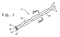
図1は、銅などの中心導体各8および10、並びにポリマー絶縁体各12および14からそれぞれなるポリマー絶縁導体4および6のツイストペア2を示す。ツイストペア2を形成するツイニングプロセスは従来の操作であり、絶縁体12および14の露出面が接触点16および18などで押し合わせられる。接触点16および18は、概ね、2つの絶縁導体間の正弦曲線接触を描く螺旋接触線又は接触面の部分である。ツイストペアの絶縁導体間のインピーダンスの均一性のために、接触線が連続していることが好ましい。絶縁体が全部発泡している場合、発泡絶縁体の圧潰を引き起こす力は、ツイニング操作に起因し、絶縁導体のツイストペア中に残存する。ポリマー絶縁体の耐圧潰性部分は発泡性部分を保護する。
FIG. 1 shows a
図2は、導体8および絶縁体12を含む絶縁導体4の断面を示し、耐圧潰性部分は5つの非発泡領域20に細分され、これらは5つの発泡領域22と交互になっている。領域20は、本質的に発泡していないことによってその耐圧潰性を得る。図示されている実施形態では、領域20は、発泡絶縁体領域22の厚さ全体を通って半径方向に延び、導体8に付着しており、それによって絶縁体の露出面24に加えられるツイニング力は導体8に支持され、領域20の耐圧潰性を増加させる。好ましくは、非発泡領域は、ポリマー絶縁体の外面から測定して、絶縁体の厚さの少なくとも40%、より好ましくは少なくとも60%を通って延びる。領域20が発泡領域22の厚さの中に半径方向に延びるため、たとえ領域20の下に発泡体構造があっても、これらの領域の内側に先細りになる断面によって、これ自体が耐圧潰性を付与する。この点に関して、領域20は台形に類似している。領域20のこの台形の形状(断面)の辺26および28は、接触する発泡体領域22によって支持される。それらの領域は、好ましくは中心導体8を中心にして対称である。好ましくは、これらの領域の対称分布は、互いに均一なサイズである発泡領域と、互いに均一なサイズである耐圧潰性領域を含み、発泡領域と耐圧潰性領域は絶縁体の断面に均一に分布している(均一な間隔で配置されている)。
FIG. 2 shows a cross-section of the insulated conductor 4 including the
図3では、耐圧潰性領域30と発泡領域32は、互いに交互になっており、導体31を中心にして対称である。この実施形態では、層34は、絶縁体の最内面に存在し、即ち、導体に接触しており、この層は本質的に発泡していない。この点に関して、この層の組成物は、発泡セル造核剤の存在を含む発泡領域32の組成物と同じであるが、押出プロセス条件は、導体に隣接する領域で発泡が起こったとしても非常に僅かであるようにする、即ち、層34が本質的に発泡しないようにする。このプロセス条件は、発泡領域32を形成する発泡性ポリマー組成物が導体と接触する時に、導体が比較的「低温」であるようにすることを含み、それによって、この導体隣接領域は、溶融ポリマー中に気泡(発泡セル)が形成できるより速く冷却され、その結果、この領域と発泡領域の間に発泡構造の差が生じる。得られる層34は、概ね、空孔率が約10%未満、好ましくは約5%未満であり、概ね空孔率が少なくとも約20%、好ましくは少なくとも30%である発泡領域とは幾らか視覚的に異なる。
In FIG. 3, the crushing
図3の実施形態では、耐圧潰性領域30は層34の中に延び、本質的に発泡していない層36もまたポリマー絶縁体の外(露出)面に存在する。層34および36は、領域30を相互接続し、ポリマー絶縁体全体の耐圧潰性を増加させる。層34の場合のように、層36も本質的に発泡していない。発泡性組成物の幾らかは、押出ポリマー形成層36のポリマーを貫通し、幾らか気泡を形成する可能性がある。本質的に発泡していない層36の状態は、層36とそれに隣接する発泡領域の間の境界面の不規則性に鑑みて、前述の層34と同様に特徴付けることができる。それにも関わらず、層34および/又は36が存在するとき、それらがそれぞれ、ポリマー絶縁体の全厚の少なくとも約10%を構成することが好ましい。
In the embodiment of FIG. 3, the
図4の実施形態は、耐圧潰性領域38が発泡領域40の中に延びるが、ポリマー絶縁体の外面から測定した時、ポリマー絶縁体の全厚の約60%にしか延びないということが、図3のものとは異なる。図3の実施形態のように、露出した表面層42は領域38を相互接続して存在するが、導体41の表面に隣接する領域は図3の層34よりはるかに多く発泡している。それにも関わらず、この実施形態は、依然として、図4に示すように耐圧潰性領域の間に交互にあり且つそれらの下に延びる発泡領域と同じ空孔率を有する発泡組成物で全部構成された絶縁体と比較して、顕著な耐圧潰性を示す。
The embodiment of FIG. 4 shows that the
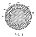
図5の実施形態では、発泡体/耐圧潰性部分(スプライン(spline))絶縁体構造の断面構造は、導体46を中心にして対称に配置され、それぞれ導体の表面と絶縁体の表面にある非発泡層48および49で相互接続された9つのスプライン44を備える。スプラインは発泡領域50と交互になっている。
In the embodiment of FIG. 5, the cross-sectional structure of the foam / crush-proof portion (spline) insulator structure is arranged symmetrically about the
図2〜5に示されているポリマー絶縁体の全ての実施形態で、ポリマー絶縁体の細分され、交互になっている領域、即ち、耐圧潰性領域と発泡領域を形成する構造は、導体の長さに沿って連続的に延びる。これらの領域はまた互いに補完し、ポリマー絶縁体の厚さ全体を構成し得る。図3および4の絶縁体構造の断面図は、耐圧潰性領域を、発泡領域の中に半径方向に全部延びることもあれば、部分的に延びることもある台形の形状のアーム(arms)として示すが、それらは、実際、絶縁導体の長さに沿って延びるスプラインであり、発泡領域は、このようなスプラインの間の空間、および、場合によってはこのようなスプラインの下の空間を占める。図1から、ツイストペアの絶縁導体は互いに交差し(crossover)、それによってスプラインがポリマー絶縁体の露出面間の接触部に存在するようになることが分かる。スプラインの幅および頻度は、外側の本質的に発泡していない層と共に、接触するポリマー絶縁体間に耐圧潰性境界面を提供する。絶縁体中に存在するポリマーの量を最小限にし、それによって静電容量が最小限になるように、発泡していないスプラインの幅は、好ましくは、所望の耐圧潰性と整合するように最小限にされる。絶縁体の断面中の非発泡領域の面積は、総断面積の約50%以下、より好ましくは約40%以下である。撚られた絶縁導体が互いに連続的に接触するため、幾つかの接触点はスプライン間ではなく、スプラインと外側非発泡層(例えば、図3の非発泡層36)又は発泡絶縁体(例えば、図2の発泡領域22)の間となる可能性があり、その場合、ツイストペアの直径の合計の損失は、耐圧潰性領域が存在しない場合の約半分になる。いずれにしても、これらがツイストペアのポリマー絶縁体間の接触点となる場合、隣接するスプライン間の接触は、各発泡絶縁体領域を支持する(各発泡絶縁体領域の圧潰を制限する)傾向がある。このような圧潰は、一方の絶縁導体がツイストペアの他方の絶縁導体の絶縁体中に存在する隣接するスプラインに接触するまでしか進行しない。スプラインの数および/又は幅を増加させることによって、スプライン間の接触の可能性を増加させることができる。従って、好ましくは、少なくとも5つの耐圧潰性領域、より好ましくは少なくとも7つの耐圧潰性領域、更により好ましくは少なくとも9つの耐圧潰性領域がポリマー絶縁体中に存在する。これらの耐圧潰性領域は、好ましくは断面積がほぼ等しく、好ましくは発泡領域と交互に対称になっている。これらの数のスプラインのそれぞれについて、絶縁体の厚さへのスプラインの貫入(半径方向の延び)は前述の通りであってもよい。同様に、本質的に発泡していないポリマーからなる表面層は、絶縁体内の導体に隣接する表面に、又は絶縁体の露出(外)面に、又はその両方の位置に配置されていてもよく、それらの厚さは前述の通りであってもよい。
In all embodiments of the polymer insulator shown in FIGS. 2-5, the structure that forms the subdivided and alternating regions of the polymer insulator, i.e., the crush-resistant region and the foamed region, is the same as that of the conductor. Extends continuously along the length. These regions can also complement each other and constitute the entire thickness of the polymer insulator. The cross-sectional views of the insulator structure of FIGS. 3 and 4 show the crush-resistant regions as trapezoidal arms that may extend entirely or partially in the foam region. Although shown, they are actually splines that extend along the length of the insulated conductor, and the foam region occupies the space between such splines and possibly the space under such splines. From FIG. 1, it can be seen that the insulated conductors of the twisted pair cross one another so that the splines are present at the contact between the exposed surfaces of the polymer insulator. The width and frequency of the spline, along with the outer, essentially unfoamed layer, provides a collapsible interface between contacting polymer insulators. The width of the unfoamed spline is preferably minimized to match the desired crush resistance so that the amount of polymer present in the insulator is minimized, thereby minimizing capacitance. Limited. The area of the non-foamed region in the cross section of the insulator is about 50% or less, more preferably about 40% or less of the total cross-sectional area. Because the twisted insulated conductors are in continuous contact with each other, some contact points are not between the splines, but the splines and the outer non-foamed layer (eg, the
図6は、図2、図3、および図5の絶縁体構造を得ることができる押出機クロスヘッド設計54の一実施形態の部分図を示す。クロスヘッド54の本体52内に同心状に嵌合しているのは、ダイ56とダイ先端58である。不活性ガスで加圧された(不活性ガスが注入された)溶融ポリマー組成物が、ポート64によって押出機(図示せず)からダイの中に供給され、クロスヘッド本体52には周囲チャネル57があり、ダイ先端58に関して、この溶融ポリマー組成物がダイ先端の周囲全体に流れ、ダイ56とダイ先端58の間の狭い環状の間隙59に流入し、流通することを可能にする。ダイ先端58は、軸方向のワイヤ(導体)ガイド60を有し、ダイ56とダイ先端58の間の環状オリフィス62は、押し出された溶融ポリマー組成物の管状の形状の寸法を画定するが、溶融ポリマー組成物は真空によってドローダウンされ、ワイヤガイド60を通して電線に付けられ、ポリマー絶縁体を形成する。溶融ポリマー絶縁体の発泡性部分の発泡は、ポリマー組成物が電線上にドローダウンされるまで遅延され、その時、発泡が起こり、このようにして絶縁された電線は冷却され、発泡体構造を凍結する。
FIG. 6 shows a partial view of one embodiment of an
クロスヘッドおよび押出プロセスの前述の記載は従来のものである。本発明の実施を可能にする構造および条件は後述する。ポリマー絶縁体の耐圧潰性領域は、サイド押出機(図示せず)からポート70を通して溶融ポリマーを注入することによって得られる。この溶融ポリマーは不活性ガスで加圧されなかったが、それによって、この溶融ポリマーは非発泡性である。クロスヘッド本体52とダイ56の間に環状チャネル72が形成され、溶融ポリマーがダイ56を包囲することを可能にする。チャネル72と環状の間隙59の間を連通する複数の追加のポート74がダイに設けられる。追加のポート74の数と半径方向の分布は、ポリマー絶縁体中に形成される耐圧潰性領域(スプライン)の数と半径方向の分布に対応する。これらの追加のポートを流通する溶融ポリマーは、ポリマー絶縁体の耐圧潰性領域を形成する。操作中、溶融した発泡性ポリマー組成物は、環状の間隙59に沿って流動し(移動し)、溶融ポリマーは追加のポート74を通って流動し(移動し)、溶融した発泡性ポリマー組成物の流れを貫通し、細分し得る。追加のポート74を流通する溶融ポリマーは発泡用ではない。環状の間隙59に供給される発泡性溶融ポリマー組成物の中に溶融ポリマーが追加のポート74から貫通配置されるが、これは、環状のオリフィス62を通って移動し、電線上にドローダウンして電線上に発泡耐圧潰性ポリマー絶縁体を形成する間、維持される。追加のポートから溶融ポリマーが貫通する程度は、それぞれポート70とポート64を通るポリマーとポリマー組成物の相対的流量によって制御される。耐圧潰性領域の台形の断面形状の形成は自然に起こる。導体の表面に層34(図3)などの本質的に発泡していない層を形成することは、発泡性ポリマー組成物が、環状オリフィス62からの押し出しに伴う溶融ポリマー組成物にかかる圧力の解放の結果として発泡できる前に、ダイ先端58を通る電線で発泡性ポリマー組成物が冷却されることによって達成される。この冷却を達成するために、電線は加熱されるが、比較的低温に、好ましくは約240°F(116℃)以下に加熱される。
The foregoing description of the crosshead and extrusion process is conventional. The structure and conditions enabling the implementation of the present invention will be described later. The crush area of the polymer insulator is obtained by injecting molten polymer through
図7のクロスヘッド76は、それが、ポリマー絶縁体の外面で耐圧潰性領域を相互接続する図5の本質的に発泡していない層49を作り出すように変更されていることを除いて、図6と同じ要素からなる。この点に関して、クロスヘッド本体は、ダイ56を取り囲む環状の間隙82を形成するように変更されており、環状のチャネル80は環状の開口部84を含む。この変更は、ポート70を流通する溶融ポリマーが追加のポート74と環状の間隙82の両方に流入すること可能にし、間隙82は、溶融ポリマーが追加のポート74の上流にある環状の間隙59に入ることを可能にする。この上流で入るものは、流動する溶融した発泡性ポリマー組成物を十分貫通して表面層を形成し、それはまた追加のポート74から流入する溶融ポリマーによって貫通され、耐圧潰性領域を形成する。図3の層36のような表面層の厚さは、ポート70を流通する溶融ポリマーとポート64を流通する溶融した発泡性ポリマー組成物の相対的流量によって制御される、即ち、所望の厚さの非発泡外側絶縁体層と所望の貫通度のスプラインのためのポリマーを供給するのに十分な溶融ポリマーがポート70を通して供給される。従って、図2に示すようにスプラインは導体に到達することができるか、又は内側非発泡層34(図3)又は48(図5)に到達することができる。図3および図5はそれぞれこれらの層34および48を、それらの各スプラインに対して一体であるものとして示し、実際、これらの内層と各スプラインの間の相互接続が層とスプラインの間の接触線又は溶接線であるとき、それにも関わらずスプラインをしっかりと支持する。好ましくは、耐圧潰性領域は、図2の導体8又はそれぞれ図3および図5の内側非発泡層34および48である中実の材料で少なくとも支持されるように、絶縁体の厚さを本質的に全部通って延びる。非発泡表面層はまた、米国特許第5,783,219号明細書に開示されているダイ設計を使用することによって得られてもよい。
The
本発明に使用されるフルオロポリマーは、好ましくは、テトラフルオロエチレン(TFE)とヘキサフルオロプロピレン(HFP)のコポリマーである。これらのコポリマー中、HFP含有量は典型的には約6〜17重量%、好ましくは9〜17重量%(HFPI×3.2から計算される)である。HFPI(HFPインデックス)は、U.S.Statutory Invention Registration H130に開示されているように、特定のIR波長における赤外線(IR)吸光度の比である。好ましくは、TFE/HFPコポリマーは、特性を改善するため、少量の追加のコモノマーを含む。好ましいTFE/HFPコポリマーは、TFE/HFP/パーフルオロ(アルキルビニルエーテル)(PAVE)であり、ここでアルキル基の炭素数は1〜4である。好ましいPAVEモノマーは、パーフルオロ(エチルビニルエーテル)(PEVE)およびパーフルオロ(プロピルビニルエーテル)(PPVE)である。追加のコモノマーを含有する好ましいTFE/HFPコポリマーは、HFP含有率約6〜17重量%、好ましくは9〜17重量%であり、PAVE含有率(好ましくはPEVE)約0.2〜3重量%であり、コポリマーの残部はTFEであり、コポリマーは合計100重量%になる。FEP組成物の例としては、米国特許第4,029,868号明細書(Carlson)、同第5,677,404号明細書(Blair)、および同第6,541,588号明細書(Kaulbachら)およびU.S.Statutory Invention Registration H130に開示されているものがある。FEPは部分的に結晶性である、即ち、エラストマーではない。部分的に結晶性とは、ポリマーが幾らかの結晶性を有し、ASTM D3418に従って測定される検出可能な融点と少なくとも約3J/gの融解吸熱を特徴とすることを意味する。 The fluoropolymer used in the present invention is preferably a copolymer of tetrafluoroethylene (TFE) and hexafluoropropylene (HFP). In these copolymers, the HFP content is typically about 6-17% by weight, preferably 9-17% by weight (calculated from HFPI × 3.2). HFPI (HFP index) is a U.S. S. The ratio of infrared (IR) absorbance at a particular IR wavelength, as disclosed in the Status Invention Registration H130. Preferably, the TFE / HFP copolymer contains a small amount of additional comonomer to improve properties. A preferred TFE / HFP copolymer is TFE / HFP / perfluoro (alkyl vinyl ether) (PAVE), wherein the alkyl group has 1 to 4 carbon atoms. Preferred PAVE monomers are perfluoro (ethyl vinyl ether) (PEVE) and perfluoro (propyl vinyl ether) (PPVE). Preferred TFE / HFP copolymers containing additional comonomers have an HFP content of about 6-17% by weight, preferably 9-17% by weight, and a PAVE content (preferably PEVE) of about 0.2-3% by weight. Yes, the remainder of the copolymer is TFE, for a total of 100% by weight of copolymer. Examples of FEP compositions include U.S. Pat. Nos. 4,029,868 (Carlson), 5,677,404 (Blair), and 6,541,588 (Kaulbach). Et al.) And U.I. S. Some are disclosed in the State Invention Registration H130. FEP is partially crystalline, i.e. not an elastomer. Partially crystalline means that the polymer has some crystallinity and is characterized by a detectable melting point measured according to ASTM D3418 and a melting endotherm of at least about 3 J / g.
溶融押出可能となるように溶融加工可能である、他のフルオロポリマー、即ち、少なくとも35重量%のフッ素を含有するポリマーを使用することができるが、高速押出可能でありコストが比較的低いため、FEPが好ましい。特定の用途では、エチレン/テトラフルオロエチレン(ETFE)ポリマーが好適であるが、パーフルオロポリマーが好ましく、これらには、テトラフルオロエチレン(TFE)と一般にPFAとして知られているパーフルオロ(アルキルビニルエーテル)(PAVE)のコポリマー、およびある特定の場合にはMFAが挙げられる。PAVEモノマーとしては、パーフルオロ(エチルビニルエーテル)(PEVE)、パーフルオロ(メチルビニルエーテル)(PMVE)、およびパーフルオロ(プロピルビニルエーテル)(PPVE)が挙げられる。TFE/PEVEおよびTFE/PPVEは、好ましいPFAである。MFAは、TFE/PPVE/PMVEコポリマーである。しかし、前述のように、FEPが最も好ましいポリマーである。 Other fluoropolymers that are melt processable to be melt extrudable, i.e., polymers containing at least 35 wt% fluorine, can be used, but are high speed extrudable and relatively low cost, FEP is preferred. For certain applications, ethylene / tetrafluoroethylene (ETFE) polymers are preferred, but perfluoropolymers are preferred, which include tetrafluoroethylene (TFE) and perfluoro (alkyl vinyl ether), commonly known as PFA. Copolymers of (PAVE), and in certain cases MFA. PAVE monomers include perfluoro (ethyl vinyl ether) (PEVE), perfluoro (methyl vinyl ether) (PMVE), and perfluoro (propyl vinyl ether) (PPVE). TFE / PEVE and TFE / PPVE are preferred PFAs. MFA is a TFE / PPVE / PMVE copolymer. However, as mentioned above, FEP is the most preferred polymer.
本発明に使用されるフルオロポリマーはまた溶融加工可能である、即ち、ポリマーは、押出などの溶融加工によって加工され、有用であるように十分な強度を有する電線絶縁体を製造できるほど、溶融状態で十分な流動性がある。本発明に使用されるパーフルオロポリマーのメルトフローレート(MFR)は、好ましくは約5g/10分〜約50g/10分の範囲、好ましくは少なくとも約20g/10分、より好ましくは少なくとも約25g/10分である。 The fluoropolymers used in the present invention are also melt processable, i.e., the polymer is processed by melt processing, such as extrusion, so that the melt state is sufficient to produce a wire insulation with sufficient strength to be useful. With sufficient fluidity. The melt flow rate (MFR) of the perfluoropolymer used in the present invention is preferably in the range of about 5 g / 10 min to about 50 g / 10 min, preferably at least about 20 g / 10 min, more preferably at least about 25 g / min. 10 minutes.
MFRは、典型的には、米国特許第7,122,609号明細書(Chapman)に開示されているように、重合中の開始剤供給を変化させることによって制御される。所与の重合条件のための重合媒体およびコポリマー組成物中での開始剤濃度が高いほど、分子量は低くなり、MFRは高くなる。MFRはまた連鎖移動剤(CTA)を使用することによって制御されてもよい。MFRは、ASTM D−1238に従って、溶融ポリマーに5kgの荷重を使用し、372℃の溶融温度で、ASTM D2116−91a(FEPに関して)、ASTM D3307−93(PFA)、およびASTM D3159−91a(ETFEに関して)に記載のように測定される。 MFR is typically controlled by varying the initiator feed during polymerization, as disclosed in US Pat. No. 7,122,609 (Chapman). The higher the initiator concentration in the polymerization medium and copolymer composition for a given polymerization condition, the lower the molecular weight and the higher the MFR. MFR may also be controlled by using chain transfer agents (CTA). MFR uses a 5 kg load on the molten polymer in accordance with ASTM D-1238 and at a melt temperature of 372 ° C, ASTM D2116-91a (with respect to FEP), ASTM D3307-93 (PFA), and ASTM D3159-91a (ETFE) )).
水系重合で製造されたフルオロポリマーは、重合した時、炭素原子106個当たり少なくとも約400個の末端基を含有する。これらの末端基のほとんどは、押出中に受けるような熱に曝されるとき、分解などの化学反応を受け、押し出されたポリマーを変色させるか、又は押し出されたポリマーに不均一な泡を充満させるか、又はその両方であるという意味で不安定である。これらの不安定な末端基の例としては、−COF、−CONH2、−COOH、−CF=CF2、および/又は、−CH2OHが挙げられ、重合媒体、開始剤、連鎖移動剤(使用する場合)、緩衝剤(使用する場合)の選択などの重合態様によって決定される。好ましくは、フルオロポリマーは、不安定な末端基を実質的に全て、安定な末端基で置換するように安定化される。安定化の好ましい方法は、フルオロポリマーを蒸気又はフッ素に曝すことであり、これらはパーフルオロポリマーに高温で適用可能である。フルオロポリマーを蒸気に曝すことは、米国特許第3,085,083号明細書(Schreyer)に開示されている。フルオロポリマーをフッ素に曝すことは、米国特許第4,742,122号明細書(Buckmasterら)および米国特許第4,743,658号明細書(Imbalzanoら)に開示されている。これらのプロセスを本発明に使用することができる。末端基の分析はこれらの特許に記載されている。安定な−CF3末端基(フッ素化の生成物)の存在は、フッ素処理後に存在する不安定な末端基がないことから推論され、これは、好ましい安定な末端基であり、−CF2H末端基で安定化された(蒸気処理の生成物)フルオロポリマーと比較して低い損失係数(dissipation factor)が得られる。好ましくは、不安定な末端基の総数は、炭素原子106個当たり、このような末端基約80個以下、好ましくは炭素原子106個当たり、このような末端基約40個以下、最も好ましくは炭素原子106個当たりこのような末端基約20個以下である。 Fluoropolymers made by aqueous polymerization contain at least about 400 end groups per 10 6 carbon atoms when polymerized. Most of these end groups undergo chemical reactions such as degradation when exposed to heat as received during extrusion, causing the extruded polymer to discolor or filling the extruded polymer with non-uniform foam. It is unstable in the sense that it is both or both. Examples of these unstable end groups include —COF, —CONH 2 , —COOH, —CF═CF 2 , and / or —CH 2 OH, and include polymerization media, initiators, chain transfer agents ( When used) and the polymerization mode such as selection of buffer (when used). Preferably, the fluoropolymer is stabilized to replace substantially all labile end groups with stable end groups. A preferred method of stabilization is to expose the fluoropolymer to vapor or fluorine, which can be applied to the perfluoropolymer at elevated temperatures. Exposure of fluoropolymers to vapor is disclosed in US Pat. No. 3,085,083 (Schreyer). Exposure of fluoropolymers to fluorine is disclosed in US Pat. No. 4,742,122 (Buckmaster et al.) And US Pat. No. 4,743,658 (Imbalzano et al.). These processes can be used in the present invention. End group analysis is described in these patents. The presence of a stable —CF 3 end group (product of fluorination) is inferred from the lack of unstable end groups present after fluorination, which is the preferred stable end group, and —CF 2 H Low loss factors are obtained compared to fluoropolymers stabilized with end groups (product of steam treatment). Preferably, the total number of unstable end groups per 10 6 carbon atoms, such end groups of about 80 or less, preferably per 10 6 carbon atoms, such end groups to about 40 or less, and most preferably Has no more than about 20 such end groups per 10 6 carbon atoms.
耐圧潰性領域および発泡領域に存在するフルオロポリマーは、好ましくは、絶縁導体のツイストペアの通常の使用中、これらの領域が分離不可能であるという意味で、相溶性があるほど十分類似しており、同一であってもよい。 The fluoropolymers present in the crush and foam regions are preferably sufficiently similar to be compatible in the sense that these regions are not separable during normal use of twisted pairs of insulated conductors. , May be the same.
また、ポリオレフィンを本発明による絶縁体として使用してもよい。ポリオレフィンの例としては、ポリプロピレン(例えば、アイソタクチックポリプロピレン)、高密度ポリエチレン(HDPE)、直鎖低密度ポリエチレン(LLDPE)(例えば、比重0.89〜0.92を有する)などの直鎖ポリエチレンが挙げられる。Dow Chemical CompanyのINSITE(登録商標)触媒技術によって製造された直鎖低密度ポリエチレン、およびExxon Chemical Companyから入手可能なEXACT(登録商標)ポリエチレンを本発明に使用することができる;これらの樹脂は(mLLDPE)と総称されている。これらの直鎖低密度ポリエチレンは、エチレンと少量のより高級なαモノオレフィン、例えば、炭素数4〜8のもの、典型的にはブテン又はオクテンとのコポリマーである。これらの熱可塑性ポリマーのいずれも、単一のポリマーであっても又はポリマーのブレンドであってもよい。従って、EXACT(登録商標)ポリエチレンは、分子量の異なるポリエチレンのブレンドであることが多い。 Polyolefins may also be used as insulators according to the present invention. Examples of polyolefins include linear polyethylene such as polypropylene (eg, isotactic polypropylene), high density polyethylene (HDPE), and linear low density polyethylene (LLDPE) (eg, having a specific gravity of 0.89 to 0.92). Is mentioned. Linear low density polyethylene produced by Dow Chemical Company's INSITE (R) catalyst technology and EXACT (R) polyethylene available from Exxon Chemical Company can be used in the present invention; mLLDPE). These linear low density polyethylenes are copolymers of ethylene and small amounts of higher alpha monoolefins, such as those having 4 to 8 carbon atoms, typically butene or octene. Any of these thermoplastic polymers may be a single polymer or a blend of polymers. Therefore, EXACT® polyethylene is often a blend of polyethylenes of different molecular weights.
存在する場合、図3の層34および36などの、外面および内面の本質的に発泡していない層を含むポリマー絶縁体の全厚は、一般に約4〜20ミル(100〜500μm)、好ましくは約6〜14ミル(150〜350μm)である。この厚さは、図5のオリフィス52などの環状のオリフィス、並びに、ドローダウン比および発泡領域の空孔率によって決定される(established)。ポリマー絶縁体の発泡領域を形成するポリマーを発泡させる任意の方法を使用することができる。しかし、低い反射減衰量(return loss)および高い信号伝送速度などの電気特性の最良の組み合わせが得られるように、使用する方法により、小さく且つ均一なセル(空孔)が得られることが好ましい。この点に関して、セルは好ましくは直径約50マイクロメートル以下であり、空孔率は約10〜70%、好ましくは約20〜50%、より好ましくは約20〜35%である。空孔率は、実施例の項目で記載するように、絶縁導体の静電容量測定により求められる。これは、絶縁体の発泡部分と非発泡部分の平均空孔率である。絶縁体の発泡領域でこの発泡体結果を得るのに好ましい方法は、ポート64(図5)を通して供給する押出機内の溶融ポリマーへの高圧不活性ガス注入の使用、および溶融ポリマーに発泡セル造核剤を含有させることであり、発泡セル造核剤は、押出ダイの下流で発泡が起こるとき、小さく均一なサイズのセルの形成を開始させる。高圧不活性ガス注入によって起こる発泡は、押し出されるポリマー組成物のチューブが発泡の開始前に導体にドローダウンされるのに十分長い時間、遅延される。
When present, the total thickness of the polymer insulator, including the outer and inner surface essentially non-foamed layers, such as
所望の耐圧潰性結果を得るため、非発泡耐圧潰性領域、並びに非発泡内層および外層の割合を変える時、溶融ポリマーに注入される不活性ガスの圧力を変えることによって発泡領域の空孔率を変え、ポリマー絶縁体の静電容量を一定不変にすることができる。従って、絶縁体中の非発泡ポリマーの割合を増加させる時、非発泡ポリマーの割合を増加させることによって絶縁体構造を変える前の発泡/非発泡絶縁体構造とほぼ同じ静電容量が得られるように、空孔率も増加させる。 In order to obtain the desired crushing result, the porosity of the foamed region can be changed by changing the pressure of the inert gas injected into the molten polymer when changing the proportion of the non-foamed crushable region and the non-foamed inner and outer layers. The capacitance of the polymer insulator can be made constant. Therefore, when increasing the proportion of the non-foamed polymer in the insulator, increasing the proportion of the non-foamed polymer can provide approximately the same capacitance as the foam / non-foamed insulator structure before changing the insulator structure. In addition, the porosity is also increased.
好ましくは、本発明に使用されるポリマーに添加される発泡セル造核剤は、押出機加工条件下で熱的に安定である。このような造核剤の例としては、米国特許第4,877,815号明細書(Buckmasterら)に開示されているもの、即ち、熱的に安定な有機酸、およびスルホン酸又はホスホン酸の塩、好ましくは窒化ホウ素と組み合わせたもの、並びに、米国特許第4,764,538号明細書に開示されている熱的に安定な無機塩が挙げられる。好ましい有機酸又は塩は、式F(CF2)nCH2CH2−スルホン又はホスホン酸又はその塩を有し、式中、nは6、8、10又は12又はこれらの混合である。 Preferably, the foam cell nucleating agent added to the polymer used in the present invention is thermally stable under extruder processing conditions. Examples of such nucleating agents are those disclosed in US Pat. No. 4,877,815 (Buckmaster et al.), Ie, thermally stable organic acids, and sulfonic or phosphonic acids. Salts, preferably in combination with boron nitride, as well as thermally stable inorganic salts disclosed in US Pat. No. 4,764,538. Preferred organic acids or salts have the formula F (CF 2 ) n CH 2 CH 2 -sulfone or phosphonic acid or a salt thereof, where n is 6, 8, 10 or 12 or a mixture thereof.
図5の層48などの本質的に発泡していない層は、発泡領域と同じ組成物からなるが、導体と接触する冷却効果により発泡を回避する。耐圧潰性領域44などのスプライン、および図5の外層49は、両方とも本質的に発泡していないが、その理由は異なる。これらの領域を形成するポリマーは、高圧不活性ガス注入の下流で絶縁体の発泡性領域を形成する溶融ポリマーに注入され、それによって、この発泡の原因は、ポート70を流通するポリマーには存在しない。本質的に発泡していない領域のいずれかに少数の発泡セルが形成されてもよいが、これらの領域に発泡性組成物が貫入することのみによる。更に、発泡領域と非発泡領域の間の境界線は、発泡量域内の空孔(セル)を観察するのに必要な微視的スケールで、さほど鮮明でなくてもよい、即ち、幾分不規則であってもよい。
An essentially non-foamed layer, such as
絶縁体を形成する耐圧潰性領域と発泡領域は、絶縁体を形成する押出発泡プロセスの結果として絶縁導体の長さに沿って延びるが、これらの領域の長手方向の配置はまた、ピッチの長い(long−lay)螺旋の形態である、即ち、これらの領域を形成する溶融ポリマーに押出機スクリュによって加えられる回転運動によって、ピッチの長い螺旋が形成され、螺旋の1回転は絶縁導体の長さ少なくとも1メートル毎に起こり得る。押出発泡プロセスの別の属性は、導体を被覆した後、発泡中に発泡領域の直径が増加するにつれ、非発泡領域の直径も対応して拡大することである。意外にも、とりわけ耐圧潰性領域(スプライン)が絶縁体の厚さを通って延びるとき、発泡領域の発泡膨張の力により、スプラインもそれに対応して半径方向に延び、そのため、ポリマー絶縁体は実質的に均一な直径を有する、即ち、断面が実質的に円形のままである。外層がスプラインを相互接続して存在する場合、この外層は、ポリマー絶縁体の表面が冷却されているということにもかかわらず、ポリマー押出物が導体に最初に接触するときよりも大きい発泡後のポリマー絶縁体の直径に適応するように伸長する。 The crush-resistant regions and foamed regions that form the insulators extend along the length of the insulated conductor as a result of the extrusion foaming process that forms the insulators, but the longitudinal arrangement of these regions is also long pitch (Long-lay) in the form of a helix, i.e., the rotational motion applied by the extruder screw to the molten polymer forming these regions forms a long pitch helix, one revolution of the helix being the length of the insulated conductor It can happen at least every 1 meter. Another attribute of the extrusion foaming process is that after coating the conductor, as the diameter of the foamed area increases during foaming, the diameter of the non-foamed area correspondingly increases. Surprisingly, especially when the crushing region (spline) extends through the thickness of the insulator, the foam expansion force of the foaming region causes the spline to extend correspondingly in the radial direction, so that the polymer insulator It has a substantially uniform diameter, i.e. the cross-section remains substantially circular. When an outer layer is present interconnecting the splines, this outer layer is larger after foaming than when the polymer extrudate first contacts the conductor, despite the fact that the surface of the polymer insulator is cooled. Stretch to accommodate the diameter of the polymer insulator.
本発明のポリマー絶縁導体のツイストペアを、既存のツイストペアと同様に使用することができる、即ち、他のツイストペアと、好ましくはまた本発明のツイストペアと組み合わせて、所望の通信ケーブルを製造することができる。特に、本発明のツイストペアは、中実のポリマー絶縁体より細い(直径が小さい)ポリマー絶縁電線を提供し、本発明のツイストペアが、10GB/sの信号周波数での伝送のような高性能に必要なケーブルを小型化することを可能にする。この小型化は、設備コネクタおよび搬送波を変更することなく高性能を満たすことを可能にする。 The twisted pair of polymer insulated conductors of the present invention can be used in the same manner as existing twisted pairs, i.e., in combination with other twisted pairs, preferably also with the twisted pairs of the present invention, to produce the desired communication cable. . In particular, the twisted pair of the present invention provides a polymer insulated wire that is thinner (smaller in diameter) than a solid polymer insulator, and the twisted pair of the present invention is required for high performance such as transmission at a signal frequency of 10 GB / s. This makes it possible to reduce the size of cables. This miniaturization makes it possible to meet high performance without changing the equipment connector and carrier wave.
ポリマー絶縁導体の耐圧潰性は、5mm四方の対向するプラテン間で5mm/分の速度で絶縁導体の長さを圧潰することを含むUL−444の手順によって決定され、各プラテンは、試験される絶縁導体の導体に電気的に接続されている。導体とプラテンの1つ又は両方の間に電気回路が形成されることによって示される絶縁の失敗は、短絡の前のピーク荷重又は単にピーク荷重である。好ましくは、本発明の1つの絶縁導体、好ましくはツイストペアの両方の絶縁導体によって提供されるピーク荷重は、絶縁体が発泡体であり、耐圧潰性領域を有していない対応する絶縁導体のピーク荷重より少なくとも約10%大きく、好ましくは少なくとも約20%大きい。非発泡フルオロポリマーの外面層(例えば、約1ミル(25μm)までの厚さを有する)が存在する場合、これは耐圧潰性領域と見なされない。対応する絶縁導体とは、寸法(絶縁体の厚さおよび導体の直径)および静電容量が同じであり、フルオロポリマーが同じであることを意味する。耐圧潰性の別の尺度は、ツイニング操作で起こるような絶縁体の初期変形に対する耐性である。この耐圧潰性は、荷重の増加に伴う移動(ポリマー絶縁体の全径の減少)の曲線を記録すること、および、1〜4ミル(25〜100μm)移動(変形)した領域のこの曲線の傾きを求めることによって決定される。この移動量は、比較例および実施例で使用される絶縁体厚さ(10ミル(250μm))を基準にして、ポリマー絶縁体が元の厚さの80%に圧潰することに対応する。曲線の傾きは、ポリマー絶縁体の圧潰弾性率である。好ましくは、絶縁導体、好ましくはツイストペアの各絶縁導体の圧潰弾性率は、対応する絶縁導体の圧潰弾性率より、少なくとも約10%大きく、より好ましくは少なくとも約20%大きい。絶縁導体のピーク荷重および圧潰弾性率特性は、3つの測定値の平均値として求められる。プラテンに対して絶縁体の向きを定める手間はない。とりわけ圧潰弾性率測定値は、3つの測定で僅かしか変化しないことが分かった。 The crush resistance of a polymer insulated conductor is determined by the UL-444 procedure, which involves crushing the length of the insulated conductor at a rate of 5 mm / min between 5 mm square opposing platens, each platen being tested It is electrically connected to the conductor of the insulated conductor. The insulation failure indicated by the formation of an electrical circuit between one or both of the conductor and the platen is the peak load before the short circuit or simply the peak load. Preferably, the peak load provided by one insulated conductor of the present invention, preferably both insulated conductors of a twisted pair, is the peak of the corresponding insulated conductor where the insulator is a foam and does not have a crushed area. At least about 10% greater than the load, preferably at least about 20% greater. If an outer surface layer of non-foamed fluoropolymer (eg, having a thickness up to about 1 mil (25 μm)) is present, this is not considered a crush-resistant region. Corresponding insulated conductor means that the dimensions (insulator thickness and conductor diameter) and capacitance are the same and the fluoropolymer is the same. Another measure of crush resistance is the resistance to initial deformation of the insulator, such as occurs in a twisting operation. This crush resistance records the curve of the movement (decrease in the total diameter of the polymer insulator) with increasing load, and the curve of this curve in the area moved (deformed) by 1 to 4 mils (25 to 100 μm). It is determined by determining the slope. This amount of movement corresponds to the collapse of the polymer insulator to 80% of its original thickness, based on the insulator thickness (10 mil (250 μm)) used in the comparative examples and examples. The slope of the curve is the crush modulus of the polymer insulator. Preferably, the crush modulus of each insulated conductor, preferably each insulated conductor of the twisted pair, is at least about 10% greater, more preferably at least about 20% greater than the crush modulus of the corresponding insulated conductor. The peak load and the crush modulus property of the insulated conductor are obtained as an average value of three measured values. There is no effort to determine the orientation of the insulator relative to the platen. In particular, it was found that the crush modulus measurement value changed only slightly between the three measurements.
ポリマー絶縁電線の静電容量は、一般に、電線絶縁体押出ラインで測定される。この測定から、空孔率が次の関係から求められる:
静電容量=7.354K/log10(D/d)
式中、Kはポリマー絶縁体の誘電率であり、Dはポリマー絶縁導体の直径であり、dは導体の直径である。この式に静電容量の測定値(単位、pF/ft)を入れると、Kの値が求められる。Kは表1に示されている空孔率と関係がある。
The capacitance of a polymer insulated wire is generally measured with a wire insulator extrusion line. From this measurement, the porosity is determined from the following relationship:
Capacitance = 7.354 K / log 10 (D / d)
Where K is the dielectric constant of the polymer insulator, D is the diameter of the polymer insulated conductor, and d is the diameter of the conductor. If the measured value of capacitance (unit, pF / ft) is entered in this equation, the value of K can be obtained. K is related to the porosity shown in Table 1.

静電容量の式の誘電率(K)の計算から、上記に列挙した空孔率の補間法により、絶縁体の全体としての平均空孔率を求めることができる。絶縁体の発泡領域の断面積を絶縁体の全面積のパーセンテージとして測定し、絶縁体の全体としての空孔率をこのパーセンテージで割ることにより、絶縁体の発泡領域の実際の空孔率を求める。この表は、一般にパーフルオロポリマーに適用可能である。他のフルオロポリマーおよびポリオレフィンでは、誘電率と空孔率との関係を実験的に求めることができる。 From the calculation of the dielectric constant (K) in the capacitance equation, the average porosity of the insulator as a whole can be determined by the porosity interpolation methods listed above. Determine the actual porosity of the foamed area of the insulator by measuring the cross-sectional area of the foamed area of the insulator as a percentage of the total area of the insulator and dividing the overall porosity of the insulator by this percentage . This table is generally applicable to perfluoropolymers. For other fluoropolymers and polyolefins, the relationship between dielectric constant and porosity can be determined experimentally.
これらの実施例に使用されるフルオロポリマーは、10〜11重量%のHFPおよび1〜1.5重量%のPEVEを含有し、残部がTFEである市販の(DuPont製)フルオロポリマーである。このFEPは、MFR30g/10分であり、フッ素濃度を米国特許第6,838,545号明細書の実施例の2500ppmから1200ppmに減少させることを除いて、米国特許第6,838,545号明細書(Chapman)の実施例2の押出機フッ素化手順を使用してフッ素に曝すことにより安定化されたものである。発泡セル造核剤は、米国特許第4,877,815号明細書(Buckmasterら)に開示されているように、窒化ホウ素91.1重量%、四ホウ酸カルシウム2.5重量%、およびテロマーBスルホン酸のバリウム塩6.4重量%の混合物であり、これらの成分の組み合わせは合計100%である。発泡性フルオロポリマー組成物を形成するために、フルオロポリマーを発泡セル造核剤とドライブレンドし、フルオロポリマーと発泡セル造核剤の合計重量を基準にして0.4重量%の発泡セル造核剤濃度にした後、得られた混合物を押出機内でコンパウンドし、ペレットとして押し出し、次いでそれを押出ワイヤコーティング/発泡プロセスに使用する。ポリマー絶縁体の非発泡領域を形成するのに使用されるフルオロポリマーはそれ自体同じフルオロポリマーである。 The fluoropolymer used in these examples is a commercially available (DuPont) fluoropolymer containing 10-11 wt.% HFP and 1-1.5 wt.% PEVE with the balance being TFE. This FEP is MFR 30 g / 10 min, and the U.S. Pat. No. 6,838,545 is used except that the fluorine concentration is reduced from 2500 ppm to 1200 ppm in the examples of US Pat. No. 6,838,545. Stabilized by exposure to fluorine using the extruder fluorination procedure of Example 2 of Chapman. Foamed cell nucleating agents include 91.1% by weight boron nitride, 2.5% by weight calcium tetraborate, and telomer as disclosed in US Pat. No. 4,877,815 (Buckmaster et al.). It is a mixture of 6.4% by weight of barium salt of B sulfonic acid, and the combination of these components is 100% in total. To form a foamable fluoropolymer composition, the fluoropolymer is dry blended with a foam cell nucleating agent and 0.4% by weight foam cell nucleation based on the total weight of the fluoropolymer and the foam cell nucleating agent. After reaching the agent concentration, the resulting mixture is compounded in an extruder and extruded as pellets, which are then used in an extruded wire coating / foaming process. The fluoropolymer used to form the non-foamed region of the polymer insulator is itself the same fluoropolymer.
比較例
この実施例では、厚さ10ミル(250μm)の発泡フルオロポリマー絶縁体は、直径0.0226in(575μm)の銅線上に押出成形される。この絶縁体は48pF/ft(157pf/m)の静電容量を示し、これは空孔率約24%に対応する。同じ寸法の中実のフルオロポリマー絶縁体では、静電容量は54pF/ft(177pF/m)になる。空孔のセルサイズは均一であり、顕微鏡下に絶縁体の薄い断面を配置し、無作為に選択された20〜30個のセルの直径を測定し、結果を平均することによって求められる直径が50μm未満である。平均(mean)は平均セル直径であり、セル直径の変動係数(標準偏差を平均で割ったもの)が約50%未満、好ましくは約25%未満、より好ましくは約15%未満である場合、セルサイズは均一であると称される。絶縁体の発泡領域に加えて、絶縁体はまた、図3の層34および36に類似の内側および外側非発泡層も含むがスプラインはない。これらの層はそれぞれ、厚さ約1ミル(25μm)である。
Comparative Example In this example, a 10 mil (250 μm) thick foamed fluoropolymer insulator is extruded onto a 0.0226 in (575 μm) diameter copper wire. This insulator exhibits a capacitance of 48 pF / ft (157 pf / m), which corresponds to a porosity of about 24%. A solid fluoropolymer insulator of the same dimensions would have a capacitance of 54 pF / ft (177 pF / m). The cell size of the pores is uniform, a thin section of insulator is placed under the microscope, the diameter of 20-30 cells selected at random is measured, and the result is averaged. It is less than 50 μm. The mean is the average cell diameter and if the coefficient of variation in cell diameter (standard deviation divided by average) is less than about 50%, preferably less than about 25%, more preferably less than about 15%, The cell size is referred to as uniform. In addition to the foam region of the insulator, the insulator also includes inner and outer non-foamed layers similar to
このポリマー絶縁電線を製造する押出条件は、次の通りである:45mmの穴と30:1のL/D比を有する押出機を使用する。窒素を押出機内の溶融フルオロポリマー組成物に2800psig(19MPa)の圧力で注入する。押出環状オリフィスは、0.110in(2.8mm)のダイ先端外径と0.180in(4.6mm)のダイ内径によって画定される。ダイはまた、絶縁体の外層を作り出すため、幅0.011in(0.28mm)の環状の間隙(図7の58)を有するように変更されている。発泡セル造核剤を含有するフルオロポリマーの溶融温度は680°F(360℃)であり、銅線は230°F(110℃)に加熱され、これは非発泡内層を形成するのに十分溶融フルオロポリマー組成物を冷却する。ドローダウン比(DDR)は約20であり、ライン速度は740ft/分(226m/分)である。 The extrusion conditions for producing this polymer insulated wire are as follows: Use an extruder with 45 mm holes and an L / D ratio of 30: 1. Nitrogen is injected into the molten fluoropolymer composition in the extruder at a pressure of 2800 psig (19 MPa). The extruded annular orifice is defined by a die tip outer diameter of 0.110 in (2.8 mm) and a die inner diameter of 0.180 in (4.6 mm). The die has also been modified to have an annular gap (58 in FIG. 7) that is 0.011 in (0.28 mm) wide to create an outer layer of insulator. The melting temperature of the fluoropolymer containing the foam cell nucleating agent is 680 ° F. (360 ° C.) and the copper wire is heated to 230 ° F. (110 ° C.), which melts sufficiently to form a non-foamed inner layer. Cool the fluoropolymer composition. The drawdown ratio (DDR) is about 20 and the line speed is 740 ft / min (226 m / min).
得られる発泡フルオロポリマー絶縁体の圧潰弾性率は、13.9lbf/in(2.43N/mm)である。 The resulting foamed fluoropolymer insulator has a crush modulus of 13.9 lbf / in (2.43 N / mm).
実施例1
この実施例のフルオロポリマー絶縁体は、図3のものに類似しており、比較例の発泡絶縁体のものより空孔率が大きいこと、即ち、発泡領域のセル数が多いことに対応して、約48pF/ftの静電容量を示し、セルサイズは均一であり、比較例の発泡絶縁体中のセルとほぼ同じサイズである。この実施例のフルオロポリマー絶縁体の平均空孔率は、同一の静電容量によって示されるように、比較例のものと同じである。この絶縁体の圧潰弾性率は15.7lbf/in(2.75N/mm)である。
Example 1
The fluoropolymer insulator of this example is similar to that of FIG. 3, corresponding to a higher porosity than that of the foam insulator of the comparative example, ie, a larger number of cells in the foam region. , Exhibit a capacitance of about 48 pF / ft, have a uniform cell size, and are approximately the same size as the cells in the foam insulation of the comparative example. The average porosity of the fluoropolymer insulator of this example is the same as that of the comparative example, as indicated by the same capacitance. The crush modulus of this insulator is 15.7 lbf / in (2.75 N / mm).
このフルオロポリマー絶縁体は、5つの対称的に配置されたスプラインを提供するために、それぞれが環状の間隙59(図7)への開口部に狭窄部を有する5つのポート(図7の74)をダイ先端が含むことを除いて、前記に開示された押出機条件を使用して製造される。この狭窄部の直径は0.050in(1.27mm)である。窒素圧力は3100psig(21.4MPa)である。5つのポートを通して供給され、スプラインと外側非発泡層を形成するフルオロポリマーは、フルオロポリマーを690°F(366℃)の溶融温度に加熱するサイド押出機から得られる。サイド押出機は、38mmの穴と24:1のL/D比を有する。主押出機を通る溶融ポリマーの流量は、約20lb/時間(9.1kg/時間)であり、サイド押出機を通る溶融ポリマーの流量は、約10lb/時間(4.5kg/時間)である。ライン速度は712ft/分(217m/分)である。 This fluoropolymer insulator has five ports (74 in FIG. 7) each having a constriction at the opening to the annular gap 59 (FIG. 7) to provide five symmetrically arranged splines. Is manufactured using the extruder conditions disclosed above. The diameter of this constriction is 0.050 in (1.27 mm). The nitrogen pressure is 3100 psig (21.4 MPa). The fluoropolymer fed through five ports and forming the spline and outer non-foamed layer is obtained from a side extruder that heats the fluoropolymer to a melt temperature of 690 ° F. (366 ° C.). The side extruder has a 38 mm hole and an L / D ratio of 24: 1. The flow rate of molten polymer through the main extruder is about 20 lb / hour (9.1 kg / hour) and the flow rate of molten polymer through the side extruder is about 10 lb / hour (4.5 kg / hour). The line speed is 712 ft / min (217 m / min).
実施例2
この実施例のフルオロポリマー絶縁体は、導体の周囲に均一な間隔で配置され、絶縁体内で導体から半径方向に延びる12の非発泡領域を有すること以外、図2のものに類似している。この絶縁体の平均空孔率は20%である。これらのポリマー絶縁導体1組を対にし、ツイストペア(ツイストペア1)のインピーダンスを測定する。
Example 2
The fluoropolymer insulator of this example is similar to that of FIG. 2 except that it has twelve non-foamed regions that are evenly spaced around the conductor and extend radially from the conductor within the insulator. The average porosity of this insulator is 20%. A pair of these polymer insulated conductors is paired, and the impedance of the twisted pair (twisted pair 1) is measured.
全部発泡している、即ち、非発泡領域が存在しない別の発泡フルオロポリマー絶縁導体を調製するが、この絶縁体は同じ厚さと20%の空孔率を有する。これらの発泡フルオロポリマー絶縁導体1組を同じ条件で対にし、ツイストペア(ツイストペア2)のインピーダンスを測定する。 Another foamed fluoropolymer insulated conductor is prepared that is fully foamed, i.e., has no non-foamed areas, but this insulator has the same thickness and 20% porosity. A pair of these foamed fluoropolymer insulated conductors is paired under the same conditions, and the impedance of the twisted pair (twisted pair 2) is measured.
ツイストペア1のインピーダンスは、ツイストペア2のインピーダンスより1.5オーム大きく、発泡ポリマー絶縁体内の非発泡領域によって耐圧潰性が付与されることが分かる。ツイストペア1の絶縁体の発泡領域の空孔率は、ツイストペア2の絶縁体の空孔率より大きく、ツイストペア1の絶縁体中に存在する非発泡領域を補償する。
本発明は以下の実施の態様を含むものである。
1.ポリマー絶縁導体のツイストペアであって、前記ツイストペアを形成するための撚りによって、前記ポリマー絶縁導体の各ポリマー絶縁導体のポリマー絶縁体の表面が互いに接触し、各前記ポリマー絶縁導体のポリマー絶縁体が、
(i)前記ポリマー絶縁導体の前記ポリマー絶縁体の前記表面を互いに接触させることによって圧潰し得る発泡ポリマー部分、および
(ii)前記絶縁体内で前記発泡ポリマー部分の中に半径方向に延び、前記ポリマー絶縁導体の前記表面が互いに接触しているところに存在し、それによって、前記ポリマー絶縁導体の前記ポリマー絶縁体の前記表面を互いに接触させることによって起こる圧潰から前記発泡ポリマー部分を保護する耐圧潰性ポリマー部分、
を含む、ポリマー絶縁導体のツイストペア。
2.前記耐圧潰性部分が本質的に発泡していないポリマーである、前記1に記載のポリマー絶縁導体のツイストペア。
3.前記耐圧潰性ポリマー部分が前記発泡部分の厚さの少なくとも60%を通って延びる、前期1に記載のポリマー絶縁導体のツイストペア。
4.前記耐圧潰性ポリマー部分が、前記発泡ポリマー部分の中に半径方向に延びる、内側に先細りになる断面を有する、前記1に記載のポリマー絶縁導体のツイストペア。
5.ポリマー絶縁体が厚さ約4〜20ミルである、前記1に記載のポリマー絶縁導体のツイストペア。
6.前記ポリマー絶縁体の平均空孔率が約10〜70%である、前記1に記載のポリマー絶縁導体のツイストペア。
7.前記耐圧潰性ポリマー部分は、前記ツイストペアの幅が前記撚りの前の各前記ポリマー絶縁導体の直径の合計の少なくとも約90%となるような耐圧潰性を有する、前記1に記載のポリマー絶縁導体のツイストペア。
8.前記部分(i)および(ii)が前記ポリマー絶縁体全体を構成する、前記1に記載のポリマー絶縁導体のツイストペア。
9.前記部分(i)および(ii)がそれぞれ少なくとも3つの領域に細分されており、それらが互いに交互になっており、各前記ポリマー絶縁導体の長さに沿って延びる、前記1に記載のポリマー絶縁導体のツイストペア。
10.前記部分(ii)が、前記部分(ii)の前記少なくとも3つの領域を、各前記ポリマー絶縁導体の前記ポリマー絶縁体の前記表面で相互接続する、本質的に発泡していないポリマーの層を含む、前記9に記載のポリマー絶縁導体のツイストペア。
11.前記部分(ii)が、部分(ii)の前記少なくとも3つの領域を前記導体の前記表面で相互接続する、本質的に発泡していないポリマーの層を含む、前記9に記載のポリマー絶縁導体のツイストペア。
12.前記ポリマー絶縁体の前記ポリマーが、フルオロポリマーとポリオレフィンからなる群から選択される、前記9に記載のポリマー絶縁導体のツイストペア。
13.前記部分(i)および(ii)が、少なくとも5つの領域に細分されている、前記9に記載の絶縁導体のツイストペア。
14.前記部分(ii)が、前記絶縁体の厚さ全体を本質的に通って延びる、前記9に記載の絶縁導体のツイストペア。
The impedance of the twisted pair 1 is 1.5 ohms larger than the impedance of the
The present invention includes the following embodiments.
1. A twisted pair of polymer insulated conductors, wherein the surface of the polymer insulator of each polymer insulated conductor of the polymer insulated conductor is in contact with each other by twisting to form the twisted pair, and the polymer insulator of each polymer insulated conductor is
(I) a foamed polymer portion that can be crushed by bringing the surfaces of the polymer insulator of the polymer insulated conductor into contact with each other; and
(Ii) radially extending into the foamed polymer portion within the insulator and wherein the surfaces of the polymer insulated conductors are in contact with each other, thereby allowing the polymer insulator of the polymer insulated conductor to A collapsible polymer portion that protects the foamed polymer portion from crushing caused by bringing the surfaces into contact with each other;
A twisted pair of polymer insulated conductors, including
2. 2. The twisted pair of polymer insulated conductors according to 1 above, wherein the crushing portion is a polymer that is essentially not foamed.
3. The twisted pair of polymer insulated conductors of claim 1, wherein the collapsible polymer portion extends through at least 60% of the thickness of the foamed portion.
4). 2. The twisted pair of polymer insulated conductors according to 1, wherein the collapsible polymer portion has a radially inwardly tapered cross section extending radially into the foamed polymer portion.
5. The twisted pair of polymer insulated conductors of claim 1, wherein the polymer insulator is about 4-20 mils thick.
6). 2. The twisted pair of polymer insulated conductors according to 1 above, wherein an average porosity of the polymer insulator is about 10 to 70%.
7). 2. The polymer insulated conductor according to 1, wherein the crushable polymer portion has a crushing property such that a width of the twisted pair is at least about 90% of a total diameter of the polymer insulated conductors before twisting. Twisted pair.
8). The twisted pair of polymer insulated conductors according to 1 above, wherein the portions (i) and (ii) constitute the entire polymer insulator.
9. The polymer insulation of claim 1, wherein the portions (i) and (ii) are each subdivided into at least three regions, which alternate with each other and extend along the length of each polymer insulated conductor A twisted pair of conductors.
10. The portion (ii) includes an essentially unfoamed polymer layer interconnecting the at least three regions of the portion (ii) with the surface of the polymer insulator of each polymer insulated conductor. 10. A twisted pair of polymer insulated conductors according to 9 above.
11. 10. The polymer insulated conductor of claim 9, wherein said portion (ii) comprises a layer of essentially unfoamed polymer that interconnects said at least three regions of portion (ii) with said surface of said conductor. Twisted pair.
12 10. The twisted pair of polymer insulated conductors according to 9, wherein the polymer of the polymer insulator is selected from the group consisting of a fluoropolymer and a polyolefin.
13. The twisted pair of insulated conductors according to 9, wherein the portions (i) and (ii) are subdivided into at least five regions.
14 The twisted pair of insulated conductors of claim 9, wherein the portion (ii) extends essentially through the entire thickness of the insulator.
Claims (2)
前記ツイストペアを形成するための撚りによって、前記ポリマー絶縁導体の各ポリマー絶縁導体のポリマー絶縁体の表面が互いに接触し、
各前記ポリマー絶縁導体のポリマー絶縁体が、
(i)前記ポリマー絶縁導体の前記ポリマー絶縁体の前記表面を互いに接触させることによって圧潰し得る発泡ポリマー部分、および
(ii)前記絶縁体内で、前記絶縁体の表面から前記導体まで半径方向に全部または部分的に延び、前記ポリマー絶縁導体の前記表面が互いに接触しているところに存在し、それによって、前記ポリマー絶縁導体の前記ポリマー絶縁体の前記表面を互いに接触させることによって起こる圧潰から前記発泡ポリマー部分を保護する耐圧潰性ポリマー部分、
を含み、
前記部分(i)および(ii)がそれぞれ少なくとも3つの領域に細分されており、それらが互いに交互になっており、各前記ポリマー絶縁導体の長さに沿って延びる、
ポリマー絶縁導体のツイストペア。 A twisted pair of polymer insulated conductors in which the conductor is coated with a polymer insulator,
By twisting to form the twisted pair, the surface of the polymer insulator of each polymer insulated conductor of the polymer insulated conductor is in contact with each other,
A polymer insulator for each of the polymer insulated conductors,
(I) a foamed polymer portion that can be crushed by bringing the surfaces of the polymer insulator of the polymer insulated conductor into contact with each other; and (ii) all of the insulator in the radial direction from the surface of the insulator to the conductor. Or from the crushing caused by bringing the surfaces of the polymer insulator of the polymer insulated conductor into contact with each other, partly extending and existing where the surfaces of the polymer insulated conductor are in contact with each other Crush-resistant polymer part that protects the polymer part,
Only including,
Said portions (i) and (ii) are each subdivided into at least three regions, which alternate with each other and extend along the length of each said polymer insulated conductor;
A twisted pair of polymer insulated conductors.
Applications Claiming Priority (3)
| Application Number | Priority Date | Filing Date | Title |
|---|---|---|---|
| US92636107P | 2007-04-25 | 2007-04-25 | |
| US60/926,361 | 2007-04-25 | ||
| PCT/US2008/005012 WO2008133846A1 (en) | 2007-04-25 | 2008-04-18 | Crush resistant twisted pair communications cable |
Publications (3)
| Publication Number | Publication Date |
|---|---|
| JP2010525545A JP2010525545A (en) | 2010-07-22 |
| JP2010525545A5 JP2010525545A5 (en) | 2011-05-12 |
| JP5371958B2 true JP5371958B2 (en) | 2013-12-18 |
Family
ID=39689072
Family Applications (1)
| Application Number | Title | Priority Date | Filing Date |
|---|---|---|---|
| JP2010506220A Expired - Fee Related JP5371958B2 (en) | 2007-04-25 | 2008-04-18 | Crush-proof twisted pair communication cable |
Country Status (5)
| Country | Link |
|---|---|
| US (1) | US7473848B2 (en) |
| EP (1) | EP2140462A1 (en) |
| JP (1) | JP5371958B2 (en) |
| CN (1) | CN101663713B (en) |
| WO (1) | WO2008133846A1 (en) |
Cited By (1)
| Publication number | Priority date | Publication date | Assignee | Title |
|---|---|---|---|---|
| TWI734099B (en) * | 2018-04-25 | 2021-07-21 | 日商大金工業股份有限公司 | Stranded wire and its manufacturing method |
Families Citing this family (19)
| Publication number | Priority date | Publication date | Assignee | Title |
|---|---|---|---|---|
| US20090119901A1 (en) * | 2007-11-13 | 2009-05-14 | Commscope, Inc. Of North Carolina | Foam skin insulation with support members |
| US20090233052A1 (en) * | 2008-03-17 | 2009-09-17 | E.I. Du Pont De Nemours And Company | Conductors Having Polymer Insulation On Irregular Surface |
| JP5464080B2 (en) * | 2009-09-24 | 2014-04-09 | 住友電気工業株式会社 | Coaxial cable and multi-core coaxial cable |
| US9293241B2 (en) * | 2009-10-08 | 2016-03-22 | General Cable Technologies Corporation | Communication cable |
| US20110114362A1 (en) * | 2009-11-18 | 2011-05-19 | General Cable Technologies Corporation | Dual foamed-solid wire insulation with minimal solid |
| US9396846B2 (en) * | 2009-11-18 | 2016-07-19 | General Cable Technologies Corporation | Method of post-twinning dual solid foamed insulation |
| US8889990B2 (en) * | 2009-11-18 | 2014-11-18 | General Cable Technologies Corporation | Varied wire insulation using both foamed and unfoamed sections |
| CN103971824A (en) * | 2014-04-24 | 2014-08-06 | 安徽徽宁电器仪表集团有限公司 | Anti-deformation cable |
| US20150325954A1 (en) * | 2014-05-06 | 2015-11-12 | Tyco Electronics Corporation | Substrate with a low dielectric constant material and method of molding |
| WO2016130911A1 (en) | 2015-02-12 | 2016-08-18 | 3M Innovative Properties Company | Tetrafluoroethylene/hexafluoropropylene copolymers including perfluoroalkoxyalkyl pendant groups and methods of making and using the same |
| US10730980B2 (en) | 2015-02-12 | 2020-08-04 | 3M Innovative Properties Company | Tetrafluoroethylene/hexafluoropropylene copolymers including perfluoroalkoxyalkyl pendant groups |
| WO2016130904A1 (en) | 2015-02-12 | 2016-08-18 | 3M Innovative Properties Company | Tetrafluoroethylene and perfluorinated allyl ether copolymers |
| CN105351797B (en) * | 2015-10-14 | 2018-07-27 | 崇义县精亿灯饰制品有限公司 | A kind of tendril lamp and preparation method thereof |
| US10566110B2 (en) * | 2017-06-29 | 2020-02-18 | Sterlite Technologies Limited | Channeled insulation for telecommunication cable |
| US10734133B2 (en) | 2018-09-28 | 2020-08-04 | Daikin America, Inc. | Fluoropolymer insulated communications cable |
| CN110570980A (en) * | 2019-10-12 | 2019-12-13 | 宜兴市玉蝶印务有限公司 | Novel compression-resistant cable or optical cable |
| JP7396114B2 (en) * | 2020-02-26 | 2023-12-12 | 株式会社オートネットワーク技術研究所 | Communication wire |
| EP4168191A1 (en) | 2020-06-20 | 2023-04-26 | Daikin Industries, Ltd. | System and method for forming wire and cable |
| US20220165458A1 (en) * | 2020-11-26 | 2022-05-26 | Hitachi Metals, Ltd. | Insulated Wire |
Family Cites Families (24)
| Publication number | Priority date | Publication date | Assignee | Title |
|---|---|---|---|---|
| GB416865A (en) | 1933-03-23 | 1934-09-24 | Western Electric Co | Improvements in or relating to carrier current signalling systems |
| GB584153A (en) * | 1944-10-20 | 1947-01-08 | Standard Telephones Cables Ltd | Improvements in or relating to electric communication cables |
| NL251214A (en) | 1959-05-05 | |||
| US4029868A (en) | 1976-03-10 | 1977-06-14 | E. I. Du Pont De Nemours And Company | Tetrafluoroethylene terpolymers |
| US4743658A (en) | 1985-10-21 | 1988-05-10 | E. I. Du Pont De Nemours And Company | Stable tetrafluoroethylene copolymers |
| US4742122A (en) | 1985-10-25 | 1988-05-03 | E. I. Du Pont De Nemours And Company | Melt-processible tetrafluoroethylene/perfluoroolefin copolymers and processes for preparing them |
| US4764538A (en) | 1987-12-16 | 1988-08-16 | E. I. Du Pont De Nemours And Company | Foam nucleation system for fluoropolymers |
| US4877815A (en) | 1989-02-17 | 1989-10-31 | E. I. Du Pont De Nemours And Company | Nucleating agents for thermoplastic resins |
| JPH05101711A (en) * | 1991-10-08 | 1993-04-23 | Oki Densen Kk | Low electrostatic capacity type insulated wire |
| US6222129B1 (en) | 1993-03-17 | 2001-04-24 | Belden Wire & Cable Company | Twisted pair cable |
| US5493071A (en) * | 1994-11-10 | 1996-02-20 | Berk-Tek, Inc. | Communication cable for use in a plenum |
| US5677404A (en) | 1996-02-23 | 1997-10-14 | E. I. Du Pont De Nemours And Company | Tetrafluoroethylene terpolymer |
| US5665164A (en) | 1996-01-02 | 1997-09-09 | Milliman; James A. | Co-extrusion cross-head die apparatus |
| US5932847A (en) * | 1996-05-10 | 1999-08-03 | Remee Products Corporation | Flame retardant plenum cable |
| US5841073A (en) * | 1996-09-05 | 1998-11-24 | E. I. Du Pont De Nemours And Company | Plenum cable |
| US6194663B1 (en) * | 1997-02-28 | 2001-02-27 | Lucent Technologies Inc. | Local area network cabling arrangement |
| US6914193B2 (en) * | 1999-01-11 | 2005-07-05 | Southwire Company | Self-sealing electrical cable having a finned or ribbed structure between protective layers |
| US6541588B1 (en) | 1999-01-29 | 2003-04-01 | 3M Innovative Properties Company | Tetrafluoroethylene/hexafluoropropylene copolymers with higher drawability |
| US6534715B1 (en) * | 1999-08-30 | 2003-03-18 | Pirelli Cavi E Sistemi S.P.A. | Electrical cable with self-repairing protection and apparatus for manufacturing the same |
| CA2482652C (en) | 2002-04-16 | 2012-06-12 | Pirelli & C. S.P.A. | Electric cable and manufacturing process thereof |
| US7214880B2 (en) * | 2002-09-24 | 2007-05-08 | Adc Incorporated | Communication wire |
| US6838545B2 (en) | 2002-11-08 | 2005-01-04 | E. I. Du Pont De Nemours And Company | Reaction of fluoropolymer melts |
| US6858805B2 (en) * | 2003-05-08 | 2005-02-22 | Commscope Properties Llc | Cable with foamed plastic insulation comprising and ultra-high die swell ratio polymeric material |
| US7122609B2 (en) | 2003-05-14 | 2006-10-17 | E. I. Du Pont De Nemours And Company | High melt flow fluoropolymer |
-
2008
- 2008-04-10 US US12/100,433 patent/US7473848B2/en not_active Expired - Fee Related
- 2008-04-18 WO PCT/US2008/005012 patent/WO2008133846A1/en active Application Filing
- 2008-04-18 CN CN2008800131227A patent/CN101663713B/en not_active Expired - Fee Related
- 2008-04-18 JP JP2010506220A patent/JP5371958B2/en not_active Expired - Fee Related
- 2008-04-18 EP EP08743048A patent/EP2140462A1/en not_active Withdrawn
Cited By (1)
| Publication number | Priority date | Publication date | Assignee | Title |
|---|---|---|---|---|
| TWI734099B (en) * | 2018-04-25 | 2021-07-21 | 日商大金工業股份有限公司 | Stranded wire and its manufacturing method |
Also Published As
| Publication number | Publication date |
|---|---|
| CN101663713A (en) | 2010-03-03 |
| US20080264671A1 (en) | 2008-10-30 |
| JP2010525545A (en) | 2010-07-22 |
| WO2008133846A1 (en) | 2008-11-06 |
| US7473848B2 (en) | 2009-01-06 |
| EP2140462A1 (en) | 2010-01-06 |
| CN101663713B (en) | 2012-07-11 |
Similar Documents
| Publication | Publication Date | Title |
|---|---|---|
| JP5371958B2 (en) | Crush-proof twisted pair communication cable | |
| US20150047874A1 (en) | Conductors having polymer insulation on irregular surface | |
| US8245397B2 (en) | Crush resistant conductor insulation | |
| JP5581204B2 (en) | Fluoropolymer wire insulation | |
| US4711811A (en) | Thin wall cover on foamed insulation on wire | |
| US9012580B2 (en) | Tetrafluoroethylene/hexafluoropropylene copolymer and the production method thereof, and electrical wire | |
| US8273991B2 (en) | Fluorine-containing copolymer and molded article | |
| EP0923778B1 (en) | Plenum cable | |
| US4716073A (en) | Thin wall high performance insulation on wire | |
| JP2010513676A (en) | Extrusion of foamable fluoropolymer | |
| JP2010513675A (en) | Foamed fluoropolymer articles | |
| JP2012507832A (en) | Foam wire | |
| US20090229851A1 (en) | Crush Resistant Conductor Insulation | |
| EP3445820B1 (en) | Fluoropolymer composition | |
| WO2009117331A1 (en) | Crush resistant conductor insulation | |
| JPH01283715A (en) | Manufacture of foam plastic insulated cable |
Legal Events
| Date | Code | Title | Description |
|---|---|---|---|
| A521 | Written amendment |
Free format text: JAPANESE INTERMEDIATE CODE: A523 Effective date: 20110324 |
|
| A621 | Written request for application examination |
Free format text: JAPANESE INTERMEDIATE CODE: A621 Effective date: 20110324 |
|
| A131 | Notification of reasons for refusal |
Free format text: JAPANESE INTERMEDIATE CODE: A131 Effective date: 20130510 |
|
| A521 | Written amendment |
Free format text: JAPANESE INTERMEDIATE CODE: A523 Effective date: 20130724 |
|
| TRDD | Decision of grant or rejection written | ||
| A01 | Written decision to grant a patent or to grant a registration (utility model) |
Free format text: JAPANESE INTERMEDIATE CODE: A01 Effective date: 20130816 |
|
| A61 | First payment of annual fees (during grant procedure) |
Free format text: JAPANESE INTERMEDIATE CODE: A61 Effective date: 20130917 |
|
| R150 | Certificate of patent or registration of utility model |
Free format text: JAPANESE INTERMEDIATE CODE: R150 |
|
| LAPS | Cancellation because of no payment of annual fees |