JP5370789B2 - Tensile testing machine - Google Patents
Tensile testing machine Download PDFInfo
- Publication number
- JP5370789B2 JP5370789B2 JP2011269438A JP2011269438A JP5370789B2 JP 5370789 B2 JP5370789 B2 JP 5370789B2 JP 2011269438 A JP2011269438 A JP 2011269438A JP 2011269438 A JP2011269438 A JP 2011269438A JP 5370789 B2 JP5370789 B2 JP 5370789B2
- Authority
- JP
- Japan
- Prior art keywords
- bolt
- testing machine
- camshaft
- hole
- nut
- Prior art date
- Legal status (The legal status is an assumption and is not a legal conclusion. Google has not performed a legal analysis and makes no representation as to the accuracy of the status listed.)
- Expired - Fee Related
Links
Images

Abstract
Description
本発明は、構造物に固定した全ネジボルト等の固定強度を測定するための引張り試験機に関し、容易かつ迅速で簡単に行うことができる引張り試験機を提供する。 The present invention relates to a tensile tester for measuring the fixing strength of all screw bolts fixed to a structure, and provides a tensile tester that can be easily, quickly and easily performed.
建設現場、設備設置工事現場等において、建築物内での重量物や配管の設置のため、構造物に全ネジボルトによる溶接やアンカーボルトによる埋め込み等の手段による固定ボルト類に架設の吊り具を固定し、この架設の吊り具で重量物を吊り下げ、その重量物を所定の位置に配置することが行われている。
この場合、安全性の確保、構造物や設備の保護等の目的から、固定ボルトの強度試験を行い、その強度が吊り下げる重量物の荷重に耐えられるか否かを予め確認しておく必要がある。At construction sites, equipment installation sites, etc., for installation of heavy objects and pipes in the building, fixing the hanging suspension to the fixing bolts by means such as welding with all screw bolts or embedding with anchor bolts to the structure Then, a heavy object is hung with the suspended hanging tool, and the heavy object is arranged at a predetermined position.
In this case, for the purpose of ensuring safety and protecting structures and equipment, it is necessary to conduct a strength test of the fixing bolts and confirm in advance whether or not the strength can withstand the load of heavy objects to be suspended. is there.
従来においては、設備設置工事現場等にて固定ボルトの強度試験を行う方法として、油圧装置のほかトルクレンチを使用するものが提案されている。
例えば、アンカーボルトを埋め込んだ基礎の上に、下方が開口されたコ字形状に形成された架台を配置し、架台の孔から突出したアンカーボルトのねじ部にナトをねじ込み、このナットを所定トルク値にセットしたトルクレンチで締め付けるものである。そしてこの締め付けトルクからアンカーボルトの引き抜き強度を診断する方法である。Conventionally, as a method for performing a strength test of a fixing bolt at a facility installation work site or the like, a method using a torque wrench in addition to a hydraulic device has been proposed.
For example, on the foundation embedded with anchor bolts, a base that is formed in a U shape with an opening at the bottom is placed, and a nut is screwed into the threaded portion of the anchor bolt protruding from the hole in the base, and this nut is tightened to the specified torque Tighten with a torque wrench set to the value. This is a method of diagnosing the pullout strength of the anchor bolt from this tightening torque.
また、アンカーボルトとは別に独立したスイベルジョイントを介して、ネジ軸受にねじ込まれたネジ軸に加わるトルクをトルクレンチの回転によりアンカーボルトの固定強度を試験する装置である。この方法は捻れ荷重による影響を受けることなく、軸方向の耐過重を正確に試験することを可能にしている。 In addition, this is a device for testing the fixing strength of the anchor bolt by rotating a torque wrench with a torque applied to the screw shaft screwed into the screw bearing via a swivel joint independent of the anchor bolt. This method makes it possible to accurately test the axial overload resistance without being affected by torsional loads.
以上に述べた従来の方法や装置では、何れもボルトにナットのねじ込み作業が必要で、このナットの取付けや試験後の取外しの作業は極めて非能率的で効率が悪かった。 All of the conventional methods and apparatuses described above require a nut to be screwed into the bolt, and the operation of attaching and removing the nut after the test is extremely inefficient and inefficient.
本発明は、このような従来においてナットの取付けや取外し作業の問題を解決しようとするものであり、ナットを不要にして、簡単且つ容易に構造物に固定されたボルトの固定強度を測定することができる引張り試験機を提供することを目的とするものである。 The present invention is intended to solve the conventional problem of attaching and detaching nuts, and it is possible to easily and easily measure the fixing strength of a bolt fixed to a structure without using a nut. An object of the present invention is to provide a tensile tester capable of performing
本発明は上記目的を達成するために、筒塔架台内のハウジング部に、四角筒体の挟持台が横に配置され、該挟持台にあっては中央近傍の上面と底面にボルトが貫通する貫通孔が設けられ、その該挟持台の一端の側面には支点孔が設けられてピンを介して支えられ、相対する他端の上面部にはカムシャフトが配置されてなり、該カムシャフトの主軸と連体する両端のそれぞれに回転レバーとトルクレンチ接続部が筒塔架台外側に設けられてなり、その相対する他端の上面部のカムシャフトにはカムシャフトの逆回転を防止するスプリングと底面部には挟持台を押上げるスプリングにて支えられてなる構造の引張り試験機を提供するにある。 In order to achieve the above-described object, the present invention has a rectangular cylindrical body holding base disposed horizontally in a housing portion in a tube tower, and a bolt penetrates the top and bottom surfaces near the center of the holding base. A through hole is provided, and a fulcrum hole is provided on a side surface of one end of the clamping table and supported via a pin, and a cam shaft is disposed on an upper surface portion of the opposite end. A rotating lever and a torque wrench connecting portion are provided on the outer sides of the cylindrical tower base at both ends connected to the main shaft, respectively, and a cam shaft on the upper surface portion of the other end facing the spring and the bottom surface for preventing reverse rotation of the cam shaft This is to provide a tensile tester having a structure supported by a spring for pushing up the clamping table.
さらには、挟持台の上面と底面に設けられる貫通孔が垂直から軸ズレする位置で設けられて成ることを特徴とする引張り試験機を提供するにある。 Furthermore, another object of the present invention is to provide a tensile testing machine characterized in that through holes provided in the upper surface and the bottom surface of the clamping table are provided at positions that are displaced from the vertical axis.
上記の課題解決の手段による作用は次の通りである。すなわち、構造物に固定されたボルトに対し、本発明の筒塔架台を直接差込んで、該架台を構造物面に押し当てながら回転レバーを軽く回して、回転レバーの軸と連体するカムシャフトを回転させて、ハウジング部内に設けられた挟持台の傾斜を変位させて、挟持台に設けられた上面と底面の貫通孔のエッジでボルトを軽く挟持させる。次いで、トルクレンチ接続部にトルクレンチをセットして軸と連体するカムシャフトを回転させて加わるトルクをトルクレンチで読み取ることでボルトの固定強度を測定することができる引張り試験機である。さらには、挟持台に設けられてなる貫通孔が垂直から軸ズレする位置で設けられることにより、ボルトをさらに確実に挟み持つことができる。 The operation of the above means for solving the problem is as follows. That is, the camshaft that is connected to the shaft of the rotation lever by directly inserting the cylindrical tower mount of the present invention into the bolt fixed to the structure and rotating the rotation lever lightly while pressing the mount against the structure surface. Is rotated to displace the inclination of the holding table provided in the housing portion, and the bolt is lightly held by the edge of the through hole in the upper surface and the bottom surface provided in the holding table. Next, the tension tester is capable of measuring the fixing strength of the bolt by setting the torque wrench in the torque wrench connecting portion, rotating the camshaft linked to the shaft, and reading the applied torque with the torque wrench. Furthermore, the through-hole formed in the clamping table is provided at a position where the axis is displaced from the vertical, so that the bolt can be held more securely.
上述したよう本発明による引張り試験機は、ナットの取付けや取外しという作業効率の悪い手間が不要となり、筒塔架台をボルトに差し込んで挟持台の貫通孔にボルトを通した後は、トルクレンチの締め付けで固定ボルトの引張り強度が測定できると言う極めて簡単な手段での引張り試験機である。そして、カムシャフトの回転の手段でもって挟持台の傾斜を変位させて挟持台に設けられた貫通孔のエッジでボルトを挟持させ、更なる挟持台の傾斜の変位に掛かるトルクをトルクレンチの締め付けでボルトの引張り強度をトルク値で読み取ることで容易に固定強度を測定することができる。 As described above, the tensile testing machine according to the present invention does not require troublesome work such as attaching and removing nuts. This is a tensile tester with a very simple means that the tensile strength of the fixing bolt can be measured by tightening. Then, the inclination of the clamping base is displaced by means of camshaft rotation, the bolt is clamped at the edge of the through hole provided in the clamping base, and the torque applied to the further displacement of the clamping base is tightened with the torque wrench. Thus, the fixing strength can be easily measured by reading the tensile strength of the bolt as a torque value.
特に、本発明は取外しのできない埋め込みタイプのボルトに対して、ナットをボルトの先端から構造物に向かって手回しでねじ込んだり、更に取り外したりするといった繁雑な作業から解消され、本発明の引張り試験機によりボルトの固定強度の測定が、容易かつ迅速にて極めて簡単に測定することができるワンセットタイプの試験機といえる。 In particular, the present invention eliminates the complicated work of manually screwing and removing the nut from the tip of the bolt toward the structure for the embedded type bolt that cannot be removed. Therefore, it can be said that the fixing strength of the bolt can be measured easily, quickly and very easily.
次に、図面を参照しながら、本発明の実施の形態について、詳細に説明する。
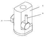
図1〜図2は、本発明による引張り試験機の一実施形態を示すものであり、1はボルトを通すことができる筒塔架台で、筒塔架台1内のハウジング部2には四角筒体の挟持台3が横に配置されてなる。該挟持台3にあっては中央近傍の上面aと底面bにボルトが貫通できる貫通孔4が設けられてなる。そして、該挟持台3の一端の両側面に支点孔5が設けられて軸のピン6を介してその一端が支えられてなる。これに相対する他端の上面部にはカムシャフト7が配置されてなり、このカムシャフト7の主軸と連体する軸端のそれぞれに回転レバー8とカムシャフト接続部9が筒塔架台1の外側に設けられてなる。さらに、この相対する他端では、上面部に配置されたカムシャフト7の逆回転を防止するためのプッシュロットのようなスプリング10と、底面部からは挟持台3押し上げるためのスプリング11にて支えられた構造となっている。また、挟持台3の上面aと底面bに設けてなるボルトの貫通孔4は、垂直から軸ズレする位置で設けられてなり、貫通孔4のエッジでボルトを挟持し易くなっている。Next, embodiments of the present invention will be described in detail with reference to the drawings.
1 to 2 show an embodiment of a tensile testing machine according to the present invention.
従って、構造物に固定されるボルトに対し、本発明は筒塔架台1をボルトに差し込んで、該架台1を構造物面Aに押し当てながら回転レバー8を軽く回して回転レバー8の軸と連体するハウジング部2内のカムシャフト7を回転させて、挟持台3の傾斜を変位させて、挟持台3に設けられた上面aと底面bの貫通孔4のエッジでボルトを挟持させる。次いで、トルクレンチ接続部9にトルクレンチをセットして軸と連体するカムシャフト7をさらに回転させて、加わるトルクをトルクレンチで読み取ることでボルトの固定強度を測定することができ、回転レバーを戻すことによりボルトの挟持が解放されるという引張り試験機である。 Therefore, the present invention inserts the
さらには、挟持台3に設けられてなる貫通孔4が垂直から軸ズレする位置で設けることにより、貫通孔4のエッジでボルトをさらに確実に挟み持つことができる。この時の挟持台3の傾斜が変位して生じる挟持台3の移動を妨げないように、挟持台3の両側面に設けられた支点孔5がピン6に対して緩やかな大きめの支点孔5として設けられピン6との支点が移動できるように構成されてなる。 Furthermore, by providing the through hole 4 provided in the holding table 3 at a position where the axis is displaced from the vertical, the bolt can be more securely held at the edge of the through hole 4. At this time, the
因みに、天井の構造物に埋め込まれたボルトの200mm長のネジボルトに対して、本発明の引張り試験機の回転レバーを開放の位置でネジボルトに差し込み、次に回転レバーを固定の位置に回して仮止めしてから(この時点で両手は解放される)、トルクレンチ接続部に表示型トルクレンチをセットして締め付けて、ネジボルトが引張られる力をトルク値として150キログラムの測定値を確認した。そこでトルクレンチの締め付けを止め、回転レバーを開放の位置に戻して、本発明の引張り試験機をアンカーボルトから引き抜いた。この一連の作業に要する時間は、大凡引張り試験機のセットで数秒、測定作業で数秒程度という迅速かつ簡単にボルトの固定強度が測定できた。 By the way, for the 200 mm long screw bolt embedded in the ceiling structure, insert the rotary lever of the tensile tester of the present invention into the screw bolt in the open position, and then turn the rotary lever to the fixed position to temporarily After stopping (both hands are released at this time), a display type torque wrench was set and tightened on the torque wrench connection, and the measured value of 150 kilograms was confirmed using the force with which the screw bolt is pulled as the torque value. Therefore, tightening of the torque wrench was stopped, the rotating lever was returned to the open position, and the tensile tester of the present invention was pulled out from the anchor bolt. The time required for this series of operations was approximately a few seconds with a set of tensile testers and several seconds with a measurement operation, and the bolt fixing strength could be measured quickly and easily.
1・・・筒塔架台
2・・・ハウジング部
3・・・挟持台
a・・・挟持台の上面
b・・・挟持台の低面
4・・・貫通孔
5・・・支点孔
6・・・ピン
7・・・カムシャフト
8・・・回転レバー
9・・・トルクレンチ接続部
10・・スプリング
11・・スプリング
A・・・構造物DESCRIPTION OF
Claims (2)
Priority Applications (1)
| Application Number | Priority Date | Filing Date | Title |
|---|---|---|---|
| JP2011269438A JP5370789B2 (en) | 2011-11-21 | 2011-11-21 | Tensile testing machine |
Applications Claiming Priority (1)
| Application Number | Priority Date | Filing Date | Title |
|---|---|---|---|
| JP2011269438A JP5370789B2 (en) | 2011-11-21 | 2011-11-21 | Tensile testing machine |
Publications (3)
| Publication Number | Publication Date |
|---|---|
| JP2013108968A JP2013108968A (en) | 2013-06-06 |
| JP2013108968A5 JP2013108968A5 (en) | 2013-08-01 |
| JP5370789B2 true JP5370789B2 (en) | 2013-12-18 |
Family
ID=48705847
Family Applications (1)
| Application Number | Title | Priority Date | Filing Date |
|---|---|---|---|
| JP2011269438A Expired - Fee Related JP5370789B2 (en) | 2011-11-21 | 2011-11-21 | Tensile testing machine |
Country Status (1)
| Country | Link |
|---|---|
| JP (1) | JP5370789B2 (en) |
Families Citing this family (3)
| Publication number | Priority date | Publication date | Assignee | Title |
|---|---|---|---|---|
| JP6459838B2 (en) * | 2015-07-16 | 2019-01-30 | 一文機工株式会社 | Tensile testing machine |
| CN113670724A (en) * | 2021-08-24 | 2021-11-19 | 江苏耀晶生物科技有限公司 | Tensile strength detection device is used in production of butadiene fine gloves |
| CN116008062B (en) * | 2022-12-12 | 2023-11-14 | 弘凯不锈钢科技(南通)有限公司 | Automatic change steel wire quality detection device |
Family Cites Families (4)
| Publication number | Priority date | Publication date | Assignee | Title |
|---|---|---|---|---|
| JPH1048112A (en) * | 1996-08-02 | 1998-02-20 | Fujita Corp | Test of pull-out strength of anchor bolt for machinery |
| JP2004093315A (en) * | 2002-08-30 | 2004-03-25 | Chiyoda Maintenance Kk | Apparatus for testing strength of member |
| JP3859655B2 (en) * | 2004-03-29 | 2006-12-20 | 大和ハウス工業株式会社 | testing machine |
| JP2006275898A (en) * | 2005-03-30 | 2006-10-12 | Japan Drive-It Co Ltd | Inspecting apparatus for tension load of anchoring tool |
-
2011
- 2011-11-21 JP JP2011269438A patent/JP5370789B2/en not_active Expired - Fee Related
Also Published As
| Publication number | Publication date |
|---|---|
| JP2013108968A (en) | 2013-06-06 |
Similar Documents
| Publication | Publication Date | Title |
|---|---|---|
| US11105444B2 (en) | Frangible hanger assembly and method | |
| EP3557209A1 (en) | Pulling device | |
| US20060207337A1 (en) | Apparatuses and methods for structurally testing fasteners | |
| JP5370789B2 (en) | Tensile testing machine | |
| US9605703B2 (en) | Clamp device for vertical pump coupling alignment | |
| CN111307387A (en) | Bolt transverse load and axial load test clamp and test method thereof | |
| CN102012345A (en) | Universal clamping mechanism for bolt/nut mechanical test | |
| US7757540B2 (en) | Device and method for testing torque wrenches | |
| CN109490101B (en) | Bolt screwing tool groove turning and screwing performance test device and test method thereof | |
| JP2004093315A (en) | Apparatus for testing strength of member | |
| CN113790957A (en) | Mechanical property test method under long-term coupling of corrosion and tensile stress | |
| JP6459838B2 (en) | Tensile testing machine | |
| JP2006275898A (en) | Inspecting apparatus for tension load of anchoring tool | |
| KR20120012842A (en) | On-Line Evaluation Technique of the Spring Support | |
| CN210293512U (en) | Lightning arrester fixing support tension testing device | |
| CN201945501U (en) | General clamping mechanism for mechanical test of bolts/nuts | |
| CN115420494A (en) | Integrated brake oil pipe threaded joint and bolt fastening performance testing machine | |
| KR101300589B1 (en) | Manual testing apparatus for testing strength of concrete | |
| JP2002267593A (en) | Method for testing anchor body, method for adjusting, and supporting table and load cell used in these methods | |
| CN104236783A (en) | Detecting trolley of hydraulic torque wrench | |
| CZ2012284A3 (en) | System for measuring elongation of bolts at simultaneous torque tightening by a torque spanner | |
| KR20180134046A (en) | Apparatus for adjusting interval of pipe | |
| JP2011157985A (en) | Piping support structure, piping support tool, and method of supporting piping | |
| CN107449659A (en) | A kind of fatigue test clamper | |
| JP4439703B2 (en) | Shear strength test measurement method and test measurement device |
Legal Events
| Date | Code | Title | Description |
|---|---|---|---|
| A871 | Explanation of circumstances concerning accelerated examination |
Free format text: JAPANESE INTERMEDIATE CODE: A871 Effective date: 20130517 |
|
| A521 | Request for written amendment filed |
Free format text: JAPANESE INTERMEDIATE CODE: A523 Effective date: 20130517 |
|
| A621 | Written request for application examination |
Free format text: JAPANESE INTERMEDIATE CODE: A621 Effective date: 20130517 |
|
| A521 | Request for written amendment filed |
Free format text: JAPANESE INTERMEDIATE CODE: A523 Effective date: 20130705 |
|
| TRDD | Decision of grant or rejection written | ||
| A975 | Report on accelerated examination |
Free format text: JAPANESE INTERMEDIATE CODE: A971005 Effective date: 20130815 |
|
| A01 | Written decision to grant a patent or to grant a registration (utility model) |
Free format text: JAPANESE INTERMEDIATE CODE: A01 Effective date: 20130827 |
|
| A61 | First payment of annual fees (during grant procedure) |
Free format text: JAPANESE INTERMEDIATE CODE: A61 Effective date: 20130904 |
|
| R150 | Certificate of patent or registration of utility model |
Ref document number: 5370789 Country of ref document: JP Free format text: JAPANESE INTERMEDIATE CODE: R150 Free format text: JAPANESE INTERMEDIATE CODE: R150 |
|
| R250 | Receipt of annual fees |
Free format text: JAPANESE INTERMEDIATE CODE: R250 |
|
| R250 | Receipt of annual fees |
Free format text: JAPANESE INTERMEDIATE CODE: R250 |
|
| R250 | Receipt of annual fees |
Free format text: JAPANESE INTERMEDIATE CODE: R250 |
|
| R250 | Receipt of annual fees |
Free format text: JAPANESE INTERMEDIATE CODE: R250 |
|
| R250 | Receipt of annual fees |
Free format text: JAPANESE INTERMEDIATE CODE: R250 |
|
| R250 | Receipt of annual fees |
Free format text: JAPANESE INTERMEDIATE CODE: R250 |
|
| LAPS | Cancellation because of no payment of annual fees |