JP5369485B2 - Game machine - Google Patents
Game machine Download PDFInfo
- Publication number
- JP5369485B2 JP5369485B2 JP2008117125A JP2008117125A JP5369485B2 JP 5369485 B2 JP5369485 B2 JP 5369485B2 JP 2008117125 A JP2008117125 A JP 2008117125A JP 2008117125 A JP2008117125 A JP 2008117125A JP 5369485 B2 JP5369485 B2 JP 5369485B2
- Authority
- JP
- Japan
- Prior art keywords
- command
- payout
- game
- control device
- winning
- Prior art date
- Legal status (The legal status is an assumption and is not a legal conclusion. Google has not performed a legal analysis and makes no representation as to the accuracy of the status listed.)
- Active
Links
Images


Landscapes
- Pinball Game Machines (AREA)
Abstract
Description
本発明は、遊技機に関するものである。
The present invention relates to a gaming machine.
パチンコ機の中には、遊技の制御負担を分散するべく、主制御装置に遊技の主な制御を行わせ、その主制御装置とは別に、遊技球の払い出しを行う払出制御装置などの周辺制御装置を設け、これらの周辺制御装置に対して、主制御装置からコマンドなどを出力して制御をするように構成したものがある。
Some pachinko machine, so as to distribute the control load of the game, the main control device to perform the main control of the game, apart from its main controller, a peripheral such as a payout control equipment which pays out game balls There is a configuration in which a control device is provided and these peripheral control devices are controlled by outputting commands or the like from the main control device.
しかしながら、例えば、周辺制御装置は、主制御装置から出力されるコマンドなどに基づいて制御されるので、不正行為などが行われることにより異常な遊技状態の下で主制御装置からコマンドなどが出力された場合であっても、そのコマンドなどに基づいて制御が行われてしまう。
However, for example, the peripheral controller, since it is controlled on the basis of such a command output from the main control device, such as a command is output from the main control unit under abnormal gaming state by like fraud carried out even when an, control will be performed on the basis of such on the command.
具体的には、例えば、当たり時に開放される特定入賞口を覆う開閉扉を常時開放状態にする不正行為などが行われた場合には、特定入賞口に遊技球が入賞してしまうので、当たり時でないにも拘らず、主制御装置から賞球の払出を指示するコマンドなどが出力され、払出制御装置から所定個数の賞球(遊技球)が払い出されてしまう。
Specifically, for example, because if the illegal act of the normally open state closing door for covering a particular winning hole to be opened when the person have enough has been performed, the game ball to a particular winning hole results in winning, despite not during those have enough, the main control unit such as a command is output which instructs the payout of prize balls from a predetermined number of prize balls from payout controller (game balls) will be paid out.
上述のように、払出制御装置に代表される周辺制御装置は、主制御装置から出力されるコマンドなどに基づいて制御されるので、主制御装置からコマンドなどが出力された場合には、そのコマンドなどが異常な遊技状態の下で設定されたものであっても(不正行為などが行われた下で設定されたものであっても)、このコマンドなどに基づいて制御が行われてしまうという問題点があった。
As described above, when the peripheral control device represented by a dispensing control unit, since it is controlled on the basis or the commands output from the main controller, etc. command is output from the main controller, the command be those, etc. are set under abnormal gaming state (even those that have been set under the like fraud has been performed), that is controlled on the basis like this command will be performed There was a problem.
本発明は、上記例示した問題点等を解決するためになされたものであり、主制御手段から送信される特別入賞口への入賞に基づく払出コマンドが所定の遊技価値が付与されていない遊技状態の下で設定されたものである場合には、この払出コマンドに基づいて周辺制御手段により遊技媒体が払い出されることを防止することができる遊技機を提供することを目的としている。
The present invention has been made in order to solve the above-described problems and the like, and a gaming state in which a payout command based on winning in a special winning opening transmitted from the main control means is not given a predetermined gaming value If it is set under the above, it is an object to provide a gaming machine that can prevent the gaming media from being paid out by the peripheral control means based on this payout command.
この目的を達成するために請求項1記載の遊技機は、遊技に関する主な制御を行う主制御手段と、その主制御手段から送信されるコマンドに基づいて前記遊技に関する周辺制御を行う周辺制御手段と、前記遊技に使用される遊技媒体が入賞する入賞口と、その入賞口への前記遊技媒体の入賞を検出する入賞検出手段と、その入賞検出手段により遊技媒体の入賞が検出された場合に、所定の遊技価値を付与するかを抽選する前記主制御手段が有する抽選手段と、その抽選手段により所定の遊技価値が付与される結果となり、その結果に基づいて所定の遊技価値が付与される場合に、前記遊技媒体の入賞が可能となる特別入賞口と、その特別入賞口への遊技媒体の入賞を検出する特別入賞検出手段とを備えるものであり、前記主制御手段は、前記入賞検出手段により前記入賞口への遊技媒体の入賞が検出された場合と、前記特別入賞検出手段により前記特別入賞口への遊技媒体の入賞が検出された場合とに、その検出された入賞に基づいた数の遊技媒体の払い出しの指示を、前記周辺制御手段へ送信する前記コマンドである払出コマンドとして設定する払出コマンド設定手段と、その払出コマンド設定手段により設定された払出コマンドを前記周辺制御手段へ送信する払出コマンド送信手段と、前記所定の遊技価値が付与されている期間中、その所定の遊技価値が付与されている状態を示す遊技価値付与状態情報を前記周辺制御手段へ送信する遊技価値付与状態情報送信手段とを備え、前記周辺制御手段は、前記払出コマンド送信手段により送信された前記払出コマンドを受信する払出コマンド受信手段と、その払出コマンド受信手段により受信された前記払出コマンドに基づいて、遊技媒体の払い出しを実行する払出実行手段と、前記遊技価値付与状態情報送信手段により送信された前記遊技価値付与状態情報を受信する遊技価値付与状態情報受信手段と、その遊技価値付与状態情報受信手段により受信された遊技価値付与状態情報が示す遊技状態と、前記払出コマンド受信手段により受信した前記払出コマンドとに基づいて、その払出コマンドが前記特別入賞口への入賞に基づく払出コマンドであり、所定の遊技価値が付与されていない遊技状態の下で前記払出コマンド設定手段によって設定された異常な払出コマンドかを判定する払出コマンド判定手段と、その払出コマンド判定手段により、前記払出コマンド受信手段により受信した払出コマンドが異常な払出コマンドと判定された場合に、前記払出実行手段による遊技媒体の払い出しを禁止し、その異常な払出コマンドを無効化する払出禁止手段とを備え、前記主制御手段は、前記遊技価値付与状態情報送信手段による遊技価値付与状態情報の送信開始および送信停止の指示に基づいて、その送信開始から送信停止までの期間中、遊技価値付与状態情報を送信し続ける遊技価値付与状態情報送信継続手段と、その遊技価値付与状態情報送信継続手段から送信される遊技価値付与状態情報の前記周辺制御手段への送信を仲介する遊技価値付与状態情報仲介手段と、前記遊技価値付与状態情報送信継続手段と前記遊技価値付与状態情報仲介手段との間において前記遊技価値付与状態情報送信継続手段から前記周辺制御手段へ送信される遊技価値付与状態情報を遊技機の外部に設けられた外部装置へも送信する外部送信手段とを備えている。
In order to achieve this object, the gaming machine according to
請求項1記載の遊技機によれば、特別入賞口への入賞に基づく払出コマンドが所定の遊技価値が付与されていない遊技状態の下で設定された場合には、この払出コマンドに基づいて遊技媒体が払い出されることを防止することができるという効果がある。
According to the gaming machine of the first aspect, when a payout command based on a winning at a special winning opening is set under a gaming state where a predetermined game value is not given, a game is played based on the payout command. There is an effect that the medium can be prevented from being dispensed .
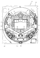
以下、パチンコ遊技機(以下、単に「パチンコ機」という)の一実施形態を、図面に基づいて説明する。図1はパチンコ機10の正面図であり、図2はパチンコ機10の遊技盤13の正面図であり、図3はパチンコ機10の背面図である。
Hereinafter, an embodiment of a pachinko gaming machine (hereinafter simply referred to as “pachinko machine”) will be described with reference to the drawings. 1 is a front view of the
図1に示すように、パチンコ機10は、略矩形状に組み合わせた木枠により外殻が形成される外枠11と、その外枠11と略同一の外形形状に形成され、外枠11に対して開閉可能に支持された内枠12とを備えている。外枠11には、内枠12を支持するために正面視(図1参照)左側の上下2カ所に金属製のヒンジ18が取り付けられ、そのヒンジ18が設けられた側を開閉の軸として内枠12が正面手前側へ開閉可能に支持されている。
As shown in FIG. 1, the
内枠12には、多数の釘や入賞口63,64等を有する遊技盤13(図2参照)が裏面側から着脱可能に装着される。この遊技盤13の前面を球が流下することにより弾球遊技が行われる。なお、内枠12には、球を遊技盤13の前面領域に発射する球発射ユニット112a(図4参照)やその球発射ユニット112aから発射された球を遊技盤13の前面領域まで誘導する発射レール(図示せず)等が取り付けられている。
A game board 13 (see FIG. 2) having a large number of nails, winning
内枠12の前面側には、その前面上側を覆う前面枠14と、その下側を覆う下皿ユニット15とが設けられている。前面枠14及び下皿ユニット15を支持するために正面視(図1参照)左側の上下2カ所に金属製のヒンジ19が取り付けられ、そのヒンジ19が設けられた側を開閉の軸として前面枠14及び下皿ユニット15が正面手前側へ開閉可能に支持されている。なお、内枠12の施錠と前面枠14の施錠とは、シリンダ錠20の鍵穴21に専用の鍵を差し込んで所定の操作を行うことでそれぞれ解除される。
On the front side of the
前面枠14は、装飾用の樹脂部品や電気部品等を組み付けたものであり、その略中央部には略楕円形状に開口形成された窓部14cが設けられている。前面枠14の裏面側には2枚の板ガラスを有するガラスユニット16が配設され、そのガラスユニット16を介して遊技盤13の前面がパチンコ機10の正面側に視認可能となっている。前面枠14には、球を貯留する上皿17が前方へ張り出して上面を開放した略箱状に形成されており、この上皿17に賞球や貸出球などが排出される。上皿17の底面は正面視(図1参照)右側に下降傾斜して形成され、その傾斜により上皿17に投入された球が球発射ユニット112aへと案内される。また、上皿17の上面には、枠ボタン22が設けられている。この枠ボタン22は、例えば、第3図柄表示装置81(図2参照)で表示される変動表示の演出パターンを変更したり、リーチ演出時の演出内容を変更したりする場合などに、遊技者により操作される。
The
加えて、前面枠14には、その周囲(例えばコーナー部分)に各種ランプ等の発光手段が設けられている。これら発光手段は、大当たり時や所定のリーチ時等における遊技状態の変化に応じて、点灯又は点滅することにより発光態様が変更制御され、遊技中の演出効果を高める役割を果たす。窓部14cの周縁には、LED等の発光手段を内蔵した電飾部29〜33が設けられている。パチンコ機10においては、これら電飾部29〜33が大当たりランプ等の演出ランプとして機能し、大当たり時やリーチ演出時等には内蔵するLEDの点灯や点滅によって各電飾部29〜33が点灯または点滅して、大当たり中である旨、或いは大当たり一歩手前のリーチ中である旨が報知される。
In addition, the
また、前面枠14の正面視(図1参照)左上部には、LED等の発光手段が内蔵され賞球の払い出し中とエラー発生時とを表示可能な表示ランプ34が設けられている。また、右側の電飾部32下側には、前面枠14の裏面側を視認できるように裏面側より透明樹脂を取り付けて小窓35が形成され、遊技盤13前面の貼着スペースK1(図2参照)に貼付される証紙等はパチンコ機10の前面から視認可能とされている。また、パチンコ機10においては、より煌びやかさを醸し出すために、電飾部29〜33の周りの領域にクロムメッキを施したABS樹脂製のメッキ部材36が取り付けられている。
Further, in the upper left part of the
窓部14cの下方には、貸球操作部40が配設されている。貸球操作部40には、度数表示部41と、球貸しボタン42と、返却ボタン43とが設けられている。パチンコ機10の側方に配置されるカードユニット(球貸しユニット)(図示せず)に紙幣やカード等を投入した状態で貸球操作部40が操作されると、その操作に応じて球の貸出が行われる。具体的には、度数表示部41はカード等の残額情報が表示される領域であり、内蔵されたLEDが点灯して残額情報として残額が数字で表示される。球貸しボタン42は、カード等(記録媒体)に記録された情報に基づいて貸出球を得るために操作されるものであり、カード等に残額が存在する限りにおいて貸出球が上皿17に供給される。返却ボタン43は、カードユニットに挿入されたカード等の返却を求める際に操作される。なお、カードユニットを介さずに球貸し装置等から上皿17に球が直接貸し出されるパチンコ機、いわゆる現金機では貸球操作部40が不要となるが、この場合には、貸球操作部40の設置部分に飾りシール等を付加して部品構成は共通のものとしても良い。カードユニットを用いたパチンコ機と現金機との共通化を図ることができる。
A ball
上皿17の下側に位置する下皿ユニット15には、その中央部に上皿17に貯留しきれなかった球を貯留するための下皿50が上面を開放した略箱状に形成されている。下皿50の右側には、球を遊技盤13の前面へ打ち込むために遊技者によって操作される操作ハンドル51が配設され、かかる操作ハンドル51の内部には球発射ユニット112aの駆動を許可するためのタッチセンサ(図示せず)と、操作ハンドル51の回動操作量を電気抵抗の変化により検出する可変抵抗器(図示せず)とが内蔵されている。操作ハンドル51が遊技者によって右回りに回転操作されると、タッチセンサがオンされると共に可変抵抗器の抵抗値が操作量に対応して変化し、操作ハンドル51の回動操作量に応じて変化する可変抵抗器の抵抗値に対応した強さで球が発射され、これにより遊技者の操作に対応した飛び量で遊技盤13の前面へ球が打ち込まれる。
In the
下皿50の正面下方部には、下皿50に貯留された球を下方へ排出する際に操作するための球抜きレバー52が設けられている。この球抜きレバー52は、常時、右方向に付勢されており、その付勢に抗して左方向へスライドさせることにより、下皿50の底面に形成された底面口が開口して、その底面口から球が自然落下して排出される。かかる球抜きレバー52の操作は、通常、下皿50の下方に下皿50から排出された球を受け取る箱(一般に「千両箱」と称される)を置いた状態で行われる。下皿50の右方には、前述したように操作ハンドル51が配設され、下皿50の左方には灰皿53が取り付けられている。
In the lower part of the front of the
図2に示すように、遊技盤13は、正面視略正方形状に切削加工した木製のベース板60に、球案内用の多数の釘や風車およびレール61,62、一般入賞口63、第1入球口64、可変入賞装置65、可変表示装置ユニット80等を組み付けて構成され、その周縁部が内枠12の裏面側に取り付けられる。一般入賞口63、第1入球口64、可変入賞装置65、可変表示装置ユニット80は、ルータ加工によってベース板60に形成された貫通穴に配設され、遊技盤13の前面側から木ネジ等により固定されている。また、遊技盤13の前面中央部分は、前面枠14の窓部14cを通じて内枠13の前面側から視認することができる。以下に、遊技盤13の構成について説明する。
As shown in FIG. 2, the
遊技盤13の前面には、帯状の金属板を略円弧状に屈曲加工して形成した外レール62が植立され、その外レール62の内側位置には外レール62と同様に帯状の金属板で形成した円弧状の内レール61が植立される。この内レール61と外レール62とにより遊技盤13の前面外周が囲まれ、遊技盤13とガラスユニット16とにより前後が囲まれることにより、遊技盤13の前面には、球の挙動により遊技が行われる遊技領域が形成される。遊技領域は、遊技盤13の前面であって2本のレール61,62と円弧部材70とにより区画して形成される略円形状の領域である。
An
2本のレール61,62は、球発射ユニット112aから発射された球を遊技盤13上部へ案内するために設けられたものである。内レール61の先端部分(図2の左上部)には戻り球防止部材68が取り付けられ、一旦、遊技盤13の上部へ案内された球が再度球案内通路内に戻ってしまうといった事態が防止される。外レール62の先端部(図2の右上部)には、球の最大飛翔部分に対応する位置に返しゴム69が取り付けられ、所定以上の勢いで発射された球は、返しゴム69に当たって、勢いが減衰されつつ中央部側へ跳ね返される。また、内レール61の右下側の先端部と外レール62の右上側の先端部との間には、レール間を繋ぐ円弧を内面側に設けて形成された樹脂製の円弧部材70がベース板60に打ち込んで固定されている。
The two
遊技領域の正面視右側上部(図2の右側上部)には、発光手段である複数のLED37aと7セグメント表示器37bとが設けられた第1図柄表示装置37が配設されている。第1図柄表示装置37は、主制御装置110で行われる各制御に応じた表示がなされるものであり、主にパチンコ機10の遊技状態の表示が行われる。
A first
複数のLED37aは、パチンコ機10が、確変中であるか、時短中であるか、通常中であるかを、点灯状態により示したり、変動中であるか否かを点灯状態により示したり、停止図柄が確変大当たりに対応した図柄か、普通大当たりに対応した図柄か、外れ図柄であるかを、点灯状態により示したり、保留球数を点灯状態により示すものである。7セグメント表示装置37bは、大当たり中のラウンド数やエラー表示を行うものである。LED37aは、それぞれLEDの発光色(例えば、赤、緑、青)が異なるよう構成され、その発光色の組合わせにより、少ない数のLEDでパチンコ機10の各種遊技状態を示唆することができる。
The plurality of
なお、上述したパチンコ機10が確変中であるとは、大当たり確率がアップして特別遊技状態へ移行し易い状態である。本実施の形態の確変中は、更に、第2図柄の当たり確率がアップして第1入球口64へ球が入球し易い遊技の状態である。また、パチンコ機10が時短中であるとは、大当たり確率がそのままで第2図柄の当たり確率のみがアップして第1入球口64へ球が入球し易い状態の遊技中であり、パチンコ機10が通常中であるとは、確変中および時短中でない遊技中(大当たり確率も第2図柄の当たり確率もアップしていない状態)である。また、パチンコ機10の遊技状態に応じて、第1入球口64に付随する電動役物(図示せず)が開放する時間や、1回の当たりで開放する回数を変更するものとしても良い。
It should be noted that the fact that the
遊技領域には、球が入賞することにより5個から15個の球が賞球として払い出される複数の一般入賞口63が配設されている。また、遊技領域の中央部分には、可変表示装置ユニット80が配設されている。可変表示装置ユニット80には、第1入球口64への入賞をトリガとして第3図柄を変動表示する液晶ディスプレイ(以下「LCD」と略す。)で構成された第3図柄表示装置81と、第2入球口67の球の通過をトリガとして第2図柄を変動表示する発光ダイオード(以下「LED」と略す。)で構成される第2図柄表示装置82とが設けられている。
The game area is provided with a plurality of general winning
第3図柄表示装置81は、後述する表示制御装置114によって表示内容が制御され、例えば左、中及び右の3つの図柄列が表示される。各図柄列は複数の図柄によって構成され、これらの図柄が図柄列毎に縦スクロールして第3図柄表示装置81の表示画面上にて第3図柄が可変表示されるようになっている。また、本実施の形態では、第3図柄表示装置81は8インチサイズの大型のLCDで構成され、可変表示装置ユニット80には、この第3図柄表示装置81の外周を囲むようにして、センターフレーム86が配設されている。本実施の形態の第3図柄表示装置81は、主制御装置110の制御に伴った遊技状態の表示が第1図柄表示装置37で行われるのに対して、その第1図柄表示装置37の表示に応じた装飾的な表示を行うものである。なお、LCDに代えて、例えば、リール等を用いて第3図柄表示装置81を構成しても良い。
The display content of the third
第1図柄表示装置37にて停止図柄(確変大当たり図柄、普通大当たり図柄、外れ図柄のいずれか1つ)が表示されるまでの間に球が第1入球口64へ入球した場合、その入球回数は最大4回まで保留され、その保留回数は第1図柄表示装置37により示されると共に保留ランプ85の点灯個数においても示される。保留ランプ85は、最大保留数分の4つ設けられ、第3図柄表示装置81の上方に左右対称に配設されている。なお、本実施形態においては、第1入球口64への入賞は、最大4回まで保留されるように構成したが、最大保留回数は4回に限定されるものでなく、3回以下、又は、5回以上の回数(例えば、8回)に設定しても良い。また、保留ランプ85を削除し、第1入球口64への入賞に基づく変動表示の保留回数を第3図柄表示装置81の一部に数字で、或いは、4つに区画された領域を保留回数分だけ異なる態様(例えば、色や点灯パターン)にして表示するようにしても良い。また、第1図柄表示装置37により保留回数が示されるので、保留ランプ85による点灯表示を行わないものとしても良い。
If a ball enters the
第2図柄表示装置82は、第2図柄の表示部83と保留ランプ84とを有し、球が第2入球口67を通過する毎に、表示部83において表示図柄(第2図柄)としての「○」の図柄と「×」の図柄とが交互に点灯して変動表示が行われ、その変動表示が所定図柄(本実施形態においては「○」の図柄)で停止した場合に第1入球口64が所定時間だけ作動状態となる(開放される)よう構成されている。球の第2入球口67の通過回数は最大4回まで保留され、その保留回数が上述した第1図柄表示装置37により表示されると共に保留ランプ84においても点灯表示される。なお、第2図柄の変動表示は、本実施の形態のように、表示部83において複数のランプの点灯と非点灯を切り換えることにより行うものの他、第1図柄表示装置37及び第3図柄表示装置81の一部を使用して行うようにしても良い。同様に、保留ランプ84の点灯を第3図柄表示装置81の一部で行うようにしても良い。また、第2入球口67の通過は、第1入球口64と同様に、最大保留回数は4回に限定されるものでなく、3回以下、又は、5回以上の回数(例えば、8回)に設定しても良い。また、第1図柄表示装置37により保留回数が示されるので、保留ランプ84による点灯表示を行わないものとしても良い。
The second
可変表示装置ユニット80の下方には、球が入球し得る第1入球口64が配設されている。この第1入球口64へ球が入球すると遊技盤13の裏面側に設けられる第1入球口スイッチ(図示せず)がオンとなり、その第1入球口スイッチのオンに起因して主制御装置110で大当たりの抽選がなされ、その抽選結果に応じた表示が第1図柄表示装置37のLED37aで示される。また、第1入球口64は、球が入球すると5個の球が賞球として払い出される入賞口の1つにもなっている。
Below the variable
第1入球口64の下方には可変入賞装置65が配設されており、その略中央部分に横長矩形状の特定入賞口(大開放口)65aが設けられている。パチンコ機10においては、主制御装置110での抽選が大当たりとなると、所定時間(変動時間)が経過した後に、大当たりの停止図柄となるよう第1図柄表示装置37のLED37aを点灯させると共に、その大当たりに対応した停止図柄を第3図柄表示装置81に表示させて、大当たりの発生が示される。その後、球が入賞し易い特別遊技状態(大当たり演出中)に遊技状態が遷移する。この特別遊技状態として、通常時には閉鎖されている特定入賞口65aが、所定時間(例えば、30秒経過するまで、或いは、球が10個入賞するまで)開放される。
A variable winning
この特定入賞口65aは、所定時間が経過すると閉鎖され、その閉鎖後、再度、その特定入賞口65aが所定時間開放される。この特定入賞口65aの開閉動作は、最高で例えば16回(16ラウンド)繰り返し可能にされている。この開閉動作が行われている状態が、遊技者にとって有利な特別遊技状態の一形態であり、遊技者には、遊技上の価値(遊技価値)の付与として通常時より多量の賞球の払い出しが行われる。
The
可変入賞装置65は、具体的には、特定入賞口65aを覆う横長矩形状の開閉板と、その開閉板の下辺を軸として前方側に開閉駆動するためのソレノイドとを備えている。特定入賞口65aは、通常時は、球が入賞できないか又は入賞し難い閉状態になっている。大当たりの際にはソレノイドを駆動して開閉板を前面下側に傾倒し、球が特定入賞口65aに入賞しやすい開状態を一時的に形成し、その開状態と通常時の閉状態との状態を交互に繰り返すように作動する。
Specifically, the variable winning
なお、上記した形態に特別遊技状態は限定されるものではない。特定入賞口65aとは別に開閉される大開放口を遊技領域に設け、第1図柄表示装置37において大当たりに対応したLED37aが点灯した場合に、特定入賞口65aが所定時間開放され、その特定入賞口65aの開放中に、球が特定入賞口65a内へ入賞することを契機として特定入賞口65aとは別に設けられた大開放口が所定時間、所定回数開放される遊技状態を特別遊技状態として形成するようにしても良い。
Note that the special gaming state is not limited to the above-described form. When the game area is provided with a large opening that is opened and closed separately from the specific winning
遊技盤13の下側における左右の隅部には、証紙や識別ラベル等を貼着するための貼着スペースK1,K2が設けられ、貼着スペースK1に貼られた証紙等は、前面枠14の小窓35を通じて視認することができる。
Adhesive spaces K1, K2 for adhering certificate papers, identification labels, etc. are provided at the left and right corners on the lower side of the
さらに、遊技盤13には、アウト口66と第2入球口(スルーゲート)67とが設けられている。いずれの入賞口63,64,65aにも入球しなかった球はアウト口66を通って図示しない球排出路へと案内される。遊技盤13には、球の落下方向を適宜分散、調整等するために多数の釘が植設されているとともに、風車等の各種部材(役物)が配設されている。
Further, the
図3に示すように、パチンコ機10の背面側には、制御基板ユニット90,91と、裏パックユニット94とが主に備えられている。制御基板ユニット90は、主制御基板(主制御装置110)と音声ランプ制御基板(音声ランプ制御装置113)と表示制御基板(表示制御装置114)とが搭載されてユニット化されている。制御基板ユニット91は、払出制御基板(払出制御装置111)と発射制御基板(発射制御装置112)と電源基板(電源装置115)とカードユニット接続基板116とが搭載されてユニット化されている。裏パックユニット94は、保護カバー部を形成する裏パック92と払出ユニット93とがユニット化されている。なお、主制御装置110、音声ランプ制御装置113及び表示制御装置114、払出制御装置111及び発射制御装置112、電源装置115、カードユニット接続基板116は、それぞれ基板ボックス100〜104に収納されている。基板ボックス100〜104は、ボックスベースと該ボックスベースの開口部を覆うボックスカバーとを備えており、ボックスベースとボックスカバーとを連結して、各制御装置や各基板を収納している。
As shown in FIG. 3,
また、基板ボックス100(主制御装置110)及び基板ボックス102(払出制御装置111及び発射制御装置112)は、ボックスベースとボックスカバーとを封印ユニット(図示せず)によって開封不能に連結(かしめ構造による連結)している。また、ボックスベースとボックスカバーとの連結部には、ボックスベースとボックスカバーとに亘って封印シール(図示せず)を貼着している。この封印シールは、脆性な素材で構成されており、基板ボックス100,102を開封するために封印シールを剥がそうとしたり、基板ボックス100,102を無理に開封しようとすると、ボックスベース側とボックスカバー側とに切断される。よって、封印ユニット又は封印シールを確認することで、基板ボックス100,102が開封されたかどうかを知ることができる。
Further, the substrate box 100 (main control device 110) and the substrate box 102 (dispensing
払出ユニット93は、裏パックユニット94の最上部に位置して上方に開口したタンク130と、タンク130の下方に連結され下流側に向けて緩やかに傾斜するタンクレール131と、タンクレール131の下流側に縦向きに連結されるケースレール132と、ケースレール132の最下流部に設けられ、払出モータ216(図4参照)の所定の電気的構成により球の払出を行う払出装置133とを備えている。タンク130には、遊技ホールの島設備から供給される球が逐次補給され、払出装置133により必要個数の球の払い出しが適宜行われる。タンクレール131には、当該タンクレール131に振動を付加するためのバイブレータ134が取り付けられている。
The
また、払出制御装置111には、状態復帰スイッチ120と7セグメントLED121が設けられている。発射制御装置112には、可変抵抗器の操作つまみ122が設けられ、電源装置115にはRAM消去スイッチ123が設けられている。状態復帰スイッチ120は、例えば、払出モータ216(図4参照)部の球詰まり等、払出エラーの発生時に球詰まりを解消(正常状態への復帰)するために操作されるスイッチであり、7セグメントLED121は、払出制御装置111の状態を報知するための表示器である。また、操作つまみ122は、発射ソレノイドの発射力を調整するために操作される可変抵抗器である。RAM消去スイッチ123は、パチンコ機10を初期状態に戻したい場合に電源投入時に操作されるスイッチである。
The
次に、図4を参照して、本パチンコ機10の電気的構成について説明する。図4は、パチンコ機10の電気的構成を示したブロック図である。
Next, the electrical configuration of the
主制御装置110には、演算装置である1チップマイコンとしてのMPU201が搭載されている。MPU201には、該MPU201により実行される各種の制御プログラムや固定値データを記憶したROM202と、そのROM202内に記憶される制御プログラムの実行に際して各種のデータ等を一時的に記憶するためのメモリであるRAM203と、そのほか、割込回路やタイマ回路、データ送受信回路などの各種回路が内蔵されている。なお、払出制御装置111や音声ランプ制御装置113などの周辺制御装置(サブ制御装置)に対して動作を指示するために、データ送受信回路によって、主制御装置110から該サブ制御装置へ各種のコマンドが送信されるが、かかるコマンドは、主制御装置110からサブ制御装置へ一方向にのみ送信される。
The
RAM203は、MPU201の内部レジスタの内容やMPU201により実行される制御プログラムの戻り先番地などが記憶されるスタックエリアと、各種のフラグおよびカウンタ、I/O等の値が記憶される作業エリア(作業領域)とを備えている。RAM203は、パチンコ機10の電源の遮断後においても電源装置115からバックアップ電圧が供給されてデータを保持(バックアップ)できる構成となっており、RAM203に記憶されるデータは、すべてバックアップされる。
The
主制御装置110のMPU201には、アドレスバス及びデータバスで構成されるバスライン204を介して入出力ポート205が接続されている。入出力ポート205には、コネクタ207,217を介して払出制御装置111が、また、コネクタ208,228を介して音声ランプ制御装置113が、それぞれ接続されている。その他、入出力ポート205には、第1図柄表示装置37、第2図柄表示装置82や、図示しないスイッチ群やセンサ群などからなる各種スイッチ206や、特定入賞口65aの開閉板の下辺を軸として前方側に開閉駆動するための大開放口ソレノイドや電動役物を駆動するためのソレノイドなどからなるソレノイド209が接続されている。
An input /
また、主制御装置110のMPU201には、MPU201から出力された大当中パルス信号PSをラッチ回路272のD端子に出力する駆動回路であるドライバIC270の入力端子、およびMPU201から出力された制御パルス信号GSをラッチ回路272のG端子に出力する駆動回路であるドライバIC271の入力端子が接続されている。
Further, the
ラッチ回路272のD端子は、ドライバIC270の入力端子と接続され、ラッチ回路272のG端子は、ドライバIC271の入力端子と接続されている。また、ラッチ回路272のQ端子は、コネクタ273,274と接続されている。
The D terminal of the
ラッチ回路272は、D型ラッチであり、ドライバIC270からD端子へ大当中パルス信号PSが入力されている間に(D端子がハイ状態である間に)、ドライバIC271からG端子へ制御パルス信号GSが入力されると(G端子がハイ状態となると)、大当中信号SG3をQ端子から出力する(Q端子がハイ状態となる)。一方、ラッチ回路272は、ドライバIC270からD端子へ大当中パルス信号PSが出力されていない間に(D端子がロウ状態である間に)、ドライバIC271からG端子へ制御パルス信号GSが入力されると(G端子がハイ状態となると)、Q端子から出力していた大当中信号SG3を出力停止する(Q端子がロウ状態となる)。
The
ラッチ回路272のQ端子から出力された大当中信号SG3は、コネクタ273を介して、払出制御装置111のコネクタ275へ伝送され、払出制御装置111の入出力ポート215へ入力される。また、ラッチ回路272のQ端子から出力された大当中信号SG3は、コネクタ274を介して、外部出力端子板261に入力され、外部出力端子板261からホールコンピュータ262へ出力される。
The big hit signal SG3 output from the Q terminal of the
なお、ホールコンピュータ262は、パチンコ機10毎に設けられており、大当中信号SG3が入力されると、その入力時間や入力回数が記憶される。また、ホールコンピュータ262にはLED等の発光素子から構成される電飾装置が設けられており、大当中信号SG3がホールコンピュータ262へ入力されると、電飾装置を発光させて大当中信号SG3が入力中であることを、遊技者や遊技場の店員に報知することができる。
Note that the
よって、例えば、ラッチ回路272のQ端子とコネクタ273とを接続する信号線に、大当中信号SG3を常時出力する不正基板が接続された場合には、ホールコンピュータ262へ大当中信号SG3が常時出力されることとなる。従って、ホールコンピュータ262で大当中信号SG3の入力状況を確認することで、大当中信号SG3が常時出力されていることを検出することができる。これにより、例えば、ラッチ回路272のQ端子とコネクタ273とを接続する信号線に接続された不正基板を発見することができる。
Therefore, for example, when an illegal board that always outputs the big hit signal SG3 is connected to the signal line connecting the Q terminal of the
払出制御装置111は、払出モータ216を駆動させて賞球や貸出球の払出制御を行うものである。演算装置であるMPU211は、そのMPU211により実行される制御プログラムや固定値データ等を記憶したROM212と、ワークメモリ等として使用されるRAM213とを備えている。
The
払出制御装置111のRAM213は、主制御装置110のRAM203と同様に、MPU211の内部レジスタの内容やMPU211により実行される制御プログラムの戻り先番地などが記憶されるスタックエリアと、各種のフラグおよびカウンタ、I/O等の値が記憶される作業エリア(作業領域)とを備えている。RAM213は、パチンコ機10の電源の遮断後においても電源装置115からバックアップ電圧が供給されてデータを保持(バックアップ)できる構成となっており、RAM213に記憶されるデータは、すべてバックアップされる。
The
RAM213の作業エリアには、総賞球個数メモリ213aと、上位コマンド記憶バッファ213bと、払出エラーフラグ213cと、払出許可フラグ213dと、コマンド受信フラグ213eと、大当中信号出力フラグ213fと、大当中賞球エラーフラグ213gとが設けられている。
The work area of the
総賞球個数メモリ213aは、払出制御装置111が払い出すべき、未払いの賞球の総個数を記憶するメモリである。遊技領域へ打ち込まれた球が、いずれかの入賞口63,64,65aへ入賞し、これが主制御装置110で検出されると、その入賞に応じた数の賞球の払い出しが、賞球コマンド(図7参照)によって、主制御装置110から払出制御装置111に対して指示される(賞球コマンドが主制御装置110から払出制御装置111へ送信される)。総賞球個数メモリ213aには、該賞球コマンドで指示された賞球の払い出し数が加算され記憶される。総賞球個数メモリ213aの値が0でなければ、賞球の払い出しが行われ、払い出された賞球が払出検出センサ218で1個検出される毎に、その値が1減算される。賞球の払い出しは、総賞球個数メモリメモリ213aの値が0になるまで行われる。なお、特定入賞口65aに球が入賞した場合に限り、主制御装置110から払出制御装置111へ15個賞球払出コマンドが送信される。
The total prize
上位コマンド記憶バッファ213bは、図7に示す主制御装置110から払出制御装置111へ出力される2バイトのコマンドのうち、上位コマンド(1バイト目のコマンド)を記憶するバッファである。主制御装置110から払出制御装置111へは、払出復帰コマンドと、払出初期化コマンドと、15種類の賞球コマンドとが出力されるが、上位コマンド記憶バッファ213bには、これらの上位コマンド(99H,AAH,F0H〜FEH)のいずれかが記憶される。上位コマンド記憶バッファ213bの内容は、下位コマンド(2バイト目のコマンド)を入力すると、0クリアされる。
The upper
払出エラーフラグ213cは、図7に示す主制御装置110から払出制御装置111へ出力される2バイトのコマンドを、払出制御装置111が正常に入力できない場合にオンされるフラグである。払出エラーフラグ213cがオンされると、状態報知処理(図24参照)により、7セグメントLED121に「C」の文字が表示され、コマンドエラーの発生が報知される。一旦オンされた払出エラーフラグ213cは、2バイトの正常なコマンドを入力すると、オフされる。なお、払出エラーフラグ213cがオフされると、7セグメントLED121のエラー表示も解除される。
The
払出許可フラグ213dは、賞球や貸出球の払い出しを許可するためのフラグであり、立ち上げ処理においてオフされる一方(図17のS908,S911,S912)、主制御装置110から出力された正常なコマンド(払出初期化コマンド、払出復電コマンド、賞球コマンドなど)を入力すると、オンされる。即ち、払出許可フラグ213dは、主制御装置110が立ち上がっていることを確認するためのフラグである。
The
コマンド受信フラグ213eは、主制御装置110から送信されたコマンドを払出制御装置111が受信した場合にオンされるフラグである(図25参照)。このコマンド受信フラグ213eは、払出制御装置111で実行されるコマンド判定処理が実行されるとオフされる(S1206の処理、図20参照)。なお、コマンド受信フラグ213eは、立ち上げ処理においてもオフすることができる(図17のS911,S912)。
The command reception flag 213e is a flag that is turned on when the
大当中信号出力フラグ213fは、主制御装置110から出力されている大当中信号SG3を払出制御装置111が受信している期間中、オンされるフラグである(S1102の処理、図19参照)。この大当中信号出力フラグ213fは、払出制御装置111が大当中信号SG3を受信できなくなるとオフされる(S1103の処理、図19参照)。また、大当中信号出力フラグ213fは、立ち上げ処理においてもオフすることができる(図17のS911,S912)。なお、大当中信号SG3は、第3図柄表示装置81に同一の主図柄が揃って大当たりが発生し、大当たり演出が実行されている期間中(大当たり演出中)、主制御装置110のラッチ回路272から出力される。
The big hit
大当中賞球エラーフラグ213gは、特定入賞口65aが開放されて、この特定入賞口65aに球が入賞し、主制御装置110から送信された15個賞球払出コマンドを払出制御装置111で受信した場合に、払出制御装置111が主制御装置110からの大当中信号SG3を受信していなければ、オンとなるフラグである(S1309の処理、図21参照)。大当中賞球エラーフラグ213gがオンされると、7セグメントLED121やホールコンピュータ262を用いて、賞球エラーの発生を報知する。
The big winning prize
ここで、大当中賞球エラーフラグ213gをオンして、賞球エラーの報知を行うのは、特定入賞口65aが開放されて、この特定入賞口65aに球が入賞し、払出制御装置111が15個賞球払出コマンドを受信したにも拘らず、主制御装置110から払出制御装置111へ大当中信号SG3が出力されていない、即ち、大当たり演出が実行されていないからである(大当たり演出中でないからである)。具体的には、例えば、大当たりが発生していない場合に、特定入賞口65aを不正に開放して球を入賞させる等の不正行為が行われている可能性が高いためである。よって、主制御装置110から送信された15個賞球払出コマンドを払出制御装置111で受信した場合に、払出制御装置111が主制御装置110からの大当中信号SG3を受信していなければ、大当中賞球エラーフラグ213gをオンして、賞球エラーの報知を行うのである。この賞球エラー報知により、不正行為の発生を遊技場の店員に把握させることができる。
Here, the big winning prize
なお、大当中賞球エラーフラグ213gは、主制御装置110から送信された15個賞球払出コマンドを払出制御装置111で新たに受信した場合に、主制御装置110から払出制御装置111へ大当中信号SG3が出力されていれば、オフされる(S1304の処理、図21参照)。よって、主制御装置110から送信された15個賞球払出コマンドを払出制御装置111で受信した場合に、何らかの障害により、主制御装置110から払出制御装置111へ大当中信号SG3が出力されておらず、大当中賞球エラーフラグ213gがオンとなったとしても、その後、主制御装置110から送信された15個賞球払出コマンドを払出制御装置111で新たに受信した際に、主制御装置110から払出制御装置111へ大当中信号SG3が出力されていれば、大当中賞球エラーフラグ213gをオフして賞球エラー報知を解除し、遊技を正常に続行させることができる。また、大当中賞球エラーフラグ213gは、立ち上げ処理においてもオフすることができる(図17のS911,S912)。
The big hit prize
払出制御装置111のMPU211には、アドレスバス及びデータバスで構成されるバスライン214を介して入出力ポート215が接続されている。入出力ポート215には、コネクタ207,217を介して主制御装置110が接続されると共に、7セグメントLED121や、払出モータ216、払出検出センサ218、発射制御装置112、外部出力端子板281などがそれぞれ接続されている。なお、払出検出センサ218は、払出制御装置111に接続されるが、主制御装置110には接続されていない。
An input /
7セグメントLED121は、払出制御装置111の状態を報知するための表示器(表示手段)である。払出制御装置111が主制御装置110から出力されたコマンドを入力し、そのコマンドが規定外のコマンド(無効なコマンド)であると判断された場合には、7セグメントLED121により「C」の文字が表示され、コマンドエラーの発生が報知される。また、大当中賞球エラーフラグ213gがオンされた場合には、7セグメントLED121により「S」の文字が表示され、賞球エラーの発生が報知される。また、外部出力端子板281には、ホールコンピュータ262が接続可能に構成されており、払出制御装置111からホールコンピュータ262へ外部出力端子板281を介してデータ等を出力することができる。払出制御装置111で発生したエラー等も(例えば、賞球エラーも)、外部出力端子板281を介して、ホールコンピュータ262へ出力することができる。
The 7-
払出検出センサ218は、払出モータ216の駆動により払い出される賞球や貸出球の数を1個ずつ検出するセンサである。払出モータ216の駆動により賞球や貸出球が払い出されると、その払い出された賞球や貸出球を1個ずつ払出検出センサ218により検出する。なお、払出検出センサ218により賞球の払い出しが検出されると、総賞球個数メモリメモリ213aの値が払い出された賞球数に応じて減算される。
The
発射制御装置112は、主制御装置110により球の発射の指示がなされた場合に、操作ハンドル51の回転操作量に応じた球の打ち出し強さとなるよう球発射ユニット112aを制御するものである。球発射ユニット112aは、図示しない発射ソレノイドおよび電磁石を備えており、その発射ソレノイドおよび電磁石は、所定条件が整っている場合に駆動が許可される。具体的には、遊技者が操作ハンドル51に触れていることをタッチセンサにより検出し、発射を停止させるための発射停止スイッチが操作されていないことを条件に、操作ハンドル51の回動量に対応して発射ソレノイドが励磁され、操作ハンドル51の操作量に応じた強さで球が発射される。
The
音声ランプ制御装置113は、音声出力装置(図示しないスピーカなど)226における音声の出力、ランプ表示装置(電飾部29〜33や表示ランプ34など)における点灯および消灯の出力、表示制御装置114で行われる第3図柄表示装置81の表示態様の設定などを制御するものである。演算装置であるMPU221は、そのMPU221により実行される制御プログラムや固定値データ等を記憶したROM222と、ワークメモリ等として使用されるRAM223とを備えている。
The voice
音声ランプ制御装置113のMPU221には、アドレスバス及びデータバスで構成されるバスライン224を介して入出力ポート225が接続されている。入出力ポート225には、コネクタ208,228を介して主制御装置110が接続されると共に、表示制御装置114や、音声出力装置226、ランプ表示装置227などがそれぞれ接続されている。
An input /
表示制御装置114は、第3図柄表示装置(LCD)81における第3図柄の変動表示を制御するものである。表示制御装置114は、MPU231と、ROM(プログラムROM)232と、ワークRAM233と、ビデオRAM234と、キャラクタROM235と、画像コントローラ236と、入力ポート237と、出力ポート238と、バスライン239,240とを備えている。入力ポート237の入力側には音声ランプ制御装置113の出力側が接続され、入力ポート237の出力側には、MPU231、ROM232、ワークRAM233、画像コントローラ236が接続されている。画像コントローラ236には、ビデオRAM234、キャラクタROM235が接続されると共に、バスライン240を介して出力ポート238が接続されている。出力ポート238の出力側には、第3図柄表示装置81が接続されている。なお、パチンコ機10は、大当たりの抽選確率や1回の大当たりで払い出される賞球数が異なる別機種であっても、第3図柄表示装置81で表示される図柄構成が全く同じ仕様の機種があるので、表示制御装置114は共通部品化されコスト低減が図られている。
The
表示制御装置114のMPU231は、音声ランプ制御装置113から入力された図柄表示用のコマンドに基づいて、第3図柄表示装置81の表示内容を制御する。ROM232は、MPU231により実行される各種の制御プログラムや固定値データを記憶するためのメモリである。ワークRAM233は、MPU231による各種プログラムの実行時に使用されるワークデータやフラグを一時的に記憶するためのメモリである。キャラクタROM235は、第3図柄表示装置81に表示される図柄(背景図柄や第3図柄)などの演出用のデータを記憶したメモリである。ビデオRAM234は、第3図柄表示装置81に表示される演出データを記憶するためのメモリであり、ビデオRAM234の内容を書き替えることにより、第3図柄表示装置81の表示内容が変更される。
The
画像コントローラ236は、MPU231、ビデオRAM234、出力ポート238のそれぞれのタイミングを調整してデータの読み書きを介在すると共に、ビデオRAM234に記憶される表示データを所定のタイミングで読み出して第3図柄表示装置81に表示させるものである。
The
電源装置115は、パチンコ機10の各部に電源を供給するための電源部251と、停電等による電源遮断を監視する停電監視回路252と、RAM消去スイッチ123を有するRAM消去スイッチ回路253とを備えている。電源部251は、図示しない電源経路を通じて、各制御装置110〜114等に対して各々に必要な動作電圧を供給するものである。その概要としては、電源部251は、外部より供給される交流24ボルトの電圧を取り込み、各種スイッチや、ソレノイド、モータ等を駆動するための12ボルトの電圧、ロジック用の5ボルトの電圧、RAMバックアップ用のバックアップ電圧などを生成し、これら12ボルトの電圧、5ボルトの電圧及びバックアップ電圧を各制御装置110〜114等に対して必要な電圧を供給する。
The
停電監視回路252は、停電等の発生による電源遮断時に、主制御装置110のMPU201及び払出制御装置111のMPU211の各NMI端子へ停電信号SG1を出力するための回路である。停電監視回路252は、電源部251から出力される最大電圧である直流安定24ボルトの電圧を監視し、この電圧が22ボルト未満になった場合に停電(電源遮断)の発生と判断して、停電信号SG1を主制御装置110及び払出制御装置111へ出力する。停電信号SG1の出力によって、主制御装置110及び払出制御装置111は、停電の発生を認識し、NMI割込処理を実行する。なお、電源部251は、直流安定24ボルトの電圧が22ボルト未満になった後においても、NMI割込処理の実行に充分な時間の間、制御系の駆動電圧である5ボルトの電圧の出力を正常値に維持するように構成されている。よって、主制御装置110及び払出制御装置111は、NMI割込処理を正常に実行し完了することができる。
The power failure monitoring circuit 252 is a circuit for outputting a power failure signal SG1 to each NMI terminal of the
RAM消去スイッチ回路253は、RAM消去スイッチ123が押下された場合に、主制御装置110へ、バックアップデータをクリアするためのRAM消去信号SG2を出力する回路である。主制御装置110は、パチンコ機10の電源投入時に、RAM消去信号SG2を入力すると、バックアップデータ(RAM203の内容)をクリアする。
The RAM erase switch circuit 253 is a circuit that outputs a RAM erase signal SG2 for clearing backup data to the
ここで、図5を参照して、第3図柄表示装置81の表示内容について説明する。図5は、第3図柄表示装置81の表示画面を説明するための図面であり、図5(a)は、表示画面の領域区分設定と有効ライン設定とを模式的に示した図であり、図5(b)は、実際の表示画面を例示した図である。
Here, with reference to FIG. 5, the display content of the 3rd
第3図柄は、「0」から「9」の数字を付した10種類の主図柄と、この主図柄より小さく形成された花びら形状の1種類の副図柄とにより構成されている。各主図柄は、木箱よりなる後方図柄の上に「0」から「9」の数字を付して構成され、そのうち奇数番号(1,3,5,7,9)を付した主図柄は、木箱の前面ほぼ一杯に大きな数字が付加されている。これに対し、偶数番号(0,2,4,6,8)を付した主図柄は、木箱の前面ほぼ一杯にお守り、風呂敷、ヘルメット等のキャラクタを模した付属図柄が付加されており、付属図柄の右下側に偶数の数字が緑色で小さく、且つ、付属図柄の前側に表示されるように付加されている。 The third symbol is composed of ten types of main symbols with numbers from “0” to “9” and one type of sub-shaped petal shape formed smaller than this main symbol. Each main symbol is composed of numbers from “0” to “9” on the rear symbol consisting of a wooden box, of which the main symbols with odd numbers (1, 3, 5, 7, 9) are A large number is added to almost the front of the wooden box. On the other hand, the main symbols with even numbers (0, 2, 4, 6, 8) are attached to the front of the wooden box almost fully, and attached symbols imitating characters such as furoshiki and helmets are added. An even number is small in green on the lower right side of the attached symbol and is added so as to be displayed on the front side of the attached symbol.
また、本実施形態のパチンコ機10においては、主制御装置110による抽選結果が大当たりであった場合に、同一の主図柄が揃う変動表示が行われ、その変動表示が終わった後に大当たりが発生するよう構成されている。大当たり終了後に高確率状態(確変状態)に移行する場合は、奇数番号が付加された主図柄(「高確率図柄」に相当)が揃う変動表示が行われる。一方、大当たり終了後に低確率状態に移行する場合は、偶数番号が付加された主図柄(「低確率図柄」に相当)が揃う変動表示が行われる。ここで、高確率状態とは、大当たり終了後に付加価値としてその後の大当たり確率がアップした状態、いわゆる確率変動(確変)の時をいう。また、通常状態(低確率状態)とは、確変でない時をいい、大当たり確率が通常の状態、即ち、確変の時より大当たり確率が低い状態をいう。
Further, in the
図5(a)に示すように、第3図柄表示装置81の表示画面は、大きくは上下に2分割され、下側の2/3が第3図柄を変動表示する主表示領域Dm、それ以外の上側の1/3が予告演出やキャラクタを表示する副表示領域Dsとなっている。
As shown in FIG. 5 (a), the display screen of the 3rd
主表示領域Dmには、左・中・右の3つの図柄列Z1,Z2,Z3が表示される。各図柄列Z1〜Z3には、前述した第3図柄が規定の順序で表示される。即ち、各図柄列Z1〜Z3には、数字の昇順または降順に主図柄が配列されると共に、各主図柄の間に副図柄が1つずつ配列されている。このため、各図柄列には、10個の主図柄と10個の副図柄の計20個の第3図柄が設定され、各図柄列Z1〜Z3毎に周期性をもって上から下へとスクロールして変動表示が行われる。特に、左図柄列Z1においては主図柄の数字が降順に現れるように配列され、中図柄列Z2及び右図柄列Z3においては主図柄の数字が昇順に現れるように配列されている。 In the main display area Dm, three symbol rows Z1, Z2, and Z3 of left, middle, and right are displayed. In each of the symbol rows Z1 to Z3, the above-described third symbols are displayed in a prescribed order. That is, in each symbol row Z1 to Z3, main symbols are arranged in ascending or descending numerical order, and one sub symbol is arranged between each main symbol. For this reason, a total of 20 third symbols of 10 main symbols and 10 sub-designs are set in each symbol row, and each symbol row Z1 to Z3 scrolls from top to bottom with periodicity. The display is changed. In particular, the left symbol row Z1 is arranged so that the numbers of the main symbols appear in descending order, and the middle symbol row Z2 and the right symbol row Z3 are arranged so that the numbers of the main symbols appear in ascending order.
また、主表示領域Dmには、各図柄列Z1〜Z3毎に上・中・下の3段に第3図柄が表示される。従って、第3図柄表示装置81には、3段×3列の計9個の第3図柄が表示される。この主表示領域Dmには、5つの有効ライン、即ち上ラインL1、中ラインL2、下ラインL3、右上がりラインL4、左上がりラインL5が設定されている。そして、毎回の遊技に際して、左図柄列Z1→右図柄列Z3→中図柄列Z2の順に変動表示が停止し、その停止時にいずれかの有効ライン上に大当たり図柄の組合せ(本実施の形態では、同一の主図柄の組合せ)で揃えば大当たりとして大当たり動画が表示される。
In the main display area Dm, the third symbols are displayed in the upper, middle, and lower three rows for each symbol row Z1 to Z3. Accordingly, the third
副表示領域Dsは、主表示領域Dmよりも上方に横長に設けられており、さらに左右方向に3つの予告領域Ds1〜Ds3に等区分されている。ここで、左右の予告領域Ds1,Ds3は、ソレノイド(図示せず)で電気的に開閉される両開き式の不透明な扉で通常覆われており、時としてソレノイドが励磁されて扉が手前側に開放されることにより遊技者に視認可能となる表示領域となっている。中央の予告領域Ds2は、扉で覆い隠されずに常に視認できる表示領域となっている。 The sub display area Ds is horizontally long above the main display area Dm, and is further equally divided into three notice areas Ds1 to Ds3 in the left-right direction. Here, the left and right notice areas Ds1 and Ds3 are normally covered with a double-open opaque door that is electrically opened and closed by a solenoid (not shown), and sometimes the solenoid is excited and the door is on the front side. It is a display area that is visible to the player when it is opened. The center notice area Ds2 is a display area that is always visible without being covered by the door.
図5(b)に示すように、実際の表示画面では、主表示領域Dmに第3図柄の主図柄と副図柄とが合計9個表示される。副表示領域Dsにおいては、左右の扉が閉鎖された状態となっており、左右の予告領域Ds1,Ds3が覆い隠されて表示画面が視認できない状態となっている。変動表示の途中において、左右のいずれか一方、または両方の扉が開放されると、左右の予告領域Ds1,Ds3に動画が表示され、通常より大当たりへ遷移し易い状態であることが遊技者に示唆される。中央の予告領域Ds2では、通常は、所定のキャラクタ(本実施形態ではハチマキを付けた少年)が所定動作をし、時として所定動作とは別の特別な動作をしたり、別のキャラクタが現出する等して予告演出が行われる。なお、第3図柄表示装置81の表示画面は、原則として上下の表示領域Dm,Dsに区分されているが、各表示領域Dm,Dsを跨いでより大きく第3図柄やキャラクタ等を表示して表示演出を行うことができる。
As shown in FIG. 5B, on the actual display screen, a total of nine main symbols and sub-designs of the third symbol are displayed in the main display area Dm. In the sub display area Ds, the left and right doors are closed, and the left and right notice areas Ds1, Ds3 are covered and the display screen cannot be visually recognized. If either one of the left and right doors or both doors are opened during the variable display, a video is displayed in the left and right notice areas Ds1 and Ds3, and it is easy for the player to change to a big hit than usual. It is suggested. In the center notice area Ds2, a predetermined character (a boy with a bee in this embodiment) usually performs a predetermined action and sometimes performs a special action different from the predetermined action or another character appears. The announcement effect is performed by putting out. The display screen of the third
次に、図6を参照して、主制御装置110のRAM203内に設けられるカウンタ等について説明する。これらのカウンタ等は、大当たり抽選や第1図柄表示装置37の表示の設定、第2図柄表示装置82の表示結果の抽選などを行うために、主制御装置110のMPU201で使用される。
Next, a counter and the like provided in the
大当たり抽選や第1図柄表示装置37の表示の設定には、大当たりの抽選に使用する第1当たり乱数カウンタC1と、大当たり図柄の選択に使用する第1当たり種別図柄カウンタC2と、停止パターン選択カウンタC3と、第1当たり乱数カウンタC1の初期値設定に使用する第1初期値乱数カウンタCINI1と、変動パターン選択に使用する変動種別カウンタCS1,CS2,CS3とが用いられる。また、第2図柄表示装置82の抽選には、第2当たり乱数カウンタC4が用いられ、第2当たり乱数カウンタC4の初期値設定には第2初期値乱数カウンタCINI2が用いられる。これら各カウンタは、更新の都度前回値に1が加算され、最大値に達した後0に戻るループカウンタとなっている。
For the jackpot lottery or display setting of the first
各カウンタは、メイン処理(図10参照)の実行間隔である4ms間隔、またはタイマ割込処理(図14参照)の実行間隔である2ms間隔で更新され、その更新値がRAM203の所定領域に設定されたカウンタ用バッファに適宜格納される。RAM203には、1つの実行エリアと4つの保留エリア(保留第1〜第4エリア)とからなる保留球格納エリアが設けられており、これらの各エリアには、第1入球口64への球の入賞タイミングに合わせて、第1当たり乱数カウンタC1、第1当たり種別カウンタC2及び停止パターン選択カウンタC3の各値がそれぞれ格納される。
Each counter is updated at an interval of 4 ms, which is an execution interval of the main process (see FIG. 10), or at an interval of 2 ms, an execution interval of the timer interrupt process (see FIG. 14), and the updated value is set in a predetermined area of the
各カウンタについて詳しく説明する。第1当たり乱数カウンタC1は、例えば0〜738の範囲内で順に1ずつ加算され、最大値(つまり738)に達した後0に戻る構成となっている。特に、第1当たり乱数カウンタC1が1周した場合、その時点の第1初期値乱数カウンタCINI1の値が当該第1当たり乱数カウンタC1の初期値として読み込まれる。また、第1初期値乱数カウンタCINI1は、第1当たり乱数カウンタC1と同一範囲で更新されるループカウンタとして構成され(値=0〜738)、タイマ割込処理(図14参照)の実行毎に1回更新されると共に、メイン処理(図10参照)の残余時間内で繰り返し更新される。第1当たり乱数カウンタC1の値は、例えば定期的に(本実施の形態ではタイマ割込処理毎に1回)更新され、球が第1入球口64に入賞したタイミングでRAM203の保留球格納エリアに格納される。大当たりとなる乱数の値の数は、低確率時と高確率時とで2種類設定されており、低確率時に大当たりとなる乱数の値の数は2で、その値は「373,727」であり、高確率時に大当たりとなる乱数の値の数は14で、その値は「59,109,163,211,263,317,367,421,479,523,631,683,733」である。
Each counter will be described in detail. The first random number counter C1 is configured so that, for example, 1 is added in order within a range of 0 to 738, and after reaching the maximum value (that is, 738), it returns to 0. In particular, when the first random number counter C1 makes one round, the value of the first initial value random number counter CINI1 at that time is read as the initial value of the first random number counter C1. The first initial value random number counter CINI1 is configured as a loop counter that is updated in the same range as the first per-random number counter C1 (value = 0 to 738), and each time the timer interrupt process (see FIG. 14) is executed. It is updated once and updated repeatedly within the remaining time of the main process (see FIG. 10). The value of the first per-random number counter C1 is updated, for example, periodically (in this embodiment, once for each timer interrupt process), and the stored ball is stored in the
第1当たり種別カウンタC2は、大当たりの際の第1図柄表示装置37の表示態様を決定するものであり、本実施の形態では、0〜4の範囲内で順に1ずつ加算され、最大値(つまり4)に達した後0に戻る構成となっている。第1当たり種別カウンタC2の値は、例えば定期的に(本実施の形態ではタイマ割込処理毎に1回)更新され、球が第1入球口64に入賞したタイミングでRAM203の保留球格納エリアに格納される。なお、大当たり後に高確率状態となる乱数の値は「1,2,3」であり、大当たり後に低確率状態となる乱数の値は「0,4」であり、2種類の当たり種別が決定される。よって、第1図柄表示装置37に表示される停止図柄に対応した表示態様は、高確率状態と低確率状態との2種類の大当たりに対応した表示態様と、はずれに対応した1種類の表示態様との合計3種類の表示態様のうち、いずれか1つが選択される。
The first hit type counter C2 determines the display mode of the first
停止パターン選択カウンタC3は、例えば0〜238の範囲内で順に1ずつ加算され、最大値(つまり238)に達した後0に戻る構成となっている。本実施の形態では、停止パターン選択カウンタC3によって、第3図柄表示装置81で表示される演出のパターンが選択され、リーチが発生した後、最終停止図柄がリーチ図柄の前後に1つだけずれて停止する「前後外れリーチ」(例えば0〜8の範囲)と、同じくリーチ発生した後、最終停止図柄がリーチ図柄の前後以外で停止する「前後外れ以外リーチ」(例えば9〜38の範囲)と、リーチ発生しない「完全外れ」(例えば39〜238の範囲)との3つの停止(演出)パターンが選択される。停止パターン選択カウンタC3の値は、例えば定期的に(本実施の形態ではタイマ割込処理毎に1回)更新され、球が第1入球口64に入賞したタイミングでRAM203の保留球格納エリアに格納される。
The stop pattern selection counter C3 is, for example, incremented by 1 in the range of 0 to 238, and returns to 0 after reaching the maximum value (that is, 238). In the present embodiment, the stop pattern selection counter C3 selects the effect pattern displayed on the third
また、停止パターン選択カウンタC3には、停止パターンの選択される乱数値の範囲が異なる複数のテーブルが設けられている。これは、現在のパチンコ機10の状態が高確率状態であるか低確率状態であるか、保留球格納エリアのどのエリアに各乱数値が格納されているか(即ち保留個数)等に応じて、停止パターンの選択比率を変更するためである。
Further, the stop pattern selection counter C3 is provided with a plurality of tables having different ranges of random number values from which the stop pattern is selected. This depends on whether the current state of the
例えば、高確率状態では、大当たりが発生し易いため必要以上にリーチ演出が選択されないように、「完全外れ」の停止パターンに対応した乱数値の範囲が10〜238と広いテーブルが選択され、「完全外れ」が選択され易くなる。このテーブルは、「前後外れリーチ」が0〜5と狭くなると共に「前後外れ以外リーチ」も6〜9と狭くなり、「前後外れリーチ」や「前後外れ以外リーチ」が選択され難くなる。また、低確率状態で保留球格納エリアに各乱数値が格納されていなければ、第1入球口64への球の入球時間を確保するために「完全外れ」の停止パターンに対応した乱数値の範囲が51〜238と狭いテーブルが選択され、「完全外れ」が選択され難くなる。このテーブルは、「前後外れ以外リーチ」の停止パターンに対応した乱数値の範囲が9〜50と広くなり、「前後外れ以外リーチ」が選択され易くなっている。よって、低確率状態では、第1入球口64への球の入球時間を確保できるので、第3図柄表示装置81による変動表示が継続して行われ易くなる。
For example, in a high probability state, a table with a wide random value range of 10 to 238 corresponding to the stop pattern of “completely out” is selected so that a jackpot is likely to occur and a reach effect is not selected more than necessary. It becomes easy to select “completely off”. In this table, “front / rear out of reach” is narrowed to 0-5, and “reach other than front / rear out of reach” is also narrowed to 6-9, making it difficult to select “rear out of front / rear out of reach” or “reach out of front / rear out of reach”. Further, if each random number value is not stored in the holding ball storage area in a low probability state, a disturbance corresponding to the stop pattern of “completely off” in order to secure the time for the ball to enter the
2つの変動種別カウンタCS1,CS2のうち、一方の変動種別カウンタCS1は、例えば0〜198の範囲内で順に1ずつ加算され、最大値(つまり198)に達した後0に戻る構成となっており、他方の変動種別カウンタCS2は、例えば0〜240の範囲内で順に1ずつ加算され、最大値(つまり240)に達した後0に戻る構成となっている。以下の説明では、CS1を「第1変動種別カウンタ」、CS2を「第2変動種別カウンタ」ともいう。 Of the two variation type counters CS1 and CS2, one variation type counter CS1 is incremented one by one within a range of 0 to 198, for example, and reaches a maximum value (that is, 198) and then returns to 0. On the other hand, the other variation type counter CS2 is, for example, incremented one by one within a range of 0 to 240 and reaches 0 after reaching the maximum value (that is, 240). In the following description, CS1 is also referred to as “first variation type counter”, and CS2 is also referred to as “second variation type counter”.
第1変動種別カウンタCS1によって、いわゆるノーマルリーチ、スーパーリーチ、プレミアムリーチ等の大まかな表示態様が決定される。表示態様の決定は、具体的には、図柄変動の変動時間の決定である。また、第2変動種別カウンタCS2によって、リーチ発生後に最終停止図柄(本実施の形態では中図柄)が停止するまでの変動時間(言い換えれば、変動図柄数)が決定される。変動種別カウンタCS1,CS2により決定された変動時間に基づいて、表示制御装置114により第3表示装置81で表示される第3図柄のリーチ種別や細かな図柄変動態様が決定される。従って、これらの変動種別カウンタCS1,CS2を組み合わせることで、変動パターンの多種多様化を容易に実現できる。また、第1変動種別カウンタCS1だけで図柄変動態様を決定したり、第1変動種別カウンタCS1と停止図柄との組み合わせで同じく図柄変動態様を決定したりすることも可能である。変動種別カウンタCS1,CS2の値は、後述するメイン処理(図10参照)が1回実行される毎に1回更新され、当該メイン処理内の残余時間内でも繰り返し更新される。
Rough display modes such as so-called normal reach, super reach, and premium reach are determined by the first variation type counter CS1. Specifically, the display mode is determined by determining the variation time of the symbol variation. Further, the second variation type counter CS2 determines a variation time (in other words, the number of variation symbols) until the final stop symbol (in the present embodiment, the middle symbol) stops after the occurrence of reach. Based on the variation time determined by the variation type counters CS1 and CS2, the
変動種別カウンタCS3の値は、例えば、0〜162の範囲内で順に1ずつ加算され、最大値(つまり162)に達した後に0に戻る構成となっている。以下の説明では、CS3を「第3変動種別カウンタ」ともいう。本実施形態の第3図柄表示装置81は、第1図柄表示装置37の表示態様に応じた装飾的な演出を行うものであり、図柄の変動以外に、変動している図柄を滑らせたり、リーチ演出の発生を予告するための予告キャラクタを通過させるなどの予告演出が行われる。その予告演出の演出パターンが変動種別カウンタCS3により選択される。具体的には、予告演出に必要となる時間を変動時間に加算したり、反対に変動表示される時間を短縮するために変動時間を減算したり、変動時間を加減算しない演出パターンが選択される。なお、変動種別カウンタCS3は、停止パターン選択カウンタC3と同様に、演出パターンが選択される乱数値の範囲が異なる複数のテーブルが設けられ、現在のパチンコ機10の状態が高確率状態であるか低確率状態であるか、保留球格納エリアのどのエリアに各乱数値が格納されているか等に応じて、各演出パターンの選択比率が異なるよう構成されている。
For example, the value of the variation type counter CS3 is sequentially incremented by 1 within a range of 0 to 162, and returns to 0 after reaching the maximum value (that is, 162). In the following description, CS3 is also referred to as a “third variation type counter”. The 3rd
上述したように、変動種別カウンタCS1,CS2により図柄変動の変動時間が決定されると共に、変動種別カウンタCS3により変動時間に加減算される時間が決定される。よって、最終停止図柄が停止するまでの最終的な変動時間は、変動種別カウンタCS1,CS2,CS3により決定される。 As described above, the variation time of the symbol variation is determined by the variation type counters CS1 and CS2, and the time to be added to or subtracted from the variation time is determined by the variation type counter CS3. Therefore, the final fluctuation time until the final stop symbol stops is determined by the fluctuation type counters CS1, CS2, CS3.
第2当たり乱数カウンタC4は、例えば0〜250の範囲内で順に1ずつ加算され、最大値(つまり250)に達した後0に戻るループカウンタとして構成されている。第2当たり乱数カウンタC4の値は、本実施の形態ではタイマ割込処理毎に、例えば定期的に更新され、球が左右何れかの第2入球口(スルーゲート)67を通過したことが検知された時に取得される。当選することとなる乱数の値の数は149あり、その範囲は「5〜153」となっている。なお、第2初期値乱数カウンタCINI2は、第2当たり乱数カウンタC4と同一範囲で更新されるループカウンタとして構成され(値=0〜250)、タイマ割込処理(図14参照)毎に1回更新されると共に、メイン処理(図10参照)の残余時間内で繰り返し更新される。 The second random number counter C4 is configured as a loop counter that is incremented one by one within a range of 0 to 250, for example, and returns to 0 after reaching the maximum value (that is, 250). In this embodiment, the value of the second random number counter C4 is updated periodically, for example, every timer interrupt process, and the ball has passed through the second entrance (through gate) 67 on either the left or right side. Obtained when detected. The number of random number values to be won is 149, and the range is “5 to 153”. The second initial value random number counter CINI2 is configured as a loop counter that is updated in the same range as the second per-random number counter C4 (value = 0 to 250), and is once per timer interrupt process (see FIG. 14). In addition to being updated, it is repeatedly updated within the remaining time of the main process (see FIG. 10).
次に、図7を参照して、主制御装置110から払出制御装置111へ出力されるコマンドについて説明する。図7は、主制御装置110から払出制御装置111へ出力されるコマンドを示した図である。該コマンドは、2バイトで構成され、8ビットのパラレルデータとしてコネクタ207、217を介して、1バイト目、2バイト目の順に、主制御装置110から払出制御装置111へ送信される。コマンドの1バイト目は、最上位ビットがセット(「1」)され、2バイト目は最上位ビットがリセット(「0」)されている。よって、払出制御装置111は、最上位ビットのセット又はリセットにより、入力したデータがコマンドの1バイト目か、2バイト目かを判断することができる。ここで、本実施形態のパチンコ機10においては、特定入賞口65aに球が入賞した場合に限り、主制御装置110から払出制御装置111へ15個賞球払出コマンドが送信される。
Next, a command output from the
なお、パチンコ機10では、図7に示すコマンドのすべてが必ずしも使用されるものではない。即ち、図7に示すコマンドの一部のみを使用するパチンコ機10も存在する。例えば、払出復帰コマンドと、払出初期化コマンドと、5個賞球払出コマンドと、15個賞球払出コマンドだけが使用されるパチンコ機10も存在する。
Note that the
主制御装置110と払出制御装置111とのデータの入出力は、主制御装置110から払出制御装置111への一方向にのみ行われる。遊技の主制御を行う主制御装置110への入力信号を極力少なくして、主制御装置110に対する不正行為を抑制するためである。このため、出力したコマンドのデータが、ノイズや、信号線の断線或いはショート、不正行為などによって変化しても、主制御装置110は、それを検出することができず、異常を発見できない。
Data input / output between the
そこで、本実施形態では、主制御装置110から払出制御装置111へ出力されるコマンドを2バイトで構成し、これらを1バイトずつ加算または排他的論理和した場合に、演算後の最下位1バイトがFFHとなるようにしている。よって、払出制御装置111では、入力した2バイトのコマンドを1バイトずつ加算または排他的論理和し、その結果がFFHでなければ、該コマンドは正常なコマンドでないと判断して、該コマンドの入力を無効化すると共に、払出制御装置111に設けられた7セグメントLED121に「C」の文字を表示して、コマンドエラーを報知する。
Therefore, in this embodiment, when the command output from the
主制御装置110から払出制御装置111へ出力されるコマンドには、賞球の払い出しを指示する賞球コマンドがある。賞球コマンドは、遊技者や遊技場へ多大な影響を与えるので、該コマンドの出力が主制御装置110から払出制御装置111への一方向のみであっても、払出制御装置111において、入力したコマンドが正常であるか否かを判断できるように構成している。
Commands output from the
賞球コマンドを出力する信号線に断線がある場合には、上記方式(加算または排他的論理和の結果がFFH)によって確実に検出することができる。即ち、いずれかの信号線に断線があると、その信号線のデータ(ビット)は、1バイト目も2バイト目も、必ず同じデータ(「0と0」または「1と1」)となるので、コマンドの1バイト目と2バイト目とを加算または排他的論理和した場合には、その断線した信号線に対応したビットは0となり、加算または排他的論理和の結果はFFHとならないからである。 If there is a break in the signal line that outputs the prize ball command, it can be reliably detected by the above method (the result of addition or exclusive OR is FFH). That is, if any one of the signal lines is disconnected, the data (bit) of the signal line is always the same data (“0 and 0” or “1 and 1”) in both the first byte and the second byte. Therefore, when the first byte and the second byte of the command are added or exclusive ORed, the bit corresponding to the broken signal line becomes 0, and the result of the addition or exclusive OR does not become FFH. It is.
また、本実施形態では、払出制御装置111の立ち上げ時に、必ず主制御装置110から出力される払出復帰コマンドと払出初期化コマンドとを使用して、これらのコマンドを送信する信号線や、その信号線を接続するコネクタ207,217にショート(半田ブリッジ)があるか否かを検出できるようにしている。
Further, in the present embodiment, when the
図8(a)は、主制御装置110に設けられるコネクタ207の信号ピンの配列を示した図であり、図8(b)は、払出制御装置111に設けられるコネクタ217の信号ピンの配列を示した図である。
FIG. 8A is a diagram showing an arrangement of signal pins of the
信号線または信号ピンのショートや半田ブリッジは、隣接する信号線(ピン)で発生する。主制御装置110のコネクタ207は、図8(a)に示すように、信号ピンがビット順に隣り合って配列されている。よって、払出初期化コマンドの1バイト目をAAH(1010B)とし、2バイト目を55H(0101B)とすることにより、払出初期化コマンドの出力によって、該コネクタ207の隣り合う信号線または信号ピンを交互にセット又はリセットすることができる。従って、払出制御装置111が払出初期化コマンドを正常に入力できた場合には、これらの信号線または信号ピンにショートや半田ブリッジが無いことを検出することができる。
A short of a signal line or a signal pin or a solder bridge occurs in an adjacent signal line (pin). As shown in FIG. 8A, the
また、払出装置111のコネクタ217は、図8(b)に示すように、信号ピンが2段に配列されている。よって、払出復帰コマンドの1バイト目を99H(1001B)とし、2バイト目を66H(0110B)とすることにより、払出復帰コマンドの出力によって、該コネクタ217の縦方向および横方向に隣り合う信号線または信号ピンを交互にセット又はリセットすることができる。しかも、払出初期化コマンドの1バイト目をAAH(1010B)とし、2バイト目を55H(0101B)とすることにより、払出初期化コマンドの出力によって、該コネクタ217の斜め隣の信号線または信号ピンを交互にセット又はリセットすることができる。従って、払出制御装置111が払出復帰コマンドや払出初期化コマンドを正常に入力できた場合には、これらの信号線または信号ピンにショートや半田ブリッジが無いことを検出することができる。
The
なお、図8(a)に示す配列で、コネクタ217を構成しても良いし、図8(b)に示す配列で、コネクタ207を構成しても良い。更には、図8(a)又は図8(b)に示す配列以外のコネクタを用いて、主制御装置110と払出制御装置111とを接続するようにしても良い。かかる場合には、払出復帰コマンドと払出初期化コマンドとを、コネクタの縦方向および横方向に隣り合う信号線または信号ピンを交互にセット又はリセットするようなデータとして構成する。
The
次に、図9から図16のフローチャートを参照して、主制御装置110内のMPU201により実行される各制御処理を説明する。かかるMPU201の処理としては大別して、電源投入に伴い起動される立ち上げ処理と、その立ち上げ処理後に実行されるメイン処理と、定期的に(本実施の形態では2ms周期で)起動されるタイマ割込処理と、NMI端子への停電信号SG1の入力により起動されるNMI割込処理とがあり、説明の便宜上、はじめにタイマ割込処理とNMI割込処理とを説明し、その後立ち上げ処理とメイン処理とを説明する。
Next, each control process executed by the
図14は、タイマ割込処理を示したフローチャートである。タイマ割込処理は、主制御装置110のMPU201により例えば2ms毎に実行される。タイマ割込処理では、まず各種入賞スイッチの読み込み処理を実行する(S601)。即ち、主制御装置110に接続されている各種スイッチの状態を読み込むと共に、当該スイッチの状態を判定して検出情報(入賞検知情報)を保存する。次に、第1初期値乱数カウンタCINI1と第2初期値乱数カウンタCINI2の更新を実行する(S602)。具体的には、第1初期値乱数カウンタCINI1を1加算すると共に、そのカウンタ値が最大値(本実施の形態では738)に達した際0にクリアする。そして、第1初期値乱数カウンタCINI1の更新値を、RAM203の該当するバッファ領域に格納する。同様に、第2初期値乱数カウンタCINI2を1加算すると共に、そのカウンタ値が最大値(本実施の形態では250)に達した際0にクリアし、その第2初期値乱数カウンタCINI2の更新値をRAM203の該当するバッファ領域に格納する。
FIG. 14 is a flowchart showing the timer interrupt process. The timer interrupt process is executed by the
更に、第1当たり乱数カウンタC1、第1当たり種別カウンタC2、停止パターン選択カウンタC3及び第2当たり乱数カウンタC4の更新を実行する(S603)。具体的には、第1当たり乱数カウンタC1、第1当たり種別カウンタC2、停止パターン選択カウンタC3及び第2当たり乱数カウンタC4をそれぞれ1加算すると共に、それらのカウンタ値が最大値(本実施の形態ではそれぞれ、738,4,238,250)に達した際それぞれ0にクリアする。そして、各カウンタC1〜C4の更新値を、RAM203の該当するバッファ領域に格納する。
Further, the first per-random number counter C1, the first per-type counter C2, the stop pattern selection counter C3, and the second per-random number counter C4 are updated (S603). Specifically, 1 is added to each of the first per-random number counter C1, the first per-type counter C2, the stop pattern selection counter C3, and the second per-random number counter C4, and these counter values are the maximum values (this embodiment) Then, when 738, 4, 238, 250) are reached, they are cleared to 0. Then, the updated values of the counters C1 to C4 are stored in the corresponding buffer area of the
その後は、第1入球口64への入賞に伴う始動入賞処理(図15参照)を実行し(S604)、発射制御処理を実行して(S605)、タイマ割込処理を終了する。発射制御処理は、遊技者が操作ハンドル51に触れていることをタッチセンサにより検出し、発射を停止させるための発射停止スイッチが操作されていないことを条件に、球の発射のオン/オフを決定する処理である。球の発射がオンである場合に、発射制御装置112に対して球の発射指示がなされる。
Thereafter, a start winning process (see FIG. 15) associated with winning at the
図15のフローチャートを参照して、S604の処理で実行される始動入賞処理を説明する。まず、球が第1入球口64に入賞(始動入賞)したか否かを判別する(S701)。球が第1入球口64に入賞したと判別されると(S701:Yes)、第1図柄表示装置37の作動保留球数Nが上限値(本実施の形態では4)未満であるか否かを判別する(S702)。第1入球口64への入賞があり、且つ作動保留球数N<4であれば(S702:Yes)、作動保留球数Nを1加算し(S703)、更に、前記ステップS603で更新した第1当たり乱数カウンタC1、第1当たり種別カウンタC2及び停止パターン選択カウンタC3の各値を、RAM203の保留球格納エリアの空き保留エリアのうち最初のエリアに格納する(S704)。一方、第1入球口64への入賞がないか(S701:No)、或いは、第1入球口64への入賞があっても作動保留球数N<4でなければ(S702:No)、S703及びS704の各処理をスキップし、始動入賞処理を終了してタイマ割込処理へ戻る。
With reference to the flowchart of FIG. 15, the start winning process executed in the process of S604 will be described. First, it is determined whether or not the ball has won (start winning) at the first entrance 64 (S701). If it is determined that the ball has won the first entrance 64 (S701: Yes), whether or not the number N of the operation reservation balls of the first
図16は、NMI割込処理を示したフローチャートである。NMI割込処理は、停電の発生等によるパチンコ機10の電源遮断時に、主制御装置110のMPU201により実行される処理である。このNMI割込処理により、電源断の発生情報がRAM203に記憶される。即ち、停電の発生等によりパチンコ機10の電源が遮断されると、停電信号SG1が停電監視回路252から主制御装置110内のMPU201のNMI端子に出力される。すると、MPU201は、実行中の制御を中断してNMI割込処理を開始し、電源断の発生情報の設定として、電源断の発生情報をRAM203に記憶し(S801)、NMI割込処理を終了する。
FIG. 16 is a flowchart showing the NMI interrupt process. The NMI interruption process is a process executed by the
なお、上記のNMI割込処理は、払出発射制御装置111でも同様に実行され、かかるNMI割込処理により、電源断の発生情報がRAM213に記憶される。即ち、停電の発生等によりパチンコ機10の電源が遮断されると、停電信号SG1が停電監視回路252から払出発射制御装置111内のMPU211のNMI端子に出力され、MPU211は実行中の制御を中断して、NMI割込処理を開始するのである。
The above NMI interrupt process is executed in the same manner in the payout and
図9は、主制御装置110内のMPU201により実行される立ち上げ処理を示したフローチャートである。この立ち上げ処理は、電源投入時のリセット割込処理により起動される。立ち上げ処理では、まず、電源投入に伴う初期設定処理を実行する(S101)。具体的には、スタックポインタに予め決められた所定値を設定すると共に、サブ側の制御装置(音声ランプ制御装置113、払出制御装置111等の周辺制御装置)が動作可能な状態になるのを待つために、ウェイト処理(本実施の形態では1秒)を実行する。次いで、RAM203のアクセスを許可する(S103)。
FIG. 9 is a flowchart showing start-up processing executed by the
その後は、電源装置115に設けられたRAM消去スイッチ123がオンされているか否かを判別し(S104)、オンされていれば(S104:Yes)、処理をS110へ移行する。一方、RAM消去スイッチ123がオンされていなければ(S104:No)、更にRAM203に電源断の発生情報が記憶されているか否かを判別し(S105)、記憶されていなければ(S105:No)、バックアップデータは記憶されていないので、この場合にも、処理をS110へ移行する。
Thereafter, it is determined whether or not the RAM erase
RAM203に電源断の発生情報が記憶されていれば(S105:Yes)、RAM判定値を算出し(S106)、算出したRAM判定値が正常でなければ(S107:No)、即ち算出したRAM判定値が電源遮断時に保存したRAM判定値と一致しなければ、バックアップされたデータは破壊されているので、かかる場合にも処理をS110へ移行する。なお、図10のS214の処理で後述する通り、RAM判定値は、例えばRAM203の作業領域アドレスにおけるチェックサム値である。このRAM判定値に代えて、RAM203の所定のエリアに書き込まれたキーワードが正しく保存されているか否かによりバックアップの有効性を判断するようにしても良い。
If power failure occurrence information is stored in the RAM 203 (S105: Yes), a RAM determination value is calculated (S106). If the calculated RAM determination value is not normal (S107: No), that is, the calculated RAM determination is performed. If the value does not match the RAM determination value stored when the power is shut off, the backed up data has been destroyed, and the process proceeds to S110 even in such a case. Note that the RAM determination value is, for example, a checksum value at the work area address of the
S110の処理では、サブ側の制御装置(周辺制御装置)となる払出制御装置111を初期化するために払出初期化コマンド(図7参照)を送信する(S110)。払出制御装置111は、この払出初期化コマンドを受信すると、RAM213のスタックエリア以外のエリア(作業領域)をクリアし、初期値を設定して、遊技球の払い出し制御を開始可能な状態となる(図23参照)。主制御装置110は、払出初期化コマンドの送信後は、RAM203の初期化処理(S111,S112)を実行する。
In the processing of S110, a payout initialization command (see FIG. 7) is transmitted in order to initialize the
上述したように、本パチンコ機10では、例えばホールの営業開始時など、電源投入時にRAMデータを初期化する場合にはRAM消去スイッチ123を押しながら電源が投入される。従って、立ち上げ処理の実行時にRAM消去スイッチ123が押されていれば、RAMの初期化処理(S111,S112)を実行する。また、電源断の発生情報が設定されていない場合や、RAM判定値(チェックサム値等)によりバックアップの異常が確認された場合も同様に、RAM203の初期化処理(S111,S112)を実行する。RAMの初期化処理(S111,S112)では、RAM203の使用領域を0クリアし(S111)、その後、RAM203の初期値を設定する(S112)。RAM203の初期化処理の実行後は、S113の処理へ移行する。
As described above, in the
一方、RAM消去スイッチ123がオンされておらず(S104:No)、電源遮断の発生情報が記憶されており(S105:Yes)、更にRAM判定値(チェックサム値等)が正常であれば(S107:Yes)、RAM203にバックアップされたデータを保持したまま、電源断の発生情報をクリアする(S108)。次に、サブ側の制御装置(周辺制御装置)を駆動電源遮断時の遊技状態に復帰させるための復電時の払出復帰コマンド(図7参照)を送信し(S109)、S113の処理へ移行する。払出制御装置111は、この払出復帰コマンドを受信すると、RAM213に記憶されたデータを保持したまま、球の払い出し制御を開始可能な状態となる(図23参照)。
On the other hand, if the
S113の処理では、割込みを許可して、後述するメイン処理に移行する。 In the process of S113, an interrupt is permitted and the process proceeds to a main process described later.
次に、図10のフローチャートを参照してメイン処理を説明する。このメイン処理では遊技の主要な処理が実行される。その概要として、4ms周期の定期処理としてS201〜S207の各処理が実行され、その残余時間でS210,S211のカウンタ更新処理が実行される構成となっている。 Next, the main process will be described with reference to the flowchart of FIG. In this main process, the main process of the game is executed. As an outline, each process of S201 to S207 is executed as a periodic process of a 4 ms cycle, and the counter update process of S210 and S211 is executed in the remaining time.
メイン処理においては、まず、前回の処理で更新されたコマンド等の出力データをサブ側の各制御装置(周辺制御装置)に送信する(S201)。具体的には、S601のスイッチ読み込み処理で検出した入賞検知情報の有無を判別し、入賞検知情報があれば払出制御装置111に対して獲得球数に対応する賞球コマンドを送信する。賞球コマンドは、図7に示すように、FE01H〜F00FHの15種類の各2バイトのコマンドによって構成され、この外部出力処理により、コネクタ207,217を介して、1バイトずつ連続して計2バイトが払出制御装置111へ送信(出力)される。また、この外部出力処理により、第3図柄表示装置81による第3図柄の変動表示に必要な変動パターンコマンド、停止図柄コマンド、停止コマンド、演出時間加算コマンド等が、コネクタ208,228を介して、音声ランプ制御装置113へ送信(出力)される。さらに、球の発射を行う場合には、発射制御装置112へ球発射信号が送信(出力)される。
In the main process, first, output data such as a command updated in the previous process is transmitted to each control device (peripheral control device) on the sub-side (S201). Specifically, the presence / absence of winning detection information detected in the switch reading process of S601 is determined, and if there is winning detection information, a winning ball command corresponding to the number of acquired balls is transmitted to the
次に、変動種別カウンタCS1,CS2,CS3の各値を更新する(S202)。具体的には、変動種別カウンタCS1,CS2,CS3を1加算すると共に、それらのカウンタ値が最大値(本実施の形態では198,240,162)に達した際、それぞれ0にクリアする。そして、変動種別カウンタCS1,CS2,CS3の更新値を、RAM203の該当するバッファ領域に格納する。
Next, each value of the variation type counters CS1, CS2, CS3 is updated (S202). Specifically, 1 is added to the variation type counters CS1, CS2, and CS3, and when the counter values reach the maximum values (198, 240, and 162 in this embodiment), they are cleared to 0, respectively. Then, the update values of the variation type counters
変動種別カウンタCS1,CS2,CS3の更新が終わると、払出制御装置111より受信した賞球計数信号や払出異常信号を読み込み(S203)、第1図柄表示装置37による表示を行うための処理や第3図柄表示装置81による第3図柄の変動パターンなどを設定する変動処理を実行する(S204)。なお、変動処理の詳細は、図11を参照して後述する。
When the update of the variation type counters CS1, CS2 and CS3 is completed, the winning ball counting signal and the payout abnormality signal received from the
変動処理の終了後は、大当たり状態である場合において可変入賞装置65の特定入賞口(大開放口)65aを開放又は閉鎖するための大開放口開閉処理を実行する(S205)。即ち、大当たり状態のラウンド毎に特定入賞口65aを開放し、特定入賞口65aの最大開放時間が経過したか、又は特定入賞口65aに球が規定数入賞したかを判定する。そして、これら何れかの条件が成立すると特定入賞口65aを閉鎖する。この特定入賞口65aの開放と閉鎖とを所定ラウンド数繰り返し実行する。
After the end of the variation process, a large opening opening / closing process for opening or closing the specific winning opening (large opening) 65a of the variable winning
次に、大当たり演出中である場合に、大当たり演出中であることを示す大当中信号SG3をコネクタ273,274(図4参照)から払出制御装置111および外部出力端子板261へ出力する大当中信号出力処理を実行する(S206)。なお、大当中信号出力処理の詳細は、図13を参照して後述する。
Next, when the jackpot effect is being performed, the jackpot signal SG3 indicating that the jackpot effect is being performed is output from the
その後、第2図柄表示装置82による第2図柄(例えば「○」又は「×」の図柄)の表示制御処理を実行する(S207)。簡単に説明すると、球が第2入球口(スルーゲート)67を通過したことを条件に、その通過したタイミングで第2当たり乱数カウンタC4の値が取得されると共に、第2図柄表示装置82の表示部83にて第2図柄の変動表示が実施される。そして、第2当たり乱数カウンタC4の値により第2図柄の抽選が実施され、第2図柄の当たり状態になると、第1入球口64に付随する電動役物が所定時間開放される。
Then, the display control process of the 2nd symbol (for example, symbol of "(circle)" or "x") by the 2nd
その後は、RAM203に電源断の発生情報が記憶されているか否かを判別し(S208)、RAM203に電源遮断の発生情報が記憶されていなければ(S208:No)、停電監視回路252から停電信号SG1は出力されておらず、電源は遮断されていない。よって、かかる場合には、次のメイン処理の実行タイミングに至ったか否か、即ち前回のメイン処理の開始から所定時間(本実施の形態では4ms)が経過したか否かを判別し(S209)、既に所定時間が経過していれば(S209:Yes)、処理をS201へ移行し、前述したS201以降の各処理を繰り返し実行する。 Thereafter, it is determined whether or not the information on occurrence of power interruption is stored in the RAM 203 (S208). If the information on occurrence of power interruption is not stored in the RAM 203 (S208: No), a power failure signal is output from the power failure monitoring circuit 252. SG1 is not output and the power supply is not shut off. Therefore, in such a case, it is determined whether or not the execution timing of the next main process has been reached, that is, whether or not a predetermined time (4 ms in the present embodiment) has elapsed since the start of the previous main process (S209). If the predetermined time has already elapsed (S209: Yes), the process proceeds to S201, and the processes after S201 described above are repeatedly executed.
一方、前回のメイン処理の開始から未だ所定時間が経過していなければ(S209:No)、所定時間に至るまでの、即ち次のメイン処理の実行タイミングに至るまでの残余時間内において、第1初期値乱数カウンタCINI1、第2初期値乱数カウンタCINI2及び変動種別カウンタCS1,CS2,CS3の更新を繰り返し実行する(S210,S211)。 On the other hand, if the predetermined time has not yet elapsed from the start of the previous main process (S209: No), the first time is within the remaining time until the predetermined time is reached, that is, until the next main process is executed. The initial value random number counter CINI1, the second initial value random number counter CINI2, and the variation type counters CS1, CS2, and CS3 are repeatedly updated (S210, S211).
まず、第1初期値乱数カウンタCINI1と第2初期値乱数カウンタCINI2との更新を実行する(S210)。具体的には、第1初期値乱数カウンタCINI1と第2初期値乱数カウンタCINI2を1加算すると共に、そのカウンタ値が最大値(本実施の形態では738、250)に達した際0にクリアする。そして、第1初期値乱数カウンタCINI1と第2初期値乱数カウンタCINI2の更新値を、RAM203の該当するバッファ領域にそれぞれ格納する。
First, the first initial value random number counter CINI1 and the second initial value random number counter CINI2 are updated (S210). Specifically, the first initial value random number counter CINI1 and the second initial value random number counter CINI2 are incremented by 1 and cleared to 0 when the counter value reaches the maximum value (738, 250 in this embodiment). . Then, the updated values of the first initial value random number counter CINI1 and the second initial value random number counter CINI2 are stored in the corresponding buffer areas of the
次に、変動種別カウンタCS1,CS2,CS3の更新を実行する(S211)。具体的には、変動種別カウンタCS1,CS2,CS3を1加算すると共に、それらのカウンタ値が最大値(本実施の形態では198,240,162)に達した際、それぞれ0にクリアする。そして、変動種別カウンタCS1,CS2,CS3の更新値を、RAM203の該当するバッファ領域にそれぞれ格納する。
Next, the fluctuation type counters CS1, CS2, and CS3 are updated (S211). Specifically, 1 is added to the variation type counters CS1, CS2, and CS3, and when the counter values reach the maximum values (198, 240, and 162 in this embodiment), they are cleared to 0, respectively. Then, the update values of the variation type counters CS1, CS2, and CS3 are stored in the corresponding buffer areas of the
ここで、S201〜S207の各処理の実行時間は遊技の状態に応じて変化するため、次のメイン処理の実行タイミングに至るまでの残余時間は一定でなく変動する。故に、かかる残余時間を使用して第1初期値乱数カウンタCINI1と第2初期値乱数カウンタCINI2の更新を繰り返し実行することにより、第1初期値乱数カウンタCINI1と第2初期値乱数カウンタCINI2(即ち、第1当たり乱数カウンタC1の初期値、第2当たり乱数カウンタC4の初期値)をランダムに更新することができ、同様に変動種別カウンタCS1,CS2,CS3についてもランダムに更新することができる。 Here, since the execution time of each process of S201 to S207 changes according to the state of the game, the remaining time until the next main process execution timing is not constant and varies. Therefore, by repeatedly performing the update of the first initial value random number counter CINI1 and the second initial value random number counter CINI2 using the remaining time, the first initial value random number counter CINI1 and the second initial value random number counter CINI2 (that is, , The initial value of the first per-random number counter C1 and the initial value of the second per-random number counter C4) can be updated at random. Similarly, the variation type counters CS1, CS2, and CS3 can be updated at random.
また、S208の処理において、RAM203に電源断の発生情報が記憶されていれば(S208:Yes)、停電の発生または電源のオフにより電源が遮断され、停電監視回路252から停電信号SG1が出力された結果、図16のNMI割込処理が実行されたということなので、S212以降の電源遮断時の処理が実行される。まず、各割込処理の発生を禁止し(S212)、電源が遮断されたことを示す電源遮断通知コマンドを他の制御装置(払出制御装置111や音声ランプ制御装置113等の周辺制御装置)に対して送信する(S213)。そして、RAM判定値を算出して、その値を保存し(S214)、RAM203のアクセスを禁止して(S215)、電源が完全に遮断して処理が実行できなくなるまで無限ループを継続する。ここで、RAM判定値は、例えば、RAM203のバックアップされるスタックエリア及び作業エリアにおけるチェックサム値である。
In the process of S208, if power failure occurrence information is stored in the RAM 203 (S208: Yes), the power supply is shut down due to the occurrence of a power failure or power off, and the power failure monitoring circuit 252 outputs the power failure signal SG1. As a result, since the NMI interrupt process of FIG. 16 has been executed, the process at the time of power-off after S212 is executed. First, the generation of each interrupt process is prohibited (S212), and a power-off notification command indicating that the power has been cut off is sent to other control devices (peripheral control devices such as the
なお、S208の処理は、S201〜S207で行われる遊技の状態変化に対応した一連の処理の終了時、又は、残余時間内に行われるS210とS211の処理の1サイクルの終了時となるタイミングで実行されている。よって、主制御装置110のメイン処理において、各設定が終わったタイミングで電源断の発生情報を確認しているので、電源遮断の状態から復帰する場合には、立ち上げ処理の終了後、処理をS201の処理から開始することができる。即ち、立ち上げ処理において初期化された場合と同様に、処理をS201の処理から開始することができる。よって、電源遮断時の処理において、MPU201が使用している各レジスタの内容をスタックエリアへ退避したり、スタックポインタの値を保存しなくても、初期設定の処理(S101)において、スタックポインタが所定値(初期値)に設定されることで、S201の処理から開始することができる。従って、主制御装置110の制御負担を軽減することができると共に、主制御装置110が誤動作したり暴走することなく正確な制御を行うことができる。
Note that the process of S208 is performed at the end of a series of processes corresponding to the game state change performed in S201 to S207, or at the end of one cycle of the processes of S210 and S211 performed within the remaining time. It is running. Therefore, in the main process of the
次に、図11及び図12のフローチャートを参照して、変動処理(S204)を説明する。変動処理では、まず、今現在大当たり中であるか否かを判別する(S301)。大当たり中としては、大当たりの際に第3図柄表示装置81で表示される大当たり遊技の最中と大当たり遊技終了後の所定時間の最中とが含まれる。判別の結果、大当たり中であれば(S301:Yes)、そのまま本処理を終了する。
Next, the variation process (S204) will be described with reference to the flowcharts of FIGS. In the variation process, first, it is determined whether or not the jackpot is currently being hit (S301). The jackpot includes the jackpot game displayed on the third
大当たり中でなければ(S301:No)、第1図柄表示装置37の表示態様が変動中であるか否かを判別し(S302)、第1図柄表示装置37の表示態様が変動中でなければ(S302:No)、作動保留球数Nが0よりも大きいか否かを判別する(S303)。作動保留球数Nが0であれば(S303:No)、そのまま本処理を終了する。作動保留球数N>0であれば(S303:Yes)、作動保留球数Nを1減算し(S304)、保留球格納エリアに格納されたデータをシフト処理する(S305)。このデータシフト処理は、保留球格納エリアの保留第1〜第4エリアに格納されているデータを実行エリア側に順にシフトさせる処理であって、保留第1エリア→実行エリア、保留第2エリア→保留第1エリア、保留第3エリア→保留第2エリア、保留第4エリア→保留第3エリアといった具合に各エリア内のデータがシフトされる。データシフト処理の後は、第1図柄表示装置37の変動開始処理を実行する(S306)。なお、変動開始処理については、図12を参照して後述する。
If it is not a big hit (S301: No), it is determined whether or not the display mode of the first
S302の処理において、第1図柄表示装置37の表示態様が変動中であると判別されると(S302:Yes)、変動時間が経過したか否かを判別する(S307)。第1図柄表示装置37の変動中の表示時間は、変動種別カウンタCS1,CS2により選択された変動パターンと変動種別カウンタCS3により選択された加算時間とに応じて決められており、この変動時間が経過していなければ(S307:No)、第1図柄表示装置37の表示を更新する(S308)。本実施の形態では、第1図柄表示装置37のLED37aの内、変動が開始されてから変動時間が経過するまでは、例えば、現在点灯しているLEDが赤であれば、その赤のLEDを消灯すると共に緑のLEDを点灯させ、緑のLEDが点灯していれば、その緑のLEDを消灯すると共に青のLEDを点灯させ、青のLEDが点灯していれば、その青のLEDを消灯すると共に赤のLEDを点灯させる表示態様が設定される。なお、変動処理は、4ms毎に実行されるが、その変動処理毎にLEDの点灯色を変更すると、LEDの点灯色の変化を遊技者が確認することができない。そこで、遊技者にLEDの点灯色の変化を確認させるために、変動処理は、実行される毎にカウンタ(図示せず)を1カウントし、そのカウンタが100に達した場合に、LEDの点灯色の変更を行い、0.4s毎にLEDの点灯色の変更を行っている。なお、カウンタの値は、LEDの点灯色が変更されたらリセット(0クリア)される。
In the process of S302, if it is determined that the display mode of the first
一方、第1図柄表示装置37の変動時間が経過していれば(S307:Yes)、第1図柄表示装置37の停止図柄に対応した表示態様が設定される(S309)。停止図柄の設定は、第1当たり乱数カウンタC1の値に応じて大当たりか否かが決定されると共に、大当たりである場合には第1当たり種別カウンタC2の値により大当たり後に高確率状態となる図柄か低確率状態となる図柄かが決定される。本実施形態では、大当たり後に高確率状態になる場合には赤色のLEDを点灯させ、低確率状態になる場合には緑色のLEDを点灯させ、外れである場合には青色のLEDを点灯させる。なお、各LEDの表示は、次の変動表示が開始される場合に点灯が解除されるが、変動の停止後数秒間のみ点灯させるものとしても良い。
On the other hand, if the variation time of the first
S309の処理で停止図柄に対応した第1図柄表示装置37の表示態様が設定されると、第3図柄表示装置81の変動停止を第1図柄表示装置37におけるLEDの点灯と同調させるために停止コマンドが設定される(S310)。音声ランプ制御装置113は、この停止コマンドを受信すると、表示制御装置114に対して停止指示をする。第3図柄表示装置81は、変動時間が経過すると変動が停止し、停止コマンドを受信することで、第3図柄表示装置81における1の変動演出が終了する。
When the display mode of the first
次に、図12のフローチャートを参照して、変動開始処理を説明する。変動開始処理(S306)では、まず、保留球格納エリアの実行エリアに格納されている第1当たり乱数カウンタC1の値に基づいて大当たりか否かを判別する(S401)。大当たりか否かは第1当たり乱数カウンタ値とその時々のモードとの関係に基づいて判別される。前述した通り、通常の低確率時には第1当たり乱数カウンタC1の数値0〜738のうち「373,727」が当たり値であり、高確率時には「59,109,163,211,263,317,367,421,479,523,631,683,733」が当たり値である。
Next, the variation start process will be described with reference to the flowchart of FIG. In the variation start process (S306), first, it is determined whether or not a big hit is made based on the value of the first hit random number counter C1 stored in the execution area of the reserved ball storage area (S401). Whether it is a big hit is determined based on the relationship between the first random number counter value and the mode at that time. As described above, “373,727” is a winning value among the
大当たりであると判別された場合(S401:Yes)、保留球格納エリアの実行エリアに格納されている第1当たり種別カウンタC2の値を確認して、大当たり時の表示態様が設定される(S402)。S402の処理では、第1当たり種別カウンタC2の値に基づき、大当たり後に高確率状態に移行するか低確率状態に移行するかが設定される。大当たり後の移行状態が設定されると、第1図柄表示装置37の表示態様(LED37aの点灯状態)が設定される。また、大当たり後の移行状態に基づいて、第3図柄表示装置81の大当たりの停止図柄が表示制御装置114で設定される。即ち、S402の処理で、大当たり後の移行状態を設定することで、第3図柄表示装置81における停止図柄を設定できる。なお、第1当たり種別カウンタC2の数値0〜4のうち、「0,4」の場合は以後低確率状態に移行し、「1,2,3」の場合は高確率状態に移行する。
When it is determined that it is a big hit (S401: Yes), the value of the first hit type counter C2 stored in the execution area of the reserved ball storage area is confirmed, and the display mode for the big hit is set (S402). ). In the process of S402, based on the value of the first hit type counter C2, whether to shift to the high probability state or shift to the low probability state after the big hit is set. When the transition state after the big hit is set, the display mode of the first symbol display device 37 (the lighting state of the
次に、大当たり時の変動パターンを決定する(S403)。S403の処理で変動パターンが設定されると、第1図柄表示装置37の表示時間が設定されると共に、第3図柄表示装置81において大当たり図柄で停止するまでの第3図柄の変動時間が決定される。このとき、RAM203のカウンタ用バッファに格納されている変動種別カウンタCS1,CS2の値を確認し、第1変動種別カウンタCS1の値に基づいてノーマルリーチ、スーパーリーチ、プレミアムリーチ等の大まかな図柄変動の変動時間を決定すると共に、第2変動種別カウンタCS2の値に基づいてリーチ発生後に最終停止図柄(本実施形態では中図柄Z2)が停止するまでの変動時間(言い換えれば、変動図柄数)を決定する。
Next, a variation pattern at the time of jackpot is determined (S403). When the variation pattern is set in the process of S403, the display time of the first
なお、第1変動種別カウンタCS1の数値と変動時間との関係、第2変動種別カウンタCS2の数値と変動時間との関係は、それぞれにテーブル等により予め規定されている。但し、上記変動時間は、第2変動種別カウンタCS2の値を使わずに第1変動種別カウンタCS1の値だけを用いて設定することも可能であり、第1変動種別カウンタCS1の値だけで設定するか又は両変動種別カウンタCS1,CS2の両値で設定するかは、その都度の第1変動種別カウンタCS1の値や遊技条件などに応じて適宜決められる。 The relationship between the numerical value of the first variation type counter CS1 and the variation time, and the relationship between the numerical value of the second variation type counter CS2 and the variation time are respectively defined in advance by a table or the like. However, the fluctuation time can be set using only the value of the first fluctuation type counter CS1 without using the value of the second fluctuation type counter CS2, and can be set only with the value of the first fluctuation type counter CS1. Whether or not to set with both values of both variation type counters CS1 and CS2 is appropriately determined according to the value of the first variation type counter CS1 and the game conditions each time.
S401の処理で大当たりではないと判別された場合には(S401:No)、外れ時の表示態様が設定される(S404)。S404の処理では、第1図柄表示装置37の表示態様を外れ図柄に対応した表示態様に設定すると共に、保留球格納エリアの実行エリアに格納されている停止パターン選択カウンタC3の値に基づいて、第3図柄表示装置81において表示させる演出を、前後外れリーチであるか、前後外れ以外リーチであるか、完全外れであるかを設定する。本実施の形態では、上述したように、高確率状態であるか、低確率状態であるか、及び作動保留個数Nに応じて、停止パターン選択カウンタC3の各停止パターンに対応する値の範囲が異なるようテーブルが設定されている。
If it is determined in the process of S401 that it is not a big hit (S401: No), the display mode at the time of disconnection is set (S404). In the process of S404, the display mode of the first
次に、外れ時の変動パターンが決定され(S405)、第1図柄表示装置37の表示時間が設定されると共に、第3図柄表示装置81において外れ図柄で停止するまでの第3図柄の変動時間が決定される。このとき、S403の処理と同様に、RAM203のカウンタ用バッファに格納されている変動種別カウンタCS1,CS2の値を確認し、第1変動種別カウンタCS1の値に基づいてノーマルリーチ、スーパーリーチ、プレミアムリーチ等の大まかな図柄変動の変動時間を決定すると共に、第2変動種別カウンタCS2の値に基づいてリーチ発生後に最終停止図柄(本実施形態では中図柄Z2)が停止するまでの変動時間(言い換えれば、変動図柄数)を決定する。
Next, the variation pattern at the time of detachment is determined (S405), the display time of the first
S403の処理またはS405の処理が終わると、第1及び第2種別カウンタCS1,CS2により決定された変動時間に加減算される演出時間が決定される(S406)。このとき、RAM203のカウンタ用バッファに格納されている第3種別カウンタCS3の値に基づいて演出時間の加減算が決定され、第1図柄表示装置37の表示時間が設定されると共に、第3図柄表示装置81の変動時間が設定される。本実施の形態では、演出時間の加減算の決定は、第3変動種別カウンタCS3の値に応じて、変動表示の時間を変更しない場合と変動表示時間を1秒加算する場合、変動表示時間を2秒加算する場合、変動表示時間を1秒減算する場合との4種類の加算値が決定される。
When the process of S403 or the process of S405 is completed, the effect time to be added to or subtracted from the variation time determined by the first and second type counters CS1 and CS2 is determined (S406). At this time, the addition / subtraction of effect time is determined based on the value of the third type counter CS3 stored in the counter buffer of the
なお、変動表示時間が加減算される場合には、第3図柄表示装置81で大当たりの期待値が高くなる予告演出(例えば、変動図柄の変動時間を通常より長くしてスベリを伴わせるスベリ演出や予告キャラを表示させる演出、1の変動図柄の変動時間を通常より短くして即停止させる演出など)が行われる。また、第1当たり乱数カウンタC1の値が大当たりである場合は、2秒の加算値が選択される確率が高く設定されているので、遊技者は予告演出を確認することで大当たりを期待することができる。 In addition, when the variable display time is added or subtracted, a notice effect that increases the expected value of the jackpot on the third symbol display device 81 (for example, a slip effect that causes the change time of the variable symbol to be longer than usual and is accompanied by a slip) An effect of displaying a notice character is produced, for example, an effect of making the change time of one change symbol shorter than usual and stopping it immediately). In addition, when the value of the first random number counter C1 is a big hit, the probability that an added value of 2 seconds is selected is set high, so that the player expects a big hit by confirming the notice effect. Can do.
次に、S403又はS405の処理で決定された変動パターン(変動時間)に応じて変動パターンコマンドを設定し(S407)、S402又はS404の処理で設定された停止図柄に応じて停止図柄コマンドを設定する(S408)。そして、S406の処理で決定された演出時間の加算値に応じて演出時間加算コマンドを設定して(S409)、変動処理へ戻る。 Next, a variation pattern command is set according to the variation pattern (variation time) determined in S403 or S405 (S407), and a stop symbol command is set according to the stop symbol set in S402 or S404. (S408). Then, an effect time addition command is set according to the added value of the effect time determined in the process of S406 (S409), and the process returns to the variation process.
次に、図13のフローチャートを参照して、大当中信号出力処理(S206)を説明する。大当中信号出力処理では、第3図柄表示装置81で実行される変動表示が大当たり変動中である場合に、停止コマンドが払出制御装置111へ送信され、その停止コマンドの送信から1秒が経過したときに(大当たりに対応する停止図柄が表示されたときに)、大当たり演出を開始させ、ラッチ回路272のQ端子の出力をハイ状態にして、コネクタ273を介して大当中信号SG3を払出制御装置111へ出力すると共に、コネクタ274および外部出力端子板261を介して大当中信号SG3をホールコンピュータ262へ出力する。一方、大当中信号出力処理では、第3図柄表示装置81で大当たり演出が間もなく終了することを示すエンディングが所定時間実行されると(大当たり演出が終了すると)、ラッチ回路272のQ端子の出力をロウ状態にして、コネクタ273を介して払出制御装置111へ出力していた大当中信号SG3を出力停止すると共に、コネクタ274および外部出力端子板261を介してホールコンピュータ262へ出力していた大当中信号SG3を出力停止する。
Next, with reference to the flowchart of FIG. 13, the big hit signal output processing (S206) will be described. In the big hit signal output process, when the variable display executed by the 3rd
大当中信号出力処理では、まず、今現在、第3図柄表示装置81で大当たり演出を実行させているか否か、即ち、大当たり演出中か否かを判別する(S501)。大当たり演出中としては、第3図柄表示装置81で実行される大当たり演出の最中と大当たり演出の終了の最中(エンディング実行中)とが含まれる。判別の結果、大当たり演出中でなければ(S501:No)、S502の処理へ移行する。
In the big hit signal output processing, first, it is determined whether or not the third
S502の処理では、第1図柄表示装置37の表示態様が停止した際に(第3図柄表示装置81の変動表示が停止した際に)、停止図柄により大当たりが現出される変動表示を第1図柄表示装置37で(第3図柄表示装置81で)実行させているか、即ち、大当たり変動中であるか否かを判別し(S502)、大当たり変動中であれば(S502:Yes)、S201の処理(メイン処理、図10参照)で停止コマンドが送信されたか否かを判定する(S503)。
In the process of S502, when the display mode of the first
S503の処理で、S201の処理によって停止コマンドが送信されたと判定されると(S503:Yes)、停止コマンド送信後、1秒が経過したか否かが判定される(S504)。停止コマンド送信後、1秒が経過していれば(S504:Yes)、第1図柄表示装置37の表示態様が停止して(第3図柄表示装置81の変動表示が停止して)、大当たりに対応する停止図柄が現出されているので、第1図柄表示装置37および第3図柄表示装置81での大当たり変動中を終了させ、第3図柄表示装置81で大当たり演出を開始させるためにオープニングコマンドを設定し、第3図柄表示装置81で大当たり演出を実行させる(S505)。これにより、第3図柄表示装置81は、大当たり演出中となる。なお、大当たり演出中となると、特定入賞口(大開放口)65aの開閉が開始される。
If it is determined in step S503 that a stop command has been transmitted in step S201 (S503: Yes), it is determined whether one second has elapsed after the stop command is transmitted (S504). If one second has elapsed after the stop command is transmitted (S504: Yes), the display mode of the first
S505の処理によって行われるオープニングコマンドの設定後、ラッチ回路272のD端子へ大当中パルス信号PSを出力して(S506)、ラッチ回路272のG端子へ制御パルス信号GSを出力する(S507)。このS506の処理により、ラッチ回路272のD端子が所定時間ハイ状態となり、S507の処理により、ラッチ回路272のG端子も所定時間ハイ状態となる。よって、ラッチ回路272のQ端子はハイ状態となり、コネクタ273を介して大当中信号SG3が払出制御装置111へ出力されると共に、コネクタ274および外部出力端子板261を介して大当中信号SG3がホールコンピュータ262へ出力される。ここで、ラッチ回路272のQ端子からの大当中信号SG3の出力は、S513の処理により、ラッチ回路272のD端子がロウ状態となる一方で、S514の処理により、ラッチ回路272のG端子が所定時間ハイ状態となるまで継続される。
After setting of the opening command performed by the process of S505, the large hitting pulse signal PS is output to the D terminal of the latch circuit 272 (S506), and the control pulse signal GS is output to the G terminal of the latch circuit 272 (S507). By the processing of S506, the D terminal of the
なお、S502の処理で、第1図柄表示装置37(第3図柄表示装置81)が大当たり変動中でないと判定された場合(S502:No)、S201の処理で停止コマンドが送信されていないと判定された場合(S503:No)、および停止コマンド送信後、1秒が経過していないと判定された場合には(S504:No)、いずれも大当たり演出中ではなく、ラッチ回路272から大当中信号SG3を出力させないので、この大当中信号出力処理を終了する。
If it is determined in step S502 that the first symbol display device 37 (third symbol display device 81) is not changing the jackpot (S502: No), it is determined that a stop command is not transmitted in step S201. If it is determined (S503: No), and if it is determined that one second has not elapsed after the stop command is transmitted (S504: No), none of the jackpot effects are being produced and a big hit signal is output from the
一方、S501の処理で、大当たり演出中であると判定されると(S501:Yes)、特定入賞口(大開放口)65aの開閉が、所定ラウンド数、繰り返されたか否かが判定される(S508)。なお、本パチンコ機10では、大当たり演出中となった場合に、通常、特定入賞口(大開放口)65aの開閉が16回(16ラウンド)繰り返される。ここで、特定入賞口65aが開放される所定時間以内に(例えば、30秒以内に)、球の入賞が全く無く、大当たり演出が途中で終了する場合には、S508の処理では、その大当たり演出の途中終了を以って所定ラウンド数が繰り返されたと判定される。
On the other hand, if it is determined in the process of S501 that the jackpot effect is being performed (S501: Yes), it is determined whether the opening / closing of the specific winning opening (large opening) 65a has been repeated for a predetermined number of rounds ( S508). In the
S508の処理で、特定入賞口(大開放口)65aの開閉が所定ラウンド数繰り返されていないと判定された場合には(S508:No)、大当たり演出中であるので、大当中信号SG3を継続して出力するために、ラッチ回路272のQ端子をハイ状態としたまま、この大当中信号出力処理を終了する。これにより、コネクタ273を介して大当中信号SG3が払出制御装置111へ継続して出力されると共に、コネクタ274および外部出力端子板261を介して大当中信号SG3がホールコンピュータ262へ継続して出力される。
If it is determined in the process of S508 that the opening / closing of the specific winning opening (large opening) 65a has not been repeated for a predetermined number of rounds (S508: No), the jackpot effect is being performed, and the big win medium signal SG3 is continued. In order to output the signal, the signal output process during the big hit is terminated while the Q terminal of the
また、S508の処理で、特定入賞口(大開放口)65aの開閉が所定ラウンド数繰り返されたと判定された場合には(S508:No)、第3図柄表示装置81で、大当たり演出が間もなく終了することを示すエンディングを実行させているか否か、即ち、エンディング実行中であるか否かが判定される(S509)。エンディング実行中でなければ(S509:No)、第3図柄表示装置81でエンディングを実行させるためにエンディングコマンドを設定し、第3図柄表示装置81をエンディング実行中にする(S510)。なお、第3図柄表示装置81がエンディング実行中となっても、このエンディングが終了して、大当たり演出が終了するまでは、大当中信号SG3を継続して出力するので、ラッチ回路272のQ端子をハイ状態としたまま、この大当中信号出力処理を終了する。
If it is determined in the process of S508 that the opening / closing of the specific winning opening (large opening) 65a has been repeated a predetermined number of rounds (S508: No), the 3rd
一方、第3図柄表示装置81でエンディング実行中であれば(S509:Yes)、エンディングの実行時間が所定時間を経過したか否かが判定される(S511)。エンディングの実行時間が所定時間を経過していなければ(S511:No)、エンディング実行中であるので(大当たり演出中であるので)、大当中信号SG3を継続して出力すべく、ラッチ回路272のQ端子をハイ状態としたまま、この大当中信号出力処理を終了する。
On the other hand, if the ending is being executed on the third symbol display device 81 (S509: Yes), it is determined whether or not the ending execution time has passed a predetermined time (S511). If the ending execution time has not passed the predetermined time (S511: No), since the ending is being executed (because the jackpot effect is being made), the
S511の処理で、エンディングの実行時間が所定時間を経過していれば(S511:Yes)、エンディング終了コマンドを設定し、第3図柄表示装置81で実行されていたエンディングを終了させて、大当たり演出を終了する(S512)。その後、ラッチ回路272のD端子をロウ状態とする(S513、ラッチ回路272のD端子への大当中パルス信号PSの出力を停止する)。そして、ラッチ回路272のG端子をハイ状態にして(ラッチ回路272のG端子へ制御パルス信号GSを出力して、S514)、この大当中信号出力処理を終了する。
In the process of S511, if the ending execution time has passed the predetermined time (S511: Yes), an ending end command is set, the ending being executed on the third
S512の処理で行われる大当たり演出の終了に合わせて、S513の処理により、ラッチ回路272のD端子をロウ状態とする一方で、S514の処理により、ラッチ回路272のG端子は所定時間ハイ状態とする。よって、大当たり演出の終了に合わせて、ラッチ回路272のQ端子はロウ状態となり、コネクタ273を介して払出制御装置111へ出力していた大当中信号SG3が出力停止されると共に、コネクタ274および外部出力端子板261を介してホールコンピュータ262へ出力されていた大当中信号SG3が出力停止される。
The D terminal of the
上述した通り、大当中信号出力処理によれば、第1図柄表示装置37の表示態様が停止して(第3図柄表示装置81の変動表示が停止して)、大当たりに対応する停止図柄が現出された場合には、大当たり演出中となり、ラッチ回路272のQ端子をハイ状態にして、コネクタ273を介して大当中信号SG3を払出制御装置111へ出力すると共に、コネクタ274および外部出力端子板261を介して大当中信号SG3をホールコンピュータ262へ出力する。そして、第3図柄表示装置81によってエンディングが所定時間実行され、大当たり演出が終了すると、ラッチ回路272のQ端子をロウ状態にして、コネクタ273を介して払出制御装置111へ出力されていた大当中信号SG3を出力停止すると共に、コネクタ274および外部出力端子板261を介してホールコンピュータ262へ出力されていた大当中信号SG3を出力停止する。この大当中信号出力処理により、第3図柄表示装置81で大当たり演出が実行され、特定入賞口(大開放口)65aの開閉が行われている期間中(大当たり演出中)、主制御装置110は、払出制御装置111およびホールコンピュータ262へ大当中信号SG3を出力することができる。
As described above, according to the jackpot signal output processing, the display mode of the first
次に、図17から図25を参照して、払出制御装置111内のMPU211により実行される払出制御について説明する。図17は、払出制御装置111の立ち上げ処理を示したフローチャートであり、この立ち上げ処理は電源投入時に実行される。まず、電源投入に伴う初期設定処理を実行する(S901)。具体的には、スタックポインタに予め決められた所定値を設定すると共に、割込みモードを設定する。そして、RAMアクセスを許可すると共に(S902)、外部割込ベクタの設定を行う(S903)。
Next, payout control executed by the
その後は、MPU211内のRAM213に関してデータバックアップの処理を実行する。具体的には、RAM213に電源断の発生情報が記憶されているか否かを判別し(S904)、記憶されていなければ(S904:No)、バックアップデータは記憶されていないので、処理をS911へ移行する。RAM213に電源断の発生情報が記憶されていれば(S904:Yes)、RAM判定値を算出し(S905)、算出したRAM判定値が正常でなければ(S906:No)、即ち算出したRAM判定値が電源遮断時に保存したRAM判定値と一致しなければ、バックアップされたデータは破壊されているので、かかる場合にも処理をS911へ移行する。図18のS1020の処理で後述する通り、RAM判定値は、例えばRAM213の作業領域アドレスにおけるチェックサム値である。このRAM判定値に代えて、RAM213の所定のエリアに書き込まれたキーワードが正しく保存されているか否かによりバックアップの有効性を判断するようにしても良い。
After that, data backup processing is executed for the
S911,S912のRAMの初期化処理では、RAM213の全ての領域を0クリアした後(S911)、RAM213の初期値を設定する(S912)。その後、MPU211の周辺デバイスの初期設定を行い(S909)、割込みを許可して(S910)、メイン処理へ移行する。
In the RAM initialization process of S911 and S912, after clearing all areas of the
一方、電源断の発生情報が設定されており(S904:Yes)、且つRAM判定値(チェックサム値等)が正常であれば(S906:Yes)、RAM213にバックアップされたデータを保持したまま、電源遮断の発生情報をクリアすると共に(S907)、賞球の払い出しを待機させるために、払出許可フラグ213dをオフする(S908)。その後、MPU211の周辺デバイスの初期設定を行い(S909)、割込みを許可して(S910)、メイン処理へ移行する。
On the other hand, if the occurrence information of power-off is set (S904: Yes) and the RAM determination value (checksum value etc.) is normal (S906: Yes), the data backed up in the
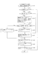
次に、図18のフローチャートを参照して、払出制御装置111内のMPU211により実行されるメイン処理を説明する。このメイン処理は、まず主制御装置110から出力される大当中信号SG3を受信したか否かを判定する大当中信号判定処理(S1001)が実行される。なお、大当中信号判定処理の詳細は、図19を参照して後述する。
Next, the main process executed by the
次に、主制御装置110から送信された賞球コマンドや払出復帰コマンド、払出初期化コマンドの種別を判定するコマンド判定処理を行い(S1002)、その後、コマンド判定処理で払出制御装置111が15個賞球払出コマンドを受信したと判定され、且つその15個賞球払出コマンドが異常な遊技状態の下で設定されたコマンドであると判定された場合に、賞球エラーを報知する賞球エラー報知処理(S1003)が実行される。
Next, command determination processing is performed to determine the type of prize ball command, payout return command, and payout initialization command transmitted from the main control device 110 (S1002), and then 15
なお、コマンド判定処理(S1002)の詳細については後述するが、該処理では、主制御装置110から送信された正常なコマンドを受信すると、払出許可フラグ213dがオンされ、賞球や貸出球の払い出しが許可される。また、払出許可フラグ213dが一旦オンされたとしても、払出制御装置111が受信した15個賞球払出コマンドが異常な遊技状態の下で設定されたコマンドであるとコマンド判定処理で判定されると、払出許可フラグ213dがオフされ、賞球や貸出球の払い出しが許可されなくなる。
Although details of the command determination process (S1002) will be described later, in this process, when a normal command transmitted from the
即ち、コマンド判定処理(S1002)の実行後、S1004の処理で、払出許可フラグ213dの状態が判別され(S1004)、払出許可フラグ213dがオンされていなければ(S1004:No)、未だ主制御装置110は立ち上がった状態にないか、或いは、払出制御装置111が受信した15個賞球払出コマンドが異常な遊技状態の下で設定されたコマンドであるとコマンド判定処理で判定されているので、かかる場合には、コマンド判定処理(S1002)において払出許可フラグ213dがオンされるまで、コマンド判定処理(S1002)を繰り返し実行する。特に、払出制御装置111が受信した15個賞球払出コマンドが異常な遊技状態の下で設定されたコマンドであるとコマンド判定処理で判定された場合には、正常な遊技状態の下で設定された15個賞球払出コマンドを主制御装置110から新たに受信するか、或いは、主制御装置110から1個賞球払出コマンド〜14個払出コマンドのいずれかを受信して、払出許可フラグ213dがオンされるまで、賞球エラー報知処理(S1003)が繰り返し実行される。このように、賞球エラー報知処理を繰り返し実行することで、払出制御装置111が受信した15個賞球払出コマンドが異常な遊技状態の下で設定されたコマンドであることを(不正が行われている可能性が高いことを)、遊技場の店員に容易に把握させることができる。なお、賞球エラー報知処理(S1003)の詳細については、図22を参照して後述する。
That is, after the execution of the command determination process (S1002), the state of the
S1004の処理において、払出許可フラグ213dがオンされていれば(S1004:Yes)、既に主制御装置110は立ち上がった状態にあり、主制御装置110から送信された15個賞球払出コマンドも正常な遊技状態の下で設定されたコマンドであるので、かかる場合には、状態復帰スイッチ120をチェックし、状態復帰動作開始と判定した場合に状態復帰動作を実行する(S1005)。
In the processing of S1004, if the
その後、下皿50の状態の変化に応じて下皿満タン状態又は下皿満タン解除状態の設定を実行する(S1006)。即ち、下皿満タンスイッチの検出信号により下皿50の満タン状態を判別し、下皿満タンになった時に、下皿満タン状態の設定を実行し、下皿満タンでなくなった時に、下皿満タン解除状態の設定を実行する。また、タンク球の状態の変化に応じてタンク球無し状態又はタンク球無し解除状態の設定を実行する(S1007)。即ち、タンク球無しスイッチの検出信号によりタンク球無し状態を判別し、タンク球無しになった時に、タンク球無し状態の設定を実行し、タンク球無しでなくなった時に、タンク球無し解除状態の設定を実行する。その後、報知する状態の有無を判別し、報知する状態が有る場合には、払出制御装置111に設けた7セグメントLED121により報知する(S1008)。なお、状態報知処理については、図24を参照して後述する。
Thereafter, the setting of the lower plate full state or the lower plate full state is performed according to the change in the state of the lower plate 50 (S1006). That is, when the
次に、S1009からS1011の各処理により、賞球払出の処理を実行する。即ち、賞球の払出不可状態でなく且つ、賞球数を記憶する総賞球個数メモリ213aの値が0でなければ(S1009:No,S1010:No)、賞球の払い出しを行うために賞球制御処理を開始する(S1011)。一方、賞球の払出不可状態(S1009:Yes)または総賞球個数メモリ213aの値が0であれば(S1010:Yes)、貸球払出の処理に移行する。
Next, prize ball payout processing is executed by each processing from S1009 to S1011. That is, if the prize ball is not paid out and the value of the total prize
S1012からS1014の貸球払出の処理では、貸球の払出不可状態でなく且つカードユニットからの貸球払出要求を受信していれば(S1012:No,S1013:Yes)、貸球を払い出すために貸球制御処理を開始する。一方、貸球の払出不可状態(S1012:Yes)または貸球払出要求を受信していない場合には(S1013:No)、処理をS1015へ移行する。また、貸球制御処理(S1014)の終了後も、同様に、処理をS1015へ移行する。 In the ball lending payout process from S1012 to S1014, if a lending payout request from the card unit is not received (S1012: No, S1013: Yes), the ball lending is paid out. The ball rental control process is started. On the other hand, when the rental ball cannot be dispensed (S1012: Yes) or when a rental ball dispensing request has not been received (S1013: No), the process proceeds to S1015. Similarly, after the ball rental control process (S1014) ends, the process proceeds to S1015.
S1015の処理では、球詰まり状態であることを条件にバイブレータ134の制御(バイブモータ制御)を実行する(S1015)。その後は、RAM213に電源断の発生情報が記憶されているか否かを判別し(S1016)、電源断の発生情報が記憶されていなければ(S1016:No)、停電監視回路252から停電信号SG1は出力されておらず、電源は遮断されていないので、かかる場合には、処理をS1001へ移行して、S1001からS1015のメイン処理を繰り返し実行する。 In the process of S1015, the control of the vibrator 134 (vibrating motor control) is executed on the condition that the ball is clogged (S1015). Thereafter, it is determined whether or not the occurrence information of power interruption is stored in the RAM 213 (S1016). If the occurrence information of power interruption is not stored (S1016: No), the power failure signal SG1 is received from the power failure monitoring circuit 252. Since it is not output and the power supply is not shut off, in such a case, the process proceeds to S1001, and the main process from S1001 to S1015 is repeatedly executed.
一方、S1016の処理において、電源断の発生情報が記憶されていれば(S1016:Yes)、停電の発生または電源のオフにより電源が遮断され、停電監視回路252から停電信号SG1が出力された結果、図16のNMI割込処理が実行されたということである。よって、かかる場合には、各割込処理の発生の禁止をし(S1017)、主制御装置110から送信されるコマンドの受信漏れを防止するために、再度、大当中信号判定処理(S1018)およびコマンド判定処理を実行する(S1019)。そして、RAM判定値を算出してRAM213に保存し(S1020)、RAM213のアクセスを禁止して(S1021)、電源が完全に遮断して処理が実行できなくなるまで無限ループを継続する。ここで、例えば、RAM判定値は、RAM213のバックアップされるスタックエリア及び作業エリアにおけるチェックサム値である。
On the other hand, in the processing of S1016, if the information on occurrence of power interruption is stored (S1016: Yes), the result of power failure being output due to the occurrence of a power failure or power off and the power failure monitoring circuit 252 outputting the power failure signal SG1. This means that the NMI interrupt process of FIG. 16 has been executed. Therefore, in such a case, the occurrence of each interrupt process is prohibited (S1017), and in order to prevent the reception of a command transmitted from the
なお、S1016の処理は、払出制御装置111のメイン処理の1サイクルが終わるタイミングで電源断の発生情報を確認しているので、電源遮断前の状態から復帰する場合には、処理を立ち上げ処理の終了後、S1001の処理から開始することができる。即ち、立ち上げ処理において初期化された場合と同様に、メイン処理を開始することができる。よって、電源遮断時の処理において、MPU211が使用している各レジスタの内容をスタックエリアへ退避したり、スタックポインタの値を保存しなくても、初期設定の処理(S901)において、スタックポインタを所定値(初期値)に設定することで、処理をS1001から開始することができる。従って、払出制御装置111の制御負担を軽減することができると共に、払出制御装置111が誤動作したり暴走することなく正確な制御を行うことができる。また、各処理が終わったタイミングで電源断の処理が実行されるので、RAM213にバックアップする情報量を少なくすることができる。
In the process of S1016, since the information on the occurrence of power interruption is confirmed at the timing when one cycle of the main process of the
次に、図19を参照して、払出制御装置111のメイン処理の中で実行される大当中信号判定処理について説明する。図19は、大当中信号判定処理を示したフローチャートである。大当中信号判定処理(S1001,S1018)は、主制御装置110から出力される大当中信号SG3を受信したか否かを判定する処理である。
Next, with reference to FIG. 19, the big hit signal determination process executed in the main process of the
大当中信号判定処理では、まず、主制御装置110から出力される大当中信号SG3を受信したか否か、即ち、大当中信号SG3はハイ状態か否かを判定する(S1101)。大当中信号SG3がハイ状態であれば(S1101:Yes)、大当中信号出力フラグ213fを、大当中信号SG3が受信されていることを示すオンにして(S1102)、この大当中信号判定処理を終了する。一方、大当中信号SG3がロウ状態であれば(S1101:No)、大当中信号出力フラグ213fを、大当中信号SG3が受信されていないことを示すオフにして(S1103)、この大当中信号判定処理を終了する。
In the big hit signal determination process, first, it is determined whether or not the big hit signal SG3 output from the
次に、図20を参照して、払出制御装置111のメイン処理の中で実行されるコマンド判定処理について説明する。図20は、コマンド判定処理を示したフローチャートである。コマンド判定処理は、受信したコマンドが正常なコマンドであるかを判定すると共に、正常なコマンドである場合には、そのコマンドに応じた処理を実行するものである。
Next, a command determination process executed in the main process of the
コマンド判定処理(S1002,S1018)では、まず、コマンド受信フラグ213eが、新たなコマンドを受信したことを示すオンであるか否かを判定する(S1201)。 In the command determination process (S1002, S1018), first, it is determined whether or not the command reception flag 213e is ON indicating that a new command has been received (S1201).
ここで、図25を参照して、コマンド受信フラグ213eの設定を行う外部割込み処理について説明する。図25は、払出制御装置111のMPU211で実行される外部割込み処理を示したフローチャートである。この外部割込み処理は、払出制御装置111が、主制御装置110からコマンドと共に送信されるストローブ信号を受信した場合に実行される。外部割込み処理が実行されると、主制御装置110から送信されたコマンドを受信すると共に、コマンド受信フラグ213eをオンにする(S1701)。その後、この外部割込み処理を終了する。なお、払出制御装置111で受信されたコマンドは、RAM213内の所定領域に記憶される。
Here, with reference to FIG. 25, the external interrupt processing for setting the command reception flag 213e will be described. FIG. 25 is a flowchart showing an external interrupt process executed by the
図20の説明に戻る。コマンド受信フラグ213eがオフであれば(S1201:No)、新たなコマンドを受信していないので、この処理を終了する。一方、コマンド受信フラグ213eがオンであれば(S1201:Yes)、その受信したコマンドは、1バイト目のデータか、2バイト目のデータかを判断する(S1202)。図7を参照して前述した通り、最上位ビットがセットされていれば1バイト目のデータであるので(S1202:Yes)、かかる場合には、上位コマンド記憶バッファ213bの値が0であるかを調べる(S1203)。
Returning to the description of FIG. If the command reception flag 213e is off (S1201: No), a new command has not been received, and this process is terminated. On the other hand, if the command reception flag 213e is on (S1201: Yes), it is determined whether the received command is the first byte data or the second byte data (S1202). As described above with reference to FIG. 7, if the most significant bit is set, it is the first byte data (S1202: Yes). In this case, is the value of the upper
コマンドを2バイト受信すると、上位コマンド記憶バッファ213bの値は0クリアされるので、正常であれば1バイト目のデータ受信時には、上位コマンド記憶バッファ213bの値は0となっている。よって、上位コマンド記憶バッファ213bの値が0でなければ(S1203:No)、何らかの異常が発生しているので、払出エラーフラグ213cをオンし(S1204)、処理をS1205へ移行する。一方、上位コマンド記憶バッファ213bの値が0であれば(S1203:Yes)、S1204の処理をスキップして、処理をS1205へ移行する。S1205の処理では、受信した1バイト目のデータを、上位コマンド記憶バッファ213bへ書き込んで、これを記憶する(S1205)。
When the command receives 2 bytes, the value of the upper
S1202の処理において、受信したコマンドが1バイト目のデータでなく、2バイト目のデータであれば(S1202:No)、受信したコマンドの読み込みが完了するので、コマンド受信フラグ213eをオフして(S1206)、受信したコマンドである2バイト目のデータと、S1205の処理で上位コマンド記憶バッファ213bに記憶した値とを、即ち1バイト目のデータとを加算する(S1207)。加算の結果がFFHであれば(S1208:Yes)、受信したコマンドは正常であるので、上位コマンド記憶バッファ213bの値がF0H以上であるかを調べる(S1209)。
In the processing of S1202, if the received command is not the first byte data but the second byte data (S1202: No), the command reception flag 213e is turned off because reading of the received command is completed ( In step S1206, the second byte data as the received command is added to the value stored in the upper
図7に示す通り、上位コマンド記憶バッファ213bの値がF0H以上であれば(S1209:Yes)、受信したコマンドは賞球コマンドであるので、かかる場合には、賞球払出個数設定処理を実行する(S1210)。一方、上位コマンド記憶バッファ213bの値がF0H以上でなければ(S1209:No)、受信したコマンドは、払出復帰コマンド又は払出初期化コマンドであるので、かかる場合には、状態設定処理を実行する(S1211)。賞球払出個数設定処理または状態設定処理の実行後は、処理をS1201へ移行し、前述した処理を繰り返す。なお、賞球払出個数設定処理または状態設定処理については後述する。
As shown in FIG. 7, if the value of the upper
S1208の処理において、1バイト目のデータと2バイト目のデータとの加算の結果がFFHでなければ(S1208:No)、何らかの異常が発生している。よって、かかる場合には、払出エラーフラグ213cをオンして(S1212)、コマンドエラーの発生を示すと共に、上位コマンド記憶バッファ213bの値を0クリアして(S1213)、受信した2バイトのコマンドを無効化する。これにより、異常なコマンドの受信による払出制御装置111の誤動作を防止することができる。S1213の処理後は、処理をS1201へ移行して、前述した処理を繰り返す。
In the process of S1208, if the result of the addition of the first byte data and the second byte data is not FFH (S1208: No), some abnormality has occurred. Therefore, in such a case, the
次に、図21を参照して、コマンド判定処理の中で実行される賞球払出個数設定処理(S1210)について説明する。図21は、賞球払出個数設定処理(S1210)を示したフローチャートである。賞球払出個数設定処理では、受信した賞球コマンドが正常であれば、総賞球個数メモリ213aの値を更新する。
Next, with reference to FIG. 21, the winning ball payout number setting process (S1210) executed in the command determination process will be described. FIG. 21 is a flowchart showing the prize ball payout number setting process (S1210). In the winning ball payout number setting process, if the received winning ball command is normal, the value of the total winning
賞球払出個数設定処理(S1210)では、まず、受信した賞球コマンドの賞球数が1以上15以下であるかを調べ(S1301)、それ以外であれば(S1301:No)、誤った賞球コマンドを受信したことになる(図7参照)。よって、かかる場合には、受信したコマンドを無効化して、この処理を終了する。 In the prize ball payout number setting process (S1210), first, it is checked whether the number of prize balls of the received prize ball command is 1 or more and 15 or less (S1301). Otherwise (S1301: No), an incorrect prize is awarded. A ball command is received (see FIG. 7). Therefore, in such a case, the received command is invalidated and this process is terminated.
一方、受信した賞球コマンドの賞球数が1以上15以下であれば(S1301:Yes)、受信した賞球コマンドの賞球数が15であるか否か、即ち、受信したコマンドが15個賞球払出コマンドであるか否かを判定する(S1302)。賞球数が15であれば、即ち、受信したコマンドが15個賞球払出コマンドであれば(S1302:Yes)、大当中信号出力フラグ213fは、払出制御装置111が大当中信号SG3を受信していることを示すオンであるか否かを判定する(S1303)。
On the other hand, if the number of prize balls of the received prize ball command is 1 or more and 15 or less (S1301: Yes), whether or not the number of prize balls of the received prize ball command is 15, that is, 15 received commands. It is determined whether the command is a prize ball payout command (S1302). If the number of winning balls is 15, that is, if the received command is 15 winning ball payout commands (S1302: Yes), the
ここで、受信したコマンドが15個賞球払出コマンドであれば、大当中信号出力フラグ213fが大当中信号SG3を受信していることを示すオンであるかを判定する理由について説明する。これは、受信したコマンドが15個賞球払出コマンドであれば、特定入賞口65aに球が入賞したことを示しているが、このとき、遊技が正常な状態であれば、大当たり演出中であり払出制御装置111は大当中信号SG3を受信しているはずであるので、これを確認するためである。よって、S1303の処理では、受信したコマンドが15個賞球払出コマンドである場合に、大当中信号出力フラグ213fがオンであれば、払出制御装置111により大当中信号SG3が受信されているので、払出制御装置111が受信した15個賞球払出コマンドは正常な遊技状態の下で設定されたコマンドであると判定する。一方、S1303の処理では、受信したコマンドが15個賞球払出コマンドである場合に、大当中信号出力フラグ213fがオフであれば、払出制御装置111により大当中信号SG3が受信されていないので、払出制御装置111が受信した15個賞球払出コマンドは異常な遊技状態の下で設定されたコマンドであると判定する。
Here, if the received command is 15 prize ball payout commands, the reason why it is determined whether or not the big hit
図21の説明に戻る。大当中信号出力フラグ213fがオンであれば(S1303:Yes)、払出制御装置111が受信した15個賞球払出コマンドは正常な遊技状態の下で設定されたコマンドであるので、大当中賞球エラーフラグ213gをオフして(S1304)、賞球コマンドで指示される賞球数を総賞球個数メモリ213aへ加算する(S1305)。なお、S1302の処理で、賞球コマンドで指示される賞球数が15でない場合には、即ち、受信したコマンドが15個賞球払出コマンドでない場合には(S1302:No)、S1303およびS1304の処理をスキップして、S1305の処理が実行される。加算された個数の賞球は、前述した賞球制御処理(S1011)によって払い出される。S1305の処理後、払出許可フラグ213dをオンして(S1306)、賞球の払い出しを許可すると共に、上位コマンド記憶バッファ213bの値を0クリアして(S1307)、次のコマンドの受信に備える。更に、払出エラーフラグ213cをオフして(S1308)、この処理を終了する。
Returning to the description of FIG. If the big hit
一方、S1303の処理で、大当中信号出力フラグ213fがオフであれば(S1303:No)、払出制御装置111が大当中信号SG3を受信していないにも拘らず、特定入賞口65aに球が入賞したことを示す15個賞球払出コマンドを受信しているので、払出制御装置111が受信した15個賞球払出コマンドは異常な遊技状態の下で設定されたコマンドであると判定し、大当中賞球エラーフラグ213gをオンする(S1309)。その後、払出許可フラグ213dをオフして(S1310)、賞球の払い出しを不許可状態にし、S1307の処理へ移行する。このS1310の処理により、受信した15個賞球払出コマンドを無効化して、異常な遊技状態の下で設定された15個賞球払出コマンドによる払出制御装置111の不正動作を防止することができる。
On the other hand, if the big hit
上述した通り、賞球払出個数設定処理では、受信したコマンドが15個賞球払出コマンドである場合に、大当中信号出力フラグ213fがオンであれば、即ち、払出制御装置111が大当中信号SG3を受信していれば、払出制御装置111が受信した15個賞球払出コマンドは正常な遊技状態の下で設定されたコマンドであると判定し、大当中賞球エラーフラグ213gをオフして、総賞球個数メモリ213aの値を更新する。一方、受信したコマンドが15個賞球払出コマンドである場合に、大当中信号出力フラグ213fがオフであれば、即ち、払出制御装置111が大当中信号SG3を受信していなければ、払出制御装置111が受信した15個賞球払出コマンドは異常な遊技状態の下で設定されたコマンドであると判定して、大当中賞球エラーフラグ213gをオンする一方、払出許可フラグ213dをオフする。更に、総賞球個数メモリ213aの値を更新しない。よって、異常な遊技状態の下(不正が行われている可能性が高い状況の下で)で設定された15個賞球払出コマンドに基づいて、払出制御装置111による賞球の払い出しが行われることを防止することができる。
As described above, in the award ball payout number setting process, when the received command is 15 award ball payout commands, if the big hit
なお、大当中賞球エラーフラグ213gがオンとなっても、15個賞球払出コマンドを新たに受信し、S1303の処理で、大当中信号出力フラグ213fがオンであると判定されると、大当中賞球エラーフラグ213gはオフに設定される。よって、例えば、ラッチ回路272の誤作動等により、主制御装置110から大当中信号SG3が正しく送信されない場合に、払出制御装置111が15個賞球払出コマンドを受信して、大当中賞球エラーフラグ213gが一時的にオンになったとしても、その後、主制御装置110から大当中信号SG3が正しく送信されている間に、払出制御装置111が15個賞球払出コマンドを新たに受信した場合には、大当中賞球エラーフラグ213gをオフして、遊技を正常に続行することができる。
Even if the big hit prize
また、1個賞球払出コマンド〜14個賞球払出コマンドのいずれかを受信した場合には、払出エラーフラグ213cをオフするので、例えば、ラッチ回路272の誤作動等により、主制御装置110から大当中信号SG3が正しく送信されない場合に、払出制御装置111が15個賞球払出コマンドを受信して、払出エラーフラグ213cがオンになったとしても、1個賞球払出コマンド〜14個賞球払出コマンドを新たに受信することにより、賞球の払い出しの不許可を解除することができる。この間に、主制御装置110から大当中信号SG3が正しく送信開始されれば、払出制御装置111が15個賞球払出コマンドを受信しても、遊技を正常に続行することができる。
In addition, when any one of the 1-ball prize payout command to the 14-ball prize ball payout command is received, the
次に、図22を参照して、コマンド判定処理の中で実行される賞球エラー報知処理(S1003)について説明する。図22は、賞球エラー報知処理(S1003)を示したフローチャートである。賞球エラー報知処理では、まず、大当中賞球エラーフラグ213gがオンであるか否かが判定される(S1401)。大当中賞球エラーフラグ213gがオンであれば(S1401:Yes)、S1303の処理で(図21参照)、払出制御装置111が受信した15個賞球払出コマンドは異常な遊技状態の下で設定されたコマンドであると判定されているので、賞球エラーの発生を7セグメントLED121で報知する(S1402)。この報知では、例えば、7セグメントLED121により「S」の文字を表示して、賞球エラーの発生を報知する。その後、賞球エラーの発生をホールコンピュータ262へ出力する(S1403)。S1403の処理後、この賞球エラー報知処理を終了する。
Next, with reference to FIG. 22, the prize ball error notification process (S1003) executed in the command determination process will be described. FIG. 22 is a flowchart showing the prize ball error notification process (S1003). In the prize ball error notification process, first, it is determined whether or not the big hit prize
一方、大当中賞球エラーフラグ213gがオフであれば(S1401:No)、S1303の処理で(図21参照)、払出制御装置111が受信した15個賞球払出コマンドは正常な遊技状態の下で設定されたコマンドであると判定されているので、S1402の処理をスキップして、この賞球エラー報知処理を終了する。
On the other hand, if the big hit prize
次に、図23を参照して、コマンド判定処理の中で実行される状態設定処理(S1211)について説明する。図23は、状態設定処理(S1211)を示したフローチャートである。状態設定処理では、払出復帰コマンドまたは払出初期化コマンドに応じた処理が実行される。 Next, the state setting process (S1211) executed in the command determination process will be described with reference to FIG. FIG. 23 is a flowchart showing the state setting process (S1211). In the state setting process, a process according to the payout return command or the payout initialization command is executed.
受信したコマンドが払出復帰コマンドであれば(S1501:Yes)、処理をS1506へ移行する。そして、払出許可フラグ213dをオンして(S1506)、賞球の払い出しを許可し、上位コマンド記憶バッファ213bの値を0クリアして(S1507)、次のコマンドの受信に備え、更に、払出エラーフラグ213cをオフして(S1508)、この処理を終了する。
If the received command is a payout return command (S1501: Yes), the process proceeds to S1506. Then, the
受信したコマンドが払出初期化コマンドであれば(S1501:No、S1502:Yes)、払出許可フラグ213dの状態を調べる(S1503)。払出許可フラグ213dがオフであれば(S1503:No)、払出初期化コマンドの正常な受信であるので、かかる場合には、RAM213の作業領域を0クリアし(S1504)、その作業領域に初期化時の初期値を設定して(S1505)、RAM213の作業領域の初期化を実行する。
If the received command is a payout initialization command (S1501: No, S1502: Yes), the state of the
その後は、払出復帰コマンドの受信時と同様に、払出許可フラグ213dをオンして(S1506)、賞球の払い出しを許可し、上位コマンド記憶バッファ213bの値を0クリアして(S1507)、次のコマンドの受信に備え、更に、払出エラーフラグ213cをオフして(S1508)、この処理を終了する。
Thereafter, as in the case of receiving the payout return command, the
受信したコマンドが払出初期化コマンドであっても(S1501:No、S1502:Yes)、払出許可フラグ213dがオンされていれば(S1503:Yes)、既に、図7に示す、いずれかの正常なコマンドを受信して、賞球の払出制御は可能な状態になっている。よって、かかる場合には、RAM213の作業領域の初期化を回避するべく、S1504からS1506の処理をスキップして、処理をS1507へ移行する。その後は、上位コマンド記憶バッファ213bの値を0クリアして(S1507)、次のコマンドの受信に備え、払出エラーフラグ213cをオフして(S1508)、この処理を終了する。
Even if the received command is a payout initialization command (S1501: No, S1502: Yes), if the
なお、受信したコマンドが払出復帰コマンドでも無く(S1501:No)、払出初期化コマンドでもなければ(S1502:No)、誤った賞球コマンドを受信したことになるので(図7参照)、かかる場合には、受信したコマンドを無効化して、この処理を終了する。 If the received command is neither a payout return command (S1501: No) nor a payout initialization command (S1502: No), it means that an incorrect prize ball command has been received (see FIG. 7). In this case, the received command is invalidated and this process is terminated.
図24は、メイン処理の中で実行される状態報知処理(S1008)を示したフローチャートである。状態報知処理では、まず、払出エラーフラグ213cの状態を確認し(S1601)、オンされていれば(S1601:Yes)、7セグメントLED121に「C」の文字を表示して、コマンドエラーの発生を報知する(S1602)。一方、払出エラーフラグ213cがオンされていない場合(S1602:No)、或いは、S1602の処理後は、下皿50の満タン状態やタンクの球の貯留状態など、その他の払出制御装置111の状態を報知し(S1603)、この処理を終了する。
FIG. 24 is a flowchart showing a state notification process (S1008) executed in the main process. In the status notification process, first, the status of the
以上説明したとおり、本実施形態のパチンコ機10によれば、払出制御装置111は、特定入賞口65aに球が入賞したことを示す15個賞球払出コマンドを受信した場合に、大当中信号SG3を受信していれば(大当中信号出力213fがオンであれば)、15個の賞球の払い出しを行うように構成されている。よって、払出制御装置111が、15個賞球払出コマンドを受信した場合に、大当中信号SG3を受信していなければ(大当中信号出力213fがオフであれば)、払出制御装置111は、受信した15個賞球払出コマンドは異常な遊技状態の下で設定されたコマンドであると判定し、15個賞球払出コマンドによる賞球の払い出しを行わない。従って、異常な遊技状態の下(不正が行われている可能性が高い状況の下で)で設定された15個賞球払出コマンドに基づいて、払出制御装置111による賞球の払い出しが行われることを防止することができる。
As described above, according to the
また、本実施形態のパチンコ機10によれば、特に、15個賞球払出コマンドを払出制御装置111が受信した場合に、払出制御装置111が大当中信号SG3の受信の有無を判定するように構成している。これは、大当たりが発生し、特定入賞口65aに球が入賞した場合には、その入賞により払い出される賞球数は、通常、払出制御装置111によって一度に払い出すことができる限界値である最大値に設定されるからである(本実施形態では15個に設定)。ここで、本パチンコ機10では、払出制御装置111に最大値の賞球を払い出させる15個賞球払出コマンドが受信された場合に、大当中信号SG3の受信の有無を判定して、払出制御装置111の払い出しを実行させているので、何らかの不正行為が行われて、払出制御装置111から不正に球が払い出されたとしても、払出制御装置111から一度に15個ずつ球が払い出されることはない。よって、何らかの不正により払出制御装置111から球が払い出されたとしても、一度に払い出される球の数を最大値未満(15個未満)とすることで、不正行為による被害を低減することができる。
Further, according to the
また、本実施形態のパチンコ機10によれば、大当中信号SG3を出力する処理である大当中信号出力処理(図10のS206)を、主制御装置110の4ms周期の定期処理内で実行している。しかし、主制御装置110は、ラッチ回路272を用いて、大当中信号SG3を払出制御装置111へ送信しているので、大当中信号出力処理が4ms周期で実行されても、主制御装置110は、4ms周期で定期的に大当中信号SG3を払出制御装置111へ送信することはない。従って、例えば不正行為者によって大当中信号SG3の送信タイミングが検出されたとしても、主制御装置110で行われる定期処理の周期を容易に把握することができない。つまり、主制御装置110で行われる定期処理の周期を不正行為者に把握困難にすることができるのである。
Further, according to the
また、主制御装置110から払出制御装置111へ出力されるコマンドを2バイトで構成し、これらを1バイトずつ加算または排他的論理和した場合に、演算後の最下位1バイトがFFHとなるようにしている。よって、払出制御装置111では、入力した2バイトのコマンドを1バイトずつ加算または排他的論理和し、その結果がFFHでなければ、該コマンドは正常なコマンドでないと判断して、該コマンドの入力を無効化すると共に、払出制御装置111に設けられた7セグメントLED121に「C」の文字を表示して、コマンドエラーを報知する。よって、払出制御装置111は、正常なコマンドだけを有効なコマンドとして入力することができるので、遊技の払出制御を正常に行って、規定外の払い出しや、不正行為による払い出しを防止することができる。
Further, when the command output from the
また、正常でないコマンドを入力した場合には、7セグメントLED121により、その旨(コマンドエラーの発生)を報知するので、パチンコ機10に断線などが生じた場合、或いはパチンコ機10に不正行為が行われた場合には、これらをいち早く察知して対処することができる。更に、コマンドエラーの報知中に、正常なコマンドを入力した場合には、コマンドエラーの報知を終了する。よって、ノイズなどの影響によって、異常なコマンドを一時的に入力した場合にも、正常なコマンドを入力することにより、該報知を解除して、遊技を正常に続行させることができる。
In addition, when a command that is not normal is input, the 7-
また、払出制御装置111の立ち上げ時に、必ず主制御装置110から出力される払出復帰コマンドと払出初期化コマンドとを使用して、これらのコマンドを送信する信号線や、その信号線を接続するコネクタ207,217にショート(半田ブリッジ)があるか否かを検出できるようにしている。よって、かかる異常の無い状態で遊技を実行できるので、主制御装置110から周辺制御装置111へ正常にコマンドを出力して、賞球の払出制御を正常に行わせることができる。
In addition, when the
パチンコ機10の出荷前に生産工場で行われる検査において、パチンコ機10の電源オンと、RAMの内容を初期化した後の電源オンとをするだけで、断線やショートをチェックすることができる。よって、検査のために、わざわざ前面枠14を開けて、一般入賞口63や第1入球口(始動口)64へ球を入れるなどの作業が不要となり、検査工程を効率化することができる。
In an inspection performed at a production factory before shipment of the
次に、図26および図27を参照して、第2実施形態のパチンコ機について説明する。図26は、第2実施形態のパチンコ機の大当中信号判定処理を示すフローチャートである。図26に示す大当中信号判定処理は、図19に示す大当中信号判定処理の処理内容を変更したものである。具体的には、図19に示す大当中信号判定処理で使用した大当中信号出力フラグ213fに代えて、図26に示す大当中信号判定処理では、賞球数検証メモリ213h(図示せず)を用いて処理を行っている。よって、図26に示す大当中信号判定処理では、図19に示す大当中信号判定処理と同一の部分には同一の番号を付してその説明は省略し、異なる部分についてのみ説明する。
Next, a pachinko machine according to a second embodiment will be described with reference to FIGS. FIG. 26 is a flowchart showing the big hit signal determination process of the pachinko machine according to the second embodiment. The big hit signal determination processing shown in FIG. 26 is obtained by changing the processing contents of the big hit signal determination processing shown in FIG. Specifically, instead of the big shot
図26に示す大当中信号判定処理では、S1101の処理により、大当中信号SG3が受信されていると判定された場合、即ち、大当中信号SG3がハイ状態であると判定された場合には(S1101:Yes)、払出制御装置111のRAM213内に設けられた賞球数検証メモリ213h(図示せず)に、大当中信号SG3が受信されていることを示す0FHを設定して(S1104)、この処理を終了する。一方、S1101の処理により、大当中信号SG3が受信されていないと判定された場合には(S1101:No)、賞球数検証メモリ213hに、大当中信号SG3が受信されていないことを示す00Hを設定して(S1105)、この処理を終了する。
In the big hit signal determination process shown in FIG. 26, when it is determined by the processing of S1101 that the big hit signal SG3 is received, that is, when the big hit signal SG3 is determined to be in the high state ( S1101: Yes), 0FH is set in the winning ball number verification memory 213h (not shown) provided in the
次に、図27を参照して、第2実施形態のパチンコ機の賞球払出個数設定処理について説明する。図27は、第2実施形態のパチンコ機の賞球払出個数設定処理を示すフローチャートである。図27に示す賞球払出個数設定処理は、図21に示す賞球払出個数設定処理の処理内容を変更したものである。具体的には、図21に示す賞球払出個数設定処理では、大当中信号出力フラグ213fを用いて15個賞球払出コマンドが正常な遊技状態の下で設定されたか否かを判定したのに対して、図27に示す賞球払出個数設定処理では、賞球数検証メモリ213hに記憶された値を用いて15個賞球払出コマンドが正常な遊技状態の下で設定されたか否かを判定している。よって、図27に示す賞球払出個数設定処理では、図21に示す賞球払出個数設定処理と同一の部分には同一の番号を付してその説明は省略し、異なる部分についてのみ説明する。
Next, with reference to FIG. 27, the winning ball payout number setting process of the pachinko machine according to the second embodiment will be described. FIG. 27 is a flowchart showing a prize ball payout number setting process of the pachinko machine according to the second embodiment. The prize ball payout number setting process shown in FIG. 27 is obtained by changing the content of the prize ball payout number setting process shown in FIG. Specifically, in the prize ball payout number setting process shown in FIG. 21, it is determined whether or not the 15 prize ball payout command is set under a normal gaming state by using the big hit
図27に示す賞球払出個数設定処理では、S1302の処理で、賞球数が15を示していれば、即ち、受信したコマンドが15個賞球払出コマンドを示していれば(S1302:Yes)、賞球数、つまり、受信した15個賞球払出コマンドの2バイト目の値と(0FH、図7参照)、賞球数検証メモリ213h(図示せず)に記憶された値との論理積を算出する(S1312)。 In the prize ball payout number setting process shown in FIG. 27, if the prize ball number indicates 15 in the process of S1302, that is, if the received command indicates 15 prize ball payout commands (S1302: Yes). The logical product of the number of winning balls, that is, the value of the second byte of the received 15 winning ball payout command (0FH, see FIG. 7) and the value stored in the winning ball number verification memory 213h (not shown). Is calculated (S1312).
算出した論理積が0FHであれば(S1313:Yes)、賞球数検証メモリ213h(図示せず)には0FHが記憶されていることとなり、大当中信号SG3が払出制御装置111で受信されていることを示している(図26のS1104参照)。よって、払出制御装置111が受信した15個賞球払出コマンドは正常な遊技状態の下で設定されたコマンドであると判定され、大当中賞球エラーフラグをオフして(S1304)、賞球数である15(0FH)を総賞球個数メモリ213aに加算する(S1305)。その後、S1306以降の処理へ移行する。
If the calculated logical product is 0FH (S1313: Yes), 0FH is stored in the award ball number verification memory 213h (not shown), and the payout control signal SG3 is received by the
一方、算出した論理積(賞球数)が0FHでなければ(S1313:No)、賞球数検証メモリ213h(図示せず)には00Hが記憶されていることとなり、大当中信号SG3が払出制御装置111で受信されていないことを示している(図26のS1105参照)。よって、払出制御装置111が受信した15個賞球払出コマンドは異常な遊技状態の下で(不正が行われている可能性が高い状態の下で)設定されたコマンドであると判定されて、大当中賞球エラーフラグがオンされる(S1309)。その後、S1305の処理をスキップして、総賞球個数メモリ213aに賞球数を加算せずに、S1306の処理に移行する。
On the other hand, if the calculated logical product (number of winning balls) is not 0FH (S1313: No), 00H is stored in the winning ball number verification memory 213h (not shown), and the big hit signal SG3 is paid out. This indicates that the information has not been received by the control device 111 (see S1105 in FIG. 26). Therefore, it is determined that the 15 prize ball payout command received by the
上述した通り、賞球払出個数設定処理では、受信した15個賞球払出コマンドの2バイト目の値と(0FH、図7参照)、賞球数検証メモリ213h(図示せず)に記憶された値との論理積を算出することで、払出制御装置111が受信した15個賞球払出コマンドが、正常な遊技状態の下で設定されたものであるか、異常な遊技状態の下で設定されたものであるかを判定することができる。
As described above, in the winning ball payout number setting process, the value of the second byte of the received 15 winning ball payout command (0FH, see FIG. 7) and the number of winning ball verification memory 213h (not shown) are stored. By calculating the logical product with the value, the 15 prize ball payout command received by the
最後に、図28を参照して、第3実施形態のパチンコ機について説明する。図28は、第3実施形態のパチンコ機の電気的構成を示したブロック図である。図28に示す第3実施形態のパチンコ機は、図4に示す第1実施形態のパチンコ機の電気的構成を一部変更したものである。よって、図28に示す第3実施形態のパチンコ機のブロック図では、図4に示す第1実施形態のパチンコ機のブロック図と同一の部分には同一の番号を付してその説明は省略し、異なる部分についてのみ説明する。 Finally, a pachinko machine according to a third embodiment will be described with reference to FIG. FIG. 28 is a block diagram showing an electrical configuration of the pachinko machine according to the third embodiment. The pachinko machine of the third embodiment shown in FIG. 28 is obtained by partially changing the electrical configuration of the pachinko machine of the first embodiment shown in FIG. Therefore, in the block diagram of the pachinko machine of the third embodiment shown in FIG. 28, the same parts as those in the block diagram of the pachinko machine of the first embodiment shown in FIG. Only different parts will be described.
図28に示す第3実施形態のパチンコ機では、図4に示す主制御装置110に設けられたコネクタ274を削除している。そして、図28に示す第3実施形態のパチンコ機では、払出制御装置111に新たにコネクタ276を設け、払出制御装置111のコネクタ275と入出力ポート215との間に、新たに設けたコネクタ276を接続している。このコネクタ276に外部出力端子板281を接続することで、主制御装置110から大当中信号SG3が出力された場合には、このコネクタ276を介して、外部出力端子板281からホールコンピュータ262へ大当中信号SG3を出力することができる。
In the pachinko machine according to the third embodiment shown in FIG. 28, the connector 274 provided in the
このように、コネクタ275と入出力ポート215との間に、外部出力端子板281へ大当中信号SG3を出力するコネクタ276を接続することで、例えば、コネクタ273とコネクタ275を接続する信号線に、大当中信号SG3を常時出力する不正基板が接続された場合には、ホールコンピュータ262へ大当中信号SG3が常時出力されることとなる。よって、ホールコンピュータ262で大当中信号SG3の入力状況を確認すれば、大当中信号SG3が常時出力されていることを検出することができる。これにより、例えば、コネクタ273とコネクタ275とを接続する信号線に接続された不正基板を発見することができる。
In this way, by connecting the
また、コネクタ275と入出力ポート215との間にコネクタ276を接続することにより、大当中信号SG3と入出力ポート215から出力される信号とで外部出力端子板281を共用することができるので、第1実施形態のパチンコ機10に設けられていた外部出力端子板261を不要にすることができる。
Also, by connecting the
以上、各実施の形態に基づき本発明を説明したが、本発明は上記形態に何ら限定されるものではなく、本発明の趣旨を逸脱しない範囲内で種々の変形改良が可能であることは容易に推察できるものである。 As described above, the present invention has been described based on each embodiment, but the present invention is not limited to the above-described embodiment, and various modifications can be easily made without departing from the gist of the present invention. Can be inferred.
各実施形態では、特定入賞口65aに球が入賞して、払出制御装置111が15個賞球払出コマンドを受信した場合に、大当中信号SG3を受信していなければ(大当中信号出力213fがオフであれば)、払出制御装置111が受信した15個賞球払出コマンドは異常な遊技状態の下で設定されたコマンドであると判定し、15個賞球払出コマンドによる賞球の払い出しが払出制御装置111で行われないように構成したが、これに限られるものではない。即ち、球が入賞した場合に所定数の賞球が払出制御装置111から払い出される入賞口と、その入賞口への球の入賞路(流路)を所定条件の成立に基づいて開閉する入賞口の両端に設けられた一対の開放片(一対の開放翼)から構成される所謂電動チューリップに第1実施形態から第3実施形態に示す発明を適用しても良い。このときには、一対の開放片が開放され、電動チューリップの入賞口に球が入賞した場合に、主制御装置110から払出制御装置111へ所定時間、入賞信号を出力する。そして、払出制御装置111が入賞口への入賞に基づく賞球コマンドを受信した場合に、入賞信号を受信していれば、払出制御装置111は賞球コマンドに基づく賞球を払い出す一方、払出制御装置111が入賞口への入賞に基づく賞球コマンドを受信した場合に、入賞信号を受信していなければ、払出制御装置111は賞球コマンドに基づく賞球を払い出さないように構成すれば良い。このように構成することで、一対の開放片が不正に開放され、入賞口へ不正に球が入賞した場合に、払出制御装置111による賞球の払い出しが行われることを防止することができる。
In each embodiment, when a ball wins the specific winning
また、球が入賞することによって一対の可動部材を所定駆動させ得る役物開放口と、その役物開放口に球が入賞して一対の可動部材が駆動し、その後、球が入賞することで遊技者に大当たりを付与するV入賞口とから構成される役物可変入賞装置に第1実施形態から第3実施形態に示す発明を適用しても良い。このときには、V入賞口に球が入賞した場合に、主制御装置110から払出制御装置111へ大当たりが付与されている間、大当たり信号を出力する。そして、払出制御装置111がV入賞口への入賞に基づく賞球コマンドを受信した場合に、大当たり信号を受信していれば、払出制御装置111は賞球コマンドに基づく賞球を払い出す一方、払出制御装置111がV入賞口への入賞に基づく賞球コマンドを受信した場合に、大当たり信号を受信していなければ、払出制御装置111は賞球コマンドに基づく賞球を払い出さないように構成すれば良い。このように構成することで、一対の可動部材が不正に駆動され、V入賞口へ不正に球が入賞した場合に、払出制御装置111による賞球の払い出しが行われることを防止することができる。
In addition, an accessory opening that allows a pair of movable members to be driven in a predetermined manner by winning a ball, and a ball is awarded to the accessory opening and the pair of movable members are driven. The invention shown in the first embodiment to the third embodiment may be applied to an accessory variable winning device constituted by a V winning opening for giving a jackpot to a player. At this time, when a ball is won in the V winning opening, a big hit signal is output while the big hit is given from the
また、各実施形態では、特定入賞口65aに球が入賞して、払出制御装置111が15個賞球払出コマンドを受信した場合に、大当中信号SG3を受信していなければ(大当中信号出力213fがオフであれば)、払出制御装置111が受信した15個賞球払出コマンドは異常な遊技状態の下で設定されたコマンドであると判定し、15個賞球払出コマンドによる賞球の払い出しが払出制御装置111で行われないように構成したが、これに限られるものではない。例えば、音声ランプ制御装置113へ不正な細工が行われ、音声出力装置226から不正な音が出力されないように第1実施形態から第3実施形態に示す発明を適用しても良い。この場合には、例えば、大当たりが発生した場合に、主制御装置110から音声ランプ制御装置113へ大当中信号SG3を出力する。そして、音声ランプ制御装置113が大当たり演出を実行させるコマンドを受信した場合に、音声ランプ制御装置113が大当中信号SG3を受信していれば、大当たり演出に伴う音を出力する一方、音声ランプ制御装置113が大当たり演出を実行させるコマンドを受信した場合に、音声ランプ制御装置113が大当中信号SG3を受信していなければ、大当たり演出に伴う音を出力しないように構成すれば良い。
In each embodiment, when a ball is won in the specific winning
同様に、例えば、表示制御装置114へ不正な細工が行われ、第3図柄表示装置81により不正な表示が実行されないように第1実施形態から第3実施形態に示す発明を適用しても良い。この場合には、例えば、大当たりが発生した場合に、主制御装置110から音声ランプ制御装置113を介して表示制御装置114へ大当中信号SG3を出力する。そして、表示制御装置114が大当たり演出を実行させるコマンドを受信した場合に、表示制御装置114が大当中信号SG3を受信していれば、大当たり演出に伴う表示を実行する一方、表示制御装置114が大当たり演出を実行させるコマンドを受信した場合に、表示制御装置114が大当中信号SG3を受信していなければ、大当たり演出に伴う表示を実行しないように構成すれば良い。
Similarly, for example, the invention shown in the first to third embodiments may be applied so that unauthorized display is performed on the
また、各実施形態では、特定入賞口65aに球が入賞して、払出制御装置111が15個賞球払出コマンドを受信した場合に、大当中信号SG3を受信していなければ(大当中信号出力213fがオフであれば)、払出制御装置111が受信した15個賞球払出コマンドは異常な遊技状態の下で設定されたコマンドであると判定し、15個賞球払出コマンドによる賞球の払い出しが払出制御装置111で行われないように構成したが、これに限られるものではない。第1実施形態から第3実施形態に示す発明を例えば、払出制御装置111が1個賞球払出コマンド〜14個賞球払出コマンドのいずれかのコマンドを受信した場合に適用しても良い。この場合には、例えば、入賞口63や入賞口64に球が入賞した場合に、主制御装置110から払出制御装置111へ所定時間、入賞信号を出力する。そして、払出制御装置111が入賞口63や入賞口64への入賞に基づく賞球コマンドを受信した場合に、入賞信号を受信していれば、払出制御装置111は賞球コマンドに基づく賞球を払い出す一方、払出制御装置111が入賞口63や入賞口64への入賞に基づく賞球コマンドを受信した場合に、入賞信号を受信していなければ、払出制御装置111は賞球コマンドに基づく賞球を払い出さないように構成すれば良い。このように構成することで、入賞口63や入賞口64へ不正に球が入賞した場合に、払出制御装置111による賞球の払い出しが行われることを防止することができる。
In each embodiment, when a ball is won in the specific winning
また、各実施形態では、ドライバIC270と、ドライバIC271と、ラッチ回路272とを主制御装置110のMPU201とは別体に構成したが、これに限られるものではなく、ドライバIC270と、ドライバIC271と、ラッチ回路272とをMPU201に内蔵しても良い。この場合には、ドライバIC270と、ドライバIC271と、ラッチ回路272とを備えた1チップMPUとして、MPU201を構成することができる。
In each embodiment, the driver IC 270, the
また、各実施形態では、パチンコ機毎にホールコンピュータ262を設けたが、これに限られるものではなく、各パチンコ機から出力される情報を1のホールコンピュータ262で受信しても良い。
In each embodiment, the
本発明を上記実施形態とは異なるタイプのパチンコ機等に実施しても良い。例えば、一度大当たりすると、それを含めて複数回(例えば2回、3回)大当たり状態が発生するまで、大当たり期待値が高められるようなパチンコ機(通称、2回権利物、3回権利物と称される)として実施しても良い。また、パチンコ機以外にも、アレパチ、雀球、スロットマシン、いわゆるパチンコ機とスロットマシンとが融合した遊技機などの各種遊技機として実施するようにしても良い。 You may implement this invention in the pachinko machine etc. of a type different from the said embodiment. For example, once a big hit, a pachinko machine that raises the expected value of the big hit until a big hit state occurs (for example, two times or three times) including that (for example, a two-time right item, a three-time right item) May also be implemented. In addition to the pachinko machines, various game machines such as an alepacchi, a sparrow ball, a slot machine, a game machine in which a so-called pachinko machine and a slot machine are integrated may be used.
なお、スロットマシンは、例えばコインを投入して図柄有効ラインを決定させた状態で操作レバーを操作することにより図柄が変動され、ストップボタンを操作することにより図柄が停止されて確定される周知のものである。従って、スロットマシンの基本概念としては、「複数の識別情報からなる識別情報列を変動表示した後に識別情報を確定表示する表示装置を備え、始動用操作手段(例えば操作レバー)の操作に起因して識別情報の変動表示が開始され、停止用操作手段(例えばストップボタン)の操作に起因して、或いは、所定時間経過することにより、識別情報の変動表示が停止して確定表示され、その停止時の識別情報の組合せが特定のものであることを必要条件として、遊技者に所定の遊技価値を付与する特別遊技を発生させるスロットマシン」となり、この場合、遊技媒体はコイン、メダル等が代表例として挙げられる。 In the slot machine, for example, a symbol is changed by operating a control lever in a state where a symbol effective line is determined by inserting coins, and a symbol is stopped and confirmed by operating a stop button. Is. Accordingly, the basic concept of the slot machine is that it is provided with a display device for confirming and displaying the identification information after variably displaying the identification information string composed of a plurality of identification information, and resulting from the operation of the starting operation means (for example, the operation lever). The variation display of the identification information is started, and the variation display of the identification information is stopped and fixedly displayed due to the operation of the operation means for stop (for example, the stop button) or when a predetermined time elapses. It is a slot machine that generates a special game that gives a player a predetermined game value on the condition that the combination of identification information at the time is a specific condition. In this case, the game medium is typically a coin, medal, etc. Take as an example.
また、パチンコ機とスロットマシンとが融合した遊技機の具体例としては、複数の図柄からなる図柄列を変動表示した後に図柄を確定表示する表示装置を備えており、球打出用のハンドルを備えていないものが挙げられる。この場合、所定の操作(ボタン操作)に基づく所定量の球の投入の後、例えば操作レバーの操作に起因して図柄の変動が開始され、例えばストップボタンの操作に起因して、或いは、所定時間経過することにより、図柄の変動が停止され、その停止時の確定図柄がいわゆる大当たり図柄であることを必要条件として遊技者に所定の遊技価値を付与する特別遊技が発生させられ、遊技者には、下部の受皿に多量の球が払い出されるものである。 In addition, as a specific example of a gaming machine in which a pachinko machine and a slot machine are fused, a display device is provided that displays a symbol after a symbol string composed of a plurality of symbols is variably displayed, and has a handle for launching a ball. What is not. In this case, after throwing a predetermined amount of spheres based on a predetermined operation (button operation), for example, the change of the symbol is started due to the operation of the operation lever, for example, due to the operation of the stop button, or With the passage of time, the variation of the symbol is stopped, and a special game that gives a predetermined game value to the player is generated on the condition that the determined symbol at the time of stoppage is a so-called jackpot symbol. In this case, a large amount of balls are paid out to the lower tray.
ここで、スロットマシンや、いわゆるパチンコ機とスロットマシンとが融合した遊技機に第1実施形態から第3実施形態に示す発明を適用する場合については、次のように構成すれば良い。即ち、スロットマシンや、いわゆるパチンコ機とスロットマシンとが融合した遊技機において、特別遊技が発生した場合には、その特別遊技の期間中、主制御装置110から払出制御装置111へ特別遊技信号を出力しておく。そして、払出制御装置111が賞球コマンドを受信した場合に、特別遊技信号を受信していれば、払出制御装置111は賞球コマンドに基づく賞球(遊技媒体)を払い出す一方、払出制御装置111が賞球コマンドを受信した場合に、特別遊技信号を受信していなければ、払出制御装置111は賞球コマンドに基づく賞球(遊技媒体)を払い出さないように構成すれば良い。このように構成することで、払出制御装置111が不正な賞球コマンドを受信した場合にも、払出制御装置111による賞球(遊技媒体)の払い出しが行われることを防止することができる。
Here, in the case where the invention shown in the first to third embodiments is applied to a slot machine or a gaming machine in which a so-called pachinko machine and a slot machine are fused, the following configuration may be adopted. That is, when a special game occurs in a slot machine or a game machine in which a so-called pachinko machine and a slot machine are fused, a special game signal is sent from the
また、各実施形態では、主制御装置110から払出制御装置111へ出力されるコマンドについて説明したが、必ずしもこれに限定されるものではなく、例えば、主制御装置110から音声ランプ制御装置113や他の周辺制御装置へ出力されるコマンドに、第1実施形態から第3実施形態に示す発明を適用しても良い。音声ランプ制御装置113へ出力されるコマンドに適用した場合には、正常な演出コマンドを入力した場合にのみ遊技の演出を行わせるように構成することができるので、遊技の演出制御を正常に行わせることができる。なお、かかる場合には、主制御装置110と音声ランプ制御装置113を接続する、コネクタ208,228の信号ピンの配列に応じて、隣り合うピン同士が交互にセット・リセットするように、信号線のショートや半田ブリッジを検出するコマンドを構成する。
In each embodiment, the command output from the
また、正常でないコマンドを入力した場合には、7セグメントLED121により、コマンドエラーの発生を報知したが、これに代えて、パチンコ機10の前面に配設されたランプ(ランプ表示装置(電飾部29〜33や表示ランプ34など))を点灯あるいは点滅させて報知したり、スピーカ(音声出力装置226)から所定のエラー音等を出力して報知するようにしても良い。更に、コマンドエラーの発生を、外部出力端子板281を介して、ホールコンピュータ262へ出力しても良い。コマンドエラーの発生を、ホールコンピュータ262へ出力すれば、該エラーの発生を遊技場の管理者に即座に報せることができる。
When an abnormal command is input, the occurrence of a command error is notified by the 7-
なお、コマンドエラーの報知や大当中賞球エラーフラグ213gがオンとなったときの賞球エラーの報知を、パチンコ機10では行わず、ホールコンピュータ262に対してのみ出力するように構成すれば、遊技者が不正行為をした結果、異常な遊技状態の下で設定されたコマンドを入力した場合には、その不正行為をした遊技者に気づかれることなく、該不正行為を遊技場の管理者に報知することができる。よって、不正行為者の摘出に役立てることができる。
In addition, if the notification of the command error or the notification of the prize ball error when the bonus
更に、各実施形態は、2バイトで構成されるコマンドに適用したが、3バイト以上で構成されるコマンドや、1バイトで構成されるコマンドに、本発明を適用しても良い。例えば、コマンドが3バイト以上で構成される場合には、そのうちの第1所定回目の入力データと第2所定回目の入力データとについて、加算や排他的論理和をして、その結果を判定する。また、コネクタの隣り合う信号ピンの出力が交互にセット・リセットされるように、第1所定回目の入力データと第2所定回目の入力データとを設定する。一方、コマンドが1バイトで構成される場合には、例えば上位4ビットのデータと下位4ビットのデータとについて、加算や排他的論理和をして、その結果を判定する。また、かかる場合には、コマンドを4ビットずつ出力して、その4ビットのデータを、コネクタの隣り合う信号ピンの出力が交互にセット・リセットされるように設定する。
Furthermore, although each embodiment is applied to a command composed of 2 bytes, the present invention may be applied to a command composed of 3 bytes or more or a command composed of 1 byte. For example, when the command is composed of 3 bytes or more, addition or exclusive OR is performed on the first predetermined input data and the second predetermined input data, and the result is determined. . Further, the first predetermined input data and the second predetermined input data are set so that the outputs of the adjacent signal pins of the connector are alternately set / reset. On the other hand, when the command is composed of 1 byte, for example, addition or exclusive OR is performed on the upper 4 bits of data and the lower 4 bits of data, and the result is determined. In such a case, the command is
コマンドは、パラレル方式のデータとして8ビットずつ、主制御装置110から出力された。しかし、必ずしもこれに限られるものではなく、例えば、1ビットずつシリアル方式により出力するように構成しても良い。この場合、払出制御装置111などの周辺制御装置で入力したデータを、例えば、4ビット又は8ビット毎にまとめて1のグループのデータとし、そのグループのデータと別のグループのデータとの加算または排他的論理和を行って、出力されたコマンドが正常であるか否かを確認するようにしても良い。
The command was output from the
図7に示す、払出復帰コマンドは9966Hで構成され、払出初期化コマンドはAA55Hで構成されたが、これをAA66Hと9955H、5566HとAA99Hで構成しても良い。また、コネクタ207,208,217,228を、図8(b)に示す2列配列のコネクタで構成し、これらコネクタへコマンドを出力する主制御装置111の入出力ポート205の出力ピンを1列に配列し、これらコネクタから出力されるコマンドを入力する払出制御装置110や音声ランプ制御装置113の入出力ポート215,225の入力ピンを1列に配列して構成しても良い。
Although the payout return command shown in FIG. 7 is composed of 9966H and the payout initialization command is composed of AA55H, it may be composed of AA66H and 9955H, 5566H and AA99H. Further, the
なお、本実施形態では、入賞検出手段により検出される入賞は、遊技領域に打ち込まれた球が、いずれかの入賞口63,64,65aへ入賞することであった。しかし、本発明をスロットマシンや、遊技球を使用して回胴遊技を行う遊技球使用回胴遊技機に適用する場合には、入賞検出手段により検出される入賞は、スタートレバーの操作に応じて遊技機内で行われる抽選結果となる。
In the present embodiment, the winning that is detected by the winning detection means is that the ball that has been driven into the game area wins any of the winning
以下に、本発明の遊技機に加えて、上述した各種実施形態に含まれる各種発明の概念を示す。 Hereinafter, in addition to the gaming machine of the present invention, concepts of various inventions included in the various embodiments described above are shown.
遊技に関する主な制御を行う主制御手段と、その主制御手段から送信されるコマンドに基づいて前記遊技に関する周辺制御を行う周辺制御手段とを備える遊技機において、前記主制御手段は、前記周辺制御手段へ送信する前記コマンドを設定するコマンド設定手段と、そのコマンド設定手段により設定されたコマンドを前記周辺制御手段へ送信する送信手段と、前記遊技の状態を示す遊技状態情報を前記周辺制御手段へ送信する遊技状態情報送信手段とを備え、前記周辺制御手段は、前記送信手段により送信されたコマンドを受信するコマンド受信手段と、前記遊技状態情報送信手段により送信された前記遊技状態情報を受信する遊技状態情報受信手段と、その遊技状態受信手段により受信された遊技状態情報が示す遊技状態と、前記コマンド受信手段により受信したコマンドとに基づいて、そのコマンドが正常な遊技状態の下で前記コマンド設定手段によって設定されたかを判定するコマンド判定手段と、そのコマンド判定手段により、前記コマンド受信手段により受信したコマンドが異常な遊技状態の下で設定されたと判定された場合に、そのコマンドによる周辺制御を禁止する禁止手段を備えていることを特徴とする遊技機1。
A gaming machine comprising: main control means for performing main control relating to a game; and peripheral control means for performing peripheral control relating to the game based on a command transmitted from the main control means, wherein the main control means includes the peripheral control Command setting means for setting the command to be transmitted to the means, transmission means for transmitting the command set by the command setting means to the peripheral control means, and game state information indicating the game state to the peripheral control means A gaming state information transmitting means for transmitting, wherein the peripheral control means receives a command receiving means for receiving a command transmitted by the transmitting means and the gaming state information transmitted by the gaming state information transmitting means. A gaming state information receiving means, a gaming state indicated by the gaming state information received by the gaming state receiving means, and the command Based on the command received by the receiving means, the command determining means for determining whether the command is set by the command setting means under a normal gaming state, and the command receiving means receives the command by the command receiving means. A
遊技機1によれば、コマンド判定手段は、遊技状態受信手段により受信された遊技状態情報が示す遊技状態と(主制御手段の遊技状態と)、コマンド受信手段により受信したコマンドとに基づいて(主制御手段から送信されたコマンドとに基づいて)、そのコマンドが正常な遊技状態の下でコマンド設定手段によって設定されたかを判定する。コマンド判定手段によって、コマンド受信手段により受信したコマンド(主制御手段から送信されたコマンド)が異常な遊技状態の下で設定されたと判定された場合には、禁止手段は、そのコマンドによる周辺制御を禁止する。よって、主制御手段から出力されるコマンドが異常な遊技状態の下で設定された場合には(例えば、不正行為に基づくものである場合には)、このコマンドに基づいて周辺制御手段の制御が行われることを防止することができる。
According to the
遊技機1において、前記遊技に使用される遊技媒体が入賞する入賞口と、その入賞口への前記遊技媒体の入賞を検出する入賞検出手段を備え、前記コマンド設定手段は、その入賞検出手段により遊技媒体の入賞が検出された場合に、その検出された入賞に応じた数の遊技媒体の払い出しを前記コマンドによって指示する払出指示手段を備え、前記周辺制御手段は、前記払出指示手段による遊技媒体の払い出しを指示するコマンドに基づいて、遊技媒体の払い出しを実行する払出実行手段を備え、前記禁止手段は、前記払出指示手段による遊技媒体の払い出しを指示するコマンドが、異常な遊技状態の下で設定されたと前記コマンド判定手段によって判定された場合に、前記払出実行手段による遊技媒体の払い出しを禁止する払出禁止手段を備えていることを特徴とする遊技機2。
The
遊技機2によれば、入賞検出手段により遊技媒体の入賞が検出されると、払出指示手段は、その検出された入賞に応じた数の遊技媒体の払い出しをコマンドによって指示する。そして、コマンド判定手段は、払出指示手段による遊技媒体の払い出しを指示するコマンドが、正常な遊技状態の下で設定されたか否かを判定する。コマンド判定手段によって、そのコマンドが、異常な遊技状態の下で設定されたと判定された場合には、払出禁止手段は、払出実行手段による遊技媒体の払い出しを禁止する。よって、払出指示手段から指示されるコマンドが異常な遊技状態の下で設定された場合には、このコマンドに基づいて遊技媒体が払い出されることを防止することができる。
According to the
遊技機1または2において、前記周辺制御手段は、前記コマンド受信手段により受信されたコマンドが、異常な遊技状態の下で設定されたと前記コマンド判定手段によって判定された場合に、そのコマンドを無効化する無効化手段を備えていることを特徴とする遊技機3。
In the
遊技機3によれば、コマンド判定手段によって、コマンド受信手段により受信したコマンドが異常な遊技状態の下で設定されたと判定された場合には、無効化手段は、そのコマンドを無効化する。よって、異常な遊技状態の下で設定されたコマンドを排除して、正常な遊技状態の下で設定されたコマンドだけを有効なコマンドとして使用し、周辺制御手段の制御を正常に行わせることができる。
According to the
遊技機2または3において、前記入賞検出手段により遊技媒体の入賞が検出された場合に、所定の遊技価値を付与するかを抽選する抽選手段と、その抽選手段によって所定の遊技価値が付与される結果となり、その結果に基づいて所定の遊技価値が付与された場合に、前記遊技媒体の入賞が可能となる特別入賞口と、その特別入賞口への遊技媒体の特別入賞を検出する特別入賞検出手段とを備え、前記払出指示手段は、前記特別入賞検出手段により遊技媒体の特別入賞が検出された場合に、その検出された特別入賞に応じた数の遊技媒体の払い出しを前記コマンドによって指示するものであり、前記遊技状態情報送信手段は、前記所定の遊技価値が付与されている期間中、前記遊技状態情報を前記周辺制御手段へ送信するものであり、前記払出禁止手段は、前記払出指示手段により指示されたコマンドが、前記所定の遊技価値が付与されない遊技状態の下で設定されたと前記コマンド判定手段によって判定された場合に、前記払出実行手段による遊技媒体の払い出しを禁止するものであることを特徴とする遊技機4。
In the
遊技機4によれば、特別入賞検出手段により遊技媒体の特別入賞が検出されると、払出指示手段は、その検出された特別入賞に応じた数の遊技媒体の払い出しをコマンドによって指示する。また、所定の遊技価値が付与されると、遊技状態情報送信手段は、その期間中、遊技状態情報を周辺制御手段へ送信する。コマンド判定手段は、コマンド受信手段により受信したコマンド、即ち、払出指示手段により指示されたコマンドと、遊技状態受信手段により受信された遊技状態情報、即ち、遊技状態情報送信手段により送信された遊技状態情報が示す遊技状態とに基づいて、そのコマンドが所定の遊技価値が付与された遊技状態の下で設定されたかを判定する。そして、コマンド判定手段によって、払出指示手段により指示されたコマンドが、所定の遊技価値が付与されない遊技状態の下で設定されたと判定された場合には、払出禁止手段は、払出実行手段による遊技媒体の払い出しを禁止する。よって、払出指示手段から指示されるコマンドが所定の遊技価値が付与されていない遊技状態の下で設定された場合には、このコマンドに基づいて遊技媒体が払い出されることを防止することができる。
According to the
ここで、特別入賞検出手段により遊技媒体の特別入賞が検出された場合に、払出指示手段によって指示されるコマンドに応じて払出実行手段により払い出される遊技媒体の数は、通常、払出実行手段が一度に払い出すことができる限界値である最大数に設定される。 Here, when a special winning of a game medium is detected by the special winning detection means, the number of game media paid out by the payout executing means in response to a command instructed by the payout instructing means is usually once by the payout executing means. It is set to the maximum number that is the limit value that can be paid out.
しかし、遊技機4によれば、払出指示手段から指示されるコマンドが所定の遊技価値が付与されていない遊技状態の下で設定されたと、コマンド判定手段により判定された場合には、特別入賞検出手段により遊技媒体の特別入賞が検出されたとしても遊技媒体を払い出さないので、所定の遊技価値が付与されていない遊技状態の下では、払出実行手段に一度に最大数ずつ遊技媒体を払い出させることが不可能となる。よって、所定の遊技価値が付与されていない遊技状態の下で、不正行為によって遊技媒体が払い出されたとしても、払出実行手段により一度に払い出される遊技媒体の数を最大値未満とすることで、不正行為による被害を低減することができる。
However, according to the
遊技機1から4のいずれかにおいて、前記遊技状態情報送信手段は、遊技機の外部に設けられた外部装置へ前記遊技状態情報を送信する第1外部送信手段を備えていることを特徴とする遊技機5。
In any one of the
遊技機5によれば、第1外部送信手段は、遊技機の外部に設けられた外部装置へ遊技状態情報を送信するので、主制御手段から周辺制御手段へ送信される遊技状態情報を外部装置によって確認することができる。従って、遊技場の管理者は、外部装置を用いて遊技が正常に行われているか否かを確認することができる。
According to the
また、例えば、遊技状態情報送信手段に対し不正が行われ、遊技状態情報送信手段から周辺制御手段へ送信される遊技状態情報が固定された場合には、第1外部送信手段も外部装置へ固定された遊技状態情報を送信する。よって、遊技場の管理者は、遊技状態情報が固定されていることを、即ち、遊技状態情報が変化しないことを外部装置によって把握することができる。従って、遊技場の管理者は、遊技状態情報送信手段等に対して不正が行われたことを認識することができる。 Further, for example, when the gaming state information transmitting unit is cheated and the gaming state information transmitted from the gaming state information transmitting unit to the peripheral control unit is fixed, the first external transmitting unit is also fixed to the external device. The game state information that has been played is transmitted. Therefore, the manager of the game hall can grasp by the external device that the game state information is fixed, that is, that the game state information does not change. Accordingly, the game hall manager can recognize that the gaming state information transmitting means or the like has been fraudulent.
遊技機1から5のいずれかにおいて、前記遊技状態情報受信手段は、遊技機の外部に設けられた外部装置へ受信した前記遊技状態情報を送信する第2外部送信手段を備えていることを特徴とする遊技機6。
In any one of the
遊技機6によれば、第2外部送信手段は、遊技機の外部に設けられた外部装置へ受信した遊技状態情報を送信するので、周辺制御手段が受信した遊技状態情報を外部装置によって確認することができる。従って、遊技場の管理者は、外部装置を用いて遊技が正常に行われているか否かを確認することができる。
According to the
また、例えば、遊技状態情報送信手段と遊技状態情報受信手段との間や、遊技状態情報受信手段に対して不正が行われ、遊技状態情報受信手段が受信する遊技状態情報が固定された場合には、第2外部送信手段も外部装置へ固定された遊技状態情報を送信する。よって、遊技場の管理者は、遊技状態情報が固定されていることを、即ち、遊技状態情報が変化しないことを外部装置によって把握することができる。従って、遊技場の管理者は、遊技状態情報送信手段と遊技状態情報受信手段との間や、遊技状態情報受信手段等に対して不正が行われたことを認識することができる。 Further, for example, when the gaming state information received by the gaming state information receiving unit is fixed between the gaming state information transmitting unit and the gaming state information receiving unit, or when the gaming state information receiving unit receives fraud. The second external transmission means also transmits the fixed game state information to the external device. Therefore, the manager of the game hall can grasp by the external device that the game state information is fixed, that is, that the game state information does not change. Accordingly, the manager of the game hall can recognize that fraud has been performed between the gaming state information transmitting means and the gaming state information receiving means, or against the gaming state information receiving means.
遊技機1から6のいずれかにおいて、前記周辺制御手段は、前記コマンド受信手段により受信されたコマンドが、異常な遊技状態の下で設定されたと前記コマンド判定手段によって判定された場合に、その旨を報知する異常報知手段を備えていることを特徴とする遊技機7。
In any of the
遊技機7によれば、周辺制御手段は、コマンド受信手段により受信されたコマンドが、異常な遊技状態の下で設定されたとコマンド判定手段によって判定された場合には、異常報知手段によってその旨を報知する。よって、異常な遊技状態の下で設定されたコマンドがある場合には(例えば、不正行為等に基づいてコマンドが設定された場合には)、その旨を遊技場の店員に報知することができる。
According to the
遊技機7において、前記異常報知手段は、前記コマンド受信手段により受信されたコマンドが異常な遊技状態の下で設定されたと前記コマンド判定手段によって判定された旨を、前記外部装置に報知するものであることを特徴とする遊技機8。
In the
遊技機8によれば、異常報知手段は、コマンド受信手段により受信されたコマンドが、異常な遊技状態の下で設定されたとコマンド判定手段によって判定された場合には、その旨を外部装置へ報知する。よって、異常な遊技状態の下で設定されたコマンドがある場合には(例えば、不正行為等に基づいてコマンドが設定された場合には)、その旨を遊技場の管理者に報知することができる。なお、異常報知手段による報知を、遊技機では行わず、外部装置に対してのみ行うように構成すれば、遊技者が不正行為をした結果、異常な遊技状態の下でコマンドが設定された場合には、その不正行為をした遊技者に気付かれることなく、この不正行為を遊技場の管理者に報知することができる。よって、不正行為者の摘出に役立てることができる。 According to the gaming machine 8, when the command determining means determines that the command received by the command receiving means is set under an abnormal gaming state, the abnormality notifying means notifies the external device of that fact. To do. Therefore, when there is a command set under an abnormal gaming state (for example, when a command is set based on an illegal act or the like), it is possible to notify the game hall manager of that fact. it can. In addition, if it is configured so that the notification by the abnormality notification means is not performed on the gaming machine but only on the external device, the command is set under an abnormal gaming state as a result of the player's cheating In this case, it is possible to notify the manager of the game hall of this illegal act without noticing the player who has performed the illegal act. Therefore, it can be used for extracting fraudsters.
遊技機7または8において、前記周辺制御手段は、前記異常報知手段による報知中に、前記コマンド受信手段により受信したコマンドが正常な遊技状態の下で設定されたと前記コマンド判定手段によって判定された場合には、その報知を解除する報知解除手段と、前記異常報知手段による報知中に、前記コマンド受信手段により受信したコマンドが正常な遊技状態の下で設定されたと前記コマンド判定手段によって判定された場合には、前記払出禁止手段による遊技媒体の払い出しの禁止を解除する禁止解除手段とを備えていることを特徴とする遊技機9。
In the
遊技機9によれば、報知解除手段は、異常報知手段による報知中に、コマンド受信手段により受信したコマンドが正常な遊技状態の下で設定されたとコマンド判定手段によって判定された場合には、異常の報知を解除する。また、禁止解除手段は、異常報知手段による報知中に、コマンド受信手段により受信したコマンドが正常な遊技状態の下で設定されたとコマンド判定手段によって判定された場合には、払出禁止手段による遊技媒体の払い出しの禁止を解除する。よって、遊技状態情報送信手段の誤作動等によって、遊技状態情報送信手段から遊技状態情報が正しく送信されずに、コマンド受信手段により受信されたコマンドが、異常な遊技状態の下で設定されたコマンドと一時的に判定されたとしても、その後、コマンド受信手段が新たにコマンドを受信して、その受信したコマンドが正常な遊技状態の下で設定されたと判定された場合には、異常の報知を解除すると共に、払出禁止手段による遊技媒体の払い出しの禁止を解除して、遊技を正常に続行させることができる。 According to the gaming machine 9, when the command determination unit determines that the command received by the command reception unit is set under a normal gaming state during the notification by the abnormality notification unit, Cancel the notification. The prohibition canceling means is a game medium by the payout prohibiting means when the command determining means determines that the command received by the command receiving means is set under a normal gaming state during the notification by the abnormality notifying means. Cancel the prohibition of payout. Therefore, the command received by the command receiving means without the gaming state information being correctly transmitted from the gaming state information transmitting means due to malfunction of the gaming state information transmitting means or the like is set under an abnormal gaming state. Even if it is temporarily determined, if the command receiving means receives a new command and determines that the received command is set under a normal gaming state, an abnormality notification is issued. At the same time, it is possible to cancel the prohibition of game medium payout by the payout prohibiting means, and to continue the game normally.
前記各遊技機は、パチンコ遊技機であることを特徴とする。中でも、パチンコ遊技機の基本構成としては操作ハンドルを備え、その操作ハンドルの操作に応じて球を所定の遊技領域へ発射し、球が遊技領域内の所定の位置に配設された入賞口に入賞(又は入賞口を通過)することを必要条件として、表示装置において動的表示されている識別情報が所定時間後に確定停止されるものが挙げられる。また、特別遊技状態の発生時には、遊技領域内の所定の位置に配設された可変入賞装置(特定入賞口)が所定の態様で開放されて球を入賞可能とし、その入賞個数に応じた有価価値(景品球のみならず、磁気カードへ書き込まれるデータ等も含む)が付与されるものが挙げられる。 Each of the gaming machines is a pachinko gaming machine. Above all, the basic configuration of a pachinko gaming machine is provided with an operation handle, and in response to the operation of the operation handle, a ball is launched into a predetermined game area, and the ball is placed in a winning opening arranged at a predetermined position in the game area. As a necessary condition for winning a prize (or passing through a prize opening), identification information that is dynamically displayed on a display device is confirmed and stopped after a predetermined time. In addition, when a special gaming state occurs, a variable winning device (specific winning opening) disposed at a predetermined position in the gaming area is opened in a predetermined manner so that a ball can be won, and a value corresponding to the number of winnings is obtained. Examples include those to which values (including data written on magnetic cards as well as premium balls) are given.
前記各遊技機は、スロットマシンであることを特徴とする。中でも、スロットマシンの基本構成としては、「複数の識別情報からなる識別情報列を動的表示した後に識別情報を確定表示する可変表示手段を備え、始動用操作手段(例えば操作レバー)の操作に起因して識別情報の動的表示が開始され、停止用操作手段(ストップボタン)の操作に起因して、或いは、所定時間経過することにより、識別情報の動的表示が停止され、その停止時の確定識別情報が特定識別情報であることを必要条件として、遊技者に有利な特別遊技状態を発生させる特別遊技状態発生手段とを備えた遊技機」となる。この場合、遊技媒体はコイン、メダル等が代表例として挙げられる。 Each of the gaming machines is a slot machine. Above all, the basic configuration of the slot machine is “equipped with variable display means for confirming and displaying the identification information after dynamically displaying an identification information string composed of a plurality of identification information, and for operating the starting operation means (for example, an operation lever). As a result, the dynamic display of the identification information is started, and the dynamic display of the identification information is stopped due to the operation of the stop operation means (stop button) or after a predetermined time has elapsed. The game machine is provided with special game state generating means for generating a special game state advantageous to the player on the condition that the confirmed identification information is specific identification information. In this case, examples of the game media include coins and medals.
前記各遊技機は、パチンコ遊技機とスロットマシンとを融合させたものであることを特徴とする。中でも、融合させた遊技機の基本構成としては、「複数の識別情報からなる識別情報列を動的表示した後に識別情報を確定表示する可変表示手段を備え、始動用操作手段(例えば操作レバー)の操作に起因して識別情報の変動が開始され、停止用操作手段(例えばストップボタン)の操作に起因して、或いは、所定時間経過することにより、識別情報の動的表示が停止され、その停止時の確定識別情報が特定識別情報であることを必要条件として、遊技者に有利な特別遊技状態を発生させる特別遊技状態発生手段とを備え、遊技媒体として球を使用すると共に、前記識別情報の動的表示の開始に際しては所定数の球を必要とし、特別遊技状態の発生に際しては多くの球が払い出されるように構成されている遊技機」となる。
<その他>
パチンコ機の中には、遊技の制御負担を分散するべく、主制御装置に遊技の主な制御を行わせ、その主制御装置とは別に、遊技球の払い出しを行う払出制御装置や、液晶表示器(LCD)やランプ、スピーカを用いた遊技の演出を行う音声ランプ制御装置などの周辺制御装置を設け、これらの周辺制御装置に対して、主制御装置からコマンドを出力して制御をするように構成したものがある(例えば、特許文献1:特開2001−58071号公報)。
しかしながら、周辺制御装置は、主制御装置から出力されるコマンドに基づいて制御されるので、不正行為が行われることにより異常な遊技状態の下で主制御装置からコマンドが出力された場合であっても、そのコマンドに基づいて制御が行われてしまう。
具体的には、例えば、大当たり時に開放される特定入賞口を覆う開閉扉を常時開放状態にする不正行為が行われた場合には、特定入賞口に遊技球が入賞してしまうので、大当たり時でないにも拘らず、主制御装置から賞球の払出を指示するコマンド(以下、「賞球コマンド」と称す)が出力され、払出制御装置から所定個数の賞球(遊技球)が払い出されてしまう。
また、例えば、主制御装置に設けられたROMを交換し(主制御装置のプログラムを変更し)、遊技盤に設けられた入賞口に遊技球が入賞したときの賞球の払出数を、一度の賞球の払出数が最大である特定入賞口に遊技球が入賞したときの賞球の払出数と同数とする不正行為が行われた場合には、入賞口に遊技球が入賞したときにでも、特定入賞口に遊技球が入賞したときと同一の賞球コマンドが主制御装置から出力され、払出制御装置から一度に最大となる払出数の賞球が払い出されてしまう。
更に、主制御装置から出力される賞球コマンドを払出制御装置へ伝送する信号線を不正に加工して、主制御装置から出力される賞球コマンドが全て、特定入賞口に遊技球が入賞したときと同一の賞球コマンドに変換されて、払出制御装置へ入力される不正行為が行われた場合には、主制御装置から何れの賞球コマンドが出力されたときにでも、特定入賞口に遊技球が入賞したときと同一の賞球コマンドが払出制御装置へ入力され、払出制御装置から一度に最大となる払出数の賞球が払い出されてしまう。
上述のように、払出制御装置に代表される周辺制御装置は、主制御装置から出力されるコマンドに基づいて制御されるので、主制御装置からコマンドが出力された場合には、そのコマンドが異常な遊技状態の下で設定されたものであっても(不正行為が行われた下で設定されたものであっても)、このコマンドに基づいて制御が行われてしまうという問題点があった。
本技術的思想は、上記例示した問題点等を解決するためになされたものであり、主制御装置から出力されるコマンドが異常な遊技状態の下で設定されたものである場合には、このコマンドに基づいて周辺制御装置の制御が行われることを防止することができる遊技機を提供することを目的としている。
<手段>
この目的を達成するために技術的思想1記載の遊技機は、遊技に関する主な制御を行う主制御手段と、その主制御手段から送信されるコマンドに基づいて前記遊技に関する周辺制御を行う周辺制御手段とを備えるものであり、前記主制御手段は、前記周辺制御手段へ送信する前記コマンドを設定するコマンド設定手段と、そのコマンド設定手段により設定されたコマンドを前記周辺制御手段へ送信する送信手段と、前記遊技の状態を示す遊技状態情報を前記周辺制御手段へ送信する遊技状態情報送信手段とを備え、前記周辺制御手段は、前記送信手段により送信されたコマンドを受信するコマンド受信手段と、前記遊技状態情報送信手段により送信された前記遊技状態情報を受信する遊技状態情報受信手段と、その遊技状態受信手段により受信された遊技状態情報が示す遊技状態と、前記コマンド受信手段により受信したコマンドとに基づいて、そのコマンドが正常な遊技状態の下で前記コマンド設定手段によって設定されたかを判定するコマンド判定手段と、そのコマンド判定手段により、前記コマンド受信手段により受信したコマンドが異常な遊技状態の下で設定されたと判定された場合に、そのコマンドによる周辺制御を禁止する禁止手段を備えている。なお、かかる遊技の状態を示す遊技状態情報としては、例えば、遊技が大当たり中であることを示す大当たり情報や、遊技媒体の入賞が検出されたことを示す入賞情報等が例示される。
技術的思想2記載の遊技機は、技術的思想1記載の遊技機において、前記遊技に使用される遊技媒体が入賞する入賞口と、その入賞口への前記遊技媒体の入賞を検出する入賞検出手段を備え、前記コマンド設定手段は、その入賞検出手段により遊技媒体の入賞が検出された場合に、その検出された入賞に応じた数の遊技媒体の払い出しを前記コマンドによって指示する払出指示手段を備え、前記周辺制御手段は、前記払出指示手段による遊技媒体の払い出しを指示するコマンドに基づいて、遊技媒体の払い出しを実行する払出実行手段を備え、前記禁止手段は、前記払出指示手段による遊技媒体の払い出しを指示するコマンドが、異常な遊技状態の下で設定されたと前記コマンド判定手段によって判定された場合に、前記払出実行手段による遊技媒体の払い出しを禁止する払出禁止手段を備えている。
技術的思想3記載の遊技機は、技術的思想1または2に記載の遊技機において、前記周辺制御手段は、前記コマンド受信手段により受信されたコマンドが、異常な遊技状態の下で設定されたと前記コマンド判定手段によって判定された場合に、そのコマンドを無効化する無効化手段を備えている。
技術的思想4記載の遊技機は、技術的思想2または3に記載の遊技機において、前記入賞検出手段により遊技媒体の入賞が検出された場合に、所定の遊技価値を付与するかを抽選する抽選手段と、その抽選手段によって所定の遊技価値が付与される結果となり、その結果に基づいて所定の遊技価値が付与された場合に、前記遊技媒体の入賞が可能となる特別入賞口と、その特別入賞口への遊技媒体の特別入賞を検出する特別入賞検出手段とを備え、前記払出指示手段は、前記特別入賞検出手段により遊技媒体の特別入賞が検出された場合に、その検出された特別入賞に応じた数の遊技媒体の払い出しを前記コマンドによって指示するものであり、前記遊技状態情報送信手段は、前記所定の遊技価値が付与されている期間中、前記遊技状態情報を前記周辺制御手段へ送信するものであり、前記払出禁止手段は、前記払出指示手段により指示されたコマンドが、前記所定の遊技価値が付与されない遊技状態の下で設定されたと前記コマンド判定手段によって判定された場合に、前記払出実行手段による遊技媒体の払い出しを禁止するものである。
<効果>
技術的思想1記載の遊技機によれば、コマンド判定手段は、遊技状態受信手段により受信された遊技状態情報が示す遊技状態と(主制御手段の遊技状態と)、コマンド受信手段により受信したコマンドとに基づいて(主制御手段から送信されたコマンドとに基づいて)、そのコマンドが正常な遊技状態の下でコマンド設定手段によって設定されたかを判定する。コマンド判定手段によって、コマンド受信手段により受信したコマンド(主制御手段から送信されたコマンド)が異常な遊技状態の下で設定されたと判定された場合には、禁止手段は、そのコマンドによる周辺制御を禁止する。よって、主制御手段から出力されるコマンドが異常な遊技状態の下で設定された場合には(例えば、不正行為に基づくものである場合には)、このコマンドに基づいて周辺制御手段の制御が行われることを防止することができるという効果がある。
技術的思想2記載の遊技機によれば、技術的思想1記載の遊技機の奏する効果に加え、入賞検出手段により遊技媒体の入賞が検出されると、払出指示手段は、その検出された入賞に応じた数の遊技媒体の払い出しをコマンドによって指示する。そして、コマンド判定手段は、払出指示手段による遊技媒体の払い出しを指示するコマンドが、正常な遊技状態の下で設定されたか否かを判定する。コマンド判定手段によって、そのコマンドが、異常な遊技状態の下で設定されたと判定された場合には、払出禁止手段は、払出実行手段による遊技媒体の払い出しを禁止する。よって、払出指示手段から指示されるコマンドが異常な遊技状態の下で設定された場合には、このコマンドに基づいて遊技媒体が払い出されることを防止することができるという効果がある。
技術的思想3記載の遊技機によれば、技術的思想1または2に記載の遊技機の奏する効果に加え、コマンド判定手段によって、コマンド受信手段により受信したコマンドが異常な遊技状態の下で設定されたと判定された場合には、無効化手段は、そのコマンドを無効化する。よって、異常な遊技状態の下で設定されたコマンドを排除して、正常な遊技状態の下で設定されたコマンドだけを有効なコマンドとして使用し、周辺制御手段の制御を正常に行わせることができるという効果がある。
技術的思想4記載の遊技機によれば、技術的思想2または3に記載の遊技機の奏する効果に加え、特別入賞検出手段により遊技媒体の特別入賞が検出されると、払出指示手段は、その検出された特別入賞に応じた数の遊技媒体の払い出しをコマンドによって指示する。また、所定の遊技価値が付与されると、遊技状態情報送信手段は、その期間中、遊技状態情報を周辺制御手段へ送信する。コマンド判定手段は、コマンド受信手段により受信したコマンド、即ち、払出指示手段により指示されたコマンドと、遊技状態受信手段により受信された遊技状態情報、即ち、遊技状態情報送信手段により送信された遊技状態情報が示す遊技状態とに基づいて、そのコマンドが所定の遊技価値が付与された遊技状態の下で設定されたかを判定する。そして、コマンド判定手段によって、払出指示手段により指示されたコマンドが、所定の遊技価値が付与されない遊技状態の下で設定されたと判定された場合には、払出禁止手段は、払出実行手段による遊技媒体の払い出しを禁止する。よって、払出指示手段から指示されるコマンドが所定の遊技価値が付与されていない遊技状態の下で設定された場合には、このコマンドに基づいて遊技媒体が払い出されることを防止することができるという効果がある。
ここで、特別入賞検出手段により遊技媒体の特別入賞が検出された場合に、払出指示手段によって指示されるコマンドに応じて払出実行手段により払い出される遊技媒体の数は、通常、払出実行手段が一度に払い出すことができる限界値である最大数に設定される。
しかし、本技術的思想によれば、払出指示手段から指示されるコマンドが所定の遊技価値が付与されていない遊技状態の下で設定されたと、コマンド判定手段により判定された場合には、特別入賞検出手段により遊技媒体の特別入賞が検出されたとしても遊技媒体を払い出さないので、所定の遊技価値が付与されていない遊技状態の下では、払出実行手段に一度に最大数ずつ遊技媒体を払い出させることが不可能となる。よって、所定の遊技価値が付与されていない遊技状態の下で、不正行為によって遊技媒体が払い出されたとしても、払出実行手段により一度に払い出される遊技媒体の数を最大値未満とすることで、不正行為による被害を低減することができるという効果がある。
Each of the gaming machines is a combination of a pachinko gaming machine and a slot machine. Among them, the basic configuration of the merged gaming machine includes “a variable display means for confirming and displaying the identification information after dynamically displaying an identification information string composed of a plurality of identification information, and a starting operation means (for example, an operation lever). Due to the operation of the identification information, the change of the identification information is started, and the dynamic display of the identification information is stopped due to the operation of the operation means for stop (for example, the stop button) or when a predetermined time elapses. Special game state generating means for generating a special game state advantageous to the player on the condition that the fixed identification information at the time of stoppage is specific identification information, and using a ball as a game medium, and the identification information The game machine is configured such that a predetermined number of balls are required at the start of the dynamic display, and a large number of balls are paid out when the special gaming state occurs.
<Others>
In some pachinko machines, the main control device performs main control of the game in order to disperse the control burden of the game. In addition to the main control device, a payout control device for paying out game balls, and a liquid crystal display Peripheral control devices such as a sound lamp control device that produces a game using a device (LCD), lamps, and speakers are provided, and a command is output from the main control device to control these peripheral control devices. (For example, patent document 1: Unexamined-Japanese-Patent No. 2001-58071).
However, since the peripheral control device is controlled based on a command output from the main control device, it is a case where a command is output from the main control device under an abnormal gaming state due to an illegal act. However, control is performed based on the command.
Specifically, for example, in the case of an illegal act that always opens the open / close door that covers the specific winning opening that is opened at the time of the big hit, the game ball will win the specific winning opening. In spite of this, a command (hereinafter referred to as “prize ball command”) for giving out a prize ball is output from the main control device, and a predetermined number of prize balls (game balls) are paid out from the payout control device. End up.
In addition, for example, the ROM provided in the main control device is exchanged (the program of the main control device is changed), and the number of prize balls to be paid out when the game ball is won at the prize opening provided in the game board is once In the case where an illegal act with the same number of prize balls as the number of prize balls paid out is made at the specified prize opening where the number of prize balls paid out is the maximum, the game balls are awarded at the prize opening However, the same prize ball command as when the game ball is won at the specific prize opening is output from the main control device, and the maximum number of payout balls is paid out at once from the payout control device.
Furthermore, the signal line for transmitting the winning ball command output from the main control device to the payout control device is illegally processed, and all the winning ball commands output from the main control device are awarded to the game balls at the specific winning opening. In the event that an illegal act that is converted to the same prize ball command and input to the payout control device is performed, any prize ball command is output from the main control device to the specific prize opening. The same award ball command as when the game ball is won is input to the payout control device, and the maximum number of payout balls is paid out at once from the payout control device.
As described above, the peripheral control device represented by the payout control device is controlled based on the command output from the main control device. Therefore, when the command is output from the main control device, the command is abnormal. Even if the game is set under a different gaming state (even if it is set under a fraudulent act), there is a problem that control is performed based on this command. .
This technical idea has been made to solve the above-described problems and the like, and when the command output from the main control device is set under an abnormal gaming state, An object of the present invention is to provide a gaming machine capable of preventing the peripheral control device from being controlled based on a command.
<Means>
In order to achieve this object, the gaming machine described in the
The gaming machine described in the
The gaming machine described in the
The gaming machine described in the
<Effect>
According to the gaming machine described in the
According to the gaming machine described in the
According to the gaming machine described in the
According to the gaming machine described in the
Here, when a special winning of a game medium is detected by the special winning detection means, the number of game media paid out by the payout executing means in response to a command instructed by the payout instructing means is usually once by the payout executing means. It is set to the maximum number that is the limit value that can be paid out.
However, according to this technical idea, if the command determining means determines that the command instructed from the payout instructing means is set under a gaming state where a predetermined gaming value is not given, a special prize is awarded. Even if a special winning of the game medium is detected by the detection means, the game medium is not paid out. Therefore, under the gaming state where the predetermined game value is not given, the maximum number of game media is paid out to the payout execution means at a time. It becomes impossible to make it. Therefore, even if game media are paid out by cheating in a gaming state where a predetermined game value is not given, the number of game media paid out at a time by the payout execution means can be made less than the maximum value. There is an effect that damage caused by fraud can be reduced.
10 パチンコ機(遊技機)
63 一般入賞口(入賞口の一部)
64 第1入球口(入賞口の一部)
65a 特定入賞口(特別入賞口)
110 主制御装置(主制御手段)
111 払出制御装置(周辺制御手段の1つ)
113 音声ランプ制御装置(周辺制御手段の1つ)
114 表示制御装置(周辺制御手段の1つ)
121 7セグメントLED
201 MPU(払出コマンド設定手段の一部)
262 ホールコンピュータ(外部装置)
272 ラッチ回路(遊技価値付与状態情報送信継続手段)
273 コネクタ(遊技価値付与状態情報仲介手段)
274 コネクタ(外部送信手段)
276 コネクタ
S201 外部出力処理(払出コマンド送信手段)
S206 大当中信号出力処理(遊技価値付与状態情報送信手段)
S306 変動開始処理(抽選手段)
S601 タイマ割込処理(払出コマンド設定手段の一部、入賞検出手段の一部、特別入賞検出手段の一部)
S1001,S1018 大当中信号判定処理(遊技価値付与状態情報受信手段)
S1011 賞球制御処理(払出実行手段)
S1303,S1313 賞球払出個数設定処理(払出コマンド判定手段)
S1306 賞球払出個数設定処理
S1307 賞球払出個数設定処理(払出禁止手段の一部)
S1310 賞球払出個数設定処理(払出禁止手段の一部)
S1402 賞球エラー報知処理
S1403 賞球エラー報知処理
S1701 外部割込み処理(払出コマンド受信手段)
10 Pachinko machines (game machines)
63 General winning entrance (part of winning entrance)
64 First entrance (a part of the winning entrance)
65a Special prize opening (Special prize opening)
110 Main control device (main control means)
111 Dispensing control device (one of the peripheral control means)
113 Sound lamp control device (one of the peripheral control means)
114 Display control device (one of the peripheral control means)
121 7 segment LE D
201 MPU (part of payout command setting means)
262 Hall computer (external device)
272 Latch circuit (game value addition state information transmission continuation means)
273 connector (game value addition state information mediating means)
274 connector (external transmission means)
276 connector <br/> S201 external output processing (the payout command transmission means)
S206 Big hit signal output processing (game value addition state information transmission means)
S306 Fluctuation start processing (lottery means)
S601 timer interrupt process (part of the dispensing command setting means, a part of the prize detecting means, a part of the special pay detecting means)
S1001, S1018 Bonus signal determination processing (game value addition state information receiving means)
S1011 Prize ball control processing (payout execution means)
S1303, S1313 prize balls paid out number setting process (payout command determination hand stage)
S1306 prize balls paid out number setting processing S1307 prize balls paid out number setting process (part of the dispensing inhibiting means)
S1310 prize ball payout number setting process (part of the payment out prohibition means)
S1402 prize balls error notification handling S1403 prize balls error notification handling S1701 external interrupt processing (payout command receiving means)
Claims (1)
前記主制御手段は、
前記入賞検出手段により前記入賞口への遊技媒体の入賞が検出された場合と、前記特別入賞検出手段により前記特別入賞口への遊技媒体の入賞が検出された場合とに、その検出された入賞に基づいた数の遊技媒体の払い出しの指示を、前記周辺制御手段へ送信する前記コマンドである払出コマンドとして設定する払出コマンド設定手段と、
その払出コマンド設定手段により設定された払出コマンドを前記周辺制御手段へ送信する払出コマンド送信手段と、
前記所定の遊技価値が付与されている期間中、その所定の遊技価値が付与されている状態を示す遊技価値付与状態情報を前記周辺制御手段へ送信する遊技価値付与状態情報送信手段とを備え、
前記周辺制御手段は、
前記払出コマンド送信手段により送信された前記払出コマンドを受信する払出コマンド受信手段と、
その払出コマンド受信手段により受信された前記払出コマンドに基づいて、遊技媒体の払い出しを実行する払出実行手段と、
前記遊技価値付与状態情報送信手段により送信された前記遊技価値付与状態情報を受信する遊技価値付与状態情報受信手段と、
その遊技価値付与状態情報受信手段により受信された遊技価値付与状態情報が示す遊技状態と、前記払出コマンド受信手段により受信した前記払出コマンドとに基づいて、その払出コマンドが前記特別入賞口への入賞に基づく払出コマンドであり、所定の遊技価値が付与されていない遊技状態の下で前記払出コマンド設定手段によって設定された異常な払出コマンドかを判定する払出コマンド判定手段と、
その払出コマンド判定手段により、前記払出コマンド受信手段により受信した払出コマンドが異常な払出コマンドと判定された場合に、前記払出実行手段による遊技媒体の払い出しを禁止し、その異常な払出コマンドを無効化する払出禁止手段とを備え、
前記主制御手段は、
前記遊技価値付与状態情報送信手段による遊技価値付与状態情報の送信開始および送信停止の指示に基づいて、その送信開始から送信停止までの期間中、遊技価値付与状態情報を送信し続ける遊技価値付与状態情報送信継続手段と、
その遊技価値付与状態情報送信継続手段から送信される遊技価値付与状態情報の前記周辺制御手段への送信を仲介する遊技価値付与状態情報仲介手段と、
前記遊技価値付与状態情報送信継続手段と前記遊技価値付与状態情報仲介手段との間において前記遊技価値付与状態情報送信継続手段から前記周辺制御手段へ送信される遊技価値付与状態情報を遊技機の外部に設けられた外部装置へも送信する外部送信手段とを備えていることを特徴とする遊技機。 Main control means for performing main control relating to the game, peripheral control means for performing peripheral control relating to the game based on a command transmitted from the main control means, and a winning opening for winning the game medium used in the game; A winning detection means for detecting the winning of the game medium at the winning opening, and the main control means for lottering whether to give a predetermined gaming value when the winning of the gaming medium is detected by the winning detection means A lottery means possessed by the player, and a result of being given a predetermined game value by the lottery means, and when a predetermined game value is given based on the result, In a gaming machine provided with special winning detection means for detecting a winning of a game medium in the special winning opening ,
The main control means includes
When the winning detection means detects the winning of the game medium at the winning opening and when the special winning detecting means detects the winning of the game medium at the special winning opening, the detected winning A payout command setting means for setting a payout command for the number of game media based on the payout command as the command to be transmitted to the peripheral control means;
A payout command transmission means for transmitting a payout command set by the payout command setting means to the peripheral control unit,
Wherein during a period in which a predetermined game value is given, and a game value granted status information transmitting means for transmitting the game value granted state information indicating a state in which the game value of the predetermined is applied to said peripheral controller,
The peripheral control means includes
A payout command receiving means for receiving the dispensing command transmitted by the payout command transmitting means,
Based on the payout command received by the payout command receiving means, payout executing means for executing payout of game media;
A game value granted status information receiving means for receiving the game value granted state information transmitted by the game value granted state information transmitting unit,
A game state indicated by the game value granted state information received by the game value granted status information receiving means, based on said payout command received by said dispensing command receiving means, winning the payout command to the special winning hole A payout command determining means for determining whether the payout command is an abnormal payout command set by the payout command setting means under a gaming state in which a predetermined game value is not given ,
By its payout command determination unit, when the payout command received by said dispensing command receiving unit is determined as abnormal payout command to prohibit the payout of game media by the dispensing execution unit, invalidating the abnormal payout command With a withdrawal prohibition means ,
The main control means includes
Based on the instruction to start and stop transmission of game value provision state information by the game value provision state information transmission means, the game value provision state continues to transmit game value provision state information during the period from the transmission start to the transmission stop Information transmission continuation means;
Game value assignment state information mediating means that mediates transmission of the game value assignment state information transmitted from the game value assignment state information transmission means to the peripheral control means;
The game value assignment state information transmitted from the game value assignment state information transmission continuation means to the peripheral control means between the game value assignment state information transmission continuation means and the game value assignment state information mediation means is external to the gaming machine. An external transmission means for transmitting to an external device provided in the game machine.
Priority Applications (1)
| Application Number | Priority Date | Filing Date | Title |
|---|---|---|---|
| JP2008117125A JP5369485B2 (en) | 2008-04-28 | 2008-04-28 | Game machine |
Applications Claiming Priority (1)
| Application Number | Priority Date | Filing Date | Title |
|---|---|---|---|
| JP2008117125A JP5369485B2 (en) | 2008-04-28 | 2008-04-28 | Game machine |
Related Child Applications (1)
| Application Number | Title | Priority Date | Filing Date |
|---|---|---|---|
| JP2013193636A Division JP5754486B2 (en) | 2013-09-19 | 2013-09-19 | Game machine |
Publications (3)
| Publication Number | Publication Date |
|---|---|
| JP2009261766A JP2009261766A (en) | 2009-11-12 |
| JP2009261766A5 JP2009261766A5 (en) | 2011-06-16 |
| JP5369485B2 true JP5369485B2 (en) | 2013-12-18 |
Family
ID=41388379
Family Applications (1)
| Application Number | Title | Priority Date | Filing Date |
|---|---|---|---|
| JP2008117125A Active JP5369485B2 (en) | 2008-04-28 | 2008-04-28 | Game machine |
Country Status (1)
| Country | Link |
|---|---|
| JP (1) | JP5369485B2 (en) |
Cited By (3)
| Publication number | Priority date | Publication date | Assignee | Title |
|---|---|---|---|---|
| JP2014076299A (en) * | 2013-09-19 | 2014-05-01 | Sanyo Product Co Ltd | Game machine |
| JP2015180279A (en) * | 2015-05-28 | 2015-10-15 | 株式会社三洋物産 | Game machine |
| JP2016182444A (en) * | 2016-07-26 | 2016-10-20 | 株式会社三洋物産 | Game machine |
Families Citing this family (1)
| Publication number | Priority date | Publication date | Assignee | Title |
|---|---|---|---|---|
| JP5977848B2 (en) * | 2015-02-24 | 2016-08-24 | 株式会社ソフイア | Game machine |
Family Cites Families (2)
| Publication number | Priority date | Publication date | Assignee | Title |
|---|---|---|---|---|
| JP4333834B2 (en) * | 2002-03-27 | 2009-09-16 | 株式会社大一商会 | Abnormal payout detection device for gaming machine |
| JP4762844B2 (en) * | 2006-09-28 | 2011-08-31 | 株式会社三共 | Game machine |
-
2008
- 2008-04-28 JP JP2008117125A patent/JP5369485B2/en active Active
Cited By (3)
| Publication number | Priority date | Publication date | Assignee | Title |
|---|---|---|---|---|
| JP2014076299A (en) * | 2013-09-19 | 2014-05-01 | Sanyo Product Co Ltd | Game machine |
| JP2015180279A (en) * | 2015-05-28 | 2015-10-15 | 株式会社三洋物産 | Game machine |
| JP2016182444A (en) * | 2016-07-26 | 2016-10-20 | 株式会社三洋物産 | Game machine |
Also Published As
| Publication number | Publication date |
|---|---|
| JP2009261766A (en) | 2009-11-12 |
Similar Documents
| Publication | Publication Date | Title |
|---|---|---|
| JP2020092883A (en) | Game machine | |
| JP6241115B2 (en) | Game machine | |
| JP2018008173A (en) | Game machine | |
| JP5369485B2 (en) | Game machine | |
| JP2007111106A (en) | Game machine | |
| JP5256584B2 (en) | Game machine | |
| JP5017934B2 (en) | Game machine | |
| JP6314383B2 (en) | Game machine | |
| JP6347276B2 (en) | Game machine | |
| JP6079822B2 (en) | Game machine | |
| JP6119095B2 (en) | Game machine | |
| JP5754486B2 (en) | Game machine | |
| JP2007296133A (en) | Game machine | |
| JP5374813B2 (en) | Game machine | |
| JP5256585B2 (en) | Game machine | |
| JP6350725B2 (en) | Game machine | |
| JP6265226B2 (en) | Game machine | |
| JP6265238B2 (en) | Game machine | |
| JP6044648B2 (en) | Game machine | |
| JP5979193B2 (en) | Game machine | |
| JP5804022B2 (en) | Game machine | |
| JP5641077B2 (en) | Game machine | |
| JP5573929B2 (en) | Game machine | |
| JP5794264B2 (en) | Game machine | |
| JP2007296132A (en) | Game machine |
Legal Events
| Date | Code | Title | Description |
|---|---|---|---|
| A521 | Request for written amendment filed |
Free format text: JAPANESE INTERMEDIATE CODE: A523 Effective date: 20110427 |
|
| A621 | Written request for application examination |
Free format text: JAPANESE INTERMEDIATE CODE: A621 Effective date: 20110427 |
|
| A977 | Report on retrieval |
Free format text: JAPANESE INTERMEDIATE CODE: A971007 Effective date: 20121205 |
|
| A131 | Notification of reasons for refusal |
Free format text: JAPANESE INTERMEDIATE CODE: A131 Effective date: 20121211 |
|
| A521 | Request for written amendment filed |
Free format text: JAPANESE INTERMEDIATE CODE: A523 Effective date: 20130207 |
|
| TRDD | Decision of grant or rejection written | ||
| A01 | Written decision to grant a patent or to grant a registration (utility model) |
Free format text: JAPANESE INTERMEDIATE CODE: A01 Effective date: 20130820 |
|
| A61 | First payment of annual fees (during grant procedure) |
Free format text: JAPANESE INTERMEDIATE CODE: A61 Effective date: 20130902 |
|
| R150 | Certificate of patent or registration of utility model |
Ref document number: 5369485 Country of ref document: JP Free format text: JAPANESE INTERMEDIATE CODE: R150 Free format text: JAPANESE INTERMEDIATE CODE: R150 |
|
| R250 | Receipt of annual fees |
Free format text: JAPANESE INTERMEDIATE CODE: R250 |
|
| R250 | Receipt of annual fees |
Free format text: JAPANESE INTERMEDIATE CODE: R250 |
|
| R250 | Receipt of annual fees |
Free format text: JAPANESE INTERMEDIATE CODE: R250 |
|
| R250 | Receipt of annual fees |
Free format text: JAPANESE INTERMEDIATE CODE: R250 |
|
| R250 | Receipt of annual fees |
Free format text: JAPANESE INTERMEDIATE CODE: R250 |
|
| R250 | Receipt of annual fees |
Free format text: JAPANESE INTERMEDIATE CODE: R250 |
|
| R250 | Receipt of annual fees |
Free format text: JAPANESE INTERMEDIATE CODE: R250 |
|
| R250 | Receipt of annual fees |
Free format text: JAPANESE INTERMEDIATE CODE: R250 |