JP5368687B2 - Arithmetic processing apparatus and method - Google Patents
Arithmetic processing apparatus and method Download PDFInfo
- Publication number
- JP5368687B2 JP5368687B2 JP2007250063A JP2007250063A JP5368687B2 JP 5368687 B2 JP5368687 B2 JP 5368687B2 JP 2007250063 A JP2007250063 A JP 2007250063A JP 2007250063 A JP2007250063 A JP 2007250063A JP 5368687 B2 JP5368687 B2 JP 5368687B2
- Authority
- JP
- Japan
- Prior art keywords
- buffer
- processing
- network
- memory
- calculation
- Prior art date
- Legal status (The legal status is an assumption and is not a legal conclusion. Google has not performed a legal analysis and makes no representation as to the accuracy of the status listed.)
- Active
Links
Images


Classifications
-
- G—PHYSICS
- G06—COMPUTING; CALCULATING OR COUNTING
- G06V—IMAGE OR VIDEO RECOGNITION OR UNDERSTANDING
- G06V10/00—Arrangements for image or video recognition or understanding
- G06V10/94—Hardware or software architectures specially adapted for image or video understanding
- G06V10/955—Hardware or software architectures specially adapted for image or video understanding using specific electronic processors
-
- G—PHYSICS
- G06—COMPUTING; CALCULATING OR COUNTING
- G06N—COMPUTING ARRANGEMENTS BASED ON SPECIFIC COMPUTATIONAL MODELS
- G06N3/00—Computing arrangements based on biological models
- G06N3/02—Neural networks
- G06N3/04—Architecture, e.g. interconnection topology
-
- G—PHYSICS
- G06—COMPUTING; CALCULATING OR COUNTING
- G06N—COMPUTING ARRANGEMENTS BASED ON SPECIFIC COMPUTATIONAL MODELS
- G06N3/00—Computing arrangements based on biological models
- G06N3/02—Neural networks
- G06N3/04—Architecture, e.g. interconnection topology
- G06N3/045—Combinations of networks
-
- G—PHYSICS
- G06—COMPUTING; CALCULATING OR COUNTING
- G06N—COMPUTING ARRANGEMENTS BASED ON SPECIFIC COMPUTATIONAL MODELS
- G06N3/00—Computing arrangements based on biological models
- G06N3/02—Neural networks
- G06N3/06—Physical realisation, i.e. hardware implementation of neural networks, neurons or parts of neurons
- G06N3/063—Physical realisation, i.e. hardware implementation of neural networks, neurons or parts of neurons using electronic means
-
- G—PHYSICS
- G06—COMPUTING; CALCULATING OR COUNTING
- G06V—IMAGE OR VIDEO RECOGNITION OR UNDERSTANDING
- G06V10/00—Arrangements for image or video recognition or understanding
- G06V10/40—Extraction of image or video features
- G06V10/44—Local feature extraction by analysis of parts of the pattern, e.g. by detecting edges, contours, loops, corners, strokes or intersections; Connectivity analysis, e.g. of connected components
- G06V10/443—Local feature extraction by analysis of parts of the pattern, e.g. by detecting edges, contours, loops, corners, strokes or intersections; Connectivity analysis, e.g. of connected components by matching or filtering
- G06V10/449—Biologically inspired filters, e.g. difference of Gaussians [DoG] or Gabor filters
- G06V10/451—Biologically inspired filters, e.g. difference of Gaussians [DoG] or Gabor filters with interaction between the filter responses, e.g. cortical complex cells
- G06V10/454—Integrating the filters into a hierarchical structure, e.g. convolutional neural networks [CNN]
Abstract
Description
本発明は、例えばパターン識別装置、パターン識別システムや階層的なフィルタ演算処理装置等に適用可能なネットワーク演算を実行する演算処理装置および方法に関するものである。 The present invention relates to an arithmetic processing apparatus and method for executing network operations applicable to, for example, a pattern identification device, a pattern identification system, a hierarchical filter arithmetic processing device, and the like.
パターン識別システムや予測システム、制御システム等への応用として、ニューラルネットワークを利用した信号処理装置が広く利用されている。一般に、ニューラルネットワークはマイクロプロセッサ上で動作するソフトウェアとして実現される事が多く、パーソナルコンピュータやワークステーション等のアプリケーションソフトウェアとして提供されている。 As an application to a pattern identification system, a prediction system, a control system, etc., a signal processing device using a neural network is widely used. In general, a neural network is often realized as software that operates on a microprocessor, and is provided as application software for a personal computer, a workstation, or the like.
図2は、一般的な階層結合型ニューラルネットワークを利用する画像処理装置の概念的な構成例を示すブロック図である。21は検出対象のデータであり、例えば、ラスタスキャンされた画像データを示す。22は画像データ21中から所定の物体を検出する演算ユニットであり、図示の例では3階層のニューラルネットワークで構成されている。23は演算結果に相当する出力データ面である。演算ユニット22は、画像データ21中の所定の画像領域24を走査参照しながら処理を行う事で、画像中に存在する検出対象を検出する。出力データ面23は、検出対象の画像データ21と同じサイズのデータ面である。出力データ面23には、画像データ21の全ての領域を走査しながら処理した演算ユニット22の検出出力が走査順に格納される。演算ユニット22は、対象物が検出された位置で大きな値を出力する事から、当該出力データ面23を走査する事で対象物の画像面内の位置を把握する事ができる。
FIG. 2 is a block diagram illustrating a conceptual configuration example of an image processing apparatus using a general hierarchically coupled neural network.
演算ユニット22において、25,26、27は夫々ニューラルネットワークの階層を示し、各階層に所定の数のニューロン28が存在する。第1階層25は参照画像の画素数と同じ数のニューロン(ノード)28を有する。各ニューロンは所定の重み係数でフィードフォワード結合する。
In the
図3は1つのニューロン28の構成例を示すブロック図である。in_1〜in_nは入力値であり、第2階層以降では前階層のニューロンの出力値である。累積加算器32は、当該入力値と学習によって得られた係数w_1〜w_nを乗じた結果を累積加算する。非線形変換処理部33は、累積加算器32の累積加算結果をロジスティック関数や双曲正接関数(tanh関数)等により非線形変換し、その変換結果を検出結果outとして出力する。なお、階層型ニューラルネットワークにおいて、夫々のニューロンに必要な重み係数w_1〜w_nは一般的に知られているバックプロパゲーション等の学習アルゴリズムを使用して、検出する対象物毎に決定されているものである。
FIG. 3 is a block diagram illustrating a configuration example of one
このような階層結合型ニューラルネットワークを組み込み機器等へ高性能かつ安価に実装する事を目的として、アナログハードウェアやディジタルハードウェアで実現する手法が提案されている。 In order to implement such a hierarchically coupled neural network on an embedded device or the like at high performance and at low cost, a method for realizing it with analog hardware or digital hardware has been proposed.
特許文献1では、単階層のアナログニューラルネットワークハードウェアを時分割多重利用する事で多階層化を実現する階層構造ニューラルネットのアーキテクチャが開示されている。又、特許文献2ではディジタルハードウェアにより実現する方法が開示されている。
一方、ニューラルネットワークの中でも、Convolutional Neural Networksと呼ばれるニューラルネットワークを用いた演算手法は識別対象の変動に対して頑健なパターン認識を可能にする手法として知られている。以下、Convolutional Neural NetworksはCNNと略記する。例えば、特許文献3及び特許文献4では、CNN演算を画像中の対象物識別や検出に適用した例が提案されている。
On the other hand, among neural networks, an arithmetic technique using a neural network called “Convolutional Neural Networks” is known as a technique that enables pattern recognition that is robust against fluctuations in the identification target. Hereinafter, Convolutional Neural Networks is abbreviated as CNN. For example,
図4は簡単なCNNの例を示す論理的なネットワーク構成図である。ここでは、第1階層406の特徴数が3、第2階層410の特徴数が2、第3階層411の特徴数が1の3層CNNの例が示されている。401は画像データであり、ラスタスキャンされた画像データに相当する。403a〜403cは第1階層406の特徴面を示す。特徴面とは、所定の特徴抽出フィルタ(コンボリューション演算の累積和及び非線形処理)で前階層のデータを走査しながら演算した結果を示す画像データ面である。特徴面はラスタスキャンされた画像データに対する検出結果であるため面で表す。特徴面403a〜403cは401から夫々対応する特徴抽出フィルタにより生成される。例えば、特徴面403a〜403cは、夫々模式的にコンボリューションカーネル404a〜404cに対応する2次元のコンボリューションフィルタ演算とその演算結果の非線形変換により生成される。なお、402はコンボリューション演算に必要な参照画像領域を示す。
FIG. 4 is a logical network configuration diagram showing an example of a simple CNN. Here, an example of a three-layer CNN in which the number of features of the
例えば、カーネルサイズ(水平方向の長さと垂直方向の高さ)が11×11のコンボリューションフィルタ演算は以下に示すような積和演算により処理する。 For example, a convolution filter operation with a kernel size (horizontal length and vertical height) of 11 × 11 is processed by a product-sum operation as shown below.
![]()
ここで、
input(x,y):座標(x、y)での参照画素値、
output(x,y):座標(x、y)での演算結果、
weight(column,row):座標(x+column、y+row)での重み係数、
columnSize=11,rowSize=11:フィルタカーネルサイズ(フィルタタップ数)である。
![]()
here,
input (x, y): Reference pixel value at coordinates (x, y),
output (x, y): calculation result at coordinates (x, y)
weight (column, row): Weight coefficient at coordinates (x + column, y + row)
columnSize = 11, rowSize = 11: filter kernel size (number of filter taps).
404a〜404cは夫々異なる係数のコンボリューションフィルタカーネルである。また、特徴面によってコンボリューションカーネル404a〜404cのサイズも異なる。
404a to 404c are convolution filter kernels having different coefficients. Also, the sizes of the
CNN演算では、複数のフィルタカーネルを画素単位で走査しながら積和演算を繰り返し、最終的な積和結果を非線形変換する事で特徴面を生成する。特徴面403aを算出する場合は、前階層との結合数が1であるため、1つのコンボリューションカーネル404aが用いられる。一方、特徴面407a及び407bを計算する場合、前階層との結合数が3であるため、夫々409a〜409c及び409d〜409fに相当する3つのコンボリューションフィルタの演算結果を累積加算する。つまり、特徴面407aは、コンボリューションカーネル409a〜409cの出力を累積加算し、最後に非線形変換処理する事によって得られる。
In the CNN operation, a product-sum operation is repeated while scanning a plurality of filter kernels in units of pixels, and a feature plane is generated by nonlinearly transforming a final product-sum result. When calculating the
ここで、409a〜409fは何れも異なるフィルタ係数のコンボリューションカーネルである。また、コンボリューションカーネル409a〜409cと409d〜409fは、図4に示されるように、それぞれ異なるカーネルサイズを有する。コンボリューションフィルタの累積加算及び非線形変換処理の基本的構成は図3に示すニューロンの構成と同様である。即ち、コンボリューションカーネルの係数が重み係数w_1〜w_nに相当する。特徴面407a、407b、408の様に複数の前階層の特徴面と結合される場合、複数のコンボリューションカーネルの演算結果が累積加算器32で蓄積される事になる。即ち、総結合数はコンボリューションカーネルサイズ×前階層の特徴数に相当する。
Here, 409a to 409f are convolution kernels having different filter coefficients. Further, the
図5はCNN演算における図形検出処理の一例を説明する図である。51a〜51cは第1階層406の特徴抽出対象を模式的に示す図であり、それぞれ水平方向のエッジ及び斜め方向のエッジを抽出する様に学習されたコンボリューションカーネルである。52a、52bは複数の第1階層における特徴抽出結果とその空間的な配置関係から、第2階層410で抽出される図形である。53は最終的に抽出される図形を示している。53は複数の第2階層410における特徴抽出結果とその空間配置関係から、第3階層411で抽出される図形である。コンボリューションカーネルの各フィルタ係数は特徴毎にパーセプトロン学習やバックプロパゲーション学習等の一般的な手法を用いて予め学習により決定されているものとする。物体の検出や認識等においては、10×10以上の大きなサイズのフィルタカーネルを使用する事が多い。また、一般的に特徴毎にコンボリューションカーネルのサイズは異なる。
FIG. 5 is a diagram for explaining an example of a figure detection process in the CNN calculation. 51a to 51c are diagrams schematically showing feature extraction targets of the
このように、CNN演算では、特徴抽出毎に画像面単位で結果を保持しながら階層的に結合する事で、プリミティブな特徴とその空間的な配置関係に基づく頑健なパターン検出を実現する。
図2で説明した様に、一般的な階層型ニューラルネットワークを利用した画像中の物体検出装置において、演算処理に必要なメモリサイズは、入出力画像バッファを除くと、各ニューロン出力を保持するためのバッファメモリがあれば十分である。即ち、ニューロン数と等価な数の所定ビット数のメモリがあれば所望の演算処理を実行できる。 As described with reference to FIG. 2, in the object detection device in an image using a general hierarchical neural network, the memory size necessary for the arithmetic processing is to hold each neuron output except for the input / output image buffer. There is enough buffer memory. In other words, if there is a memory having a predetermined number of bits equivalent to the number of neurons, a desired calculation process can be executed.
一方、CNN演算の場合、前階層の複数の特徴抽出結果の空間的配置に基いて特徴抽出を行うため、各階層間で所定サイズのデータバッファが必要になる。例えば、図4に示すCNN演算構成例の場合、入出力画像バッファを除くと画像サイズ×5個の特徴面バッファメモリを用意している(特徴面403a〜403c、特徴面407a〜407b)。このため、一般的な階層型ニューラルネットに比べ処理に必要なメモリサイズが増大する。
On the other hand, in the case of CNN calculation, since feature extraction is performed based on the spatial arrangement of a plurality of feature extraction results in the previous layer, a data buffer having a predetermined size is required between the layers. For example, in the case of the CNN calculation configuration example shown in FIG. 4, feature surface buffer memories of image size × 5 are prepared (feature
特許文献3及び特許文献4に開示されている手法も、特徴抽出結果を画像面で保持する手法であり、処理に必要なメモリサイズが一般的な階層型ニューラルネットワークによる方式に比べて大きい。
The methods disclosed in
このため、特に、ハードウェアにより実現する場合、LSIの内部にサイズの大きいRAM(RandomAccess Memory)を用意する必要があり、回路規模が増大する。ソフトウェアにより実現する場合であっても、組み込み機器に実装する場合、システムに必要なメモリ量が増大する事で同様にコストが上昇する。すなわち、演算に使用可能なメモリ量は、システムにかけることのできるコストによって定まる有限な値となる。 For this reason, particularly when implemented by hardware, it is necessary to prepare a RAM (Random Access Memory) having a large size inside the LSI, which increases the circuit scale. Even when it is realized by software, when it is implemented in an embedded device, the cost increases in the same manner as the amount of memory necessary for the system increases. That is, the amount of memory that can be used for computation is a finite value determined by the cost that can be applied to the system.
一方、メモリの増大を避ける手法として、入力するデータを領域分割して投入する方法が利用されている。しかしながら、参照領域が広い演算を階層的に処理する場合、分割投入するデータを広い範囲でオーバーラップさせる必要があるため、結果的に処理対象領域が増加してしまい、処理効率及び処理速度が低下する。 On the other hand, as a technique for avoiding an increase in memory, a method is used in which input data is divided and input. However, when processing with a wide reference area is processed hierarchically, it is necessary to overlap the input data in a wide range, resulting in an increase in the area to be processed, resulting in a decrease in processing efficiency and processing speed. To do.
本発明はこのような問題点を解決するためになされたものであり、CNN演算等のネットワーク構造で接続された複数の処理ノードによって行われる演算処理を、限られたメモリ量で効率良く実現する事を目的とする。 The present invention has been made to solve such problems, and efficiently realizes arithmetic processing performed by a plurality of processing nodes connected in a network structure such as CNN arithmetic with a limited amount of memory. For the purpose.
上記課題を解決するために、本発明の一態様による演算処理装置は以下の構成を備える。すなわち、
入力データに対して演算を行い演算結果データを生成する、複数の論理的な処理ノードを接続したネットワークでネットワーク演算を実行する演算処理装置であって、
前記ネットワークを構成する複数の処理ノードの各々が演算結果データを保持するためのバッファ用の記憶領域をメモリに割り当てるために、1つの処理ノードに対して演算結果データの一部を保持するバッファを割り当てるバンドバッファ方式と、1つの処理ノードに対して前記入力データに対する演算結果データの全てを保持するバッファを割り当てるページバッファ方式とを含む複数種類のバッファ割り当て方法のそれぞれについて、前記ネットワーク演算に必要となる前記記憶領域のメモリ量を、当該ネットワークの構成に基づいて算出する算出手段と、
前記バッファとして割当て可能なメモリ量を取得する取得手段と、
前記複数種類のバッファ割り当て方法のうち、前記算出手段で算出されたメモリ量が前記取得手段で取得されたメモリ量以下になるバッファ割り当て方法を選択する選択手段と、
前記選択手段で選択されたバッファ割り当て方法に応じた実行順で、前記ネットワーク演算における各処理ノードによる演算を実行させる実行手段とを備える。
In order to solve the above problems, an arithmetic processing device according to one aspect of the present invention has the following arrangement. That is,
An arithmetic processing device that performs network operations on a network in which a plurality of logical processing nodes are connected to perform operation on input data and generate operation result data,
In order to allocate a storage area for a buffer for holding operation result data to each memory in each of the plurality of processing nodes constituting the network, a buffer for holding a part of the operation result data for one processing node is provided. Necessary for the network operation for each of a plurality of types of buffer allocation methods including an allocated band buffer method and a page buffer method for allocating a buffer that holds all the operation result data for the input data to one processing node. Calculating means for calculating the memory amount of the storage area based on the configuration of the network;
Obtaining means for obtaining an amount of memory that can be allocated as the buffer;
A selection unit that selects a buffer allocation method in which the memory amount calculated by the calculation unit is less than or equal to the memory amount acquired by the acquisition unit, among the plurality of types of buffer allocation methods ;
Execution means for executing operations by each processing node in the network operation in an execution order according to the buffer allocation method selected by the selection unit.
また上記課題を解決するための、本発明の他の態様による演算処理方法は、
入力データに対して演算を行い演算結果データを生成する、複数の論理的な処理ノードを接続したネットワークでネットワーク演算を実行する演算処理方法であって、
前記ネットワークを構成する複数の処理ノードの各々が演算結果データを保持するためのバッファ用の記憶領域をメモリに割り当てるために、1つの処理ノードに対して演算結果データの一部を保持するバッファを割り当てるバンドバッファ方式と、1つの処理ノードに対して前記入力データに対する演算結果データの全てを保持するバッファを割り当てるページバッファ方式とを含む複数種類のバッファ割り当て方法のそれぞれについて、前記ネットワーク演算に必要となる前記記憶領域のメモリ量を、当該ネットワークの構成に基づいて算出する算出工程と、
前記バッファとして割当て可能なメモリ量を取得する取得工程と、
前記複数種類のバッファ割り当て方法のうち、前記算出工程で算出されたメモリ量が前記取得工程で取得されたメモリ量以下になるバッファ割り当て方法のうちの1つを選択する選択工程と、
前記選択工程で選択されたバッファ割り当て方法に応じた実行順で、前記ネットワーク演算における各処理ノードによる演算を実行させる実行工程とを備える。
Further, an arithmetic processing method according to another aspect of the present invention for solving the above-described problem is
An arithmetic processing method for performing network arithmetic on a network in which a plurality of logical processing nodes are connected, performing arithmetic on input data and generating arithmetic result data,
In order to allocate a storage area for a buffer for holding operation result data to each memory in each of the plurality of processing nodes constituting the network, a buffer for holding a part of the operation result data for one processing node is provided. Necessary for the network operation for each of a plurality of types of buffer allocation methods including an allocated band buffer method and a page buffer method for allocating a buffer that holds all the operation result data for the input data to one processing node. A calculation step of calculating a memory amount of the storage area based on a configuration of the network;
Obtaining an amount of memory that can be allocated as the buffer;
A selection step of selecting one of buffer allocation methods in which the amount of memory calculated in the calculation step is less than or equal to the amount of memory acquired in the acquisition step among the plurality of types of buffer allocation methods ;
An execution step of executing the calculation by each processing node in the network calculation in the execution order according to the buffer allocation method selected in the selection step.
本発明によれば、CNN演算等のネットワーク構造で接続された複数の処理ノードによって行われる演算処理を、限られたメモリ量で効率良く実現することができる。中間演算結果を介して演算部を接続するネットワーク型演算器による演算処理を、限られたメモリ量において最適に処理することが可能となる。すなわち、同じ構成のハードウェアで、より多様なネットワーク型演算処理を実行することが可能となる。 According to the present invention, arithmetic processing performed by a plurality of processing nodes connected in a network structure such as CNN arithmetic can be efficiently realized with a limited amount of memory. Arithmetic processing by a network-type arithmetic unit connecting arithmetic units via intermediate arithmetic results can be optimally processed with a limited amount of memory. That is, it is possible to execute more various network type arithmetic processing with hardware having the same configuration.
以下、本発明の好適な実施形態について、添付の図面を用いて説明する。 Preferred embodiments of the present invention will be described below with reference to the accompanying drawings.
<第1実施形態>
図6は第1実施形態に関する階層的演算処理回路を具備したパターン検出装置の構成例である。当該装置は画像データ中の特定の物体(画像パターン)を検出する機能を有する画像処理装置である。図6において61は画像入力部であり、光学系、CCD(Charge-Coupled Devices)又はCMOS(Complimentary Metal OxideSemiconductor)センサ等の光電変換デバイスを有する。また、画像入力部61は、光電変換間デバイスを制御するドライバ回路/ADコンバータ/各種画像補正を司る信号処理回路/フレームバッファ等を具備する。62は前処理部であり、検出処理を効果的に行うための各種前処理を行う。具体的には、前処理部62は、色変換処理/コントラスト補正処理等の画像データ変換をハードウェアで処理する。63はCNN処理部であり、本実施形態による階層的演算処理回路を含み、特徴検出処理部として機能する。なお、CNN処理部63の詳細は図1を用いて後述する。66はDMAC(DirectMemory Access Controller)であり、画像バス64上の各処理部間のデータ転送、及び、画像バス64上のデバイスとCPUバス67上のRAM70間のデータ転送を司る。65はブリッジであり、画像バス64とCPUバス67のブリッジ機能を提供する。68はCPUであり、本装置全体の動作を制御するものである。69はROM(ReadOnly Memory)であり、CPU68の動作を規定する命令や各種演算に必要なパラメータデータを格納する。例えば、CNN処理部63の動作に必要な重み係数、ネットワーク結合情報、シーケンス情報等もROM69に格納されている。70はCPU68の動作に必要なメモリ(RAM:RandomAccess Memory)である。RAM70はDRAM(Dynamic RAM)等の比較的容量の大きいメモリで構成される。CPU68はブリッジ65を介して画像バス64上の各種処理部にアクセスする事が可能である。画像バス64とCPUバス67を分離する事により、ハードウェアによる画像入力部61、前処理部62、CNN処理部63の各処理部の動作とCPU68の動作を同時に並列実行させることができる。
<First Embodiment>
FIG. 6 is a configuration example of a pattern detection apparatus including a hierarchical arithmetic processing circuit according to the first embodiment. The apparatus is an image processing apparatus having a function of detecting a specific object (image pattern) in image data. In FIG. 6, an
図6の階層的演算処理回路を具備したパターン検出装置は、例えば図14に示されるようなConvolutionalNeural Networks(以下CNNと略記する)のような階層的な演算を行うのに用いられる。図14において処理ノードとは、コンボリューション演算の対象画像とコンボリューションカーネルからコンボリューション演算結果を得る処理を行うブロックを指す。なお、図14では便宜上第0処理ノードを設けたが、通常第0処理ノードでは特になにも処理は行われず、入力画像が第1〜第3処理ノードへ入力される。例えば、図14の第4処理ノードでは、第1〜3処理ノードの出力に対し、それぞれ係数の異なるコンボリューションカーネルを適用してコンボリューション演算を行う。そして、それぞれのコンボリューション演算の結果を加算し、その加算結果に非線形変換を行って第4処理ノードの演算結果を得ている。 The pattern detection apparatus provided with the hierarchical calculation processing circuit of FIG. 6 is used for performing hierarchical calculation such as Convolutional Neural Networks (hereinafter abbreviated as CNN) as shown in FIG. In FIG. 14, a processing node refers to a block that performs processing for obtaining a convolution calculation result from a convolution calculation target image and a convolution kernel. In FIG. 14, the 0th processing node is provided for convenience, but the normal 0th processing node does not perform any particular processing, and the input image is input to the first to third processing nodes. For example, in the fourth processing node in FIG. 14, convolution calculation is performed by applying convolution kernels having different coefficients to the outputs of the first to third processing nodes. Then, the results of the respective convolution operations are added, and nonlinear conversion is performed on the addition results to obtain the calculation results of the fourth processing node.
CNN処理部63に図14に示されるCNNを適用する場合、演算処理部を処理ノード間で時分割に使用することで、各処理ノードで規定された演算を実行する。例えば、まず第1処理ノードで規定された演算を行い、その後第2処理ノードで規定された演算を行う、というようにCNNの演算が実行されていく。つまり、CNNを構成する処理ノードは複数存在し、論理的なネットワークを構成するが、処理ノードで規定された演算を実行する演算処理部は物理的に1つしか存在しない。
When the CNN shown in FIG. 14 is applied to the
図1はCNN処理部63の詳細を説明する図である。図1において、101は演算部であり、所定のデータ群に対してコンボリューション演算と非線形処理を実行する。図12に演算部101の一例を示す。図12において、1201は乗算器であり、係数選択部1204がカーネル選択信号に従って重み係数記憶部1205より選択し、出力する重み係数と、カーネル選択信号と同期して入力される入力データとを乗じる。1202は累積加算器であり、乗算器1201の出力を所定の期間累積加算する。1203は非線形変換処理であり、ロジスティック関数やtanh関数を用いて累積加算結果を非線形変換する。非線形変換は、例えば、各入力値に対して所定の関数値を列挙する関数テーブルで実現される。1205は重み係数記憶部であり、検出対象と処理ノードに応じた複数の重み係数データが格納されている。重み係数記憶部1205は、例えばRAM等により構成される。1204は係数選択部であり、ネットワーク構成管理部108が指示するカーネル選択信号に従って、対応する重み係数を順次記憶部から読み出す。
FIG. 1 is a diagram for explaining the details of the
図1に戻り、102はワークメモリ(以下、単にメモリという)であり、入力画像/中間層の特徴抽出結果/最終検出結果等を格納する。本実施形態では、コンボリューション演算を高速に実行するため、メモリ102として、高速にランダムアクセスが可能なSRAM(Static RAM)を使用している。
Returning to FIG. 1,
103はメモリアクセス制御部であり、メモリ102に対するアクセス、アドレスの生成、リード/ライト信号制御及びデータバスの方向制御等を司る。メモリアクセス制御部103はリングバッファ設定部104-1〜104-nの出力に従ってメモリ102にアクセスする。
104-1〜104-nは複数のリングバッファ設定部であり、それぞれ各処理ノードがメモリ102をリングバッファとして利用するために用いられる。以下、リングバッファ設定部104-1〜104-nの任意の1つを指す場合は、リングバッファ設定部104と記載する。リングバッファ設定部104は、CNN演算の論理的な各処理ノード毎に一つずつ用意される。各リングバッファ設定部104は、リングバッファのサイズを指定するリングサイズ設定部106、リングバッファの動作状況を保持するリングカウンタ105及びメモリ102上の物理アドレスを決定するためのオフセットアドレス設定部107を具備する。リングバッファ設定部104の出力はセレクタ1121、1122で選択されて、メモリアクセス制御部103へ提供される。この構成により、メモリ102には、ネットワークを構成する複数の処理ノードの各々に対応して、演算結果データを保持するための中間バッファ用の記憶領域が割り当てられることになる。その詳細は、後述する。
Reference numerals 104-1 to 104-n denote a plurality of ring buffer setting units, which are used for each processing node to use the
108はネットワーク構成管理部であり、1つの演算部101を利用して論理的な階層ネットワーク処理を実現するために、各動作を制御する。論理的な階層結合関係を指定する構成情報は、ネットワーク構成情報設定部110内にテーブルデータ(以下、構成情報テーブルという)として保持される。構成情報テーブルはレジスタやRAMで構成される。ネットワーク構成管理部108は、構成情報テーブルに従ってメモリアクセス制御部103や演算部101の動作を順次制御することにより、後述する所定の単位演算をベースとした階層ネットワークの演算処理を実現する。
A network
シーケンス制御部109は、シーケンス情報設定部111に記されたシーケンス情報に従って、各処理ノードによる単位演算の実行順を制御する。本実施形態では、1ライン単位の出力を得る演算処理を所定の演算処理単位(単位演算)としている。すなわちライン単位で論理的な処理ノードを切り替えながら時分割で処理を実行することで階層型ネットワーク演算が遂行される。シーケンス情報設定部111はシーケンス情報を保持するRAM等により構成される。
The
113はCPUバスアクセス制御部であり、CPU68がCNN処理部63内の各種レジスタやメモリにアクセスするためのバスインターフェースである。例えば、
・リングサイズ設定部106のリングバッファサイズ、
・ネットワーク構成情報設定部110の構成情報テーブル、
・シーケンス情報設定部111のシーケンス情報、
・演算部101の重み係数記憶部1205内の重み係数データ、
等の各種設定データは、当該インターフェースを介してCPU68から書き込むことができる。
A CPU bus
The ring buffer size of the ring
A configuration information table of the network configuration
Sequence information of the sequence information setting unit 111,
-Weight coefficient data in the weight
Etc. can be written from the
ここで、図22を用いて本実施形態における所定の単位演算について説明する。先に述べたとおり、本実施形態での所定の単位演算とは、演算部101を用いて行われるライン単位のコンボリューション演算処理である。ただし、図22では、簡単のため、一つの処理ノードの演算出力画像(または、ネットワークへの入力画像)を演算対象画像としてコンボリューション演算を行う場合が示されており、非線形変換も省略されている。
Here, the predetermined unit calculation in the present embodiment will be described with reference to FIG. As described above, the predetermined unit calculation in the present embodiment is a convolution calculation process in units of lines performed using the
図22の(a)において、2201は演算対象画像(参照画像)を表している。演算対象画像2201において、模式的に示す最小一升が、ラスタスキャン順で示された入力画像又は前階層の処理ノードでの演算結果画像である演算対象画像の画素(input(x, y)、x:水平方向位置、y:垂直方向位置)を示す。
2202は演算結果画像を表し、模式的に示す最小一升が、ラスタスキャン順の演算結果画素(output(x,y)、x:水平方向位置、y:垂直方向位置)を示すものとする。
In FIG. 22A,
演算対象画像2201内の太線で囲まれた領域2203は、output(6, 7)位置のコンボリューション演算を処理する場合の参照画像の領域を示す。領域2203では、コンボリューションカーネルのサイズが水平方向「11」、垂直方向「13」の場合が示されている。
A
演算結果画像2202の太線で囲まれた領域2204は、演算対象画像2201に対して単位演算(水平方向1行分の演算)を行った場合の結果領域を示す。ここで、領域2204内の格子状の網掛け領域2206は、コンボリューションカーネルのサイズに依存して発生する周辺領域(演算が行われない領域)の画素である。つまり、output(5, 7)の位置の演算を行うべき参照画像領域は、領域2203を左に1画素分ずらしたものとなる。しかしながら、そのような領域は演算対象画像2201(参照領域)からはみ出してしまうため、一部の参照画素が存在しないことになる。なお、階層的処理においてこの周辺領域(無効領域)をどう扱うか(削除するか、デフォルト値を埋め込むか等)は、本発明において本質的でないので、ここでは例えば、デフォルト値を埋め込むとする。尚、2204より上のラインについても同様に無効領域となる。
A
図22から明らかなように、1ラインの単位演算を行うには、演算対象画像2201の必要領域として、少なくとも領域2205が必要となる。領域2205は、図22において網掛け領域として示されており、水平方向サイズは演算対象画像2201と同じサイズ、垂直方向サイズはコンボリューションカーネルの垂直方向サイズが必要となる。説明の都合上、この領域を単位演算対象画像領域2205と呼ぶ。領域2204で示されるような単位演算を、単位演算対象画像領域2205をずらしながら行うことで、演算対象画像2201の全領域にわたってコンボリューション演算を行うことができる。例えば、図22の(b)には、1画素下にずらした単位演算対象画像領域に対して単位演算を行った場合を示している。この時、ある単位演算を実行できるか否かは、その単位演算の単位演算対象画像領域2205’の画素データが、前階層の処理ノードによって演算され、その結果が出力されているか否かに依存する。もちろん、複数の参照画像を入力として演算に用いる処理ノードの場合は、全ての参照画像についての単位演算対象画像領域の画素データが出力されている必要がある。
As can be seen from FIG. 22, in order to perform a unit calculation for one line, at least a
図7は、図4で説明したCNNネットワークに対し、本実施形態を適用した場合の動作の一例を説明する図である。 FIG. 7 is a diagram for explaining an example of the operation when the present embodiment is applied to the CNN network explained in FIG.
図7において、701は入力層であり、所定サイズの検出対象画像データが入力される。703a〜703cは第1階層706の演算出力を格納するメモリ領域を示す。すなわち、入力層701の入力面に対するコンボリューション演算704a〜704c及び非線形変換の結果が、メモリ領域703a〜703cにそれぞれ格納される。第1階層の演算結果である特徴面は論理的には入力層701と同じサイズのデータ面となる。しかしながら、ここでは所定高さのリングバッファとして機能するメモリ領域703a、703bに特徴面が格納される。このリングバッファは、幅が入力画像と同じであり、ライン単位で循環するバンドバッファである。
In FIG. 7,
図13は、本実施形態によるリングバッファの動作を模式的に説明する図である。ここでは説明のためリングバッファの高さ(循環数)を6とする。また、ここでは、入力画像1300の8ライン分の画像データが、L1〜L8としてラスタスキャン順に入力された場合に、6ライン分のリングバッファにどのように保持され、参照されるかを説明する。
FIG. 13 is a diagram schematically illustrating the operation of the ring buffer according to the present embodiment. Here, for the sake of explanation, the height (circulation number) of the ring buffer is 6. Also, here, how image data for 8 lines of the
ここでリングバッファに付随するリングカウンタは0〜5の値を循環する。また、リングカウンタの初期値は5であり、1ライン分のデータが投入されるときに1インクリメントされるものとする。ただし、リングバッファの循環数と同じ値になると、リングカウンタのカウンタ値は0に戻る。例えば、本リングバッファでは循環数は6であるので、カウンタ値は5の次は0に戻ることになる。 Here, the ring counter associated with the ring buffer circulates values of 0 to 5. The initial value of the ring counter is 5 and is incremented by 1 when data for one line is input. However, the counter value of the ring counter returns to 0 when it reaches the same value as the circulation number of the ring buffer. For example, in this ring buffer, since the circulation number is 6, the counter value returns to 0 after 5.
1301はリングバッファに入力画像1300の先頭から6ライン分のデータ(L1〜L6)がフルに充填された状態を表し、リングカウンタの値は「5」となっている。次のラインを格納するとき、リングカウンタはインクリメントされ0に戻り、リングバッファの先頭行にL7が充填される。すなわちリングカウンタの値は、最新のラインを格納したリングバッファ中の行を示す(0基準)。この状態を、図13の1302に示す。
1302の状態では、リングバッファからL2〜L7のバンドを参照する事が可能となり、その開始行はリングカウンタの値+1の行である。更に次のラインL8を格納する場合は、1303に示すように2行目位置にL8が充填され、リングカウンタの値は1となる。この場合、L3〜L8を参照する事が可能となり、先頭行はやはりリングカウンタの値+1の行となっていることが分かる。
In the
尚、リングバッファの循環数を入力画像データのライン数に一致させると、そのバッファにおいては、1ページ分の処理中において前のラインが上書きされなくなる。すなわち、リングバッファは、バンドバッファとしてだけでなく、ページバッファとしても機能させることができる。 If the circulation number of the ring buffer matches the number of lines of the input image data, the previous line is not overwritten in the buffer during the processing for one page. That is, the ring buffer can function not only as a band buffer but also as a page buffer.
ここで、各処理ノードのリングバッファに最低限必要な高さ(循環数)は、次階層の処理ノードが単位演算処理を行う際の、単位演算対象画像領域(図22の2205)の高さに一致する。すなわち、各リングバッファの高さ(循環数)は、その処理ノードの後段に接続される全処理ノードのコンボリューションカーネルのサイズに基づいて決定することができる。 Here, the minimum height (circulation number) required for the ring buffer of each processing node is the height of the unit calculation target image area (2205 in FIG. 22) when the processing node of the next layer performs unit calculation processing. Matches. That is, the height (circulation number) of each ring buffer can be determined based on the size of the convolution kernel of all the processing nodes connected to the subsequent stage of the processing node.
例えば図7において、メモリ領域703aの場合、コンボリューションカーネル709aと709dの単位演算対象画像領域の高さのうち大きい方の値をメモリ領域703aのリングバッファの最低限必要な高さとする。このように定めると、メモリ領域703aによって形成されたリングバッファに納められた画素データを用いて、コンボリューションカーネル709aと709dのどちらのコンボリューション演算も可能となる。同様にメモリ領域703b、703cに最低限必要な高さは、夫々コンボリューションカーネル709b/709e、コンボリューションカーネル709c/709fのカーネルサイズから決定できる。同様に、メモリ領域707a、707bは、夫々コンボリューションカーネル712a、712bの単位演算対象画像領域の高さから決定できる。
For example, in FIG. 7, in the case of the
なお、ここで決定しているのは、あくまで次階層が演算する上で最低限必要な高さであるので、他の必要性があればさらに大きい高さのリングバッファを用いてももちろんよい。例えば、図7では、メモリ領域703a、703b、707a、707bはカーネルサイズから規定される次階層演算のために最低限必要な高さをリングバッファ高さとしている。しかし、メモリ領域703cは、次階層演算に使われるのみならず、CPU68が判定処理に使用する特徴検出データでもあるため、入力画像データと同じサイズのページバッファを割り当てている。すなわちCPU68は、最終階層の特徴データ713だけでなく、メモリ領域703cに格納された第1階層の特徴データも参照して検出対象画像の存在を判定することができる。
Note that what is determined here is the minimum height necessary for the calculation of the next layer, and therefore a ring buffer having a larger height may be used if there is another need. For example, in FIG. 7, the
この様に、本実施形態のCNN処理部を用いると、中間層の特徴面をネットワークの結合状態及び目的に応じて最適なサイズのバッファ(メモリ領域703a、703b、703c、707a、707b)にアサインする事が可能となる。
As described above, when the CNN processing unit of the present embodiment is used, the feature plane of the intermediate layer is assigned to buffers (
ところで、図7に示した本実施形態のCNN演算処理では、中間処理ノードの演算結果を保持するメモリ領域703a、703b、707a、707bをバンドバッファとしている。このように、中間処理ノードの出力バッファ(中間バッファ)をバンドバッファとすることにより、図4で説明した従来のCNN演算処理よりも、メモリ使用容量を減らしている。しかしながら、ネットワーク構成と演算シーケンスによっては、必ずしもバンドバッファによる中間バッファがトータルのメモリ使用量を最小にするとは限らない。以下、そのようなケースについて説明する。
By the way, in the CNN calculation processing of this embodiment shown in FIG. 7, the
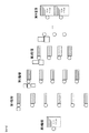
図23は、N個の階層からなるCNNに対し、中間バッファとしてバンドバッファを割り当てた場合の例を示す図である。図23において、各円は論理的な処理ノードを表し、各円の右に付属する四角がそれぞれの処理ノードに割り当てられたバッファを示している。ここでは入力画像である第0階層と出力層である第N階層の処理ノードには、1ページ分のフレームバッファ(ページバッファ)を割当て、他の中間層のノードにはバンドバッファを割り当てている。なお、本明細書では、中間層の出力結果保持バッファを特に中間バッファと呼んでいる。また、一部の円の左側に付属する四角は、その処理ノードのコンボリューションカーネルを例示するものであるが、図が複雑になるので一部のみしか記述していない。 FIG. 23 is a diagram illustrating an example in which a band buffer is assigned as an intermediate buffer to a CNN composed of N layers. In FIG. 23, each circle represents a logical processing node, and a square attached to the right of each circle indicates a buffer assigned to each processing node. Here, a frame buffer (page buffer) for one page is assigned to processing nodes in the 0th hierarchy that is an input image and an Nth hierarchy that is an output layer, and band buffers are assigned to nodes in other intermediate layers. . In this specification, the output result holding buffer of the intermediate layer is particularly called an intermediate buffer. The square attached to the left side of a part of the circle exemplifies the convolution kernel of the processing node, but only a part is described because the figure becomes complicated.
第0階層のノードは入力層であり、上述した通り便宜上処理ノードを割り当てているが、実際に演算処理を行うわけではなく、単に入力画像データが入力バッファメモリに格納されている状態を示す。 The node in the 0th hierarchy is an input layer, and processing nodes are assigned for convenience as described above. However, arithmetic processing is not actually performed, and the state where input image data is simply stored in the input buffer memory is shown.
また、最終層(第N階層)に割り当てられているバッファは出力バッファであって、この例では2つの処理ノードに対し入力画像サイズと同等のサイズのバッファがそれぞれ割り当てられている。もちろんこれら出力バッファの大きさは、このCNNによる演算結果を使用する、例えばCPU68による後処理部の都合によって定めればよいもので、コンボリューション演算の都合にはよらない。例えば、最終出力結果からある範囲の重心を取ってその座標に検出対象が存在するとする後処理を行うならば、出力バッファの大きさは重心を取る範囲の演算結果のみを保持できる大きさで十分である。
The buffer assigned to the last layer (Nth layer) is an output buffer. In this example, buffers having a size equivalent to the input image size are assigned to two processing nodes. Of course, the sizes of these output buffers may be determined by the convenience of the post-processing unit using the
図23のCNNでは、中間バッファ(第1階層〜第N−1階層の出力バッファ)を、図7で説明したのと同様のバンドバッファとして割り当てている。それぞれのバンドバッファの横幅は入力画像幅と同じであり、縦高さは先に説明した通り、接続される次階層の処理ノード(隣接上層処理ノード)のコンボリューションカーネルのサイズによって定まる最低限必要な高さとしている。尚、ここでは説明を簡単にするため、中間層の結果は後処理には用いないものとする。 In the CNN of FIG. 23, intermediate buffers (output buffers of the first layer to the (N-1) th layer) are allocated as band buffers similar to those described in FIG. The width of each band buffer is the same as the width of the input image, and the vertical height is the minimum required that is determined by the size of the convolution kernel of the next level processing node (adjacent upper layer processing node) as described above It is a height. Here, for the sake of simplicity of explanation, the result of the intermediate layer is not used for post-processing.
このように中間バッファを全てバンドバッファとして割り当てるとき、CNN全体の処理シーケンスは、ライン単位の演算処理を、処理ノードを切り替えて順に行っていくことになる。例えば第1階層の第1処理ノードのバンドバッファの高さが5だったとすると、5ライン分の演算処理が終わりその結果が格納されると、この処理ノードの演算結果を参照する第2階層の処理ノードが、1ライン分の単位演算処理を行うことができる。逆に第2階層の処理ノードの処理が終わらない限り、バンドバッファ内の5ラインの内の1ラインも破棄することはできない。そのため、新たな演算結果の格納場所がないため、第1階層の第1処理ノードは次の単位演算を行うことができない。こうして、第1階層の第1処理ノードは、その演算結果を必要とする全ての第2階層の処理ノードが1ライン分の単位演算処理を完了したら、第1階層の第1処理ノードは次の1ラインの単位演算処理を行うことができるということになる。 When all the intermediate buffers are assigned as band buffers in this way, the processing sequence of the entire CNN is performed in order by performing processing in units of lines by switching processing nodes. For example, if the height of the band buffer of the first processing node of the first hierarchy is 5, when the computation processing for 5 lines is finished and the result is stored, the second hierarchy referring to the computation result of this processing node is stored. A processing node can perform unit calculation processing for one line. On the contrary, as long as the processing of the processing node of the second hierarchy is not finished, one line out of the five lines in the band buffer cannot be discarded. For this reason, since there is no storage location for a new calculation result, the first processing node in the first hierarchy cannot perform the next unit calculation. Thus, the first processing node of the first hierarchy, when all the processing nodes of the second hierarchy that require the calculation result have completed the unit calculation processing for one line, the first processing node of the first hierarchy This means that one line unit calculation processing can be performed.
従って、CNN全体で処理が1ライン単位ずつ進んでいくことになるので、全ての中間バッファは、基本的に同時に存在している必要がある。ここで、
全階層数(入力層除く): N
階層番号変数(中間層): l=1,2,…,N−1
各階層特徴数: Fl
特徴番号(注目階層の注目特徴): f=fl=1,…,Fl
前階層の特徴番号: f’=fl-1
入力画像サイズ(水平方向,垂直方向):IX,IY
カーネルサイズ(水平方向,垂直方向):WX(l,f,f’)、WY(l,f,f’)
バンドバッファ高さ:BY(l,f)
バンド中間バッファ必要容量:SB
とすると、全ての中間バッファを最低限必要なサイズのバンドバッファとして割り当てるときに必要となるトータルのサイズSBは、

として求めることができる。
Accordingly, since the processing proceeds in units of one line at a time in the entire CNN, all intermediate buffers must basically exist at the same time. here,
Total number of layers (excluding input layer): N
Layer number variable (middle layer): l = 1, 2,..., N−1
Number of features in each layer: Fl
Feature number (attention feature of attention hierarchy): f = f l = 1,..., F l
Feature number of previous layer: f ′ = f l−1
Input image size (horizontal and vertical): I X , I Y
Kernel size (horizontal, vertical): W X (l, f, f '), W Y (l, f, f')
Band buffer height: B Y (l, f)
Band intermediate buffer required capacity: S B
When the size S B of the total needed to assign all the intermediate buffer as a band buffer minimum required size,
Can be obtained as
上記計算では、
・ネットワーク演算を構成する全ての処理ノードの各々に必要な中間バッファのサイズを当該処理ノードの後段に接続される処理ノードが必要とするデータ量に設定し、
・それら中間バッファのサイズを合計することにより、ネットワーク演算に必要なメモリ量を算出している。
In the above calculation,
Set the size of the intermediate buffer required for each of all processing nodes constituting the network operation to the amount of data required by the processing node connected to the subsequent stage of the processing node,
-The amount of memory required for network operation is calculated by summing up the sizes of these intermediate buffers.
一方、図24は、図23で示したCNNと同じネットワーク構成のCNNに対し、中間バッファとしてページバッファを用いた場合の例を示している。入力層および出力層のバッファは図23と同様、ネットワーク構成や演算シーケンスによらず定まるもので、ここではやはりページバッファとしてある。 On the other hand, FIG. 24 shows an example in which a page buffer is used as an intermediate buffer for a CNN having the same network configuration as the CNN shown in FIG. As in FIG. 23, the input layer and output layer buffers are determined regardless of the network configuration and the operation sequence, and are also used here as page buffers.
図24では、第1階層から第N−1階層までの夫々の処理ノードに入力画像サイズと同等のサイズのページバッファが割り当てられている。しかしながら、これらのページバッファは、全て同時に存在している必要は無い。 In FIG. 24, a page buffer having a size equivalent to the input image size is allocated to each processing node from the first layer to the (N-1) th layer. However, these page buffers need not all exist at the same time.
まず第1階層の各ノードに注目すると、それぞれのノードにおける演算処理は、第0階層すなわち入力画像のみを参照して行われる。本実施形態において入力画像データは全てメモリ上に格納されているので、各ノードは必要なときに必要な範囲のデータを参照可能である。また、各ノードの出力格納バッファとして、1ページ分のバッファが用意されているので、バンドバッファの場合と異なりラインの上書きを気にすることなくいつでも演算結果を格納可能である。 First, paying attention to each node in the first hierarchy, the arithmetic processing in each node is performed with reference to the 0th hierarchy, that is, only the input image. In the present embodiment, since all input image data is stored in the memory, each node can refer to data in a necessary range when necessary. In addition, since a buffer for one page is prepared as an output storage buffer for each node, the calculation result can be stored at any time without worrying about overwriting of the line unlike the case of the band buffer.
次に第2階層の各処理ノードに注目すると、これらのノードは第1階層の処理結果を参照する。従って、第1階層の各処理ノードが、1ページ分の処理を終えた後であれば、必要な参照データは入力画像と同様ページで保持された状態となるので、所望のときに所望の範囲を参照することができる。以下の層も同様で、基本的に前段の階層の処理が完了しており参照データがページ分揃っていれば処理可能である。 Next, when attention is paid to each processing node in the second hierarchy, these nodes refer to the processing results in the first hierarchy. Therefore, if each processing node in the first hierarchy has finished processing for one page, the necessary reference data is held in the same page as the input image. Can be referred to. The same applies to the following layers. Basically, the processing of the previous layer is completed, and the processing can be performed if the reference data is prepared for the pages.
逆に、各階層の処理ノードは演算処理を行うに当たって、前々階層の処理結果は必要としない。つまり、ある処理ノードの演算処理を開始するに当たって、前階層の全処理ノードの演算が1ページ分完了しているならば、更にその前の階層の処理ノードの中間バッファは開放してしまって構わないことになる。 Conversely, the processing nodes of each hierarchy do not need the processing results of the previous hierarchy when performing the arithmetic processing. In other words, when the calculation process of a certain processing node is started, if the calculation of all the processing nodes in the previous hierarchy is completed for one page, the intermediate buffer of the processing node in the previous hierarchy may be released. There will be no.
従って、各処理ノードでライン単位の演算処理を順次行うに当たって、まずは第1階層に属する処理ノードでのみ順次単位演算を行う。そして、第1階層の全ての処理ノードで1ページ分の演算処理が完了した後に、第2階層の処理ノードでの単位演算処理を開始する。これを順に次の階層にたいしても繰り返してゆく、というように、単位演算処理シーケンスを組むと、中間バッファは1時期に連続する2階層のみで存在していれば、最終層までの演算が可能となる。より一般化して言うと、
・1つの階層に属する全ての処理ノードの出力が生成された後に次階層に属する処理ノードの演算処理を開始するように制御し、
・N番目の階層に属する全ての処理ノードの出力が生成された後、N−1番目の階層に属する全ての処理ノードが使用していた中間バッファ領域を開放してN+1番目以降の階層に属する処理ノードの中間バッファ領域に割り当て可能にする。
こうして、1階層の演算処理が完了する毎に、その前の階層のページバッファを、次階層の中間バッファとして再利用するようにすることにより、トータルの中間バッファ必要サイズを減らすことが可能となる。以下、この方式をページバッファ方式という。
Therefore, in order to sequentially perform the arithmetic processing in units of lines in each processing node, first, the unit arithmetic is sequentially performed only in the processing nodes belonging to the first hierarchy. Then, after the calculation processing for one page is completed in all the processing nodes in the first hierarchy, the unit calculation processing in the processing nodes in the second hierarchy is started. If a unit calculation processing sequence is set up such that this is repeated in sequence for the next layer, the intermediate buffer can be calculated up to the last layer if it exists in only two layers that are continuous at one time. Become. In more general terms,
-Controls to start arithmetic processing of processing nodes belonging to the next hierarchy after the output of all processing nodes belonging to one hierarchy is generated,
After the outputs of all processing nodes belonging to the Nth hierarchy are generated, the intermediate buffer area used by all the processing nodes belonging to the (N−1) th hierarchy is released and belong to the (N + 1) th and subsequent hierarchies Allows allocation to the intermediate buffer area of the processing node.
In this way, each time the calculation processing of one layer is completed, the page buffer of the previous layer is reused as the intermediate buffer of the next layer, thereby reducing the total required intermediate buffer size. . Hereinafter, this method is referred to as a page buffer method.
ここで、ページ中間バッファ必要容量:SP
とすると、
![]()
として、ページで中間バッファを構成した際(ページバッファ方式を採用した際)のトータルの必要サイズを求めることができる。この計算は、ネットワーク構成において連続する2つの階層の組に属する全ての処理ノードが生成する演算結果データのサイズの合計を全ての組について計算し、その内の最大となるサイズを必要なメモリ量とするものである。
Here, page intermediate buffer required capacity: S P
Then,
![]()
As a result, the total required size when the intermediate buffer is configured with pages (when the page buffer method is adopted) can be obtained. In this calculation, the total size of the operation result data generated by all the processing nodes belonging to a set of two consecutive hierarchies in the network configuration is calculated for all the sets, and the maximum size among them is calculated as the required amount of memory. It is what.
(2)、(3)式から分かる通り、バンド中間バッファ必要容量SBとページ中間バッファ必要容量SPのどちらが小さくなるかは、CNNネットワークの各論理的処理ノードの接続構造と、各ノードのコンボリューションカーネルサイズに依存する。一般的に、ネットワークの階層数が少なくカーネルサイズが小さければ、バンドバッファ方式の割当てが有利となるが、階層数が多くかつ各階層に属する処理ノード数が比較的少なければページバッファ方式の割当てが有利となる。 As can be seen from the equations (2) and (3), which of the band intermediate buffer required capacity S B and the page intermediate buffer required capacity S P becomes smaller depends on the connection structure of each logical processing node of the CNN network and each node. Depends on the convolution kernel size. In general, if the number of network hierarchies is small and the kernel size is small, band buffer allocation is advantageous. However, if the number of hierarchies and the number of processing nodes belonging to each hierarchy is relatively small, page buffer allocation is possible. It will be advantageous.
通常、システムとして、中間バッファに用いることのできるメモリの上限サイズは一定である。この条件サイズをMとする。特に本実施形態のような専用のパターン検出装置においては、中間バッファに割り当てるメモリサイズは、小さければ小さいほど良いという訳ではなく、割り当て可能なサイズM以下であれば全く問題ない。 Usually, as a system, the upper limit size of the memory that can be used for the intermediate buffer is constant. Let this conditional size be M. In particular, in the dedicated pattern detection apparatus as in the present embodiment, the smaller the memory size allocated to the intermediate buffer is, the better.
また、上述のようにバンドバッファ方式の場合と、ページバッファ方式の場合では、単位演算の処理シーケンスが異なる。特にページバッファ方式では、一つの処理ノードでの単位演算を1ページ分連続して行うことも可能である。このようなシーケンスにすると、実装によっては、処理ノード切り替えのオーバーヘッドを省略でき、バンドバッファ割当て方式よりトータル演算時間を若干短くできる可能性がある。従って、SBとSPのどちらもM以下になる場合は、より小さい方を選ぶのではなく、ページバッファ方式を優先する方がよい。 Further, as described above, the unit operation processing sequence differs between the band buffer method and the page buffer method. In particular, in the page buffer method, it is also possible to perform unit operations for one page continuously in one processing node. With such a sequence, depending on the implementation, the processing node switching overhead can be omitted, and the total calculation time may be slightly shorter than the band buffer allocation method. Therefore, when both S B and S P are equal to or less than M, it is better not to select the smaller one but to give priority to the page buffer method.
ところで、図11で示すように、ページバッファ割当て方式の場合、最終出力層の出力バッファも他の中間バッファと領域を兼用することが可能である。そこで、(3)式の変わりに、以下の(4)式を用いる。 By the way, as shown in FIG. 11, in the case of the page buffer allocation method, the output buffer of the final output layer can also be used as an area with another intermediate buffer. Therefore, the following equation (4) is used instead of equation (3).
![]()
![]()
また、中間バッファだけでなく最終出力層も含めて割当て可能なサイズをM’とすると、以下の(5)式のように表される。 Further, when the size that can be allocated including not only the intermediate buffer but also the final output layer is M ′, the following expression (5) is expressed.
![]()
![]()
すなわち、ページバッファ方式での割当てが可能かどうかを判断するのに、(3)式の代わりに(4)式を用いて、M’と比較するようにしてもよい。つまりページバッファ方式の場合は、実質割当て可能なサイズを増やすことができる。このようにすると、さらにメモリ使用効率を上げられる。 In other words, in order to determine whether or not the assignment by the page buffer method is possible, the expression (4) may be used instead of the expression (3) and compared with M ′. That is, in the case of the page buffer method, the size that can be substantially allocated can be increased. In this way, the memory usage efficiency can be further increased.
以下、図8および図26、27に示すフローチャートを用いて、本実施形態の階層型ネットワークによる演算処理動作を詳細に説明する。図8はCPU68での一連の検出処理動作を示すフローチャートである。CPU68におけるソフトウェアによる処理は、所定の設定処理等を行った後、画像入力部61やCNN処理部63等のハードウェア処理回路部をドライブする。
Hereinafter, the arithmetic processing operation by the hierarchical network according to the present embodiment will be described in detail with reference to the flowcharts shown in FIGS. FIG. 8 is a flowchart showing a series of detection processing operations in the
まず、ステップS801において、CPU68は、検出処理の開始に先立ち、変数やレジスタ等の各種初期化処理を実行する。各処理部はCPU68の初期化指示に従って内部のレジスタ、メモリ等を初期化する。またここでは、入力画像サイズ全域を処理領域とする初期設定も行う。本処理を含め、以降CPU68は、ブリッジ65及び画像バス64を介してCNN処理部63や他のハードウェア回路部にアクセスし、CPUバスアクセス制御部113を介して所定のレジスタやメモリにデータを設定することが可能となる。また、本初期化処理においては、演算部101内の重み係数記憶部1205(図12)へ、本パターン検出装置で対応する全ての検出対象に対する全ての処理ノードのコンボリューションカーネルの係数データをロードする。本パターン検出装置は、コンボリューションカーネルの重み係数、シーケンス情報、ネットワーク構成情報等を入れ替える事で、同一のハードウェアで様々な検出対象に対応することができるが、そのためのカーネルをここで一通りロードしておく。
First, in step S801, the
次に、ステップS802において、CPU68は、ユーザからの検出対象の選択を受け付ける。ここでは、本パターン検出装置が対応する全ての検出対象の中から、画像中より検出したい所望の検出対象がユーザにより選択される。
Next, in step S802, the
検出対象が決定したら、ステップS803でネットワーク構成管理部108のネットワーク構成情報設定部110にネットワーク構成情報を設定する。ネットワーク構成情報はネットワークの結合関係を指定するテーブルであり、レジスタファイル或いはRAM等により構成される。ネットワーク構成情報も重み係数と共に検出対象に応じて異なる値となる。
When the detection target is determined, network configuration information is set in the network configuration
図9はネットワーク構成情報の一例を示す図であり、図14に示したCNNの構成情報を表現している。図9において、「対象処理ノード」は図14に示すネットワークの論理的な第0から第8処理ノードに対応する。なお、論理的な処理ノードとは、演算部101を時分割利用する事により実現する論理的な演算処理の単位である。ここで第0処理ノードは入力画像データ面に対応する処理ノードであって便宜上第0処理ノードとしているが、実際には演算は実行しない。
FIG. 9 is a diagram showing an example of the network configuration information, and expresses the configuration information of the CNN shown in FIG. 9, “target processing nodes” correspond to logical 0th to 8th processing nodes of the network shown in FIG. The logical processing node is a unit of logical arithmetic processing realized by using the
「隣接下層処理ノード数」とは、処理ノードが演算実行時に必要とする下位層の接続数を示す。例えば第4処理ノードの場合、3つの下位層に接続される。ネットワーク構成管理部108では、当該隣接下層処理ノード数に応じてメモリアクセスと演算を制御する。
The “number of adjacent lower-layer processing nodes” indicates the number of lower-layer connections that a processing node requires when executing an operation. For example, in the case of the fourth processing node, it is connected to three lower layers. The network
「隣接下層処理ノード」は処理ノードの演算時に必要とする下位層の処理ノードを指定する情報である。例えば第4処理ノードは、第1処理ノード、第2処理ノード、第3処理ノードに接続される。つまり、第4処理ノードの演算時は、第1〜3処理ノードの演算結果が参照データとして使用される。 The “adjacent lower layer processing node” is information for designating a lower layer processing node that is necessary for processing of the processing node. For example, the fourth processing node is connected to the first processing node, the second processing node, and the third processing node. That is, at the time of calculation of the fourth processing node, the calculation result of the first to third processing nodes is used as reference data.
「演算種別」は実行する演算の種別を示す情報であり、CNN演算の場合、演算種別に応じて重み係数を選択することになる。すなわち、演算部101が図12に示す構成の場合、ここでの演算種別番号が係数を選択するための「カーネル選択信号」に相当する。CNN処理の場合、各処理ノードは、「カーネル選択信号」に応じて選択した、それぞれ異なる重み係数を用いて、コンボリューション演算を実行する。
“Calculation type” is information indicating the type of calculation to be executed. In the case of CNN calculation, a weighting factor is selected according to the calculation type. That is, when the
「参照データ幅」は「演算種別」に対応するコンボリューションカーネルの幅に相当し、「参照データ高さ」はコンボリューションカーネルの高さに相当する。 “Reference data width” corresponds to the width of the convolution kernel corresponding to “calculation type”, and “reference data height” corresponds to the height of the convolution kernel.
また、「処理開始ライン」は、該処理ノードにおいて有効な演算出力が可能な画像位置を表す。先に説明したように、コンボリューション演算はカーネルサイズの範囲の周辺画素を掃き寄せる演算であるので、カーネル参照範囲が参照画像データの有効範囲外にはみ出す場合には、有効な演算結果を得ることができない領域となる。横方向には図22の領域2206が有効範囲外の領域(無効領域)に相当するが、同様に縦方向にも無効領域が存在する。これは処理ノードのカーネルサイズに依存し、階層を経ることによって蓄積される。本実施形態のパターン検出装置のCNNでは、ライン単位に処理を行うので、無効領域のラインは計算をスキップした方が全体の処理を高速化できる。つまり、「処理開始ライン」までは、その処理ノードにおける演算の無効領域となるので、処理をスキップすることができる。ちなみに、本実施形態では入力画像の最初のラインの番号を0として開始している。また、同様に開始ラインのみならず終了ラインも存在するが、これは入力画像のライン数IYから「処理開始ライン」を引いてさらに1を減じたライン番号となる。
The “processing start line” represents an image position where an effective calculation output can be performed at the processing node. As explained earlier, the convolution operation is an operation that sweeps the surrounding pixels of the kernel size range, so if the kernel reference range is outside the effective range of the reference image data, an effective operation result is obtained. It is an area that can not be. In the horizontal direction, an
尚、本実施形態では、入力画像に対して各処理ノードは演算可能な最大範囲を演算するように設定しているが、最終的に演算結果を利用する処理ノードの利用したい演算範囲から、前階層に向かって順に演算範囲を逆算してももちろんかまわない。この場合は終了ラインも合わせて情報として持つようにすると、より演算を無駄無く行える。 In this embodiment, each processing node is set to calculate the maximum range that can be calculated with respect to the input image. However, from the calculation range to be used by the processing node that finally uses the calculation result, Of course, the calculation range may be calculated backward in order toward the hierarchy. In this case, if the end line is also included as information, the calculation can be performed more efficiently.
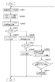
次にステップS804において、CPU68は、中間バッファ割当て方式を選択する。この処理の詳細を示すのが、図26のフローチャートである。中間バッファ割当て方式の選択処理では、まずステップS2601において、CPU68は、設定されている入力処理画像サイズIX,IYを取得する。そしてステップS2602において、CPU68は、中間バッファとして利用可能なサイズMを計算する。このサイズMは、ワークメモリ102で利用可能な容量から、入力画像バッファサイズや出力バッファサイズその他の処理に必要なサイズを差し引いた値となる。
In step S804, the
そして、ステップS2603において、CPU68は、まずページバッファ方式で中間バッファを割り当てた場合に必要な容量SPを計算する。この容量SPは、上述した式(3)で求めることができる。ステップS2604において、このSPがM以下であるかどうかを確認する。M以下であれば、ステップS2605において、CPU68は、ページバッファ方式を今回の中間バッファ割当て方式として選択し、本処理終了する。尚、ここで使用する値として、上述したように、SPとMの代わりにSP'とM'を用いてももちろん良く、このようにするとよりページバッファ方式の選択される率が高まる。
Then, in step S2603,
一方、MよりSPが大きい場合には、処理はステップS2604からステップS2606へ進む。ステップS2606において、CPU68は、バンドバッファ方式で割り当てた場合の中間バッファ容量SBを計算する。これは上述の式(2)により求めることができる。次に、ステップS2607において、SBがM以下であるかどうかを確認する。M以下であれば、ステップS2608において、CPU68は、バンドバッファ方式を今回の中間バッファ割当て方式として選択し、本処理を終了する。このように、本実施形態では、複数種類のバッファ割り当て方法のうち、必要となるバッファの合計サイズが中間バッファとして利用可能なメモリ量以下(M以下)になるバッファ割り当て方法が選択される。
On the other hand, if S P is greater than M, the process proceeds from step S2604 to step S2606. In step S2606,
SP、SBが共にMより大きい場合には、複数種類のバッファ割り当て方法のうち、必要となるバッファの合計サイズが中間バッファとして利用可能なメモリ量以下(M以下)になるバッファ割り当て方法がない。従って、そのままでは本パターン検出装置で演算処理を行うことができない。この場合、ステップS2609において、CPU68は、元の入力画像サイズを2分割したサイズを新たな処理画像サイズとして再設定する。この分割処理は、図25に示すように、カーネルのオーバーヘッドを考慮して行われる。図25において(a)は元の入力画像を示し、太線枠は最終層における累積カーネル領域2501を示す。なお、ここで累積カーネル領域とは、最終層処理ノードの参照範囲が有効になるように、順に隣接下層処理ノードを遡って入力画像まで行き着いたときの参照範囲のことである。
When S P and S B are both larger than M, there is a buffer allocation method in which the total size of necessary buffers is less than or equal to the amount of memory available as an intermediate buffer (M or less) among a plurality of types of buffer allocation methods. Absent. Therefore, it is impossible to perform arithmetic processing with this pattern detection apparatus as it is. In this case, in step S2609, the
これを図25の(b)の点線領域に示すように、左右に2分割することを考える。左右それぞれの点線領域を有効とするには、累積カーネル領域2501を考慮すると、網掛けで示した領域まで入力する必要があることが分かる。
Consider that this is divided into left and right as shown by the dotted line area in FIG. In order to validate the left and right dotted areas, it is understood that it is necessary to input up to the shaded area considering the accumulated
従って、オーバーヘッドを考慮した2分割とは、図25の(c)に示すものとなる。すなわち、入力画像サイズ(a)の単純な2分割の領域に、累積カーネル領域2501の1/2(奇数時切捨て)の幅を加えたものとなる。このように分割して演算した結果の両点線枠内の領域を合成すれば、図25の(d)に示すように、元の入力画像にCNNによる演算を行ったのと同等の演算結果を得ることができる。なお、このように入力データを分割して処理する方式をタイル処理と呼ぶこともある。 Therefore, the division into two considering the overhead is as shown in (c) of FIG. That is, it is obtained by adding a half of the cumulative kernel area 2501 (truncated when odd) to a simple two-divided area of the input image size (a). If the regions within the two dotted line frames resulting from the division and calculation are combined in this way, as shown in (d) of FIG. 25, the calculation result equivalent to the calculation by the CNN is performed on the original input image. Can be obtained. Note that the method of dividing and processing input data in this way is sometimes called tile processing.
本実施形態においては、図25に示したような横方向の分割処理を優先的に行う。なぜならば、縦方向の分割処理では、ページ方式の中間バッファ使用容量は減るが、バンド方式の中間バッファ方式は変わらないからである。横方向の分割では、どちらの方式であっても一時的なトータル使用容量も削減される。分割可能なサイズは、累積カーネル領域の大きさによって決まる(領域以上のサイズが必要)ので、横方向がこれ以上分割できなくなったら、縦方向の分割を行う。尚、本処理では、分割をするたびに初期値1の分割カウンタをインクリメントするとともに、分割方向も合わせて記憶している。
In the present embodiment, the horizontal division process as shown in FIG. 25 is preferentially performed. This is because, in the vertical division processing, the page-type intermediate buffer use capacity is reduced, but the band-type intermediate buffer method does not change. In the division in the horizontal direction, the temporary total used capacity is reduced with either method. Since the size that can be divided is determined by the size of the accumulated kernel area (a size larger than the area is necessary), if the horizontal direction cannot be further divided, the vertical division is performed. In this process, the division counter of
ステップS2610において、分割後のサイズが累積カーネルサイズより大きいことを確認し、再度ステップS2601からの処理を繰り返す。もし、上述のように縦方向分割を駆使しても、分割後サイズが累積カーネルサイズよりも小さくなってしまった場合、その検出処理は本CNN演算装置で実行することができない。よって、処理はステップS2611に進み、CPU68は、処理不可能の判断を行う。これは全処理ノードのカーネルサイズと割当て可能な中間バッファ容量最大値によって決まるので、通常はこのようなことにならない構成を取る。
In step S2610, it is confirmed that the size after division is larger than the accumulated kernel size, and the processing from step S2601 is repeated again. If the post-division size becomes smaller than the cumulative kernel size even if the vertical division is used as described above, the detection process cannot be executed by this CNN arithmetic unit. Therefore, the process proceeds to step S2611, and the
図8に戻り、ステップS805において、CPU68は、ステップS804の選択処理において処理不可能と判別されていないことを確認する。処理不可能と判別されていた場合、処理はステップS805からステップS819へ進み、終了判定処理(後述)が実行される。但し、通常はそのようなことのない構成をとる。
Returning to FIG. 8, in step S <b> 805, the
ステップS806において、CPU68は、ステップS804の選択処理で選択された方式がページバッファ方式であったかどうかを判定する。ページバッファ方式の場合、処理はステップS807のページバッファ方式シーケンス設定およびステップS808のページバッファ方式中間バッファ設定へ進む。一方、バンドバッファ方式が選択されていた場合、処理はステップS809のバンドバッファ方式シーケンス設定およびステップS810のバンドバッファ方式中間バッファ設定へと進む。
In step S806, the
ステップS807のページバッファ方式シーケンス設定処理と、ステップS809のバンドバッファ方式シーケンス設定処理において、CPU68は、シーケンス制御部109のシーケンス情報設定部111にシーケンス情報を設定する。シーケンス情報とは、時分割処理する演算処理単位(本実施形態ではライン単位)のシーケンス動作を規定するテーブル情報であり、RAM等に保持される。なお、上述したように、シーケンス情報はRAM69に格納され、CPU68からCNN処理部63ないに書き込まれる。
In the page buffer method sequence setting process in step S807 and the band buffer method sequence setting process in step S809, the
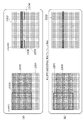
図10はシーケンス情報テーブルの例であって、図14に示したCNNネットワークで処理を行う場合の、(a)がバンドバッファ方式、(b)がページバッファ方式の場合のシーケンスを示している。ここで、「シーケンス番号」はライン単位での処理の順序を示す番号で、テーブルの配列Indexに相当するので実際に数字を保持する必要はない。「処理ノード番号」は図14の処理ノード番号であって、シーケンス番号に対応する論理的な実行処理ノードを示す。即ち、シーケンス番号1のとき、第1処理ノードに対して演算処理を実行し、シーケンス番号2においては第2処理ノードのライン単位演算処理を実行する。処理ラインは、該シーケンス番号の処理のとき該処理ノードが出力するラインの位置を示している。各処理ノードの処理ラインは、図9で説明した「処理開始ライン」より順にスタートし、1ライン処理が完了する毎にインクリメントするものである。従って、本実施形態のように、テーブル上にシーケンス番号に対応する番号として明記しなくとも、各処理ノード毎に現在の処理ラインをレジスタ等で記憶しておくようにしてもよい。
FIG. 10 is an example of a sequence information table, and shows a sequence when (a) is a band buffer method and (b) is a page buffer method when processing is performed in the CNN network shown in FIG. Here, the “sequence number” is a number indicating the order of processing in line units, and corresponds to the array index of the table, so it is not necessary to actually hold a number. “Processing node number” is the processing node number in FIG. 14 and indicates a logical execution processing node corresponding to the sequence number. That is, when the sequence number is 1, the arithmetic processing is executed on the first processing node, and at the
図10の(a)は、バンドバッファ方式の場合のシーケンス情報テーブルの例であり、1ライン単位処理するごとに、処理ノードを切り替えている。例えば、シーケンス番号“21”までは、処理ノード番号“1”〜“3”までの演算を行っており、シーケンス番号“22”において処理ノード番号4の処理を開始している。これは、シーケンス番号“21”までで、処理ノード番号4の1ライン分の演算処理に必要な参照画像が演算されたためである。このようにバンドバッファ方式では、演算可能になった処理ノードから速やかにライン単位演算を行っていくことにより、参照される側のバッファをライン単位で順次開放可能にしている。これにより、中間バッファを必要最小限の循環数のリングバッファとして構成することが可能となる。
FIG. 10A is an example of a sequence information table in the case of the band buffer method, and the processing node is switched every time one line unit is processed. For example, up to the sequence number “21”, the computations of the processing node numbers “1” to “3” are performed, and the processing of the
図10の(b)は、ページバッファ方式の場合のシーケンス情報テーブルの例であり、特定処理ノードの単位演算を連続して行い、該特定処理ノードの演算が有効領域全域について完了した後に、次の処理ノードの演算を開始している。このようにすると、図9および図14のCNNネットワークにおいて、例えば処理ノード番号“4”と“5”の全有効領域演算が完了すると、処理ノード番号“1”〜“3”の出力に割り当てられていた中間バッファ領域は不用となる。従って、最終階層まで演算の完了していないこの時点で、このバッファ領域を開放して同領域を処理ノード番号7、8、9の出力用として割り当てることができるようになる。
FIG. 10B is an example of a sequence information table in the case of the page buffer method. After the unit calculation of the specific processing node is continuously performed and the calculation of the specific processing node is completed for the entire effective area, The operation of the processing node has started. In this way, in the CNN network of FIG. 9 and FIG. 14, for example, when all the valid area computations for the processing node numbers “4” and “5” are completed, the processing node numbers “1” to “3” are assigned. The intermediate buffer area that has been used becomes unnecessary. Accordingly, at this point in time when the calculation is not completed up to the final hierarchy, the buffer area can be released and the same area can be allocated for output of the
ステップS808のページバッファ方式による中間バッファ設定およびステップS810のバンドバッファ方式による中間バッファの設定では、各処理ノードに必要な中間バッファ領域が割り当てられる。当該処理は、論理的な処理ノードの数に対応する数のレジスタセット(リングバッファ設定部104-1〜104-n)に値を設定することにより行われる。図14および図9に示したネットワーク構造の場合、8個のリングバッファ設定部(104-1〜104-8)に所定の値を設定する必要がある。 In the intermediate buffer setting by the page buffer method in step S808 and the intermediate buffer setting by the band buffer method in step S810, a necessary intermediate buffer area is allocated to each processing node. This processing is performed by setting values in the number of register sets (ring buffer setting units 104-1 to 104-n) corresponding to the number of logical processing nodes. In the case of the network structure shown in FIGS. 14 and 9, it is necessary to set predetermined values in the eight ring buffer setting units (104-1 to 104-8).
リングサイズ設定部106には対応する論理的な処理ノードのリングバッファの高さ(リングカウンタの循環数)が設定される。バンドバッファ方式の場合、この循環数は当該処理ノードの出力を参照する次階層の処理ノード(隣接上層処理ノード)のコンボリューションカーネルのうちの最大の高さに相当する。一方、ページバッファ方式の場合は、リングサイズ設定部106に設定されるリングバッファの高さは、入力画像のライン数(もしくは各処理ノードの有効領域ライン数)と同じになり、当該リングバッファは実質循環させずに使用されることになる。オフセットアドレス設定部107には、対応する処理ノードのリングバッファ先頭アドレスが設定される。
In the ring
図11は図14に示すネットワークを実現する場合の処理ノードとオフセットアドレス及びリングバッファの高さの関係の一例を示すメモリマップである。図11において、(a)がバンドバッファ方式の場合のメモリマップを、(b)がページバッファ方式の場合のメモリマップを示す。ADRx(x:0〜8)はオフセットアドレス、BHx(x:0〜3)がリングバッファの高さ(循環数)に相当する。Ixは入力画像データの幅を示す。図中、第0処理ノードのための領域とは、入力画像データを保持するページバッファ領域である。つまりBH0は入力画像データの高さIYに等しい。また本実施形態においてBH1は、次階層(第2階層)の第4処理ノード及び第5処理ノードのカーネルサイズのうちの大きい方、すなわち図9の構成情報テーブルから9ライン分のサイズが設定される。同様にBH2には13、BH3には17ライン分のサイズが設定される。一方、ページバッファ方式の場合は、全ての領域の高さはBH0となり、またいくつかの領域は複数の処理ノードによって利用される。本実施形態ではこのように、メモリ102を所定の領域に分割して各領域をサイズの異なるリングバッファ或いはフレームバッファとして利用する。
FIG. 11 is a memory map showing an example of the relationship between processing nodes, offset addresses, and ring buffer heights when realizing the network shown in FIG. 11A shows a memory map in the case of the band buffer method, and FIG. 11B shows a memory map in the case of the page buffer method. ADRx (x: 0 to 8) corresponds to the offset address, and BHx (x: 0 to 3) corresponds to the height (circulation number) of the ring buffer. I x indicates the width of the input image data. In the figure, the area for the 0th processing node is a page buffer area for holding input image data. That is, BH0 is equal to the height I Y of the input image data. In this embodiment, BH1 is set to the larger of the kernel sizes of the fourth processing node and the fifth processing node of the next layer (second layer), that is, the size corresponding to 9 lines from the configuration information table of FIG. The Similarly, BH2 is set to 13 and BH3 is set to 17 lines. On the other hand, in the case of the page buffer method, the height of all areas is BH0, and some areas are used by a plurality of processing nodes. In this embodiment, as described above, the
以上の各種設定処理により、後述のステップS814で実行されるCNN演算処理におけるネットワーク演算処理の実行手順が決定されることになる。すなわち、選択された中間バッファ割り当て方式(上記例ではバンドバッファ方式かページバッファ方式のいずれか)に応じてネットワーク演算処理における処理ノードの実行順が決定される。以上の各種設定を終了すると、ステップS811から、画像入力部61、前処理部62、CNN処理部63に対して各処理の開始を指示する。
Through the various setting processes described above, the execution procedure of the network calculation process in the CNN calculation process executed in step S814 described later is determined. That is, the execution order of the processing nodes in the network operation processing is determined according to the selected intermediate buffer allocation method (in the above example, either the band buffer method or the page buffer method). When the above various settings are completed, from step S811, the
まずステップS811において、CPU68より処理開始の指示を受けた画像入力部61は、1フレーム分の画像データを取得し、図示しない内部バッファに格納する。画像入力部61は、画像データの格納が終了するとCPU68に対して画像取得終了割り込みを発生する。CPU68はこの割り込みを検知すると、DMAC66を起動して取得した画像データを前処理部62の内部メモリ(図示しない)に転送する。前処理部62は画像データの転送が終了すると、前処理を開始する。前処理部62は、例えば、予め指定するコントラスト補正情報に従って画像データのコントラストを補正する。前処理部62は補正処理を終了するとCPU68に対して割り込みを発生する。CPU68はこの割り込みを検知すると、再びDMAC66を起動し、前処理部62によって補正された画像データをCNN処理部63内のメモリ102の入力画像バッファ(図11の第0処理ノード領域に相当)に転送する。
First, in step S811, the
次に、ステップS812において、CPU68は、分割処理カウンタを設定する。これは上述のステップS804において、中間バッファ割当て方式の選択処理を行った際に、入力画像(処理画像)が分割指定された場合に1よりも大きい値となる。分割無しの場合は1が設定される。そしてステップS813において、CPU68は、分割無しの場合は画像全域を、分割有りの場合は初回の処理領域(例えば図25の左右どちらか)を、処理領域として設定する。
Next, in step S812, the
次に、ステップS814において、CPU68がCNN処理部63に対し演算開始トリガを送ることにより、検出処理が開始される。CNN処理部63におけるハードウェア処理について、図27のフローチャートを参照して、以下に説明する。
Next, in step S814, the
先ず、ステップS2701において、シーケンス制御部109は、処理ノードを決定する。シーケンス制御部109は、上述したシーケンス情報設定部111に記載されたシーケンス情報テーブルを、ライン単位演算毎に上から辿り、毎回の処理ノードを決定する。図10の(a)に示す例の場合、初回のシーケンスでは処理ノード番号1を選択する。シーケンス制御部109はシーケンス回数をカウントするシーケンスカウンタを有し、シーケンス単位(この場合ライン単位の処理毎)でカウントアップする。このカウンタは初期値1であって、図10のシーケンス情報テーブルのIndexとして使用できる。つまり、シーケンス制御部109は、シーケンスカウンタをアドレスとしてシーケンス情報テーブル(図10)を参照する事により処理対象処理ノードを決定する。
First, in step S2701, the
ステップS2702において、処理ノードの演算に必要な参照データをメモリ102から読み出す。より具体的には、先ず、ネットワーク構成管理部108がシーケンス制御部109の出力するシーケンス指示情報に従って参照データに対応するリングバッファ設定部104を選択する。すなわち、リングバッファ設定部104-1〜104-nの何れかを選択する。例えば、ステップS2701で第1処理ノードが選択された場合、図9に示すネットワーク構成情報テーブルの内容に従って、「接続ノード数が1」「接続先ノードが第0処理ノード」「演算種別1」が決定される。ネットワーク構成管理部108はこのネットワーク構成情報テーブルの内容に従ってノード選択信号をセレクタ1121,1122に出力し、参照すべきリングバッファに対応したリングバッファ設定部の出力を選択する。例えば初回のシーケンスでは対象処理ノードが第1処理ノードであるので、その隣接下層ノードである第0処理ノードに対応する選択信号を出力する。選択されたリングバッファ設定部の情報(この場合、第0処理ノードに対応したリングカウンタ値、オフセットアドレス値)に従ってメモリアクセス制御部103は読み出すメモリの先頭アドレスを生成する。
In step S2702, reference data required for processing node processing is read from the
図16はメモリアクセス制御部103の内部を説明する図である。また、図15はメモリアクセス制御部103の参照データの読み出し動作を説明する図である。
FIG. 16 is a diagram for explaining the inside of the memory
図15において、1501はバンドバッファ方式におけるリングバッファ、1502は演算するコンボリューションカーネルの参照ウインドウに相当する大きさ、1503はコンボリューションカーネルの重み係数列の様子を説明する図である。ここではコンボリューションカーネルサイズが6×6の場合について例示している。重み系数列1503において、W00〜W05は1行目のデータ列に対する重み系数列、W10〜W15は2行目のデータ列に対する重み係数列であり、以下同様に各データ列に対する重み係数列を示している。コンボリューション演算時は当該係数値と対応する位置の参照データの積和演算処理が実行される。
In FIG. 15, 1501 is a ring buffer in the band buffer system, 1502 is a size corresponding to the reference window of the convolution kernel to be calculated, and 1503 is a diagram for explaining the state of the weight coefficient sequence of the convolution kernel. Here, a case where the convolution kernel size is 6 × 6 is illustrated. In the
WIDTHは特徴面の幅(即ち本実施形態の場合、入力画像データの幅IXに相当)、L3〜L8は特徴面の3行目から8行目のラインデータであることを示す。またA1〜A6は夫々対応するラインの先頭メモリアドレスである。 WIDTH indicates the width of the feature plane (that is, in the case of this embodiment, it corresponds to the width IX of the input image data), and L3 to L8 indicate line data of the third to eighth rows of the feature plane. A1 to A6 are head memory addresses of the corresponding lines.
メモリアクセス制御部103において、制御部1601はネットワーク構成管理部108の出力する動作制御信号に従って各処理部及びメモリに対するコマンド信号(Read/Write制御信号)を生成する。1602は列カウンタであり、今回の演算で使用するカーネルサイズに等しい参照ウインドウ1502(図15の点線枠で示された範囲)のデータバッファ上の位置(横方向の位置)を示す。アドレス変換部1605が生成する行先頭アドレスA1〜A6と、列カウンタ1602及び後述のウインドウカウンタ1607のカウンタ値を加算器1603で加算する事で、リングバッファ内の各行内のデータをアクセスするためのメモリアドレスが生成される。1607はウインドウカウンタであり、参照範囲の各行に対して横方向に連続する参照画素を取り出すための参照ウインドウ幅(カーネル幅に相当)カウンタである。ウインドウカウンタ1607は、参照ウインドウ幅分の画素をカウントすると0にリセットされる。尚、列カウンタ1602やウインドウカウンタ1607はネットワーク構成管理部108が保持するネットワーク構成情報(図9)の内容に従って演算種別の変更毎に設定される。
In the memory
すなわち、メモリアドレスは、アドレス変換部1605の生成する行先頭アドレス、参照ウインドウの列位置を指定する列カウンタ1602のカウンタ値、参照ウインドウ内の画素位置を指定するウインドウカウンタ1607の各出力を加算した値である。メモリアクセス制御部103は、このようにして生成されたメモリアドレスをメモリ102に対して逐一出力する。
That is, the memory address is obtained by adding the row start address generated by the
例えば、アドレス変換部1605には、オフセットアドレス設定部107からの各処理ノードに割り当てられたオフセットアドレスと、リングカウンタ105からの最終行カウンタ値が入力される。そして最終行カウンタ値の示す行を縦方向の最後の位置として、カーネル高さ分のバッファ内の各行の先頭アドレスA1〜A6を順次出力する。ここで、最終行カウンタ値は、図15に示すバンドバッファ方式の場合、リングバッファの値と一致し、リングバッファ内で最新の行が入っている位置を示すものとなる。最終行カウンタ値から逆算することにより、図15の例ではL3の入っている行の先頭アドレスすなわちA3から、順にA4,A5,A6,A1,A2と出力される。尚、特に図示はしないがページバッファ方式の場合は、各シーケンスに対し図10に示した処理ライン番号に、カーネル高さ(参照データ高さ)の1/2(切捨て)を加えた値を最終行カウンタ値とする。なお、1ライン分のデータ投入によりリングカウンタがインクリメントされ、アドレス変換部1605には、リングカウンタからの最終行カウンタ値が入力される。したがって、アドレス変換部1605は、カーネル幅のカウントを行う毎に次の行の先頭アドレスを発生することになる。
For example, the
双方向制御部1604はメモリデータバスの双方向制御を司るバッファであり、制御部1601の出力する制御信号に従ってデータバスの方向制御をする。1606はコンボリューション演算に必要な参照データを一時的に保持するキャッシュメモリである(以下、参照データキャッシュという)。上記のアドレス変換結果に基づいて得られた参照ウインドウ内の参照データは、参照データキャッシュ1606に格納される。制御部1601はウインドウカウンタ1607を更新しながら参照データキャッシュ1606を制御する事で、列方向に連続する参照データをキャッシュする。アドレス変換部1605による先頭アドレスの出力順に従って、参照データキャッシュ1606には元の正しいライン順でデータが格納される。
A
以上のようにして、メモリアクセス制御部103によってメモリ102からキャッシュへの参照データ群の読み出しを終了すると、処理はステップS2703に進む。ステップS2703において、演算部101は、コンボリューション演算処理を開始する。ネットワーク構成管理部108は、構成情報テーブルに記録された「演算種別」情報(カーネル選択信号に対応する)に従って演算部101の重み係数を指定し、演算部101を駆動する。演算部101の乗算器1201は、メモリアクセス制御部103の参照データキャッシュ1606に格納された参照データを読み出し、演算種別情報で指定された重み係数を用いてコンボリューション演算処理を実行する。そして、ステップS2704において、演算部101の累積加算器1202は、コンボリューション演算処理の演算結果を累積加算する。
As described above, when the memory
次に、ステップS2705において、全ての接続先処理ノードの参照データについてコンボリューション演算処理を実施したか否かを判定し、コンボリューション演算が未実施の参照データがあれば処理をステップS2704に戻す。例えば、図9に示す例において、処理対象ノードが第4処理ノードの場合、接続先ノード数は3である。この場合、構成情報テーブルの内容に従って、第1処理ノードの結果、第2処理ノードの結果、第3処理ノードの結果に対するコンボリューション演算処理が順次実行され、累積加算器1202に累積、保持される。各処理ノードに対する参照データの読み出しと演算のシーケンスは前述した方法と同じである。即ち、メモリアクセス制御部103は処理ノード毎に異なるリングカウンタ値、オフセットアドレス値等の情報に従って、必要な参照データ群をメモリ102から参照データキャッシュ1606に読み出す。そして、演算部101は当該キャッシュデータに対してコンボリューション演算を実行する。
Next, in step S2705, it is determined whether or not the convolution calculation process has been performed for the reference data of all connection destination processing nodes. If there is reference data for which the convolution calculation has not been performed, the process returns to step S2704. For example, in the example illustrated in FIG. 9, when the processing target node is the fourth processing node, the number of connection destination nodes is three. In this case, according to the contents of the configuration information table, the convolution calculation process is sequentially performed on the result of the first processing node, the result of the second processing node, and the result of the third processing node, and is accumulated and held in the
全ての接続先ノードに対する演算を終了すると処理はステップS2705からステップS2706に進む。ステップS2706において、非線形処理部1203は、累積加算器1202の出力を非線形変換する。
When the calculation for all the connection destination nodes is completed, the process proceeds from step S2705 to step S2706. In step S2706, the
次に、ステップS2707において、CNN処理部63は、演算部101で得られた非線形変換結果をメモリ102に格納する。より具体的には、まずネットワーク構成管理部108は自身の処理ノードに関するリングバッファ設定部104を選択する。例えば、第1処理ノードを演算している場合、第1処理ノードに対応するリングバッファ設定部104を選択する。メモリアクセス制御部103はここで指定されたリングバッファ設定部104のリングカウンタ105が示す行の次の行を先頭アドレスとしてメモリアドレスを生成する。ページバッファ方式であっても、リングカウンタには常に最新の格納済み行番号が示されている。なお、ライト動作時は制御部1601によって、ウインドウカウンタ1607は0に初期化されている。メモリアクセス制御部103は生成した先頭アドレスに演算結果を書き込む。書き込みを終了すると列カウンタ1602の値を1インクリメントする。列カウンタ1602は1つの演算結果書き込み毎にインクリメントする。従って、次の処理時は1列分(1画素分)ずれた領域の参照データ群が読み出される。
Next, in step S <b> 2707, the
図17はここで説明した演算の様子をネットワーク構成管理部108、メモリアクセス制御部103、演算部101別に模式的にタイムチャート化した図である。上段がネットワーク構成管理部108の動作を示し、メモリアクセス制御部103及び演算部101はネットワーク構成管理部108の指示に従って各処理を実行する。
FIG. 17 is a time chart schematically showing the state of the calculation described here for each of the network
上述したように、ステップS2701において、ネットワーク構成管理部108は、シーケンス制御部109からのシーケンス制御指示情報に従って処理ノードを選択する(1701)。そして、ネットワーク構成情報テーブルを参照して、接続ノード数を設定する(1702)。続いて、ネットワーク構成管理部108は、選択された参照ノードに関する情報(リングカウンタ値、オフセットアドレス値等)をメモリアクセス制御部103に通知し、参照データの読み出しを指示する(1703)。メモリアクセス制御部103は、通知されたリングカウンタ値、オフセットアドレス値を用いてメモリ102から参照データを読み出し、参照データキャッシュ1606にキャッシュする(1704,1705)。メモリアクセス制御部103による参照データの読み出しが完了すると、ネットワーク構成管理部108は、演算部101に対して、演算の開始を指示する。演算部101は、参照データキャッシュ1606にキャッシュされた参照データを読み出してコンボリューション演算処理を実行する(1706,1707)。演算部101におけるコンボリューション演算処理が完了すると、ネットワーク構成管理部108は、次の参照ノードについて同様の処理(1709〜1713)を繰り返す。全ての参照ノードについてコンボリューション演算を完了すると、ネットワーク構成管理部108は、演算部101に非線形変換処理を実行させ(1714)、特徴面における1画素の演算結果を得る。この演算結果をメモリ102に格納するために、ネットワーク構成管理部108は、上記処理ノードに関する情報(リングカウンタ値、オフセットアドレス値等)をメモリアクセス制御部103に通知し、演算結果の書込みを指示する。メモリアクセス制御部103は、通知されたリングカウンタ値、オフセットアドレス値を用いてメモリ102に1行分の演算結果を書き込む(1715,1716,1717)。そして、列カウンタを1602をインクリメントする(1718)。
As described above, in step S2701, the network
以上の処理を1ライン分繰り返し(S2708)、処理を終了すると、処理はステップS2708からステップS2709へ進む。ステップS2709において、ネットワーク構成管理部108は処理中の演算ノードに対応するリングバッファ設定部104のリングカウンタ105をインクリメントする。リングカウンタ105の更新は1ラインの処理終了毎に行われる。リングカウンタ105はカウント値がリングサイズ設定部106の値に等しくなった場合0に初期化される。つまり、リングカウンタ105はリングサイズを基準にして循環する。但し、ページバッファ方式の場合はリングサイズ設定部106の値が入力画像サイズ高さと等しくなるので、実質0に戻ることはない。この様に、メモリ102に対するアクセスを論理的な処理ノード毎にリングカウンタ105の動作に伴って処理する事でメモリ102上の所定の領域をサイズ(循環数)の異なる複数のリングバッファとして独立に使用する事ができる。即ち図11で示すメモリマップ上の領域を夫々リングバッファとして利用する事になる。
The above process is repeated for one line (S2708), and when the process ends, the process proceeds from step S2708 to step S2709. In step S2709, the network
次にステップS2710において、CNN処理部63は、全ての処理ノードが演算を終了したか否かを判定する。ここではシーケンス情報テーブル(図10)に記された最後のシーケンスまでを終了したか否かが判定される。なお、シーケンス制御部109は図示しないシーケンスカウンタを予め設定されたシーケンス数と比較する事で終了判定を行っても良い。或いは、シーケンス制御部109は、テーブルの最後に付加された、予め定められたTerminationデータを検出することによっても終了判定を行うようにしてもよい。演算が終了していない場合、処理はステップS2710からステップS2701に戻る。そして、CNN処理部63は、シーケンスカウンタを更新し、カウンタ値に対応するテーブルを参照する事で次に処理する処理ノード番号を取得する。処理ノードを決定すると、シーケンス指示情報に従ってネットワーク構成管理部108は次の処理ノードに対する処理を開始する。異なる処理ノードを処理する場合も、リングバッファ及び演算に関する各種パラメータが異なるだけであり、前述した処理と同様の動作が繰り返される。
Next, in step S2710, the
尚、図10に示した様に、演算処理は下位層から順次リングバッファに特徴データを格納しながら処理を進めるが、バンドバッファ方式の場合とページバッファ方式の場合では処理の順序が異なる。 As shown in FIG. 10, the arithmetic processing proceeds while the characteristic data is sequentially stored in the ring buffer from the lower layer. However, the processing order differs between the band buffer method and the page buffer method.
以上、ステップS2701〜S2710の処理を繰り返す事で、所定のCNNネットワークに基づく各特徴面の演算が、ライン単位で時分割処理しながら実行される。そして、CNN処理部63は全てのシーケンスを終了すると、ステップS2711において、CPU68に対して割り込みを発生する。
As described above, by repeating the processing of steps S2701 to S2710, the calculation of each feature plane based on a predetermined CNN network is executed while performing time-division processing in units of lines. When the
図8に戻り、CPU68は割り込みを検知すると、ステップS814のCNN演算処理が完了したと見なし、ステップS815において、出力画像の取得処理を行う。この処理において、CPU68は、DMAC66を起動してCNN処理部63から必要な演算結果をRAM70に転送する。本実施形態では、最終層の第8処理ノードの出力結果を吸い上げている。尚、ステップS812で設定した分割処理カウンタが1よりも大きい場合(入力画像が分割されて処理された場合)は、RAM70に用意する出力データ格納領域の中で、ステップS804で定めた領域に対応する位置へとデータを転送する。
Returning to FIG. 8, when the
ステップS816において、CPU68は、分割カウンタをデクリメントする。そして、ステップS817において、分割カウンタが0になるまでステップS813からの一連の処理を繰り返す。この結果、最終的に入力画像一面分に対応するCNN演算結果がRAM70上に格納される。
In step S816, the
演算結果がRAM70上に格納されると、ステップS818において、CPU68は、判定処理を実行する。この判定処理では、RAM70上に吸い上げた最終層処理ノードの出力である特徴データを利用して対象物の検出状況を判定する。例えば、所定のしきい値で特徴データを2値化しその重心を取得する等の方法で対象物の有無を判定するという判定処理が行われる。
When the calculation result is stored on the
以上で入力画像に対する1検出対象の検出処理が完了する。次の入力画像や検出対象を変更しての処理を行わないならば、本処理を終了する(ステップS819)。一方、検出対象を変更する場合、処理はステップS820からステップS802に戻り、各種パラメータが再設定される。そして、上述の処理を繰り返し、検出対象に応じた重み係数/ネットワーク構成情報/シーケンス情報をそれぞれ更新する。更にリングバッファ設定部104のリングカウンタも新たな重み係数及びネットワーク構成情報に応じて再設定する。これにより、論理的な処理ノードは、検出対象に応じて、メモリ102を異なるサイズのリングバッファとしてマッピングし処理を行う。
Thus, the detection process for one detection target for the input image is completed. If the process for changing the next input image or the detection target is not performed, the present process is terminated (step S819). On the other hand, when changing the detection target, the process returns from step S820 to step S802, and various parameters are reset. Then, the above processing is repeated, and the weighting factor / network configuration information / sequence information corresponding to the detection target is updated. Further, the ring counter of the ring
一方、ステップS820において検出対象を変更しない場合は、ステップS821に処理を進める。ステップS821とS822において、CPU68は、リングバッファ設定部104-1〜104-nのリングカウンタ105及びシーケンス制御部109の内部カウンタ等を初期化する。そして、処理をステップS811に戻し、画像データの取得から再開する。即ち次のフレーム画像に対して同じ検出処理を実行する。
On the other hand, if the detection target is not changed in step S820, the process proceeds to step S821. In steps S821 and S822, the
以上、第1実施形態によれば、論理的な処理ノードに毎にリングバッファを制御するリングバッファ設定部104が設けられ、ネットワーク構成と目的に応じてリングバッファのサイズ(循環数)が設定される。そして、この構成において、複数の中間バッファ割当て方式(ページバッファ方式、バンドバッファ方式)から最適なものをネットワーク構成に基づいて選択可能としている。この構成により、同一のハードウェアでより多くの種類のコンボリューショナルニューラルネットワーク等の階層的な演算処理を処理する事が可能になる。更に、当該複数の中間バッファ割当て方式に優先順位を設けたことにより、同一条件化でより高速な演算の可能な方式を選択することができる。また、どの中間バッファ割当て方式でも所定の範囲内の容量に収まらない場合に、入力画像を分割してタイル処理することにより、より多くの種類の階層演算に対応可能としている。
As described above, according to the first embodiment, the ring
<第2実施形態>
第1実施形態では全ての論理的な処理ノード毎にリングバッファのサイズを設定可能な構成について説明したが、本発明はこれに限るわけではない。例えば、階層毎にリングバッファのサイズを設定する構成とすることも可能である。第2実施形態では、そのような構成について説明する。
Second Embodiment
In the first embodiment, the configuration in which the size of the ring buffer can be set for every logical processing node has been described, but the present invention is not limited to this. For example, it is possible to set a ring buffer size for each layer. In the second embodiment, such a configuration will be described.
図19は階層毎にリングバッファのサイズを規定する場合のCNN処理部63の構成を示す。図18は図19に示すCNN処理部63で実現されるCNNネットワーク構成の一例を示す図である。図18では、階層毎にのみリングバッファのサイズが異なっている様子が示されている。即ち、第1階層の演算結果を格納するためのメモリ領域1803a〜1803cと、第2階層の演算結果を格納するためのメモリ領域1807a〜1807bを夫々同じサイズのリングバッファで構成する。図18は図7と比較して、メモリ領域1803cのバッファサイズが異なっていることが分かる。
FIG. 19 shows the configuration of the
以下、第1実施形態との違いについて説明する。第2実施形態のCNN処理部63は、論理的な処理ノード毎にリングバッファ設定部194-1〜194-nを有する。以下、リングバッファ設定部194-1〜194-nの任意の1つを指す場合は、リングバッファ設定部194と記載する。各リングバッファ設定部194は、第1実施形態のリングカウンタ105とオフセットアドレス設定部107に対応するリングカウンタ1951とオフセットアドレス設定部1971を有する。但し、第2実施形態のリングバッファ設定部194は、第1実施形態のリングバッファ設定部104が有していたリングサイズ設定部106を有していない。その代わりに、第2実施形態によるCNN処理部63は、階層型ネットワーク演算の論理的な階層毎に、リングサイズ設定部を有する。図19の例では、階層数が3までに対応するべく、2つのリングサイズ設定部1961a,bが設けられている。
Hereinafter, differences from the first embodiment will be described. The
リングサイズ設定部1961a,bは夫々複数のリングバッファ設定部194-1〜194-nに接続されている。本例では、リングサイズ設定部1961aは第1階層1806の処理ノードに対応した複数のリングバッファ設定部194に接続され、リングサイズ設定部1961bは第2階層1810の処理ノードに対応した複数のリングバッファ設定部194に接続される。即ち、リングバッファ設定部194-1〜194-nがリングサイズ設定部1961a,bによってグルーピングされている。
The ring
図20にリングサイズ設定部1961a,bとリングバッファ設定部194の関係を図示する。第1階層1806のためのリングバッファの制御に利用するリングバッファ設定部194として、リングサイズ設定部1961aが接続されたリングバッファ設定部が選択される。一方、第2階層のリングバッファの制御に利用するリングバッファ設定部194には、リングサイズ設定部1961bが接続されたリングバッファ設定部が選択される。演算時、処理ノードに対応するリングバッファ設定部194の選択は、ネットワーク構成管理部108が保持する管理テーブル情報に従って行われる。
FIG. 20 illustrates the relationship between the ring
以下、処理フローに関して、図8を用いて第1実施形態との違いを説明する。第2実施形態では、ステップS808およびステップS810において、リングサイズ設定部1961a、bへの設定が階層毎に行われる。また、階層毎にグルーピングされたリングバッファ設定部194の中から構成するネットワークに対応するリングバッファ設定部194を選択し、オフセットアドレスを設定する。リングサイズ設定部1961a、bには、図18のネットワーク構成では、第1階層、第2階層のリングバッファ高さに相当する値が設定される。ページバッファ方式の場合、この値は入力画像のサイズと同じである(ステップS808)。バンドバッファ方式の場合、この値は次階層の処理ノードのコンボリューションカーネルの内の最大のものの高さとなる。
Hereinafter, with respect to the processing flow, differences from the first embodiment will be described with reference to FIG. In the second embodiment, settings in the ring
他の処理は第1実施形態と同じであり説明を省略する。図18に示すネットワークを処理する場合、以上の設定でネットワーク構成管理部108が所定の論理処理ノードに対応するリングバッファ設定部194を選択しながら処理を進める事で第1実施形態と同様にライン単位で処理が実行される。
Other processes are the same as those in the first embodiment, and a description thereof will be omitted. When the network shown in FIG. 18 is processed, the network
以上のように、第2実施形態によれば、リングサイズ設定部を各リングバッファ設定部に設けず、階層毎に設けるようにしたので、リングサイズ設定部を構成するレジスタの数を削減する事が可能になる。 As described above, according to the second embodiment, since the ring size setting unit is not provided in each ring buffer setting unit, but provided for each layer, the number of registers constituting the ring size setting unit can be reduced. Is possible.
<第3実施形態>
上記第1、第2実施形態ではCNN処理部63をハードウェアで実現する場合について説明したが、本発明はソフトウェアにより実現する場合にも適用することが可能である。図21にソフトウェアで実現する場合の構成例を示す。図21に示す構成は図6に示す構成からCNN処理部63を取り除き、ランダムアクセス可能な高速メモリであるRAM2101を追加したものであるためその違いについて説明する。
<Third Embodiment>
In the first and second embodiments, the case where the
CPU68は前処理部62の終了割り込みを受け付けるとDMAC66を起動して前処理部62内のメモリに格納された補正後の画像データをRAM2101に転送する。CPU68はRAM2101に格納した画像データに対して、図27に示したステップS2701〜ステップS2710の処理をソフトウェアにより実行する。その場合、CNN演算処理の動作に必要なワークメモリとしてRAM2101を使用する。即ち、CPU68は、RAM2101上に図11で示すメモリマップを構成し、処理ノードに対応する各メモリ領域をリングバッファとして使用する。もちろんリングバッファはハード構成の場合と同様、バンドバッファ方式とページバッファ方式のいずれかの割当て方式を選択して使用できる。
When the
尚、第1実施形態のCNN処理部63に存在するリングバッファ設定部104等はソフトウェア上の変数として構成され、具体的にはRAM70上にアサインされる。
Note that the ring
以上の第3実施形態によれば、CNN処理部63をハードウェアにより構成する場合と同様に、処理に必要なバッファメモリを削減する事が可能になる。図21に示す構成の場合、RAM2101を少ないメモリで実現する事が出来る。また、RAM2101を用意せずにRAM70をワークメモリとして利用する場合であっても同様である。
According to the third embodiment described above, it is possible to reduce the buffer memory required for processing, as in the case where the
<他の実施形態>
上記実施形態では、リングカウンタを使用して、メモリ102の所定の連続領域をライン単位で循環しながら使用する方法について説明したが、本発明はこのようなメモリの使用方法に限るわけではない。例えば、リングカウンタに対応するメモリアドレステーブルを有し、当該テーブルを参照する事で、不連続な領域を所定の処理単位に割り当てながら処理する等の方法でも良い。即ち、本発明で規定するリングバッファとは狭義のリングバッファ或いは循環バッファに限定するものではない。
<Other embodiments>
In the above embodiment, the method of using a ring counter while circulating a predetermined continuous area of the
上記実施形態では、シーケンス情報テーブルの内容に従って論理的な処理ノードをライン単位で時分割処理する場合について説明したが、他の方法を適用しても良い。例えば、読み取り側バッファと書き込みバッファの利用状況から適応的にスケジューリングする等の方法でも良い。特にページ割当て方式を選択した場合、処理単位自体をライン単位からページ単位に切り替えるような実装としてももちろんかまわない。 In the above embodiment, the case where the logical processing nodes are time-divisionally processed in units of lines according to the contents of the sequence information table has been described, but other methods may be applied. For example, a method such as adaptive scheduling based on the usage status of the read side buffer and the write buffer may be used. In particular, when the page allocation method is selected, the processing unit itself may of course be switched from the line unit to the page unit.
また実施形態ではページバッファ方式をバンドバッファ方式より優先的に選択する例を紹介したが、もちろん優先順はこれに限るものではない。例えば、演算結果データ群の最初のラインが出力されるまでのレイテンシを重視する場合には、バンドバッファ方式を優先することも可能である。このようにすると、例えば、全演算結果が出力される前に途中で演算を打ち切るような場合に有利にできることは明らかである。なお、バンドバッファ方式を優先する場合は、図26において、S2603〜S2605の処理と、S2606〜S2608の処理を入れ替えれば良い。 In the embodiment, the example in which the page buffer method is preferentially selected over the band buffer method has been introduced. However, the priority order is not limited to this. For example, when priority is given to the latency until the first line of the operation result data group is output, the band buffer method can be prioritized. In this way, for example, it is obvious that it can be advantageously performed in the case where the calculation is interrupted halfway before all the calculation results are output. In addition, when giving priority to the band buffer method, the processes of S2603 to S2605 and the processes of S2606 to S2608 may be interchanged in FIG.
また、中間バッファの割り当て方法としては、上述のバッファ割当て方式に限らず、他のバッファ割当て方式や、複数の方式を混在させるようにしても良いことは明らかである。すなわち、
・各処理ノードの演算結果データを保持するための中間バッファを各処理ノードへの割り当てるための複数種類のバッファ割り当て方法を用意しておき、
・これらのバッファ割り当て方法のそれぞれについて、ネットワーク演算に必要なメモリ量を当該ネットワーク演算の構成に基づいて算出し、
・算出されたメモリ量に基づいて、複数種類のバッファ割り当て方法のうちの1つを選択するように構成することが可能である。
Further, as an intermediate buffer allocation method, it is obvious that the buffer allocation method is not limited to the above-described buffer allocation method, and other buffer allocation methods or a plurality of methods may be mixed. That is,
Prepare multiple types of buffer allocation methods for allocating an intermediate buffer for holding operation result data of each processing node to each processing node,
For each of these buffer allocation methods, calculate the amount of memory required for network operation based on the configuration of the network operation,
It can be configured to select one of a plurality of types of buffer allocation methods based on the calculated amount of memory.
ここで、算出された必要なメモリ量が、メモリ102の中間バッファの割り当てに利用可能なメモリ容量以下となるバッファ割り当て方法が複数存在した場合は、予め定められた優先順位に従って使用すべきバッファ割り当て方法が選択される。また、算出された必要なメモリ量が、上記割り当てに利用可能なメモリ容量以下となるバッファ割り当て方法が存在しない場合には、上述したように入力データを分割して処理する。
Here, when there are a plurality of buffer allocation methods in which the calculated required memory amount is equal to or less than the memory capacity available for the allocation of the intermediate buffer in the
また、上記各実施形態では、特徴抽出結果を入力層と同じ解像度で保持するが、特徴面を入力面に対してサブサンプリングする場合に対しても同様に適用可能である。 In each of the above embodiments, the feature extraction result is held at the same resolution as that of the input layer.
また、上記各実施形態では、最も効率の良い処理単位としてライン単位でシーケンス制御する場合について説明したが本発明はこれに限るわけではない。1ライン以下の単位やブロック単位でシーケンス制御する場合にも適用可能であることは明らかであり、その構成も当業者には明らかである。 In each of the above embodiments, the case where the sequence control is performed in line units as the most efficient processing unit has been described, but the present invention is not limited to this. It is clear that the present invention can be applied to the case where the sequence control is performed in units of one line or less or in units of blocks, and the configuration thereof is also apparent to those skilled in the art.
また、上記各実施形態では、本発明をコンボリューショナルニューラルネットワーク演算に適用する場合について説明したが本発明はこれに限るわけではない。所定の参照領域を必要とする様々な階層的な演算処理に対して適用することが可能である。更に、2次元演算に限るわけでもない。 In each of the above embodiments, the case where the present invention is applied to the convolutional neural network calculation has been described. However, the present invention is not limited to this. The present invention can be applied to various hierarchical arithmetic processes that require a predetermined reference area. Further, it is not limited to a two-dimensional operation.
また、上記実施形態ではリングバッファ設定部104-1〜104-nをレジスタとして提供する場合について説明したが、メモリとして他のパラメータメモリやワークメモリ102と共有する構成にしても良い。その場合、回路リソースをより有効に利用できる。即ち、より柔軟なネットワーク構成を実現する事が可能になる。
In the above embodiment, the case where the ring buffer setting units 104-1 to 104-n are provided as registers has been described. However, the memory may be shared with other parameter memories or the
また、上記実施形態では、参照データキャッシュ1606に2次元の参照データを全て取り込んだ後に演算部101を起動する場合について説明したが、これに限られるものではない。例えば、コンボリューション演算等の場合、参照ウインドウ内の1行単位で演算部101を駆動する様に制御する事も可能である。この場合、ウインドウカウンタ1607のデクリメントに伴う連続する列方向参照データの読み出しを終了すると、次のラインの参照データ読み出し処理開始前に演算部101を駆動し、読み出したデータに対するコンボリューション演算を実行する。演算が終了すると次のラインの参照データ読み出しを開始する。以上の処理を繰り返す。この場合、参照データキャッシュのサイズが参照データ幅分のみで良いため、少ないキャッシュ容量で実現する事が出来る。
In the above embodiment, a case has been described in which the
また、第2実施形態では、リングサイズ設定部1961a,bを階層毎に有する場合について説明したが、リングバッファ設定部104(194)を階層毎に有する構成とすることも可能である。その場合は階層処理単位でリングカウンタを更新する様に制御する。論理的な処理ノードの動作シーケンスに制限が生じる(必ず階層単位でシーケンスする必要が生じる)が、より回路規模を削減する事が出来る。
In the second embodiment, the case where the ring
また、上記実施形態では、リングサイズ設定部が任意に設定可能な場合(レジスタやRAMにより構成する場合)について説明したが、全て或いは一部が固定的な値として指定される構成とすることもできる。 In the above-described embodiment, the case where the ring size setting unit can be arbitrarily set (when configured by a register or RAM) has been described. However, all or part of the ring size setting unit may be specified as a fixed value. it can.
以上、実施形態を詳述したが、本発明は、例えば、システム、装置、方法、プログラムもしくは記憶媒体等としての実施態様をとることが可能である。具体的には、複数の機器から構成されるシステムに適用しても良いし、また、一つの機器からなる装置に適用しても良い。 Although the embodiment has been described in detail above, the present invention can take an embodiment as a system, apparatus, method, program, storage medium, or the like. Specifically, the present invention may be applied to a system composed of a plurality of devices, or may be applied to an apparatus composed of a single device.
尚、本発明は、ソフトウェアのプログラムをシステム或いは装置に直接或いは遠隔から供給し、そのシステム或いは装置のコンピュータが該供給されたプログラムコードを読み出して実行することによって前述した実施形態の機能が達成される場合を含む。この場合、供給されるプログラムは実施形態で図に示したフローチャートに対応したコンピュータプログラムである。 In the present invention, the functions of the above-described embodiments are achieved by supplying a software program directly or remotely to a system or apparatus, and the computer of the system or apparatus reads and executes the supplied program code. Including the case. In this case, the supplied program is a computer program corresponding to the flowchart shown in the drawings in the embodiment.
従って、本発明の機能処理をコンピュータで実現するために、該コンピュータにインストールされるプログラムコード自体も本発明を実現するものである。つまり、本発明は、本発明の機能処理を実現するためのコンピュータプログラム自体も含まれる。 Accordingly, since the functions of the present invention are implemented by computer, the program code installed in the computer also implements the present invention. In other words, the present invention includes a computer program itself for realizing the functional processing of the present invention.
その場合、プログラムの機能を有していれば、オブジェクトコード、インタプリタにより実行されるプログラム、OSに供給するスクリプトデータ等の形態であっても良い。 In that case, as long as it has the function of a program, it may be in the form of object code, a program executed by an interpreter, script data supplied to the OS, or the like.
コンピュータプログラムを供給するためのコンピュータ読み取り可能な記憶媒体としては以下が挙げられる。例えば、フロッピー(登録商標)ディスク、ハードディスク、光ディスク、光磁気ディスク、MO、CD−ROM、CD−R、CD−RW、磁気テープ、不揮発性のメモリカード、ROM、DVD(DVD−ROM,DVD−R)などである。 Examples of the computer-readable storage medium for supplying the computer program include the following. For example, floppy (registered trademark) disk, hard disk, optical disk, magneto-optical disk, MO, CD-ROM, CD-R, CD-RW, magnetic tape, nonvolatile memory card, ROM, DVD (DVD-ROM, DVD- R).
その他、プログラムの供給方法としては、クライアントコンピュータのブラウザを用いてインターネットのホームページに接続し、該ホームページから本発明のコンピュータプログラムをハードディスク等の記録媒体にダウンロードすることが挙げられる。この場合、ダウンロードされるプログラムは、圧縮され自動インストール機能を含むファイルであってもよい。また、本発明のプログラムを構成するプログラムコードを複数のファイルに分割し、それぞれのファイルを異なるホームページからダウンロードすることによっても実現可能である。つまり、本発明の機能処理をコンピュータで実現するためのプログラムファイルを複数のユーザに対してダウンロードさせるWWWサーバも、本発明に含まれるものである。 As another program supply method, a client computer browser is used to connect to a homepage on the Internet, and the computer program of the present invention is downloaded from the homepage to a recording medium such as a hard disk. In this case, the downloaded program may be a compressed file including an automatic installation function. It can also be realized by dividing the program code constituting the program of the present invention into a plurality of files and downloading each file from a different homepage. That is, a WWW server that allows a plurality of users to download a program file for realizing the functional processing of the present invention on a computer is also included in the present invention.
また、本発明のプログラムを暗号化してCD−ROM等の記憶媒体に格納してユーザに配布するという形態をとることもできる。この場合、所定の条件をクリアしたユーザに、インターネットを介してホームページから暗号を解く鍵情報をダウンロードさせ、その鍵情報を使用して暗号化されたプログラムを実行し、プログラムをコンピュータにインストールさせるようにもできる。 Further, the program of the present invention may be encrypted, stored in a storage medium such as a CD-ROM, and distributed to users. In this case, a user who has cleared a predetermined condition is allowed to download key information for decryption from a homepage via the Internet, execute an encrypted program using the key information, and install the program on the computer. You can also.
また、コンピュータが、読み出したプログラムを実行することによって、前述した実施形態の機能が実現される他、そのプログラムの指示に基づき、コンピュータ上で稼動しているOSなどとの協働で実施形態の機能が実現されてもよい。この場合、OSなどが、実際の処理の一部または全部を行ない、その処理によって前述した実施形態の機能が実現される。 In addition to the functions of the above-described embodiment being realized by the computer executing the read program, the embodiment of the embodiment is implemented in cooperation with an OS or the like running on the computer based on an instruction of the program. A function may be realized. In this case, the OS or the like performs part or all of the actual processing, and the functions of the above-described embodiments are realized by the processing.
さらに、記録媒体から読み出されたプログラムが、コンピュータに挿入された機能拡張ボードやコンピュータに接続された機能拡張ユニットに備わるメモリに書き込まれて前述の実施形態の機能の一部或いは全てが実現されてもよい。この場合、機能拡張ボードや機能拡張ユニットにプログラムが書き込まれた後、そのプログラムの指示に基づき、その機能拡張ボードや機能拡張ユニットに備わるCPUなどが実際の処理の一部または全部を行なう。 Furthermore, the program read from the recording medium is written in a memory provided in a function expansion board inserted into the computer or a function expansion unit connected to the computer, so that part or all of the functions of the above-described embodiments are realized. May be. In this case, after a program is written in the function expansion board or function expansion unit, the CPU or the like provided in the function expansion board or function expansion unit performs part or all of the actual processing based on the instructions of the program.
Claims (13)
前記ネットワークを構成する複数の処理ノードの各々が演算結果データを保持するためのバッファ用の記憶領域をメモリに割り当てるために、1つの処理ノードに対して演算結果データの一部を保持するバッファを割り当てるバンドバッファ方式と、1つの処理ノードに対して前記入力データに対する演算結果データの全てを保持するバッファを割り当てるページバッファ方式とを含む複数種類のバッファ割り当て方法のそれぞれについて、前記ネットワーク演算に必要となる前記記憶領域のメモリ量を、当該ネットワークの構成に基づいて算出する算出手段と、
前記バッファとして割当て可能なメモリ量を取得する取得手段と、
前記複数種類のバッファ割り当て方法のうち、前記算出手段で算出されたメモリ量が前記取得手段で取得されたメモリ量以下になるバッファ割り当て方法を選択する選択手段と、
前記選択手段で選択されたバッファ割り当て方法に応じた実行順で、前記ネットワーク演算における各処理ノードによる演算を実行させる実行手段とを備えることを特徴とする演算処理装置。 An arithmetic processing device that performs network operations on a network in which a plurality of logical processing nodes are connected to perform operation on input data and generate operation result data,
In order to allocate a storage area for a buffer for holding operation result data to each memory in each of the plurality of processing nodes constituting the network, a buffer for holding a part of the operation result data for one processing node is provided. Necessary for the network operation for each of a plurality of types of buffer allocation methods including an allocated band buffer method and a page buffer method for allocating a buffer that holds all the operation result data for the input data to one processing node. Calculating means for calculating the memory amount of the storage area based on the configuration of the network;
Obtaining means for obtaining an amount of memory that can be allocated as the buffer;
A selection unit that selects a buffer allocation method in which the memory amount calculated by the calculation unit is less than or equal to the memory amount acquired by the acquisition unit, among the plurality of types of buffer allocation methods;
An arithmetic processing apparatus comprising: execution means for executing operations by each processing node in the network operation in an execution order according to the buffer allocation method selected by the selection means.
前記複数の処理ノードの各々に割り当てられたバッファを、前記処理単位の演算結果の量に対応したメモリ領域を単位として循環させながら演算結果を書き込むリングバッファとして制御することを特徴とする請求項1乃至5のいずれか1項に記載の演算処理装置。 The execution means, when the band buffer method is selected, causes each of the plurality of processing nodes to be executed in a predetermined processing unit,
2. The buffer allocated to each of the plurality of processing nodes is controlled as a ring buffer for writing operation results while circulating a memory area corresponding to the amount of operation results of the processing unit as a unit. The arithmetic processing device according to any one of 1 to 5 .
N番目の階層に属する全ての処理ノードの出力が生成された後、N−1番目の階層に属する全ての処理ノードが使用していたバッファ領域を開放し、N+1番目以降の階層に属する処理ノードのバッファ領域に割り当てることを特徴とする請求項1乃至6のいずれか1項に記載の演算処理装置。 The execution means, when the page buffer method is selected, controls to start arithmetic processing of processing nodes belonging to the next hierarchy after the outputs of all processing nodes belonging to one hierarchy are generated,
After the outputs of all the processing nodes belonging to the Nth hierarchy are generated, the buffer areas used by all the processing nodes belonging to the (N−1) th hierarchy are released, and the processing nodes belonging to the (N + 1) th and subsequent hierarchies processing device according to any one of claims 1 to 6, wherein assigning of the buffer area.
前記ネットワークを構成する複数の処理ノードの各々が演算結果データを保持するためのバッファ用の記憶領域をメモリに割り当てる複数種類のバッファ割り当て方法のそれぞれについて、前記ネットワーク演算に必要となる前記記憶領域のメモリ量を、当該ネットワークの構成に基づいて算出する算出手段と、
前記バッファとして割当て可能なメモリ量を取得する取得手段と、
前記複数種類のバッファ割り当て方法のうち、前記算出手段で算出されたメモリ量が前記取得手段で取得されたメモリ量以下になるバッファ割り当て方法を選択する選択手段と、
前記選択手段で選択されたバッファ割り当て方法に応じた実行順で、前記ネットワーク演算における各処理ノードによる演算を実行させる実行手段と、
前記算出手段で算出されたメモリ量が前記取得手段で取得されたメモリ量以下になるバッファ割り当て方法が存在しない場合に、前記入力データを分割する分割手段とを備え、
前記選択手段は、分割された入力データの各々について前記ネットワーク演算に用いるべきバッファ割り当て方法を選択することを特徴とする演算処理装置。 An arithmetic processing device that performs network operations on a network in which a plurality of logical processing nodes are connected to perform operation on input data and generate operation result data,
For each of a plurality of types of buffer allocation methods in which each of a plurality of processing nodes constituting the network allocates a storage area for a buffer for holding operation result data to a memory, the storage area required for the network calculation Calculating means for calculating the amount of memory based on the configuration of the network;
Obtaining means for obtaining an amount of memory that can be allocated as the buffer;
A selection unit that selects a buffer allocation method in which the memory amount calculated by the calculation unit is less than or equal to the memory amount acquired by the acquisition unit, among the plurality of types of buffer allocation methods;
Execution means for executing an operation by each processing node in the network operation in an execution order according to the buffer allocation method selected by the selection means;
A dividing unit that divides the input data when there is no buffer allocation method in which the memory amount calculated by the calculating unit is less than or equal to the memory amount acquired by the acquiring unit;
The arithmetic processing apparatus, wherein the selecting means selects a buffer allocation method to be used for the network operation for each of the divided input data.
前記ネットワークを構成する複数の処理ノードの各々が演算結果データを保持するためのバッファ用の記憶領域をメモリに割り当てるために、1つの処理ノードに対して演算結果データの一部を保持するバッファを割り当てるバンドバッファ方式と、1つの処理ノードに対して前記入力データに対する演算結果データの全てを保持するバッファを割り当てるページバッファ方式とを含む複数種類のバッファ割り当て方法のそれぞれについて、前記ネットワーク演算に必要となる前記記憶領域のメモリ量を、当該ネットワークの構成に基づいて算出する算出工程と、
前記バッファとして割当て可能なメモリ量を取得する取得工程と、
前記複数種類のバッファ割り当て方法のうち、前記算出工程で算出されたメモリ量が前記取得工程で取得されたメモリ量以下になるバッファ割り当て方法のうちの1つを選択する選択工程と、
前記選択工程で選択されたバッファ割り当て方法に応じた実行順で、前記ネットワーク演算における各処理ノードによる演算を実行させる実行工程とを備えることを特徴とする演算処理方法。 An arithmetic processing method for performing network arithmetic on a network in which a plurality of logical processing nodes are connected, performing arithmetic on input data and generating arithmetic result data,
In order to allocate a storage area for a buffer for holding operation result data to each memory in each of the plurality of processing nodes constituting the network, a buffer for holding a part of the operation result data for one processing node is provided. Necessary for the network operation for each of a plurality of types of buffer allocation methods including an allocated band buffer method and a page buffer method for allocating a buffer that holds all the operation result data for the input data to one processing node. A calculation step of calculating a memory amount of the storage area based on a configuration of the network;
Obtaining an amount of memory that can be allocated as the buffer;
A selection step of selecting one of buffer allocation methods in which the amount of memory calculated in the calculation step is less than or equal to the amount of memory acquired in the acquisition step among the plurality of types of buffer allocation methods;
An execution step of executing an operation by each processing node in the network operation in an execution order according to the buffer allocation method selected in the selection step.
前記ネットワークを構成する複数の処理ノードの各々が演算結果データを保持するためのバッファ用の記憶領域をメモリに割り当てる複数種類のバッファ割り当て方法のそれぞれについて、前記ネットワーク演算に必要となる前記記憶領域のメモリ量を、当該ネットワークの構成に基づいて算出する算出工程と、
前記バッファとして割当て可能なメモリ量を取得する取得工程と、
前記複数種類のバッファ割り当て方法のうち、前記算出工程で算出されたメモリ量が前記取得工程で取得されたメモリ量以下になるバッファ割り当て方法を選択する選択工程と、
前記選択工程で選択されたバッファ割り当て方法に応じた実行順で、前記ネットワーク演算における各処理ノードによる演算を実行させる実行工程と、
前記算出工程で算出されたメモリ量が前記取得工程で取得されたメモリ量以下になるバッファ割り当て方法が存在しない場合に、前記入力データを分割する分割工程とを備え、
前記選択工程では、分割された入力データの各々について前記ネットワーク演算に用いるべきバッファ割り当て方法を選択することを特徴とする演算処理方法。 An arithmetic processing method for performing network arithmetic on a network in which a plurality of logical processing nodes are connected, performing arithmetic on input data and generating arithmetic result data,
For each of a plurality of types of buffer allocation methods in which each of a plurality of processing nodes constituting the network allocates a storage area for a buffer for holding operation result data to a memory, the storage area required for the network calculation A calculation step of calculating the amount of memory based on the configuration of the network;
Obtaining an amount of memory that can be allocated as the buffer;
A selection step of selecting a buffer allocation method in which the memory amount calculated in the calculation step is equal to or less than the memory amount acquired in the acquisition step, among the plurality of types of buffer allocation methods;
An execution step of executing an operation by each processing node in the network operation in an execution order according to the buffer allocation method selected in the selection step;
A division step of dividing the input data when there is no buffer allocation method in which the memory amount calculated in the calculation step is less than or equal to the memory amount acquired in the acquisition step;
In the selecting step, a buffer allocation method to be used for the network operation is selected for each of the divided input data.
Priority Applications (4)
| Application Number | Priority Date | Filing Date | Title |
|---|---|---|---|
| JP2007250063A JP5368687B2 (en) | 2007-09-26 | 2007-09-26 | Arithmetic processing apparatus and method |
| US12/679,574 US8391306B2 (en) | 2007-09-26 | 2008-09-12 | Calculation processing apparatus and method |
| CN2008801083659A CN101809597B (en) | 2007-09-26 | 2008-09-12 | Calculation processing apparatus and method |
| PCT/JP2008/066912 WO2009041350A1 (en) | 2007-09-26 | 2008-09-12 | Calculation processing apparatus and method |
Applications Claiming Priority (1)
| Application Number | Priority Date | Filing Date | Title |
|---|---|---|---|
| JP2007250063A JP5368687B2 (en) | 2007-09-26 | 2007-09-26 | Arithmetic processing apparatus and method |
Publications (2)
| Publication Number | Publication Date |
|---|---|
| JP2009080693A JP2009080693A (en) | 2009-04-16 |
| JP5368687B2 true JP5368687B2 (en) | 2013-12-18 |
Family
ID=40511235
Family Applications (1)
| Application Number | Title | Priority Date | Filing Date |
|---|---|---|---|
| JP2007250063A Active JP5368687B2 (en) | 2007-09-26 | 2007-09-26 | Arithmetic processing apparatus and method |
Country Status (4)
| Country | Link |
|---|---|
| US (1) | US8391306B2 (en) |
| JP (1) | JP5368687B2 (en) |
| CN (1) | CN101809597B (en) |
| WO (1) | WO2009041350A1 (en) |
Cited By (3)
| Publication number | Priority date | Publication date | Assignee | Title |
|---|---|---|---|---|
| US11347430B2 (en) | 2019-07-08 | 2022-05-31 | Canon Kabushiki Kaisha | Operation processing apparatus that executes hierarchical calculation, operation processing method, and non-transitory computer-readable storage medium |
| US11699067B2 (en) | 2017-03-03 | 2023-07-11 | Canon Kabushiki Kaisha | Arithmetic processing apparatus and control method therefor |
| US11704546B2 (en) | 2019-07-01 | 2023-07-18 | Canon Kabushiki Kaisha | Operation processing apparatus that calculates addresses of feature planes in layers of a neutral network and operation processing method |
Families Citing this family (71)
| Publication number | Priority date | Publication date | Assignee | Title |
|---|---|---|---|---|
| US8775341B1 (en) | 2010-10-26 | 2014-07-08 | Michael Lamport Commons | Intelligent control with hierarchical stacked neural networks |
| US9015093B1 (en) | 2010-10-26 | 2015-04-21 | Michael Lamport Commons | Intelligent control with hierarchical stacked neural networks |
| JP5911165B2 (en) * | 2011-08-05 | 2016-04-27 | 株式会社メガチップス | Image recognition device |
| JP2014059862A (en) | 2012-08-22 | 2014-04-03 | Canon Inc | Data flow resource allocation device and method |
| CN104680508B (en) * | 2013-11-29 | 2018-07-03 | 华为技术有限公司 | Convolutional neural networks and the target object detection method based on convolutional neural networks |
| US9978014B2 (en) * | 2013-12-18 | 2018-05-22 | Intel Corporation | Reconfigurable processing unit |
| US9613001B2 (en) | 2013-12-20 | 2017-04-04 | Intel Corporation | Processing device for performing convolution operations |
| US9741095B2 (en) * | 2014-01-29 | 2017-08-22 | Raytheon Company | Method for electronic zoom with sub-pixel offset |
| JP6393058B2 (en) | 2014-03-31 | 2018-09-19 | キヤノン株式会社 | Information processing apparatus and information processing method |
| CN104035751B (en) * | 2014-06-20 | 2016-10-12 | 深圳市腾讯计算机系统有限公司 | Data parallel processing method based on multi-graphics processor and device |
| KR101727546B1 (en) * | 2014-11-12 | 2017-05-02 | 서울대학교산학협력단 | Neuron devices and integrated circuit including neuron devices |
| JP6706788B2 (en) * | 2015-03-06 | 2020-06-10 | パナソニックIpマネジメント株式会社 | Image recognition method, image recognition device and program |
| JP6450053B2 (en) | 2015-08-15 | 2019-01-09 | セールスフォース ドット コム インコーポレイティッド | Three-dimensional (3D) convolution with 3D batch normalization |
| US10157333B1 (en) | 2015-09-15 | 2018-12-18 | Snap Inc. | Systems and methods for content tagging |
| US10417529B2 (en) * | 2015-09-15 | 2019-09-17 | Samsung Electronics Co., Ltd. | Learning combinations of homogenous feature arrangements |
| US11074492B2 (en) * | 2015-10-07 | 2021-07-27 | Altera Corporation | Method and apparatus for performing different types of convolution operations with the same processing elements |
| US10664751B2 (en) * | 2016-12-01 | 2020-05-26 | Via Alliance Semiconductor Co., Ltd. | Processor with memory array operable as either cache memory or neural network unit memory |
| US9754351B2 (en) | 2015-11-05 | 2017-09-05 | Facebook, Inc. | Systems and methods for processing content using convolutional neural networks |
| CN108351982B (en) | 2015-11-12 | 2022-07-08 | 谷歌有限责任公司 | Convolution gated recurrent neural network |
| US10699186B2 (en) * | 2015-12-02 | 2020-06-30 | Google Llc | Determining orders of execution of a neural network |
| JP6333871B2 (en) * | 2016-02-25 | 2018-05-30 | ファナック株式会社 | Image processing apparatus for displaying an object detected from an input image |
| WO2017177367A1 (en) * | 2016-04-11 | 2017-10-19 | Xiaogang Wang | Method and system for object tracking |
| AU2016203619A1 (en) | 2016-05-31 | 2017-12-14 | Canon Kabushiki Kaisha | Layer-based operations scheduling to optimise memory for CNN applications |
| US10303977B2 (en) * | 2016-06-28 | 2019-05-28 | Conduent Business Services, Llc | System and method for expanding and training convolutional neural networks for large size input images |
| US11334768B1 (en) | 2016-07-05 | 2022-05-17 | Snap Inc. | Ephemeral content management |
| CN106203621B (en) * | 2016-07-11 | 2019-04-30 | 北京深鉴智能科技有限公司 | The processor calculated for convolutional neural networks |
| WO2018067603A1 (en) | 2016-10-04 | 2018-04-12 | Magic Leap, Inc. | Efficient data layouts for convolutional neural networks |
| GB2554711B (en) | 2016-10-06 | 2020-11-25 | Imagination Tech Ltd | Buffer addressing for a convolutional neural network |
| JP2018067154A (en) | 2016-10-19 | 2018-04-26 | ソニーセミコンダクタソリューションズ株式会社 | Arithmetic processing circuit and recognition system |
| JP6945986B2 (en) * | 2016-10-28 | 2021-10-06 | キヤノン株式会社 | Arithmetic circuit, its control method and program |
| US10423876B2 (en) * | 2016-12-01 | 2019-09-24 | Via Alliance Semiconductor Co., Ltd. | Processor with memory array operable as either victim cache or neural network unit memory |
| US10430706B2 (en) * | 2016-12-01 | 2019-10-01 | Via Alliance Semiconductor Co., Ltd. | Processor with memory array operable as either last level cache slice or neural network unit memory |
| CN108615077B (en) * | 2016-12-09 | 2021-08-24 | 杭州海康威视数字技术股份有限公司 | Cache optimization method and device applied to deep learning network |
| KR20180070062A (en) * | 2016-12-16 | 2018-06-26 | 삼성전자주식회사 | A movable object and a method for controlling the same |
| CN110366733A (en) * | 2017-03-06 | 2019-10-22 | 索尼公司 | Information processing unit |
| CN108629406B (en) * | 2017-03-24 | 2020-12-18 | 展讯通信(上海)有限公司 | Arithmetic device for convolutional neural network |
| US11551028B2 (en) | 2017-04-04 | 2023-01-10 | Hailo Technologies Ltd. | Structured weight based sparsity in an artificial neural network |
| US11238334B2 (en) | 2017-04-04 | 2022-02-01 | Hailo Technologies Ltd. | System and method of input alignment for efficient vector operations in an artificial neural network |
| US11615297B2 (en) | 2017-04-04 | 2023-03-28 | Hailo Technologies Ltd. | Structured weight based sparsity in an artificial neural network compiler |
| US10387298B2 (en) | 2017-04-04 | 2019-08-20 | Hailo Technologies Ltd | Artificial neural network incorporating emphasis and focus techniques |
| US11544545B2 (en) | 2017-04-04 | 2023-01-03 | Hailo Technologies Ltd. | Structured activation based sparsity in an artificial neural network |
| US10706349B2 (en) | 2017-05-25 | 2020-07-07 | Texas Instruments Incorporated | Secure convolutional neural networks (CNN) accelerator |
| WO2018217965A1 (en) * | 2017-05-25 | 2018-11-29 | Texas Instruments Incorporated | Secure convolutional neural networks (cnn) accelerator |
| WO2019077933A1 (en) * | 2017-10-18 | 2019-04-25 | 三菱電機株式会社 | Calculating circuit and calculating method |
| US11580369B2 (en) | 2017-10-23 | 2023-02-14 | Nec Corporation | Inference apparatus, convolution operation execution method, and program |
| JP6919539B2 (en) | 2017-12-06 | 2021-08-18 | 富士通株式会社 | Arithmetic processing unit and control method of arithmetic processing unit |
| AU2017279610A1 (en) * | 2017-12-19 | 2019-07-04 | Canon Kabushiki Kaisha | Memory access optimisation using per-layer computational mapping and memory allocation for CNN application |
| CN108564168B (en) * | 2018-04-03 | 2021-03-09 | 中国科学院计算技术研究所 | Design method for neural network processor supporting multi-precision convolution |
| KR20190140808A (en) * | 2018-05-30 | 2019-12-20 | 삼성전자주식회사 | Processor, electronics apparatus and control method thereof |
| US11244027B2 (en) | 2018-05-30 | 2022-02-08 | Samsung Electronics Co., Ltd. | Processor, electronics apparatus and control method thereof |
| WO2020003345A1 (en) * | 2018-06-25 | 2020-01-02 | オリンパス株式会社 | Arithmetic processing device |
| CN109190674B (en) * | 2018-08-03 | 2021-07-20 | 百度在线网络技术(北京)有限公司 | Training data generation method and device |
| KR20200025200A (en) | 2018-08-29 | 2020-03-10 | 삼성전자주식회사 | Electronic devices and methods of operating electronic devices |
| US20200090030A1 (en) * | 2018-09-19 | 2020-03-19 | British Cayman Islands Intelligo Technology Inc. | Integrated circuit for convolution calculation in deep neural network and method thereof |
| CN109522052B (en) * | 2018-11-27 | 2020-05-08 | 中科寒武纪科技股份有限公司 | Computing device and board card |
| JP7211069B2 (en) | 2018-12-25 | 2023-01-24 | 富士通株式会社 | Information processing device, information processing program, and information processing method |
| JP7297468B2 (en) * | 2019-02-28 | 2023-06-26 | キヤノン株式会社 | Data processing device and method |
| CN109615067B (en) * | 2019-03-05 | 2019-05-21 | 深兰人工智能芯片研究院(江苏)有限公司 | A kind of data dispatching method and device of convolutional neural networks |
| JP7278150B2 (en) * | 2019-05-23 | 2023-05-19 | キヤノン株式会社 | Image processing device, imaging device, image processing method |
| JP2020201883A (en) * | 2019-06-13 | 2020-12-17 | キヤノン株式会社 | Data processing device and control method thereof |
| JP7251354B2 (en) | 2019-06-26 | 2023-04-04 | 富士通株式会社 | Information processing device, information processing program, and information processing method |
| US11954819B1 (en) * | 2020-02-28 | 2024-04-09 | Unm Rainforest Innovations | System and methods for fast and scalable 2D convolutions and cross-correlations for processing image databases and videos on CPUs |
| KR20220006906A (en) * | 2020-07-09 | 2022-01-18 | 주식회사 엘지에너지솔루션 | System and method for communication |
| US11221929B1 (en) | 2020-09-29 | 2022-01-11 | Hailo Technologies Ltd. | Data stream fault detection mechanism in an artificial neural network processor |
| US11237894B1 (en) | 2020-09-29 | 2022-02-01 | Hailo Technologies Ltd. | Layer control unit instruction addressing safety mechanism in an artificial neural network processor |
| US11811421B2 (en) | 2020-09-29 | 2023-11-07 | Hailo Technologies Ltd. | Weights safety mechanism in an artificial neural network processor |
| US11263077B1 (en) | 2020-09-29 | 2022-03-01 | Hailo Technologies Ltd. | Neural network intermediate results safety mechanism in an artificial neural network processor |
| US11874900B2 (en) | 2020-09-29 | 2024-01-16 | Hailo Technologies Ltd. | Cluster interlayer safety mechanism in an artificial neural network processor |
| JP7451453B2 (en) | 2021-03-15 | 2024-03-18 | 株式会社東芝 | Convolution processing unit and convolution processing system |
| KR20230075914A (en) * | 2021-11-23 | 2023-05-31 | 삼성전자주식회사 | Processing apparatus and operating method thereof and electronic apparatus |
| CN114118389B (en) * | 2022-01-28 | 2022-05-10 | 深圳鲲云信息科技有限公司 | Neural network data processing method, device and storage medium |
Family Cites Families (16)
| Publication number | Priority date | Publication date | Assignee | Title |
|---|---|---|---|---|
| FI894021A (en) * | 1988-08-31 | 1990-03-01 | Fujitsu Ltd | NEURONSTRUKTUR. |
| JP2679730B2 (en) | 1988-08-31 | 1997-11-19 | 富士通株式会社 | Hierarchical neural network |
| JPH0355658A (en) | 1989-07-25 | 1991-03-11 | Fujitsu Ltd | Semiconductor information processor |
| JP2729987B2 (en) * | 1989-09-20 | 1998-03-18 | 富士通株式会社 | Weight retention method for network configuration data processing device |
| JPH05108593A (en) * | 1991-10-14 | 1993-04-30 | Sanyo Electric Co Ltd | Neuro development supporting device |
| US6038337A (en) | 1996-03-29 | 2000-03-14 | Nec Research Institute, Inc. | Method and apparatus for object recognition |
| CN1085361C (en) * | 1998-01-21 | 2002-05-22 | 中国科学院计算技术研究所 | Interconnection network technology for large scale parallel processing computer system |
| JP2002505462A (en) * | 1998-02-26 | 2002-02-19 | サンマイクロシステムズ インコーポレーテッド | Method and apparatus for dynamic distributed computing over a network |
| US7065096B2 (en) * | 2000-06-23 | 2006-06-20 | Mips Technologies, Inc. | Method for allocating memory space for limited packet head and/or tail growth |
| JP4846924B2 (en) | 2001-05-31 | 2011-12-28 | キヤノン株式会社 | Pattern recognition device |
| US7200687B2 (en) * | 2003-09-25 | 2007-04-03 | International Business Machines Coporation | Location-based non-uniform allocation of memory resources in memory mapped input/output fabric |
| JP4546157B2 (en) * | 2004-06-03 | 2010-09-15 | キヤノン株式会社 | Information processing method, information processing apparatus, and imaging apparatus |
| GB2421096A (en) * | 2004-12-10 | 2006-06-14 | Hewlett Packard Development Co | Determining a memory allocation algorithm in dependence on a memory allocation pattern for a process |
| JP4947983B2 (en) * | 2006-01-31 | 2012-06-06 | キヤノン株式会社 | Arithmetic processing system |
| CN100456271C (en) * | 2007-03-19 | 2009-01-28 | 中国人民解放军国防科学技术大学 | Stream application-oriented on-chip memory |
| JP5171118B2 (en) | 2007-06-13 | 2013-03-27 | キヤノン株式会社 | Arithmetic processing apparatus and control method thereof |
-
2007
- 2007-09-26 JP JP2007250063A patent/JP5368687B2/en active Active
-
2008
- 2008-09-12 US US12/679,574 patent/US8391306B2/en active Active
- 2008-09-12 WO PCT/JP2008/066912 patent/WO2009041350A1/en active Application Filing
- 2008-09-12 CN CN2008801083659A patent/CN101809597B/en active Active
Cited By (3)
| Publication number | Priority date | Publication date | Assignee | Title |
|---|---|---|---|---|
| US11699067B2 (en) | 2017-03-03 | 2023-07-11 | Canon Kabushiki Kaisha | Arithmetic processing apparatus and control method therefor |
| US11704546B2 (en) | 2019-07-01 | 2023-07-18 | Canon Kabushiki Kaisha | Operation processing apparatus that calculates addresses of feature planes in layers of a neutral network and operation processing method |
| US11347430B2 (en) | 2019-07-08 | 2022-05-31 | Canon Kabushiki Kaisha | Operation processing apparatus that executes hierarchical calculation, operation processing method, and non-transitory computer-readable storage medium |
Also Published As
| Publication number | Publication date |
|---|---|
| CN101809597B (en) | 2013-06-12 |
| WO2009041350A1 (en) | 2009-04-02 |
| JP2009080693A (en) | 2009-04-16 |
| US20100214936A1 (en) | 2010-08-26 |
| CN101809597A (en) | 2010-08-18 |
| US8391306B2 (en) | 2013-03-05 |
Similar Documents
| Publication | Publication Date | Title |
|---|---|---|
| JP5368687B2 (en) | Arithmetic processing apparatus and method | |
| JP5184824B2 (en) | Arithmetic processing apparatus and method | |
| US7978905B2 (en) | Calculation processing apparatus and control method thereof | |
| JP6936592B2 (en) | Arithmetic processing unit and its control method | |
| US20200272892A1 (en) | Super-tiling in neural network processing to enabling analytics at lower memory speed | |
| JP4416694B2 (en) | Data transfer arbitration device and data transfer arbitration method | |
| EP2997539A1 (en) | Method and device for processing input image data | |
| JP6195342B2 (en) | Information processing apparatus and memory access control method | |
| JP6210953B2 (en) | Image processing apparatus and image processing method | |
| JP7308674B2 (en) | Arithmetic processing device and arithmetic processing method | |
| JP7391553B2 (en) | Information processing device, information processing method, and program | |
| US20200279168A1 (en) | Data processing apparatus configured to execute hierarchical calculation processing and method thereof | |
| KR101540300B1 (en) | System and method for image warping using cache memory | |
| JP7321213B2 (en) | Information processing device, information processing method | |
| JP4316476B2 (en) | Image processing apparatus and image forming apparatus | |
| JP2022152208A (en) | Arithmetic processing device for performing convolution operation and arithmetic processing method | |
| JP2006135825A (en) | Image interpolation processing apparatus | |
| CN115952835A (en) | Data processing method, readable medium and electronic device | |
| CN108255569A (en) | A kind of method and device of virtual machine call customized hardware |
Legal Events
| Date | Code | Title | Description |
|---|---|---|---|
| A621 | Written request for application examination |
Free format text: JAPANESE INTERMEDIATE CODE: A621 Effective date: 20100927 |
|
| A131 | Notification of reasons for refusal |
Free format text: JAPANESE INTERMEDIATE CODE: A131 Effective date: 20121203 |
|
| A521 | Request for written amendment filed |
Free format text: JAPANESE INTERMEDIATE CODE: A523 Effective date: 20130201 |
|
| A131 | Notification of reasons for refusal |
Free format text: JAPANESE INTERMEDIATE CODE: A131 Effective date: 20130225 |
|
| A521 | Request for written amendment filed |
Free format text: JAPANESE INTERMEDIATE CODE: A523 Effective date: 20130424 |
|
| TRDD | Decision of grant or rejection written | ||
| A01 | Written decision to grant a patent or to grant a registration (utility model) |
Free format text: JAPANESE INTERMEDIATE CODE: A01 Effective date: 20130816 |
|
| A61 | First payment of annual fees (during grant procedure) |
Free format text: JAPANESE INTERMEDIATE CODE: A61 Effective date: 20130913 |
|
| R151 | Written notification of patent or utility model registration |
Ref document number: 5368687 Country of ref document: JP Free format text: JAPANESE INTERMEDIATE CODE: R151 |