JP5367554B2 - Network equipment - Google Patents
Network equipment Download PDFInfo
- Publication number
- JP5367554B2 JP5367554B2 JP2009286096A JP2009286096A JP5367554B2 JP 5367554 B2 JP5367554 B2 JP 5367554B2 JP 2009286096 A JP2009286096 A JP 2009286096A JP 2009286096 A JP2009286096 A JP 2009286096A JP 5367554 B2 JP5367554 B2 JP 5367554B2
- Authority
- JP
- Japan
- Prior art keywords
- sound signal
- sound
- signal
- sound information
- digital network
- Prior art date
- Legal status (The legal status is an assumption and is not a legal conclusion. Google has not performed a legal analysis and makes no representation as to the accuracy of the status listed.)
- Active
Links
Images
Landscapes
- Cable Transmission Systems, Equalization Of Radio And Reduction Of Echo (AREA)
- Telephonic Communication Services (AREA)
Abstract
Description
本発明は、ネットワーク装置に関し、特に、第1音信号に応じた第1音情報を出力する音情報出力手段と、この音情報出力手段と同じ空間に設けられており当該空間に存在する第2音情報を検出してこの検出された第2音情報に応じた第2音信号を生成する音情報検出手段と、をそれぞれ有する複数の相手方装置が、デジタルネットワークを介して接続されるネットワーク装置に関する。 The present invention relates to a network device, in particular, a sound information output means for outputting a first sound information corresponding to the first sound signal, exists between those spatial provided in the same space as the sound information output means A network in which a plurality of counterpart devices each having sound information detecting means for detecting second sound information and generating a second sound signal corresponding to the detected second sound information are connected via a digital network Relates to the device.
この種のネットワーク装置として、従来、例えば非特許文献1に開示されたマルチインタフェースユニット(N−8000MI)がある。このマルチインタフェースユニットは、例えば図5に示すような駅通信システム100に用いられる。即ち、同駅通信システム100において、マルチインタフェースユニット102は、主要駅等の大規模駅に設置される。そして、このマルチインタフェースユニット102は、同大規模駅構内で使用される係員専用のPHS(Personal Handy-phone System)端末装置等の携帯端末装置104と、別の駅、特に無人駅等の小規模駅、に設置された一種のインターカム子機としてのIP(Internet
Protocol)ドア端末装置(N−8540DS)106と、の間の双方向通信を司る。このため、マルチインタフェースユニット102は、同じ大規模駅構内に設置されたPBX(Private Branch eXchange;構内交換機)108に接続されており、併せて、専用のデジタルネットワーク110を介してIPドア端末装置106に接続されている。なお、一般に、大規模駅には複数の係員が存在するので、その人数に応じた複数の携帯端末装置104,104,…が用意される。また、複数の小規模駅が存在する場合には、その数に応じた複数のIPドア端末装置106,106,…が用意される。
Conventionally, as this type of network device, for example, there is a multi-interface unit (N-8000MI) disclosed in Non-Patent Document 1. This multi-interface unit is used in a
Protocol) Controls bidirectional communication with the door terminal device (N-8540DS) 106. For this reason, the
ここで、或る小規模駅に設置されたIPドア端末装置106の呼び出しボタン112が押下されると、これに応じた呼び出し信号が当該IPドア端末装置106からデジタルネットワーク110を介して大規模駅に送信される。大規模駅に送信された呼び出し信号は、マルチインタフェースユニット102を介してPBX108に送信され、さらに当該PBX108を介してそれぞれの(または特定の)携帯端末装置104に送信される。この呼び出し信号を受信したそれぞれの携帯端末装置104は、所定の呼び出し音を出力し、これに応答していずれかの携帯端末装置104によって所定の操作が成されると、その携帯端末装置104から呼び出し元のIPドア端末装置106に対して応答信号が当該呼び出し信号とは逆のルートで送信される。呼び出し元のIPドア端末装置106がこの応答信号を受信すると、当該IPドア端末装置106と応答元の携帯端末装置104との間での双方向通信が可能となり、つまり通話が可能となる。なお、IPドア端末装置106は、いわゆるハンズフリー通話が可能とされている。
Here, when the
ところで、上述の如くハンズフリー通話が可能なIPドア端末装置106においては、スピーカ114の出力音がマイクロホン116に入力されることで、当該マイクロホン116の出力信号、つまり相手方の携帯端末装置104に送られる音声信号、にエコー成分が現れる。従って、良好な通話を実現するには、このエコー成分を除去する必要がある。それゆえに、それぞれのIPドア端末装置106には、当該エコー成分を除去するためのエコーキャンセル機能(エコーキャンセラ)が搭載されている。
By the way, in the IP door
しかしながら、上述の如くIPドア端末装置106にエコーキャンセル機能が設けられると、当然に当該IPドア端末装置106自体の構成が複雑化する。これにより、IPドア端末装置106が高価格化し、ひいては当該IPドア端末装置106を含む駅通信システム100全体が高価格化する。このことは、IPドア端末装置106の数、つまり小規模駅の数、が多いほど、顕著になる。
However, when the IP door
この問題を解決するには、例えばマルチインタフェースユニット102にエコーキャンセル機能を搭載し、このマルチインタフェースユニット102のエコーキャンセル機能によって全てのIPドア端末装置106,106,…に係るエコー成分を一元的に除去するようにすればよいが、この場合、マルチインタフェースユニット102にとってはデジタルネットワーク110越しに当該エコー成分を除去することになるので、別の問題が発生する。即ち、マルチインタフェースユニット102とそれぞれのIPドア端末装置106との間では、伝送対象となる信号がパケット化(符号化)された状態で伝送されるので、このパケット化のために必要な処理時間や当該パケット化された信号を元の状態に戻すため(復号化)に必要な処理時間を含む種々の遅延時間が生じる。また、この遅延時間は、両者102および106間の伝送路容量(伝送速度)、特にデジタルネットワーク110とそれぞれのIPドア端末装置106とを結ぶ支線の伝送路容量、によっても変わる。例えば、本線としてのデジタルネットワーク110は、これとマルチインタフェースユニット102とを結ぶ線路を含め、常套的に、光回線等の広帯域(ブロードバンド)の伝送路とされるが、当該デジタルネットワーク110といくつかのIPドア端末装置106とを結ぶ支線については、一般のアナログ電話回線等の狭帯域(ナローバンド)の伝送路やISDN(Integrated Services Digital Network)回線等の中帯域の伝送路である場合がある。このような狭帯域または中帯域の支線に繋がるIPドア端末装置106については、マルチインタフェースユニット102との間で、伝送路容量の小さい支線側の当該伝送路容量に合わせてパケット通信が行われるため、ここで言う遅延時間が長くなる。その一方で、エコーキャンセルは一種のシステム同定であるので、このような遅延時間を含むシステムにおいては、当該遅延時間も同定の対象となる。従って、上述のIPドア端末装置106に搭載されたもの等のこれまでのエコーキャンセル機能をそのままマルチインタフェースユニット102に適用するだけでは、ここで言う遅延時間を含むシステムを適切に同定することができない。厳密に言えば、当該遅延時間を含むシステムを適切に同定するには、それ相応に高い性能を有する(例えばタップ長が極めて大きく、かつ、処理速度が極めて高い)適応フィルタ(DSP;Digital Signal Processor)が必要になるが、そのような適応フィルタは実用的には存在しない。
In order to solve this problem, for example, the
そこで、本発明は、デジタルネットワーク越しにエコーキャンセルを含むシステム同定をすることができるネットワーク装置を提供することを、目的とする。 Accordingly, an object of the present invention is to provide a network device capable of system identification including echo cancellation over a digital network.
この目的を達成するために、本発明のネットワーク装置は、第1音信号に応じた第1音情報を出力する音情報出力手段と、この音情報出力手段と同じ空間に設けられており当該空間に存在する第2音情報を検出してこの検出された第2音情報に応じた第2音信号を生成する音情報検出手段と、をそれぞれ有する複数の相手方装置が、デジタルネットワークを介して接続されることを、前提とする。そして、この前提の下、デジタルネットワークを介して第1音信号を通信中の相手方装置の音情報出力手段に送信する送信手段と、当該デジタルネットワークを介して第2音信号を通信中の相手方装置の音情報検出手段から受信する受信手段と、を具備する。さらに、第1音信号が入力されると共に通信中の相手方装置における第1音情報の音情報検出手段への回り込み成分であるエコー成分を模擬した模擬信号を当該第1音信号に基づいて生成する適応フィルタ手段を、具備する。これに加えて、送信手段から通信中の相手方装置に送信される第1音信号および受信手段によって当該通信中の相手方装置から受信される第2音信号の一方または両方を遅延させる遅延手段を、具備する。その上で、適応フィルタ手段は、自身に入力される第1音信号のうち、現時点から遅延手段による遅延時間を考慮した所定期間分だけ過去に遡った時点までの部分について、適応処理の対象外とし、当該所定期間分だけ過去に遡った時点からさらに自身のタップ長に応じた期間分だけ過去に遡った時点までの特定部分に基づいて、適応処理を行う、というものである。 To this end, the network device of the present invention, a sound information output means for outputting a first sound information corresponding to the first sound signal, those wherein is provided in the same space as the sound information output means a plurality of opposite device having a sound information detecting means, respectively for generating a second sound signal corresponding to the second sound information the detected by detecting the second sound information present between the sky via a digital network It is assumed that they are connected. Under this premise, the transmission means for transmitting the first sound signal to the sound information output means of the counterpart device that is communicating via the digital network, and the counterpart device that is communicating the second sound signal via the digital network Receiving means for receiving from the sound information detecting means . Furthermore, generated based simulation signal to the echo component simulates a wraparound component to sound information detection means of the first sound information in the other party device in communication with the first sound signal is input to the first sound signal Adaptive filter means is provided. In addition to this, delay means for delaying one or both of the first sound signal transmitted from the transmitting means to the communicating counterpart device and the second sound signal received from the communicating counterpart device by the receiving means, It has . In addition, the adaptive filter means excludes the portion of the first sound signal input to itself from the current time to a time point that is traced back by a predetermined period considering the delay time by the delay means. and then, based on the specific parts up to the point of going back to the predetermined period only just past period, further accordance with the tap length of itself from the timing predated past, performing adaptive processing, is that.
この構成によれば、本発明のネットワーク装置は、デジタルネットワークを介して、複数の相手方装置と接続される。それぞれの相手方装置は、互いに同じ空間に存在する音情報出力手段と音情報検出手段とを有している。そして、いずれかの相手方装置との間で通信が可能となり、例えば当該ネットワーク装置を構成する送信手段から、デジタルネットワークを介して、その通信中の相手方装置の音情報出力手段に第1音信号が送信されると、当該通信中の相手方装置において、第1音信号に応じた第1音情報が、音情報出力手段から出力される。このとき、当該第1音情報が出力される空間に存在する第2音情報が、通信中の相手方装置の音情報検出手段によって検出される。音情報検出手段は、検出された第2音情報に応じた第2音信号を出力し、この第2音信号は、デジタルネットワークを介して、受信手段によって受信される。ここで、適応フィルタ手段は、通信中の相手方装置における第1音情報の音情報検出手段への回り込み成分であるエコー成分を模擬した模擬信号を、自身に入力される第1音信号に基づいて生成する。要するに、適応フィルタ手段は、通信中の相手方装置の音情報出力手段から音情報検出手段までの空間の伝達関数(音響特性)をデジタルネットワーク越しに同定することになる。ただし、デジタルネットワークを介しての通信中の相手方装置との間の第1音信号および第2音信号の伝送においては、上述の如く遅延時間が生じるので、適応フィルタ手段は、この遅延時間をも考慮して、当該同定を行う。即ち、本発明では、当該遅延時間に加えて、第1音信号および第2音信号の一方または両方が、遅延手段によってさらに(言わば故意に)遅延される。そして、適応フィルタ手段は、自身に入力される第1音信号のうち、現時点からこの遅延手段による遅延時間を考慮した所定期間分だけ過去に遡った時点までの部分については、適応処理の対象外とし、当該所定期間分だけ過去に遡った時点からさらに自身のタップ長に応じた期間分だけ過去に遡った時点までの特定部分に基づいて、適応処理を行う。つまり、適応処理の対象となる部分を絞る。これにより、デジタルネットワーク越しの実用的なシステム同定が可能となる。 According to this configuration, the network device of the present invention is connected to a plurality of counterpart devices via a digital network . Each counterpart device has sound information output means and sound information detection means existing in the same space . Then, communication with any of the other party devices becomes possible. For example , the first sound signal is transmitted from the transmission unit constituting the network device to the sound information output unit of the other party device that is communicating via the digital network. When transmitted, first sound information corresponding to the first sound signal is output from the sound information output means in the counterpart device in communication . At this time, the second sound information existing in the space in which the first sound information is output is detected by the sound information detecting means of the counterpart device in communication . The sound information detecting means outputs a second sound signal corresponding to the detected second sound information, and the second sound signal is received by the receiving means via the digital network. Here, the adaptive filter means , based on the first sound signal input to itself, a simulated signal simulating an echo component that is a wraparound component of the first sound information to the sound information detecting means in the communicating counterpart device. Generate. In short, the adaptive filter means identifies the transfer function (acoustic characteristic) of the space from the sound information output means to the sound information detection means of the counterpart device in communication through the digital network. However, in the transmission of the first sound signal and the second sound signal to / from the counterpart device that is communicating via the digital network, the delay time is generated as described above, so that the adaptive filter means has this delay time. The identification is performed in consideration. That is, in the present invention, in addition to the delay time, one or both of the first sound signal and the second sound signal are further delayed (intentionally) by the delay means. Then, the adaptive filter means excludes the portion of the first sound signal input to itself from the present time to the time point that has been traced back by a predetermined period considering the delay time by the delay means. Then , the adaptive processing is performed based on a specific part from the time point that goes back in the past by the predetermined period to the time point that goes back in the past by a period corresponding to its own tap length . That is, the portion to be subjected to adaptive processing is narrowed down. This enables practical system identification over digital networks.
なお、本発明において、遅延手段は、デジタルネットワークを介しての第1音信号および第2音信号の伝送のバランスを考慮して、これら第1音信号および第2音信号の両方を同じ時間だけ遅延させるのが、望ましい。 In the present invention, the delay means considers the balance of the transmission of the first sound signal and the second sound signal via the digital network and applies both the first sound signal and the second sound signal for the same time. It is desirable to delay.
また、デジタルネットワークを介して伝送される第1音信号および第2音信号は、一般に、当該デジタルネットワークを含む伝送路のゆらぎの影響を受ける。そして、このゆらぎの影響によって、第1音信号のうち適応フィルタ手段による適応動作の対象となるべき特定部分の位置が変わり、つまり上述した所定期間の最適値が変わる。従って、この所定期間を常に最適値とするべく、当該所定期間は任意に変更可能とされてもよい。 In addition, the first sound signal and the second sound signal transmitted via a digital network are generally affected by fluctuations in a transmission path including the digital network. Then, due to the influence of the fluctuation, the position of the specific portion to be subjected to the adaptive operation by the adaptive filter means in the first sound signal changes, that is, the optimum value for the predetermined period described above changes. Therefore, in order to always optimal value of this predetermined period, the predetermined period may be arbitrarily be changed.
さらに、デジタルネットワークを介しての通信中の相手方装置との間の伝送路の容量によって、この伝送路を介して伝送される第1音信号および第2音信号の遅延時間が変わり、これに伴い、上述の遅延手段による遅延時間の最適値が変わり、ひいては適応フィルタ手段による適応処理の対象外とされる所定期間の最適値も変わる。また、当該適応処理の対象とされる期間、つまり適応フィルタ手段のタップ長に応じた特定部分の期間、の最適値も変わる。従って、通信中の相手方装置との間の伝送路容量に応じてこれら遅延手段による遅延時間と所定期間と特定部分の期間とを含む各種パラメータを設定するパラメータ設定手段を、さらに備えてもよい。なお、パラメータ設定手段は、全ての相手方装置のそれぞれとの間の伝送路容量を予め認識しており、この認識に基づいて当該通信中の相手方装置についての各種パラメータを設定するものとしてもよい。 Furthermore, the delay time of the first sound signal and the second sound signal transmitted through the transmission path varies depending on the capacity of the transmission path with the counterpart device during communication via the digital network, and accordingly The optimum value of the delay time by the above-mentioned delay means changes, and as a result , the optimum value of a predetermined period that is not subject to the adaptive processing by the adaptive filter means also changes. In addition, the optimum value of the period to be subjected to the adaptive process, that is, the period of the specific portion according to the tap length of the adaptive filter means also changes. Accordingly, parameter setting means for setting various parameters including the delay time by the delay means, the predetermined period, and the period of the specific portion in accordance with the transmission path capacity with the counterpart apparatus in communication may be further provided. The parameter setting means may recognize in advance the transmission path capacity with each of all the counterpart devices, and may set various parameters for the counterpart device in communication based on this recognition.
そして、特に、エコーキャンセルを実現するには、第2音信号から模擬信号を減算する減算手段を、さらに備えればよい。 In particular, in order to realize echo cancellation, it is sufficient to further include subtracting means for subtracting the simulation signal from the second sound signal.
上述したように、本発明によれば、デジタルネットワーク越しの実用的なシステム同定が可能となる。従って、本発明を適用することで、当該システム同定の一種であるエコーキャンセルをもデジタルネットワーク越しで実現可能となる。 As described above, according to the present invention, practical system identification over a digital network is possible. Therefore, by applying the present invention, echo cancellation, which is a kind of system identification, can be realized through a digital network.
本発明の一実施形態について、図1〜図4を参照して説明する。 An embodiment of the present invention will be described with reference to FIGS.
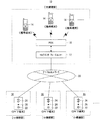
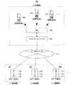
図1は、本発明が適用された駅通信システム10の全体構成を示す図解図である。この図1から分かるように、本実施形態に係る駅通信システム10は、図5に示したのと同様のネットワーク装置としてのマルチインタフェースユニット12と、複数の携帯端末装置14,14,…と、複数のIPドア端末装置16,16,…と、PBX18と、デジタルネットワーク20と、を備えている。そして、それぞれのIPドア端末装置16は、呼び出しボタン22と、音情報出力手段としてのスピーカ24と、音情報検出手段としてのマイクロホン26と、を備えている。ただし、本実施形態においては、個々のIPドア端末装置16がエコーキャンセル機能を搭載しているのではなく、マルチインタフェースユニット12がエコーキャンセル機能を搭載している。そして、このマルチインタフェースユニット12のエコーキャンセル機能によって全てのIPドア端末装置16,16,…について一元的にエコーキャンセルが施される。言い換えれば、マルチインタフェースユニット12から各IPドア端末装置16,16,…に対してネットワーク20越しのエコーキャンセルが実現される。
FIG. 1 is an illustrative view showing an overall configuration of a
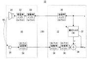
このネットワーク20越しのエコーキャンセルを実現するために、本実施形態におけるマルチインタフェースユニット12は、図2に示すように、送信用バッファ30を備えている。なお、図2は、或るIPドア端末装置16と或る携帯端末装置14との間で通話が行われているときの当該或るIPドア端末装置16とマルチインタフェースユニット12とのエコーキャンセルに関係する部分を概念的に示す図解図である。また、詳しい図示は省略するが、送信用バッファ30は、送信手段としての送信回路を構成する。
In order to realize the echo cancellation over the
この送信用バッファ30を含む送信回路は、相手方のIPドア端末装置16に送信する第1音信号としての音声信号xを例えばUDP(User Datagram Protocol)パケットに符号化し、いわゆるパケット化する。パケット化された音声信号xは、一旦、送信用バッファ30に記憶された後、デジタルネットワーク20を介して、相手方のIPドア端末装置16に送信される。なお、送信用バッファ30は、例えば2パケット分の記憶容量を有しており、この送信用バッファ30に記憶された当該2パケット分の音声信号xは、記憶された順番に従って1パケット分ずつ順次読み出され、送信される。また、マルチインタフェースユニット12は、例えばFIR(Finite
Impulse Response)型の適応フィルタ32を有しており、この適応フィルタ32にも、送信用バッファ30を含む送信回路に入力されるのと同じ(つまりパケット化される前の)音声信号xが入力される。
The transmission circuit including the
Impulse Response) type
相手方のIPドア端末装置16は、調整用バッファ50を有しており、この調整用バッファ50に、マルチインタフェースユニット12からデジタルネットワーク20を介して送信されてくる音声信号xが1パケット分ずつ順次入力され、記憶される。この調整用バッファ50は、デジタルネットワーク20を含む伝送路のゆらぎの影響を吸収するためのものであり、例えば5パケット分の記憶容量を有している。そして、この調整用バッファ50に記憶された5パケット分の音声信号xは、記憶された順番に従って1パケット分ずつ順次読み出され、さらに受信用バッファ52に入力され、詳しくは当該受信用バッファ52を含む受信回路に入力される。この受信用バッファ52を含む受信回路は、これに入力された音声信号xを当該受信用バッファ52に記憶しながら元の状態に復号化する。なお、受信用バッファ52は、例えば3パケット分の記憶容量を有しており、この受信用バッファ52に記憶された当該3パケット分の音声信号xは、記憶された順番に従って1パケット分ずつ順次読み出され、復号化される。そして、復号化された音声信号xは、スピーカ24に入力される。これにより、スピーカ24から当該音声信号xに応じた第1音情報としての音が出力される。
The counterpart IP
このとき、図2に破線の矢印60で示すように、スピーカ24の出力音の一部がマイクロホン26に入力されることで、当該マイクロホン26から出力される音声信号yにエコー成分が現れる。そして、このエコー成分を含む音声信号yは、IPドア端末装置16内に設けられている送信用バッファ54に入力され、詳しくは当該送信用バッファ54を含む送信回路に入力される。この送信用バッファ54を含む送信回路は、マルチインタフェースユニット12に設けられているものと同様のものであり、入力された音声信号yをUDPパケットに符号化し、つまりパケット化する。なお、送信用パケット54は、2パケット分の記憶容量を有している。そして、この送信用バッファ54を含む送信回路によってパケット化された音声信号yは、1パケット分ずつ順次、デジタルネットワーク20を介して、マルチインタフェースユニット12に送信される。
At this time, as indicated by a broken-
マルチインタフェースユニット12は、遅延手段としての調整用バッファ34を有しており、この調整用バッファ34に、IPドア端末装置16からデジタルネットワーク20を介して送信されてくる音声信号yが1パケットずつ順次入力され、記憶される。この調整用バッファ34もまた、IPドア端末装置16に設けられているものと同様、5パケット分の記憶容量を有しており、デジタルネットワーク20を含む伝送路のゆらぎの影響を吸収する作用を奏する。そして、この調整用バッファ34に記憶された5パケット分の音声信号yは、記憶された順番に従って1パケット分ずつ順次読み出され、さらに受信用バッファ36に入力され、詳しくは当該受信用バッファ36を含む受信手段としての受信回路に入力される。
The
受信用バッファ36を含む受信回路は、IPドア端末装置16に設けられているものと同様、これに入力された音声信号yを受信用バッファ36に記憶しながら元の状態に復号化する。なお、受信用バッファ36は、3パケット分の記憶容量を有しており、この受信用バッファ36に記憶された音声信号yは、1パケットずつ順次読み出され、復号化される。そして、復号化された音声信号yは、減算手段としての加算器38に入力される。
The receiving circuit including the receiving
加算器38には、適応フィルタ32による処理後信号uも入力されており、当該加算器38は、この処理後信号uを音声信号yから減算する。そして、この加算器38による減算後の信号、つまり処理後信号uと音声信号yとの差を表す誤差信号eは、図示しない種々の回路を介して、PBX18に送られ、ひいてはIPドア端末装置16の相手方の携帯端末装置14に送られる。
The
併せて、誤差信号eは、適応フィルタ32にフィードバックされる。適応フィルタ32は、この誤差信号eが最小になるように、言い換えれば当該適応フィルタ32による処理後信号uが音声信号yと等価(u=y)になるように、自身のフィルタ係数Wを適宜更新し、いわゆる適応動作する。
In addition, the error signal e is fed back to the
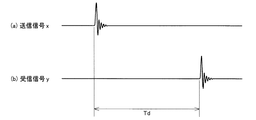
ただし、適応フィルタ32に入力される音声信号x、言わば元の送信信号xと、当該適応フィルタ32による処理後信号uの減算対象となる音声信号y、要するにエコー成分を含む受信信号yと、の間には、図3に示すような位相差Tdがある。この位相差Tdは、主に上述した各バッファ30,50,52,54,34および36による遅延時間に起因し、つまり合計20パケット分の時間に相当する。従って、マルチインタフェースユニット12からIPドア端末装置16に対してデジタルネットワーク20越しのエコーキャンセルを実現するには、この遅延時間(位相差)Tdを考慮する必要がある。
However, the audio signal x input to the
そこで、本実施形態における適応フィルタ32は、自身に入力される送信信号xのうち、現時点から遅延時間Tdを考慮した所定の期間Ti分だけ過去に遡った時点までの部分については、適応処理の対象外とし、この所定期間Ti分だけ過去に遡った時点からさらに自身のタップ長に応じた期間Ta分だけ過去に遡った時点までの部分のみを対象として、適応処理を行う。つまり、適応処理の対象となる部分を絞る。これにより、適応フィルタ32は、適応対象外期間Tiと適応対象期間Taとを足し合わせた期間(=Ti+Ta)分のタップ長を言わば擬似的に有することになり、当該擬似的には現時点から遅延時間Tdよりも長い期間(=Ti+Ta>Td)分だけ過去に遡った当該期間分の送信信号xを適応処理するのと等価な結果を得ることができる。ゆえに、マルチインタフェースユニット12からIPドア端末装置16に対してデジタルネットワーク20越しであっても実用的なエコーキャンセルが可能となる。
Therefore, the
なお、このようなデジタルネットワーク20を有する駅通信システム10においては、上述したゆらぎによって、受信信号yの送信信号xに対する相対的な位相が変化する。従って、適応対象期間Ta(適応フィルタ34のタップ長)については、このゆらぎによる位相の変化分を加味して多少の余裕を持つことが必要とされる。また、ゆらぎによって、或る時点から遅延時間Tdに相当する期間が経過する前に(例えば図3(b)において左側寄りに)、当該或る時点に送信(送信用バッファ30を含む送信回路に入力)された送信信号xのエコー成分を含む受信信号yが現れる場合もあるので、適応対象外期間Tiについては、当該遅延時間Tdよりも小さめ(Ti<Td)に設定されるのが、望ましい。具体的には、次の通りである。
Note that, in the station a
即ち、本実施形態における本線としてのデジタルネットワーク20は、光回線等の広帯域の伝送路であり、例えば128kbps(キロビット毎秒)超の容量を持つ。そして、このデジタルネットワーク20とマルチインタフェースユニット12とを結ぶ線路もまた、同様の広帯域伝送路である。これに対して、デジタルネットワーク20とそれぞれのIPドア端末装置16とを結ぶ支線については、当該それぞれのIPドア端末装置16の設置環境によって、広帯域の伝送路であるものもあれば、容量が64kbps未満の狭帯域の伝送路であるものもあり、さらには、64kbps以上かつ128kbps以下の中帯域の伝送路であるものもある。マルチインタフェースユニット12は、相手方のIPドア端末装置16(支線)の伝送路容量に合わせてパケット通信を行う。例えば、当該相手方のIPドア端末装置16の伝送路容量が広帯域である場合には、広帯域でパケット通信を行い、相手方のIPドア端末装置16の伝送路容量が中帯域である場合には、中帯域でパケット通信を行う。そして、相手方のIPドア端末装置16の伝送路容量が狭帯域である場合には、狭帯域でパケット通信を行う。それぞれのIPドア端末装置16の伝送路容量がいずれであるのかは、マルチインタフェースユニット12側で予め設定(認識)されているので、このような伝送路容量の自動的な切り換えが可能となる。
That is, the
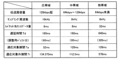
ここで、例えば、広帯域でパケット通信が行われる場合には、図4に示すように、送信信号xおよび受信信号yのサンプリング周波数が、16kHzに設定される。そして、1パケット当たりのデータ量が、8ms相当分とされ、ゆえに、遅延時間Tdは、20パケット分の160msとなる。このうち、IPドア端末装置16側の調整用バッファ50とマルチインタフェースユニット12側の調整用バッファ34とによる言わば調整遅延分は、10パケット分の80msである。そして、適用対象期間Taは、適応フィルタ34のタップ長によって決まり、例えば32msとされている。一方、適応対象外期間Tiは、適用対象期間Taと遅延時間Tdと上述したゆらぎとを加味して定められ、経験や実験結果から、例えば134.375msに設定される。なお、この適用対象外期間Tiは、ゆらぎの程度を含む種々の状況に応じて任意に変更可能とされている。
Here, for example, if the wideband packet communication is performed, as shown in FIG. 4, the sampling frequency of the transmission signal x and the received signal y is set to 16 kHz. The data amount per packet is set to be equivalent to 8 ms. Therefore, the delay time Td is 160 ms for 20 packets. Of these, the adjustment delay due to the
また、中帯域でパケット通信が行われる場合には、サンプリング周波数が、例えば広帯域の場合の半分の8kHzに設定される。その一方で、1パケット当たりのデータ量は、広帯域の場合と同じ8ms相当分とされ、ゆえに、遅延時間Tdもまた、広帯域の場合と同じ160msとなる。そして、このうちの調整遅延分は、80msである。さらに、適応対象期間Taは、上述の如く適応フィルタ34のタップ長によって決まるので、サンプリング周波数が8kHzであることから、128msとなる。これに応じて、適応対象外期間Tiは、例えば112.5msとされる。
When packet communication is performed in the middle band, the sampling frequency is set to 8 kHz, which is half of that in the wide band, for example. On the other hand, the amount of data per packet is equivalent to 8 ms, which is the same as that in the wideband, and therefore the delay time Td is also 160 ms, which is the same as in the wideband. Of these, the adjustment delay is 80 ms. Furthermore, since the adaptation target period Ta is determined by the tap length of the
そして、狭帯域でパケット通信が行われる場合、サンプリング周波数は、例えば中帯域の場合と同じ8kHzに設定される。その一方で、1パケット当たりのデータ量は、中帯域の場合の4倍の32ms相当分とされる。ゆえに、遅延時間Tdは、20パケット分の640msとなり、このうちの調整遅延分は、10パケット分の320msとなる。また、適応対象期間Taは、中帯域の場合と同じ128msとなり、適応対象外期間Tiは、例えば576msとされる。 When packet communication is performed in a narrow band, the sampling frequency is set to 8 kHz, which is the same as that in the middle band, for example. On the other hand, the amount of data per packet is equivalent to 32 ms, which is four times that of the middle band. Therefore, the delay time Td is 640 ms for 20 packets, and the adjustment delay is 320 ms for 10 packets. Further, the adaptation target period Ta is 128 ms, which is the same as that in the middle band, and the non-adaptation period Ti is, for example, 576 ms.
これらのサンプリング周波数を含むパラメータは、飽くまでも一例であり、これに限定されない。つまり、状況に応じて適宜に定められるのが、望ましい。 The parameters including these sampling frequencies are merely examples, and are not limited thereto. That is, it is desirable that it is determined appropriately according to the situation.
以上のように、本実施形態によれば、マルチインタフェースユニット12から全てのIPドア端末装置16,16,…に対してネットワーク20越しのエコーキャンセルが実現される。従って、それぞれのIPドア端末装置16,16,…ごとにエコーキャンセル機能を搭載する必要はない。ゆえに、当該IPドア端末装置16,16,…を含む駅通信システム10全体の構成を簡素化することができ、併せて、その価格を低減することができる。このことは、IPドア端末装置16…の数が多いほど、顕著になる。
As described above, according to the present embodiment, echo cancellation through the
なお、本実施形態においては、マルチインタフェースユニット12側の送信用バッファ30,調整用バッファ34および受信用バッファ36の各記憶容量を、それぞれ2パケット分,5パケット分および3パケット分としたが、これに限らない。これらのパケット数は、エコーキャンセル機能が適切に働くことを含め良好な通話が実現される範囲内(例えば過度な遅延等が生じない範囲内)で適宜に設定すればよい。このことは、IPドア端末装置16側の各バッファ50,52および54についても、同様である。また、送信信号xが経由する言わば送信側(往路側)のバッファ30,50および52の合計パケット数と、受信信号yが経由する受信側(復路側)のバッファ54,34および36の合計パケット数とを、互いに同じとしたが、相違してもよい。ただし、送受信間の通信バランスを考慮すれば、両者は同じであるのが、望ましい。さらに、IPドア端末装置16側の調整用バッファ50についても、結果的に、マルチインタフェースユニット12側の調整用バッファ34と同様の遅延手段として作用するが、この遅延手段として作用する別の調整用バッファをマルチインタフェースユニット12の送信側に設けてもよい。いずれにしても、エコーキャンセル機能が適切に働くことを含め良好な通話が実現されるように、各条件を適宜に設定することが、肝要である。
In this embodiment, the storage capacities of the
また、本実施形態においては、駅通信システム10を構成するマルチインタフェースユニット12に本発明を適用する場合を例に挙げて説明したが、これに限らない。即ち、駅通信システム10以外の用途にも当該マルチインタフェースユニット12を適用することができるし、当該マルチインタフェースユニット12以外の装置にも本発明を適用することができる。つまり、互いに同じ空間に設けられた音情報出力手段および音情報検出手段がデジタルネットワークを介して接続される装置であれば、本発明を適用することができる。そして、デジタルネットワークは、有線に限らず、無線であってもよい。
In the present embodiment, the case where the present invention is applied to the
さらに、本実施形態で例示したエコーキャンセルは一種のシステム同定であるので、当該エコーキャンセルに限らず、例えば単にIPドア端末装置16側の空間の伝達関数を同定するのに、本発明を適用してもよい。これを応用すれば、遠隔地にあるコンサートホール等の任意の空間の伝達関数をデジタルネットワーク越しに同定することができ、ひいては当該任意の空間のイコライジング操作等をデジタルネットワーク越しに行うことができる。
Further, since the echo cancellation exemplified in the present embodiment is a kind of system identification, the present invention is not limited to the echo cancellation, and the present invention is applied to simply identify the transfer function of the space on the IP
10 駅通信システム
12 マルチインタフェースユニット
16 IPドア端末装置
20 デジタルネットワーク
24 スピーカ
26 マイクロホン
32 適応フィルタ
34 調整用バッファ
DESCRIPTION OF
Claims (5)
上記デジタルネットワークを介して上記第1音信号を通信中の上記相手方装置の上記音情報出力手段に送信する送信手段と、
上記デジタルネットワークを介して上記第2音信号を上記通信中の相手方装置の上記音情報検出手段から受信する受信手段と、
上記第1音信号が入力されると共に上記通信中の相手方装置における上記第1音情報の上記音情報検出手段への回り込み成分であるエコー成分を模擬した模擬信号を該第1音信号に基づいて生成する適応フィルタ手段と、
上記送信手段から上記通信中の相手方装置に送信される上記第1音信号および上記受信手段によって該通信中の相手方装置から受信される上記第2音信号の一方または両方を遅延させる遅延手段と、
を具備し、
上記適応フィルタ手段は、自身に入力される上記第1音信号のうち、現時点から上記遅延手段による遅延時間を考慮した所定期間分だけ過去に遡った時点までの部分について、適応処理の対象外とし、該所定期間分だけ過去に遡った時点からさらに自身のタップ長に応じた期間分だけ過去に遡った時点までの特定部分に基づいて、該適応処理を行い、
上記デジタルネットワークを介しての上記通信中の相手方装置との間の上記第1音信号および上記第2音信号の伝送路の容量に応じて上記遅延時間と上記所定期間と上記タップ長に応じた期間とを含むパラメータを設定するパラメータ設定手段をさらに備える、
ネットワーク装置。 And sound information output means for outputting a first sound information corresponding to the first sound signal, second detecting the second sound information present in the provided by our Ri該 space in the same space as the sound information output means A plurality of counterpart devices each having sound information detecting means for generating a second sound signal according to sound information, are network devices connected via a digital network,
Transmitting means for transmitting the first sound signal to the sound information output means of the counterpart device in communication via the digital network;
Receiving means for receiving the second sound signal from the sound information detecting means of the counterpart device in communication via the digital network;
Based on the first sound signal, a simulated signal simulating an echo component that is a wraparound component of the first sound information to the sound information detecting means in the counterpart device in communication with the first sound signal is input . Adaptive filter means to generate ,
Delay means for delaying one or both of the second sound signal received from the counterpart device in the communication by said first sound signal and said receiving means is transmitted to the opposite device in the communication from the transmission means,
Comprising
The adaptive filter means excludes the portion of the first sound signal input to itself from the present time to a time point that has been traced back by a predetermined period considering the delay time by the delay means. , based on the specific parts up to the point of going back to the past by period further in accordance with the tap length of itself from the timing predated only past the predetermined period component performs the adaptation process,
According to the delay time, the predetermined period, and the tap length according to the capacity of the transmission path of the first sound signal and the second sound signal with the counterpart device in communication via the digital network A parameter setting means for setting a parameter including a period;
Network device.
請求項1に記載のネットワーク装置。The network device according to claim 1.
請求項1または2に記載のネットワーク装置。 The delay means delays both the first sound signal and the second sound signal over the same time;
The network device according to claim 1 or 2 .
請求項1ないし3のいずれかに記載のネットワーク装置。 The predetermined period can be arbitrarily changed.
The network device according to claim 1.
請求項1ないし4のいずれかに記載のネットワーク装置。 Subtracting means for subtracting the simulation signal from the second sound signal;
The network device according to claim 1.
Priority Applications (1)
| Application Number | Priority Date | Filing Date | Title |
|---|---|---|---|
| JP2009286096A JP5367554B2 (en) | 2009-12-17 | 2009-12-17 | Network equipment |
Applications Claiming Priority (1)
| Application Number | Priority Date | Filing Date | Title |
|---|---|---|---|
| JP2009286096A JP5367554B2 (en) | 2009-12-17 | 2009-12-17 | Network equipment |
Publications (2)
| Publication Number | Publication Date |
|---|---|
| JP2011130145A JP2011130145A (en) | 2011-06-30 |
| JP5367554B2 true JP5367554B2 (en) | 2013-12-11 |
Family
ID=44292252
Family Applications (1)
| Application Number | Title | Priority Date | Filing Date |
|---|---|---|---|
| JP2009286096A Active JP5367554B2 (en) | 2009-12-17 | 2009-12-17 | Network equipment |
Country Status (1)
| Country | Link |
|---|---|
| JP (1) | JP5367554B2 (en) |
Families Citing this family (2)
| Publication number | Priority date | Publication date | Assignee | Title |
|---|---|---|---|---|
| JP5745475B2 (en) * | 2012-08-08 | 2015-07-08 | 日本電信電話株式会社 | Echo cancellation method, system and devices |
| JP6396780B2 (en) * | 2014-12-10 | 2018-09-26 | 日本電信電話株式会社 | Echo cancellation device, base device, communication system, and echo cancellation method |
Family Cites Families (2)
| Publication number | Priority date | Publication date | Assignee | Title |
|---|---|---|---|---|
| JP2004254022A (en) * | 2003-02-19 | 2004-09-09 | Mitsubishi Electric Corp | IP network communication device |
| JP4894368B2 (en) * | 2006-06-16 | 2012-03-14 | 沖電気工業株式会社 | Echo canceller |
-
2009
- 2009-12-17 JP JP2009286096A patent/JP5367554B2/en active Active
Also Published As
| Publication number | Publication date |
|---|---|
| JP2011130145A (en) | 2011-06-30 |
Similar Documents
| Publication | Publication Date | Title |
|---|---|---|
| US20090046866A1 (en) | Apparatus capable of performing acoustic echo cancellation and a method thereof | |
| US8462675B2 (en) | Echo mitigation in the presence of variable delays due to adaptive jitter buffers | |
| EP2229011B1 (en) | Hearing assistance devices with echo cancellation | |
| US20160050491A1 (en) | Reversed Echo Canceller | |
| US7366118B2 (en) | Echo cancellation | |
| WO2016096339A1 (en) | Delay estimation for echo cancellation using ultrasonic markers | |
| Ogunfunmi et al. | Speech over VoIP networks: Advanced signal processing and system implementation | |
| CA3022058A1 (en) | Cloud-based acoustic echo canceller | |
| US10540984B1 (en) | System and method for echo control using adaptive polynomial filters in a sub-band domain | |
| US20120140918A1 (en) | System and method for echo reduction in audio and video telecommunications over a network | |
| JP5367554B2 (en) | Network equipment | |
| US8666058B2 (en) | Time domain adaptive filter bank for network echo reduction or cancellation | |
| WO2007068166A1 (en) | Electricity echo elimination device and method | |
| JP5963077B2 (en) | Telephone device | |
| JP5745475B2 (en) | Echo cancellation method, system and devices | |
| Hasbullah et al. | The effect of echo delay on voice quality in VoIP network | |
| CN102739287A (en) | Echo cancelling method based on self-adaptive time delay estimation | |
| JP4576847B2 (en) | Echo canceller control device and voice communication device | |
| JP4346414B2 (en) | Signal processing device, computer program | |
| JP5666063B2 (en) | Telephone device | |
| JP5219000B2 (en) | Echo canceller and control method of echo canceller | |
| JP5204378B2 (en) | Terminal device and echo canceling method | |
| Rassameeroj et al. | Echo cancellation in voice over ip | |
| JP2009302984A (en) | Voice communication apparatus and voice communication method | |
| Dinh Van et al. | Removing Long Echo Delay Using Combination of Jitter Buffer and Adaptive Filter |
Legal Events
| Date | Code | Title | Description |
|---|---|---|---|
| A621 | Written request for application examination |
Free format text: JAPANESE INTERMEDIATE CODE: A621 Effective date: 20111110 |
|
| A977 | Report on retrieval |
Free format text: JAPANESE INTERMEDIATE CODE: A971007 Effective date: 20130221 |
|
| A131 | Notification of reasons for refusal |
Free format text: JAPANESE INTERMEDIATE CODE: A131 Effective date: 20130226 |
|
| A521 | Request for written amendment filed |
Free format text: JAPANESE INTERMEDIATE CODE: A523 Effective date: 20130426 |
|
| TRDD | Decision of grant or rejection written | ||
| A01 | Written decision to grant a patent or to grant a registration (utility model) |
Free format text: JAPANESE INTERMEDIATE CODE: A01 Effective date: 20130903 |
|
| A61 | First payment of annual fees (during grant procedure) |
Free format text: JAPANESE INTERMEDIATE CODE: A61 Effective date: 20130911 |
|
| R150 | Certificate of patent or registration of utility model |
Free format text: JAPANESE INTERMEDIATE CODE: R150 Ref document number: 5367554 Country of ref document: JP Free format text: JAPANESE INTERMEDIATE CODE: R150 |
|
| R250 | Receipt of annual fees |
Free format text: JAPANESE INTERMEDIATE CODE: R250 |
|
| R250 | Receipt of annual fees |
Free format text: JAPANESE INTERMEDIATE CODE: R250 |
|
| R250 | Receipt of annual fees |
Free format text: JAPANESE INTERMEDIATE CODE: R250 |
|
| R250 | Receipt of annual fees |
Free format text: JAPANESE INTERMEDIATE CODE: R250 |
|
| R250 | Receipt of annual fees |
Free format text: JAPANESE INTERMEDIATE CODE: R250 |
|
| R250 | Receipt of annual fees |
Free format text: JAPANESE INTERMEDIATE CODE: R250 |
|
| R250 | Receipt of annual fees |
Free format text: JAPANESE INTERMEDIATE CODE: R250 |
|
| R250 | Receipt of annual fees |
Free format text: JAPANESE INTERMEDIATE CODE: R250 |
|
| R250 | Receipt of annual fees |
Free format text: JAPANESE INTERMEDIATE CODE: R250 |
|
| R250 | Receipt of annual fees |
Free format text: JAPANESE INTERMEDIATE CODE: R250 |
|
| R250 | Receipt of annual fees |
Free format text: JAPANESE INTERMEDIATE CODE: R250 |