JP5367541B2 - Abnormality notification device - Google Patents
Abnormality notification device Download PDFInfo
- Publication number
- JP5367541B2 JP5367541B2 JP2009261052A JP2009261052A JP5367541B2 JP 5367541 B2 JP5367541 B2 JP 5367541B2 JP 2009261052 A JP2009261052 A JP 2009261052A JP 2009261052 A JP2009261052 A JP 2009261052A JP 5367541 B2 JP5367541 B2 JP 5367541B2
- Authority
- JP
- Japan
- Prior art keywords
- abnormality
- abnormality detection
- output
- signal
- audio information
- Prior art date
- Legal status (The legal status is an assumption and is not a legal conclusion. Google has not performed a legal analysis and makes no representation as to the accuracy of the status listed.)
- Active
Links
Images


Landscapes
- Details Of Television Systems (AREA)
- Alarm Systems (AREA)
Abstract
Description
本発明は、異常報知装置に関し、特に電源手段の異常を音声によって報知するものに関する。 The present invention relates to an abnormality notification device, and more particularly to a device that notifies an abnormality of a power supply means by voice.
従来、電源手段の異常を音声によって報知するものとしては、例えば特許文献1に開示されているようなものがある。特許文献1の技術では、屋根等に設置された太陽電池が発生させた直流電力を、屋根裏等に設置されたパワーコンディショナーが交流電力に変換する電源システムにおいて、このシステムの各所に温度センサ、電流センサ、電圧センサなどの各種検知手段が設けられ、システムの異常をこれらの検知手段で常時監視している。検知手段が異常を検知すると、異常を検知した旨が居間等に設置された制御部に報告される。制御部は、報告された異常の内容を検討して、異常の内容及びその対象を指し示す音声データを作成し、スピーカから拡声している。
2. Description of the Related Art Conventionally, for example, there is one disclosed in
このような異常報知装置では、1つの家屋の屋根裏にパワーコンディショナーが設置され、制御部が居間に設置されているので、両者の距離は比較的近く、検知手段からの検知信号を制御部に伝送することは容易である。しかし、このような異常報知装置を、例えば山の頂上等に設置されるテレビジョン放送用の再送信装置の電源手段と、この再送信装置からかなり離れた位置にある監視者の位置に制御部を設けた場合、検出信号を伝送するためのケーブルを長い距離にわたって敷設する必要がある。また、検出手段の種類によっては同時に異常を検出することがある。例えば検出手段として停電検出手段と、電源の出力電圧の検出手段とを備えている場合、停電が生じたことにより、電源の出力電圧も発生していないので、停電検出手段と出力電圧の検出手段とが同時に異常を検出する。このように同時に複数の異常が生じた場合の対処については、特許文献1はなんら示していない。
In such an abnormality notification device, since the power conditioner is installed in the attic of one house and the control unit is installed in the living room, the distance between the two is relatively short, and the detection signal from the detection means is transmitted to the control unit. It's easy to do. However, such an abnormality notification device, for example, the power supply means of a television broadcast retransmitting device installed at the top of a mountain or the like, and a control unit at a position of a supervisor far away from the retransmitting device. When a cable is provided, it is necessary to lay a cable for transmitting a detection signal over a long distance. Also, depending on the type of detection means, an abnormality may be detected at the same time. For example, when a power failure detection means and a power supply output voltage detection means are provided as detection means, the power failure output means and the output voltage detection means are not generated due to the occurrence of a power failure. And detect abnormalities at the same time. Thus,
本発明は、離れた位置にケーブルを敷設する必要が無く、しかも複数の異常が生じた場合に優先度の高い異常について音声出力する異常報知装置を提供することを目的とする。 SUMMARY OF THE INVENTION An object of the present invention is to provide an abnormality notification device that does not need to lay a cable at a distant position and that outputs a sound regarding an abnormality having a high priority when a plurality of abnormalities occur.
本発明の一態様の異常報知装置は、再送信システムに使用されている。再送信システムは、放送局からのテレビジョン放送信号を受信可能な場所に設置され、受信アンテナで受信した前記テレビジョン放送信号を処理する前置処理手段と、前記前置処理手段から離れた位置に設置され、前記前置処理手段から出力された処理済みのテレビジョン放送信号が伝送路を介して供給され、再送信アンテナから前記テレビジョン放送信号の難視聴地域に向けて再送信される再送信装置とを、有している。前記前置処理手段は、異なる複数の異常検出手段を備える電源手段を有している。前記前置処理手段には、制御手段と、送信手段とが設けられている。制御手段は、前記複数の検出手段からの異常検出信号が供給され、複数の異常検出信号が同時に供給された場合、前記複数の異常検出信号のうち1つを予め定めた優先度に従って選択し、既に出力されている音声情報が不存在の場合、前記選択された異常検出信号に対応する音声情報をループ出力し、既に出力されている音声情報が存在する場合、出力されている音声情報の1ループの出力後に前記選択された異常検出信号に対応する音声情報をループ出力する。送信手段は、制御手段からループ出力された前記音声情報で、市販の受信手段で受信可能な周波数の搬送波を変調して無線信号を生成する。前記再送信装置には、前記送信手段からの前記無線信号が前記伝送路を介して伝送され、伝送された前記無線信号を送信する送信アンテナが設けられている。The abnormality notification device of one aspect of the present invention is used in a retransmission system. The re-transmission system is installed in a place where a television broadcast signal from a broadcasting station can be received, and a pre-processing means for processing the television broadcast signal received by a receiving antenna, and a position away from the pre-processing means The processed television broadcast signal output from the preprocessing means is supplied via a transmission path, and is retransmitted from the retransmission antenna toward the difficult viewing area of the television broadcast signal. A transmission device. The pre-processing unit includes a power source unit including a plurality of different abnormality detection units. The pre-processing means is provided with a control means and a transmission means. The control means is supplied with abnormality detection signals from the plurality of detection means, and when a plurality of abnormality detection signals are supplied simultaneously, selects one of the plurality of abnormality detection signals according to a predetermined priority, When there is no audio information already output, the audio information corresponding to the selected abnormality detection signal is output as a loop. When there is audio information already output, 1 of the output audio information After outputting the loop, the audio information corresponding to the selected abnormality detection signal is output as a loop. The transmitting means modulates a carrier wave having a frequency that can be received by a commercially available receiving means with the audio information output as a loop from the control means, and generates a radio signal. The retransmission apparatus is provided with a transmission antenna that transmits the radio signal transmitted from the transmission unit via the transmission path and transmits the transmitted radio signal.
前記送信手段は、前記異常検出信号が前記制御手段に供給されたときに動作を開始するものとできる。このように構成すると、異常が検出されたときのみに、送信手段が動作するので、通常時での消費電力を抑えることができる。 The transmission means may start to operate when the abnormality detection signal is supplied to the control means. If comprised in this way, since a transmission means will operate | move only when abnormality is detected, the power consumption in normal time can be suppressed.
前記所定周波数は、FM受信機によって受信可能な周波数であって、前記搬送波の変調はFM変調とすることができる。このように構成すると、専用の受信機を特別に設置する必要が無く、市販されているFM受信機によって異常が生じていることを知ることができる。 The predetermined frequency may be a frequency that can be received by an FM receiver, and the modulation of the carrier wave may be FM modulation. If comprised in this way, it is not necessary to install a special receiver specially, and it can know that abnormality has arisen with the FM receiver marketed.
以上のように、本発明による異常報知装置によれば、複数の異常が生じた場合に優先度の高い異常について音声出力することができ、しかもその報知は、異常報知装置の設置場所から離れた位置でなんら特別の設備を準備しなくても知ることができる。 As described above, according to the abnormality notification device according to the present invention, when a plurality of abnormalities occur, it is possible to output a voice regarding a high priority abnormality, and the notification is separated from the installation location of the abnormality notification device. You can know the location without preparing any special equipment.
本発明の1実施形態の異常報知装置は、図2に示すように、テレビジョン放送用の再送信手段、例えば再送信装置2に設けられている。再送信装置2は、テレビジョン放送の難視聴地域の近傍にある高所、例えば山の近傍の平地に設置されている。この山の頂上には前置処理手段、例えばヘッドアンプ装置4が設置されている。ヘッドアンプ装置4では、受信アンテナ5で受信した放送局からのテレビジョン放送信号が増幅等の処理がなされ、伝送路、例えば同軸ケーブルまたは光ファイバー6を介して再送信装置2に伝送される。再送信装置2は、伝送されたテレビジョン放送信号等に増幅等の処理をして、これを送信アンテナ10によって難視聴地域に向けて再放射する。なお、図2では、ヘッドアンプ装置4に対して1台の再送信装置2を示したが、ヘッドアンプ装置4に対して分岐分配手段を介して複数台の再送信装置2が設けられることもある。
As shown in FIG. 2, the abnormality notification device according to one embodiment of the present invention is provided in a retransmission means for television broadcasting, for example, the
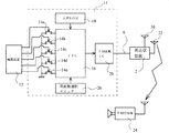
ヘッドアンプ装置4は、図1に示すように、電子機器用の電源手段、例えば電源装置12を有している。この電源装置12は、例えば商用交流電源からの交流電力を整流、平滑して、直流電力に変換する交流−直流変換ユニットを有し、この交流−直流変換ユニットからの直流電力をヘッドアンプ装置4の各構成部品に供給している。また、この電源装置12は、無停電電源ユニットも備えており、商用交流電源が停電したような場合に、一定の時間にわたって無停電電源ユニットからヘッドアンプ装置4の各構成部品に直流電力を供給する。無停電電源ユニットは、内蔵バッテリー及び外付けバッテリーを備え、さらに、これら内蔵バッテリー及び外付けバッテリーを、交流−直流変換ユニットから得た直流電力によって充電するための充電回路も備えている。
As shown in FIG. 1, the
この電源装置12には、複数、例えば5つの異なる検出手段が設けられている。例えば無停電電源ユニットが備える内蔵バッテリーに異常が発生しているか否かを検出する内蔵バッテリー異常検出器Aが設けられ、無停電電源ユニットが備える外付けバッテリーに異常が発生しているか否かを検出する外付けバッテリー異常検出器Bが設けられている。また、これら内蔵バッテリー及び外付けバッテリーに充電するための充電回路に異常が発生しているか否かを検出する充電回路異常検出器Cが設けられている。また、電源装置12の設置場所において停電が発生しているか否かを検出する停電検出器Dが設けられている。更に、交流−直流変換ユニットに異常が発生しているか否かを検出する交流−直流変換ユニット異常検出器Eが設けられている。なお、交流−直流変換ユニットの異常検出器としては、出力電圧が予め定めた基準出力電圧よりも低い電圧しか出力していないことを異常として検出する出力電圧異常検出器や、出力電流が予め定めた基準出力電流よりも低い電流しか出力していないことを異常として検出する出力電流異常検出器や、入力電圧が予め定めた基準入力電圧よりも低いことを異常として検出する入力電圧異常検出器や、入力電流が予め定めた基準入力電流よりも低いことを異常として検出する入力電流異常検出器を個別に設けることもできる。
The
上記の各検出器A乃至Eは、それぞれに対応する接点14a、14b、14c、14d、14eを有している。これら接点14a乃至14eの一端は、制御手段、例えばCPU16に接続され、他端は、基準電位点、例えば接地電位点に接続されている。そして、各接点14a乃至14eは、対応する検出器A乃至Eが異常を検出していないときオフであり、各検出器A乃至Eのうち異常を検出したものがあると、その異常を検出した検出器に対応する接点がオンされる。例えば充電回路異常検出器Cが異常を検出すると、接点14cが閉じられる。これによって、CPU16には、接地電位である異常検出信号が供給される。
Each of the detectors A to E has
CPU16には、音声発生手段、例えば音声ROM18が設けられている。音声ROM18には、各検出器A乃至Eが検出した異常を表す音声情報、例えば音声信号が記憶されている。例えば、検出器Aの異常検出に対応して、「内蔵バッテリーに異常が発生しています。」との音声信号が記憶され、検出器Bの異常検出に対応して、「外付けバッテリーに異常が発生しています。」との音声信号が記憶され、検出器Cの異常検出に対応して、「充電回路に異常が発生しています。」との音声信号が記憶され、検出器Dの異常検出に対応して、「設置場所で停電が発生しています。」との音声信号が記憶され、検出器Eでの異常検出に対応して、「交流−直流変換ユニットに異常が発生しています。」との音声信号が記憶されている。
The
CPU16は、後述するように、各接点14a乃至14eのうち閉じられているもののうち優先度の高いものに対応する音声信号を選択し、送信手段、例えばFM変調IC20に供給する。FM変調IC20は、搬送波を音声信号でFM変調し、そのFM変調信号を再送信装置2に設けられた送信アンテナ22に伝送路6を介して供給し、これから送信する。このFM変調信号を市販されているFM受信機24で受信することができる周波数帯のうち空き周波数とするために、搬送波周波数は、CPU16に接続されている周波数選択スイッチ26によって決定される。FM受信機24は、例えば再送信装置2が設置されている場所から離れた位置にある監視所に設置されている。
As will be described later, the
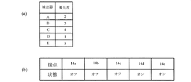
CPU16は、図3(a)に示すように、各検出器A乃至Eに対する優先度が予め定められたテーブルを記憶している。この実施形態では、検出器Dによる停電検出が最も優先度が高く、検出器Aによる内蔵バッテリーの異常検出、検出器Eによる交流−直流変換ユニットの異常検出、検出器Cによる充電回路の異常検出、検出器Bによる外付けバッテリーの異常検出の順に優先度が低く設定されている。
As shown in FIG. 3A, the
このようにCPU16、音声ROM18、FM変調IC20、周波数選択スイッチ26によって異常報知装置11が構成されている。
As described above, the abnormality notification device 11 is configured by the
CPU16は、例えば図4に示すようなフローチャートに従って処理を行う。この処理は、各接点14a乃至14eのうちいずれかが閉じられたことにより開始される。この処理では、まず、各接点14a乃至14eのオン/オフの状態を読み込む(ステップS2)。これによって、例えば図3(b)に示すように、CPU16は各接点14a乃至14eのオン/オフ状態を記憶手段、例えばCPU16に付属するメモリに記憶する。このとき、異常の種類によって複数の接点が同時にオンとなることがある。例えば停電が生じると、交流−直流変換ユニットも出力を発生しないので、停電を検出する検出器Dと、交流−直流変換ユニットの異常を検出する検出器Eとが、異常を検出し、接点14d、14eがオンとなる。或いは、既に異常が検出されていて、これに加えて新たに異常が検出されることもある。例えば、先に内蔵バッテリーの異常が検出されている状態において、さらに充電回路の異常が検出されることがある。
The
次に、CPU16は、オンとなっている接点のうち、優先度が最も高いものを、図3(a)に示すテーブルを参照して決定する(ステップS4)。例えば、上記のように接点14dと14eとがオンとなっている場合、優先度が高い接点14dを選択する。なお、オンとなっている接点が1つの場合には、そのオンとなっている接点がそのまま選択される。
Next, the
続いて、既に出力されている音声があるか判断する(ステップS6)。この判断の答えがノーの場合、選択された接点に対応する音声信号をFM変調IC20にループ出力し、即ち繰り返し供給し、同時にFM変調IC20を動作させ、音声出力していることを記憶し、この処理を終了する(ステップS8)。周波数選択スイッチ26によって選択された周波数の搬送波が選択された音声信号でFM変調されて、FM変調信号が生成され、このFM変調信号が伝送路6を介して再送信装置2に設けた送信アンテナ22に供給され、この送信アンテナ22から送信される。今まで、FM変調信号の生成が行われていない間、FM変調IC20は動作して無く、初めて音声信号が供給されたときに、FM変調IC20が動作を開始する。これによって、異常の無いときには、ヘッドアンプ装置4のFM変調IC20では電力が消費されず、ヘッドアンプ装置4の消費電力を抑えることができる。また、音声信号はループ出力されているので、監視者はFM受信機24で常に受信している必要が無く、適当な時間をおいてFM受信機24で受信することによって異常が発生していることを知ることができる。
Subsequently, it is determined whether there is a voice that has already been output (step S6). If the answer to this determination is no, the audio signal corresponding to the selected contact is loop-outputted to the FM modulation IC 20, that is, repeatedly supplied, and at the same time, the FM modulation IC 20 is operated to store the audio output, and This process is terminated (step S8). The carrier wave of the frequency selected by the
ステップS6の判断の答えがイエスの場合、既になんらかの異常を報知するためのFM変調信号がFM変調IC20から出力されているので、現在出力されている音声信号の1ループの終了後に、選択された接点に対応する音声信号をFM変調IC20にループ出力し、音声出力していることを記憶し(ステップS10)、この処理を終了する。従って、既になんらかの異常が検知され、その異常に対応する音声信号に基づくFM変調信号が送信されている状態で、今までの異常よりも優先度の高い異常が発生していると、そのことが繰り返し報知される。 If the answer to the determination in step S6 is yes, since the FM modulation signal for notifying some abnormality has already been output from the FM modulation IC 20, it has been selected after the end of one loop of the currently output audio signal. An audio signal corresponding to the contact is output as a loop to the FM modulation IC 20 to store that the audio is output (step S10), and this process is terminated. Therefore, if an abnormality having a higher priority than the conventional abnormality has occurred in the state where some abnormality has already been detected and the FM modulation signal based on the audio signal corresponding to the abnormality has been transmitted. Repeatedly informed.
ステップS4において選択された接点が、既に選択されている接点と同じものである場合や、既に選択されている接点よりも優先度が低いものである場合には、ステップS10では、先に選択された音声信号と同じ音声信号がFM変調IC20に供給される。 If the contact selected in step S4 is the same as the contact already selected, or if the priority is lower than the contact already selected, it is selected first in step S10. The same audio signal as the received audio signal is supplied to the FM modulation IC 20.
上記の実施形態において、ヘッドアンプ装置4及び再送信装置2にそれぞれ異常報知装置11を設け、ヘッドアンプ装置4の異常報知装置11のFM変調IC20の出力を伝送路6を介して再送信装置2の送信アンテナ22に供給し、再送信装置2の異常報知装置の11のFM変調IC20の出力を送信アンテナ22に供給して、ヘッドアンプ装置4及び再送信装置2の電源装置の異常を報知するようにすることもできる。この場合、ヘッドアンプ装置4のFM変調IC20のFM変調信号と再送信装置2のFM変調IC20のFM変調信号との周波数は異ならせる。
In the above embodiment , the abnormality notification device 11 is provided in each of the
上記の実施形態では、CPU16は図4に示すような処理を行ったが、これに限ったものではなく、例えば接点14a乃至14eのうちいずれかがオンになるごとに次のような処理を行うこともできる。即ち、或る接点がオンになると、ステップS6のように既に出力されている音声があるか判断し、その答えがノーの場合、ステップS8を実行して、この処理を終了する。ステップS6の判断の答えがイエスの場合、既に出力されている音声信号に対応する接点よりも、今回オンされた接点の優先度が高いか判断し、その答えがイエスの場合には、今回オンされた接点に対応する音声信号をFM変調IC20に供給してステップS10と同様な処理をし、ノーの場合には、そのまま処理を終了する。
In the above embodiment, the
12 電源装置(電源手段)
16 CPU(制御手段)
20 FM変調IC(送信手段)
12 Power supply (power supply means)
16 CPU (control means)
20 FM modulation IC (transmission means)
Claims (3)
前記前置処理手段は、異なる複数の異常検出手段を備える電源手段を有し、
前記前置処理手段には、
前記複数の検出手段からの異常検出信号が供給され、複数の異常検出信号が同時に供給された場合、前記複数の異常検出信号のうち1つを予め定めた優先度に従って選択し、既に出力されている音声情報が不存在の場合、前記選択された異常検出信号に対応する音声情報をループ出力し、既に出力されている音声情報が存在する場合、出力されている音声情報の1ループの出力後に前記選択された異常検出信号に対応する音声情報をループ出力する制御手段と、
制御手段からループ出力された前記音声情報で、市販の受信手段で受信可能な周波数の搬送波を変調して無線信号を生成する送信手段とが、
設けられ、前記再送信装置には、前記送信手段からの前記無線信号が前記伝送路を介して伝送され、伝送された前記無線信号を送信する送信アンテナが設けられている異常報知装置。 Installed in a place where a television broadcast signal from a broadcasting station can be received, pre-processing means for processing the television broadcast signal received by a receiving antenna, and installed at a position away from the pre-processing means, A re-transmission device in which the processed television broadcast signal output from the pre-processing means is supplied via a transmission line and re-transmitted from the re-transmission antenna toward the difficult viewing area of the television broadcast signal; Having a retransmission system,
The pre-processing means includes power supply means including a plurality of different abnormality detection means,
In the pretreatment means,
When abnormality detection signals from the plurality of detection means are supplied and a plurality of abnormality detection signals are supplied at the same time, one of the plurality of abnormality detection signals is selected according to a predetermined priority and is already output. If there is no audio information present, the audio information corresponding to the selected abnormality detection signal is output in a loop, and if there is already output audio information, after the output of one loop of the output audio information Control means for looping out audio information corresponding to the selected abnormality detection signal;
Transmitting means for generating a radio signal by modulating a carrier wave of a frequency receivable by a commercially available receiving means with the audio information output as a loop from the control means,
An abnormality notifying device provided, wherein the retransmitting device is provided with a transmitting antenna through which the radio signal from the transmitting means is transmitted via the transmission path and transmits the transmitted radio signal .
Priority Applications (1)
| Application Number | Priority Date | Filing Date | Title |
|---|---|---|---|
| JP2009261052A JP5367541B2 (en) | 2009-11-16 | 2009-11-16 | Abnormality notification device |
Applications Claiming Priority (1)
| Application Number | Priority Date | Filing Date | Title |
|---|---|---|---|
| JP2009261052A JP5367541B2 (en) | 2009-11-16 | 2009-11-16 | Abnormality notification device |
Publications (2)
| Publication Number | Publication Date |
|---|---|
| JP2011107898A JP2011107898A (en) | 2011-06-02 |
| JP5367541B2 true JP5367541B2 (en) | 2013-12-11 |
Family
ID=44231307
Family Applications (1)
| Application Number | Title | Priority Date | Filing Date |
|---|---|---|---|
| JP2009261052A Active JP5367541B2 (en) | 2009-11-16 | 2009-11-16 | Abnormality notification device |
Country Status (1)
| Country | Link |
|---|---|
| JP (1) | JP5367541B2 (en) |
Families Citing this family (1)
| Publication number | Priority date | Publication date | Assignee | Title |
|---|---|---|---|---|
| WO2014144077A1 (en) * | 2013-03-15 | 2014-09-18 | Vivint, Inc. | Expandable in-wall antenna for a security system control unit |
Family Cites Families (3)
| Publication number | Priority date | Publication date | Assignee | Title |
|---|---|---|---|---|
| JPH09331300A (en) * | 1996-06-11 | 1997-12-22 | Nec Eng Ltd | Fm transmitter and monitoring device |
| JP2004048666A (en) * | 2002-05-24 | 2004-02-12 | Maspro Denkoh Corp | CATV monitoring and control device and CATV system |
| JP3821082B2 (en) * | 2002-10-10 | 2006-09-13 | 松下電工株式会社 | Vehicle security device |
-
2009
- 2009-11-16 JP JP2009261052A patent/JP5367541B2/en active Active
Also Published As
| Publication number | Publication date |
|---|---|
| JP2011107898A (en) | 2011-06-02 |
Similar Documents
| Publication | Publication Date | Title |
|---|---|---|
| US20140125139A1 (en) | Method and apparatus for wireless power transmission | |
| US7697918B2 (en) | Broadcast apparatus for closed space | |
| JP2019129678A (en) | Electronic apparatus, power transmission device, power transmission system, and power transmission method | |
| CN101019426B (en) | Device and method for controlling battery power in digital multimedia broadcasting terminal | |
| KR101164572B1 (en) | Village broadcasting/disaster broadcasting system using wired/wireless internet | |
| JP5367541B2 (en) | Abnormality notification device | |
| JP2010029006A (en) | Charger for coping with antenna rectifer | |
| US10281495B2 (en) | Analysis device, analysis method, and program | |
| JP2007128221A (en) | Alarm connection system | |
| CN203606937U (en) | Dual system mistaken ringing prevention alarm control device | |
| JP2011097493A (en) | Radio communication system | |
| WO2019146360A1 (en) | Power transmission apparatus, management server, and management method | |
| JP2016071543A (en) | Evacuation guidance system and evacuation guidance device | |
| JP6660268B2 (en) | Information dispatch adapter | |
| JP5221781B2 (en) | Alarm connection system and alarm | |
| KR102333151B1 (en) | Broadcasting device using omnidirectional mimo antenna | |
| JP5929627B2 (en) | Radio wave power recovery apparatus, radio wave power recovery method, and radio wave power recovery system | |
| KR102333152B1 (en) | Advertising device using omnidirectional mimo antenna | |
| JP3163349U (en) | Outdoor sensor detection reporting system | |
| JP2009104870A (en) | Voltage monitoring system | |
| JP2009081504A (en) | Smart antenna system, failure detection method for the same, and broadcast receiving system | |
| CN107331131A (en) | Power carrier warning system | |
| JP2009253453A (en) | Electronic device with remote controller | |
| JP2017224934A (en) | Slave station device and reception electric field strength measuring method therefor | |
| US20100052874A1 (en) | Open-loop monitoring system |
Legal Events
| Date | Code | Title | Description |
|---|---|---|---|
| A621 | Written request for application examination |
Free format text: JAPANESE INTERMEDIATE CODE: A621 Effective date: 20121017 |
|
| A977 | Report on retrieval |
Free format text: JAPANESE INTERMEDIATE CODE: A971007 Effective date: 20130612 |
|
| A131 | Notification of reasons for refusal |
Free format text: JAPANESE INTERMEDIATE CODE: A131 Effective date: 20130618 |
|
| A521 | Request for written amendment filed |
Free format text: JAPANESE INTERMEDIATE CODE: A523 Effective date: 20130819 |
|
| TRDD | Decision of grant or rejection written | ||
| A01 | Written decision to grant a patent or to grant a registration (utility model) |
Free format text: JAPANESE INTERMEDIATE CODE: A01 Effective date: 20130910 |
|
| A61 | First payment of annual fees (during grant procedure) |
Free format text: JAPANESE INTERMEDIATE CODE: A61 Effective date: 20130911 |
|
| R150 | Certificate of patent or registration of utility model |
Ref document number: 5367541 Country of ref document: JP Free format text: JAPANESE INTERMEDIATE CODE: R150 Free format text: JAPANESE INTERMEDIATE CODE: R150 |
|
| R250 | Receipt of annual fees |
Free format text: JAPANESE INTERMEDIATE CODE: R250 |
|
| R250 | Receipt of annual fees |
Free format text: JAPANESE INTERMEDIATE CODE: R250 |
|
| R250 | Receipt of annual fees |
Free format text: JAPANESE INTERMEDIATE CODE: R250 |
|
| R250 | Receipt of annual fees |
Free format text: JAPANESE INTERMEDIATE CODE: R250 |
|
| R250 | Receipt of annual fees |
Free format text: JAPANESE INTERMEDIATE CODE: R250 |
|
| R250 | Receipt of annual fees |
Free format text: JAPANESE INTERMEDIATE CODE: R250 |
|
| R250 | Receipt of annual fees |
Free format text: JAPANESE INTERMEDIATE CODE: R250 |
|
| R250 | Receipt of annual fees |
Free format text: JAPANESE INTERMEDIATE CODE: R250 |
|
| R250 | Receipt of annual fees |
Free format text: JAPANESE INTERMEDIATE CODE: R250 |
|
| R250 | Receipt of annual fees |
Free format text: JAPANESE INTERMEDIATE CODE: R250 |