JP5366196B2 - Injection needle assembly and drug injection device - Google Patents
Injection needle assembly and drug injection device Download PDFInfo
- Publication number
- JP5366196B2 JP5366196B2 JP2009021771A JP2009021771A JP5366196B2 JP 5366196 B2 JP5366196 B2 JP 5366196B2 JP 2009021771 A JP2009021771 A JP 2009021771A JP 2009021771 A JP2009021771 A JP 2009021771A JP 5366196 B2 JP5366196 B2 JP 5366196B2
- Authority
- JP
- Japan
- Prior art keywords
- skin
- needle
- distance
- tube
- length
- Prior art date
- Legal status (The legal status is an assumption and is not a legal conclusion. Google has not performed a legal analysis and makes no representation as to the accuracy of the status listed.)
- Active
Links
Images


Abstract
Description
本発明は、針先を皮膚の表面より穿刺し、皮膚上層部に薬剤を注入するために用いる注射針組立体および薬剤注射装置に関する。 The present invention relates to an injection needle assembly and a drug injection device that are used to puncture a needle tip from the surface of the skin and inject a drug into an upper layer portion of the skin.
近年、鳥インフルエンザのヒトへの感染が報告されており、ヒトからヒトへの感染の大流行(パンデミック)による多くの被害が懸念されている。そこで、鳥インフルエンザに有効である可能性があるプレパンデミックワクチンの備蓄が世界中で行なわれている。また、プレパンデミックワクチンを多くのヒトに投与するために、ワクチンの製造量を拡大させる検討が行なわれている。 In recent years, human infection with avian influenza has been reported, and there are concerns about many damages caused by a pandemic of human-to-human infection. Therefore, stockpiling of pre-pandemic vaccines that may be effective against avian influenza is taking place worldwide. In addition, in order to administer the prependemic vaccine to many humans, studies are being made to expand the production amount of the vaccine.
皮膚は、表皮と、真皮と、皮下組織の一部の3部分から構成される。表皮は、皮膚表面から50〜200μm程度の層であり、真皮は、表皮から続く1.5〜3.5mm程度の層である。インフルエンザワクチンは、一般的に皮下投与もしくは筋肉内投与であるため、皮膚の下層部もしくはそれよりも深い部分に投与されている。 The skin is composed of the epidermis, the dermis, and a part of the subcutaneous tissue. The epidermis is a layer of about 50 to 200 μm from the skin surface, and the dermis is a layer of about 1.5 to 3.5 mm continuing from the epidermis. Influenza vaccines are generally administered subcutaneously or intramuscularly, and are therefore administered in the lower layer of the skin or deeper.
一方、免疫担当細胞が多く存在する皮膚上層部を標的部位として、インフルエンザワクチンを投与することにより、投与量を少なくしても、皮下投与や筋肉投与と同等の免疫獲得能が得られることが報告されている(非特許文献1)。したがって、鳥インフルエンザワクチンを皮膚上層部に投与することによって、投与量を減らすことができるので、鳥インフルエンザワクチンをより多くのヒトに投与できる可能性がある。なお、皮膚上層部とは、皮膚のうちの表皮と真皮を指す。 On the other hand, it is reported that by administering the influenza vaccine using the upper skin layer where many immunocompetent cells are present as the target site, the ability to acquire immunity equivalent to subcutaneous administration or intramuscular administration can be obtained even if the dose is reduced (Non-Patent Document 1). Therefore, since the dose can be reduced by administering the avian influenza vaccine to the upper skin layer, there is a possibility that the avian influenza vaccine can be administered to more humans. The upper skin layer refers to the epidermis and dermis of the skin.
皮膚上層部への薬剤の投与方法としては、単針、多針、パッチ、ガス等を用いた方法が報告されている。そして、投与の安定性、信頼性、製造コストを考慮すると、皮膚上層部への投与方法としては、単針を用いた方法が最も適している。この単針を用いて皮膚上層部にワクチンを投与する方法として、古くからマントー法が知られている。マントー法は、一般的に26〜27Gのサイズで短ベベルの針先を有する針を皮膚に対して10〜15°程度の斜め方向から2〜5mm程度挿入して、100μl程度の薬剤を投与する方法である。 Methods for using a single needle, multiple needles, patches, gas, and the like have been reported as methods for administering drugs to the upper skin layer. In consideration of the stability of administration, reliability, and production cost, the method using a single needle is the most suitable as the method of administration to the upper skin layer. As a method of administering a vaccine to the upper skin layer using this single needle, the Manto method has been known for a long time. In the Manto method, generally, a needle having a short bevel with a size of 26 to 27 G is inserted about 2 to 5 mm from an oblique direction of about 10 to 15 ° with respect to the skin, and about 100 μl of the drug is administered. Is the method.
ところが、マントー法は、手技が難しく、注射を行う医者の技量に委ねられる。特に小児は投与時に動く可能性があるため、マントー法によってインフルエンザワクチンを投与することは難しい。したがって、簡便に皮膚上層部にワクチンを投与することのできるデバイスの開発が求められている。 However, the Manto method is difficult to perform and is left to the skill of the doctor performing the injection. In particular, it is difficult to administer influenza vaccine by the Manto method because children may move during administration. Therefore, development of a device that can easily administer a vaccine to the upper skin layer is required.
特許文献1には、針ハブに皮膚接触面を有するリミッタを接続した皮膚上層部への注射装置が記載されている。この特許文献1に記載された注射装置のリミッタは、針管の周囲を覆う筒状に形成されており、針管との間に間隙を有するものである。このリミッタの皮膚に接触する面から突出する針管の長さ(突出長)を0.5〜3.0mmに規定することにより、薬剤を皮膚内に投与するようになっている。 Patent Document 1 describes an injection device for an upper skin portion in which a limiter having a skin contact surface is connected to a needle hub. The limiter of the injection device described in Patent Document 1 is formed in a cylindrical shape that covers the periphery of the needle tube, and has a gap between the needle tube and the needle tube. By defining the length (protrusion length) of the needle tube protruding from the surface of the limiter in contact with the skin to 0.5 to 3.0 mm, the drug is administered into the skin.
また、特許文献2には、注射針が目標とする深さより深く穿刺されることを防ぐ注射針用穿刺調整具に関するものが記載されている。この特許文献2に記載された注射針用穿刺調整具は、注射針を覆う筒状に形成されており、注射針との間に間隙を有するものである。この注射針用穿刺調整具の実施形態には、注射針の針先が端部から突出しない位置に形成されるものもある。
このように形成された注射針用穿刺調整具を皮膚に強く押し当てると、注射針用穿刺調整具の内側にある皮膚が膨らんで注射針が皮膚に挿入される。
When the puncture adjustment tool for an injection needle formed in this way is pressed firmly against the skin, the skin inside the puncture adjustment tool for an injection needle swells and the injection needle is inserted into the skin.
しかしながら、特許文献1に記載された注射装置は、針管の周囲に皮膚接触面を持ったリミッタを有しており、このリミッタと針管の周囲との間には、所定の大きさの空間が設けられていた。そのため、リミッタを皮膚に押し付けると、リミッタと針管の周囲との間の空間内で皮膚が盛り上がってしまう。 However, the injection device described in Patent Document 1 has a limiter having a skin contact surface around the needle tube, and a space of a predetermined size is provided between the limiter and the periphery of the needle tube. It was done. For this reason, when the limiter is pressed against the skin, the skin rises in the space between the limiter and the periphery of the needle tube.
皮膚上層部(表皮と真皮)の厚みは、投与部位、性別、人種、年齢によって異なるが、皮膚の表面からの深さが約0.5〜3.0mmの範囲である。そして、特許文献1には、針の最も好ましい突出長(リミッタの皮膚接触面から突出する長さ)は1.5mmであると記載されている。一方、一般的なワクチンの投与部位である三角筋の皮膚上層部は、薄いヒトで1.5mm程度であることが報告されている。そのため、リミッタと針管の周囲との間の空間内で皮膚が盛り上がると、針管の先端が皮下組織に到達してしまうという心配がある。 The thickness of the upper skin layer (epidermis and dermis) varies depending on the administration site, sex, race, and age, but the depth from the surface of the skin is in the range of about 0.5 to 3.0 mm. Patent Document 1 describes that the most preferable protruding length of the needle (the length protruding from the skin contact surface of the limiter) is 1.5 mm. On the other hand, it has been reported that the upper layer of the deltoid muscle, which is a general vaccine administration site, is about 1.5 mm in a thin human. Therefore, when the skin rises in the space between the limiter and the periphery of the needle tube, there is a concern that the tip of the needle tube reaches the subcutaneous tissue.
表皮や真皮は、密な繊維性結合組織から構成されており、皮下組織よりも硬い。そのため、針管の先端が皮下組織に到達してしまうと、投与されたワクチン等の薬剤が真皮組織から皮下組織に移動し、期待される効果が得られないという問題が生じる。 The epidermis and dermis are composed of dense fibrous connective tissue and are harder than subcutaneous tissue. For this reason, when the tip of the needle tube reaches the subcutaneous tissue, a drug such as an administered vaccine moves from the dermal tissue to the subcutaneous tissue, and the expected effect cannot be obtained.
また、特許文献2に記載された注射針用穿刺調整具では、注射針用穿刺調整具の内側で盛り上がった皮膚の高さが注射針の挿入の深さとなる。ところが、注射針用穿刺調整具の内側で生じる皮膚の盛り上がりは、注射針用穿刺調整具を皮膚に押し当てるときの押圧力によって変化する。そのため、皮膚に穿刺した注射針の針先及び刃面を、常に皮膚上層部に位置させることが難しかった。
In addition, in the puncture adjusting tool for an injection needle described in
本発明は、このような状況に鑑みてなされたものであり、皮膚に穿刺した針管の針先及び刃面を皮膚上層部を始めとする生体の所定部位に確実に位置させるようにすることを目的とする。 The present invention has been made in view of such a situation, and is intended to reliably position the needle tip and the blade surface of a needle tube punctured on the skin at a predetermined part of a living body including the upper skin portion. Objective.
本発明の注射針組立体は、生体に穿刺可能な針先を有する針管と、針管を保持するハブと、皮膚変形部と、距離認識部とを備えている。皮膚変形部は、針管の周囲を囲うように筒状に形成され、端面が皮膚に押し付けられることにより、筒孔内で針管に穿刺される皮膚の盛り上がりを形成する。距離認識部は、皮膚変形部の外周面に設けられた段部であり、皮膚変形部の端面に平行な当接面を有し、当接面が皮膚に接触することにより皮膚に対して皮膚変形部が押し込まれる距離を認識させる。そして、皮膚変形部は、距離認識部の当接面に皮膚が接触するまで皮膚に押し付けられる。 The injection needle assembly of the present invention includes a needle tube having a needle tip that can puncture a living body, a hub that holds the needle tube, a skin deformation portion, and a distance recognition portion. The skin deforming portion is formed in a cylindrical shape so as to surround the periphery of the needle tube, and an end surface is pressed against the skin to form a skin swell that is punctured into the needle tube within the tube hole. Distance identification unit is a stepped portion provided on the outer peripheral surface of the skin deformation part has an end abutment surface parallel to the surface of the skin deformation portion, skin to skin by contact surface is in contact with the skin Recognize the distance to which the deformed part is pushed. Then, the skin deforming portion is pressed against the skin until the skin contacts the contact surface of the distance recognition portion.
本発明の薬剤注射装置は、生体に穿刺可能な針先を有する針管と、針管を保持するハブと、ハブに接続されるシリンジと、皮膚変形部と、距離認識部とを備えている。皮膚変形部は、針管の周囲を囲うように筒状に形成され、端面が皮膚に押し付けられることにより、筒孔内で針管に穿刺される皮膚の盛り上がりを形成する。距離認識部は、皮膚変形部の外周面に設けられた段部であり、皮膚変形部の端面に平行な当接面を有し、当接面が皮膚に接触することにより皮膚に対して皮膚変形部が押し込まれる距離を認識させる。そして、皮膚変形部は、距離認識部の当接面に皮膚が接触するまで皮膚に押し付けられる。 The drug injection device of the present invention includes a needle tube having a needle tip that can puncture a living body, a hub that holds the needle tube, a syringe connected to the hub, a skin deformation portion, and a distance recognition portion. The skin deforming portion is formed in a cylindrical shape so as to surround the periphery of the needle tube, and an end surface is pressed against the skin to form a skin swell that is punctured into the needle tube within the tube hole. Distance identification unit is a stepped portion provided on the outer peripheral surface of the skin deformation part has an end abutment surface parallel to the surface of the skin deformation portion, skin to skin by contact surface is in contact with the skin Recognize the distance to which the deformed part is pushed. Then, the skin deforming portion is pressed against the skin until the skin contacts the contact surface of the distance recognition portion.
本発明の注射針組立体および薬剤注射装置では、皮膚に対して皮膚変形部が押し込まれる距離を距離認識部によって認識することができる。そのため、皮膚変形部の端面を皮膚に押し付けたときの皮膚が押し込まれる距離が一定になり、皮膚変形部の筒孔内に形成される皮膚の盛り上がりの高さを常に一定にすることができる。この皮膚の盛り上がった部分には、針管が穿刺される。 In the injection needle assembly and the pharmaceutical injection device of the present invention, the distance recognition unit can recognize the distance by which the skin deformation portion is pushed into the skin. Therefore, the distance to which the skin is pushed when the end face of the skin deforming portion is pressed against the skin is constant, and the height of the skin swell formed in the cylindrical hole of the skin deforming portion can be always constant. A needle tube is punctured into the raised portion of the skin.
本発明の注射針組立体および薬剤注射装置によれば、皮膚変形部によって形成される皮膚の盛り上がりの高さを常に一定にすることができ、針管の針先及び刃面を皮膚上層部内に確実に位置させることができる。 According to the injection needle assembly and the pharmaceutical injection device of the present invention, the height of the skin swell formed by the skin deforming portion can be made constant at all times, and the needle tip and the blade surface of the needle tube can be reliably placed in the upper skin portion. Can be located.
以下、本発明の注射針組立体および薬剤注射装置を実施するための最良の形態について、図面を参照して説明する。なお、各図において共通の部材には、同一の符号を付している。
また、説明は以下の順序で行う。
1.第1の実施の形態
2.第2の実施の形態
3.第3の実施の形態
The best mode for carrying out the injection needle assembly and drug injection device of the present invention will be described below with reference to the drawings. In addition, the same code | symbol is attached | subjected to the common member in each figure.
The description will be given in the following order.
1. 1.
1.第1の実施の形態
[注射針組立体および薬剤注射装置の構成例]
まず、本発明の注射針組立体および薬剤注射装置の第1の実施の形態について、図1及び図2を参照して説明する。
図1は、本発明の注射針組立体の第1の実施の形態を示す構成図である。図2は、本発明の注射針組立体の第1の実施の形態を示す斜視図である。
1. First Embodiment [Configuration Example of Needle Assembly and Drug Injection Device]
First, a first embodiment of an injection needle assembly and a drug injection device according to the present invention will be described with reference to FIGS. 1 and 2.
FIG. 1 is a configuration diagram showing a first embodiment of the injection needle assembly of the present invention. FIG. 2 is a perspective view showing a first embodiment of the injection needle assembly of the present invention.
注射針組立体1は、針孔2aを有する中空の針管2と、針管2を保持するハブ3と、ハブ3に固定された皮膚変形部4とを備えている。この注射針組立体1のハブ3にシリンジ9(図3を参照)を接続することによって、本発明の薬剤注射装置が構成される。
The injection needle assembly 1 includes a
針管2は、ISOの医療用針管の基準(ISO9626:1991/Amd.1:2001(E))で26〜33Gのサイズ(外径0.2〜0.45mm)のものを使用し、好ましくは30〜33Gのものを使用する。針管2の先端部には、針先を鋭角にするための刃面2bが形成されている。この刃面2bの針管2が延びる方向の長さ(以下、「ベベル長B」という)は、後述する皮膚上層部の最薄の厚さである1.4mm(成人)以下であればよく、また、33Gの針管に短ベベルを形成したときのベベル長である約0.5mm以上であればよい。つまり、ベベル長Bは、0.5〜1.4mmの範囲に設定されるのが好ましい。
The
さらに、ベベル長Bは、皮膚上層部の最薄の厚さが0.9mm(小児)以下であればなおよい。すなわち、ベベル長Bは、0.5〜0.9mmの範囲に設定されることがより好ましい。なお、「短ベベル」とは、注射用針に一般的に用いられる、針の長手方向に対して18〜25°をなす刃面を指す。 Further, the bevel length B is further preferable if the thinnest thickness of the upper skin portion is 0.9 mm (child) or less. That is, the bevel length B is more preferably set in the range of 0.5 to 0.9 mm. The “short bevel” refers to a blade surface that is generally used for injection needles and forms 18 to 25 ° with respect to the longitudinal direction of the needle.
針管2の材料としては、例えば、ステンレス鋼、アルミニウム、アルミニウム合金、チタン、チタン合金その他の金属を用いることができる。また、針管2は、ストレート針や、少なくとも一部がテーパー構造となっているテーパー針を適用することができる。テーパー針としては、針先を含む先端部の外径よりもハブ3に固定される基端部の外径を大きくし、その中間部分をテーパー構造とすればよい。
As a material of the
針管2の針孔2aは、ハブ3に連通している。ハブ3は、針管2を保持するハブ本体3aと、このハブ本体3aに連続するフランジ3bを有している。ハブ本体3aは、先端に向かって径が小さくなるようなテーパー構造となっている。このハブ本体3aの先端部には、針管2の基端部が固定されている。フランジ3bは、ハブ本体3aの基端部に設けられている。このフランジ3bには、皮膚変形部4が当接して固定される。
The
シリンジ9は、薬剤注射装置を使用するときに薬剤を充填させるものでも、予め薬剤が充填されたプレフィルドシリンジであってもよい。また、シリンジ9に充填される薬剤としては、ワクチンを挙げることができるが、サイトカインなどの高分子物質を用いたものや、ホルモンであってもよい。
The
皮膚変形部4は、筒状に形成されており、一方の端部を形成する固定筒部5と、この固定筒部5に連続し、他方の端部を形成する接触筒部6を有している。この皮膚変形部4の材質としては、ポリカーボネート、ポリプロピレン、ポリエチレン等の合成樹脂(プラスチック)を用いてもよく、また、ステンレス、アルミニウム等の金属を用いてもよい。
The
皮膚変形部4の固定筒部5は、筒孔5aを有する円筒体からなっている。この固定筒部5の一方の端部は、接触筒部6に連続している。また、固定筒部5の他方の端部は、ハブ3のフランジ3bに接着剤などの固定方法によって固定されている。そして、固定筒部5の筒孔5aには、ハブ3のハブ本体3aが収納されている。
The fixed
皮膚変形部4の接触筒部6は、固定筒部5よりも直径の大きい円筒体からなり、固定筒部5の筒孔5aに連通する筒孔6aを有している。接触筒部6の筒孔6aの直径は、固定筒部5の筒孔5aの直径よりも大きくなっている。接触筒部6の筒孔6aには、ハブ3に保持された針管2が配置される。また、筒孔6aの中心線は、針管2の軸心と一致している。
The
接触筒部6の端面6bは、皮膚上層部に針管2を穿刺する場合に皮膚の表面に接触して押し付けられる。接触筒部6の端面6bが皮膚に押し付けられると、接触筒部6の筒孔6a内には、皮膚の盛り上がりが形成される。そして、針管2は、筒孔6a内に形成された皮膚の盛り上がりに穿刺される。
The
接触筒部6の外周面には、距離認識部8が一体成形されている。この距離認識部8は、接触筒部6の半径方向に突出しており、接触筒部6の周方向に連続する円形のリング状に形成されている。つまり、距離認識部8は、接触筒部6の外周面から突出するフランジである。この距離認識部8は、接触筒部6の端面6bと平行な当接面8aを有している。この当接面8aが皮膚に接触するまで接触筒部6を押し付けることにより、接触筒部6が皮膚を押し込む距離を常に一定にすることができる。
A
その結果、接触筒部6の筒孔6a内に形成される皮膚の盛り上がりの高さを略一定にすることができる。針管2が皮膚内に穿刺される深さは、皮膚の盛り上がりの高さに、接触筒部6の端面6bから針管2の針先までの距離を足した値と等しくなる。したがって、皮膚の盛り上がりの高さを略一定にすることにより、針管2が皮膚内に刺さる深さを略一定にすることができる。
As a result, the height of the skin swell formed in the
本実施形態では、皮膚変形部4と距離認識部8とを一体成形することによって形成した。しかしながら、本発明に係る距離認識部としては、皮膚変形部とは別体に形成してもよい。その場合、距離認識部は、皮膚変形部にねじや接着剤などの固定方法によって固定する。
In this embodiment, the
以下、接触筒部6の端面6bから針管2における針孔2aの先端までの距離を「針突出長L」と呼ぶ。また、皮膚の端面6bからの盛り上がりの高さを「皮膚突出長y」(図3を参照)と呼び、針突出長Lと皮膚突出長yとを足した長さを「穿刺長P」と呼ぶ。さらに、距離認識部8の当接面8aにおける接触筒部6の外面に直交する方向の長さを「認識部長さk」と呼び、接触筒部6の端面6bから距離認識部8の当接面8aまでの距離を「認識部高さx」と呼ぶ。
Hereinafter, the distance from the
認識部長さkは、距離認識部8が接触筒部6から突出する長さともいえる。この認識部長さkは、認識部高さxを考慮して設定される。なぜなら、認識部高さxの増加に伴って認識部長さkを増加させなければ、距離認識部8の当接面8aを皮膚に押し込む距離が増加するからである。
The recognition part length k can be said to be the length by which the
針突出長Lは、針管2の針先が接触筒部6の端面6bよりも突出する場合に正の値となり、針管2の針先が接触筒部6の筒孔6a内にある場合に負の値となる。この針突出長Lは、針管2の長さ、針管2を保持するハブ3の長さ等を変化させることにより、適宜設定することができる。なお、突発的な針刺し事故のリスクを減らすには、針管2の針先が端面6bよりも突出していない方が好ましい。
The needle protrusion length L is a positive value when the needle tip of the
針突出長Lは、穿刺長Pと皮膚突出長yに基づいて決定される(L=P−y)。穿刺長Pは、皮膚上層部の厚みの範囲内に設定する。一方、皮膚突出長yは、認識部長さkおよび認識部高さxによって変化することが後述する実験によって判った。したがって、認識部長さkおよび認識部高さxに基づいて皮膚突出長yを設定することにより、針突出長Lを決定することができる。 Needle protrusion length L is determined based on puncture length P and skin protrusion length y (L = P−y). Puncture length P is set within the thickness range of the upper skin layer. On the other hand, it was found by experiments described later that the skin protrusion length y changes depending on the recognition part length k and the recognition part height x. Therefore, the needle protrusion length L can be determined by setting the skin protrusion length y based on the recognition part length k and the recognition part height x.
ここで、皮膚上層部の厚みについて説明する。上述したように、皮膚上層部は、皮膚のうちの表皮と真皮を指す。この皮膚上層部の厚みは、概ね、0.5〜3.0mmの範囲内にある。そのため、穿刺長Pは、0.5〜3.0mmの範囲に設定するとよい。 Here, the thickness of the upper skin portion will be described. As described above, the upper skin portion refers to the epidermis and dermis of the skin. The thickness of the upper skin portion is generally in the range of 0.5 to 3.0 mm. Therefore, the puncture length P is preferably set in the range of 0.5 to 3.0 mm.
ところで、インフルエンザワクチンの投与部位は、一般的に三角筋である。そこで、小児19人と大人31人について、三角筋の皮膚上層部の厚みを測定した。この測定は、超音波測定装置(NP60R−UBM 小動物用高解像度用エコー、ネッパジーン(株))を用いて、超音波反射率の高い皮膚上層部を造影することで行った。なお、測定値が対数正規分布となっていたため、幾何平均によってMEAN±2SDの範囲を求めた。 By the way, the administration site of influenza vaccine is generally the deltoid muscle. Therefore, the thickness of the upper layer of the deltoid muscle was measured for 19 children and 31 adults. This measurement was performed by imaging the upper layer of the skin with high ultrasonic reflectivity using an ultrasonic measurement device (NP60R-UBM high-resolution echo for small animals, Nepagene). In addition, since the measured value was logarithmic normal distribution, the range of MEAN ± 2SD was obtained by geometric mean.
その結果、小児の三角筋における皮膚上層部の厚みは、0.9〜1.6mmであった。また、成人の三角筋における皮膚上層部の厚みは、遠位部で1.4〜2.6mm、中央部で1.4〜2.5mm、近位部で1.5〜2.5mmであった。以上のことから、三角筋における皮膚上層部の厚みは、小児の場合で0.9mm以上、成人の場合で1.4mm以上であることが確認された。したがって、三角筋の皮膚上層部における注射において、穿刺長Pは、最大で0.9〜1.4mmの範囲に設定することが好ましい。 As a result, the thickness of the upper skin layer of the deltoid muscle of children was 0.9 to 1.6 mm. In addition, the thickness of the upper skin layer in the deltoid muscles of adults was 1.4 to 2.6 mm at the distal part, 1.4 to 2.5 mm at the central part, and 1.5 to 2.5 mm at the proximal part. It was. From the above, it was confirmed that the thickness of the upper skin layer in the deltoid muscle was 0.9 mm or more in the case of children and 1.4 mm or more in the case of adults. Therefore, in the injection in the upper layer portion of the deltoid skin, the puncture length P is preferably set in the range of 0.9 to 1.4 mm at the maximum.
また、このように設定することで、刃面2bを皮膚上層部内に確実に位置させることが可能となる。その結果、刃面2bに開口する針孔2a(薬液排出口)は、刃面2b内のいかなる位置にあっても、皮膚上層部内に位置することが可能である。なお、薬液排出口が皮膚上層部内に位置しても、針先が皮膚上層部に深く刺されば、針先端部の側面と切開された皮膚との間から薬液が皮下に流れてしまうため、針管2の針先及び刃面2bが確実に皮膚上層部内にあることが重要である。
Moreover, by setting in this way, the
なお、ベベル部分は穿刺したときに皮膚内にあることが好ましいが、26Gよりも太い針管では、ベベル長Bを1.0mm以下にすることは難しい。したがって、穿刺長Pを好ましい範囲(0.9〜1.4mm)に設定するには、26Gよりも細い針管を使用することが好ましい。 The bevel portion is preferably in the skin when punctured, but it is difficult to make the bevel length B 1.0 mm or less with a needle tube thicker than 26G. Therefore, in order to set the puncture length P within a preferable range (0.9 to 1.4 mm), it is preferable to use a needle tube thinner than 26G.
次に、接触筒部6における筒孔6aの直径について説明する。以下、筒孔6aの直径を「筒孔直径d」と呼ぶ。
Next, the diameter of the
通常、皮膚上層部に100μL程度の薬剤が注入されると、皮膚に直径9〜12mm程度の水疱が形成される。したがって、皮膚変形部4が水疱の形成を阻害しないことを考慮すると、筒孔直径dは、接触筒部6を皮膚に押し付けて薬剤を投与した際に、水疱形成を阻害しない12mm以上が好ましいが、水疱の直径より小さい8mmとしても筒孔6a内部に水疱が形成され、投与が可能である。なお、筒孔直径dは、8mm以上であれば、特に上限はない。しかしながら、筒孔直径dを大きくすると、皮膚変形部4の外径および距離認識部8の外径が大きくなる。
Usually, when a drug of about 100 μL is injected into the upper skin layer, blisters having a diameter of about 9 to 12 mm are formed in the skin. Therefore, considering that the skin deformed
皮膚変形部4の外径および距離認識部8の外径が大きくなると、例えば、腕に針管2を穿刺する場合に、距離認識部8を皮膚に接触させることが難しくなる。そのため、小児の腕の細さを考慮して、距離認識部8の外径は、最大で30mm程度にすることが好ましい。ここで、接触筒部6の端面の幅を0.5mmとし、認識部長さkを最小と考えられる0.5mmとすると、筒孔直径dは最大で28mmとなる。
When the outer diameter of the
距離認識部8の外径は、接触筒部6の端面の幅と、筒孔直径dと、認識部長さkとによって決定される。本実施の形態では、接触筒部6の端面の幅を0.5mmに設定した。そして、筒孔直径dを11〜14mmの範囲に設定し、認識部長さkを0.5〜6.0mmの範囲に設定した。したがって、距離認識部8の外径は、13〜27mmの範囲になり、距離認識部8の当接面8aを皮膚に接触させることができる。
The outer diameter of the
[薬剤注射装置の使用方法]
次に、注射針組立体1を適用した薬剤注射装置の使用方法について、図3を参照して説明する。
図3は、薬剤注射装置における注射針組立体1の針管2を皮膚に穿刺した状態を示す説明図である。
[How to use drug injection device]
Next, a method of using the drug injection device to which the injection needle assembly 1 is applied will be described with reference to FIG.
FIG. 3 is an explanatory view showing a state where the
まず、皮膚変形部4における接触筒部6の端面6bを皮膚に対向させる。これにより、針管2の針先が穿刺する皮膚に対向される。次に、薬剤注射装置を皮膚に対してほぼ垂直に移動させ、接触筒部6の端面6bを皮膚に押し付ける。
First, the
このとき、針管2の針先が接触筒部6の端面6bよりも突出していれば、針先が端面6bよりも先に皮膚に当たるが、針管2が皮膚に直ちに刺さらず、皮膚が針管2に押されて少し凹んだ状態になる。一方、針管2の針先が接触筒部6の筒孔6a内にあれば、接触筒部6の端面6bが皮膚に接触した後に針管2の針先が皮膚に接触する。
At this time, if the needle tip of the
さらに、接触筒部6の端面6bを皮膚に押し付けると、接触筒部6の筒孔6a内に皮膚の盛り上がりが形成される。つまり、針管2に穿刺される皮膚が盛り上がる。このとき、針管2の針先が皮膚を穿刺する。そして、距離認識部8が皮膚に接触するまで接触筒部6を押し付けると、接触筒部6によって皮膚が押し込まれた距離が所定の値になる。したがって、距離認識部8を皮膚に接触させることで、皮膚に押し込まれた接触筒部6の距離を常に一定にすることができ、皮膚突出長yを略一定にすることができる。
Furthermore, when the
皮膚突出長yが略一定になることにより、針管2が皮膚内に穿刺される深さを略一定にすることができる。したがって、皮膚突出長yを考慮して針突出長Lを設定すれば、針管2の針先及び針孔2aの先端を皮膚上層部内に確実に位置させることができる。例えば、皮膚突出長yが略0.8mmになる場合は、針突出長Lを0.4mmに設定する。その結果、穿刺長Pが1.2mmとなり、皮膚上層部の厚みの範囲内に針管2における針孔2aの先端を位置させることができる。
By making skin protrusion length y substantially constant, the depth at which
その後、ハブ3に接続されたシリンジ9によって針管2の針孔2aから薬剤を吐出させる。その結果、薬剤が皮膚上層部に注入される。
Thereafter, the medicine is discharged from the
[実験例]
次に、接触筒部6の筒孔6a内に形成される皮膚の盛り上がりの高さ(皮膚突出長y)と、接触筒部6が皮膚に押し込まれる距離(認識部高さxに相当する)を測定した実験例について、図4〜図6を参照して説明する。
[Experimental example]
Next, the height of the skin swell formed in the
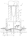
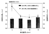
図4は、皮膚突出長yと認識部高さxを測定するための測定装置を示す説明図である。図5は、筒孔直径dを変化させた場合の皮膚突出長yと認識部高さxの測定値を示すグラフである。図6は、認識部長さkを変化させた場合の皮膚突出長yと認識部高さxの測定値を示すグラフである。 FIG. 4 is an explanatory diagram showing a measuring device for measuring the skin protrusion length y and the recognition unit height x. FIG. 5 is a graph showing measured values of the skin protrusion length y and the recognition unit height x when the tube hole diameter d is changed. FIG. 6 is a graph showing measured values of the skin protrusion length y and the recognition unit height x when the recognition unit length k is changed.
まず、この実験に用いた測定装置100について説明する。測定装置100は、合成樹脂(プラスチック)を切削加工することによって形成した。この測定装置100は、円形の筒状に形成された外筒101と、この外筒101の筒孔101aに摺動可能に嵌合された押圧部材102を備えている。
First, the measuring
外筒101の一方の端部(下端部)には、外筒101の半径方向に突出したフランジ103が設けられている。このフランジ103の底面103aは、外筒101の端面と同一の平面を形成している。フランジ103は、注射針組立体1(図1を参照)の距離認識部8に相当する。そして、フランジ103の外面から外筒101の内面までの長さは、注射針組立体1における認識部長さkに相当する。
A
押圧部材102は、外筒101の筒孔101aの直径と略等しい直径の円柱体からなり、上面102aと、底面102bを有している。この押圧部材102の底面102bには、円形の凹部104が設けられている。この凹部104の直径は、注射針組立体1における筒孔直径dに相当する。この凹部104には、測定部材105が摺動可能に嵌合されている。この測定部材105は、凹部104の直径と略等しい直径の円柱体からなり、上面105aと底面105bを有している。
The pressing
一方、押圧部材102の底面102bは、凹部104が設けられることにより、円形のリング状に形成されている。この押圧部材102の底面102bは、注射針組立体1における接触筒部6の端面6bに相当する。なお、今回の実験で用いる測定装置100では、押圧部材102の底面102bの幅が0.5mmに設定されている。
On the other hand, the
このような構成を有する測定装置100を用いて皮膚突出長yと認識部高さxを測定するには、まず、図4(a)に示すように、測定装置100を皮膚に載置する。このとき、外筒101に設けたフランジ103の底面103aと、押圧部材102の底面102bと、測定部材105の底面105bが皮膚に接触している。
In order to measure the skin protrusion length y and the recognition unit height x using the
次に、図4(b)に示すように、押圧部材102の上面102aを押圧する。これにより、押圧部材102が外筒101の筒孔101a内を移動し、底面102bが皮膚に押し付けられる。その結果、外筒101および押圧部材102は、接触筒部6が皮膚に押し付けられた状態の皮膚変形部4と同じ形態になる。
Next, as shown in FIG. 4B, the
押圧部材102の底面102bが皮膚に押し付けられると、凹部104内に皮膚の盛り上がりが形成される。これにより、測定部材105が皮膚の盛り上がりによって押し上げられる。この状態において、押圧部材102の底面102bから測定部材105の底面105bまでの距離は、注射針組立体1の皮膚変形部4によって形成される皮膚の盛り上がりの高さ(皮膚突出長y)に相当する。したがって、押圧部材102の底面102bから測定部材105の底面105bまでの距離を測定することにより、皮膚突出長yを測定することができる。
When the
また、押圧部材102の底面102bからフランジ103の底面103aまでの距離は、注射針組立体1における認識部高さxに相当する。したがって、押圧部材102の底面102bからフランジ103の底面103aまでの距離を測定することにより、認識部高さxを測定することができる。
The distance from the
本実験は、大人10人の三角筋の皮膚における皮膚突出長y及び認識部高さxを測定した。本実験では、まず、凹部104の直径(筒孔直径d)がそれぞれ11mm、12mm、13mm、14mmである4つの測定装置100を用いて皮膚突出長yと認識部高さxを測定した。なお、認識部長さkは、0.5mmにした。そして、押圧部材102を押圧する力は、実用において適用可能な最大値と考えられる20Nを上限とした。この測定により、筒孔直径dの大きさの違いによって皮膚突出長yが変化するか否かを確認することができる。この実験結果を図5に示す。
In this experiment, skin protrusion length y and recognition part height x in the skin of deltoid muscles of 10 adults were measured. In this experiment, first, the skin protrusion length y and the recognition part height x were measured using four
図5に示すように、押圧部材102を20Nで皮膚を押し付けた場合、皮膚突出長yは、1.0〜1.3mmの範囲であった。例えば、筒孔直径dが11mmの場合は、皮膚突出長yが約1.1mmになった。この結果から、筒孔直径dは、11〜14mmの範囲では皮膚突出長yに影響を及ぼし難いことが判った。また、認識部高さxは、筒孔直径dが11mmの場合に約2.6mmシフトし、筒孔直径dが12〜14mmの場合に約1.5mmシフトした。
As shown in FIG. 5, when the skin was pressed against the pressing
次に、認識部高さxが1mmおよび2mmとなるまで押圧したときの皮膚突出長yを測定した。その結果を図6に示す。認識部高さxを1mmとした場合は、筒孔直径dが11〜14mmにおいて、皮膚突出長yが0.5〜0.7mmの範囲であった。皮膚突出長yが一番大きくなったのは、筒孔直径dが12mmのものであり、皮膚突出長yが約0.7mmになった。また、筒孔直径dが11mにおいて、認識部高さxを2mmにすると、皮膚突出長yが約0.8mmになった。 Next, the skin protrusion length y when pressed until the recognition part height x was 1 mm and 2 mm was measured. The result is shown in FIG. When the recognition part height x was 1 mm, the skin protrusion length y was in the range of 0.5 to 0.7 mm when the cylinder hole diameter d was 11 to 14 mm. The skin protrusion length y was the largest when the tube hole diameter d was 12 mm, and the skin protrusion length y was about 0.7 mm. When the cylinder hole diameter d was 11 m and the recognition part height x was 2 mm, the skin protrusion length y was about 0.8 mm.
次に、20Nでの皮膚突出長yは、筒孔直径dを変化させても約1.2mmであるため、筒孔直径dを12mmに設定し、認識部長さkを0.5〜5mmに変化させたときの皮膚突出長yと認識部高さxを測定した。この実験結果を図7に示す。 Next, since the skin protrusion length y at 20N is about 1.2 mm even if the tube hole diameter d is changed, the tube hole diameter d is set to 12 mm and the recognition portion length k is set to 0.5 to 5 mm. The skin protrusion length y and the recognition part height x when changing were measured. The experimental results are shown in FIG.
まず、押圧部材102を押圧する力を20Nにして、皮膚突出長yと認識部高さxを測定した。図7に示すように、認識部長さkが大きくなると、認識部高さxが増大した。また、皮膚突出長yは、約1.0〜1.2mmの範囲であった。
First, the force for pressing the
次に、認識部高さxを1〜8mmに変化させたときの皮膚突出長yを測定した。その結果を図8に示す。認識部高さxが大きくなると、皮膚突出長yが増大した。これにより、皮膚突出長yは、認識部高さxにほぼ比例することが判った(図9参照)。したがって、皮膚突出長yは、認識部高さxに基づいて設定することができる。 Next, the skin protrusion length y when the recognition part height x was changed to 1 to 8 mm was measured. The result is shown in FIG. As the recognition part height x increased, the skin protrusion length y increased. Thereby, it turned out that the skin protrusion length y is substantially proportional to the recognition part height x (refer FIG. 9). Therefore, the skin protrusion length y can be set based on the recognition unit height x.
図9は、認識部高さxと皮膚突出長y(皮膚の盛り上がりの高さ)との関係を示すグラフである。図9に示すように、例えば、認識部長さkが3mmの場合には、皮膚突出長yと認識部高さxが次の関係を満たすことが判った。
y=0.104x+0.097(相関係数0.99)
また、認識部長さkが5mmの場合には、皮膚突出長yと認識部高さxが次の関係を満たすことが判った。
y=0.090x+0.090(相関係数0.98)
FIG. 9 is a graph showing the relationship between the recognition unit height x and the skin protrusion length y (height of skin swell). As shown in FIG. 9, for example, when the recognition part length k is 3 mm, it has been found that the skin protrusion length y and the recognition part height x satisfy the following relationship.
y = 0.104x + 0.097 (correlation coefficient 0.99)
Moreover, when the recognition part length k was 5 mm, it turned out that the skin protrusion length y and the recognition part height x satisfy | fill the following relationship.
y = 0.090x + 0.090 (correlation coefficient 0.98)
なお、上述した2つの関係式は、定数が略同じであるといえる。つまり、各定数の小数点第二位を四捨五入すると、皮膚突出長yと認識部高さxが次の関係を満たすといえる。
y=0.1x+0.1
したがって、認識部長さkが3.0〜5.0mmの範囲でこの関係式を適用することが可能である。
It can be said that the two relational expressions described above have substantially the same constants. That is, when the second decimal place of each constant is rounded off, it can be said that the skin protrusion length y and the recognition part height x satisfy the following relationship.
y = 0.1x + 0.1
Therefore, it is possible to apply this relational expression when the recognition section length k is in the range of 3.0 to 5.0 mm.
また、認識部長さkが0.5mmの場合は、認識部高さxを1mmにすることは可能であったが、認識部高さxを2mm以上に変化させることができなかった。つまり、認識部高さxが2mmになるまで押圧部材102を皮膚に押し付けようとしても、フランジ103の底面103aが皮膚と接触しなかった。したがって、認識部長さkを0.5mmに設定する場合は、認識部高さxを1mm以内にするとよいことが判った。同様に、認識部長さkを1.0mmに設定する場合は、認識部高さxを2mm以内にするとよいことが判った。
When the recognition unit length k is 0.5 mm, the recognition unit height x can be set to 1 mm, but the recognition unit height x cannot be changed to 2 mm or more. That is, even if the
以上の実験結果から、認識部高さxを変化させることにより、穿刺長P(図3を参照)を規定できることが判った。例えば、認識部長さkを0.5mmに設定し、認識部高さxを約1.5mmに設定すれば、皮膚突出長yが約1.2mmになる。したがって、針突出長Lを0.2mmに設定すれば、穿刺長Pを1.4(1.2+0.2=1.4)mmにすることができ、針管2の先端を大人の皮膚上層部に確実に位置させることができる。また、針突出長Lを−0.3mmに設定すれば、穿刺長Pを0.9(1.2−0.3=0.9)mmにすることができ、小児の皮膚上層部に針先を確実に位置させることができる。
From the above experimental results, it was found that the puncture length P (see FIG. 3) can be defined by changing the recognition unit height x. For example, if the recognition part length k is set to 0.5 mm and the recognition part height x is set to about 1.5 mm, the skin protrusion length y is about 1.2 mm. Therefore, if the needle protrusion length L is set to 0.2 mm, the puncture length P can be set to 1.4 (1.2 + 0.2 = 1.4) mm, and the tip of the
また、認識部長さkの範囲が3.0〜5.0mmであって、筒孔直径dの範囲が11〜14mmである場合において、認識部高さxと皮膚突出長yがy=0.1x+0.1という関係式を満たすことが判った。そのため、この関係式にしたがって皮膚突出長yを規定することができる。そして、規定した皮膚突出長yと穿刺長Pから針突出長Lを決定することができる(L=P−y)。 In the case where the range of the recognition part length k is 3.0 to 5.0 mm and the range of the cylinder hole diameter d is 11 to 14 mm, the recognition part height x and the skin protrusion length y are y = 0. It was found that the relational expression of 1x + 0.1 was satisfied. Therefore, the skin protrusion length y can be defined according to this relational expression. The needle protrusion length L can be determined from the defined skin protrusion length y and puncture length P (L = P−y).
2.第2の実施の形態
[注射針組立体および薬剤注射装置の構成例]
次に、本発明の注射針組立体および薬剤注射装置の第2の実施の形態について、図10を参照して説明する。
図10は、本発明の注射針組立体の第2の実施の形態を示す構成図である。
2. Second Embodiment [Configuration Example of Needle Assembly and Drug Injection Device]
Next, a second embodiment of the needle assembly and drug injection device of the present invention will be described with reference to FIG.
FIG. 10 is a block diagram showing a second embodiment of the injection needle assembly of the present invention.
注射針組立体11は、第1の実施の形態の注射針組立体1と同様な構成を有しており、異なるところは、皮膚変形部14および距離認識部18である。そのため、ここでは、皮膚変形部14および距離認識部18について説明し、注射針組立体1と共通する部分には同一の符号を付して重複した説明を省略する。
The
なお、本発明の薬剤注射装置は、注射針組立体11のハブ3にシリンジ9(図3を参照)を接続することによって構成される。
The drug injection device of the present invention is configured by connecting a syringe 9 (see FIG. 3) to the
皮膚変形部14は、筒状に形成されており、一方の端部を形成する固定筒部15と、この固定筒部15に連続し、他方の端部を形成する接触筒部16を有している。この皮膚変形部14の材質としては、ポリカーボネート、ポリプロピレン、ポリエチレン等の合成樹脂(プラスチック)を用いてもよく、また、ステンレス、アルミニウム等の金属を用いてもよい。
The
皮膚変形部14の固定筒部15は、第1の実施の形態の固定筒部5と同じ形状であり、筒孔15aを有する円筒体からなっている。この固定筒部15の一方の端部は、ハブ3のフランジ3bに接着剤などの固定方法によって固定されている。また、固定筒部5の他方の端部は、接触筒部16に連続している。そして、固定筒部5の筒孔15aには、ハブ3のハブ本体3aが収納されている。
The fixed
皮膚変形部14の接触筒部16は、固定筒部15よりも直径の大きい円筒体からなり、固定筒部15の筒孔15aに連通する筒孔16aを有している。この筒孔16aの直径は、固定筒部15の筒孔15aの直径よりも大きくなっている。接触筒部16の筒孔16aには、ハブ3に保持された針管2が配置される。また、筒孔16aの中心線は、針管2の軸心と一致している。
The contact
接触筒部16の端面16bは、皮膚上層部に針管2を穿刺する場合に皮膚の表面に接触して押し付けられる。この端面16bが皮膚に押し付けられると、接触筒部16の筒孔6a内には、皮膚の盛り上がりが形成される。そして、針管2は、筒孔16a内に形成された皮膚の盛り上がりに穿刺される。
The
接触筒部6の端部には、距離認識部18が設けられている。この距離認識部18は、接触筒部16の端面16bを切り欠いて段部を設けることで形成されており、当接面18aと、壁面18bを有している。
A
距離認識部18の当接面18aは、接触筒部16の端面16bと平行な平面であり、接触筒部16の周方向に連続する円形のリング状に形成されている。この当接面18aから接触筒部16の端面16bまでの距離は、第1の実施の形態の「認識部高さx」に相当する。また、壁面18bは、接触筒部16の周方向に連続する曲面になっている。この壁面18bから接触筒部16の外面までの距離は、第1の実施の形態の「認識部長さk」に相当する。言い換えれば、当接面18aにおいて、接触筒部16の外面に直交する方向の長さが「認識部長さk」に相当する。
The
このような構成を有する注射針組立体11によっても、上述した第1の実施の形態の注射針組立体1と同様の作用及び効果を得ることができる。つまり、距離認識部18の当接面18aが皮膚に接触するまで接触筒部16を押し付けることにより、接触筒部6が皮膚を押し込む距離を常に一定にすることができる。
Also with the
その結果、接触筒部16の筒孔16a内に形成される皮膚の盛り上がりの高さを略一定にすることができる。針管2が皮膚内に穿刺される深さは、皮膚の盛り上がりの高さに、接触筒部16の端面16bから針管2の針先までの距離を足した値と等しくなる。したがって、皮膚の盛り上がりの高さを略一定にすることにより、針管2が皮膚内に穿刺される深さを略一定にすることができる。
As a result, the height of the skin swell formed in the
3.第3の実施の形態
[注射針組立体および薬剤注射装置の構成例]
次に、本発明の注射針組立体および薬剤注射装置の第3の実施の形態について、図11を参照して説明する。
図11は、本発明の注射針組立体の第3の実施の形態を示す斜視図である。
3. Third Embodiment [Configuration Example of Injection Needle Assembly and Drug Injection Device]
Next, a third embodiment of the injection needle assembly and drug injection device of the present invention will be described with reference to FIG.
FIG. 11 is a perspective view showing a third embodiment of the injection needle assembly of the present invention.
注射針組立体21は、第1の実施の形態の注射針組立体1と同様な構成を有しており、異なるところは、距離認識部28である。そのため、ここでは、距離認識部28について説明し、注射針組立体1と共通する部分には同一の符号を付して重複した説明を省略する。
The
なお、注射針組立体21は、第1の実施の形態と同様のハブ3(図1を参照)を備えている。そして、本発明の薬剤注射装置は、注射針組立体21のハブ3にシリンジ9(図3を参照)を接続することによって構成される。
The
注射針組立体21の距離認識部28は、接触筒部6に設けられた目盛りである。この距離認識部28は、接触筒部6に印刷或いは塗装を施すことによって形成されている。なお、印刷或いは塗装を施す部位は、接触筒部6の外面であってもよく、また、内面であってもよい。距離認識部28は、接触筒部6の周方向に連続して形成されており、どの方向から見ても認識できるようになっている。この距離認識部28から接触筒部6の端面6bまでの距離は、第1の実施の形態の「認識部高さx」に相当する。
The
このような構成を有する注射針組立体21によっても、上述した第1の実施の形態の注射針組立体1と同様の作用及び効果を得ることができる。つまり、距離認識部18(目盛り)が接触筒部6の周囲の皮膚の表面に一致するまで接触筒部6を皮膚に押し付けることにより、接触筒部6が皮膚を押し込む距離を常に一定にすることができる。
Also with the
その結果、接触筒部6の筒孔6a内に形成される皮膚の盛り上がりの高さを略一定にすることができる。針管2が皮膚内に穿刺される深さは、筒孔6a内に形成される皮膚の盛り上がりの高さに、接触筒部6の端面6bから針管2の針先までの距離を足した値と等しくなる。したがって、皮膚の盛り上がりの高さを略一定にすることにより、針管2が皮膚内に穿刺される深さを略一定にすることができる。
As a result, the height of the skin swell formed in the
本実施の形態では、接触筒部6に印刷或いは塗装を施すことによって距離認識部28形成したが、その他の方法によって距離認識部28を形成してもよい。距離認識部28としては、例えば、接触筒部6に溝を設けることによって形成してもよく、シートを貼り付けることにより形成してもよい。
In the present embodiment, the
また、本実施の形態では、距離認識部(目盛り)28を1つ設けたが、本発明に係る注射針組立体としては、距離認識部(目盛り)を2つ以上設けることもできる。例えば、小児用の距離認識部(目盛り)と大人用の距離認識部(目盛り)を設けてもよい。その場合、小児用の距離認識部の認識部高さxよりも大人用の距離認識部の認識部高さxを高く(大きく)して、小児の皮膚上層部に針管2が穿刺される深さよりも大人の皮膚上層部に針管2が穿刺される深さをより深くする。これにより、皮膚上層部の厚みに応じて針管2が穿刺される深さを変化させることができ、針管2の針先を皮膚上層部内に確実に位置させることができる。
In the present embodiment, one distance recognition unit (scale) 28 is provided. However, as the injection needle assembly according to the present invention, two or more distance recognition units (scale) can be provided. For example, a distance recognition unit (scale) for children and a distance recognition unit (scale) for adults may be provided. In this case, the recognition unit height x of the adult distance recognition unit is set higher (larger) than the recognition unit height x of the child distance recognition unit, and the depth at which the
本発明の注射針組立体および薬剤注射装置は、上述の実施形態に限定されるものではなく、その他材料、構成等において本発明の構成を逸脱しない範囲において種々の変形、変更が可能であることはいうまでもない。 The injection needle assembly and the drug injection device of the present invention are not limited to the above-described embodiment, and various modifications and changes can be made without departing from the configuration of the present invention in terms of other materials and configurations. Needless to say.
第1〜第3の実施の形態では、ハブ3に皮膚変形部4(14)を固定したが、本発明に係る皮膚変形部としては、例えば、薬剤注射装置を構成するシリンジに固定してもよい。また、本発明に係る皮膚変形部としては、ハブ或いはシリンジと一体成形することもできる。
In the first to third embodiments, the skin deforming portion 4 (14) is fixed to the
1,11,21…注射針組立体
2…針管
2a…針孔
2b…刃面
3…ハブ
4,14…皮膚変形部
5,15…固定筒部
6,16…接触筒部
6a,16a…筒孔
6b,16b…端面
8,18,28…距離認識部
9…シリンジ
B…ベベル長
L…針突出長
P…穿刺長
d…筒孔直径
k…認識部長さ
x…認識部高さ
y…皮膚突出長
DESCRIPTION OF
Claims (8)
前記針管を保持するハブと、
前記針管の周囲を囲うように筒状に形成され、端面が皮膚に押し付けられることにより、筒孔内で前記針管に穿刺される皮膚の盛り上がりを形成する皮膚変形部と、
前記皮膚変形部の外周面に設けられた段部であり、前記皮膚変形部の前記端面に平行な当接面を有し、前記当接面が皮膚に接触することにより皮膚に対して前記皮膚変形部が押し込まれる距離を認識させる距離認識部と、を備え、
前記皮膚変形部は、前記距離認識部の前記当接面に皮膚が接触するまで皮膚に押し付けられる
ことを特徴とする注射針組立体。 A needle tube having a needle tip that can puncture a living body;
A hub for holding the needle tube;
A skin deforming part that is formed in a cylindrical shape so as to surround the periphery of the needle tube, and an end surface is pressed against the skin, thereby forming a skin swell that is punctured into the needle tube in a cylindrical hole;
A step provided on an outer peripheral surface of the skin deforming portion, having a contact surface parallel to the end surface of the skin deforming portion, and the skin contacting the skin by the contact surface contacting the skin; A distance recognizing unit for recognizing a distance into which the deforming unit is pushed ,
The injection needle assembly , wherein the skin deforming portion is pressed against the skin until the skin contacts the contact surface of the distance recognition portion .
y=0.1x+0.1
の関係を満たすことを特徴とする請求項6記載の注射針組立体。 When the recognition part length is set to 3.0 to 5.0 mm, y is the height of the skin swell, and x is the distance from the end face of the skin deformation part to the distance recognition part. And x are
y = 0.1x + 0.1
The injection needle assembly according to claim 6 , wherein the relationship is satisfied.
前記針管を保持するハブと、
前記針管の周囲を囲うように筒状に形成され、端面が皮膚に押し付けられることにより、筒孔内で前記針管に穿刺される皮膚の盛り上がりを形成する皮膚変形部と、
前記皮膚変形部の外周面に設けられた段部であり、前記皮膚変形部の前記端面に平行な当接面を有し、前記当接面が皮膚に接触することにより皮膚に対して前記皮膚変形部が押し込まれる距離を認識させる距離認識部と、
前記ハブに接続されるシリンジと、を備え、
前記皮膚変形部は、前記距離認識部の前記当接面に皮膚が接触するまで皮膚に押し付けられる
ことを特徴とする薬剤注射装置。 A needle tube having a needle tip that can puncture a living body;
A hub for holding the needle tube;
A skin deforming part that is formed in a cylindrical shape so as to surround the periphery of the needle tube, and an end surface is pressed against the skin, thereby forming a skin swell that is punctured into the needle tube in a cylindrical hole;
A step provided on an outer peripheral surface of the skin deforming portion, having a contact surface parallel to the end surface of the skin deforming portion, and the skin contacting the skin by the contact surface contacting the skin; A distance recognition unit for recognizing the distance to which the deformation unit is pushed;
A syringe connected to the hub ,
The drug injection device , wherein the skin deforming portion is pressed against the skin until the skin contacts the contact surface of the distance recognition portion .
Priority Applications (9)
| Application Number | Priority Date | Filing Date | Title |
|---|---|---|---|
| JP2009021771A JP5366196B2 (en) | 2009-02-02 | 2009-02-02 | Injection needle assembly and drug injection device |
| TW099102421A TWI449551B (en) | 2009-01-30 | 2010-01-28 | Injection needle assembly and drug injection device |
| CN201080004159.0A CN102271738B (en) | 2009-01-30 | 2010-01-29 | Injection needle assembly and drug injection device |
| MYPI2011003543A MY155501A (en) | 2009-01-30 | 2010-01-29 | Injection needle assembly and drug injection device |
| EP10709292.6A EP2398536B1 (en) | 2009-01-30 | 2010-01-29 | Injection needle assembly and drug injection device |
| US13/145,427 US8622963B2 (en) | 2009-01-30 | 2010-01-29 | Injection needle assembly and drug injection device |
| PCT/JP2010/051662 WO2010087524A2 (en) | 2009-01-30 | 2010-01-29 | Injection needle assembly and drug injection device |
| ES10709292.6T ES2534835T3 (en) | 2009-01-30 | 2010-01-29 | Hypodermic needle set and drug injection device |
| US14/108,699 US9566393B2 (en) | 2009-01-30 | 2013-12-17 | Injection needle assembly and drug injection device |
Applications Claiming Priority (1)
| Application Number | Priority Date | Filing Date | Title |
|---|---|---|---|
| JP2009021771A JP5366196B2 (en) | 2009-02-02 | 2009-02-02 | Injection needle assembly and drug injection device |
Publications (2)
| Publication Number | Publication Date |
|---|---|
| JP2010172662A JP2010172662A (en) | 2010-08-12 |
| JP5366196B2 true JP5366196B2 (en) | 2013-12-11 |
Family
ID=42704156
Family Applications (1)
| Application Number | Title | Priority Date | Filing Date |
|---|---|---|---|
| JP2009021771A Active JP5366196B2 (en) | 2009-01-30 | 2009-02-02 | Injection needle assembly and drug injection device |
Country Status (1)
| Country | Link |
|---|---|
| JP (1) | JP5366196B2 (en) |
Cited By (2)
| Publication number | Priority date | Publication date | Assignee | Title |
|---|---|---|---|---|
| KR20180082751A (en) * | 2017-01-11 | 2018-07-19 | 주식회사 제이티에스인더스트리 | Face Fit Eyebrow tattoo system using 3D Face Recognition Scanner |
| WO2019176523A1 (en) | 2018-03-12 | 2019-09-19 | テルモ株式会社 | Intradermal needle and package therefor, and injection device |
Families Citing this family (1)
| Publication number | Priority date | Publication date | Assignee | Title |
|---|---|---|---|---|
| EP2802371A1 (en) * | 2012-01-10 | 2014-11-19 | Sanofi-Aventis Deutschland GmbH | Guiding assembly for intradermal injection |
Family Cites Families (2)
| Publication number | Priority date | Publication date | Assignee | Title |
|---|---|---|---|---|
| WO2004069301A2 (en) * | 2003-01-30 | 2004-08-19 | Becton, Dickinson And Company | Intradermal delivery device with contoured skin engaging surface geometry |
| US7842008B2 (en) * | 2005-11-21 | 2010-11-30 | Becton, Dickinson And Company | Intradermal delivery device |
-
2009
- 2009-02-02 JP JP2009021771A patent/JP5366196B2/en active Active
Cited By (3)
| Publication number | Priority date | Publication date | Assignee | Title |
|---|---|---|---|---|
| KR20180082751A (en) * | 2017-01-11 | 2018-07-19 | 주식회사 제이티에스인더스트리 | Face Fit Eyebrow tattoo system using 3D Face Recognition Scanner |
| WO2019176523A1 (en) | 2018-03-12 | 2019-09-19 | テルモ株式会社 | Intradermal needle and package therefor, and injection device |
| US11813440B2 (en) | 2018-03-12 | 2023-11-14 | Terumo Kabushiki Kaisha | Intradermal needle, packaged article, and injection device |
Also Published As
| Publication number | Publication date |
|---|---|
| JP2010172662A (en) | 2010-08-12 |
Similar Documents
| Publication | Publication Date | Title |
|---|---|---|
| JP5618989B2 (en) | Injection needle assembly and drug injection device | |
| US9566393B2 (en) | Injection needle assembly and drug injection device | |
| JP5430646B2 (en) | Injection needle and drug injection device | |
| WO2011122224A1 (en) | Injection needle assembly and drug injection device | |
| JP5667571B2 (en) | Injection needle assembly and drug injection device | |
| JP5726741B2 (en) | Injection needle assembly and drug injection device | |
| JP5719522B2 (en) | Drug administration device and drug injection device | |
| JP5604438B2 (en) | Injection needle assembly and drug injection device | |
| EP3248634B1 (en) | Injection needle assembly and injector provided therewith for injecting drug solution into upper layer of skin | |
| JP5955838B2 (en) | Injection needle assembly and drug injection device | |
| JP5366195B2 (en) | Injection needle assembly and drug injection device | |
| JP5366196B2 (en) | Injection needle assembly and drug injection device | |
| JP5432272B2 (en) | Injection aid and drug injection device | |
| WO2011040222A1 (en) | Hypodermic needle assembly and medicine injection device | |
| JP2011010999A (en) | Injection needle assembly and medicine injection device | |
| JP5270424B2 (en) | Drug injection device and needle assembly | |
| JP5520109B2 (en) | Injection needle assembly and drug injection device | |
| JP5520110B2 (en) | Injection needle assembly and drug injection device |
Legal Events
| Date | Code | Title | Description |
|---|---|---|---|
| A621 | Written request for application examination |
Free format text: JAPANESE INTERMEDIATE CODE: A621 Effective date: 20120111 |
|
| A131 | Notification of reasons for refusal |
Free format text: JAPANESE INTERMEDIATE CODE: A131 Effective date: 20130129 |
|
| A521 | Request for written amendment filed |
Free format text: JAPANESE INTERMEDIATE CODE: A523 Effective date: 20130321 |
|
| TRDD | Decision of grant or rejection written | ||
| A01 | Written decision to grant a patent or to grant a registration (utility model) |
Free format text: JAPANESE INTERMEDIATE CODE: A01 Effective date: 20130813 |
|
| A61 | First payment of annual fees (during grant procedure) |
Free format text: JAPANESE INTERMEDIATE CODE: A61 Effective date: 20130905 |
|
| R150 | Certificate of patent or registration of utility model |
Ref document number: 5366196 Country of ref document: JP Free format text: JAPANESE INTERMEDIATE CODE: R150 Free format text: JAPANESE INTERMEDIATE CODE: R150 |
|
| R250 | Receipt of annual fees |
Free format text: JAPANESE INTERMEDIATE CODE: R250 |
|
| R250 | Receipt of annual fees |
Free format text: JAPANESE INTERMEDIATE CODE: R250 |
|
| R250 | Receipt of annual fees |
Free format text: JAPANESE INTERMEDIATE CODE: R250 |
|
| R250 | Receipt of annual fees |
Free format text: JAPANESE INTERMEDIATE CODE: R250 |
|
| R250 | Receipt of annual fees |
Free format text: JAPANESE INTERMEDIATE CODE: R250 |
|
| R250 | Receipt of annual fees |
Free format text: JAPANESE INTERMEDIATE CODE: R250 |