JP5364118B2 - Drawer type circuit breaker and switchboard - Google Patents
Drawer type circuit breaker and switchboard Download PDFInfo
- Publication number
- JP5364118B2 JP5364118B2 JP2011050897A JP2011050897A JP5364118B2 JP 5364118 B2 JP5364118 B2 JP 5364118B2 JP 2011050897 A JP2011050897 A JP 2011050897A JP 2011050897 A JP2011050897 A JP 2011050897A JP 5364118 B2 JP5364118 B2 JP 5364118B2
- Authority
- JP
- Japan
- Prior art keywords
- circuit breaker
- type circuit
- drawer
- interlock
- switchboard
- Prior art date
- Legal status (The legal status is an assumption and is not a legal conclusion. Google has not performed a legal analysis and makes no representation as to the accuracy of the status listed.)
- Active
Links
Images


Classifications
-
- H—ELECTRICITY
- H01—ELECTRIC ELEMENTS
- H01H—ELECTRIC SWITCHES; RELAYS; SELECTORS; EMERGENCY PROTECTIVE DEVICES
- H01H33/00—High-tension or heavy-current switches with arc-extinguishing or arc-preventing means
- H01H33/02—Details
- H01H33/46—Interlocking mechanisms
- H01H33/48—Interlocking mechanisms for interlocking between casing or cover and mechanism for operating contacts
-
- H—ELECTRICITY
- H02—GENERATION; CONVERSION OR DISTRIBUTION OF ELECTRIC POWER
- H02B—BOARDS, SUBSTATIONS OR SWITCHING ARRANGEMENTS FOR THE SUPPLY OR DISTRIBUTION OF ELECTRIC POWER
- H02B11/00—Switchgear having carriage withdrawable for isolation
- H02B11/12—Switchgear having carriage withdrawable for isolation with isolation by horizontal withdrawal
- H02B11/127—Withdrawal mechanism
- H02B11/133—Withdrawal mechanism with interlock
-
- H—ELECTRICITY
- H01—ELECTRIC ELEMENTS
- H01H—ELECTRIC SWITCHES; RELAYS; SELECTORS; EMERGENCY PROTECTIVE DEVICES
- H01H33/00—High-tension or heavy-current switches with arc-extinguishing or arc-preventing means
- H01H33/60—Switches wherein the means for extinguishing or preventing the arc do not include separate means for obtaining or increasing flow of arc-extinguishing fluid
- H01H33/66—Vacuum switches
-
- H—ELECTRICITY
- H01—ELECTRIC ELEMENTS
- H01H—ELECTRIC SWITCHES; RELAYS; SELECTORS; EMERGENCY PROTECTIVE DEVICES
- H01H71/00—Details of the protective switches or relays covered by groups H01H73/00 - H01H83/00
- H01H71/10—Operating or release mechanisms
- H01H71/50—Manual reset mechanisms which may be also used for manual release
- H01H71/505—Latching devices between operating and release mechanism
-
- H—ELECTRICITY
- H01—ELECTRIC ELEMENTS
- H01H—ELECTRIC SWITCHES; RELAYS; SELECTORS; EMERGENCY PROTECTIVE DEVICES
- H01H71/00—Details of the protective switches or relays covered by groups H01H73/00 - H01H83/00
- H01H71/10—Operating or release mechanisms
- H01H71/50—Manual reset mechanisms which may be also used for manual release
- H01H71/52—Manual reset mechanisms which may be also used for manual release actuated by lever
-
- H—ELECTRICITY
- H01—ELECTRIC ELEMENTS
- H01H—ELECTRIC SWITCHES; RELAYS; SELECTORS; EMERGENCY PROTECTIVE DEVICES
- H01H9/00—Details of switching devices, not covered by groups H01H1/00 - H01H7/00
- H01H9/10—Adaptation for built-in fuses
-
- H—ELECTRICITY
- H01—ELECTRIC ELEMENTS
- H01H—ELECTRIC SWITCHES; RELAYS; SELECTORS; EMERGENCY PROTECTIVE DEVICES
- H01H9/00—Details of switching devices, not covered by groups H01H1/00 - H01H7/00
- H01H9/20—Interlocking, locking, or latching mechanisms
- H01H9/26—Interlocking, locking, or latching mechanisms for interlocking two or more switches
-
- H—ELECTRICITY
- H02—GENERATION; CONVERSION OR DISTRIBUTION OF ELECTRIC POWER
- H02B—BOARDS, SUBSTATIONS OR SWITCHING ARRANGEMENTS FOR THE SUPPLY OR DISTRIBUTION OF ELECTRIC POWER
- H02B11/00—Switchgear having carriage withdrawable for isolation
- H02B11/26—Arrangements of fuses, resistors, voltage arresters or the like
Landscapes
- Engineering & Computer Science (AREA)
- Power Engineering (AREA)
- Physics & Mathematics (AREA)
- Electromagnetism (AREA)
- Trip Switchboards (AREA)
- Distribution Board (AREA)
- Patch Boards (AREA)
- Driving Mechanisms And Operating Circuits Of Arc-Extinguishing High-Tension Switches (AREA)
- Breakers (AREA)
Description
本発明は引出形回路遮断器及び配電盤に係り、特に、電気回路の電流を投入、遮断するための引出形回路遮断器の配電盤内における適切な位置での固定及び引出形回路遮断器の入状態におけるせりだし、誤引出しを防止するために設けられているインターロック装置を備えているものに好適な引出形回路遮断器及び配電盤に関する。 The present invention relates to a pull Degata circuit breakers and switchboard, particularly charged current of the electrical circuit, the fixed and pull-out type circuit breaker in place in the switchboard in the draw-out type circuit breaker for interrupting entry it's auction in the state, of a preferred drawer-type circuit breaker and the switchboard to what is provided with a though Louis interlock device provided in order to prevent false drawer.
一般に、引出形回路遮断器は、電気回路において電源と負荷との間に接続され、主回路電流の入切に使用される遮断器の一種であり、配電盤内に収納、固定された状態で使用される。 In general, a draw-out type circuit breaker is a type of circuit breaker that is connected between a power source and a load in an electric circuit and used to turn on and off the main circuit current, and is used while being housed and fixed in a switchboard. Is done.
この引出形回路遮断器は、主回路の入切をするための主接点、主接点を駆動するための駆動装置、主回路電流を通電するための主回路通電部、引出形回路遮断器の主回路通電部と配電盤内の主回路とを着脱自在にするための接続部、引出形回路遮断器を移動するための移動装置および配電盤内に収納された引出形回路遮断器を適切な位置で固定するためのインターロック装置などから概略構成される。 This drawer type circuit breaker is composed of a main contact for turning on and off the main circuit, a driving device for driving the main contact, a main circuit energizing part for energizing the main circuit current, and a main circuit of the drawer type circuit breaker. Fix the connection part to make the circuit energization part and the main circuit in the switchboard detachable, the moving device to move the drawer-type circuit breaker, and the drawer-type circuit breaker housed in the switchboard at an appropriate position. It is roughly composed of an interlock device or the like.
運用においては、通常、配電盤内の主回路と引出形遮断器の接続部が適切に接続される運転位置で、インターロック装置により引出形回路遮断器は固定される。 In operation, the drawer-type circuit breaker is usually fixed by an interlock device at an operating position where the main circuit in the switchboard is properly connected to the connection part of the drawer-type breaker.
これにより、配電盤内の主回路と引出形回路遮断器の接続部、通電部及び主接点が主回路を構成し、引出形回路遮断器の主接点を入切することで電源から負荷への電力の供給および遮断を実施している。 As a result, the main circuit in the switchboard and the connection part of the lead-out type circuit breaker, the energization part and the main contact constitute the main circuit, and the main contact of the lead-out type circuit breaker is turned on and off to power from the power source to the load. Supplying and shutting down
また、従来のインターロック装置としては、特許文献1に記載されているものがあり、この特許文献1に記載されているインターロック装置は、インターロックロッド、インターロックスイッチ、制御基板等を有しており、インターロックロッドの動作により、インターロックスイッチが制御基板に入力される投入指令を強制的に遮断することを特徴としている。
In addition, as a conventional interlock device, there is one described in
ところで、引出形回路遮断器が入状態のときに引出形回路遮断器を運転位置から移動させたり、運転位置に移動させたりすると、配電盤内の主回路と引出形回路遮断器の接続部間にアークが発生し、機器に深刻な損傷を与えたり、最悪の場合には変電所の火災等に至る可能性がある。 By the way, if the drawer-type circuit breaker is moved from the operating position or moved to the operating position when the drawer-type circuit breaker is in the ON state, the connection between the main circuit in the switchboard and the drawer-type circuit breaker An arc may occur, seriously damaging the equipment, and in the worst case, a substation fire may occur.
そのため、配電盤内の主回路と引出形回路遮断器の接続が適切に接続された運転位置、配電盤内の主回路と引出形回路遮断器の接続部が必要な絶縁距離を確保した断路位置で確実に固定されること、引出形回路遮断器を運転位置から移動させるとき及び運転位置に移動させるときは必ず切状態であること、引出形回路遮断器が運転位置、断路位置以外に配置しているときは常に切状態が継続することの3点が非常に重要であり、インターロック装置により、それらの機能を満足させる必要がある。 Therefore, the operation position where the connection between the main circuit in the switchboard and the draw-out type circuit breaker is properly connected, and the connection position between the main circuit and the draw-out type circuit breaker in the switchboard are ensured at the disconnect position where the necessary insulation distance is secured. It is always in the off state when the drawer type circuit breaker is moved from the operating position and when it is moved to the operating position, and the drawer type circuit breaker is arranged at other than the operating position and disconnecting position. Sometimes the three points that the off state always continues are very important, and it is necessary to satisfy these functions by the interlock device.
インターロック装置が、これらの機能を満足していない場合、入状態の引出形回路遮断器の振動によるせり出し、誤引出しおよび誤挿入により、前述の機器損傷や変電所の火災に至る可能性がある。 If the interlock device does not satisfy these functions, the above-mentioned equipment damage or substation fire may be caused by the pull-out, erroneous pull-out and mis-insertion due to the vibration of the drawer circuit breaker in the on state. .
しかしながら、特許文献1に記載されているインターロック装置には、上記の点については全く記載されていない。
However, the interlock device described in
本発明は上述の点に鑑みなされたもので、その目的とするところは、電気回路の電流を投入、遮断するための引出形回路遮断器の配電盤内における適切な位置での固定は勿論、入状態の引出形回路遮断器の振動によるせり出し、誤引出しおよび誤挿入に起因するアークによる機器の損傷、変電所火災等の重大事故のポテンシャルを排除することができる引出形回路遮断器及び配電盤を提供することにある。 The present invention has been made in view of the above-mentioned points, and the object of the present invention is to fix the drawer type circuit breaker for turning on and off the electric circuit current at an appropriate position in the switchboard. protruding due to vibration of the state of the draw out circuit breaker, false drawer and erroneous equipment damage due to arc to the insertion, the draw-out type circuit breaker can be eliminated the potential of serious accidents substation fire及beauty electrical distribution To provide a board.
本発明の引出形回路遮断器は、上記目的を達成するために、主回路の入切をするための主接点と、該主接点を駆動するための駆動装置と、主回路電流を通電するための主回路通電部と、該主回路通電部と配電盤内の主回路とを着脱自在にするための接続部と、引出形回路遮断器を移動するための移動装置と、配電盤内に収納された引出形回路遮断器を所定の位置で固定するためのインターロック装置とを備えた引出形回路遮断器において、
前記インターロック装置は、引出形回路遮断器の引外し機構部と連結した引外しボタンと、昇降自在に配置されたインターロックロッドとを備え、前記インターロックロッドは、該インターロックロッドと一体に構成され、該インターロックロッドを前記引出形回路遮断器の固定位置及び移動可能位置に移動させるインターロックピンを備え、かつ、前記インターロックピンは、前記移動装置に固定されているインターロックピン金具の正面に形成されているコの字形の穴を移動することで、引出形回路遮断器の移動可能位置及び固定位置に移動するものであり、前記引外しボタンを操作して引出形回路遮断器を切状態にしない限り、前記引外しボタンにより機械的に前記インターロックロッドの上昇操作が阻止されることで、配電盤床面若しくは配電盤床面に固定された部材と前記インターロックロッドが機械的に干渉し、配電盤内の所定の位置で前記引出形回路遮断器を固定すると共に、前記インターロックピン金具の正面に形成されているコの字形の穴の上部に前記インターロックロッドが位置しているとき、前記引外しボタンと前記インターロックロッドが機械的に干渉することで前記引外しボタンが常に操作された状態となり、切状態を継続することを特徴とする。
In order to achieve the above object, a drawer type circuit breaker according to the present invention supplies a main contact for turning on and off a main circuit, a drive device for driving the main contact, and a main circuit current. A main circuit energization section, a connection section for making the main circuit energization section and the main circuit in the switchboard detachable, a moving device for moving the drawer type circuit breaker, and a switchboard housed in the switchboard In a drawer type circuit breaker provided with an interlock device for fixing the drawer type circuit breaker at a predetermined position,
The interlock device includes a trip button connected to a trip mechanism of a drawer type circuit breaker, and an interlock rod arranged to be movable up and down, and the interlock rod is integrated with the interlock rod. An interlock pin fitting comprising an interlock pin configured to move the interlock rod to a fixed position and a movable position of the drawer type circuit breaker, and the interlock pin being fixed to the moving device Is moved to a movable position and a fixed position of the drawer-type circuit breaker by moving a U-shaped hole formed in the front of the drawer, and the drawer-type circuit breaker is operated by operating the trip button Unless the switch is turned off, the operation of raising the interlock rod is mechanically prevented by the trip button. In addition, a member fixed to the switchboard floor and the interlock rod mechanically interfere to fix the drawer-type circuit breaker at a predetermined position in the switchboard and are formed on the front surface of the interlock pin fitting. When the interlock rod is located above the U-shaped hole, the trip button and the interlock rod are mechanically interfered with each other so that the trip button is always operated. It is characterized by continuing the off state .
また、本発明の配電盤は、上記目的を達成すために、盤内に設置されている主回路ケーブル主回路導体、主回路母線、主回路端子接続部を備え、前記主回路端子接続部と電気的に着脱自在で、かつ、運転位置及び断路位置に移動可能な引出形回路遮断器を収納している配電盤において、前記引出形回路遮断器は、上記構成の引出形回路遮断器であることを特徴とする。 In order to achieve the above object, the switchboard according to the present invention includes a main circuit cable main circuit conductor, a main circuit bus, and a main circuit terminal connection portion installed in the panel, and the main circuit terminal connection portion and the electric circuit board are electrically connected. In a switchboard that houses a drawer type circuit breaker that is detachable and can be moved to an operating position and a disconnection position, the drawer type circuit breaker is a drawer type circuit breaker having the above-described configuration. Features.
本発明によれば、引出形回路遮断器は運転位置、断路位置で確実に固定され、引出形回路遮断器を運転位置から移動させるときおよび運転位置へ移動させるときは必ず切状態となる。また、引出形回路遮断器が運転位置、断路位置以外に配置しているときは常に切状態を継続する。 According to the present invention, the drawer-type circuit breaker is securely fixed at the operation position and the disconnection position, and is always in the off state when the drawer-type circuit breaker is moved from the operation position to the operation position. Moreover, when the drawer type circuit breaker is arranged at a position other than the operation position and disconnection position, the cut-off state is always continued.
これにより、電気回路の電流を投入、遮断するための引出形回路遮断器の配電盤内における適切な位置での固定は勿論、入状態の引出形回路遮断器の振動によるせり出し、誤引出しおよび誤挿入に起因するアークによる機器の損傷、変電所火災等の重大事故のポテンシャルを排除することができる。 As a result, the drawer type circuit breaker for turning on / off the electric circuit current is fixed at an appropriate position in the switchboard, as well as protruding, misdrawing and erroneous insertion due to vibration of the drawn type circuit breaker in the on state. The potential for serious accidents such as equipment damage due to arcs and substation fires can be eliminated.
以下、本発明による引出形回路遮断器のインターロック装置の一実施例について、図に基づいて説明する。 Hereinafter, an embodiment of an interlock device for a drawer type circuit breaker according to the present invention will be described with reference to the drawings.
図1及び図2に、本発明の一実施例によるインターロック装置を搭載した引出形回路遮断器を示す。 1 and 2 show a drawer type circuit breaker equipped with an interlock device according to an embodiment of the present invention.
該図における引出形回路遮断器は、主接点、駆動装置を搭載した固定式回路遮断器50に、上側主回路導体53及び下側主回路導体54を備えており、この上側主回路導体53及び下側主回路導体54には、配電盤内の主回路と接続するための上側主回路端子51、下側主回路端子52が各々接続されている。
The lead-out type circuit breaker in the figure includes an upper
固定式回路遮断器50は、移動装置である車輪36を備えた台車34に固定されており、これにより引出可能な引出形回路遮断器としている。また、台車34には、フレーム35が取付けられており、そのフレーム35に正面パネル30がボルト、ナット等の締結手段により固定されている。
The
引出形回路遮断器の正面には、手動引外しボタン1、インターロックピン2、インターロックロッド3、移動用把手31、回数計32、制御プラグ33が配置されている。
A
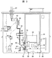
図3に、引出形回路遮断器を運転位置に固定した場合の配電盤を示す。 FIG. 3 shows the switchboard when the drawer-type circuit breaker is fixed at the operating position.
該図において、運転位置とは、配電盤主回路と引出形回路遮断器が接続され、引出形回路遮断器が、主回路に適切に電流を通電することができる位置のことを言う。 In this figure, the operation position refers to a position where the switchboard main circuit and the drawer-type circuit breaker are connected, and the drawer-type circuit breaker can appropriately energize the main circuit.
上述した引出可能な引出形回路遮断器が配電盤内で運転位置に固定されると、配電盤の上側主回路端子接続部64と引出形回路遮断器の上側主回路端子51が、また配電盤の下側主回路端子接続部63と引出形回路遮断器の下側主回路端子52がそれぞれ電気的に接続し、引出形回路遮断器の入切操作により主回路母線61、主回路導体62、下側主回路端子接続部63、引出形回路遮断器、上側主回路端子接続部64、電動断路器66、主回路ケーブル67から構成される主回路を流れる電流の投入、遮断が可能となる。
When the above-described drawable draw-out type circuit breaker is fixed in the operating position in the switchboard, the upper main
また、雷サージ等の過電圧からの主回路保護を目的とした避雷器69が、手動断路器68を介して主回路と電気的に接続されており、地絡、短絡故障時の主回路保護を目的としたΔI形計器用変流器65が主回路導体62に取付けられている。
A
図4に、引出形回路遮断器を断路位置に固定した場合の配電盤を示す。 FIG. 4 shows a switchboard when the drawer type circuit breaker is fixed at the disconnection position.
該図において、断路位置とは、配電盤主回路と引出形回路遮断器が、必要な絶縁距離を確保したときの引出形回路遮断器の位置のことを言う。 In this figure, the disconnection position means the position of the drawer-type circuit breaker when the switchboard main circuit and the drawer-type circuit breaker have secured the necessary insulation distance.
上述した引出可能な引出形回路遮断器が断路位置に固定されると、配電盤の上側主回路端子接続部64と引出形回路遮断器の上側主回路端子51、及び配電盤の下側主回路端子接続部63と引出形回路遮断器の下側主回路端子52は切り離されて電気的に絶縁されるため、引出形回路遮断器の入切状態に関わらず、上述した主回路には電流は流れない。
When the drawable draw-out type circuit breaker described above is fixed at the disconnection position, the upper main circuit
また、上側主回路端子接続部64と上側主回路端子51間及び下側主回路端子接続部63と下側主回路端子52間には、シャッター70が下りるため充電部の露出が防止され、人が充電部に触れられない構造となっている。
In addition, since the
そのため、引出形回路遮断器は、遮断器または配電盤の点検時や定時運用終了後には、この断路位置に固定されている。 Therefore, the draw-out type circuit breaker is fixed at this disconnection position when the circuit breaker or the switchboard is inspected or after the scheduled operation ends.
図5乃至7に、本発明のインターロック装置の一実施例を示す。図5乃至7は、インターロックピン2を、後述する引出形回路遮断器の固定位置に設定した場合のインターロック装置を示している。
5 to 7 show an embodiment of the interlock device of the present invention. 5 to 7 show the interlock device when the
該図に示す如く、上述した手動引外しボタン1は、固定式回路遮断器50の手動引外し機構部と連結している手動引外しロッド10と機械的に連結しており、この手動引外しボタン1を正面から押し込むと、手動引外しロッド10が固定式回路遮断器50の手動引外し機構部を動作させ、遮断器は切状態となる。
As shown in the figure, the above-described
また、インターロックピン2は、インターロックロッド3に取付けられており、台車34に固定されているインターロックピン金具5の正面中央にあるコの字形の穴(このコの字形の穴は、外部から見えるようになっている)の内部を移動することで、引出形回路遮断器の移動可能位置及び固定位置に移動することができる。
The
インターロックロッド3は丸棒で、インターロックピン金具5、台車34、インターロックロッド固定金具11にあけられた円形の穴を通過し、前後左右方向へは変位せず、昇降及び回転自在な構造であるが、インターロックピン金具5の正面中央のコの字形の穴と、インターロックピン2及びインターロックロッド3と手動引外しボタン1の干渉によって、可動範囲が制限されている。
The
インターロックピン2をインターロックピン金具5の正面中央にあるコの字形の穴の内部を移動して移動可能位置に設定した場合、インターロックロッド3は上方に、インターロックピン2をインターロックピン金具5の正面中央にあるコの字形の穴の内部を移動して固定位置に設定した場合、インターロックロッド3は下方に位置される。
When the
引出形回路遮断器を運転位置若しくは断路位置に配置してインターロックピン2を固定位置に設定した状態では、インターロックロッド3の下端部が、配電盤の床面に取付けられた複数個の遮断器固定用金具55の間で形成された空間に入ることで両者が干渉するため、引出形回路遮断器は、運転位置若しくは断路位置から動かすことができず、固定される。
In a state in which the draw-out type circuit breaker is arranged at the operation position or disconnection position and the
インターロックピン2を、インターロックピン金具5の正面中央にあるコの字形の穴の内部を移動して固定位置に設定すると、インターロックロッド3は、手動引外しボタン1よりも下方に位置するため、手動引外しボタン1とインターロックロッド3は干渉せず、手動引外しボタン1を自由に操作することができる。
When the
図8に、手動引外しボタン1を操作した状態のインターロック装置を示す。
FIG. 8 shows the interlock device in a state where the
インターロックピン2を固定位置に設定し、手動引外しボタン1を操作しない状態だと、インターロックロッド3と手動引外しボタン1が干渉するため、インターロックロッド3の上昇操作は阻止される。
When the
そこで、インターロックピン2を移動可能位置に設定、つまりインターロックロッド3の上昇操作をするためには、手動引外しボタン1を正面から押し込み、手動引外しボタン1とインターロックロッド3と干渉しないようにする必要がある。
Therefore, in order to set the
このとき、手動引外しボタン1が操作されるため、引出形回路遮断器を移動させるためには必ず切動作を行うこととなる。
At this time, since the
また、引出形回路遮断器を運転位置に挿入するとき及び運転位置から引出すときには、出し入れハンドル挿入口9に出し入れハンドルを挿入し、出し入れハンドル用金具7に出し入れハンドルを引っ掛ける必要がある。
Further, when the drawer type circuit breaker is inserted into the operation position or pulled out from the operation position, it is necessary to insert the insertion / removal handle into the insertion / removal handle insertion port 9 and to hook the insertion / removal handle onto the
インターロックピン2を固定位置に設定すると、インターロックロッド3に取付けられた金具8に出し入れハンドルが干渉するため、出し入れハンドルを出し入れハンドル用金具7に引っ掛けることができず、引出形回路遮断器の運転位置への挿入及び運転位置からの引出しが不可能になっている。
When the
図9乃至11は、インターロックピン2を、引出形回路遮断器の移動可能位置に設定した場合のインターロック装置を示している。
9 to 11 show the interlock device when the
該図に示す如く、インターロックピン2を、インターロックピン金具5の正面中央にあるコの字形の穴の内部を移動して移動可能位置に設定すると、インターロックロッド3は上方に位置される。
As shown in the figure, when the
引出形回路遮断器が運転位置、断路位置に位置しているとき以外は、遮断器固定用金具55とインターロックロッド3の干渉により、インターロックピン2を固定位置に設定することはできない。
The
この状態、即ち、インターロックピン2を移動可能位置に設定した状態では、手動引外しボタン1は、インターロックロッド3と干渉するため、常に押し込まれた状態を継続する。つまり、常に固定式回路遮断器50の手動引外し機構部へ手動引外し指令が与えられることになり、引出形回路遮断器は常に切状態となる。
In this state, that is, in a state where the
インターロックピン2を移動可能位置に設定した状態では、インターロックロッド3と配電盤の床面に取付けられた遮断器固定用金具55が干渉しないため、引出形回路遮断器は自由に移動させることができる。
In the state where the
また、インターロックピン2を固定位置に設定した場合は、前述のように、出し入れハンドル用金具7に出し入れハンドルを引っ掛けることが不可能であったが、インターロックピン2を移動可能位置に設定すると、インターロックロッド3に取付けられた金具8もインターロックロッド3と一緒に上方へ移動するため、出し入れハンドルと金具8は干渉せず、引出形回路遮断器の運転位置への挿入および運転位置からの引出しが可能である。
Further, when the
以上により、引出形回路遮断器は、配電盤内では運転位置、断路位置で確実に固定され、運転位置から引出形回路遮断器を移動させるとき、及び運転位置へ引出形回路遮断器を移動させるときは必ず切状態となる。 As described above, the drawer-type circuit breaker is securely fixed at the operation position and disconnection position in the switchboard, and when the drawer-type circuit breaker is moved from the operation position and when the drawer-type circuit breaker is moved to the operation position Is always turned off.
また、引出形回路遮断器が運転位置、断路位置以外に配置しているときは、入切操作が不可能、かつ切状態を継続する。 Further, when the drawer type circuit breaker is arranged at a position other than the operation position and the disconnection position, the on / off operation is impossible and the disconnection state is continued.
これにより、電気回路の電流を投入、遮断するための引出形回路遮断器の配電盤内における適切な位置での固定は勿論、入状態の引出形回路遮断器の振動によるせり出し、誤引出しおよび誤挿入に起因するアークによる機器の損傷、変電所火災等の重大事故のポテンシャルを排除することができる。 As a result, the drawer type circuit breaker for turning on / off the electric circuit current is fixed at an appropriate position in the switchboard, as well as protruding, misdrawing and erroneous insertion due to vibration of the drawn type circuit breaker in the on state. The potential for serious accidents such as equipment damage due to arcs and substation fires can be eliminated.
1…手動引外しボタン、2…インターロックピン、3…インターロックロッド、4…金具、5…インターロックピン金具、6…リミットスイッチ、7…出し入れハンドル用金具、8…金具、9…出し入れハンドル挿入口、10…手動引外しロッド、11…インターロックロッド固定金具、12…ばね、30…正面パネル31…移動用把手、32…回数計、33…制御プラグ34…台車、35…フレーム、36…車輪、50…固定式回路遮断器、51…上側主回路端子、52…下側主回路端子、53…上側主回路導体、54…下側主回路導体、55…遮断器固定用金具、61…主回路母線、62…主回路導体、63…下側主回路端子接続部、64…上側主回路端子接続部、65…ΔI形計器用変流器、66…電動断路器、67…主回路ケーブル、68…手動断路器、69…避雷器、70…シャッター。
DESCRIPTION OF
Claims (6)
前記インターロック装置は、引出形回路遮断器の引外し機構部と連結した引外しボタンと、昇降自在に配置されたインターロックロッドとを備え、
前記インターロックロッドは、該インターロックロッドと一体に構成され、該インターロックロッドを前記引出形回路遮断器の固定位置及び移動可能位置に移動させるインターロックピンを備え、かつ、前記インターロックピンは、前記移動装置に固定されているインターロックピン金具の正面に形成されているコの字形の穴を移動することで、引出形回路遮断器の移動可能位置及び固定位置に移動するものであり、
前記引外しボタンを操作して引出形回路遮断器を切状態にしない限り、前記引外しボタンにより機械的に前記インターロックロッドの上昇操作が阻止されることで、配電盤床面若しくは配電盤床面に固定された部材と前記インターロックロッドが機械的に干渉し、配電盤内の所定の位置で前記引出形回路遮断器を固定すると共に、前記インターロックピン金具の正面に形成されているコの字形の穴の上部に前記インターロックロッドが位置しているとき、前記引外しボタンと前記インターロックロッドが機械的に干渉することで前記引外しボタンが常に操作された状態となり、切状態を継続することを特徴とする引出形回路遮断器。 A main contact for turning on and off the main circuit, a driving device for driving the main contact, a main circuit energization part for energizing the main circuit current, the main circuit energization part and the main circuit in the switchboard A connecting portion for making the detachable connection, a moving device for moving the drawer-type circuit breaker, an interlock device for fixing the drawer-type circuit breaker housed in the switchboard at a predetermined position, and In a draw-out type circuit breaker with
The interlock device includes a trip button connected to a trip mechanism of a drawer type circuit breaker, and an interlock rod arranged to be movable up and down.
The interlock rod is configured integrally with the interlock rod, and includes an interlock pin that moves the interlock rod to a fixed position and a movable position of the drawer-type circuit breaker, and the interlock pin is , By moving a U-shaped hole formed on the front surface of the interlock pin fitting fixed to the moving device, it moves to a movable position and a fixed position of the drawer type circuit breaker,
Unless the pull-out type circuit breaker is turned off by operating the trip button, the trip button mechanically prevents the interlock rod from being lifted, so that the switchboard floor surface or the switchboard floor surface A fixed member and the interlock rod mechanically interfere to fix the drawer-type circuit breaker at a predetermined position in the switchboard, and a U-shape formed on the front surface of the interlock pin fitting. When the interlock rod is located in the upper part of the hole, the trip button and the interlock rod mechanically interfere with each other so that the trip button is always operated and the cut state is continued. Drawer type circuit breaker.
前記インターロックピン金具の正面に形成されているコの字形の穴の下部に前記インターロックロッドが位置しているときは、前記引外しボタンは、前記インターロックロッドと機械的に干渉していないことを特徴とする引出形回路遮断器。 The drawer-type circuit breaker according to claim 1 ,
When the interlock rod at the bottom of the hole before Symbol co formed in front of the interlock pin fitting shape is positioned, the tripping button, the interlock rod and are mechanically interfere Drawer type circuit breaker characterized by not .
前記インターロックロッドは、配電盤床面若しくは配電盤床面に固定された部材と干渉することにより、配電盤主回路と前記引出形回路遮断器の接続部が接続された運転位置、配電盤主回路と遮断器接続部が必要な絶縁距離を確保した断路位置及び配電盤外でのみ下方に位置することを特徴とする引出形回路遮断器。 The drawer-type circuit breaker according to claim 1 or 2 ,
The interlock rod interferes with a switchboard floor surface or a member fixed to the switchboard floor surface, thereby operating a connection position of the switchboard main circuit and the connection part of the drawer type circuit breaker, the switchboard main circuit and the circuit breaker. A draw-out type circuit breaker characterized in that the connection part is located below the disconnection position where the necessary insulation distance is secured and outside the switchboard .
引出形回路遮断器の正面には、前記引外しボタン、インターロックロッド、インターロックピンが配置されていることを特徴とする引出形回路遮断器。 The drawer type circuit breaker according to any one of claims 1 to 3 ,
The drawer type circuit breaker is characterized in that the trip button, the interlock rod, and the interlock pin are arranged in front of the drawer type circuit breaker.
前記引出形回路遮断器は、請求項1乃至4のいずれかに記載の引出形回路遮断器であることを特徴とする配電盤。 The main circuit cable main circuit conductor, main circuit bus, and main circuit terminal connection installed in the panel are electrically detachable from the main circuit terminal connection and can be moved to the operating position and disconnection position. In the switchboard that houses the drawer-type circuit breaker
5. The switchboard according to claim 1, wherein the drawer-type circuit breaker is the drawer-type circuit breaker according to claim 1 .
前記主回路端子接続部と前記引出形回路遮断器の接続端子との電気的な接続が開放されたときに、両者の間を塞ぐシャッターを備えていることを特徴とする配電盤。 The switchboard according to claim 5 ,
A switchboard comprising a shutter that closes between the main circuit terminal connection portion and the connection terminal of the lead-out type circuit breaker when the electrical connection is opened.
Priority Applications (9)
| Application Number | Priority Date | Filing Date | Title |
|---|---|---|---|
| JP2011050897A JP5364118B2 (en) | 2011-03-09 | 2011-03-09 | Drawer type circuit breaker and switchboard |
| TW100148608A TWI469176B (en) | 2011-03-09 | 2011-12-26 | Lead-out circuit breaker and switchboard |
| SG2012007696A SG184630A1 (en) | 2011-03-09 | 2012-02-02 | Interlock device of draw-out type circuit breaker, draw-out type circuit breaker, and power distribution board |
| IN290DE2012 IN2012DE00290A (en) | 2011-03-09 | 2012-02-02 | |
| US13/367,395 US8796570B2 (en) | 2011-03-09 | 2012-02-07 | Interlock device of draw-out type circuit breaker, draw-out type circuit breaker, and power distribution board |
| MYPI2012000548A MY155673A (en) | 2011-03-09 | 2012-02-09 | Interlock device of draw-out type circuit breaker,draw-out type circuit breaker, and power distribution board |
| KR1020120013182A KR101291835B1 (en) | 2011-03-09 | 2012-02-09 | Interlock apparatus for draw-out type circuit breaker, draw-out type circuit breaker and switchboard |
| EP12154884.6A EP2498354B1 (en) | 2011-03-09 | 2012-02-10 | Interlock device of draw-out type circuit breaker, draw-out type circuit breaker, and power distribution board |
| CN201210048365.2A CN102684093B (en) | 2011-03-09 | 2012-02-28 | The interlock of drawer type contactor, drawer type contactor and distribution board |
Applications Claiming Priority (1)
| Application Number | Priority Date | Filing Date | Title |
|---|---|---|---|
| JP2011050897A JP5364118B2 (en) | 2011-03-09 | 2011-03-09 | Drawer type circuit breaker and switchboard |
Publications (2)
| Publication Number | Publication Date |
|---|---|
| JP2012191685A JP2012191685A (en) | 2012-10-04 |
| JP5364118B2 true JP5364118B2 (en) | 2013-12-11 |
Family
ID=45562236
Family Applications (1)
| Application Number | Title | Priority Date | Filing Date |
|---|---|---|---|
| JP2011050897A Active JP5364118B2 (en) | 2011-03-09 | 2011-03-09 | Drawer type circuit breaker and switchboard |
Country Status (9)
| Country | Link |
|---|---|
| US (1) | US8796570B2 (en) |
| EP (1) | EP2498354B1 (en) |
| JP (1) | JP5364118B2 (en) |
| KR (1) | KR101291835B1 (en) |
| CN (1) | CN102684093B (en) |
| IN (1) | IN2012DE00290A (en) |
| MY (1) | MY155673A (en) |
| SG (1) | SG184630A1 (en) |
| TW (1) | TWI469176B (en) |
Families Citing this family (14)
| Publication number | Priority date | Publication date | Assignee | Title |
|---|---|---|---|---|
| JP6364741B2 (en) * | 2013-10-28 | 2018-08-01 | 富士電機株式会社 | Unit storage device |
| CN103618229B (en) * | 2013-11-26 | 2016-05-11 | 芜湖金牛电气股份有限公司 | A kind of switch cubicle of manual control |
| US9425590B2 (en) * | 2013-12-16 | 2016-08-23 | Lsis Co., Ltd. | Withdrawable-type circuit breaker |
| CN104409249A (en) * | 2014-10-28 | 2015-03-11 | 洛阳龙羽电气设备有限公司 | Linkage switch of high-voltage breaker cabinet for box type transformer station |
| KR101640712B1 (en) | 2015-04-20 | 2016-07-19 | 엘에스산전 주식회사 | Vaccum circuit braker |
| US10027096B2 (en) * | 2016-02-23 | 2018-07-17 | General Electric Company | Shutter interlock devices, systems, and methods of use thereof |
| KR101809822B1 (en) * | 2016-03-11 | 2017-12-15 | 엘에스산전 주식회사 | Arc Eliminator |
| JP6293393B1 (en) * | 2017-06-13 | 2018-03-14 | 三菱電機株式会社 | Switching device moving mechanism |
| KR102281954B1 (en) * | 2019-12-17 | 2021-07-26 | 엘에스일렉트릭(주) | Plug interlock device for circuit breaker |
| CN111192776A (en) * | 2020-02-24 | 2020-05-22 | 正泰电气股份有限公司 | Mechanical interlocking device of isolating switch and circuit breaker |
| KR102693726B1 (en) * | 2020-11-27 | 2024-08-12 | 미쓰비시덴키 가부시키가이샤 | Protective shutters and closed switchboards |
| CN112601409B (en) * | 2020-12-03 | 2022-01-28 | 无锡国悦电子科技有限公司 | Semiconductor various-component flow control cabinet with wire arranging structure |
| US11979006B2 (en) * | 2021-01-13 | 2024-05-07 | Rockwell Automation Technologies, Inc. | Two-step interlock for modules in a motor control center |
| KR20230149017A (en) * | 2022-04-19 | 2023-10-26 | 엘에스일렉트릭(주) | Pull-out apparatus |
Family Cites Families (15)
| Publication number | Priority date | Publication date | Assignee | Title |
|---|---|---|---|---|
| US2673260A (en) * | 1949-12-20 | 1954-03-23 | Gen Electric | Switchgear carriage orbital cam racking and interlocking mechanism |
| JPS57147829A (en) * | 1981-03-06 | 1982-09-11 | Tokyo Shibaura Electric Co | Vacuum breaker |
| DE3542979C2 (en) * | 1985-12-05 | 1995-12-21 | Sachsenwerk Ag | Partitioned control cabinet |
| GB8721964D0 (en) | 1987-09-18 | 1987-10-28 | Shell Int Research | Multitube reactor |
| JPH01111436U (en) * | 1988-01-22 | 1989-07-27 | ||
| KR940001118B1 (en) * | 1990-06-21 | 1994-02-14 | 미쯔비시 덴끼 가부시기가이샤 | Control circuit locking device for drawout type circuit breaker |
| US5623135A (en) | 1995-09-11 | 1997-04-22 | Kabushiki Kaisha Aichi Denki Seisakusho | Power source switching device with plural interlocking elements |
| JPH10210611A (en) * | 1997-01-23 | 1998-08-07 | Nissin Electric Co Ltd | Interlock equipment of breaker |
| JPH11164422A (en) | 1997-11-28 | 1999-06-18 | Yaskawa Electric Corp | Interlock equipment for pull-out type circuit breaker |
| EP1416503B1 (en) | 2002-10-30 | 2013-09-18 | Hitachi, Ltd. | Solenoid-operated switching device and control device for electromagnet |
| JP3763094B2 (en) * | 2002-10-30 | 2006-04-05 | 株式会社日立製作所 | Electromagnetic operation device |
| JP4222105B2 (en) * | 2003-05-27 | 2009-02-12 | パナソニック電工株式会社 | Circuit breaker |
| JP4332746B2 (en) | 2005-11-07 | 2009-09-16 | 株式会社日立製作所 | Electromagnetic operation device |
| US7881044B2 (en) * | 2009-06-04 | 2011-02-01 | Eaton Corporation | Electrical switching apparatus and dampening mechanism therefor |
| JP5275301B2 (en) * | 2010-08-12 | 2013-08-28 | 株式会社日立製作所 | Air circuit breaker |
-
2011
- 2011-03-09 JP JP2011050897A patent/JP5364118B2/en active Active
- 2011-12-26 TW TW100148608A patent/TWI469176B/en not_active IP Right Cessation
-
2012
- 2012-02-02 SG SG2012007696A patent/SG184630A1/en unknown
- 2012-02-02 IN IN290DE2012 patent/IN2012DE00290A/en unknown
- 2012-02-07 US US13/367,395 patent/US8796570B2/en not_active Expired - Fee Related
- 2012-02-09 MY MYPI2012000548A patent/MY155673A/en unknown
- 2012-02-09 KR KR1020120013182A patent/KR101291835B1/en active IP Right Grant
- 2012-02-10 EP EP12154884.6A patent/EP2498354B1/en not_active Not-in-force
- 2012-02-28 CN CN201210048365.2A patent/CN102684093B/en not_active Expired - Fee Related
Also Published As
| Publication number | Publication date |
|---|---|
| TWI469176B (en) | 2015-01-11 |
| EP2498354A2 (en) | 2012-09-12 |
| US20120228096A1 (en) | 2012-09-13 |
| IN2012DE00290A (en) | 2015-04-10 |
| CN102684093A (en) | 2012-09-19 |
| KR101291835B1 (en) | 2013-07-31 |
| SG184630A1 (en) | 2012-10-30 |
| CN102684093B (en) | 2015-10-28 |
| EP2498354B1 (en) | 2016-08-24 |
| US8796570B2 (en) | 2014-08-05 |
| JP2012191685A (en) | 2012-10-04 |
| MY155673A (en) | 2015-11-13 |
| EP2498354A3 (en) | 2013-12-25 |
| TW201243897A (en) | 2012-11-01 |
| KR20120103442A (en) | 2012-09-19 |
Similar Documents
| Publication | Publication Date | Title |
|---|---|---|
| JP5364118B2 (en) | Drawer type circuit breaker and switchboard | |
| KR101658541B1 (en) | Withdrawable interlock device of vacuum circuit breaker | |
| EP2228878A2 (en) | Apparatus for preventing withdrawing or inserting of carriage in circuit breaker | |
| EP3118954B1 (en) | Structure of switchgear with arc eliminator | |
| TW201145737A (en) | Switchgear | |
| KR101686361B1 (en) | Vacuum circuit breaker | |
| JP2011078273A (en) | Working carriage for switchboard, and switchboard | |
| EP3161914B1 (en) | Motor control center with an automatic fused grounding of the load terminals | |
| JP2009171774A (en) | Shielding device of switch gear | |
| US20140211377A1 (en) | Removable contactor drawer | |
| KR200489519Y1 (en) | plug Interlock Device of Vacuum Circuit Breaker | |
| KR101251604B1 (en) | Motor control center | |
| KR101117973B1 (en) | Withdrawable apparatus for vacuum circuit breaker | |
| KR101071920B1 (en) | Slim Type Overload and Earth Leakage Circuit Breaker | |
| JP6632402B2 (en) | Switchgear | |
| JP4355601B2 (en) | How to update magnetic circuit breaker | |
| KR102293745B1 (en) | Drawable truck of ultra fast earthing switch with epoxy insulator | |
| KR101594868B1 (en) | Interlock Device of Vacuum Circuit Breaker | |
| KR20110090124A (en) | Device for preventing of earthing switch | |
| KR101689947B1 (en) | Vaccum circuit braker having code plate | |
| JPS5936484B2 (en) | Breaker with earthing device | |
| KR20170006143A (en) | Resistor installed in the neighborhood distribution circuit breaker designed for electrical distribution boxes |
Legal Events
| Date | Code | Title | Description |
|---|---|---|---|
| A621 | Written request for application examination |
Free format text: JAPANESE INTERMEDIATE CODE: A621 Effective date: 20121109 |
|
| A977 | Report on retrieval |
Free format text: JAPANESE INTERMEDIATE CODE: A971007 Effective date: 20130412 |
|
| A131 | Notification of reasons for refusal |
Free format text: JAPANESE INTERMEDIATE CODE: A131 Effective date: 20130423 |
|
| A521 | Written amendment |
Free format text: JAPANESE INTERMEDIATE CODE: A523 Effective date: 20130613 |
|
| TRDD | Decision of grant or rejection written | ||
| A01 | Written decision to grant a patent or to grant a registration (utility model) |
Free format text: JAPANESE INTERMEDIATE CODE: A01 Effective date: 20130903 |
|
| A61 | First payment of annual fees (during grant procedure) |
Free format text: JAPANESE INTERMEDIATE CODE: A61 Effective date: 20130906 |
|
| R150 | Certificate of patent or registration of utility model |
Ref document number: 5364118 Country of ref document: JP Free format text: JAPANESE INTERMEDIATE CODE: R150 Free format text: JAPANESE INTERMEDIATE CODE: R150 |
|
| S111 | Request for change of ownership or part of ownership |
Free format text: JAPANESE INTERMEDIATE CODE: R313111 |
|
| R350 | Written notification of registration of transfer |
Free format text: JAPANESE INTERMEDIATE CODE: R350 |