JP5363503B2 - Casting mold for forming biomedical devices including ophthalmic devices - Google Patents
Casting mold for forming biomedical devices including ophthalmic devices Download PDFInfo
- Publication number
- JP5363503B2 JP5363503B2 JP2010540813A JP2010540813A JP5363503B2 JP 5363503 B2 JP5363503 B2 JP 5363503B2 JP 2010540813 A JP2010540813 A JP 2010540813A JP 2010540813 A JP2010540813 A JP 2010540813A JP 5363503 B2 JP5363503 B2 JP 5363503B2
- Authority
- JP
- Japan
- Prior art keywords
- mold
- mold section
- flange
- optical surface
- casting mold
- Prior art date
- Legal status (The legal status is an assumption and is not a legal conclusion. Google has not performed a legal analysis and makes no representation as to the accuracy of the status listed.)
- Expired - Fee Related
Links
Images


Classifications
-
- B—PERFORMING OPERATIONS; TRANSPORTING
- B29—WORKING OF PLASTICS; WORKING OF SUBSTANCES IN A PLASTIC STATE IN GENERAL
- B29D—PRODUCING PARTICULAR ARTICLES FROM PLASTICS OR FROM SUBSTANCES IN A PLASTIC STATE
- B29D11/00—Producing optical elements, e.g. lenses or prisms
- B29D11/00009—Production of simple or compound lenses
- B29D11/00038—Production of contact lenses
- B29D11/00125—Auxiliary operations, e.g. removing oxygen from the mould, conveying moulds from a storage to the production line in an inert atmosphere
-
- B—PERFORMING OPERATIONS; TRANSPORTING
- B29—WORKING OF PLASTICS; WORKING OF SUBSTANCES IN A PLASTIC STATE IN GENERAL
- B29C—SHAPING OR JOINING OF PLASTICS; SHAPING OF MATERIAL IN A PLASTIC STATE, NOT OTHERWISE PROVIDED FOR; AFTER-TREATMENT OF THE SHAPED PRODUCTS, e.g. REPAIRING
- B29C33/00—Moulds or cores; Details thereof or accessories therefor
- B29C33/20—Opening, closing or clamping
-
- B—PERFORMING OPERATIONS; TRANSPORTING
- B29—WORKING OF PLASTICS; WORKING OF SUBSTANCES IN A PLASTIC STATE IN GENERAL
- B29D—PRODUCING PARTICULAR ARTICLES FROM PLASTICS OR FROM SUBSTANCES IN A PLASTIC STATE
- B29D11/00—Producing optical elements, e.g. lenses or prisms
- B29D11/00009—Production of simple or compound lenses
- B29D11/0048—Moulds for lenses
- B29D11/005—Moulds for lenses having means for aligning the front and back moulds
-
- Y—GENERAL TAGGING OF NEW TECHNOLOGICAL DEVELOPMENTS; GENERAL TAGGING OF CROSS-SECTIONAL TECHNOLOGIES SPANNING OVER SEVERAL SECTIONS OF THE IPC; TECHNICAL SUBJECTS COVERED BY FORMER USPC CROSS-REFERENCE ART COLLECTIONS [XRACs] AND DIGESTS
- Y10—TECHNICAL SUBJECTS COVERED BY FORMER USPC
- Y10S—TECHNICAL SUBJECTS COVERED BY FORMER USPC CROSS-REFERENCE ART COLLECTIONS [XRACs] AND DIGESTS
- Y10S425/00—Plastic article or earthenware shaping or treating: apparatus
- Y10S425/808—Lens mold
Landscapes
- Engineering & Computer Science (AREA)
- Mechanical Engineering (AREA)
- Health & Medical Sciences (AREA)
- Manufacturing & Machinery (AREA)
- Ophthalmology & Optometry (AREA)
- Moulds For Moulding Plastics Or The Like (AREA)
- Casting Or Compression Moulding Of Plastics Or The Like (AREA)
- Eyeglasses (AREA)
Abstract
Description
本発明はバイオメディカルデバイスの形成に関し、そしてより詳細には、光学表面を有する眼科デバイスの形成のためのモールドアセンブリに関する。前方モールドセクション及び後方モールドセクションを有するキャスティングモールドであって、それらのモールドセクションが1つのモールドセクション上のリブと第二のモールドセクション上の環状ショルダーとの間に締まりばめによって操作可能に係合されうるキャスティングモールドを提供する。 The present invention relates to the formation of biomedical devices, and more particularly to mold assemblies for the formation of ophthalmic devices having optical surfaces. A casting mold having a front mold section and a rear mold section, wherein the mold sections are operably engaged by an interference fit between a rib on one mold section and an annular shoulder on a second mold section. A casting mold is provided.
コンタクトレンズなどの眼科デバイスを含むバイオメディカルデバイスを製造するための1つの方法はキャストモールディングである。コンタクトレンズのキャストモールディイングは、少なくとも2つのキャスティングモールドセクションが組み合わされて形成されたキャスティングモールドキャビティー中に、モノマーなどの重合性レンズ材料の硬化性混合物を堆積させ、その混合物を硬化させ、キャスティングモールドセクションを分解し、そして成形されたレンズを取り出すことを含む。成形後の処理工程、たとえば、ヒドロゲルレンズの場合の水和も用いることができる。代表的なキャストモールディング法は米国特許第5,271,875号明細書(Appletonら)、米国特許第4,197,266号明細書(Clarkら)、米国特許第4,208,364号明細書(Shepherd)、米国特許第4,865,779号明細書(Ihnら)、米国特許第4,955,580号明細書(Sedenら)、米国特許第5,466,147号明細書(Appletonら)及び米国特許第5,143,660号明細書(Hamiltonら)に記載されている。 One method for manufacturing biomedical devices, including ophthalmic devices such as contact lenses, is cast molding. Cast molding of contact lenses involves depositing a curable mixture of a polymerizable lens material, such as a monomer, in a casting mold cavity formed by combining at least two casting mold sections, curing the mixture, Disassembling the casting mold section and removing the molded lens. Processing steps after molding, such as hydration in the case of hydrogel lenses, can also be used. Typical cast molding methods are described in US Pat. No. 5,271,875 (Appleton et al.), US Pat. No. 4,197,266 (Clark et al.), US Pat. No. 4,208,364. (Shepherd), US Pat. No. 4,865,779 (Ihn et al.), US Pat. No. 4,955,580 (Seden et al.), US Pat. No. 5,466,147 (Appleton et al.). ) And US Pat. No. 5,143,660 (Hamilton et al.).
このように、モールドの形状、特に、モールドの光学表面は得られるレンズの表面を少なくとも部分的に決定する。成形されたバイオメディカルデバイスでは有意な数の光学欠陥が補正されうるが、多くの眼科デバイスは2つのモールドハーフを要求するので、キャスティングモールドの形状を最適化する必要性がある。 Thus, the shape of the mold, particularly the optical surface of the mold, at least partially determines the surface of the resulting lens. While a molded biomedical device can correct a significant number of optical defects, many ophthalmic devices require two mold halves, so there is a need to optimize the shape of the casting mold.
発明の簡単な要旨
バイオメディカルデバイスを形成するための、ある体積の硬化性液体を保持するための本キャスティングモールドは第一の光学表面及び放射状に延在している第一のフランジを有する第一のモールドセクション、第二の光学表面及び放射状に延在している第二のフランジを有する第二のモールドセクションを含み、その第一のモールドセクション及び第二のモールドセクションはその間にモールドキャビティーを画定するように共働的に係合するようにサイズ決めされており、そのモールドキャビティーは光学軸及びシールされた周囲縁を有し、そのモールドキャビティーは光学軸に沿って所与の長さを占め、第一のフランジ及び第二のフランジのうちの一方は複数の放射状に延在しているリブを含み、各リブは光学軸から間隔を開けて離れた外側末端を有し、そして第一のフランジ及び第二のフランジのうちのもう一方は複数のリブと係合するようにサイズ決めされた軸方向に延在しているショルダーを含む。1つの形態において、リブは、リブの部分が可塑的に変形されるようにして、対応する複数の接触点でショルダーと接触する。
BRIEF SUMMARY OF THE INVENTION A casting mold for holding a volume of a curable liquid to form a biomedical device includes a first optical surface and a first radially extending flange. A second mold section having a second optical surface and a radially extending second flange, the first mold section and the second mold section having a mold cavity therebetween. Sized to cooperatively engage, the mold cavity having an optical axis and a sealed peripheral edge, the mold cavity being a given length along the optical axis One of the first flange and the second flange includes a plurality of radially extending ribs, each rib extending from the optical axis An axially extending shoulder having a spaced apart outer end and the other of the first and second flanges sized to engage a plurality of ribs including. In one form, the rib contacts the shoulder at a plurality of corresponding contact points such that the rib portion is plastically deformed.
本キャスティングモールドは、バイオメディカルデバイスを形成するためのある体積の硬化性液体を保持することができ、そして、第一のモールドセクション中にある量の硬化性液体を配置すること、ここで、その第一のモールドセクションは光学軸を含む光学表面を有し、その光学表面は硬化性液体と接触し、その第一のモールドセクションは放射状に突出したフランジを含み、そのフランジは光学軸に沿った光学表面から間隔を開けて離れたショルダーを有する、及び、その第一のモールドセクションと第二のモールドセクションとを接触させて、モールドキャビティー中に硬化性液体の少なくとも一部を保持すること、ここで、その第二のモールドセクションは光学軸に対して放射状に延在している複数のリブを有し、そのリブの外側末端がショルダーと係合して変形される、によって用いられることができる。 The casting mold can hold a volume of curable liquid to form a biomedical device and place an amount of curable liquid in a first mold section, where the The first mold section has an optical surface that includes an optical axis, the optical surface is in contact with a curable liquid, the first mold section includes a radially projecting flange, and the flange is along the optical axis. Having a shoulder spaced from the optical surface and contacting the first mold section and the second mold section to retain at least a portion of the curable liquid in the mold cavity; Here, the second mold section has a plurality of ribs extending radially with respect to the optical axis, and the outside of the ribs. End is deformed to engage the shoulder, it can be used by.
凸状の第一の光学表面、放射状に延在している第一のフランジ及び第一のフランジの1つの面から軸方向に延在しかつ放射状に延在して自由端で終結している複数のリブを有する第一のモールドセクションを提供すること、凹状の第二の光学表面及び放射状に延在している第二のフランジを有し、その第二の光学表面が直柱状壁を含み、また、その第二のフランジから軸方向に延在しているショルダーを有する、第二のモールドセクションを提供すること、ある量の硬化性液体を第二の光学表面上に堆積させること、及び、上記の複数のリブの各々の自由端と上記のショルダーとを接触させ、直柱状壁の一部が第一の光学表面と接触しているようにして第一のモールドセクション及び第二のモールドセクションを係合させ、第一の光学表面と第二の光学表面との間にシールされたモールドキャビティーを画定することによる、キャスティングモールド中の保持された体積の硬化性液体からバイオメディカルデバイスを形成するための方法が提供される。 A convex first optical surface, a radially extending first flange, and extending axially from one surface of the first flange and extending radially and terminating at a free end Providing a first mold section having a plurality of ribs, having a concave second optical surface and a radially extending second flange, the second optical surface comprising a columnar wall Providing a second mold section having a shoulder extending axially from the second flange, depositing an amount of curable liquid on the second optical surface, and The first mold section and the second mold are such that the free ends of the ribs and the shoulder are in contact with each other so that a part of the straight columnar wall is in contact with the first optical surface. Engage the section with the first optical surface According to define a sealed mold cavity between the second optical surface, a method for forming a biomedical device from the curable liquid volume retained in the casting mold is provided.
凸状の第一の光学表面、及び、第一の非光学表面中の逆テーパーを有する、第一のモールドセクションを射出成形すること、凹状の第二の光学表面、及び、第二の非光学表面中の逆テーパーを有する、第二のモールドセクションを射出成形すること、前記第二の光学表面上にある体積の硬化性液体を堆積させること、及び、前記第一のモールドセクション及び第二のモールドセクションを係合させて、前記第一のモールドセクション及び第二のモールドセクションの間に前記硬化性液体を保持する、シールされたモールドキャビティーを画定することによる、キャスティングモールド中の保持された体積の硬化性液体からバイオメディカルデバイスを形成するための別の方法も提供される。 Injection molding a first mold section having a convex first optical surface and a reverse taper in the first non-optical surface, a concave second optical surface, and a second non-optical Injection molding a second mold section having a reverse taper in the surface, depositing a volume of curable liquid on the second optical surface, and the first mold section and the second mold section Retained in the casting mold by engaging a mold section to define a sealed mold cavity that retains the curable liquid between the first mold section and the second mold section. Another method for forming a biomedical device from a volume of curable liquid is also provided.
凸状の第一の光学表面及び放射状に延在している第一のフランジ、該第一のフランジの1つの面から軸方向に延在しかつ放射状に延在して自由末端で終結している複数のリブを有する、第一のモールドセクションを提供すること、凹状の第二の光学表面及び放射状に延在している第二のフランジ、該第二のフランジの1つの面から軸方向に延在しているショルダーを有する第二のモールドセクションを提供すること、及び、前記第一のモールドセクション及び第二のモールドセクションを、(i)前記第一の光学表面及び第二の光学表面の間のシールされた縁、及び(ii)前記複数のリブの自由末端及びショルダーの間の複数の接触点からなる係合によって係合させ、モールドキャビティーを形成することによる、キャスティングモールド中の保持された体積の硬化性液体からバイオメディカルデバイスを形成するための方法もさらに想定される。 A convex first optical surface and a radially extending first flange, extending axially from one face of the first flange and extending radially and terminating at a free end Providing a first mold section having a plurality of ribs, a concave second optical surface and a radially extending second flange, axially from one face of the second flange Providing a second mold section having an extending shoulder; and (i) providing the first mold section and the second mold section with (i) the first optical surface and the second optical surface; Retention in the casting mold by engaging a seal edge between and (ii) a plurality of contact points between the free ends and shoulders of the plurality of ribs to form a mold cavity The Further contemplated is a method for forming a biomedical device from a defined volume of curable liquid.
添付の図面は本発明のさらなる理解を提供するために含まれ、そして本明細書中に取り込み、そして本明細書の一部を構成している。図面は必ずしも寸法通りではなく、様々な要素のサイズは明確さのために変形されていることがある。図面は本発明の1つ又はそれ以上の実施形態を例示し、そして記述は本発明の原理及び動作を説明するように機能する。 The accompanying drawings are included to provide a further understanding of the invention, and are incorporated in and constitute a part of this specification. The drawings are not necessarily to scale, and the sizes of the various elements may be varied for clarity. The drawings illustrate one or more embodiments of the invention, and the description serves to explain the principles and operations of the invention.
図1、2、13及び14を参照すると、代表的なキャスティングモールド10が示されている。キャスティングモールド10は眼科デバイスを含むあらゆる種類のバイオメディカルデバイスを形成するように構成されてよく、眼科デバイスとしては、限定するわけではないが、眼内レンズ(IOL)インプラント、コンタクトレンズ、人工角膜移植、角膜輪、角膜内レンズ(Corneal Inlay)などが挙げられる。説明の目的のために、キャスティングモールド10を図3に示すコンタクトレンズ20の形成について示している。コンタクトレンズ20についてのキャスティングモールド10の説明においても、コンタクトレンズはあらゆる種類の構造体であることができるが、コンタクトレンズとしては、限定するわけではないが、球形レンズ、円環状レンズ又は多焦点レンズが挙げられる。
With reference to FIGS. 1, 2, 13, and 14, a
コンタクトレンズ20は、凸状光学前方表面22及び凹状光学後方表面24を含み、各表面は体との接触に適合するように構成されている。
図1、2、13及び14に示す形態において、キャスティングモールド10は前方モールドセクション30及び後方モールドセクション70を含む。前方モールドセクション30はしばしば前方レンズ曲面もしくはプレフォームと称され、そして後方モールドセクション70はしばしば後方レンズ曲面もしくはプレフォームと称される。
In the form shown in FIGS. 1, 2, 13 and 14, the casting
図9及び14において見られるとおり、前方モールドセクション30及び後方モールドセクション70は光学軸OAを有するモールドキャビティー13を形成する。
As seen in FIGS. 9 and 14, the
前方モールドセクション30は得られるコンタクトレンズ20の前方凸状光学表面を形成する。詳細には、前方モールドセクション30は凹状光学表面32及び反対側の非光学表面34を有する中央曲面領域を含む。
The
本明細書中に使用されるときに、用語「光学品質」又は「光学表面」は光学表面を形成するのに十分に滑らかであるモールド表面であり、それが最終的にコンタクトレンズ20などの眼科デバイスの表面を形成するモールド表面を意味する。たとえば、製造されるレンズは、形成されたレンズ表面を機械加工し又はポリッシュする必要なく目の中に配置するのに適する。すなわち、目と接触するのに適するデバイスを提供するために、さらなる表面仕上げは要求されない。
As used herein, the term “optical quality” or “optical surface” is a mold surface that is sufficiently smooth to form an optical surface, which ultimately results in an ophthalmology such as
凹状光学品質表面32はキャスティングモールド10中で製造されるコンタクトレンズ20の前方表面22の寸法、好ましくはそのような倍率を持っている。凹状光学表面32は光学軸OAに対して相対的に一般に決まることができる。凹状光学表面32は周囲頂部又は縁36、たとえば、直柱状(筒型)壁で終わっており、それは光学軸OAに対して一般に平行である。
The concave
前方モールドセクション30は凹状光学品質表面32の周囲頂部36から延在している放射状に突出しているフランジ40を含む。1つの構造体において、フランジ40は凹状光学表面32の直柱状壁36から垂直に(そして、そのため、光学軸にほぼ垂直に)延在し、周囲縁42で終結している。フランジ40は光学軸OAに同心として示されているが、フランジは光学軸に対して非対称であることができることが理解される。フランジ40は放射状に突出しているタブ58を含むことができ、タブは光学軸OAに対して前方モールドセクション30を配向させる形態である。さらに、タブ58はコンタクトレンズ20の形成の後にモールドセクションを脱キャッピングし又は分離するのに使用されるような形態であることができる。
The
1つの形態において、フランジ40は凹状光学品質表面32の直柱状壁36及び周囲縁42を半径方向に介在して環状ショルダー(又はステップ)44を含む。このように、ショルダー44はフランジ40を、環状平面底面シェルフ46及び環状平面上面シェルフ48を含む。フランジ40の底面シェルフ46は直柱状壁36との交線において直柱状壁36に垂直であり、そして光学軸OAに対して垂直に延在している。上面シェルフ48は光学軸OAに対して垂直に延在している。
In one form, the
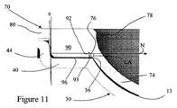
図9〜11を参照し、ショルダー44は凹状光学表面32から離れるように光学軸OAに沿って延在している。すなわち、ショルダー44及び凹状光学表面32は光学軸OAの共通部分には存在しない。ショルダー44は一般には光学軸OAに対して平行に延在している。しかしながら、特定の形態では、ショルダー44は光学軸に対して傾いており、それにより、底面シェルフ46に隣接するショルダーの部分は上面シェルフ48に隣接するショルダーの部分よりも光学軸OAに近い。このため、ショルダー44は角度θだけ光学軸OAに対して傾いていてよい。
With reference to FIGS. 9-11, the
ショルダー44は様々な長手寸法(光学軸に沿った)を有することができるが、凹状光学品質表面32の長手寸法よりも小さい寸法の高さは満足できることが判った。ショルダー44及びフランジ40の隣接部分は共通の厚さを有する。しかしながら、ショルダー44及び隣接の底面シェルフ46及び上面シェルフ48はショルダーの剛性を向上させるように厚くすることができる。しかしながら、材料要求を低減するために、前方モールドセクション30は実質的に一定の厚さを有する。
Although the
図13〜15に示すとおり、前方モールドセクション30は複数の依存性レッグ50を含むこともできる。レッグ50は周囲縁42のまわりに配置でき、また、光学軸OAに沿った凹状光学品質表面32の方向に延在している。レッグ50は光学軸OAに沿って十分な距離にわたって延在しており、そのため、前方モールドセクション30は自立性であることもレッグ上で立つこともできる。すなわち、レッグ50は凹状光学表面32よりも大きな光学軸OAに沿った長手寸法を有する。
As shown in FIGS. 13-15, the
レッグ50は周囲縁42のまわりに対称的に配置されうる。 又は、レッグ50は周囲縁42のまわりに非対称に配置されてよく、それにより、前方モールドセクション30及びそれによって凹状光学品質表面の配向を示すことができる。
The
レッグ50は決定的寸法又は光学的寸法はなく、そのため、前方モールドセクション30の形成プロセスにおいて形跡又はゲートとして使用されうる。さらに、単一又は複数のレッグ50は前方モールドセクション30の形成プロセスにおいて使用されうる。レッグ50の数はレッグの所望の使用によって少なくとも部分的に決定される。すなわち、自立構造体を提供するためのレッグ50では、最低で3つのレッグが想定される。非光学表面34との組み合わせで2つのレッグ50を使用して、自立構造体を提供することができるが、凹状光学品質表面32、そしてそれゆえ、非光学表面34に近接位置での潜在的な変形性接触を最少限にすることが有利である。
図2、4、5及び9〜11から判るように、前方モールドセクション30中、ショルダー44は環状リム52の内側表面を画定することができる。この構造体において、ショルダー44は、ここでも、光学軸OAに沿って延在し、リム52の上面54は放射状に外側に延在し、そしてリムの外側壁56は光学軸OAに沿って延在し、ショルダーを実質的に覆う。この構造体において、レッグ50が含まれるときには、レッグは光学軸OAに沿って凹状光学品質表面32よりも大きな長手寸法を有するようにリム50の外側壁56から延在している。
As can be seen in FIGS. 2, 4, 5 and 9-11, the
環状リム52は前方モールドセクション30の剛性を増加させる。このため、増加した剛性は前方モールドセクション30が様々な乾燥レンズ離型法に耐えられるように援助する。たとえば、リム52の上面54に離型圧力を課したときに、形成されたレンズを前方モールドセクション30から分離するように垂直壁は撓むであろう。
The
少なくとも特定の形態において、底面シェルフ46の半径方向の寸法は凹状光学品質表面32の半径方向の寸法よりも小さい。すなわち、直柱状壁36から光学軸OAまでの距離よりもショルダー44から直柱状壁36への距離のほうが近い。
In at least certain configurations, the radial dimension of the
フランジ40の周囲縁42はタブ58などの非対称部分を含むことができ、タブは前方モールドセクション30の位置合わせの目的で使用されうる。下記に示すとおり、前方モールドセクション30の射出成形形成ではタブ58が入り口となることも考えられる。タブ58は、実質的に平面形態であることができ、それは光学軸OAに対して垂直であるか、平行であるか又は傾いている。前方モールドセクション30の周囲縁42は実質的に円形であることが理解される。周囲縁42は光学軸OAに対して対称であるか又は非対称であることができることも理解される。たとえば、周囲縁42は一般に三角形であるか又は楕円形状を画定することができる。
The
後方モールドセクション70はコンタクトレンズ20の後方凹状光学表面24を形成する。後方モールドセクション70は凸状光学品質表面72及び反対側の非光学表面74を含み、凸状光学表面は目に接触するコンタクトレンズ20の表面を画定し、キャスティングモールド10により製造されるコンタクトレンズの背面の寸法を有する。凸状光学表面72は一般に光学軸OAに対して画定されうる。凸状光学表面72は前方モールドセクション30と後方モールドセクション70との操作可能な組み合わせ時に前方モールドセクション30の頂部又は直柱状壁36に係合するようなサイズである。このため、許容性及び製造考慮点の観点から、凸状光学品質表面72は前方モールドセクション30の直柱状壁36との係合の環状ラインの若干上方に延在するようなサイズである。
The
後方モールドセクション70は凸状光学品質表面72から一般に延在している放射状に突出しているフランジ80を含む。1つの構造体において、フランジ80は凸状光学品質表面72から延在し、周囲縁82で終端している。フランジ80は光学軸OAに垂直に延在し、そして一般に平面上面及び底面を画定している。フランジ80は光学軸OAと同心状として示されているが、周囲縁82は光学軸に対して非対称であることができることは理解される。フランジ80は一般に光学軸OAと同心状の円形周囲を有する平面構造である。さらなる形態において、図1及び7〜12に見られるようなフランジ80は外側に突出しているタブ88を含むことができる。下記に示すとおり、フランジ80の周囲は図12に示すようなくぼみセクション又はホタテガイ形状セクション95を含むことができ、そのことにより、モールドセクションを操作可能に係合したときに、前方モールドセクション30のフランジ40を露出させることも考えられる。
The
フランジ80の周囲縁82はタブ88などの非対称部分を含むことができ、タブは後方モールドセクション70の位置合わせの目的で使用できる。下記に示すように、後方モールドセクション70の射出成形形成ではタブ88が入り口であることができることも考えられる。タブ88は実質的に平面形状であることができ、それは光学軸OAに対して垂直であり、平行であり又は傾いている。
The
後方モールドセクション70において、凸状光学品質表面72はフランジ80と交差するように延在することができる。又は、図10及び11に見られるように、非光学帯76は凸状光学品質表面72及びフランジ80を介在して形成されうる。非光学帯76は一般的な曲率の凸状光学品質表面72を維持することができる。又は、非光学帯76は実質的に筒型表面であることができる。
In the
非光学表面を含む後方モールドセクション70の外側表面は、凸状光学品質表面72の非光学凹状裏面にほぼ隣接し又はその中に含まれた逆テーパー78を含む。逆テーパー78は、ドラフトの方向に対してモールドセクションの残りに部分に対して傾斜し、反対側に傾き又は垂直に覆う、成形された表面である。たとえば、光学軸に対して平行なライン又はドラフトの方向に対して平行なラインはモールドセクションの一部で交差し、その後、モールドセクションを離れ、再びモールドセクションと交差し、このようにして逆テーパー78と交差する。逆テーパー78はモールドセクションと2回交差するドラフト方向を提供する。又は、平面の第一フランジ及び/又は第二のフランジでは、それぞれのフランジに対する法線に平行なラインはそれぞれのモールドセクションの2つの間隔を開けた部分を通して通過する。逆テーパー78はモールドアセンブリー10の組み立てに寄与せず、むしろ、後述するように、後方モールドセクション70の形成に寄与する。1つの形態において、図10及び11に見られるように、逆テーパー78は非光学表面74及びフランジ80の移行部に存在する。一般に、モールドセクションのすべての構造的特徴は同一の方向で細っており又は傾いており、それにより、工具モールドから取り外し可能である。しかしながら、このモールドセクションは少なくとも1つの逆テーパー表面を含む。逆テーパーは工具モールドの一部からモールドセクションの取り外しに抵抗し、それにより、工具モールドに対するモールドセクションの位置が予測される。
The outer surface of the
図2、6〜11、13、14及び16を参照すると、後方モールドセクション70は光学軸OAに平行でかつ凸状光学品質表面72の方向にフランジ80から突出している複数の放射状リブ90を含む。リブ90は内側末端92及び放射状に間隔を開けて離れた外側末端94を有する。リブ90の内側末端92は凸状光学品質表面72と、非光学帯76と、又はそれらの両方と隣接していることができる。又は、リブ90の内側末端92は凸状光学品質表面72及び非光学帯76から間隔を開けて離れていることができる。すなわち、ギャップ93はリブ90の内側末端92に隣接して形成されうる。
2, 6-11, 13, 14, and 16, the
リブ90は一般に光学軸OAから延びる半径方向に沿って延在している。リブ90はフランジ80から、間隔を開けた自由縁96に向けて、光学軸OAに沿った広がりによって画定される高さを有する。1つの構造体において、リブ90はリブの高さに沿ってテーパー形状である。すなわち、リブ90は、自由縁96よりもフランジ80で大きな円周寸法を有する。
The
さらに、リブ90の外側末端94はテーパーを有する。外側末端94は光学軸OAに対して傾いている。外側末端94のテーパーは、自由縁96に隣接している外側末端の部分がフランジ80に隣接している外側末端の部分よりも光学軸OAに近いようになっている。このため、リブ90の外側末端94は角度βだけ光学軸OAに対して傾いている。1つの形態において、リブ90の外側末端94の傾き角βは前方モールドセクション30のショルダー44の傾き角θよりも小さい。別の形態において、リブ90の外側末端94及びショルダー44の傾き角βは実質的に等しい。満足できるテーパー(傾き角β)は約2°であることが判り、ここで、ショルダーは光学軸OAと平行である。
Further, the
リブ90は外側末端94にかかる半径方向で内側に向けた圧縮力に応答して、外側末端94近傍での変形が可能な構成になっている。しかしながら、想定する操作パラメータのために、リブ90の変形は凸状光学品質表面72に伝わらない。このため、凸状光学品質表面72と隣接しているリブ90の内側末端92を有する後方モールドセクション70の構造において、外側末端94でのリブの変形は対応してリブの内側末端又は凸状光学品質表面の有害な変形を与えることはない。非光学帯76を用いる構造において、リブ90の外側末端94の変形は凸状光学品質表面72を有害に変形することはない。
The
変形の伝達に対する抵抗はリブの長さの範囲内で変形を吸収するようなリブ90の半径方向の寸法でサイズ決めすること、リブの内側末端92を凸状光学品質表面72から分離させること、内側末端に隣接して十分な材料をもってリブを形成すること、又は、半径方向内側に力を伝達させることなく圧縮力(変形)を調節する、崩壊性、順応性又は吸収性領域をリブ内に形成すること、を含む、多くの機構によって提供されうる。
Resistance to deformation transmission is sized by the radial dimension of the
リブ90の数はキャスティングモールド10の想定される操作パラメータ、ならびに、モールドセクション30、70を形成する材料によって少なくとも部分的に決定される。通常、後方モールドセクション70は3〜30個のリブ90を含む。図10及び11に見られるように、リブ90の外側末端94とショルダー44との間の接触点に対する法線Nは一般にフランジに対して平行に延びている。法線Nは約<10°で水平(又は光学軸に垂直)から傾いていてよいことが理解され、好ましい形態では<5°であり、そして満足できる形態では約≦2°である。法線Nはショルダー44によってリブ90に対してかけられ、逆にショルダーに対してリブによってかけられる力の方向を示す。法線Nに沿った力はモールドキャビティー13のシールされた周囲縁の回りにレバーアームLAを発生する。図10を参照すると、レバーアームLAは法線Nに対して垂直であり、周囲シールされた縁と壁36において交差している。このように、レバーアームLAは法線Nと垂直に交差するように、シールされた縁から延びた長さを有する。
The number of
レバーアームLAはモールドセクション30、70のうちの1つの対応する固体部分によって画定できるが、レバーアームは距離であって、その距離の少なくとも一部が前方モールドセクション30と後方モールドセクション70の物理構造の範囲外にあるものであると理解される。すなわち、レバーはモールドセクションの1つの物理的部分と重なることがあり、又は、支持構造とは独立の単なる距離の寸法に過ぎないこともある。レバーアームLAに対する接触点法線Nに沿った力から生じるモーメントは光学表面32、72の少なくとも1つに対して変形力を与える。法線Nに沿って与えられる力では、レバーアームLAの長さが大きいほど、モーメントが大きくそして得られる変形力が大きい。それゆえ、キャスティングモールド10はレバーアームの長さを減じるように構成される。さらに、複数の異なる長さのレバーアームとは対照的に、単一のサイズのレバーアームLA、そしてそれゆえモーメントが存在する。モールドキャビティー13の直径(又は主軸)/レバーアームLAの比は好ましくは6より大きく、特定の形態では、9より大きく、そして15より大きく18以下であることができる。比が約5よりも小さいと、光学表面の有害な変形が起こらないようにモールドセクションの厚さを増加させなければならない。すなわち、比較的に大きな光学直径/レバーアームLAの長さの比を用いることにより、その形態のキャスティングモールド10はシールされた縁の回りで作用する接触点法線に沿った力により生じる変形モーメントを減じる傾向がある。特に、レバーアームLAの長さを減じることにより、光学表面に対して及ぼされる変形力が減じられる。特定の形態において、レバーアームLAは光学表面を形成するモールドセクションの厚さよりも小さい長さを有する。このため、モールドセクションは薄くなった厚さであることができ、それにより、モールドセクションの製造においてサイクル時間を短くし、また、モールドセクションの材料コストが低減される。図10及び11において見られるように、レバーアームLAの長さは光学表面32、72の少なくとも1つを形成するモールドセクションの厚さよりも小さい。
The lever arm LA can be defined by a corresponding solid part of one of the
図18及び19を参照すると、後方モールドセクション70は、さらに、複数のスタンドオフ又は突起部86をモールドセクションの非光学面上に含む。前方モールドセクション30及び後方モールドセクション70のいずれか一方又は両方の上にスタンドオフ86を用いてよいことが理解される。たとえば、リブ90に対して反対側のフランジ80の面は光学軸OAに沿って延びている複数のスタンドオフ86を含むことができる。スタンドオフ86は、後方モールドセクション70を積層したときに、1つのモールドセクションの光学品質表面72が隣接した積層されたモールドセクションと接触しないようにサイズ決定される。このため、たとえば、スタンドオフ86は、隣接した積層された後方モールドセクション70のフランジ80又はリブ90と接触するようにサイズ決めされる。
18 and 19, the
図18及び19を参照すると、スタンドオフ86は組み立てられたキャスティングモールド10を積層することができるようにサイズ決めされることができる。後方モールドセクション70のスタンドオフ86は、積層されたキャスティングモールド中の前方モールドセクション30の非光学面、特に、フランジ40の非光学面に接触する。スタンドオフ86は、隣接した積層された状態のモールドセクション又は組み立てられたキャスティングモールドの間に十分なクリアランスを提供するようにサイズ決めされ、それにより、それぞれのモールドセクション又はモールドの機能的に重要な領域における有害なモールドセクションの変形を少なくとも実質的に排除する。
Referring to FIGS. 18 and 19, the
さらに、又は、後方モールドセクション70は、また、複数の突出レッグ100をも含む。レッグ100は周囲縁82の回りに配置されることができ、そして凸状光学品質表面72から離れる方向にかつ光学軸OAに沿って延在することができる。
Additionally or alternatively, the
レッグ100は周囲縁82の回りに対称的に配置されうる。又は、レッグ100は周囲縁の回りに非対称に配置されてもよく、後方モールドセクション70、そしてそれゆえ、凸状光学品質表面72の配向を示すことができる。レッグ100の非対称性は前方モールドセクション30上のレッグ50の非対称に対応することができ、それにより、モールドセクション30の位置合わせを提供することができる。
The
レッグ100は決定的寸法又は光学的寸法はなく、そのため、後方モールドセクション70の形成プロセスにおいて形跡又はゲートとして使用されうる。さらに、単一又は複数のレッグ100は前方モールドセクション70の形成プロセスにおいて使用されうる。レッグ100の数はレッグの所望の使用によって少なくとも部分的に決定される。すなわち、自立構造体を提供するためのレッグ100では、最低で3つのレッグが想定される。フランジ80の部分との組み合わせで2つのレッグ100を使用して、自立構造体を提供することができるが、凸状光学品質表面72に近接した位置での潜在的な変形の可能性のある接触を最小限にすることが有利である。
The
前方モールドセクション30及び後方モールドセクション70の両方において、レッグ50、100は、モールドセクション又は組み立てられたキャスティングモールド10の水平配向を維持しながら、平坦面上でモールドセクションをステージに載せ又は輸送することができるように、それぞれのモールドセクションを安定化させるようにサイズ決めされる。周囲スカートを用いる従来の設計とは対照的に、このレッグ50、100はより少量の材料を必要とし、それにより、材料コストがより少なくなり、そして据え付け要求基準が低減される。というのは、この部品が自己安定的であるからである。
In both the
前方モールドセクション30及び後方モールドセクション70の1つのフランジは少なくとも1つの、好ましくは複数のホタテガイ形状部又はくぼみ部分95をそれぞれの周囲に沿って含むことができる。ホタテガイ形状部95は他方の前方モールドセクション及び後方モールドセクションのフランジを露出させるようにサイズ決めされる。1つの構造体において、ホタテガイ形状部95は周囲縁、特に後方モールドセクション70上フランジ80の周囲縁82の回りで開けられており、それにより、前方モールドセクション30のフランジ40の開放領域を露出している。ホタテガイ形状部95は組み立てられたモールドセクション30、70の界面に対するアクセスを提供し、それにより、モールドセクションの分離を容易にしている。複数のホタテガイ形状部95をフランジ80の周囲縁82の回りに配置することができ、モールドセクションの間で比較的に一定で又は均一な分離力を印加することが可能になる。
One flange of the
別のやり方として、又は、くぼみ95との組み合わせで、モールド10の操作可能な組み合わせ時に、前方モールドセクション30の周囲縁42を後方モールドセクション70の周囲縁82からずらすことができる。このように、周囲縁42、82又はそれぞれの周囲縁の少なくとも一部は異なる半径方向の位置に配置される。
Alternatively, or in combination with the
前方モールドセクション及び後方モールドセクション30、70は約0.2mm〜1.0mmの厚さを一般に有し、特定の形態は約0.6mm以下の厚さを有する。しかしながら、このような寸法は本発明の利益のために必須ではないことが理解される。前方モールドセクション30及び後方モールドセクション70は、ポリスチレン、ポリプロピレン、ポリ塩化ビニル(PVC)、シクロオレフィンなどの様々な射出成形可能な熱可塑性材料のいずれかから形成されうる。
The front and
図20〜24に見られるとおり、各前方モールドセクション30及び後方モールドセクション70は留め具、パレット、トラック又は他の輸送もしくは固定機構における配置又はそれとの接触のための平坦領域(ランド)を含む。ランドはリム52の上面54、フランジ40の非光学面、後方モールドセクション70の光学面及び非光学面の両方の面の上のフランジ80の露出部分の上に提供される。ランドは、それぞれの光学表面から十分に離れた局所的な平坦連続表面であり、ここで、ランドは輸送及び固定機構において許容範囲を融通するのに十分なサイズを有する。
As seen in FIGS. 20-24, each
モールドセクション30及び70を組み立てるときに、モールドセクションの光学表面34、72はモールドキャビティーを画定し、ここで、コンタクトレンズ20を含む眼科デバイスなどのバイオメディカルデバイスはキャストモールディングなどによって形成される。一般に、コンタクトレンズ20は、重合性モノマー及び/又はマクロマーなどの硬化性液体をモールドキャビティー13に配置し、固体状態へと液体を硬化させ、モールドキャビティーを開放し、そしてレンズを取り出すことにより形成される。重合性もしくは硬化性液体は下記の米国特許(その米国特許の各々を参照により本明細書中に明らかに取り込む)に示されるような、当業界において既知の様々な材料のいずれかであることができる:米国特許第7,297,160号明細書(発明の名称:High refractive-index, hydrophilic, arylsiloxy-containing macromonomers and polymers, and ophthalmic devices comprising such polymers)、米国特許第7,297,538号明細書(発明の名称: Aromatic-based polysiloxane prepolymers and ophthalmic devices produced therefrom)、米国特許第7,198,639号明細書(発明の名称: Polysilsesquioxane containing polymeric compositions)、米国特許第7,176,268号明細書(発明の名称:Prepolymers for improved surface modification of contact lenses)、米国特許第7,169,874号明細書(発明の名称: High refractive index polymeric siloxysilane compositions)、米国特許第7,138,440号明細書(発明の名称: High refractive index polymeric siloxysilane compositions)、米国特許第7,132,494号明細書(発明の名称:High refractive index aromatic-based silyl monomers)、米国特許第7,132,493号明細書(発明の名称: High refractive index aromatic-based prepolymer precursors)、米国特許第7,132,492号明細書(発明の名称:High refractive index aromatic-based prepolymer precursors)、米国特許第7,101,949号明細書(発明の名称:High refractive index polymeric siloxysilane compositions)、米国特許第7,091,299号明細書(発明の名称: High refractive index polymeric siloxysilane compositions)、米国特許第7,009,024号明細書(発明の名称: High refractive index aromatic-based siloxane difunctional macromonomers)、米国特許第7,009,023号明細書(発明の名称:High refractive index aromatic-based siloxane difunctional macromonomers)、米国特許第7,005,494号明細書(発明の名称:High refractive index aromatic- based siloxane monofunctional macromonomers)、米国特許第6,992,162号明細書(発明の名称: High refractive index aromatic-based siloxane monofunctional macromonomers)、米国特許第6,989,430号明細書(発明の名称:High refractive index aromatic- based siloxane monofunctional macromonomers)、米国特許第6,956,087号明細書(発明の名称:High refractive index polysiloxane prepolymers)、米国特許第6,951,914号明細書(発明の名称:High refractive index aromatic-based prepolymer precursors)、米国特許第6,908,978号明細書(発明の名称: High refractive index polymeric siloxysilane compositions)、米国特許第6,906,162号明細書(発明の名称:High refractive index aromatic-based siloxane monofunctional macromonomers)、米国特許第6,891,010号明細書(発明の名称:Silicone hydrogels based on vinyl carbonate endcapped fluorinated side chain polysiloxanes)、米国特許第6,881,809号明細書(発明の名称: High refractive index aromatic-based silyl monomers)、米国特許第6,881,808号明細書(発明の名称: High refractive index aromatic-based siloxane difunctional macromonomers)、米国特許第6,864,342号明細書(発明の名称:High refractive index aromatic-based prepolymers)及び米国特許第6,864,341号明細書(発明の名称: High refractive index aromatic-based prepolymer precursors)。用語「硬化性液体」はモールド内での架橋又は重合などによって、固体眼科デバイスを続いて形成する、あらゆる液体生体適合性ポリマー材料を包含することが意図される。
When assembling the
その後、材料をモールドキャビティー内で硬化させ、予め決められた眼科デバイスを形成する。デバイス又はコンタクトレンズ20の水和などの続いて行う他の処理工程は、その後に行われてよいことが理解される。
The material is then cured in the mold cavity to form a predetermined ophthalmic device. It is understood that other subsequent processing steps such as hydration of the device or
投与され又は計量された液体材料は前方モールドセクション30中の凹状光学表面32上に配置される。
The dispensed or metered liquid material is placed on the concave
キャスティングモールド10のアセンブリーには前方モールドセクション30及び後方モールドセクション70の係合が必要であり、その係合は、リブ90の外側末端94をショルダー44と接触させること、及び、同時に、凹状光学品質表面32、特に、頂部36を凸状光学品質表面72と接触させることにより行われる。
The assembly of the casting
凹状光学品質表面32及び凸状光学品質表面72はほぼ円形の接触線に沿って係合する。通常、円形接触線に沿った光学表面の若干の変形があり、それにより、モールドキャビティー13を効果的にシールし、硬化性液体を保持する。詳細には、前方モールドセクション30の光学表面32の直柱状壁36は後方モールドセクション70の比較的に平坦な光学表面72に据え付け、ピンチオフもしくは円形シール線を形成する。前方モールドセクション30及び後方モールドセクション70を連結させるのに、後方モールドセクション上のリブ90の外側末端94は前方モールドセクションのショルダーと係合する。リブ90の自由縁96はシェルフ46から離れており、そしてフランジ40の部分と接触していない。
Concave
キャスティングモールド10を組みたてる際に、凹状光学表面32からの過剰の硬化性材料はモールドキャビティー13から押し出され、そしてフランジ40上へとあふれる。フランジ40上の材料もリブ90と接触する。モールドキャビティー13中で硬化性材料を硬化させるときに、フランジ90上の過剰の硬化性材料も少なくとも部分的に硬化し、リブ90に付着し又は結合する。
In assembling the casting
ショルダー44の傾き角がリブ90の外側末端94の傾斜角よりも大きい形態において、係合の円形線が形成される(ここで、製造許容範囲によって、通常、接触ゾーンとなる)。この形状によって、前方モールドセクション30及び後方モールドセクション70との間に改良された接触力及び/又は領域が提供される。
In a configuration in which the inclination angle of the
等しい傾斜角を有する形態において、モールドセクション30、70は光学軸OA付近をほぼ中心とし、モールドセクション30の間の係合力は比較的に大きな接触領域全体にわたって分散されている。詳細には、図10及び11に見られるように、リブ90の外側末端94はモールドセクション30、70の操作可能な係合時に変形される。リブ90の外側末端94が組みたてプロセスの間に変形され又はつぶされることができるように、それぞれの表面は構成されているので、リブは光学品質表面32、72の対応する変形が起こらないように構成される。図10及び11に見られるように、リブ90の外側末端94及びショルダー44は干渉距離を画定するような形状である。すなわち、締まりばめはリブ90とショルダー44の重なり部分によって画定される。
In a configuration with equal tilt angles, the
リブ90の外側末端94の変形は少なくとも弾性変形であり、そして特定の形態では、塑性変形である。外側末端94の弾性変形は少なくとも外側末端の形状の目に見える変化をもたらし、それにより、前方モールドセクション30から後方モールドセクション70を脱キャッピングするときに(取り外すときに)、リブ90は初期形状に戻る。外側末端94の変形が塑性変形である場合にも外側末端の形状の目に見える変化がある。しかしながら、脱キャッピング時に、形状変化の少なくとも一部はリブ90に残る。弾性変形及び塑性変形はリブ90の外側末端94について示しているが、実質的な量の変形をショルダー44に対して与えるように部品をサイズ決めすることができることは理解される。
The deformation of the
いずれの形態においても、リブ90の自由縁96は前方モールドセクション30の底部シェルフ42と接触しない。しかしながら、フランジ40上の過剰材料の体積によって、自由縁96は過剰の硬化性材料と接触する。さらに、ショルダー44の上部又はリム52の上部表面52は脱キャッピングギャップ89を画定するように、後方モールドセクション70のフランジ80から離れる。モールドセクション30、70の間の脱キャッピングギャップ89は、組みたてられた状態で、コンタクトレンズ20などの眼科デバイスの形成時に、モールドセクションの分離、脱キャッピングを容易にするように使用できる。図1、9、14及び25において見られるように、脱キャッピングギャップ89はあらゆる方向からアクセス可能である。このように、キャスティングモールド10は脱キャッピングのために好ましい角度配向を必ずしも必要としない。脱キャッピングギャップ89はキャスティングモールド10の周囲の約270°〜約360°でアクセス可能である。
In either configuration, the
図25に見られるように、組みたてられたキャスティングモールド10は前方モールドセクション30及び後方モールドセクション70との間の脱キャッピングギャップ89への阻害されないアクセスを提供する。すなわち、モールドセクション分離線はモールドセクション分離線に沿った挿入が光学軸OAに垂直になるようにフランジ40及びフランジ80の間で画定される。図26を参照すると、それぞれの周囲縁42、82に沿ったそれぞれのくぼみ(ホタテガイ形状部)95によって、脱キャッピング力が露出モールドセクションに光学軸OAに平行な線に沿って印加されうるようになる。図27に見られるように、キャスティングモールド10によって、光学軸OAに沿って、そして後方モールドセクション70の非光学表面74に対して、中心ピーン力をかけることが可能になる。これらの脱キャッピング手順のいずれかの組み合わせを用いて、モールドキャビティー13中での眼科デバイスの形成後にモールドセクションを分離することができることが理解される。
As seen in FIG. 25, the assembled casting
モールドキャビティー13の外側の過剰の未硬化の材料は、脱キャッピング時(前方モールドセクション及び後方モールドセクション30、70を分離する時)に、リブ90に付着し又は結合するので、少なくとも部分的に硬化した材料は、リブ90上及びその間で後方モールドセクションに付着したままになる。過剰の硬化した材料の保持を容易にすることにより、モールドセクション30、70の分離時に、キャスティングモールド10では過剰の硬化した材料の繰り返し可能で予測可能な取り扱いを行うことができる。
Excess uncured material outside the
さらなる形態において、前方モールドセクション30及び後方モールドセクション70はリブ90の外側末端34の上にある放射状に突出している小塊と前方モールドセクション30のショルダー44上の環状スナップリングの係合によって共働的に連結されうる。環状スナップリングはショルダー44から内側に放射状に突出しており、このため、上記の小塊がショルダーを通して押し入れられるときに、ショルダー及びリブ90が若干曲げられる。
In a further form, the
別の形態において、後方モールドセクション70のフランジ80は光学表面72に向けて開いた円形の溝を含むことができ、ここで、溝は前方モールドセクション30のフランジ40上でリム52を受けるようにサイズ決めされている。溝は光学表面32、72がモールドキャビティー13の周囲シールを形成するように係合するときにリム52と締まりばめを形成するようにサイズ決めされている。
In another form, the
後方モールドセクション70のフランジ80は依存性スカート又は壁を含むことができ、その依存性スカート又は壁は光学表面72の方向に延在しており、光学表面32、72がモールドキャビティー13をシールするように係合するときに、その依存性壁はショルダー44と締まりばめを形成するようにサイズ決めされることがさらに考えられる。
The
前方モールドセクション30及び後方モールドセクション70の係合は、光学表面32、72の上の残りのモールドセクションの捕獲部(キャッチ)残りに部分で共働して係合するための、いずれかのモールドセクション上の戻り止めによっても行うことができ、それにより、モールドキャビティー13の周囲シールを形成する。
The engagement of the
一般に、キャスティングモールド10は加工モールドキャビティーを画定する加工モールドアセンブリー中に樹脂を射出成形することにより形成される。加工モールドアセンブリーは前方モールドセクション30及び後方モールドセクション70を形成するための射出成形装置に取り付けられる。通常、加工モールドアセンブリーは射出成形装置のモールドプレートに取り付けられ及び/又は適合される。2006年7月6日に公開された米国特許出願公開番号第2006/0145369号(2004年12月30日に出願された米国特許出願第11/026,620号)、2006年7月6日に公開された米国特許出願公開番号第2006/0145370号(2004年12月30日に出願された米国特許出願第11/027,380号)、2006年7月6日に公開された米国特許出願公開番号第2006/0145371号(2004年12月30日に出願された米国特許出願第11/027,381号)及び2006年7月6日に公開された米国特許出願公開番号第2006/0145372号(2004年12月30日に出願された米国特許出願第11/027,406号)の各々を参照により本明細書中に明らかに取り込む。
In general, casting
上記の公開出願明細書によると、それぞれのモールドセクション30、70を射出成形する方法において、溶融プラスチックを金属製加工キャビティー中に注入し、加工モールドキャビティーの表面の形態を取る固体形状へとプラスチックを冷却する。加工モールドキャビティーはキャビティー取り出し側及びコア側を有する。プラスチックは一連のランナーチャンネルを通して成形機械によって加工モールドキャビティーに送られ、そしてゲートと呼ばれる小さい穴をとおして加工モールドキャビティーに入る。図に見られるとおり、ゲートはそれぞれの前方モールドセクション30及び後方モールドセクション70においてレッグ50、100のいずれかと界面形成されうる。一旦、注入されたプラスチックが少なくとも部分的に冷却されたときに、加工モールドキャビティーは分離線とも呼ばれる予め決められたスプリットで開く。逆テーパーは、成形されたプラスチック部品(モールドセクション)が加工モールドキャビティーの取り出し側又はコア側の予め決められた一方に残るように提供される。一旦、加工モールドキャビティーを開けると、取り出し装置がモールドセクションを加工モールドキャビティーから押す。通常、成形された部品(モールドセクション)はロボット機構によって取り出される。モールドセクションが取り出されるときに、オートメーション装置はモールドセクション(単数又は複数)を工具から持ち上げそしてその成形品をプロセスの次のステージに輸送する。成形されたモールドセクションを取り出した後に、加工モールドキャビティーを閉じ、プロセスを繰り返す。図28を参照すると、リブ90の構造体において、傾斜角β(テーパー又はドラフト)は金属製加工キャビティーからの輸送及び開放を容易にし、それにより、モールドセクション70を加工モールドキャビティーの開放の間に取り出し側に最初に保持されるようにする。
According to the above published application, in the method of injection molding each
さらに、ベースの取り出し側の加工モールドキャビティーの光学工具を配置し、成形されたモールドセクション30、70の非光学表面をピックアンドプレース又は自動輸送機構にさらすことにより、より単純な自動化が行える。成形されたモールドセクション30、70の光学表面の暴露を制限することにより、取り扱いの間の光学表面に対する損傷の可能性が減じられる。後方モールドセクション70上の逆テーパー78などの保持構造を用いて、モールドセクションが金属製モールドの開放の間にベースの取り出し側で輸送されることを確保する。一般に、逆テーパーのある部分はドラフトの方向又は成形品が加工モールドキャビティーから取り出される方向に垂直に提供される。成形された材料の逆テーパー部分は固体化された材料のアンダーカットを克服するために若干変形されなければならない。この力は加工モールドキャビティーの開放後に、成形されたプラスチック部品が適切な配向状態となることを確保して成形品を保持する。
In addition, simpler automation can be achieved by placing optical tools in the processing mold cavity on the base removal side and exposing the non-optical surfaces of the molded
前方モールドセクション30の形成において、ショルダー44又は56は逆テーパー78を形成し、そして加工モールド内での冷却の間に若干収縮し、そして加工モールドベースの取り出し側にモールドセクションを保持する傾向があることが考えられる。後方モールドセクションにおいて、逆テーパー78は加工モールドキャビティーの一部に対して、成形されたモールドセクションを保持する。図29を参照すると、モールドセクション30、70は加工モールドキャビティーに対して取り出し側で保持されており、それゆえ、それぞれのモールドセクションが加工モールドキャビティーの取り出し側から取り出されるまで、光学表面32、72の暴露を防止している。このように、各モールドセクション30、70は加工モールドキャビティーの表面に逆テーパー78の領域を含むことができ、それにより、たとえば、取り出し側の加工モールドのそれぞれの部品の上での成形されたモールドセクションの保持力を形成している。
In forming the
このように、前方モールドセクション30及び後方モールドセクション70の両方は、射出成形のための工具によって形成されることができ、ここで、工具は、一般に、モールドの移動の方向にテーパー又はドラフトを有し、それにより、モールドからのモールドセクションの取り出し又は除去を可能にしている。冷却されるときにプラスチックが収縮する際に、ドラフト(側壁のテーパーの度合い)は、通常、成形されたモールドセクションを金属製工具から取り出すことが可能になるように選択される。しかしながら、示しているとおり、前方モールドセクション30及び後方モールドセクション70の各々は、逆ドラフト78を有して形成され、それにより、それぞれのモールド加工具上での所与のモールドセクションの保持を確保する。逆テーパー78は、このため、モールドセクションの側面上のテーパーであり、工具から取り出すためにモールドセクションの弾性変形を必要とする工具の分離面に垂直である。
Thus, both the
前方モールドセクション30は、周囲縁42の半径方向の寸法を変化させる必要なく、フランジの直径の範囲内で様々な光学表面直径を用いることができるように周囲縁42で十分な半径方向の寸法をフランジが有するようにサイズ決めされるべきである。すなわち、前方モールドセクション30の共通のくぼみ(フットプリント)を用い、そのフットプリントの範囲内で様々なレンズ直径を形成することができる。さらに、タブ58又はレッグ50の位置などによる外側非対称によって、視軸アラインメント及び検証が可能になる。前方モールドセクション30の周囲縁42は後方モールドセクション70の周囲縁82よりも小さくてもよく、それにより、モールドセクションの間の界面へのアクセスが容易になり、そのため、モールドセクションの分離(脱キャッピング)が容易になる、ということも考えられる。又は、前方モールドセクション30の周囲縁42は後方モールドセクション70の周囲縁42よりも大きくてもよく、それにより、モールドセクションの間の界面へのアクセスが容易になり、それにより、モールドセクションの分離(脱キャッピング)が容易になる。
The
周囲縁42及び82は脱キャッピングのためのアクセスを提供するようにサイズ決めされることができるが、周囲縁の一方又は両方はほぼ三角形の形状を画定することができ、それにより、モールドセクションの操作可能な係合は、各モールドセクションの部分を残りのモールドセクションとは独立に、軸方向の脱キャッピング力にさらす。
While the
後方モールドセクション70に関して、リブ90の半径方向の寸法は外側末端94を比較的に一定の位置(配置)とすることができる一方、内側末端92の位置は異なるサイズの眼科デバイス、たとえばコンタクトレンズ20を収容するように様々に変更することができる。前方モールドセクション30の周囲縁42のサイズ決めとの組み合わせにおいて、後方モールドセクション70の周囲縁82の半径方向の寸法がより大きいと、モールドセクション30の脱キャッピングが容易になる。凸状光学表面72の特定半径(defining radius)(ならびに、SAG、非球面レンズ上、光学軸OAから距離Yの点から非球面頂点の接平面に引いた線の長さ(mm))からのリブ90の外側末端94のデカップリングにより、前方モールドセクション70のフォーマットを、前方モールドセクション30又はあらゆる加工装置との界面を変更することなく様々なレンズサイズを収納するようにするできる。すなわち、光学表面72の特定寸法はリブ90の外側末端94の正確な直径とは独立である。さらに、逆テーパー78は凸状曲面の裏で加工モールドベースの取り出し側で成形されたモールドセクションを保持する。
With respect to the
開示された特徴は前方モールドセクション30又は後方モールドセクション70に対して示してきたが、その特徴は、前方モールドセクション又は後方モールドセクションの間で相互に交換可能であることが理解され、そして詳細に示した特定の例に限定されない。すなわち、形状又は実施形態の各々は本明細書中に記載された特徴のいずれかを含むことができることが考えられる。
Although the disclosed features have been shown for the
本発明は、その特定の例示の実施形態と組み合わせて記載されてきたが、多くの代替、改良及び変更が上記の説明に照らして当業者に明らかである。したがって、本発明は添付の特許請求の範囲の精神及び広い範囲の範囲内にあるような、すべての代替、改良及び変更を包含することが意図される。 Although the present invention has been described in combination with specific exemplary embodiments thereof, many alternatives, modifications, and variations will be apparent to those skilled in the art in light of the above description. Accordingly, the present invention is intended to embrace all such alterations, modifications and variations that fall within the spirit and broad scope of the appended claims.
Claims (16)
(a)凸状である第一の光学表面及び放射状に延在している第一のフランジを有する第一のモールドセクション、
(b)凹状である第二の光学表面及び放射状に延在している第二のフランジを有する第二のモールドセクション、ここで、第一のモールドセクション及び第二のモールドセクションはシールされた縁を有するモールドキャビティーを画定するように係合されるようにサイズ決めされており、
(c)前記第一のフランジは複数の放射状に延在しているリブを含み、各リブは前記第一のフランジの1つの面から軸方向に延在しておりかつ放射方向に自由末端で終結しており、
(d)前記第二のフランジは放射状に延在しているショルダーを含み、該ショルダーは前記複数のリブと対応する複数の接触点において係合するようにサイズ決めされており、及び、
(e)所与の接触点に対する法線と垂直に交差するようにして、前記シールされた縁から延長されるレバーアーム、
を含み、モールドキャビティーの直径のレバーアームの長さに対する比が6より大きい、キャスティングモールド。 A casting mold for holding a volume of curable liquid to form a biomedical device, the casting mold comprising:
(a) a first mold section having a convex first optical surface and a radially extending first flange;
(b) a second mold section having a second optical surface that is concave and a second flange extending radially, wherein the first mold section and the second mold section are sealed edges; Sized to be engaged to define a mold cavity having
(c) the first flange includes a plurality of radially extending ribs, each rib extending axially from one surface of the first flange and free end in the radial direction; Has ended,
(d) the second flange includes a radially extending shoulder, the shoulder sized to engage at a plurality of contact points corresponding to the plurality of ribs; and
(e) a lever arm extending from the sealed edge perpendicular to the normal to a given contact point;
A casting mold wherein the ratio of the diameter of the mold cavity to the length of the lever arm is greater than 6.
(a) 凸状の第一の光学表面及び放射状に延在している第一のフランジを有し、該第一のフランジの1つの面から軸方向に延在しかつ放射状に延在して自由末端で終結している複数のリブを有する、第一のモールドセクション、
(b)凹状の第二の光学表面、放射状に延在している第二のフランジ及び該第二のフランジから軸方向に延在しているショルダーを有する第二のモールドセクション、
を含み、
(c)前記第一のモールドセクション及び第二のモールドセクションの係合は(i)第一の光学表面及び第二の光学表面の間のシールされた縁及び(ii)前記複数のリブの自由末端とショルダーとの間の複数の接触点からなり、前記係合は前記第一のモールドセクション及び第二のモールドセクションとの間のモールドキャビティーを形成している、
キャスティングモールド。 A casting mold for holding a volume of curable liquid to form a biomedical device, the casting mold comprising:
(a) having a convex first optical surface and a radially extending first flange, extending axially from one surface of the first flange and extending radially; A first mold section having a plurality of ribs terminating at a free end;
(b) a second mold section having a concave second optical surface, a second flange extending radially and a shoulder extending axially from the second flange;
Including
(c) engagement of the first mold section and the second mold section is (i) a sealed edge between the first optical surface and the second optical surface; and (ii) freedom of the plurality of ribs. Comprising a plurality of contact points between the distal end and the shoulder, the engagement forming a mold cavity between the first mold section and the second mold section;
Casting mold.
(a) 凸状の第一の光学表面、放射状に延在している第一のフランジ及び複数のリブを有し、各リブが前記第一のフランジの1つの面から軸方向に延在しかつ放射状に延在して自由末端で終結している、第一のモールドセクション、及び、
(b)凹状の第二の光学表面、該第二の光学表面の周囲を画定する直柱状壁及び放射状に延在している第二のフランジを有する第二のモールドセクション、
を含み、
前記第二のフランジは軸方向に延在しているショルダーを有し、前記第二のモールドセクションは前記第一のモールドセクションと係合して、前記複数のリブの各々の自由末端を前記ショルダーにおける対応する複数の接触点で接触させ、前記第一の光学表面及び第二の光学表面の間のモールドキャビティーを画定し、該モールドキャビティーが光学軸及び直柱状壁の部分及び第一の光学表面によって形成される、シールされた周囲縁を有する、
キャスティングモールド。 A casting mold for holding a volume of curable liquid to form a biomedical device, the casting mold comprising:
(a) a convex first optical surface, a radially extending first flange and a plurality of ribs, each rib extending axially from one surface of the first flange; And a first mold section extending radially and ending at the free end, and
(b) a second mold section having a concave second optical surface, a columnar wall defining the periphery of the second optical surface and a second flange extending radially;
Including
The second flange has an axially extending shoulder, the second mold section engages the first mold section, and the free end of each of the plurality of ribs is connected to the shoulder. At a plurality of corresponding contact points to define a mold cavity between the first optical surface and the second optical surface, the mold cavity comprising a portion of the optical axis and the columnar wall and the first Having a sealed peripheral edge formed by an optical surface;
Casting mold.
Applications Claiming Priority (3)
| Application Number | Priority Date | Filing Date | Title |
|---|---|---|---|
| US1814307P | 2007-12-31 | 2007-12-31 | |
| US61/018,143 | 2007-12-31 | ||
| PCT/US2008/087627 WO2009088704A1 (en) | 2007-12-31 | 2008-12-19 | Casting mold for forming a biomedical device including an ophthalmic device |
Publications (3)
| Publication Number | Publication Date |
|---|---|
| JP2011508284A JP2011508284A (en) | 2011-03-10 |
| JP2011508284A5 JP2011508284A5 (en) | 2012-02-09 |
| JP5363503B2 true JP5363503B2 (en) | 2013-12-11 |
Family
ID=40445385
Family Applications (1)
| Application Number | Title | Priority Date | Filing Date |
|---|---|---|---|
| JP2010540813A Expired - Fee Related JP5363503B2 (en) | 2007-12-31 | 2008-12-19 | Casting mold for forming biomedical devices including ophthalmic devices |
Country Status (6)
| Country | Link |
|---|---|
| US (2) | US8070475B2 (en) |
| EP (1) | EP2240314B1 (en) |
| JP (1) | JP5363503B2 (en) |
| CN (1) | CN101909864B (en) |
| ES (1) | ES2394741T3 (en) |
| WO (1) | WO2009088704A1 (en) |
Families Citing this family (19)
| Publication number | Priority date | Publication date | Assignee | Title |
|---|---|---|---|---|
| ES2394741T3 (en) * | 2007-12-31 | 2013-02-05 | Bausch & Lomb Incorporated | Casting mold to form a biomedical device that includes an ophthalmic device |
| TWI401155B (en) * | 2008-02-01 | 2013-07-11 | Nat Univ Tsing Hua | Manufacture method of optical components |
| DE102009055080B4 (en) * | 2009-12-21 | 2019-11-14 | Fraunhofer-Gesellschaft zur Förderung der angewandten Forschung e.V. | Method and device for producing a structure, molding tool |
| DE102009055088B4 (en) | 2009-12-21 | 2015-04-02 | Fraunhofer-Gesellschaft zur Förderung der angewandten Forschung e.V. | Method for producing a structure, optical component, optical layer stack |
| GB2495674B (en) * | 2010-07-30 | 2013-06-12 | Coopervision Int Holding Co Lp | Ophthalmic device molds formed from water-soluble vinyl alcohol copolymer, ophthalmic devices molded therein, and related methods |
| US10166730B2 (en) * | 2010-11-26 | 2019-01-01 | Daysoft Limited | Contact lens manufacturing method |
| NL2006921C2 (en) | 2011-06-09 | 2012-12-11 | Innovalens B V | GIETMAL FOR MANUFACTURING CONTACT LENSES OR INTRA-OCULAR LENSES. |
| US9283718B2 (en) * | 2012-05-25 | 2016-03-15 | Johnson & Johnson Vision Care, Inc. | Reduced-tilt back plastic feature for a contact lens mold |
| NL2009435C2 (en) | 2012-09-07 | 2014-03-10 | Innovalens B V | METHOD OF MANUFACTURING AN OPTICAL INSERT FOR AN INJECTION MOLD FOR MANUFACTURING A OPHTALMIC DEVICE |
| US9884435B2 (en) * | 2013-02-08 | 2018-02-06 | Johnson & Johnson Vision Care, Inc. | Casting cup assembly for forming an ophthalmic device |
| US9352493B2 (en) * | 2013-02-08 | 2016-05-31 | Johnson & Johnson Vision Care, Inc. | Casting cup assembly for forming an ophthalmic device |
| US9481138B2 (en) | 2013-03-15 | 2016-11-01 | Johnson & Johnson Vision Care, Inc. | Sealing and encapsulation in energized ophthalmic devices with annular inserts |
| US9701458B2 (en) * | 2013-12-19 | 2017-07-11 | Verily Life Sciences Llc | Packaging for an active contact lens |
| CN104190865B (en) * | 2014-07-31 | 2017-04-12 | 苏氏工业科学技术(北京)有限公司 | Die and wax part |
| CN104190864B (en) * | 2014-07-31 | 2016-04-06 | 苏氏工业科学技术(北京)有限公司 | A kind of mould and a kind of wax part |
| CN105522664A (en) * | 2014-09-28 | 2016-04-27 | 奇鼎科技股份有限公司 | Contact lens processing mold |
| GB201515397D0 (en) * | 2015-08-28 | 2015-10-14 | Coopervision Int Holding Co Lp | Method and apparatus for manufacturing opthalmic lenses |
| US10786959B2 (en) * | 2016-07-18 | 2020-09-29 | Johnson & Johnson Vision Care, Inc | Mold for contact lens with non-rotationally symmetric rim or edge |
| CN111483099B (en) * | 2019-01-25 | 2022-05-10 | 优你康光学股份有限公司 | Mold for demolding contact lenses and method thereof |
Family Cites Families (109)
| Publication number | Priority date | Publication date | Assignee | Title |
|---|---|---|---|---|
| US3894710A (en) * | 1973-08-29 | 1975-07-15 | George M J Sarofeen | Mold forms coating synthetic resin lenses |
| US4197266A (en) | 1974-05-06 | 1980-04-08 | Bausch & Lomb Incorporated | Method for forming optical lenses |
| US4008031A (en) | 1975-08-22 | 1977-02-15 | Weber Hermann P | Apparatus for injection molding lenses |
| US4208364A (en) * | 1976-03-24 | 1980-06-17 | Shepherd Thomas H | Process for the production of contact lenses |
| US4121896A (en) * | 1976-03-24 | 1978-10-24 | Shepherd Thomas H | Apparatus for the production of contact lenses |
| US4209289A (en) * | 1979-05-14 | 1980-06-24 | American Optical Corporation | Contact lens mold |
| FR2477059A1 (en) * | 1980-02-28 | 1981-09-04 | Medicornea Sa | METHOD OF MANUFACTURING BY MOLDING CONTACT LENSES AND LENSES OBTAINED |
| US4284399A (en) * | 1980-06-23 | 1981-08-18 | American Optical Corporation | Contact lens mold |
| US4565348A (en) | 1981-04-30 | 1986-01-21 | Mia-Lens Production A/S | Mold for making contact lenses, the male mold member being more flexible than the female mold member |
| US4495313A (en) * | 1981-04-30 | 1985-01-22 | Mia Lens Production A/S | Preparation of hydrogel for soft contact lens with water displaceable boric acid ester |
| US4640489A (en) | 1981-04-30 | 1987-02-03 | Mia-Lens Production A/S | Mold for making contact lenses, either the male or female mold sections being relatively more flexible |
| US4407766A (en) * | 1981-05-26 | 1983-10-04 | National Patent Development Corporation | Molds and procedure for producing truncated contact lenses |
| US4540534A (en) | 1983-10-11 | 1985-09-10 | American Optical Corporation | Apparatus and method for injection molding lenses |
| GB8507007D0 (en) * | 1985-03-19 | 1985-04-24 | Coopervision Optics | Casting lenses |
| GB8508247D0 (en) * | 1985-03-29 | 1985-05-09 | Sola Int Holdings | Contact lenses |
| GB8601967D0 (en) | 1986-01-28 | 1986-03-05 | Coopervision Optics | Manufacturing contact lenses |
| US4865779A (en) * | 1987-12-15 | 1989-09-12 | Minnesota Mining And Manufacturing Company | Lens molding apparatus and method |
| US4815690A (en) * | 1988-02-09 | 1989-03-28 | Shepherd Thomas H | Apparatus for the production of monolithic intraocular implants |
| US4921205A (en) | 1988-05-17 | 1990-05-01 | Sola Usa, Inc. | Lens mold assembly |
| US5573108A (en) | 1988-11-02 | 1996-11-12 | British Technology Group Ltd. | Disposable contact lens package |
| ES2076216T3 (en) | 1988-11-02 | 1995-11-01 | British Tech Group | CASTING FOR CASTING AND PACKAGING OF CONTACT LENSES. |
| GB8900616D0 (en) | 1989-01-12 | 1989-03-08 | Galley Geoffrey H | Methods of manufacturing contact lenses |
| GB8909781D0 (en) | 1989-04-28 | 1989-06-14 | Sealey Michael J | Lens mould |
| GB8919533D0 (en) | 1989-08-29 | 1989-10-11 | Mjs Scient Ltd | Contact lens mould |
| NZ245704A (en) | 1989-11-01 | 1993-09-27 | Schering Corp | Contact lens; iris section has a non-opaque and an opaque portion |
| US5252056A (en) | 1990-03-16 | 1993-10-12 | Ciba-Geigy Corporation | Contact lens casting mould |
| IL97175A (en) * | 1990-03-16 | 1996-01-31 | Ciba Geigy | Contact lens casting mould |
| US5071101A (en) | 1990-03-26 | 1991-12-10 | Wood Kenneth E | Mold for an intraocular/contact lens |
| DE59100649D1 (en) | 1990-04-24 | 1994-01-13 | Ciba Geigy | Process for the production of contact lenses. |
| US5158718A (en) | 1990-08-02 | 1992-10-27 | Pilkington Visioncare, Inc. | Contact lens casting |
| US5160749A (en) | 1990-10-30 | 1992-11-03 | Minnesota Mining And Manufacturing Company | Three piece mold assembly for making an ocular device |
| IL102556A (en) | 1991-08-16 | 1998-02-08 | Johnson & Johnson Vision Prod | Apparatus and method for releasably fusing mold lens pieces |
| US5271875A (en) | 1991-09-12 | 1993-12-21 | Bausch & Lomb Incorporated | Method for molding lenses |
| US5238388A (en) | 1991-12-06 | 1993-08-24 | Johnson & Johnson Vision Products, Inc. | Ophthalmic lens mold seal |
| JP3287034B2 (en) * | 1992-01-28 | 2002-05-27 | セイコーエプソン株式会社 | Method for producing contact lens and molding die used therefor |
| US5254000A (en) | 1992-04-23 | 1993-10-19 | Corning Incorporated | Organic polymer lens mold |
| US5433898A (en) | 1992-09-11 | 1995-07-18 | Pilkington Barnes Hind, Inc. | Method of manufacturing a contact lens |
| US5517259A (en) | 1992-11-23 | 1996-05-14 | Innotech, Inc. | Method of manufacturing toric single vision, spherical or aspheric bifocal, multifocal or progressive contact lenses |
| US5326505A (en) | 1992-12-21 | 1994-07-05 | Johnson & Johnson Vision Products, Inc. | Method for treating an ophthalmic lens mold |
| TW325744U (en) | 1993-07-21 | 1998-01-21 | Ciba Geigy Ag | Two-sided contact lens mold |
| EP0742753B1 (en) | 1994-01-31 | 1998-08-26 | Bausch & Lomb Incorporated | Method of cast molding toric contact lenses |
| US5540410A (en) | 1994-06-10 | 1996-07-30 | Johnson & Johnson Vision Prod | Mold halves and molding assembly for making contact lenses |
| US5620720A (en) | 1994-11-29 | 1997-04-15 | Allergan | Cast molding of intraocular lenses |
| DK0807017T3 (en) | 1995-02-02 | 2000-04-17 | Novartis Ag | Process for producing shaped articles which are partially colored or have areas of different colors |
| AU5289498A (en) | 1997-02-05 | 1998-08-13 | Johnson & Johnson Research Pty. Limited | Basecurve mold designs to maintain HEMA ring/basecurve adhesion |
| JPH10315252A (en) | 1997-05-20 | 1998-12-02 | Menicon Co Ltd | Mold for molding lens blank and manufacture of contact lens |
| AR013512A1 (en) | 1997-09-24 | 2000-12-27 | Novartis Ag | METHOD TO MANUFACTURE AN ASTIGMATIC CONTACT LENS |
| JPH11114979A (en) | 1997-10-15 | 1999-04-27 | Menicon Co Ltd | Molding machine for eye lens material and method for molding using it |
| JPH11320571A (en) | 1998-05-15 | 1999-11-24 | Menicon Co Ltd | Mold for eye lens, its manufacture and manufacture of the lens using the mold |
| JP3798147B2 (en) | 1998-06-03 | 2006-07-19 | 株式会社メニコン | Ophthalmic lens mold |
| JP2000117755A (en) * | 1998-08-11 | 2000-04-25 | Menicon Co Ltd | Die for molding lens blank |
| US6135594A (en) | 1998-12-21 | 2000-10-24 | Johnson & Johnson Vision Care, Inc. | Toric contact lens with axis offset compensation and method and apparatus for manufacturing same |
| US6610220B1 (en) | 1998-12-28 | 2003-08-26 | Johnson & Johnson Vision Care, Inc. | Process of manufacturing contact lenses with measured exposure to oxygen |
| US6241918B1 (en) | 1998-12-28 | 2001-06-05 | Johnson & Johnson Vision Care, Inc. | Process of manufacturing contact lenses in ambient environment |
| GB9906240D0 (en) | 1999-03-19 | 1999-05-12 | Ocular Sciences Limited | Lens mould |
| US6997428B1 (en) | 1999-03-31 | 2006-02-14 | Novartis Ag | Contact lens mold |
| EP1165304B1 (en) * | 1999-03-31 | 2005-01-19 | Novartis AG | Mold for forming contact lenses |
| US6869549B2 (en) | 1999-05-05 | 2005-03-22 | Johnson & Johnson Vision Care, Inc. | Method and mold for making ophthalmic devices |
| JP4544710B2 (en) | 1999-08-27 | 2010-09-15 | 株式会社メニコン | Mold for ophthalmic lens article and method for producing ophthalmic lens article |
| US6638451B1 (en) | 1999-08-31 | 2003-10-28 | Novartis Ag | Plastic casting molds |
| US6444145B1 (en) | 1999-09-03 | 2002-09-03 | Johnson & Johnson Vision Products, Inc. | Molds for use in contact lens production |
| US6368522B1 (en) | 2000-01-03 | 2002-04-09 | Johnson & Johnson Vision Care, Inc. | Mold for forming a contact lens and method of preventing formation of small strands of contact lens material during contact lens manufacture |
| JP2001198929A (en) | 2000-01-17 | 2001-07-24 | Menicon Co Ltd | Molding mold for eyeglass or lens blank and method for producing eyeglass or lens blank using the mold |
| US6719929B2 (en) | 2000-02-04 | 2004-04-13 | Novartis Ag | Method for modifying a surface |
| US6551531B1 (en) | 2000-03-22 | 2003-04-22 | Johnson & Johnson Vision Care, Inc. | Molds for making ophthalmic devices |
| US6431706B1 (en) | 2000-07-06 | 2002-08-13 | Ocular Sciences, Inc. | Method for cast molding contact lenses with a rounded edge form |
| US6923538B2 (en) | 2000-07-06 | 2005-08-02 | Coopervision, Inc. | Method for cast moulding contact lenses with a rounded edge form |
| DE60124619T2 (en) | 2000-05-25 | 2007-09-20 | Novartis Ag | Contact lens with injected inversion mark |
| US6830712B1 (en) | 2000-08-28 | 2004-12-14 | Johnson & Johnson Vision Care, Inc. | Deformable molds and methods for their use in the manufacture of ophthalmic lenses |
| US6827325B2 (en) | 2000-08-28 | 2004-12-07 | Johnson & Johnson Vision Care, Inc. | Shape memory polymer or alloy ophthalmic lens mold and methods of forming ophthalmic products |
| US6861123B2 (en) | 2000-12-01 | 2005-03-01 | Johnson & Johnson Vision Care, Inc. | Silicone hydrogel contact lens |
| JP2003011139A (en) | 2001-06-27 | 2003-01-15 | Menicon Co Ltd | Mold for molding contact lens and method for manufacturing contact lens |
| US7040886B2 (en) | 2001-08-09 | 2006-05-09 | Johnson & Johnson Vision Care, Inc. | Apparatus and method for handling lens carriers |
| US6708397B2 (en) | 2001-08-09 | 2004-03-23 | Johnson & Johnson Vision Care, Inc. | Inlay station with alignment assemblies and transfer tubes |
| US7008570B2 (en) | 2001-08-09 | 2006-03-07 | Stephen Pegram | Method and apparatus for contact lens mold assembly |
| US6997693B2 (en) | 2001-10-19 | 2006-02-14 | Novartis Ag | Casting mold half and casting mold for producing contact lenses |
| US6891010B2 (en) | 2001-10-29 | 2005-05-10 | Bausch & Lomb Incorporated | Silicone hydrogels based on vinyl carbonate endcapped fluorinated side chain polysiloxanes |
| US6864341B2 (en) | 2001-11-02 | 2005-03-08 | Bausch & Lomb Incorporated | High refractive index aromatic-based prepolymer precursors |
| US6730767B2 (en) | 2001-11-02 | 2004-05-04 | Bausch & Lomb Incorporated | High refractive index aromatic-based siloxane monofunctional macromonomers |
| US6908978B2 (en) | 2001-11-02 | 2005-06-21 | Bausch & Lomb Incorporated | High refractive index polymeric siloxysilane compositions |
| US6777522B2 (en) | 2001-11-02 | 2004-08-17 | Bausch & Lomb Incorporated | High refractive index aromatic-based prepolymers |
| US6723816B2 (en) | 2001-11-02 | 2004-04-20 | Bausch & Lomb Incorporated | High refractive index aromatic-based siloxane difunctional macromonomers |
| US7169874B2 (en) | 2001-11-02 | 2007-01-30 | Bausch & Lomb Incorporated | High refractive index polymeric siloxysilane compositions |
| US6762271B2 (en) | 2001-11-02 | 2004-07-13 | Bausch & Lomb Incorporated | High refractive index aromatic-based silyl monomers |
| US6884342B2 (en) * | 2002-02-28 | 2005-04-26 | Bioprocess Technologies Ltd. | Wastewater trickle tower biomedia strands arrangement |
| US20030164563A1 (en) | 2002-03-04 | 2003-09-04 | Olin Calvin | Use of microwave energy to disassemble, release, and hydrate contact lenses |
| US6872335B2 (en) | 2002-03-12 | 2005-03-29 | Technology Resource International Corporation | Method and apparatus for holding a mold assembly and molding an optical lens using the same |
| EP1352736A3 (en) | 2002-04-10 | 2004-08-25 | Novartis AG | Stackable contact lens molds |
| US20040004008A1 (en) | 2002-06-26 | 2004-01-08 | Peck James M. | Contact lens packages |
| US7198639B2 (en) | 2002-09-13 | 2007-04-03 | Bausch & Lomb Incorporated | Polysilsesquioxane containing polymeric compositions |
| US20060006558A1 (en) * | 2002-10-30 | 2006-01-12 | Seiji Yamada | Forming die for contact lens and contact lens manufacturing method using the forming die |
| US6956087B2 (en) | 2002-12-13 | 2005-10-18 | Bausch & Lomb Incorporated | High refractive index polysiloxane prepolymers |
| GB0304148D0 (en) * | 2003-02-25 | 2003-03-26 | Concavex Ltd | Contact lens mould |
| GB2405611B (en) * | 2003-08-29 | 2006-03-22 | Visaq Ltd | A method of moulding contact lenses and moulding apparatus for use in the method |
| JP2005138416A (en) * | 2003-11-06 | 2005-06-02 | Kuraray Medical Inc | Mold for contact lens |
| US7176268B2 (en) | 2003-12-05 | 2007-02-13 | Bausch & Lomb Incorporated | Prepolymers for improved surface modification of contact lenses |
| DE602005006996D1 (en) * | 2004-03-24 | 2008-07-03 | Novartis Ag | PROCESS FOR THE PRODUCTION OF CONTACT LENSES |
| US20060051454A1 (en) | 2004-08-26 | 2006-03-09 | Ansell Scott F | Molds for producing ophthalmic lenses |
| US20060145372A1 (en) | 2004-12-30 | 2006-07-06 | Jones Thomas G | Optical tool assembly for improved RCW and lens edge formation |
| US20060145369A1 (en) | 2004-12-30 | 2006-07-06 | Lawton Bruce E | Non-optical multi-piece core assembly for rapid tool change |
| US7585167B2 (en) | 2004-12-30 | 2009-09-08 | Bausch + Lomb Incorporated | Core locking assembly and method for orientation of asymmetric tooling |
| US20060145370A1 (en) | 2004-12-30 | 2006-07-06 | Lawton Bruce E | Optical tool assembly |
| US7279538B2 (en) | 2005-04-01 | 2007-10-09 | Bausch & Lomb Incorporated | Aromatic-based polysiloxane prepolymers and ophthalmic devices produced therefrom |
| US7297160B2 (en) | 2005-06-15 | 2007-11-20 | Bausch & Lomb Incorporated | High refractive-index, hydrophilic, arylsiloxy-containing macromonomers and polymers, and ophthalmic devices comprising such polymers |
| US7731873B2 (en) * | 2005-08-09 | 2010-06-08 | Coopervision International Holding Company, Lp | Contact lens mold assemblies and systems and methods of producing same |
| US7320587B2 (en) * | 2005-08-09 | 2008-01-22 | Cooper Vision, Inc. | Contact lens molds and systems and methods for producing same |
| US8287269B2 (en) * | 2005-12-12 | 2012-10-16 | Johnson & Johnson Vision Care, Inc. | Molds for use in contact lens production |
| US8535043B2 (en) * | 2006-10-30 | 2013-09-17 | Johnson & Johnson Vision Care, Inc. | Molds for use in contact lens production |
| ES2394741T3 (en) * | 2007-12-31 | 2013-02-05 | Bausch & Lomb Incorporated | Casting mold to form a biomedical device that includes an ophthalmic device |
-
2008
- 2008-12-19 ES ES08870493T patent/ES2394741T3/en active Active
- 2008-12-19 JP JP2010540813A patent/JP5363503B2/en not_active Expired - Fee Related
- 2008-12-19 US US12/339,692 patent/US8070475B2/en not_active Expired - Fee Related
- 2008-12-19 WO PCT/US2008/087627 patent/WO2009088704A1/en active Application Filing
- 2008-12-19 CN CN200880123633.4A patent/CN101909864B/en not_active Expired - Fee Related
- 2008-12-19 EP EP08870493A patent/EP2240314B1/en not_active Not-in-force
- 2008-12-19 US US12/339,745 patent/US7850878B2/en active Active
Also Published As
| Publication number | Publication date |
|---|---|
| US20090166904A1 (en) | 2009-07-02 |
| EP2240314B1 (en) | 2012-11-21 |
| US20090166507A1 (en) | 2009-07-02 |
| US7850878B2 (en) | 2010-12-14 |
| CN101909864B (en) | 2014-07-02 |
| WO2009088704A1 (en) | 2009-07-16 |
| ES2394741T3 (en) | 2013-02-05 |
| US8070475B2 (en) | 2011-12-06 |
| CN101909864A (en) | 2010-12-08 |
| JP2011508284A (en) | 2011-03-10 |
| EP2240314A1 (en) | 2010-10-20 |
Similar Documents
| Publication | Publication Date | Title |
|---|---|---|
| JP5363503B2 (en) | Casting mold for forming biomedical devices including ophthalmic devices | |
| AU2007313876B2 (en) | Molds for use in contact lens production | |
| US5674283A (en) | Implantable ophthalmic lens, a method of manufacturing same and a mold for carrying out said method | |
| KR100250194B1 (en) | Method and apparatus for molding lenses | |
| US4208364A (en) | Process for the production of contact lenses | |
| US4208365A (en) | Method and apparatus for molding toric contact lenses | |
| JP4566492B2 (en) | Molds for use in contact lens manufacturing | |
| JPH0771808B2 (en) | Lens package | |
| JP2006505008A (en) | Pupil-adjustable multifocal contact lens | |
| CA2509258A1 (en) | Method for forming ophthalmic lenses using reusable molds | |
| JP4995206B2 (en) | Axis control in toric contact lens manufacturing | |
| EP1407866A1 (en) | Forming mold for contact lens, and method of manufacturing contact lens by using the forming mold | |
| JP4630494B2 (en) | Manufacturing method for ophthalmic lens | |
| JP4666688B2 (en) | Manufacturing method for ophthalmic lens | |
| EP2666621B1 (en) | Mold assembly for forming ophthalmic lenses | |
| US11207854B2 (en) | Method for manufacturing toric contact lenses | |
| US20040085510A1 (en) | Contact lenses for correction of irregular corneal surfaces |
Legal Events
| Date | Code | Title | Description |
|---|---|---|---|
| A521 | Request for written amendment filed |
Free format text: JAPANESE INTERMEDIATE CODE: A523 Effective date: 20111216 |
|
| A621 | Written request for application examination |
Free format text: JAPANESE INTERMEDIATE CODE: A621 Effective date: 20111216 |
|
| A977 | Report on retrieval |
Free format text: JAPANESE INTERMEDIATE CODE: A971007 Effective date: 20130327 |
|
| A131 | Notification of reasons for refusal |
Free format text: JAPANESE INTERMEDIATE CODE: A131 Effective date: 20130402 |
|
| A521 | Request for written amendment filed |
Free format text: JAPANESE INTERMEDIATE CODE: A523 Effective date: 20130702 |
|
| TRDD | Decision of grant or rejection written | ||
| A01 | Written decision to grant a patent or to grant a registration (utility model) |
Free format text: JAPANESE INTERMEDIATE CODE: A01 Effective date: 20130806 |
|
| A61 | First payment of annual fees (during grant procedure) |
Free format text: JAPANESE INTERMEDIATE CODE: A61 Effective date: 20130905 |
|
| R150 | Certificate of patent or registration of utility model |
Free format text: JAPANESE INTERMEDIATE CODE: R150 |
|
| LAPS | Cancellation because of no payment of annual fees |