JP5363318B2 - Improved fuel passages and adapters for fuel passages in combustion tools - Google Patents
Improved fuel passages and adapters for fuel passages in combustion tools Download PDFInfo
- Publication number
- JP5363318B2 JP5363318B2 JP2009518203A JP2009518203A JP5363318B2 JP 5363318 B2 JP5363318 B2 JP 5363318B2 JP 2009518203 A JP2009518203 A JP 2009518203A JP 2009518203 A JP2009518203 A JP 2009518203A JP 5363318 B2 JP5363318 B2 JP 5363318B2
- Authority
- JP
- Japan
- Prior art keywords
- fuel cell
- fuel
- adapter
- combustion
- stem
- Prior art date
- Legal status (The legal status is an assumption and is not a legal conclusion. Google has not performed a legal analysis and makes no representation as to the accuracy of the status listed.)
- Expired - Fee Related
Links
Images


Classifications
-
- B—PERFORMING OPERATIONS; TRANSPORTING
- B25—HAND TOOLS; PORTABLE POWER-DRIVEN TOOLS; MANIPULATORS
- B25C—HAND-HELD NAILING OR STAPLING TOOLS; MANUALLY OPERATED PORTABLE STAPLING TOOLS
- B25C1/00—Hand-held nailing tools; Nail feeding devices
- B25C1/08—Hand-held nailing tools; Nail feeding devices operated by combustion pressure
Description
本発明は、燃焼工具を使用する燃料セルからの燃料供給装置の改良に関し、より詳細には、締結具を駆動する間に使用される適正量の燃料を供給するためにこうした燃料セルと共に用いられる計量弁の作動装置に関する。本願では燃焼工具での燃料セルの使用に関して説明するが、本願発明は、以下に限定されないが、化粧品や医療製品のような、燃料セルを使用する他の用途、或いは、ステムを有した弁を用いた他の圧力容器を使用する他の用途にも応用可能であることは理解されよう。 The present invention relates to improvements in fuel delivery from fuel cells that use combustion tools and, more particularly, is used with such fuel cells to provide the proper amount of fuel to be used while driving fasteners. The present invention relates to an operation device for a metering valve. Although the present application describes the use of a fuel cell in a combustion tool, the present invention is not limited to the following, but may include other applications that use fuel cells, such as cosmetics and medical products, or valves with stems. It will be understood that the present invention is applicable to other applications using other pressure vessels used.
本願は、2006年6月30日に出願された同時係属中の米国特許仮出願第60/817864号の優先権を主張し、該仮出願を本願と一体をなすものとして参照する。 This application claims priority to co-pending U.S. Provisional Patent Application No. 60 / 817,864, filed June 30, 2006, which is hereby incorporated by reference.
ニコリッシュ(Nikolich)の米国特許第4403722号、米国特許第4483474号、米国特許第4522162号、米国特許第5115944号に例示されているように、燃焼ガス動力式工具或いは釘打ち機としても知られている燃焼工具に炭化水素燃料を供給するために、燃料セルのような供給装置を使用することが公知となっている。こうした締結具駆動工具および燃料セルは、イリノイ州バーロンヒルズ(Verron Hills)所在のITWパスロード(Paslode)社(ITW社の一部門)からインパルス(IMPULSE)およびパスロード(Paslode)の商標名で市販されている。より詳細には、上記ニコリッシュ(Nikolich)の特許のうち米国特許第5115944号にこの種の燃料セルが記載されている。こうした燃料セルの設計基準は、各回の燃焼に際して燃料セルから所望量の燃料或いは一回量の燃料が放出されることである。高い燃料効率で燃料セルの寿命を長くするように望ましく燃焼させるために、燃料の供給量は注意深く監視されなければならない。この、燃料の一回量因子を解決する従来の試みによって、燃料計量弁が、工具に(米国特許第5263439号)或いは燃料セルに(米国特許第6302297号)設けられるようになった。燃料セルは、本出願人に譲渡され2004年4月19日に出願された米国特許出願第10/827551号に記載されているように、内部に計量弁を有した燃料セルが導入されてきた。上記文献の全ての開示を本願と一体をなすものとして参照する。 Also known as a combustion gas powered tool or nailer, as illustrated in Nikolich U.S. Pat. No. 4,403,722, U.S. Pat. No. 4,483,474, U.S. Pat. No. 4,522,162, U.S. Pat. No. 5,115,944. It is known to use a supply device, such as a fuel cell, to supply hydrocarbon fuel to a burning tool. These fastener drive tools and fuel cells are commercially available under the trade names of IMPULSE and Paslode from ITW Paslode (a division of ITW) of Verron Hills, Illinois. Has been. More specifically, such a fuel cell is described in US Pat. No. 5,115,944 of the Nikolich patent. The design criteria for such a fuel cell is that a desired amount of fuel or a single amount of fuel is released from the fuel cell at each combustion. In order to desirably burn with high fuel efficiency and long fuel cell life, the fuel supply must be carefully monitored. This conventional attempt to solve the fuel single dose factor has provided a fuel metering valve in the tool (US Pat. No. 5,263,439) or in the fuel cell (US Pat. No. 6,302,297). The fuel cell has been introduced with a metering valve therein, as described in US patent application Ser. No. 10/827551, assigned to the present applicant and filed on April 19, 2004. . Reference is made to the entire disclosure of the above document as an integral part of this application.
外部計量弁と共に使用するようにした燃料セルは、内部計量弁を有した燃料セルと外観が似ている。こうした燃焼釘打ち機の性能を改善するアダプタが公知となっており(米国特許第6796478号)、また、米国特許第6302297号の燃料セルの外部計量弁には、購入時に燃料セルが提供される。使用に際して、こうしたアダプタおよび/または弁は燃料セルから脱離し、その結果、同様の外観を有するようになるが、内部の構成要素は明確に異なり、かつ、整合しない。 A fuel cell intended for use with an external metering valve is similar in appearance to a fuel cell having an internal metering valve. Adapters that improve the performance of such combustion nailers are known (US Pat. No. 6,796,478), and the fuel cell external metering valve of US Pat. No. 6,302,297 is provided with a fuel cell at the time of purchase. . In use, such adapters and / or valves will detach from the fuel cell, resulting in a similar appearance, but the internal components are distinctly different and inconsistent.
計量弁の配置に拘わらず、協働する燃焼釘打ち機は、弁に力を印加して、弁ステムまたは弁体を往復動させ、計量弁の付勢力に抗してステムを押し込み、計量された一回量の燃料を噴射させる。燃料セルの燃料節約の観点から、或いは、燃焼釘打ち機の望ましい作動の観点から、設計量の燃料が工具に一回量の燃料として供給されることが重要であるので、こうした工具のユーザが適切な工具および対応の計量装置に対して適切なタイプの燃料セルを用いることが重要である。また、燃焼釘打ち機が適切な燃料セルと容易に結合できるようにすることも重要である。 Regardless of the arrangement of the metering valve, the cooperating combustion nailing machine applies a force to the valve, reciprocates the valve stem or valve body, pushes the stem against the biasing force of the metering valve, and is metered. A single amount of fuel is injected. From the point of view of fuel savings in the fuel cell, or from the point of view of the desired operation of the combustion nailer, it is important that the design quantity of fuel is supplied to the tool as a single quantity of fuel. It is important to use the right type of fuel cell for the right tool and the corresponding metering device. It is also important to allow the combustion nailer to be easily coupled with the appropriate fuel cell.
従って、外部計量弁と共に使用される燃焼工具の燃料セルと、内部燃料計量弁を有した燃料セルとを容易に識別する必要性がある。 Accordingly, there is a need to easily distinguish between a fuel cell of a combustion tool used with an external metering valve and a fuel cell having an internal fuel metering valve.
上述の必要性は、本発明による燃焼工具の燃料セル用の燃料通路と、アダプタ、および、関連した燃焼釘打ち機内の燃料輸送装置によって満たされ或いは超過される。本発明の燃料輸送装置を用いることによって、内部計量弁を備えた燃料セルと共に使用するように設計された工具は、外部計量弁を必要とする燃料セルに関連した計量弁またはアダプタが装着されていない状態で、燃料セルが工具に装着されている場合に作動しないようになる。工具の燃料輸送装置を補うアダプタが設けられる。該アダプタは内部燃料計量弁を使用する燃料セル用に設計されている。本発明のアダプタは、また、燃料セルのステム以外の構成要素が燃料セルキャニスタに固定されているとき、ステムの往復動作を許容する。 The above needs are met or exceeded by the fuel passages for the fuel cell of the combustion tool according to the present invention, the adapter, and the fuel transport device in the associated combustion nailer. By using the fuel transfer device of the present invention, a tool designed for use with a fuel cell with an internal metering valve is fitted with a metering valve or adapter associated with the fuel cell that requires an external metering valve. Otherwise, it will not work if the fuel cell is attached to the tool. An adapter is provided to supplement the tool fuel transport device. The adapter is designed for fuel cells that use an internal fuel metering valve. The adapter of the present invention also allows the stem to reciprocate when components other than the fuel cell stem are secured to the fuel cell canister.
より詳細には、内部計量弁と、付勢され往復動する主ステムとを有した燃料セルと共に使用するようにした燃焼釘打ち機が提供される。該釘打ち機は、燃料セルを受容するように構成された燃料セル室を画成する工具ハウジングと、
工具の作動中に前記室内の燃料セルを作動させて、計量された一回量の燃料を放出させる燃料セル作動装置と、前記作動装置と協働して前記放出された一回量の燃料を受入れ、該燃料を燃焼室へ提供する燃料輸送装置とを具備する。前記燃料輸送装置は、前記燃料セルにアダプタが装着されていないときに、前記作動装置による前記主弁の作動を防止するように構成されている。
More particularly, a combustion nailer is provided for use with a fuel cell having an internal metering valve and a main stem that is energized and reciprocates. The nailer includes a tool housing defining a fuel cell chamber configured to receive a fuel cell;
A fuel cell actuating device for actuating the fuel cell in the chamber during the operation of the tool to release a metered dose of fuel; and the released dose of fuel in cooperation with the actuating device; And a fuel transport device for receiving and providing the fuel to the combustion chamber. The fuel transport device is configured to prevent the operation of the main valve by the operating device when an adapter is not attached to the fuel cell.
他の形態では、燃焼釘打ち機と燃料セルとから成る組立体が、主ステムと閉蓋部とを有した燃料セルを受容するように構成された燃料セル室を画成する工具ハウジングを有した燃焼釘打ち機と、ハブを有し前記閉蓋部に摩擦係合するように形成されたアダプタと、前記燃料セル室と協働し、工具の作動中に前記室内の燃料セルを作動させて、計量された一回量の燃料を放出させる燃料セル作動装置と、前記作動装置と協働して前記放出された一回量の燃料を受入れ、該燃料を燃焼室へ提供する燃料輸送装置とを具備する。前記燃料輸送装置は、前記燃料セルにアダプタが装着されていないときに、前記作動装置による前記主弁の作動を防止するように構成されている。 In another form, a combustion nailer and fuel cell assembly has a tool housing defining a fuel cell chamber configured to receive a fuel cell having a main stem and a closure. A combustion nailing machine, an adapter having a hub and frictionally engaged with the closure, and a fuel cell chamber for operating the fuel cell in the chamber during tool operation. A fuel cell operating device for releasing a metered one-time amount of fuel, and a fuel transportation device for receiving the released one-time amount of fuel in cooperation with the operating device and providing the fuel to the combustion chamber It comprises. The fuel transport device is configured to prevent the operation of the main valve by the operating device when an adapter is not attached to the fuel cell.
更に他の形態では、燃焼釘打ち機の燃料セルであって、主ステムと、環状のリング部を有した閉蓋部とを備えた燃料セル、および、アクチュエータブックを有した燃焼輸送装置を備えた釘打ち機と共に使用するアダプタが提供される。該アダプタは、前記環状リング部に摩擦係合するように半径方向に突出した少なくとも1つの係合部とを有したアダプタ本体と、前記本体に対して往復動自在に配設され、かつ、前記本体と共に動作して前記主ステムに係合可能に配設されたハブとを具備している。 In yet another aspect, a fuel cell for a combustion nailing machine includes a fuel cell having a main stem, a closed lid portion having an annular ring portion, and a combustion transport device having an actuator book. An adapter for use with a nailer is provided. The adapter is provided with an adapter main body having at least one engaging portion projecting in a radial direction so as to be frictionally engaged with the annular ring portion, reciprocally movable with respect to the main body, and And a hub that operates with the main body and is arranged to be engageable with the main stem.
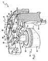
図1、2を参照すると、燃焼釘打ち機の全体が参照番号10に示されている。釘打ち機10は2005年10月3日に出願の米国特許出願第11/242,311号に詳細に記載されている。従来公知となっているように、工具主ハウジング12が燃焼室14および燃料セル室16を包囲している。燃料セルドア18がハウジング12に回動可能に取付けられており、工具の作動中に燃料セル室16を閉じるようになっている。こうしドアの構成は公知となっている。
Referring to FIGS. 1 and 2, the entire combustion nailing machine is shown at
本願と一体をなすものとして参照する米国特許第5,263,439に記載されているように、燃料セル室14内には燃料セル20が挿入される。該燃料セルの大まかな構成は、燃焼工具の分野では公知となっている。内部燃料計量弁22(図4、5)を有した本燃料セル20は、同時係属中の米国特許出願第10/827551号に記載されており、該出願を本願と一体をなすものとして参照する。概括的に、燃料弁のステム24は、バネ26によって閉弁位置に付勢されているが、軸方向に押圧されると、計量された一回量の燃料が供給される。軸方向に引っ張られると、ステム24は、その休止位置へ復帰し、次の燃焼サイクルのための一回量の燃料が計量室28内に流入する。
A
燃料セル20は、更に、外シェル30、該外シェルの上端に取付けられた閉蓋部32、スナップ式に嵌合するステム保護部34を主要な構成要素として含んでいる。前記閉蓋部に摩擦係合するステム保護部34は、ステム24の上端部を包囲し、かつ、該上端部を越えて延設された円筒スリーブ部36を含んでいる。スリーブ部36は、ステム24の損傷を防止したり、或いは、ステム24の望ましくない動作を防止して意図せず燃料が供給されることを防止する。
The
また、釘打ち機10には、燃料セル室16と協働する燃料セル作動装置38が設けられている。燃料セル作動装置は、燃料セルのステム24に軸方向の力を作用するように構成されている。この軸方向の力によって、計量された一回量の燃料が、各回の燃焼に先立って燃焼室14に供給される。作動装置38の1つの主要な構成要素は長尺の少なくとも1つの作動部材40である。該作動部材は、ステム24に軸方向の力を印加して一回量の燃料が放出されるようにする。本実施形態では、作動部材40はステム24に実際上接触している。
The nailing
概ね倒立U字形の溝42が作動部材40に形成されており、該溝内にステム受容ブロック44を含む燃料輸送装置が配設される。ステム受容ブロック44は、ピン(図示せず)によって溝42内に保持されている。前記ピンは、作動部材40およびステム受容ブロックの双方に形成された対応の穴内に挿通される。然しながら、ねじ締結や化学接着のような他の種類の固定方法を用いてもよい。ステム受容ブロック44は作動部材40の一端に配置されているが、他の位置であってもよい。ステム受容ブロック44からノズル48が垂下されスリーブ部36に係合している。該ノズルは、弁ステム24に積極的かつ気密に係合する寸法にて形成されている。本実施形態では、ノズル48は、弁ステム24に直接係合するようにスリーブ部36内に突出している。
A generally inverted
また、燃料輸送装置は、ステム受容ブロック44に形成された内部通路52を具備している。該内部通路は、作動部材40を溝42内に配置することによって、該作動部材と協働する燃料管路54に燃料セルの弁ステム24を連通させる。通路52は概ね直角に形成されており、概ね垂直に配向される燃料セル20およびステム24から供給される燃料を概ね水平方向にする。然しながら、通路52の形態は、用途に応じて変更することができよう。燃料管路54によって、燃料セルの弁ステム24がステム受容ブロック44および工具10のシリンダヘッド56に連通する。従来公知となっているように、シリンダヘッド56は燃焼室14を画成する構成要素の1つである。また、燃料管路54は、好ましくは柔軟なチューブである。該チューブは、その両端で、返しを設けた対応の継手45(図4)によって、シリンダヘッド56およびステム受容ブロック44の双方に接続されており、漏洩することなく燃料が燃焼室14へ輸送されるようになっている。用途に応じて、柔軟な或いは剛性の管路から成る他のタイプの接続装置を用いてもよい。
In addition, the fuel transport device includes an
作動部材40は、ステム受容ブロック44とは反対側の端部において、少なくとも1つのタブ、好ましくは2つのタブ58から成るピン連結部によって、シリンダヘッド56に回動自在に連結されている。タブ58は、シリンダヘッド56から延設され概ね平行に離間配置された耳部60に係合する。このように回動自在に連結することによって、作動装置38は、燃料セルを交換可能とする位置へ回動可能となる(図1)。
The actuating
また、作動装置38には、該作動装置へ軸方向の力を伝達して燃料セル20から計量された一回量の燃料を供給するための回動部材62が設けられている。上記力は、工具10の下端から延設されているワーク接触部材(図示せず)が後退することによって発生する。締結具駆動工具の分野では公知となっているように、締結具の駆動に先立って工具10がワークに押圧されると、ワーク接触部材が、該工具のワーク接触部材以外の要素に対して相対的に後退する。この後退動作は、弁スリーブによって燃焼室を閉じるといった、工具10の他の作用を機械的に生起させるために用いられる。本発明では、工具10に対するワーク接触部材の動作は、また、燃料セルステム24に軸方向の力を印加して燃料を供給するために用いられる。
The
より詳細には、ワーク接触部材は弁スリーブ64に機械的に連結されている。該弁スリーブは、少なくとも1つの好ましくは複数の鉛直に突出したラグ65(図2)を有している。該弁スリーブは、また、シリンダヘッド56に対して摺動自在に配設されている。工具10がワークに対して押圧されると、前記ワーク接触部材は、中間リンク機構(図示せず)を介してスリーブ64およびラグ65を鉛直方向に突出させる。この鉛直方向の動作によって、ラグ65が、上方から見て概ねU字形の動部材62の対応の腕部66に係合する。リンクロッド(図示せず)を用いて、この作用を奏するようにした燃焼工具も知られている。腕部66の対応の端部は、横木部分68において、好ましくは、ステム受容ブロック44の上側で作動部材40に連結されている。
More specifically, the workpiece contact member is mechanically connected to the
側方に延びるラグ70が、回動部材62から突出っし、燃料セルドア18に形成された対応のソケット部、つまり開口部72(図1)と回動自在に係合する。こうして、回動部材62は、燃料セルドア18の動作に合わせて、作動部材40と共に作動するよう移動し、また、該作動部材と共に作動しないよう移動する。図2において、工具10は燃焼完了後の休止位置にあり、ワーク接触部材およびピストンのような工具の構成要素は点火前位置に復帰している。作動装置38は、バネ26により弁ステム24に印加される内部バネ力によって、この位置に付勢されている。リンクロッド64は後退位置にて示されている。
A laterally extending
工具10がワークに対して押圧され、ワーク接触部材が工具に対して後退すると、リンクロッド64が上方に突出して回動部材62がラグ70を中心として回動する。これによって、横木部分68が作動部材40を軸方向に押下し、更に、ステム受容ブロック44の係合面がステム24に対して押圧される。この軸方向に押下げる力は、ステム24の付勢力に打勝ち、ステム受容ブロック44がスリーブ部36に対して係合することによって停止する。然しながら、ステム受容ブロックの下動動作によって、計量された一回量の燃料が放出、供給される。こうして、作動装置38は、第1の軸方向の力を受承し、そして作動部材40と協働してステムに軸方向に反対の力を発生するようになっている。燃焼サイクルの終点において、工具がワークから持上げられると、リンクロッド64が後退し、作動装置38は図2に示す休止位置に復帰する。
When the
次に、図3、4を参照すると、本発明による燃焼動力式締結具駆動工具または燃焼釘打ち機80が示されている。工具10と共通の構成要素には同じ参照番号が付されている。工具10と工具80との主要な差異は、ステム受容ブロック44がアクチュエータブロック82によって置換されている点である。該アクチュエータブロックは、ステム受容ブロックと同様に、燃料を燃料管路54へそして最終的に燃焼室14へ輸送する。アクチュエータブロック82の主要な特徴は、燃料セル20のアダプタが無い場合に、作動装置38によって主ステム24が作動してしまうことを防止するようになっている点である。特別に設計されたアダプタ84が、アクチュエータブロック82と共に使用されるように準備されるので、アダプタを備えない燃料セルは作動することがない。こうして、外部燃料計量弁を必要とする従来の燃料セルを工具80に不注意で装着しても、適正なアダプタが装着されない限り、工具が作動することはない。こうして、工具80に適正な一回量の燃料供給性が高められる。
3 and 4, a combustion powered fastener drive tool or
より詳細には、アクチュエータブロック82は、ステム受容ブロック44と多くの共通する構成要素を有するようにできるが、燃料セル20にアダプタが装着されていないときに、主ステム24に接触することなく、該主ステムを包囲する寸法にて形成されたステム空洞部86を有している。図4に示すように、ステム空洞部86は、概ね円錐状に形成されているが、ステム24を包囲し、かつ、アダプタ84が装着されていないときにステム24が作動しなければ、他の形状でもよい。空洞86は、休止位置(図4)にあるステム24を収容可能な高さと、ステムを作動させることなく回動部材62による動作を許容できる更なる隙間をステムの上方に有している。アクチュエータブロック82は、該ブロック82に着座する燃料セルの閉蓋部32に接触する先端部88を含んでいる。また、アクチュエータブロック82は、該ブロックをアダプタ84内に一層正確に位置決めするための半径方向に突出したフランジ部90を含んでいる。
More specifically, the actuator block 82 can have many common components with the stem receiving block 44, but without contacting the
図5〜7を参照して、アダプタ84を詳細に説明する。アダプタ84は、概ね円筒状に形成されたアダプタ本体92を主要部分として具備している。該アダプタ本体は、燃料セルの閉蓋部32によって形成された環状リング部94に嵌合する。リング部94に緊密に係合する環状溝98を有した少なくとも1つの保持部96によって、閉蓋部32に対するアダプタ84の緊密な摩擦嵌合が増強される。保持部96は、単一の閉じた環状に或いは離間配置された一連の突起部にて形成することができる。内部計量弁を備えていない燃料セルをユーザが誤って使用する可能性を低減するために、アダプタ84は、閉蓋部32から取外すことが非常に困難なように形成されている。更に、アダプタ84は、好ましくは、プラスチック材料から成形され、材料は、燃料耐性、成形性および耐久性はもとより剛性の観点から選択される。ノースカロライナ州シャーロット(Charlotte NC)所在のヘキストセラニーズ社(Hoechst Celanese)からセルコン(Celcon(R))の商標名で市販されているアセチルが好ましい材料として考えられるが、他のアセチル類、ポリアミド類或いは他の燃料耐性プラスチックでも適切なものがあろう。
The
アダプタ本体92の上方部分には、アクチュエータブロック82を受容するための開いた上端102を有し位置決めリング部100(図5)が形成されている。アダプタ82には、本体92によって内室104が画成されており、該内室には、アダプタ本体92に対して往復動自在のハブ106が配設されている。該ハブは、内腔112に連通したボア110を有した第1の端部108を有している。該第1の端部は、主ステム24に係合して該主ステムに連通する。ボア110は、内部計量弁を有した燃料セル20の主ステム24を緊密かつ摺動自在に受容する寸法を有している。更に、前記ボアは、内部計量弁を備えない燃料セルの主ステムと適正に嵌合しないような寸法にて形成されている。内腔112は、主ステム24に連通すると共に通路52に連通している。
A positioning ring portion 100 (FIG. 5) having an open
また、第1の端部には、環状の足部114が形成されており、該足部は、燃料セルの閉蓋部32に対する停止部として作用する。該停止部は、作動装置38の作用や或いはユーザによって生成された垂直方向の力による主ステム24の押下量を制限する上で重要である。主ステム24が過剰に押下されると、所定の一回量よりも多量の燃料が供給される。
An annular foot portion 114 is formed at the first end portion, and the foot portion acts as a stop portion for the
ハブ106において第1の端部108の反対側の第2の端部116は、アクチュエータブロック82に係合して該アクチュエータブロックと気密に連通する。好ましくは、ハブ106の第2の端部116およびステム空洞部86は、緊密に摩擦嵌合するように相補形状となっている。気密に嵌合することによって、ハブ106とブロック82の物理的な連結が容易になり、燃料漏洩を防止する気密関係が維持される。然しながら、ラグと凹み、環状のシールリップ、クラッシュリブその他着脱自在かつ気密にアクチュエータブロック82をハブに固定するたmねお固定、気密構造のような付加的な固定、気密構造を設けてもよい。
A
アダプタ84の1つの特徴は、ハブ106が本体に対して往復動動作して、ハブが主ステム24の繰り返し動作に追従可能となっている点である。こうして、ハブ106は、作動装置38および燃料セル20内のバネ26による動作に適合する。好ましい実施形態では、この往復動作は少なくとも1つの湾曲した可撓性部材118によってもたらされる。該可撓性部材は第1の端部でアダプタ本体92に固定され、反対側の第2の端部でハブ106に固定されている。可撓性部材118は、燃料セル20内に燃料弁ステム24を押下するのに必要な力に無視し得る力のみを付加するように設計されている。可撓性部材118は、螺旋状を呈し、かつ、概ね円形の断面を有しており、捩れ剛性を低減しながら柔軟性を高めるようになっている。
One feature of the
好ましくは、3つの可撓性部材118が配設されており、該可撓性部材によってハブ106は本体92に対して本質的に浮動支持されている。浮動支持作用に加えて、可撓性部材118は、前記ハブを図5に示す休止位置へ付勢している。作動装置38からの力を受けると、ハブ106は押下され、燃料ステム24もまたバネ26の付勢力に対抗して押下される。更に、可撓性部材118は、ハブ106と弁ステム24との間の製造上のばらつきを補償し、ステムに対してハブを適正に配置するのに十分な柔軟性を有している。
Preferably, three flexible members 118 are disposed such that the
図8を参照すると、アダプタ84の代替実施形態の全体が参照番号120にて指示されている。アダプタ84と共通する構成要素には同じ参照番号が付されている。基本的に、アダプタ120は、単一構成ではなく2体構成である点でアダプタ84と相違している。アダプタ120は、アダプタ本体122を具備している。アダプタ本体は、閉蓋の環状リング部94に係合し、同様にアダプタ本体92に摩擦嵌合する。然しながら、図示するように、保持構造は周方向に離間配置された複数の部分から成る。実質的に閉じられた室124が、本体122の上端部分に形成され、第2の要素としての往復動するハブ126が包囲される。ハブ126は、半径方向に突出したフランジ部128を具備質得る。該フランジ部は、室124内で往復摺動する寸法にて形成され、かつ、本体122の上蓋130によって前記室内に保持される。前記上蓋は、中心開口部132の部分を除いて前記室を閉鎖している。前記室内におけるハブ126の摺動性は、少なくとも弁ステム24の垂直方向の移動行程に対応している。フランジ部128の他の作用は足部114に類似しており、主ステム24の動作を制限している。従って、一度に一回量の燃料だけが供給される。
Referring to FIG. 8, an alternate embodiment of the
ハブ126は、下端に形成された弁ステム24を摺動自在に受容するボア110と、変形実施形態によるアクチュエータブロック134に形成された通路52に連通する内腔112とを含んでいる。ブロック134は、開口部132に嵌合、摺動自在で、かつ、フランジ部128の上面に接触できる寸法にて形成されたスリーブ部134を具備している。アダプタ84の場合と同様に、アダプタ120において、切頭円錐形の部分140を有したハブ126は、アクチュエータブロック134の相補形の凹部142に緊密、かつ、離脱可能に係合し、燃料セルの弁ステム24と通路52とが、漏洩なく気密に連通するようになっている。
The hub 126 includes a
本発明の燃料供給装置、特に燃料セル20から燃焼室14へ燃料を流通させるアクチュエータブロック82では、アダプタ84、120が配置されていなければならいことは理解されよう。そうでなければ、ハブ106、126は、単に燃料セルの閉蓋部32に係合するだけで、弁ステム24には係合しない。アダプタ84、120が無ければ、作動装置38は弁ステム24を作動させることはない。
It will be appreciated that the
本発明の燃焼工具の燃料セル用の改良された燃料通路を示し説明したが、特許請求の範囲に規定された本発明の範囲を逸脱することなく、その変更と修正が可能であることは当業者の当然とするところである。 Although an improved fuel passage for a fuel cell of a combustion tool of the present invention has been shown and described, it should be understood that changes and modifications can be made without departing from the scope of the present invention as defined in the claims. This is what a trader should take.
10 工具(釘打ち機)
12 ハウジング
14 燃料セル室
20 燃料セル
22 内部燃料計量弁
24 ステム
26 バネ
28 軽量室
30 外シェル
32 閉蓋部
34 ステム保護部
36 スリーブ部
38 燃料セル作動装置
40 作動部材
10 Tools (Nailer)
DESCRIPTION OF SYMBOLS 12 Housing 14
Claims (2)
燃料セルを受容するように構成された燃料セル室を画成する工具ハウジングを有した燃焼釘打ち機を具備し、
前記燃料セルは主ステムと、閉蓋部とを有しており、
前記燃焼釘打ち機と燃料セルとから成る組立体は、更に、
前記閉蓋部に摩擦係合するように形成されたアダプタであり、該アダプタと連結されたハブを有するアダプタと、
前記燃料セル室と協働し、工具の作動中に前記室内の燃料セルを作動させて、計量された一回量の燃料を放出させる燃料セル作動装置と、
前記作動装置と協働し、前記放出された一回量の燃料を受入れ、該燃料を燃焼室へ提供する燃料輸送装置とを具備し、
前記燃料輸送装置は、前記燃料セルにアダプタが装着されていないときに、前記作動装置による前記主ステムの作動を防止するように構成されている燃焼釘打ち機と燃料セルとから成る組立体。 In an assembly consisting of a combustion nailing machine and a fuel cell,
A combustion nailing machine having a tool housing defining a fuel cell chamber configured to receive a fuel cell;
The fuel cell has a main stem and a closing lid,
The assembly comprising the combustion nailing machine and the fuel cell further comprises:
A forming adapters to frictionally engage said closure portion, the adapter having a hub connected with the adapter,
A fuel cell operating device that cooperates with the fuel cell chamber to operate the fuel cell in the chamber during operation of the tool to release a metered dose of fuel;
A fuel transport device for cooperating with the actuating device for receiving the discharged single dose of fuel and providing the fuel to a combustion chamber;
The fuel transport device is an assembly comprising a combustion nailer and a fuel cell configured to prevent operation of the main stem by the operating device when an adapter is not attached to the fuel cell.
前記環状リング部に摩擦係合するように半径方向に突出した少なくとも1つの係合部を有したアダプタ本体と、
該アダプタ本体と連結され、かつ、前記本体に対して往復動自在に配設され、かつ、前記本体と共に動作して前記主ステムに係合可能に配設されたハブとを具備したアダプタ。 A fuel cell in a combustion nailer, the main stem and the fuel cell and a closure portion having an annular ring portion, and nailing with combustion transport device having an actuator blanking lock In the adapter used with the machine,
An adapter body having at least one engaging portion which projects radially so as to frictionally engage said annular ring portion,
An adapter including a hub connected to the adapter main body, reciprocally movable with respect to the main body, and operated with the main body to be engaged with the main stem.
Applications Claiming Priority (5)
| Application Number | Priority Date | Filing Date | Title |
|---|---|---|---|
| US81786406P | 2006-06-30 | 2006-06-30 | |
| US60/817,864 | 2006-06-30 | ||
| US11/810,238 US7478740B2 (en) | 2006-06-30 | 2007-06-05 | Enhanced fuel passageway and adapter for combustion tool fuel cell |
| US11/810,238 | 2007-06-05 | ||
| PCT/US2007/014729 WO2008005220A2 (en) | 2006-06-30 | 2007-06-26 | Enhanced fuel passageway and adapter for combustion tool fuel cell |
Publications (3)
| Publication Number | Publication Date |
|---|---|
| JP2009542447A JP2009542447A (en) | 2009-12-03 |
| JP2009542447A5 JP2009542447A5 (en) | 2010-08-12 |
| JP5363318B2 true JP5363318B2 (en) | 2013-12-11 |
Family
ID=38664742
Family Applications (1)
| Application Number | Title | Priority Date | Filing Date |
|---|---|---|---|
| JP2009518203A Expired - Fee Related JP5363318B2 (en) | 2006-06-30 | 2007-06-26 | Improved fuel passages and adapters for fuel passages in combustion tools |
Country Status (9)
| Country | Link |
|---|---|
| US (2) | US7478740B2 (en) |
| EP (1) | EP2051834B1 (en) |
| JP (1) | JP5363318B2 (en) |
| CN (1) | CN101489726B (en) |
| AU (1) | AU2007269876B2 (en) |
| CA (1) | CA2655751C (en) |
| NZ (1) | NZ574049A (en) |
| TW (1) | TWI468265B (en) |
| WO (1) | WO2008005220A2 (en) |
Families Citing this family (33)
| Publication number | Priority date | Publication date | Assignee | Title |
|---|---|---|---|---|
| JP5104536B2 (en) * | 2008-05-16 | 2012-12-19 | マックス株式会社 | Fuel filling container and gas combustion type driving tool |
| TW201016408A (en) * | 2008-10-22 | 2010-05-01 | Superior Power Tool Co Ltd | Gas filling structure of gas nailing gun |
| US7841499B2 (en) * | 2008-11-26 | 2010-11-30 | Superior Power Tool Co., Ltd. | Gas can mounting structure for gas-operated nail gun |
| US8042718B2 (en) * | 2009-09-03 | 2011-10-25 | Illinois Tool Works Inc. | Fuel cell actuation mechanism for combustion-powered tool |
| JP5555522B2 (en) * | 2010-03-29 | 2014-07-23 | 本田技研工業株式会社 | Handheld work machine |
| US9802303B2 (en) | 2010-04-13 | 2017-10-31 | Illinois Tool Works Inc. | Interface for fuel delivery system for combustion fastener driver |
| US8939339B2 (en) * | 2010-04-13 | 2015-01-27 | Illinois Tool Works Inc. | Interface for fuel delivery system for combustion nailer |
| US8302831B2 (en) * | 2010-04-13 | 2012-11-06 | Illinois Tool Works Inc. | Flanged fuel cell and locating structure for combustion tool |
| JP5648528B2 (en) * | 2011-02-22 | 2015-01-07 | マックス株式会社 | Gas fired driving tool |
| US8720764B2 (en) * | 2011-06-30 | 2014-05-13 | Illinois Tool Works Inc. | Fuel cell adapter |
| TWI451947B (en) | 2013-06-18 | 2014-09-11 | Basso Ind Corp | Gas guns for gas cylinders |
| NZ729330A (en) | 2014-03-03 | 2018-09-28 | Illinois Tool Works | Fuel cell adaptor for combustion fastener driver |
| US10759031B2 (en) | 2014-08-28 | 2020-09-01 | Power Tech Staple and Nail, Inc. | Support for elastomeric disc valve in combustion driven fastener hand tool |
| US9862083B2 (en) | 2014-08-28 | 2018-01-09 | Power Tech Staple and Nail, Inc. | Vacuum piston retention for a combustion driven fastener hand tool |
| DE202015003261U1 (en) | 2015-05-06 | 2015-06-01 | Olaf Kersten | Gas operated setting tool |
| TWI532571B (en) | 2015-10-12 | 2016-05-11 | Electric nail gun drive device | |
| TWM518150U (en) * | 2015-10-14 | 2016-03-01 | Basso Ind Corp | Gas nailer and fuel delivery device thereof |
| US10166666B2 (en) | 2015-11-25 | 2019-01-01 | Illinois Tool Works Inc. | Adapter for combustion tool fuel cells |
| US10668608B2 (en) | 2016-02-10 | 2020-06-02 | Illinois Tool Works Inc. | Fastener driving tool |
| USD812101S1 (en) | 2016-05-27 | 2018-03-06 | Illinois Tool Works Inc. | Combination fuel cell adapter and cap |
| US10598377B2 (en) * | 2016-05-27 | 2020-03-24 | Illinois Tool Works Inc. | Combustion-powered fastener driving tool fuel cell assembly |
| USD828398S1 (en) | 2016-12-08 | 2018-09-11 | Illinois Tool Works Inc. | Fuel cell metering valve |
| US10012993B1 (en) | 2016-12-09 | 2018-07-03 | Zendrive, Inc. | Method and system for risk modeling in autonomous vehicles |
| US10557738B2 (en) | 2017-09-11 | 2020-02-11 | Black & Decker Inc. | External fuel metering valve with shuttle mechanism |
| JP7093537B2 (en) * | 2017-10-16 | 2022-06-30 | 日本パワーファスニング株式会社 | Fuel container for gas-burning driving tools |
| USD854820S1 (en) | 2017-11-14 | 2019-07-30 | Illinois Tool Works Inc. | Fastener driving tool belt hook |
| USD855431S1 (en) | 2017-11-14 | 2019-08-06 | Illinois Tool Works Inc. | Fastener driving tool pipe hook |
| US10926391B2 (en) | 2017-11-14 | 2021-02-23 | Illinois Tool Works Inc. | Powered fastener driving tool having hook assemblies |
| US11624314B2 (en) | 2018-08-21 | 2023-04-11 | Power Tech Staple and Nail, Inc. | Combustion chamber valve and fuel system for driven fastener hand tool |
| US11426851B2 (en) * | 2019-08-21 | 2022-08-30 | Illinois Tool Works Inc. | Fastener driving tool |
| US11978915B2 (en) | 2020-09-01 | 2024-05-07 | Illinois Tool Works Inc. | Combustion-powered fastener driving tool fuel cell adapter |
| USD1001736S1 (en) | 2020-09-01 | 2023-10-17 | Illinois Tool Works Inc. | Fuel cell adapter for tool |
| US20230158651A1 (en) * | 2021-11-23 | 2023-05-25 | Illinois Tool Works Inc. | Fuel cell adapter for fastener driving tool |
Family Cites Families (24)
| Publication number | Priority date | Publication date | Assignee | Title |
|---|---|---|---|---|
| US4403722A (en) | 1981-01-22 | 1983-09-13 | Signode Corporation | Combustion gas powered fastener driving tool |
| US4483474A (en) | 1981-01-22 | 1984-11-20 | Signode Corporation | Combustion gas-powered fastener driving tool |
| IN157475B (en) | 1981-01-22 | 1986-04-05 | Signode Corp | |
| JPS62208380A (en) * | 1985-11-19 | 1987-09-12 | ジヨパド バデリ | Valve assembly and adapter used for valve assembly |
| JPS63248661A (en) * | 1987-03-31 | 1988-10-14 | ザ・ウエスト・カンパニ− | Applicator assembly used for liquid vessel |
| US5115944A (en) | 1990-08-14 | 1992-05-26 | Illinois Tool Works Inc. | Fluid dispenser having a collapsible inner bag |
| JP2606515Y2 (en) * | 1992-04-10 | 2000-11-27 | 株式会社ダイゾー | Container for fixed quantity injection aerosol |
| US5263439A (en) * | 1992-11-13 | 1993-11-23 | Illinois Tool Works Inc. | Fuel system for combustion-powered, fastener-driving tool |
| US5794831A (en) * | 1996-07-12 | 1998-08-18 | Illinois Tool Works Inc. | Fastener detection and firing control system for powered fastener driving tools |
| US6302297B1 (en) * | 2000-09-06 | 2001-10-16 | Illinois Tool Works Inc. | External metering valve for a fuel cell |
| US6523860B1 (en) * | 2000-10-12 | 2003-02-25 | Illinois Tool Works Inc. | Fuel cell adapter system for combustion tools |
| US6796478B2 (en) | 2000-10-12 | 2004-09-28 | Illinois Tool Works Inc. | Fuel cell adapter system for combustion tools |
| FR2833684B1 (en) * | 2001-12-18 | 2004-05-28 | Prospection & Inventions | COMPRESSED GAS CARTRIDGE FOR FIXING APPARATUS AND HATCH FOR ADAPTING AN INTERMEDIATE JOINT |
| US6786378B2 (en) * | 2002-01-09 | 2004-09-07 | Illinois Tool Works Inc. | Fastener tool having auxiliary fuel cell metering valve stem seal adaptor |
| DE10218194B4 (en) * | 2002-04-24 | 2004-05-13 | Hilti Ag | Setting tool that can be driven by expanding gases |
| US6938810B2 (en) * | 2003-04-15 | 2005-09-06 | Illinois Tool Works Inc. | Fuel cell adapter system for combustion tools |
| JP4239731B2 (en) * | 2003-07-04 | 2009-03-18 | マックス株式会社 | Contact mechanism of power driven nailer |
| JP2005046976A (en) * | 2003-07-31 | 2005-02-24 | Max Co Ltd | Firing control device of gas combustion type impact tool |
| JP4147403B2 (en) * | 2003-07-31 | 2008-09-10 | マックス株式会社 | Combustion chamber structure of gas-fired impact tool |
| US6964362B2 (en) * | 2004-02-06 | 2005-11-15 | Illinois Tool Works Inc. | Shock-absorbing system for fastener driving tools |
| JP4063233B2 (en) * | 2004-03-12 | 2008-03-19 | マックス株式会社 | Combustion gas nailer |
| US7392922B2 (en) | 2004-04-19 | 2008-07-01 | Illinois Tool Works Inc. | In-can fuel cell metering valve |
| US7314025B2 (en) * | 2005-07-15 | 2008-01-01 | Illinois Tool Works Inc. | Combustion powered fastener-driving tool with interconnected chambers |
| US7591249B2 (en) * | 2005-10-03 | 2009-09-22 | Illinois Tool Works Inc. | Actuation structure for internal fuel cell metering valve and associated combustion tool |
-
2007
- 2007-06-05 US US11/810,238 patent/US7478740B2/en active Active
- 2007-06-26 AU AU2007269876A patent/AU2007269876B2/en active Active
- 2007-06-26 WO PCT/US2007/014729 patent/WO2008005220A2/en active Application Filing
- 2007-06-26 EP EP07809873.8A patent/EP2051834B1/en active Active
- 2007-06-26 JP JP2009518203A patent/JP5363318B2/en not_active Expired - Fee Related
- 2007-06-26 CN CN2007800271139A patent/CN101489726B/en active Active
- 2007-06-26 NZ NZ574049A patent/NZ574049A/en unknown
- 2007-06-26 CA CA2655751A patent/CA2655751C/en active Active
- 2007-06-28 TW TW96123593A patent/TWI468265B/en active
-
2008
- 2008-09-04 US US12/204,530 patent/US7654429B2/en active Active
Also Published As
| Publication number | Publication date |
|---|---|
| NZ574049A (en) | 2011-12-22 |
| US7654429B2 (en) | 2010-02-02 |
| CA2655751C (en) | 2013-10-22 |
| EP2051834A2 (en) | 2009-04-29 |
| US20090001120A1 (en) | 2009-01-01 |
| EP2051834B1 (en) | 2020-03-11 |
| CA2655751A1 (en) | 2008-01-10 |
| US7478740B2 (en) | 2009-01-20 |
| AU2007269876A1 (en) | 2008-01-10 |
| TW200817146A (en) | 2008-04-16 |
| AU2007269876B2 (en) | 2013-09-26 |
| CN101489726A (en) | 2009-07-22 |
| WO2008005220A3 (en) | 2008-02-21 |
| CN101489726B (en) | 2011-08-03 |
| TWI468265B (en) | 2015-01-11 |
| JP2009542447A (en) | 2009-12-03 |
| US20080000451A1 (en) | 2008-01-03 |
| WO2008005220A2 (en) | 2008-01-10 |
Similar Documents
| Publication | Publication Date | Title |
|---|---|---|
| JP5363318B2 (en) | Improved fuel passages and adapters for fuel passages in combustion tools | |
| US8302831B2 (en) | Flanged fuel cell and locating structure for combustion tool | |
| JP4690393B2 (en) | Metering valve provided in the can fuel cell | |
| EP1957239B1 (en) | Actuation structure for internal fuel cell metering valve and associated combustion tool | |
| AU2012322690A1 (en) | Interface for fuel delivery system for combustion nailer |
Legal Events
| Date | Code | Title | Description |
|---|---|---|---|
| A521 | Written amendment |
Free format text: JAPANESE INTERMEDIATE CODE: A523 Effective date: 20100625 |
|
| A621 | Written request for application examination |
Free format text: JAPANESE INTERMEDIATE CODE: A621 Effective date: 20100625 |
|
| A131 | Notification of reasons for refusal |
Free format text: JAPANESE INTERMEDIATE CODE: A131 Effective date: 20121030 |
|
| A977 | Report on retrieval |
Free format text: JAPANESE INTERMEDIATE CODE: A971007 Effective date: 20121031 |
|
| A521 | Written amendment |
Free format text: JAPANESE INTERMEDIATE CODE: A523 Effective date: 20130125 |
|
| TRDD | Decision of grant or rejection written | ||
| A01 | Written decision to grant a patent or to grant a registration (utility model) |
Free format text: JAPANESE INTERMEDIATE CODE: A01 Effective date: 20130806 |
|
| A61 | First payment of annual fees (during grant procedure) |
Free format text: JAPANESE INTERMEDIATE CODE: A61 Effective date: 20130905 |
|
| R150 | Certificate of patent or registration of utility model |
Free format text: JAPANESE INTERMEDIATE CODE: R150 |
|
| R250 | Receipt of annual fees |
Free format text: JAPANESE INTERMEDIATE CODE: R250 |
|
| R250 | Receipt of annual fees |
Free format text: JAPANESE INTERMEDIATE CODE: R250 |
|
| LAPS | Cancellation because of no payment of annual fees |