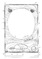
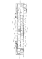
以下、パチンコ遊技機(以下、単に「パチンコ機」という)の一実施形態を、図面に基づいて詳細に説明する。ここで、図1はパチンコ機10の正面図であり、図2は斜視図であり、図3は内枠12及び前面枠セット14を開放した状態を示す斜視図である。図4は内枠12及び遊技盤30等の構成を示す正面図である。図5はパチンコ機10の背面図であり、図6は内枠12及び裏パックユニット203等を開放した状態を示す斜視図である。但し、図3では便宜上、遊技盤30面上に配設される釘や役物、前面枠セット14に取付けられるガラスユニット137等を省略して示している。
Hereinafter, an embodiment of a pachinko gaming machine (hereinafter simply referred to as “pachinko machine”) will be described in detail with reference to the drawings. Here, FIG. 1 is a front view of the pachinko machine 10, FIG. 2 is a perspective view, and FIG. 3 is a perspective view showing a state in which the inner frame 12 and the front frame set 14 are opened. FIG. 4 is a front view showing the configuration of the inner frame 12, the game board 30, and the like. FIG. 5 is a rear view of the pachinko machine 10, and FIG. 6 is a perspective view showing a state in which the inner frame 12, the back pack unit 203, and the like are opened. However, in FIG. 3, for the sake of convenience, nails and accessories placed on the surface of the game board 30, a glass unit 137 attached to the front frame set 14, and the like are omitted.
図3等に示すように、パチンコ機10は、当該パチンコ機10の外郭を構成する外枠11を備えており、この外枠11の一側部に内枠12が開閉可能に支持されている。
As shown in FIG. 3 and the like, the pachinko machine 10 includes an outer frame 11 that constitutes an outline of the pachinko machine 10, and an inner frame 12 is supported at one side of the outer frame 11 so as to be opened and closed. .
外枠11は、図6等に示すように、上辺枠構成部11a及び下辺枠構成部11bが木製の板材により構成され、左辺枠構成部11c及び右辺枠構成部11dがアルミニウム合金製の押出成形材により構成され、これら各枠構成部11a〜11dがネジ等の離脱可能な締結具により全体として矩形枠状に組み付けられている。
As shown in FIG. 6 and the like, the outer frame 11 has an upper side frame constituting portion 11a and a lower side frame constituting portion 11b made of a wooden plate material, and the left side frame constituting portion 11c and the right side frame constituting portion 11d are made of aluminum alloy. Each of the frame components 11a to 11d is assembled in a rectangular frame shape as a whole by a detachable fastener such as a screw.
左辺枠構成部11cの上下端部には、それぞれ上ヒンジ81及び下ヒンジ82が取着されている(図1参照)。当該上ヒンジ81及び下ヒンジ82にて、内枠12の上下部が回動可能に支持されており、これにより内枠12が開閉可能となる。そして、外枠11の内側に形成される空間部に内枠12等が収容される。
An upper hinge 81 and a lower hinge 82 are attached to the upper and lower ends of the left side frame constituting portion 11c (see FIG. 1). The upper and lower hinges 81 and 82 support the upper and lower portions of the inner frame 12 so that the inner frame 12 can be rotated. As a result, the inner frame 12 can be opened and closed. And the inner frame 12 etc. are accommodated in the space part formed inside the outer frame 11.
また、右辺枠構成部11dには、その幅方向後端部近傍から外枠11内側へ向け突出した延出壁部83が形成されている。延出壁部83は、内枠12の右側部背面側に設けられる施錠装置600(図6参照)に対応する上下区間全域を内枠12の背面側から覆っている(図5参照)。加えて、図3に示すように、延出壁部83の前面側には、施錠装置600の係止部材が係止される上下一対の受部84,85が設けられている。また、下側の受部85には、後述する内枠開放検知スイッチ92に当接する押圧部86が、外枠11内側に向けて突設されている。
The right side frame constituting portion 11d is formed with an extending wall portion 83 that protrudes from the vicinity of the rear end portion in the width direction toward the inside of the outer frame 11. The extending wall 83 covers the entire upper and lower sections corresponding to the locking device 600 (see FIG. 6) provided on the back side of the right side of the inner frame 12 from the back side of the inner frame 12 (see FIG. 5). In addition, as shown in FIG. 3, a pair of upper and lower receiving portions 84 and 85 to which the locking member of the locking device 600 is locked are provided on the front surface side of the extending wall portion 83. Further, a pressing portion 86 that abuts on an inner frame opening detection switch 92 described later is provided on the lower receiving portion 85 so as to protrude toward the inner side of the outer frame 11.
さらに、下辺枠構成部11bには樹脂製の幕板飾り87が取着されている。幕板飾り87の上面奥部には、上方に突出するリブ88が一体形成されている。これにより内枠12との間に隙間が形成されにくくなっている。
Furthermore, a resin curtain decoration 87 is attached to the lower frame constituting portion 11b. A rib 88 projecting upward is integrally formed at the back of the upper surface of the curtain decoration 87. This makes it difficult to form a gap with the inner frame 12.
図3に示すように、内枠12の開閉軸線は、パチンコ機10の正面からみて左側において上下に沿って設定されており、この開閉軸線を軸心として内枠12が前方側に開放できるようになっている。内枠12は、外形が矩形状をなす樹脂ベース38を主体に構成されており、当該樹脂ベース38の中央部には略楕円形状の窓孔39が形成されている。
As shown in FIG. 3, the opening / closing axis of the inner frame 12 is set up and down on the left side when viewed from the front of the pachinko machine 10, so that the inner frame 12 can be opened forward with the opening / closing axis serving as an axis. It has become. The inner frame 12 is mainly composed of a resin base 38 whose outer shape is rectangular, and a substantially elliptical window hole 39 is formed at the center of the resin base 38.
また、内枠12の前面側には前面枠セット14が開閉可能に取付けられている。前面枠セット14は、内枠12と同様に、パチンコ機10の正面から見て左側において上下に沿って設定された開閉軸線を軸心として前方側に開放できるようになっている。
A front frame set 14 is attached to the front side of the inner frame 12 so that it can be opened and closed. As with the inner frame 12, the front frame set 14 can be opened forward with an opening / closing axis set along the top and bottom on the left side when viewed from the front of the pachinko machine 10.
前面枠セット14は、内枠12と同様に外形が矩形状をなし、閉鎖状態においては内枠12の前面側ほぼ全域を覆う。前面枠セット14の中央部には略楕円形状の窓部101が形成されている。これにより、前面枠セット14の窓部101及び内枠12の窓孔39を介して、内枠12の後面に装着される遊技盤30(遊技領域)を外部から視認可能となる。遊技盤30の詳細な構成については後述する。
The front frame set 14 has a rectangular outer shape like the inner frame 12, and covers almost the entire front side of the inner frame 12 in the closed state. A substantially elliptical window 101 is formed at the center of the front frame set 14. Thereby, the game board 30 (game area) attached to the rear surface of the inner frame 12 can be visually recognized from the outside through the window portion 101 of the front frame set 14 and the window hole 39 of the inner frame 12. The detailed configuration of the game board 30 will be described later.
図1に示すように、前面枠セット14の前面側には、その下部中央において球受皿としての下皿15が設けられており、排出口16より排出された遊技球Bが下皿15内に貯留可能になっている。また、下皿15の手前側には、下皿15内から遊技球Bを排出するための球抜きレバー25が設けられている。加えて、下皿15の左部には、LEDが内蔵された演出ボタン125が設けられており、演出ボタン125を押圧操作することで、後述する装飾図柄表示装置42等において対応する演出が行われたり、演出内容が変更されたりする。
As shown in FIG. 1, a lower tray 15 serving as a ball tray is provided at the lower center of the front side of the front frame set 14, and the game ball B discharged from the discharge port 16 is placed in the lower tray 15. It can be stored. Further, a ball removal lever 25 for discharging the game ball B from the lower plate 15 is provided on the front side of the lower plate 15. In addition, an effect button 125 with a built-in LED is provided on the left side of the lower plate 15, and by pressing the effect button 125, a corresponding effect is performed on a decorative symbol display device 42 described later. Or the production content is changed.
下皿15の右方には、手前側に突出した遊技球発射ハンドル(以下、単にハンドルという)18が設けられている。尚、ハンドル18には、図示しないタッチセンサや、ハンドル18の操作部の操作量を検出するための図示しない操作量検出手段が設けられている。
On the right side of the lower plate 15, a game ball launching handle (hereinafter simply referred to as a handle) 18 protruding toward the front side is provided. The handle 18 is provided with a touch sensor (not shown) and an operation amount detection means (not shown) for detecting the operation amount of the operation unit of the handle 18.
下皿15の上方には上皿19が設けられている。上皿19は、遊技球Bを一旦貯留し、一列に整列させながら後述する発射手段としての遊技球発射装置(以下、単に発射装置という)60の方へ案内する球受皿である。尚、上皿19が遊技球Bで満杯になった状態では、払出される遊技球Bは、後述する下皿連通路71及び排出口16を介して、下皿15へと案内される。
An upper plate 19 is provided above the lower plate 15. The upper plate 19 is a ball tray that temporarily stores the game balls B and guides them toward a game ball launching device (hereinafter simply referred to as launching device) 60 as launching means, which will be described later, while being aligned in a row. When the upper plate 19 is full of the game balls B, the game balls B to be paid out are guided to the lower plate 15 through the lower plate communication path 71 and the discharge port 16 described later.
上皿19には球貸しボタン121と返却ボタン122とが設けられている。これにより、遊技ホール等において、パチンコ機10の側方に配置されるカードユニット(球貸しユニット)に紙幣やカード等を投入した状態で球貸しボタン121が操作されると、その操作に応じて貸出球が上皿19に供給される。一方、返却ボタン122は、カードユニットに挿入されたカード等の返却を求める際に操作される。但し、カードユニットを介さずに球貸し装置等から上皿19に遊技球Bが直接貸し出されるパチンコ機、いわゆる現金機では球貸しボタン121及び返却ボタン122は不要である。
The upper plate 19 is provided with a ball lending button 121 and a return button 122. Thereby, in the game hall or the like, when the ball lending button 121 is operated with a bill or a card inserted into a card unit (ball lending unit) arranged on the side of the pachinko machine 10, depending on the operation Rental balls are supplied to the upper plate 19. On the other hand, the return button 122 is operated when requesting the return of a card or the like inserted into the card unit. However, the ball lending button 121 and the return button 122 are not necessary for a pachinko machine in which the game ball B is directly rented to the upper plate 19 from a ball lending device or the like without using a card unit, so-called cash machine.
さらに、上皿19には、球抜きボタン123が設けられている。球抜きボタン123が押圧操作されることで、上皿19の球案内路の下流側に設けられ、下皿15に連通する連通孔(図示略)が開口し、上皿19に貯留されていた遊技球Bが下皿15へと案内される(落下する)。つまり、遊技者は、球抜きボタン123を操作することで、上皿19にある遊技球Bをいつでも下皿15に移すことができる。
Further, the upper plate 19 is provided with a ball removal button 123. When the ball removal button 123 is pressed, a communication hole (not shown) provided on the downstream side of the ball guide path of the upper plate 19 and communicating with the lower plate 15 is opened and stored in the upper plate 19. The game ball B is guided (dropped) to the lower plate 15. That is, the player can move the game ball B on the upper plate 19 to the lower plate 15 at any time by operating the ball removal button 123.
また、前面枠セット14の前面にはその周囲に各種ランプ等の発光手段が設けられている。これら発光手段は、大当たり時や所定のリーチ時等における遊技状態の変化に応じて点灯、点滅といった発光態様が変更制御され遊技中の演出効果を高める役割を果たすものである。例えば、窓部101の周縁には、LED等の発光手段を内蔵した枠ランプ102が設けられている。また、該枠ランプ102の両側部には、所定のエラー時に点灯するエラー表示ランプ104が設けられている。尚、枠ランプ102のうち各エラー表示ランプ104の上方部位には、前面枠セット14の背面に設けられるスピーカSP(図3参照)に対応して細かな透孔が多数形成されている。
In addition, light emitting means such as various lamps are provided around the front surface of the front frame set 14. These light emitting means play a role of enhancing the effect of the game during the game by changing and controlling the light emission mode such as lighting and blinking according to the change of the game state at the time of big hit or predetermined reach. For example, a frame lamp 102 incorporating a light emitting means such as an LED is provided on the periphery of the window 101. Further, on both sides of the frame lamp 102, there are provided error display lamps 104 that are turned on when a predetermined error occurs. Note that a number of fine through holes corresponding to the speaker SP (see FIG. 3) provided on the back surface of the front frame set 14 are formed in the frame lamp 102 above the error display lamps 104.
前面枠セット14の背面側にはガラスユニット137が取付けられている。ガラスユニット137は、従来の前後一対の矩形状の板ガラスが前後対をなして別々に取着されるものではなく、全体として丸形をなし、アッセンブリ化された上で取付けられている。
A glass unit 137 is attached to the back side of the front frame set 14. The glass unit 137 is not attached to a pair of conventional front and rear rectangular glass plates separately in front and rear pairs, but is formed into a round shape as a whole and attached after being assembled.
次に、内枠12(樹脂ベース38)について図4を参照して説明する。上述した通り、内枠12(樹脂ベース38)には、窓孔39の後側において遊技盤30が装着されている。遊技盤30は、その周縁部が内枠12(樹脂ベース38)の裏側に当接した状態で取着されている。従って、遊技盤30の前面部の略中央部分が樹脂ベース38の窓孔39を通じて内枠12の前面側に露出した状態となっている。
Next, the inner frame 12 (resin base 38) will be described with reference to FIG. As described above, the game board 30 is mounted on the inner frame 12 (resin base 38) on the rear side of the window hole 39. The game board 30 is attached in a state in which the peripheral edge thereof is in contact with the back side of the inner frame 12 (resin base 38). Therefore, a substantially central portion of the front surface portion of the game board 30 is exposed to the front surface side of the inner frame 12 through the window hole 39 of the resin base 38.
また、内枠12(樹脂ベース38)の前面下部、すなわち窓孔39(遊技盤30)の下方位置には、発射装置60及び当該発射装置60より発射された直後の遊技球Bを案内する発射レール61が取付けられている。本実施形態では、発射装置60としてソレノイド式発射装置を採用している。また、発射装置60の上方には、上皿19から案内される遊技球Bを、内蔵された駆動手段(例えばソレノイド)の駆動により、1球ずつ発射装置60の発射位置へと案内する球送り装置63が設けられている。
In addition, in the lower part of the front surface of the inner frame 12 (resin base 38), that is, in the lower position of the window hole 39 (game board 30), the launching device 60 and launching that guides the game ball B immediately after being launched from the launching device 60. A rail 61 is attached. In the present embodiment, a solenoid-type firing device is employed as the firing device 60. Further, above the launching device 60, a ball feed for guiding the game ball B guided from the upper plate 19 to the launching position of the launching device 60 one by one by driving a built-in driving means (for example, solenoid). A device 63 is provided.
次に、遊技盤30の構成について図4を参照して説明する。遊技盤30には、一般入賞口31、可変入賞装置32、始動入賞ユニット(始動口)33、スルーゲート34、可変表示装置ユニット35、第1特別表示装置43L及び第2特別表示装置43R等がルータ加工によって形成された貫通孔に配設され、遊技盤30前面側から木ネジ等により取付けられている。周知の通り一般入賞口31、可変入賞装置32、始動入賞ユニット33などの各種入賞口に遊技球Bが入球(入賞)すると、各種検出スイッチにより検出され、上皿19(又は下皿15)へ所定数の賞球が払い出される。例えば、始動入賞ユニット33への入球があった場合には3個、一般入賞口31への入球があった場合には10個、可変入賞装置32への入球があった場合には15個の遊技球Bが上皿19(下皿15)に払出される。その他に、遊技盤30にはアウト口36が設けられており、一般入賞口31等の各種入賞口に入賞しなかった遊技球Bは、このアウト口36を通って遊技領域外へと排出される。また、遊技盤30には、遊技球Bの落下方向を適宜分散、調整等するために多数の釘が植設されているとともに、風車等の各種部材(役物)が配設されている。
Next, the configuration of the game board 30 will be described with reference to FIG. The game board 30 includes a general winning port 31, a variable winning device 32, a starting winning unit (starting port) 33, a through gate 34, a variable display device unit 35, a first special display device 43L, a second special display device 43R, and the like. It is disposed in a through hole formed by router processing, and is attached from the front side of the game board 30 with a wood screw or the like. As is well known, when the game ball B enters (wins) various winning holes such as the general winning opening 31, the variable winning device 32, the start winning unit 33, etc., it is detected by various detection switches, and the upper plate 19 (or the lower plate 15). A predetermined number of prize balls are paid out. For example, when there is a ball entering the start winning unit 33, there are three balls when there is a ball entering the general winning slot 31, and when there is a ball entering the variable winning device 32. Fifteen game balls B are paid out to the upper plate 19 (lower plate 15). In addition, the game board 30 is provided with an out port 36, and the game balls B that have not won the various winning ports such as the general winning port 31 are discharged out of the game area through the out port 36. The Further, the game board 30 is provided with a large number of nails for distributing and adjusting the falling direction of the game ball B as appropriate, and various members (acts) such as a windmill.
始動入賞ユニット33は、所定の入球手段(始動入球手段)としての上入賞口33a(第1始動入球手段)及び下入賞口33b(第2始動入球手段)と、下入賞口33bの両側部に設けられた開閉する一対の開閉部材33cを備えている。上入賞口33aは、遊技球Bが常時入球可能となっているのに対し、下入賞口33bは、開閉部材33cが所定条件の成立に応じて開閉動作することにより、遊技領域を流下する遊技球Bが入球可能な開状態と、遊技球Bが入球不可能な閉状態との間で状態変化可能に構成されている。尚、詳しくは後述するが、始動入賞ユニット33は、上入賞口33a、下入賞口33bに入球した遊技球Bをそれぞれ検知する条件成立検出手段(入球検知手段)としての第1始動入賞スイッチ224a、第2始動入賞スイッチ224bを備えており、当該始動入賞スイッチ224a、224bにて遊技球Bが検知された場合に、大当たり状態を発生させるか否かの当否抽選が行われるとともに、特別表示装置43L、43R(及び後述する装飾図柄表示装置42)にて変動表示が行われる構成となっている。そして、当否抽選にて当選した場合には、大当たり状態(特別遊技状態)が付与される。
The start winning unit 33 includes an upper winning opening 33a (first starting entering means) and a lower winning opening 33b (second starting entering means) as predetermined entering means (start entering means), and a lower winning opening 33b. A pair of opening / closing members 33c provided on both sides of the opening / closing member is provided. The upper winning opening 33a allows the game ball B to always enter, while the lower winning opening 33b flows down the game area by the opening / closing member 33c opening and closing in accordance with the establishment of a predetermined condition. A state change is possible between an open state in which the game ball B can enter and a closed state in which the game ball B cannot enter. As will be described in detail later, the start winning unit 33 is a first start winning as a condition establishment detection means (entrance detection means) that detects the game balls B that have entered the upper winning opening 33a and the lower winning opening 33b. A switch 224a and a second start winning switch 224b. When the game ball B is detected by the start winning switches 224a and 224b, whether or not to generate a big hit state is determined, and a special lottery is performed. The display devices 43L and 43R (and a decorative symbol display device 42 to be described later) are configured to perform variable display. And, when winning in the winning / losing lottery, a big win state (special game state) is given.
本実施形態では、大当たり種別として、「16R確変大当たり」、「16R通常大当たり」、「2R確変大当たり」及び「2R潜伏確変大当たり」がある。「16R確変大当たり」及び「16R通常大当たり」の大当たり状態においては、可変入賞装置32が30秒間開放状態とされる、又は可変入賞装置32に8個の遊技球Bが入賞することを1ラウンドとして、これが16回繰り返される。一方、「2R確変大当たり」及び「2R潜伏確変大当たり」の大当たり状態においては、可変入賞装置32が0.4秒間開放状態とされることを1ラウンドとして、これが2回繰り返される。すなわち、「16R確変大当たり」及び「16R通常大当たり」の大当たり状態は、遊技球Bの大幅な増加が望めるのであるが、「2R確変大当たり」及び「2R潜伏確変大当たり」の大当たり状態は、大当たり状態中に獲得可能な遊技球Bの数が著しく少ない(遊技球Bの増加がほぼ望めない)ものとなる。
In the present embodiment, the jackpot types include “16R probability variation jackpot”, “16R normal variation jackpot”, “2R probability variation jackpot”, and “2R latent probability variation jackpot”. In the jackpot states of “16R probability variable jackpot” and “16R normal jackpot”, the variable winning device 32 is kept open for 30 seconds, or eight game balls B win the variable winning device 32 as one round. This is repeated 16 times. On the other hand, in the jackpot states of “2R probability variation jackpot” and “2R latent probability variation jackpot”, the variable winning device 32 is opened for 0.4 seconds, and this is repeated twice. In other words, the big hit state of “16R probability variation jackpot” and “16R normal jackpot” can expect a large increase in game ball B, but the big hit state of “2R probability variation jackpot” and “2R latent probability variation jackpot” The number of game balls B that can be acquired is remarkably small (the increase of the game balls B can hardly be expected).
さらに、「16R確変大当たり」、「2R確変大当たり」又は「2R潜伏確変大当たり」が発生した場合には、大当たり状態の終了後に高確率状態(特定モードとしての高確率モード)が付与される。但し、「2R潜伏確変大当たり」が発生した場合には、高確率モードが付与されている状態を遊技者が認識しにくい状態、すなわち潜伏状態(潜伏確変モード)となる。一方、「16R通常大当たり」が発生した場合、大当たり状態の終了後に低確率状態(時間短縮モードや通常モード等の低確率モード)が付与される。
Further, when “16R probability variation jackpot”, “2R probability variation jackpot”, or “2R latent probability variation jackpot” occurs, a high probability state (high probability mode as a specific mode) is given after the jackpot state ends. However, when “2R latent probability variation jackpot” occurs, the player is in a state where it is difficult for the player to recognize the state in which the high probability mode is given, that is, the latent state (latency probability variation mode). On the other hand, when “16R normal jackpot” occurs, a low probability state (low probability mode such as a time reduction mode or a normal mode) is given after the jackpot state ends.
尚、本実施形態では、遊技球Bが上入賞口33aに入球した場合と、下入賞口33bに入賞した場合とで、当否抽選にて当選した場合に付与される大当たり種別の振分けが異なるようになっている。上入賞口33aへの遊技球Bの入球を契機とする当否抽選に当選した場合には、「16R確変大当たり」、「16R通常大当たり」、「2R確変大当たり」又は「2R潜伏確変大当たり」のいずれかに振分けられ、下入賞口33bへの遊技球Bの入球を契機とする当否抽選に当選した場合には、「16R確変大当たり」又は「16R通常大当たり」のどちらかに振分けられることとなる。
In the present embodiment, the distribution of the jackpot type that is given when the game ball B enters the top winning opening 33a and when the game ball B wins the bottom winning opening 33b is different in the winning lottery. It is like that. If the winning lottery with the game ball B entering the top winning hole 33a is won, “16R probability variation jackpot”, “16R normal variation jackpot”, “2R probability variation jackpot” or “2R latent probability variation jackpot” If the winning ballot is triggered by the game ball B entering the lower prize opening 33b, it will be assigned to either “16R probable big hit” or “16R normal jackpot” Become.
第1及び第2特別表示装置43L、43Rは、7セグメント表示装置により構成され、可変入賞装置32の右方に設置されている。そして、始動入賞ユニット33の上入賞口33aへの遊技球Bの入球を契機として第1特別表示装置43Lにて切替表示(変動表示)が行われ、下入賞口33bへの遊技球Bの入球を契機として第2特別表示装置43Rにて切替表示(変動表示)が行われる構成となっている。尚、特別表示装置43L、43Rは、後述する主制御装置261によって表示内容が直接的に制御される。
The first and second special display devices 43 </ b> L and 43 </ b> R are configured by 7-segment display devices and are installed on the right side of the variable winning device 32. Then, when the game ball B enters the top winning port 33a of the start winning unit 33, a switching display (variable display) is performed on the first special display device 43L, and the game ball B is input to the lower winning port 33b. The switch display (fluctuation display) is performed on the second special display device 43 </ b> R when the ball is entered. The display contents of the special display devices 43L and 43R are directly controlled by a main control device 261 described later.
また、第1及び第2特別表示装置43L、43Rにて変動表示が行われた後、当該変動表示が停止したときの表示態様(例えば、文字)により、大当たりか否かが確定的に表示される。例えば、上入賞口33aに遊技球Bが入賞すると、対応する第1特別表示装置43Lにて、「−」→「7」→「3」→「2」→「1」→「−」→・・・という具合に高速で(例えば4msec毎に)切替表示(変動表示)がなされ、所定時間が経過すると、いずれかの表示態様を停止表示(例えば数秒間停止)する。そして、大当たり抽選に当選した場合には、「7」、「3」、「2」、「1」のいずれかが変動停止時に表示され、大当たり状態が発生する。但し、遊技球Bが下入賞口33bへ入賞した場合には、「2R確変大当たり」及び「2R潜伏確変大当たり」は発生しないため、第2特別表示装置43Rにおいて「2」、「1」が決定表示されることはない。
In addition, after the variable display is performed on the first and second special display devices 43L and 43R, whether or not a big hit is determined is displayed depending on the display mode (for example, characters) when the variable display is stopped. The For example, when the game ball B wins the top winning opening 33a, “-” → “7” → “3” → “2” → “1” → “−” → • on the corresponding first special display device 43L. ... Is displayed at high speed (for example, every 4 msec), and when a predetermined time has elapsed, one of the display modes is stopped (for example, stopped for a few seconds). Then, when the big hit lottery is won, any one of “7”, “3”, “2”, and “1” is displayed when the fluctuation is stopped, and a big win state is generated. However, when the game ball B wins the lower winning opening 33b, the “2R probability variation jackpot” and the “2R latent probability variation jackpot” do not occur, so “2” and “1” are determined in the second special display device 43R. It is never displayed.
具体的に、「16R確変大当たり」が付与される場合には、第1又は第2特別表示装置43L、43Rにおいて「7」が停止表示され、「16R通常大当たり」が付与される場合には、第1又は第2特別表示装置43L、43Rにおいて「3」が停止表示され、「2R確変大当たり」が付与される場合には第1特別表示装置43Lにおいて「2」が停止表示され、「2R潜伏確変大当たり」が付与される場合には第1特別表示装置43Lにおいて「1」が停止表示される。
Specifically, when “16R probability big hit” is given, “7” is stopped and displayed on the first or second special display device 43L, 43R, and when “16R normal big hit” is given, When “3” is stopped and displayed on the first or second special display device 43L, 43R, and “2R probability variation big hit” is given, “2” is stopped and displayed on the first special display device 43L, and “2R latency” When “probable big hit” is given, “1” is stopped and displayed on the first special display device 43L.
また、第1特別表示装置43L又は第2特別表示装置43Rのどちらか一方において、変動表示又は決定表示が行われている場合には、他方が消灯状態とされており(「−」を表示しておいてもよい)、どちらにおいても変動表示及び決定表示が行われていない場合には、両方においてそれぞれ「−」が表示される。
In addition, when either the first special display device 43L or the second special display device 43R is performing variable display or determination display, the other is turned off ("-" is displayed). However, if neither the change display nor the determination display is performed in either case, “-” is displayed in both cases.
また、第1又は第2特別表示装置43L、43Rの変動表示中に新たに遊技球Bが始動入賞ユニット33に入賞した場合には、その分の変動表示は、その時点で行われている変動表示の終了後に行われる構成となっている。つまり、変動表示が待機(保留)されることとなる。この保留される変動表示の最大回数は、パチンコ機の機種毎に決められているが、本実施形態では、上入賞口33aに入賞した遊技球B、及び下入賞口33bに入賞した遊技球Bに対応して、それぞれ4回までの変動表示(合計8回の変動表示)が保留される。また、その保留回数が第1保留ランプ46a、第2保留ランプ46bにて点灯表示されるようになっている。尚、大当たり状態中に新たに遊技球Bが始動入賞ユニット33に入賞した場合、その分の変動表示についても保留される。
Further, when the game ball B newly wins the start winning unit 33 during the fluctuation display of the first or second special display device 43L, 43R, the fluctuation display for that time is the fluctuation being performed at that time. The configuration is performed after the display is completed. That is, the variable display is on standby (held). The maximum number of the variable display to be held is determined for each model of the pachinko machine, but in this embodiment, the game ball B that wins the top winning port 33a and the game ball B that wins the bottom winning port 33b. Corresponding to the above, up to 4 times of variation display (total 8 times of variation display) is put on hold. In addition, the number of times of holding is lit and displayed by the first holding lamp 46a and the second holding lamp 46b. In addition, when the game ball B newly wins the start winning unit 33 during the big hit state, the fluctuation display for that amount is also put on hold.
尚、基本的に、上入賞口33aへの入賞を契機とする変動表示は、対応する遊技球Bが上入賞口33aへ入球した順に記憶されるとともに入球した順に消化され、下入賞口33bへの入賞を契機とする変動表示は、対応する遊技球Bが下入賞口33bへ入球した順に記憶されるとともに入球した順に消化される。但し、上入賞口33aへの入賞を契機とする変動表示、及び、下入賞口33bへの入球を契機とする変動表示の両方が保留されている場合(第1保留ランプ46a及び第2保留ランプ46bがそれぞれ1つ以上点灯している場合)には、下入賞口33bへの入球を契機とする変動表示が優先的に消化される。すなわち、下入賞口33bへの入賞を契機とする変動表示が全て消化された状態でなければ、上入賞口33aへの入球を契機とする変動表示が行われない構成となっている。例えば、第1保留ランプ46aが1つ点灯している状態において、下入賞口33bに遊技球Bが入球し、第2保留ランプ46bが1つ点灯した場合、上入賞口33aへの入球を契機とする変動表示が後回しにされ、先に下入賞口33bへの入球を契機とする変動表示が行われることとなる。
Basically, the variable display triggered by winning at the top winning opening 33a is stored in the order in which the corresponding game balls B have entered the top winning opening 33a and digested in the order in which they have entered the bottom winning opening. The change display triggered by winning a prize to 33b is stored in the order in which the corresponding game balls B have entered the lower winning opening 33b and are digested in the order in which they entered. However, when both the variable display triggered by winning in the upper winning opening 33a and the variable display triggered by entering the lower winning opening 33b are held (the first holding lamp 46a and the second holding hold) In the case where one or more lamps 46b are lit), the variable display triggered by the entry into the lower prize opening 33b is preferentially digested. In other words, unless all the variable displays triggered by winning in the lower winning opening 33b are digested, the variable display triggered by entering the upper winning opening 33a is not performed. For example, in the state where one first holding lamp 46a is lit, when a game ball B enters the lower winning opening 33b and one second holding lamp 46b lights, the entering into the upper winning opening 33a As a trigger, the variable display is postponed, and the variable display is triggered in advance by entering the lower winning award 33b.
また、スルーゲート34は、遊技領域を流下する遊技球Bが1球ずつ通過可能に構成されている。詳しくは後述するが、スルーゲート34は、当該スルーゲート34を通過する遊技球Bを検知可能なスルーゲートスイッチ225を備えており、当該スルーゲートスイッチ225にて遊技球Bが検知された場合に、始動入賞ユニット33を開状態とするか否かの開放抽選が行われるとともに、普通図柄表示装置41にて変動表示が行われる構成となっている。そして、開放抽選にて当選した場合には、始動入賞ユニット33(開閉部材33c)が規定時間だけ開状態とされる。
Further, the through gate 34 is configured so that the game balls B flowing down the game area can pass one by one. As will be described in detail later, the through gate 34 includes a through gate switch 225 that can detect the game ball B passing through the through gate 34, and when the game ball B is detected by the through gate switch 225. An open lottery for determining whether or not the start winning unit 33 is in an open state is performed, and a variable display is performed on the normal symbol display device 41. When the winning lottery is won, the start winning unit 33 (opening / closing member 33c) is opened for a specified time.
可変表示装置ユニット35には、スルーゲート34の通過を契機として変動表示する普通図柄表示装置41と、第1及び第2特別表示装置43L、43Rによる変動表示に合わせて変動表示する装飾図柄表示装置42とが設けられている。さらに、可変表示装置ユニット35には、装飾図柄表示装置42にて行われている変動表示が上入賞口33a及び下入賞口33bのうちどちらの入球に対応するものであるかを示す変動特定ランプ40と、上記第1保留ランプ46a及び第2保留ランプ46bと、保留ランプ44とが設けられている。
The variable display device unit 35 includes a normal symbol display device 41 that variably displays triggered by the passage of the through gate 34, and a decorative symbol display device that variably displays in accordance with the variable display by the first and second special display devices 43L and 43R. 42 is provided. Further, the variable display device unit 35 indicates a variation indicating whether the variation display performed on the decorative symbol display device 42 corresponds to which of the top winning opening 33a and the lower winning opening 33b. A lamp 40, the first holding lamp 46a and the second holding lamp 46b, and a holding lamp 44 are provided.
普通図柄表示装置41は、普通図柄として「○」又は「×」を点灯表示可能に構成されており、遊技球Bがスルーゲート34を通過する毎に例えば普通図柄を「○」→「×」→「○」→・・・という具合に高速で切換表示(変動表示)する。そして、その変動表示が「○」図柄(当選図柄)で数秒間停止した場合には、始動入賞ユニット33が所定時間だけ開状態となる。この普通図柄表示装置41は、後述する主制御装置261によって直接的に表示内容が制御される。
The normal symbol display device 41 is configured so that “O” or “X” can be turned on as a normal symbol, and each time the game ball B passes through the through gate 34, for example, the normal symbol is changed from “O” to “X”. → "○" → ... and so on, display the display at a high speed (change display). Then, when the change display is stopped for several seconds with the “◯” symbol (winning symbol), the start winning unit 33 is opened for a predetermined time. The display contents of the normal symbol display device 41 are directly controlled by a main control device 261 described later.
また、普通図柄表示装置41の変動表示中に、新たに遊技球Bがスルーゲート34を通過した場合には、その分の変動表示は、その時点で行われている変動表示の終了後に行われる構成となっている。つまり、変動表示が待機(保留)されることとなる。この保留される変動表示の最大回数は、パチンコ機の機種毎に決められているが、本実施形態では4回まで保留され、その保留回数が保留ランプ44にて点灯表示されるようになっている。
Further, when the game ball B newly passes through the through gate 34 during the fluctuation display of the normal symbol display device 41, the corresponding fluctuation display is performed after the end of the fluctuation display performed at that time. It has a configuration. That is, the variable display is on standby (held). The maximum number of the variable display to be held is determined for each model of the pachinko machine, but in this embodiment, it is held up to 4 times, and the hold number is lit and displayed by the hold lamp 44. Yes.
装飾図柄表示装置42は液晶表示装置により構成されており、後述するサブ制御手段としてのサブ制御装置262及び表示制御装置45によって表示内容が制御される。すなわち、装飾図柄表示装置42においては、第1及び第2特別表示装置43L、43Rにて表示される結果に対応させるように、主制御手段としての主制御装置261からのコマンドに基づき、サブ制御装置262によって補助的な表示内容が決定され、後述する表示制御装置45によって表示が行われる。
The decorative symbol display device 42 is constituted by a liquid crystal display device, and display contents are controlled by a sub control device 262 and a display control device 45 as sub control means described later. That is, in the decorative symbol display device 42, the sub-control is performed based on the command from the main control device 261 as the main control means so as to correspond to the results displayed on the first and second special display devices 43L and 43R. The auxiliary display content is determined by the device 262, and the display is performed by the display control device 45 described later.
装飾図柄表示装置42には、例えば、上、中及び下の3つの図柄表示領域が設けられ、各図柄表示領域において複数種類の図柄(数字)が順次表示され(変動表示され)、その後、図柄表示領域毎に順番に(例えば、上図柄表示領域→下図柄表示領域→中図柄表示領域の順に)図柄が停止表示されるようになっている。例えば、主制御装置261にて「16R確変大当たり」又は「16R通常大当たり」が確定すると、第1又は第2特別表示装置43L、43Rにて大当たりに対応する表示がなされるとともに、装飾図柄表示装置42にて図柄が大当たりに対応する組合わせで停止表示され(例えば、上図柄表示領域、中図柄表示領域、及び下図柄表示領域にて停止表示される図柄が同一となり)、大当たり状態が開始される。なお、「2R確変大当たり」又は「2R潜伏確変大当たり」の場合、後述するように装飾図柄表示装置42にて停止表示される図柄の組合わせは、大当たりに対応するものではない。
The decorative symbol display device 42 is provided with, for example, three symbol display areas, upper, middle, and lower, and a plurality of types of symbols (numerals) are sequentially displayed (variably displayed) in each symbol display area. The symbols are stopped and displayed in order for each display region (for example, in the order of the upper symbol display region → the lower symbol display region → the middle symbol display region). For example, when “16R probability variation jackpot” or “16R normal jackpot” is confirmed in the main controller 261, a display corresponding to the jackpot is made on the first or second special display device 43L, 43R, and the decorative symbol display device At 42, the symbol is stopped and displayed in a combination corresponding to the jackpot (for example, the symbols that are stopped and displayed in the upper symbol display area, the middle symbol display area, and the lower symbol display area are the same), and the jackpot state is started. The In the case of “2R probability variation jackpot” or “2R latent probability variation jackpot”, the combination of symbols stopped and displayed on the decorative symbol display device 42 does not correspond to the jackpot as will be described later.
また、図柄が大当たりに対応する組合わせで停止表示される場合には、その前段階として、例えば、上図柄表示領域及び下図柄表示領域において同一の図柄が停止表示されることとなる。このように上図柄表示領域及び下図柄表示領域にて同一図柄が停止表示されるとともに、中図柄表示領域において未だ変動表示が行われている状態がリーチ状態である。
Further, when symbols are stopped and displayed in combinations corresponding to jackpots, the same symbol is stopped and displayed in the upper symbol display area and the lower symbol display area, for example, as a preceding stage. In this way, the state where the same symbol is stopped and displayed in the upper symbol display area and the lower symbol display area and the variable display is still being performed in the middle symbol display area is the reach state.
尚、リーチ状態が発生しても、大当たり状態が発生しない場合には、上図柄表示領域及び下図柄表示領域において停止表示された図柄とは異なる図柄が中図柄表示領域において停止表示される。また、「16R確変大当たり」又は「16R通常大当たり」となる場合には、上記のように装飾図柄表示装置42においてゾロ目の数字が停止表示されるのではあるが、「2R確変大当たり」となる場合には、ゾロ目ではなく、予め定められた特定の数字の組合わせ(以下、チャンス図柄と称する)が停止表示される。例えば、上・中・下図柄表示領域において、「3」・「4」・「1」が停止表示される。「2R潜伏確変大当たり」となる場合には、予め定められた特定の数字の組合わせではなく、表面上、外れ時と同様に、ランダムな外れの組合わせで停止表示される。
If the big hit state does not occur even if the reach state occurs, the symbols different from the symbols stopped and displayed in the upper symbol display area and the lower symbol display area are stopped and displayed in the middle symbol display area. Further, in the case of “16R probability variation jackpot” or “16R normal jackpot”, the numbers in the doublet are stopped and displayed on the decorative symbol display device 42 as described above, but “2R probability variation jackpot” is obtained. In this case, a predetermined combination of numbers (hereinafter referred to as a chance symbol) is stopped and displayed instead of a doublet. For example, “3”, “4”, and “1” are stopped and displayed in the upper, middle, and lower symbol display areas. In the case of “2R latent probability variation big hit”, the stop display is made with a combination of random outsets on the surface as in the case of outage rather than a predetermined combination of specific numbers.
加えて、変動特定ランプ40は、発光色が青色のLED及び発光色が赤色のLEDを備えており、装飾図柄表示装置42において、上入賞口33aへの入球を契機とする変動表示が行われている場合には青色に発光し、下入賞口33bへの入球を契機とする変動表示が行われている場合には赤色に発光する。
In addition, the variation specifying lamp 40 includes a blue light emitting LED and a red light emitting LED, and the decorative symbol display device 42 displays a variation display triggered by entering the top winning opening 33a. When the display is changed, the light is emitted in blue, and when the variable display is triggered by the entry into the lower prize opening 33b, the light is emitted in red.
また、演出装置としての可変表示装置ユニット35には、装飾図柄表示装置42を囲むようにして枠部材としてのセンターフレーム47が配設されている。可変表示装置ユニット35及びセンターフレーム47の詳細については後述する。
A center frame 47 as a frame member is disposed in the variable display device unit 35 as a rendering device so as to surround the decorative symbol display device 42. Details of the variable display device unit 35 and the center frame 47 will be described later.
可変入賞装置32は、通常は遊技球Bが入賞できない閉状態になっており、大当たり(特別遊技状態の発生)の際に、遊技球Bが入賞可能な開状態とされる。
The variable winning device 32 is normally in a closed state in which the game ball B cannot win, and is in an open state in which the game ball B can win in the case of a big hit (occurrence of a special game state).
また、遊技盤30には、内レール構成部51と外レール構成部52とからなり、発射装置60から発射された遊技球Bを遊技盤30上部へ案内するレール50が取付けられている。これにより、ハンドル18の回動操作に伴い発射された遊技球Bは発射レール61及びレール50を通じて、遊技盤30とガラスユニット137との間に形成される遊技領域内に案内される。
The game board 30 includes an inner rail component 51 and an outer rail component 52, and a rail 50 that guides the game ball B launched from the launch device 60 to the upper part of the game board 30 is attached. As a result, the game ball B launched in accordance with the turning operation of the handle 18 is guided through the launch rail 61 and the rail 50 into a game area formed between the game board 30 and the glass unit 137.
内レール構成部51の先端部分(図4の左上部)には戻り球防止部材53が取着されている。これにより、一旦、レール50から遊技領域へと案内された遊技球Bが再度レール50内に戻ってしまうといった事態が防止される。
A return ball preventing member 53 is attached to the tip portion of the inner rail constituting portion 51 (the upper left portion in FIG. 4). This prevents a situation in which the game ball B once guided from the rail 50 to the game area returns to the rail 50 again.
また、本実施形態では、外レール構成部52が遊技盤30の右上部で途絶え、内レール構成部51が遊技盤30の右下部で途絶えている。このため、遊技領域は、レール50及び樹脂ベース38の窓孔39の内周面により画定される。但し、発射装置60にて打出された遊技球Bが、戻り球防止部材53を通過するまでは、レール50を逆流する場合があるため、内外レール構成部51,52の並行部分は遊技領域から除かれる。
In the present embodiment, the outer rail component 52 is interrupted at the upper right portion of the game board 30, and the inner rail component 51 is interrupted at the lower right portion of the game board 30. For this reason, the game area is defined by the inner peripheral surface of the rail 50 and the window hole 39 of the resin base 38. However, since the game ball B launched by the launching device 60 may flow backward through the rail 50 until it passes through the return ball prevention member 53, the parallel parts of the inner and outer rail constituting parts 51 and 52 are separated from the game area. Excluded.
図3に示すように、前面枠セット14の背面側には、窓部101の下方において、球通路ユニット70が設けられている。球通路ユニット70は、後述する払出機構部352から下皿15の排出口16へ繋がる下皿連通路71と、払出機構部352から上皿19へ繋がる上皿連通路73と備えている。また、内枠12に設けられた発射レール61とレールユニット50(外レール構成部52)との間には所定間隔の隙間があり、球通路ユニット70には、前記隙間より落下した遊技球Bを下皿15へと案内するファール球通路72が形成されている。これにより、仮に、発射装置60から発射された遊技球Bが戻り球防止部材53まで至らずファール球としてレール50を逆戻りする場合には、そのファール球がファール球通路72を介して下皿15に排出される。
As shown in FIG. 3, a ball passage unit 70 is provided on the back side of the front frame set 14 below the window portion 101. The ball passage unit 70 includes a lower plate communication passage 71 connected from a payout mechanism portion 352 described later to the discharge port 16 of the lower plate 15, and an upper plate communication passage 73 connected from the payout mechanism portion 352 to the upper plate 19. In addition, there is a gap of a predetermined interval between the firing rail 61 provided on the inner frame 12 and the rail unit 50 (outer rail constituting part 52), and the game ball B dropped from the gap in the ball passage unit 70. A foul ball passage 72 is formed for guiding the water to the lower plate 15. As a result, if the game ball B launched from the launching device 60 does not reach the return ball prevention member 53 and returns to the rail 50 as a foul ball, the foul ball passes through the foul ball passage 72 to the lower plate 15. To be discharged.
また、図3及び図4中の符号67は後述する払出機構部352により払出された遊技球Bを内枠12の前方に案内するための払出通路であり、上皿連通路73(上皿19)に通じる通路と、下皿連通路71(下皿15)に通じる通路とに分かれている。払出通路67の下方にはシャッタ68が設けられており、前面枠セット14を開放した状態では、バネ等の付勢力によりシャッタ68が前方に突出して払出通路67の出口をほぼ閉鎖するようになっている。また、前面枠セット14を閉じた状態では、下皿連通路71の入口側後端部によってシャッタ68が押し開けられるようになっている。尚、下皿連通路71及び上皿連通路73の入口(球流入部)が隣接するとともに、前面枠セット14の閉状態において当該各入口と払出通路67とが所定距離だけ離間しており、両者間の隙間を遊技球Bが通過可能となっている。このため、上皿19及び上皿連通路73が遊技球Bで満杯となると、払出される遊技球Bが下皿連通路71側に流れ(下皿連通路71の入口側に溢れ)、下皿連通路71を通って下皿15に払出されることとなる。
Reference numeral 67 in FIGS. 3 and 4 is a payout passage for guiding a game ball B paid out by a payout mechanism portion 352 described later to the front of the inner frame 12. ) And a passage leading to the lower plate communication passage 71 (lower plate 15). A shutter 68 is provided below the payout passage 67. When the front frame set 14 is opened, the shutter 68 protrudes forward by an urging force of a spring or the like so that the outlet of the payout passage 67 is almost closed. ing. When the front frame set 14 is closed, the shutter 68 is pushed open by the inlet side rear end of the lower plate communication path 71. In addition, the inlets (sphere inflow portions) of the lower plate communication passage 71 and the upper plate communication passage 73 are adjacent to each other, and in the closed state of the front frame set 14, each of the inlets and the discharge passage 67 are separated by a predetermined distance. The game ball B can pass through the gap between the two. Therefore, when the upper plate 19 and the upper plate communication path 73 are filled with the game balls B, the game balls B to be paid out flow to the lower plate communication path 71 side (overflow at the entrance side of the lower plate communication path 71), It will be paid out to the lower plate 15 through the plate communication path 71.
加えて、球通路ユニット70には、下皿連通路71内に位置する遊技球Bを検知する満杯検知スイッチ(図示略)が設けられている。当該満杯検知スイッチの存在により、下皿15が遊技球Bで満杯になっていること(下皿15が遊技球Bで満杯となり、下皿連通路71において遊技球Bが滞留していること)を把握することができる。本実施形態では、満杯検知スイッチによって所定時間継続して遊技球Bが検知されることに基づき、発射装置60の打出しを禁止するといった制御が行われる。尚、下皿連通路71における遊技球Bの滞留が解消され、満杯検知スイッチにより遊技球Bが検知されなくなると(所定時間継続して検知されなくなると)発射装置60の打出しが許容される。
In addition, the ball passage unit 70 is provided with a full detection switch (not shown) for detecting the game ball B located in the lower dish communication passage 71. The lower plate 15 is full of game balls B due to the presence of the full detection switch (the lower plate 15 is full of game balls B, and the game ball B stays in the lower plate communication path 71). Can be grasped. In the present embodiment, based on the fact that the game ball B is detected continuously for a predetermined time by the full detection switch, control is performed such that the launching of the launching device 60 is prohibited. When the game ball B stays in the lower tray communication path 71 and the game ball B is not detected by the full detection switch (when it is not detected continuously for a predetermined time), the launching device 60 is allowed to be launched. .
次に可変表示装置ユニット35の構成について詳しく説明する。本実施形態では、図7に示すように、センターフレーム47が遊技盤30の前面側に固定され、フレームカバー213が遊技盤30の裏面に固定されることによって、可変表示装置ユニット35として一体化される構成となっている。
Next, the configuration of the variable display device unit 35 will be described in detail. In the present embodiment, as shown in FIG. 7, the center frame 47 is fixed to the front side of the game board 30 and the frame cover 213 is fixed to the back side of the game board 30, thereby being integrated as the variable display unit 35. It becomes the composition which is done.
フレームカバー213には、図8,9に示すように、その中央部に矩形状の開口部213aが形成されており、その背面側に液晶表示装置たる装飾図柄表示装置42が着脱自在に取付けられる。
As shown in FIGS. 8 and 9, the frame cover 213 is formed with a rectangular opening 213a at the center thereof, and a decorative symbol display device 42 as a liquid crystal display device is detachably attached to the back side thereof. .
可変表示装置ユニット35には、センターフレーム47とフレームカバー213との間において、上部役物ユニット761及び下部役物ユニット762が配設されている。図10に示すように、上部役物ユニット761は、フレームカバー213の上辺部前面側に取付けられ、下部役物ユニット762は、フレームカバー213の下辺部前面側に取付けられている。
The variable display device unit 35 is provided with an upper accessory unit 761 and a lower accessory unit 762 between the center frame 47 and the frame cover 213. As shown in FIG. 10, the upper accessory unit 761 is attached to the front side of the upper side of the frame cover 213, and the lower accessory unit 762 is attached to the front side of the lower side of the frame cover 213.
図11〜13に示すように、センターフレーム47は、その中央に略円形状の開口部751が形成された枠体形状をなし、当該開口部751を介して装飾図柄表示装置42の液晶表示部42aが視認可能となる。
As shown in FIGS. 11 to 13, the center frame 47 has a frame shape in which a substantially circular opening 751 is formed at the center thereof, and the liquid crystal display portion of the decorative symbol display device 42 through the opening 751. 42a becomes visible.
センターフレーム47の開口部751の周囲には、その背面側から各種LED等を有したLED制御基板752,753等が取着されている(図9参照)。
Around the opening 751 of the center frame 47, LED control boards 752, 753 having various LEDs and the like are attached from the back side (see FIG. 9).
また、センターフレーム47の背面側には、開口部751を覆うように透明な樹脂材料からなる保護部材としての保護パネル755が取着されている。
Further, a protective panel 755 as a protective member made of a transparent resin material is attached to the back side of the center frame 47 so as to cover the opening 751.
保護パネル755は、装飾図柄表示装置42の液晶表示部42aの前面側を覆う矩形状で略平板状の画面保護部756と、下部役物ユニット762の前面側を覆う略平板状の役物保護部757とを備えている。液晶表示部42aが本実施形態における演出表示部(第1の演出表示部)を構成する。また、役物保護部757の背面側(段差部758の下方位置)にて下部役物ユニット762の可動部材762aが上下動するといった演出の行われる演出領域754(図11参照)が本実施形態における第2の演出表示部を構成する。
The protection panel 755 is a rectangular and substantially flat screen protection unit 756 that covers the front side of the liquid crystal display unit 42 a of the decorative symbol display device 42, and a substantially flat-shaped accessory protection that covers the front side of the lower accessory unit 762. Part 757. The liquid crystal display unit 42a constitutes an effect display unit (first effect display unit) in the present embodiment. In addition, an effect region 754 (see FIG. 11) in which an effect is produced in which the movable member 762a of the lower accessory unit 762 moves up and down on the back side of the accessory protection unit 757 (a position below the step portion 758). The 2nd production | presentation display part in is comprised.
但し、両保護部756,757は、一体形成されたものであるが、平板状に連続しているものではなく、前後方向に段差を持って形成されている。役物保護部757の方が画面保護部756よりも前方に位置しており、両者の境界部には段差部758が形成されている。勿論、両保護部756,757及び段差部758が別体で形成される構成としてもよい。例えば、役物保護部757及び段差部758の部分が、画面保護部756とは別体で、センターフレーム47の下辺部47bの一部として設けられた構成、例えば後述のメインステージ部770と一体形成された構成としてもよい。
However, although both protection parts 756 and 757 are integrally formed, they are not continuous in a flat plate shape but are formed with a step in the front-rear direction. The accessory protector 757 is located in front of the screen protector 756, and a step 758 is formed at the boundary between them. Of course, it is good also as a structure by which both the protection parts 756 and 757 and the level | step-difference part 758 are formed separately. For example, the part protecting part 757 and the stepped part 758 are separate from the screen protecting part 756 and are provided as a part of the lower side part 47b of the center frame 47, for example, a main stage part 770 described later. It is good also as a formed structure.
センターフレーム47の上辺部47aは、下辺部47bや左右辺部47c,47dに比べ比較的幅広に形成されており、当該上辺部47aによって上部役物ユニット761が覆われる。上辺部47aは、左側より右側がやや大きく形成されており、当該右側部分において、上部役物ユニット761の駆動部材たる上下のシャッタ部材761a,761bを視認可能とする円形の窓部763が形成されている。
The upper side 47a of the center frame 47 is formed to be relatively wider than the lower side 47b and the left and right sides 47c and 47d, and the upper accessory unit 761 is covered by the upper side 47a. The upper side portion 47a is formed to be slightly larger on the right side than the left side, and in the right side portion, a circular window portion 763 that allows the upper and lower shutter members 761a and 761b, which are driving members of the upper accessory unit 761, to be visually recognized is formed. ing.
センターフレーム47の左辺部47cには、その内部に、遊技球Bを通過させる球通路(ワープ流路)764が形成されている(図11等参照)。球通路764の入口部764aは、センターフレーム47の左辺部47cの上下方向略中央部に開口し、出口部764bは、上記保護パネル755の段差部758のやや上方位置に開口している。この球通路764により、遊技盤30面上を流下する遊技球Bをセンターフレーム47の内側へ導入させることができる。
A ball passage (warp flow path) 764 through which the game ball B passes is formed in the left side portion 47c of the center frame 47 (see FIG. 11 and the like). An inlet portion 764a of the spherical passage 764 opens at a substantially vertical center portion of the left side portion 47c of the center frame 47, and an outlet portion 764b opens at a position slightly above the step portion 758 of the protective panel 755. With this ball passage 764, the game ball B flowing down on the surface of the game board 30 can be introduced into the center frame 47.
尚、センターフレーム47は、単一部材から構成されているわけではなく、例えばベース部材に対し、メッキ等の施された各種装飾部材や、LED等の光を透過する透明樹脂製のレンズ部材などが組付けられてなる。
The center frame 47 is not composed of a single member, for example, various decorative members that are plated on the base member, a transparent resin lens member that transmits light such as an LED, and the like. Is assembled.
さて、センターフレーム47の下辺部47bの上面には、メインステージ部770が形成されている。メインステージ部770が本実施形態における主転動遊技領域(第2転動遊技領域)を構成する。ここで、メインステージ部770について主に図14を参照して詳しく説明する。
A main stage portion 770 is formed on the upper surface of the lower side portion 47 b of the center frame 47. The main stage unit 770 constitutes the main rolling game area (second rolling game area) in the present embodiment. Here, the main stage unit 770 will be described in detail mainly with reference to FIG.
メインステージ部770は、左右方向に並行して延びる2つの転動部771,772を備えている。手前側の前転動部771と、奥側の後転動部772との間には、若干の高低差のあり、左右方向の大部分において後転動部772の方が高くなっている。これにより、両転動部771,772の間には、段差状の境界部773が形成されている。
The main stage portion 770 includes two rolling portions 771 and 772 that extend in parallel in the left-right direction. There is a slight level difference between the front rolling part 771 on the near side and the rear rolling part 772 on the far side, and the rear rolling part 772 is higher in most of the left and right directions. Thereby, a step-shaped boundary portion 773 is formed between the rolling portions 771 and 772.
前後両転動部771,772には、左右方向に沿って緩やかな起伏が形成されている。より詳しくは、両転動部771,772の左右方向中央部には、それぞれ凸部771a,772aが形成されており、その左右両側にはそれぞれ凹部771b,772bが形成されている。但し、前転動部771の凸部771a及び左右両凹部771bや、後転動部772の凸部772a及び左右両凹部772bは、それぞれの境界部に段差等があるわけでなく、各転動部771,772はほぼ連続した起伏形状となっている。
On both the front and rear rolling portions 771 and 772, gentle undulations are formed along the left-right direction. More specifically, convex portions 771a and 772a are formed at the left and right central portions of the rolling portions 771 and 772, respectively, and concave portions 771b and 772b are formed on the left and right sides, respectively. However, the convex portion 771a and the left and right concave portions 771b of the front rolling portion 771 and the convex portion 772a and the left and right concave portions 772b of the rear rolling portion 772 do not have steps or the like at the respective boundary portions. The parts 771 and 772 have a substantially continuous undulation shape.
後転動部772の凸部772aの頂部には、上方に向け開口し、遊技球Bが落下可能な落下孔774が形成されている。また、前転動部771の凸部771aの下方(内部)には、前記落下孔774に通じる連通路775が設けられている。連通路775の他方側は、センターフレーム47の下辺部47bの前側に開口し、落下孔774へ落下した遊技球Bを遊技盤30面上へ排出するための排出口776となっている。なお、センターフレーム47が遊技盤30に配設された状態では、図4に示すように、排出口776は始動入賞ユニット33(上入賞口33a)の上方に位置する。これにより、落下孔774へ落下した遊技球Bが、比較的高い確率で始動入賞ユニット33(上入賞口33a)に入球するようになっている。
A drop hole 774 is formed at the top of the convex portion 772a of the rear rolling portion 772 so as to open upward and allow the game ball B to fall. In addition, a communication path 775 that communicates with the drop hole 774 is provided below (inside) the convex portion 771 a of the front rolling portion 771. The other side of the communication path 775 is opened to the front side of the lower side portion 47b of the center frame 47, and serves as a discharge port 776 for discharging the game ball B that has dropped into the drop hole 774 onto the surface of the game board 30. In the state where the center frame 47 is disposed on the game board 30, as shown in FIG. 4, the discharge port 776 is positioned above the start winning unit 33 (upward winning port 33a). Thereby, the game ball B that has fallen into the drop hole 774 enters the start winning unit 33 (upward winning port 33a) with a relatively high probability.
前転動部771の凸部771aの頂部には、落下孔774の前方位置において、奥側へ扇状に広がりかつ緩やかに下り傾斜となった誘導溝778が形成されている。これに対応して、誘導溝778と落下孔774との間の境界部773には、遊技球Bが通過可能な左右幅を有する切欠き部779が形成されている。これにより、前転動部771の誘導溝778を介しても、落下孔774へ遊技球Bが落下可能な構成となっている。但し、誘導溝778の左右幅は、最も広い後端部でも遊技球Bの直径よりも小さくなっており、当該誘導溝778から落下孔774へは、比較的、遊技球Bが誘導されにくい構成となっている。
A guide groove 778 is formed at the top of the convex portion 771a of the front rolling portion 771 at a position in front of the drop hole 774 so as to spread in a fan shape toward the back side and gently incline downward. Correspondingly, a notch 779 having a lateral width through which the game ball B can pass is formed at a boundary 773 between the guide groove 778 and the drop hole 774. Accordingly, the game ball B can be dropped into the drop hole 774 even through the guide groove 778 of the front rolling portion 771. However, the right and left width of the guide groove 778 is smaller than the diameter of the game ball B even at the widest rear end, and the game ball B is relatively difficult to be guided from the guide groove 778 to the drop hole 774. It has become.
また、後転動部772の左右両凹部772bには、それぞれ前転動部771へ向けて遊技球Bを排出可能な排出凹部772dが形成されている。また、前転動部771の左右両凹部771bには、それぞれ遊技盤30面上へ向けて遊技球Bを排出可能な排出凹部771dが形成されている。各排出凹部771d,772dは、手前側ほど幅広で手前側へ向け緩やかな下り傾斜となっている。
The left and right concave portions 772b of the rear rolling portion 772 are formed with discharge concave portions 772d that can discharge the game ball B toward the front rolling portion 771, respectively. In addition, in the left and right concave portions 771b of the front rolling portion 771, a discharge concave portion 771d capable of discharging the game ball B toward the surface of the game board 30 is formed. Each of the discharge recesses 771d and 772d is wider toward the near side and has a gentle downward slope toward the near side.
後転動部772の前縁部(境界部773)には、後転動部772の凸部772a(落下孔774を除く)に対応する区間や、後転動部772の左右両排出凹部772dよりもステージ外方側にあたる左右両端部近傍において、遊技球Bが後転動部772から前転動部771へ落下してしまうのを防止するためのリブ781,782が上方に向け突設されている。
The front edge portion (boundary portion 773) of the rear rolling portion 772 has a section corresponding to the convex portion 772a (excluding the drop hole 774) of the rear rolling portion 772 and both left and right discharge concave portions 772d of the rear rolling portion 772. Ribs 781 and 782 projecting upward to prevent the game ball B from falling from the rear rolling portion 772 to the front rolling portion 771 in the vicinity of both left and right ends, which are on the outer side of the stage. ing.
また、前転動部771の前縁部には、左右両排出凹部771dに対応する区間を除く区間において、遊技球Bが遊技盤30面上へ落下してしまうのを防止するためのリブ777が上方に向け突設されている。
In addition, a rib 777 for preventing the game ball B from falling on the surface of the game board 30 in a section excluding a section corresponding to the left and right discharge recesses 771d is provided at the front edge of the front rolling section 771. Projecting upward.
一方、後転動部772の奥側は、保護パネル755の役物保護部757に当接しており、当該役物保護部757により遊技球Bの奥側への動きが規制される。
On the other hand, the back side of the rear rolling part 772 is in contact with the accessory protection part 757 of the protection panel 755, and the accessory protection part 757 restricts the movement of the game ball B to the back side.
なお、メインステージ部770の右側においては、前転動部771の右端部よりも、後転動部772の方がさらに右方へ延出した構成となっている。
On the right side of the main stage portion 770, the rear rolling portion 772 extends further to the right than the right end portion of the front rolling portion 771.
本実施形態では、メインステージ部770左側の上方位置には左上ステージ部783が設けられ、右側の上方位置には右上ステージ部784が設けられている。これにより、本実施形態は、上下方向に離間した複層の転動遊技領域を備えた構成となる。
In the present embodiment, an upper left stage portion 783 is provided at an upper position on the left side of the main stage portion 770, and an upper right stage portion 784 is provided at an upper position on the right side. Thereby, this embodiment becomes a structure provided with the multilayer rolling game area | region spaced apart in the up-down direction.
但し、左上ステージ部783と右上ステージ部784とは左右方向に離間している。つまり、左右両上ステージ部783,784からなる上層の転動遊技領域は、その中央部に離間部を有した構成となっている。これにより、メインステージ部770の視認性や、その奥壁部にあたる保護パネル755の役物保護部757(下部役物ユニット762の可動部材762aに係る演出領域754)の視認性が向上する。左右両上ステージ部783,784は本実施形態における副転動遊技領域(第1転動遊技領域)を構成する。
However, the upper left stage portion 783 and the upper right stage portion 784 are separated in the left-right direction. In other words, the upper rolling game area composed of the left and right upper stage portions 783 and 784 has a configuration having a separation portion at the center thereof. Thereby, the visibility of the main stage part 770 and the visibility of the accessory protection part 757 (the effect area 754 related to the movable member 762a of the lower accessory unit 762) of the protection panel 755 corresponding to the inner wall part thereof are improved. The left and right upper stage portions 783 and 784 constitute a secondary rolling game area (first rolling game area) in the present embodiment.
左上ステージ部783の転動面は、左右方向に対し、下方へ凸となるように略円弧状に湾曲している。左上ステージ部783もメインステージ部770同様、保護パネル755の役物保護部757に当接しており、当該役物保護部757により遊技球Bの奥側への動きが規制される。
The rolling surface of the upper left stage portion 783 is curved in a substantially arc shape so as to protrude downward in the left-right direction. Similarly to the main stage portion 770, the upper left stage portion 783 is in contact with the accessory protection portion 757 of the protection panel 755, and the accessory protection portion 757 restricts the movement of the game ball B to the back side.
但し、図15に示すように、左上ステージ部783の前後幅は、メインステージ部770よりも短く、その半分程度、つまり後転動部772の前後幅とほぼ同程度(遊技球1つ分程度)の幅しか有していない。
However, as shown in FIG. 15, the front-rear width of the upper left stage portion 783 is shorter than the main stage portion 770, about half of that, that is, about the same as the front-rear width of the rear rolling portion 772 (about one game ball). ) Only.
左上ステージ部783の左右方向略中央部には、遊技球Bをメインステージ部770(前転動部771)へ向けて排出可能な排出凹部783aが形成されている。排出凹部783aは、手前側ほど幅広で手前側へ向け緩やかな下り傾斜となっている。
A discharge concave portion 783a that can discharge the game ball B toward the main stage portion 770 (front rolling portion 771) is formed at a substantially central portion in the left-right direction of the upper left stage portion 783. The discharge recess 783a is wider toward the front side and has a gentle downward slope toward the front side.
左上ステージ部783の手前側には、排出凹部783aに対応する区間を除いて、遊技球Bが落下してしまうのを防止するためのリブ785が形成されている。
On the front side of the upper left stage portion 783, a rib 785 for preventing the game ball B from falling is formed except for a section corresponding to the discharge recess 783a.
左上ステージ部783の左端部は、球通路764の出口部764bにまで達し、右端部は、保護パネル755の段差部758の高さ位置にまで達している。左上ステージ部783の転動面のうち少なくとも排出凹部783aよりも右側部分は、奥側に向けても下り傾斜となっており、ここを転動する遊技球Bが役物保護部757側に寄せられるように構成されている。
The left end portion of the upper left stage portion 783 reaches the outlet portion 764b of the ball passage 764, and the right end portion reaches the height position of the step portion 758 of the protective panel 755. Of the rolling surface of the upper left stage portion 783, at least the right portion of the discharge recess 783a is inclined downward toward the back side, and the game ball B rolling here moves toward the accessory protection portion 757. It is configured to be.
上記構成により、球通路764の出口部764bから勢いをつけて排出された遊技球Bは、左上ステージ部783を左から右へ転動し、保護パネル755の段差部758に乗り上げることとなる。
With the above-described configuration, the game ball B discharged from the outlet portion 764b of the ball passage 764 rolls from the left upper stage portion 783 from the left to the right, and rides on the step portion 758 of the protective panel 755.
保護パネル755の段差部758は、遊技球Bが左右方向へ転動可能な前後幅を有しており、遊技球Bを左上ステージ部783から右上ステージ部784へ導く案内手段の機能を有している。すなわち転動遊技領域の一部を構成している。
The step portion 758 of the protective panel 755 has a front-rear width that allows the game ball B to roll in the left-right direction, and has a function of guiding means for guiding the game ball B from the upper left stage portion 783 to the upper right stage portion 784. ing. That is, it constitutes a part of the rolling game area.
段差部758は、左右方向中央部に三角凸部791を備えている。三角凸部791は、左右方向中央部を境に左右両側へ下り傾斜となった一対の傾斜面791aを備えるとともに、その手前側にはリブ791bを備えている。当該リブ791bにより遊技球Bの前方への動きが規制される。一方、奥側においては、画面保護部756により遊技球Bの奥方への動きが規制される。
The stepped portion 758 includes a triangular convex portion 791 at the center in the left-right direction. The triangular convex portion 791 includes a pair of inclined surfaces 791a inclined downward to the left and right sides with respect to the central portion in the left-right direction, and includes a rib 791b on the front side thereof. The forward movement of the game ball B is restricted by the rib 791b. On the other hand, on the back side, the screen protector 756 restricts the movement of the game ball B toward the back.
上記構成の下、三角凸部791は、その傾斜面791aによって、遊技球Bを段差部758中央から遠ざける機能を有するとともに、そのリブ791bによって、当該リブ791bの形成区間から遊技球Bを手前側に落下させない機能を有している。つまり、三角凸部791は、下部役物ユニット762の可動部材762aに係る演出領域754の前を遊技球Bが通過するように落下するのを規制する規制手段を構成している。これにより、段差部758から落下する遊技球Bによって演出領域754の視認性が低下するといった不具合を極力抑えることができる。
Under the above configuration, the triangular convex portion 791 has a function of moving the game ball B away from the center of the stepped portion 758 by the inclined surface 791a, and the rib 791b moves the game ball B to the near side from the formation section of the rib 791b. It has a function not to drop it. That is, the triangular convex portion 791 constitutes a restricting means for restricting the game ball B from dropping so as to pass in front of the effect region 754 related to the movable member 762a of the lower accessory unit 762. Thereby, the malfunction that the visibility of the production area | region 754 falls by the game ball B falling from the level | step-difference part 758 can be suppressed as much as possible.
三角凸部791の左右両側に位置する段差部758の一般部は、左右方向に沿って略水平に延設されるとともに、遊技球Bを停留させないように緩やかな前下がりの傾斜面となっている。
The general portion of the stepped portion 758 located on both the left and right sides of the triangular convex portion 791 extends substantially horizontally along the left-right direction, and has a gently forward-declining slope so that the game ball B does not stop. Yes.
右上ステージ部784は、センターフレーム47の右辺部47dに隣接するように、段差部758の右端部及びその近傍に対応する区間の手前側に設けられている。
The upper right stage portion 784 is provided on the front side of the section corresponding to the right end portion of the step portion 758 and its vicinity so as to be adjacent to the right side portion 47 d of the center frame 47.
右上ステージ部784は、左右方向に並行して配される2つの振分部795,796を備えている。手前側の前振分部795と、奥側の後振分部796との間には、若干の高低差のあり、前振分部795の方が高くなっている。
The upper right stage unit 784 includes two distribution units 795 and 796 arranged in parallel in the left and right direction. There is a slight difference in height between the front-side distribution unit 795 on the near side and the rear-side distribution unit 796, and the front distribution unit 795 is higher.
右上ステージ部784の前後幅は比較的幅広に形成されており、メインステージ部770の前端部(遊技盤30面)よりも、ほぼ遊技球1つ分程度、前方に突出している。
The front-rear width of the upper right stage portion 784 is formed to be relatively wide, and protrudes forward by approximately one game ball from the front end portion (the surface of the game board 30) of the main stage portion 770.
前振分部795には、左右2箇所に排出凹部797,798が設けられている。排出凹部797,798は、遊技球Bを後振分部796へ向けて排出可能なように、奥側ほど幅広で奥側へ向け緩やかな下り傾斜となっている。
The front allocating portion 795 is provided with discharge concave portions 797 and 798 at two locations on the left and right. The discharge recesses 797 and 798 are wider toward the back side and have a gentle downward slope toward the back side so that the game ball B can be discharged toward the rear distribution unit 796.
前振分部795の左端部は、そこから遊技球Bが落下しないように曲率の大きな湾曲部799となっている。また、前振分部795の右端部は連通部780に通じている。
The left end portion of the front allocating portion 795 is a curved portion 799 having a large curvature so that the game ball B does not fall therefrom. Further, the right end portion of the front distribution portion 795 communicates with the communication portion 780.
連通部780は、後振分部796の右側に設けられ、段差部758の右端部から前振分部795へ遊技球Bを導入するためのものである。連通部780は、奥側から手前にかけて緩やかな下り傾斜となっている。また、連通部780も後振分部796よりも高い位置に設けられている。これに合わせて、段差部758の右端部には、当該段差部758から連通部780へ円滑に遊技球Bを誘導するために、略円弧状に湾曲した誘導壁792が設けられている。
The communication portion 780 is provided on the right side of the rear allocating portion 796 and is for introducing the game ball B from the right end portion of the stepped portion 758 to the front allocating portion 795. The communication part 780 has a gentle downward slope from the back side to the front side. Further, the communication part 780 is also provided at a position higher than the rear distribution part 796. Accordingly, a guiding wall 792 curved in a substantially arc shape is provided at the right end of the stepped portion 758 in order to smoothly guide the game ball B from the stepped portion 758 to the communicating portion 780.
また、誘導壁792に連続するように、連通部780の外周側には、側壁部780aが形成されている。当該側壁部780aは、手前側に向かうにつれ左方へ円弧状に湾曲しており、前振分部795の手前側に設けられたリブ800に連続している。
Further, a side wall 780 a is formed on the outer peripheral side of the communication part 780 so as to be continuous with the guide wall 792. The side wall portion 780a is curved in an arc shape to the left as it goes to the near side, and is continuous with the rib 800 provided on the near side of the front distribution portion 795.
右上ステージ部784の後振分部796には、左右2箇所に遊技球Bが落下可能な落下孔801,802が設けられている。
The rear allocating portion 796 of the upper right stage portion 784 is provided with drop holes 801 and 802 through which the game ball B can drop at two locations on the left and right.
左側の落下孔801は、左右方向に対して、前振分部795の左側の排出凹部797の形成位置よりもやや右寄りに形成されている。左側の落下孔801には、連通路803が連続形成されている。当該連通路803は下方で手前側に向け湾曲し、メインステージ部770の前転動部771の右端部位置に遊技球Bを排出するように形成されている。
The left drop hole 801 is formed slightly to the right with respect to the left-right direction with respect to the formation position of the discharge recess 797 on the left side of the front distribution portion 795. A communication passage 803 is continuously formed in the left drop hole 801. The communication path 803 is curved downward toward the front side and is formed so as to discharge the game ball B to the right end position of the front rolling portion 771 of the main stage portion 770.
一方、右側の落下孔802は、左右方向に対して、前振分部795の右側の排出凹部798よりも右方に形成されており、連通部780との境界部に隣接するように開口している。この位置は、メインステージ部770の後転動部772の右端部の直上方に位置しており、当該落下孔802へ落下した遊技球Bはメインステージ部770の後転動部772へ排出される。
On the other hand, the right-side drop hole 802 is formed to the right of the right-hand discharge recess 798 of the front distribution portion 795 in the left-right direction, and is open so as to be adjacent to the boundary portion with the communication portion 780. ing. This position is located immediately above the right end portion of the rear rolling portion 772 of the main stage portion 770, and the game ball B dropped into the dropping hole 802 is discharged to the rear rolling portion 772 of the main stage portion 770. The
後振分部796の転動面には、左右方向に対して、前振分部795の右側の排出凹部798に対応する位置において凸部805が形成されている。凸部805はその頂部より左右方向へそれぞれ下り傾斜の傾斜面805a,805bを有している。左側の傾斜面805aは左側の落下孔801まで達しており、右側の傾斜面805bは右側の落下孔802まで達している。
On the rolling surface of the rear allocating portion 796, a convex portion 805 is formed at a position corresponding to the discharge concave portion 798 on the right side of the front allocating portion 795 in the left-right direction. The convex portion 805 has inclined surfaces 805a and 805b that are inclined downward from the top in the left-right direction. The left inclined surface 805a reaches the left falling hole 801, and the right inclined surface 805b reaches the right falling hole 802.
また、左側の落下孔801よりも左側の転動面は、後振分部796の左端部から左側の落下孔801にかけて下り傾斜となっている。
In addition, the rolling surface on the left side of the left drop hole 801 is inclined downward from the left end portion of the rear distribution portion 796 to the left drop hole 801.
このような後振分部796には、左端部を除き、周囲との段差により周壁部807が形成されている。また、後振分部796の周囲には、前振分部795の排出凹部797,798に対応する区間を除いて、周壁部807に沿って上方へ突出したリブ810が設けられている。当該リブ810は、主として、保護パネル755の段差部758や、前振分部795、連通部780等の周囲から後振分部796へ遊技球Bが落下するのを防止する機能を有している。
In such a rear distribution portion 796, a peripheral wall portion 807 is formed by a step with the periphery except for the left end portion. In addition, a rib 810 protruding upward along the peripheral wall portion 807 is provided around the rear distribution portion 796 except for a section corresponding to the discharge recesses 797 and 798 of the front distribution portion 795. The rib 810 mainly has a function of preventing the game ball B from dropping from the periphery of the stepped portion 758 of the protective panel 755, the front allocating portion 795, the communicating portion 780, and the like to the rear allocating portion 796. Yes.
加えて、リブ810のうち、保護パネル755の段差部758(役物保護部757)と並設された奥側部分(図15の並設区間W参照)においては、保護パネル755の段差部758を転動する遊技球Bを連通部780へ誘導する機能を有している。
In addition, in the rib 810, the stepped portion 758 of the protective panel 755 is disposed in the back side portion (see the juxtaposed section W in FIG. 15) that is juxtaposed with the stepped portion 758 (the accessory protecting portion 757) of the protective panel 755. Has a function of guiding the game ball B rolling to the communication portion 780.
リブ810の奥側部分は、保護パネル755の段差部758の前端縁部758a(役物保護部757)から離間しており、その離間幅は遊技球Bの直径よりも狭い。勿論、保護パネル755の段差部758の前後幅によっては、リブ810を離間させる必要もなく、リブ810が段差部758の前端縁部758aに当接した構成としてもよい。
The back side portion of the rib 810 is separated from the front end edge portion 758a (the accessory protection portion 757) of the step portion 758 of the protection panel 755, and the separation width is narrower than the diameter of the game ball B. Of course, depending on the front-rear width of the stepped portion 758 of the protective panel 755, the rib 810 need not be separated, and the rib 810 may be in contact with the front end edge portion 758a of the stepped portion 758.
図16(a)に示すように、リブ810の奥側部分は、段差部758との並設区間Wにおける大部分において、その上縁部810aが段差部758の前端縁部758aよりも上方に突出している。また、リブ810の奥側部分の上縁部810aは右下がりに傾斜している。図16(b)に示すように、段差部758の前端縁部758aから上縁部810aまでのリブ810の突出長Xは、最も高い左端部においても、その突出長Xが遊技球Bの半径を超えない高さに設定されている。
As shown in FIG. 16 (a), the rear side portion of the rib 810 has an upper edge portion 810 a located above the front end edge portion 758 a of the step portion 758 in the majority of the parallel section W with the step portion 758. It protrudes. Further, the upper edge portion 810a of the back side portion of the rib 810 is inclined downwardly to the right. As shown in FIG. 16B, the protrusion length X of the rib 810 from the front edge 758a to the upper edge 810a of the step 758 is the radius of the game ball B even at the highest left end. The height is set not to exceed.
上記構成の下、遊技球Bが段差部758の右端部近傍(段差部758とリブ810の並設区間W)を転動する際には、段差部758の前下がり傾斜によって遊技球Bがリブ810側に寄り、段差部758及びリブ810の上縁部810aによって2点支持された状態で右方向へ転動する。ここでは、仮に停止しそうなほど比較的勢いのない遊技球Bであっても、段差部758の前下がり傾斜とリブ810の右下がり傾斜により、遊技球Bは自重により、右方向へ転動していくことができる。保護パネル755の段差部758の右側の一般部が本実施形態における第1の案内部に相当し、リブ810の奥側部分が第2の案内部に相当する。
Under the above configuration, when the game ball B rolls in the vicinity of the right end portion of the stepped portion 758 (a parallel section W of the stepped portion 758 and the rib 810), the game ball B is ribbed by the forward downward inclination of the stepped portion 758. It moves toward the 810 side and rolls to the right while being supported at two points by the step portion 758 and the upper edge portion 810a of the rib 810. Here, even if the game ball B has a relatively low momentum so that it is likely to stop, the game ball B rolls to the right due to its own weight due to the forward downward inclination of the stepped portion 758 and the right downward inclination of the rib 810. Can continue. A general portion on the right side of the step portion 758 of the protection panel 755 corresponds to the first guide portion in the present embodiment, and the back side portion of the rib 810 corresponds to the second guide portion.
また、連通部780が設けられた位置においては、段差部758の前端縁部758aと、リブ810の上縁部810aとの高さ関係が逆転しているため、比較的勢いのない遊技球Bが当該部位まで転動してきた際には、その自重により右上ステージ部784の連通部780へと誘導されていくこととなる。
In addition, at the position where the communication portion 780 is provided, the height relationship between the front end edge portion 758a of the stepped portion 758 and the upper edge portion 810a of the rib 810 is reversed. Will roll to the relevant part, it will be guided to the communication part 780 of the upper right stage part 784 by its own weight.
次に、上記のように構成されてなるセンターフレーム47の作用について説明する。
Next, the operation of the center frame 47 configured as described above will be described.
遊技盤30面上の遊技領域に打ち込まれ、当該遊技領域を流下する遊技球Bは、センターフレーム47の左辺部47cの入口部764aから球通路764を介してセンターフレーム47の内側へ導入される場合がある。
A game ball B that is driven into the game area on the surface of the game board 30 and flows down the game area is introduced from the entrance 764a of the left side 47c of the center frame 47 into the center frame 47 through the ball passage 764. There is a case.
球通路764の出口部764bから排出された遊技球Bは、左上ステージ部783を左から右へ転動し、保護パネル755の段差部758へ案内される。この際、比較的勢いのない遊技球Bは、段差部758まで達せず、逆戻りして、左上ステージ部783上を左右に揺動した後、排出凹部783aからメインステージ部770の前転動部771上へと排出される。
The game ball B discharged from the outlet portion 764b of the ball passage 764 rolls from the left upper stage portion 783 from the left to the right, and is guided to the step portion 758 of the protection panel 755. At this time, the game ball B having relatively little momentum does not reach the stepped portion 758, and returns backward, swings left and right on the upper left stage portion 783, and then from the discharge recess 783a to the front rolling portion of the main stage portion 770. 771 is discharged.
段差部758まで誘導された遊技球Bは、その勢いを保ちつつ、液晶表示部42aの前を横切りながら、段差部758の左側の一般部を通過して三角凸部791の傾斜面791aを上っていく。この際、比較的勢いがなく、三角凸部791の頂部を上りきらなかった遊技球Bは、逆戻りするとともに、段差部758の一般部の前下がりの傾斜によって、左上ステージ部783を介して、又は、三角凸部791と左上ステージ部783との間の隙間からメインステージ部770上へ落下する。
The game ball B guided to the stepped portion 758 passes through the general portion on the left side of the stepped portion 758 while crossing the front of the liquid crystal display portion 42a while maintaining its momentum, and moves up the inclined surface 791a of the triangular convex portion 791. Follow. At this time, the game ball B that has relatively little momentum and has not fully climbed the top of the triangular convex portion 791 reverts, and through the upper left stage portion 783 due to the forward downward inclination of the general portion of the stepped portion 758, Alternatively, it falls onto the main stage portion 770 from the gap between the triangular convex portion 791 and the upper left stage portion 783.
三角凸部791の頂部を越えた遊技球Bは、傾斜面791aの下り傾斜によって加速され、段差部758の右側の一般部へ転動する。ほとんどの場合、遊技球Bは加速されているため、右上ステージ部784のリブ810の並設区間Wに達するが、場合によっては、リブ810と三角凸部791との隙間からメインステージ部770上へ落下することもある。
The game ball B that has passed the top of the triangular convex portion 791 is accelerated by the downward inclination of the inclined surface 791a and rolls to the general portion on the right side of the stepped portion 758. In most cases, since the game ball B is accelerated, the game ball B reaches the juxtaposed section W of the rib 810 of the upper right stage portion 784. However, depending on the case, the gap between the rib 810 and the triangular convex portion 791 may be increased on the main stage portion 770. May fall.
遊技球Bがリブ810の並設区間Wに達すると、上述したように、段差部758の前下がり傾斜によって遊技球Bがリブ810側に寄り、段差部758及びリブ810の上縁部810aによって2点支持された状態で右方向へ転動する。
When the game ball B reaches the juxtaposed section W of the rib 810, as described above, the game ball B moves toward the rib 810 due to the forward downward inclination of the stepped portion 758, and the stepped portion 758 and the upper edge 810a of the rib 810 Roll to the right with two points supported.
遊技球Bが連通部780のある位置にまで達すると、段差部758の前端縁部758aと、リブ810の上縁部810aとの高さ関係の逆転により、遊技球Bはその自重により段差部758から右上ステージ部784の連通部780へと進行方向を変えていく。ここで、比較的勢いのある遊技球Bに関しては、段差部758の右端部に設けられた誘導壁792に沿って、連通部780へ誘導されていく。
When the game ball B reaches a position where the communication portion 780 is located, the game ball B is stepped by its own weight due to the reversal of the height relationship between the front end edge portion 758a of the step portion 758 and the upper edge portion 810a of the rib 810. The direction of travel is changed from 758 to the communication part 780 of the upper right stage part 784. Here, the relatively strong game ball B is guided to the communication portion 780 along the guide wall 792 provided at the right end portion of the stepped portion 758.
遊技球Bが連通部780に入ると、その傾斜により手前側に転動し、右上ステージ部784の前振分部795へ案内されるとともに、側壁部780aの湾曲形状により、その進行方向を左向きに変える。
When the game ball B enters the communication portion 780, it rolls to the near side due to its inclination, and is guided to the front distribution portion 795 of the upper right stage portion 784, and the side wall portion 780a has its curved direction leftward due to the curved shape. Change to
前振分部795へ案内された遊技球Bは、ここで左右に揺動する等した後、左右いずれかの排出凹部797,798に沿って、後振分部796へ案内される。
The game ball B guided to the front distribution unit 795 swings to the left and right here, and then is guided to the rear distribution unit 796 along one of the left and right discharge recesses 797 and 798.
ここで、左側の排出凹部797によって後振分部796へ案内されたほぼ全ての遊技球Bは、後振分部796左側の転動面の傾斜によって、左側の落下孔801へ案内される。
Here, almost all the game balls B guided to the rear allocating portion 796 by the left discharge recess 797 are guided to the left dropping hole 801 by the inclination of the rolling surface on the left side of the rear allocating portion 796.
一方、右側の排出凹部798によって後振分部796へ案内された遊技球Bは、凸部805によって、さらに左右に振り分けられる。左方へ振られた遊技球Bは凸部805の左側の傾斜面805aに沿って左側の落下孔801へ案内され、右方へ振られた遊技球Bは凸部805の右側の傾斜面805bに沿って右側の落下孔802へ案内される。
On the other hand, the game balls B guided to the rear allocating portion 796 by the right discharge concave portion 798 are further distributed left and right by the convex portion 805. The game ball B swung to the left is guided to the left falling hole 801 along the left inclined surface 805a of the convex portion 805, and the game ball B swung to the right is inclined to the right inclined surface 805b of the convex portion 805. And is guided to the right drop hole 802.
左側の落下孔801へ落下した遊技球Bは、連通路803を介して、メインステージ部770の前転動部771の右端部位置に案内される。前転動部771上に落下した遊技球Bは、当該落下した箇所の転動面の傾斜によって中央部(誘導溝778)側へ転動していく。そして、凸部771a及び左右両凹部771bを左右に揺動する。このうち、誘導溝778に乗った遊技球Bは、後転動部772の落下孔774へ導かれる。その他の遊技球Bは、やがて左右いずれかの排出凹部771dから遊技盤30面上へ排出される。
The game ball B that has dropped into the left drop hole 801 is guided to the right end position of the front rolling portion 771 of the main stage portion 770 via the communication path 803. The game ball B that has fallen on the front rolling part 771 rolls toward the center part (guide groove 778) side by the inclination of the rolling surface of the dropped part. Then, the convex portion 771a and the left and right concave portions 771b are swung left and right. Among these, the game ball B riding on the guide groove 778 is guided to the drop hole 774 of the rear rolling portion 772. The other game balls B are eventually discharged from the left or right discharge recess 771d onto the surface of the game board 30.
一方、右側の落下孔802へ落下した遊技球Bは、メインステージ部770の後転動部772の右端部位置に案内される。後転動部772上に落下した遊技球Bは、当該落下した箇所の転動面の傾斜によって、中央部(落下孔774)側に向かって転動していく。そのうち、凹部772bを通過し、凸部772aを上りきった遊技球Bは、落下孔774に落下する。凸部772aを上りきらない遊技球Bは、排出凹部772dを介して前転動部771へ、ひいては遊技盤30面上へ排出される。
On the other hand, the game ball B dropped into the right drop hole 802 is guided to the right end position of the rear rolling portion 772 of the main stage portion 770. The game ball B that has fallen on the rear rolling part 772 rolls toward the center part (falling hole 774) side by the inclination of the rolling surface of the dropped part. Among them, the game ball B that has passed through the concave portion 772 b and has gone up the convex portion 772 a falls into the drop hole 774. A game ball B that does not go up the convex portion 772a is discharged to the front rolling portion 771 through the discharge concave portion 772d and eventually to the surface of the game board 30.
落下孔774へ落下した遊技球Bは、連通路775を介して遊技盤30面上へ案内される。排出口776から排出された遊技球Bは比較的高い確率で始動入賞ユニット33(上入賞口33a)に入球する。
The game ball B that has dropped into the drop hole 774 is guided onto the surface of the game board 30 via the communication path 775. The game ball B discharged from the discharge port 776 enters the start winning unit 33 (upward winning port 33a) with a relatively high probability.
従って、遊技盤30面上の遊技領域から導入される遊技球Bをメインステージ部770へと案内する球通路764、左上ステージ部783、保護パネル755の段差部758、右上ステージ部784等からなる案内経路のうち、保護パネル755の段差部758が本実施形態における案内手段を構成することとなる。
Accordingly, the ball path 764 for guiding the game ball B introduced from the game area on the surface of the game board 30 to the main stage portion 770, the upper left stage portion 783, the step portion 758 of the protective panel 755, the upper right stage portion 784, etc. Of the guide route, the step 758 of the protective panel 755 constitutes the guide means in the present embodiment.
また、遊技盤30面上を流下する一部の遊技球Bは、センターフレーム47の球通路764を介さずとも、遊技盤30上に植設されている釘によってジャンプする等してメインステージ部770上へと案内される場合もある。そのうち勢いのある遊技球Bは、前転動部771に沿って転動し、誘導溝778を介して、後転動部772の落下孔774へ導かれることもある。
In addition, a part of the game balls B flowing down on the surface of the game board 30 jumps by a nail planted on the game board 30 without passing through the ball passage 764 of the center frame 47, etc. 770 may be guided up. The game ball B having a momentum rolls along the front rolling portion 771 and may be guided to the drop hole 774 of the rear rolling portion 772 through the guide groove 778.
本実施形態では、発射装置60から発射された遊技球Bを遊技盤30上部へ案内するレール50に近い側である左側にある左上ステージ部783が、メインステージ部770よりも奥まった位置に設けられているため、当該メインステージ部770の上方空間が比較的開けた状態となっている。このため、遊技球Bがジャンプする等して当該左側からメインステージ部770上へと案内されやすくなっている。
In the present embodiment, an upper left stage portion 783 on the left side that is closer to the rail 50 that guides the game ball B launched from the launch device 60 to the upper part of the game board 30 is provided at a position deeper than the main stage portion 770. Therefore, the space above the main stage portion 770 is relatively open. For this reason, the game ball B is easily guided from the left side onto the main stage unit 770 by jumping or the like.
さらに、本実施形態では、左上ステージ部783を奥側へ控えた分、右上ステージ部784の前後幅を比較的幅広に形成し、遊技球Bの転動遊技領域を十分に確保している。これにより、転動遊技領域を極力減らすことなく、転動遊技領域へ案内される遊技球Bの数を増やすことができる。結果として、さらなる興趣の向上を図ることができる。
Further, in the present embodiment, the front-rear width of the upper right stage portion 784 is formed to be relatively wide by the amount of the upper left stage portion 783 being withdrawn to the back side, and the rolling game area of the game ball B is sufficiently secured. Thereby, the number of game balls B guided to the rolling game area can be increased without reducing the rolling game area as much as possible. As a result, further improvement of interest can be achieved.
加えて、右上ステージ部784では、遊技者に対して、より近い位置で遊技球Bの転動を視認させることができるため、ここで遊技球Bの振分け演出が行われることにより、さらなる興趣の向上を図ることができる。
In addition, in the upper right stage portion 784, the player can visually recognize the rolling of the game ball B at a closer position. Improvements can be made.
次に、パチンコ機10の背面構成について図5、図6等を参照して説明する。パチンコ機10の背面には、各種制御基板が上下左右に並べられるようにして、一部前後に重ねられるようにして配置されており、さらに、遊技球Bを供給する遊技球供給装置(払出機構)や樹脂製の保護カバー等が取り付けられている。払出機構及び保護カバーは1ユニットとして一体化されており、一般に樹脂部分を裏パックと称することもあるため、ここではそのユニットを「裏パックユニット203」と称する。
Next, the back configuration of the pachinko machine 10 will be described with reference to FIGS. Various control boards are arranged on the back surface of the pachinko machine 10 so as to be lined up and down, left and right, and are partially overlapped in the front and back, and further, a game ball supply device (payout mechanism) for supplying the game ball B ) Or a protective cover made of resin. The dispensing mechanism and the protective cover are integrated as one unit, and the resin portion is generally sometimes referred to as a back pack. Therefore, this unit is referred to as a “back pack unit 203”.
まず、遊技盤30の背面構成について説明する。図6に示すように、遊技盤30中央の貫通孔に対応して配設された可変表示装置ユニット35(図4参照)の背面側には、上述したように、センターフレーム47を背後から覆う樹脂製のフレームカバー213が後方に突出して設けられている。そして、このフレームカバー213の背面側に液晶表示装置たる装飾図柄表示装置42が着脱自在に取付けられている。本実施形態における装飾図柄表示装置42は、表示制御装置45と一体化(ユニット化)されており、液晶表示部(液晶パネル)42aと表示制御装置45とが前後に重ね合わされ収容ボックス45aに収容された状態となっている。
First, the back configuration of the game board 30 will be described. As shown in FIG. 6, as described above, the center frame 47 is covered from the back side of the variable display device unit 35 (see FIG. 4) disposed corresponding to the through hole in the center of the game board 30. A resin frame cover 213 protrudes rearward. A decorative symbol display device 42 as a liquid crystal display device is detachably attached to the back side of the frame cover 213. The decorative symbol display device 42 in this embodiment is integrated (unitized) with the display control device 45, and the liquid crystal display unit (liquid crystal panel) 42a and the display control device 45 are overlapped in the front and rear and accommodated in the accommodation box 45a. It has become a state.
装飾図柄表示装置42(収容ボックス45a)の背面側には、サブ制御装置262が基板ボックス262aに収容された状態で取付けられている。また、収容ボックス45a及び基板ボックス262aは透明樹脂材料等により構成され、内部が視認可能となっている。
A sub-control device 262 is attached to the back side of the decorative symbol display device 42 (accommodating box 45a) in a state of being accommodated in the substrate box 262a. Further, the storage box 45a and the substrate box 262a are made of a transparent resin material or the like, and the inside is visible.
フレームカバー213の下方には裏枠セット215が、一般入賞口31、可変入賞装置32及び始動入賞ユニット33等を背後から覆うようにして遊技盤30に取付けられている。裏枠セット215は、各種入賞口に入賞した遊技球Bを回収するための球回収機構を備えている(図示略)。この球回収機構により回収された遊技球Bは、後述する排出通路部217に案内され、排出通路部217の排出シュートからパチンコ機10外部に排出される。
Under the frame cover 213, a back frame set 215 is attached to the game board 30 so as to cover the general winning opening 31, the variable winning device 32, the start winning unit 33 and the like from behind. The back frame set 215 includes a ball collection mechanism (not shown) for collecting the game balls B that have won the various winning openings. The game balls B collected by the ball collection mechanism are guided to a discharge passage portion 217 described later, and discharged from the discharge chute of the discharge passage portion 217 to the outside of the pachinko machine 10.
また、本実施形態では、裏枠セット215が主制御装置261の取付台として機能する。より詳しくは、主制御装置261を搭載した基板ボックス263が、裏枠セット215に対し回動可能に軸支され、後方に開放可能となっている。
In the present embodiment, the back frame set 215 functions as a mounting base for the main controller 261. More specifically, the board box 263 on which the main controller 261 is mounted is pivotally supported with respect to the back frame set 215 and can be opened rearward.
主制御装置261は透明樹脂材料等よりなる基板ボックス263に収容されている。基板ボックス263は、ボックスベースと該ボックスベースの開口部を覆うボックスカバーとを備え、これらボックスベースとボックスカバーとが封印部材によって連結されている。封印部材によって連結された基板ボックス263は、所定の痕跡を残さなければ開封できない構成となっている。これにより、基板ボックス263が不正に開封された旨を容易に発見することができる。
The main controller 261 is accommodated in a substrate box 263 made of a transparent resin material or the like. The substrate box 263 includes a box base and a box cover that covers the opening of the box base, and the box base and the box cover are connected by a sealing member. The board | substrate box 263 connected with the sealing member becomes a structure which cannot be opened unless a predetermined trace is left. As a result, it is possible to easily find out that the board box 263 has been illegally opened.
また、遊技盤30には、入球手段としての一般入賞口31等の各種入賞口に対応して、当該各種入賞口へ入球した遊技球Bを検出する入球検出スイッチ(入球検出手段)が設けられている。具体的には、図4に示すように、一般入賞口31に対応する位置には入賞口スイッチ221が設けられ、可変入賞装置32にはカウントスイッチ223が設けられている。また、始動入賞ユニット33には、上入賞口33a及び下入賞口33bそれぞれに対応して第1始動入賞スイッチ224a(第1条件成立検出手段)、第2始動入賞スイッチ224b(第2条件成立検出手段)が設けられている。さらに、スルーゲート34に対応する位置にはスルーゲートスイッチ225が設けられている。
In addition, the game board 30 corresponds to various winning ports such as a general winning port 31 as a winning means, and detects a game ball B that has entered the various winning holes (entrance detecting means). ) Is provided. Specifically, as shown in FIG. 4, a winning opening switch 221 is provided at a position corresponding to the general winning opening 31, and a count switch 223 is provided in the variable winning device 32. In addition, the start winning unit 33 includes a first start winning switch 224a (first condition establishment detecting means) and a second start winning switch 224b (second condition establishment detection) corresponding to the upper winning opening 33a and the lower winning opening 33b, respectively. Means). Further, a through gate switch 225 is provided at a position corresponding to the through gate 34.
また、図示は省略するが、裏枠セット215には、入賞口スイッチ221、カウントスイッチ223及びスルーゲートスイッチ225とケーブルコネクタを介して電気的に接続される第1盤面中継基板が設けられている。この第1盤面中継基板は、入賞口スイッチ221等と、主制御装置261とを中継するものであり、ケーブルコネクタを介して主制御装置261と電気的に接続されている。
Although not shown, the back frame set 215 is provided with a first board relay board that is electrically connected to the prize opening switch 221, the count switch 223, and the through gate switch 225 via a cable connector. . The first board surface relay board relays the prize opening switch 221 and the like and the main control device 261, and is electrically connected to the main control device 261 through a cable connector.
これに対し、始動入賞ユニット33(上入賞口33a又は下入賞口33b)への入球を検出する始動入賞スイッチ224a,224bは中継基板を経ることなくコネクタケーブルを介して直接主制御装置261に接続されている。
On the other hand, the start winning switches 224a and 224b that detect a ball entering the starting winning unit 33 (upper winning port 33a or lower winning port 33b) are directly connected to the main controller 261 via the connector cable without passing through the relay board. It is connected.
各種入球検出スイッチにて各々検出された検出結果は、主制御装置261に取り込まれる。そして、該主制御装置261よりその都度の入賞状況に応じた払出指令(遊技球Bの払出個数)が払出制御装置311に送信され、該払出制御装置311からの出力信号に基づき所定数の遊技球Bの払出しが実施される(スルーゲートスイッチ225により検出された場合を除く。)
この他、遊技盤30の裏面には、図示は省略するが、可変入賞装置32にて大入賞口を開放する大入賞口用ソレノイドが設けられ、始動入賞ユニット33にて一対の開閉部材33cを開閉駆動する入賞口用ソレノイドが設けられている。また、裏枠セット215には、これらソレノイドと主制御装置261とを中継する第2盤面中継基板(図示略)も設けられている。
The detection results detected by the various entrance detection switches are taken into the main controller 261. Then, a payout command (the number of game balls B to be paid out) corresponding to the winning situation at each time is transmitted from the main control device 261 to the payout control device 311, and a predetermined number of games are played based on the output signal from the payout control device 311. The ball B is paid out (except when detected by the through gate switch 225).
In addition, although not shown in the drawings, the back of the game board 30 is provided with a large winning opening solenoid that opens the large winning opening by the variable winning apparatus 32, and the start winning unit 33 has a pair of opening / closing members 33c. A winning opening solenoid that opens and closes is provided. The back frame set 215 is also provided with a second board surface relay board (not shown) that relays between the solenoid and the main controller 261.
次に、裏パックユニット203の構成を説明する。図5に示すように、裏パックユニット203は、樹脂成形された裏パック351と、遊技球Bの払出機構部352とを一体化したものである。また、裏パックユニット203は、内枠12の左側部(図5では右側)に対して開閉可能に支持されており、上下方向に沿って延びる開閉軸線を軸心として後方に開放できるようになっている。加えて、裏パックユニット203の左上部(図5では右上部)には外部中継端子板240が設けられている。
Next, the configuration of the back pack unit 203 will be described. As shown in FIG. 5, the back pack unit 203 is a unit in which a back pack 351 formed of resin and a payout mechanism portion 352 of the game ball B are integrated. Further, the back pack unit 203 is supported so as to be openable and closable with respect to the left side portion (right side in FIG. 5) of the inner frame 12, and can be opened rearward with an open / close axis extending along the vertical direction as an axis. ing. In addition, an external relay terminal plate 240 is provided in the upper left part of the back pack unit 203 (upper right part in FIG. 5).
外部中継端子板240は、遊技ホールのホールコンピュータなどへの各種情報送信を中継するためのものであり、複数の外部接続端子が設けられている。便宜上、符号は付さないが、例えば現在の遊技状態(大当たり状態や高確率状態等)に関する情報を出力するための端子、後述する開放検知スイッチ91,92によって検出される前面枠セット14や内枠12の開放に関する情報を出力するための端子、入球エラー、下皿満タンエラー、タンク球無しエラー、払出しエラーなど各種エラー状態に関する情報を出力するための端子、払出制御装置311から払出される賞球数に関する情報を出力するための端子などが設けられている。
The external relay terminal board 240 is for relaying various information transmissions to a hall computer or the like in a game hall, and is provided with a plurality of external connection terminals. For convenience, no reference numeral is given, but for example, a terminal for outputting information on the current gaming state (such as a big hit state or a high probability state), the front frame set 14 detected by the opening detection switches 91 and 92 described later, A terminal for outputting information relating to the opening of the frame 12, a terminal for outputting information relating to various error states such as a ball entry error, a lower tray full tank error, a tank ball no error, a payout error, and the payout from the payout control device 311 A terminal for outputting information on the number of winning balls is provided.
裏パック351は例えばABS樹脂により一体成形されており、パチンコ機10の後方に突出して略直方体形状をなす保護カバー部354を備えている。保護カバー部354は左右側面及び上面が閉塞され且つ下面のみが開放された形状をなし、少なくともフレームカバー213を覆うのに十分な大きさを有する。但し、本実施形態では、保護カバー部354が基板ボックス263の上部及び右部(図5では左側の部位)も合わせて覆う構成となっている。これにより、裏パックユニット203の閉鎖状態において、基板ボックス263の右部に設けられた封印部材、及び主制御装置261の上縁部に沿って設けられた端子部(基板側コネクタ)が覆われることとなる。
The back pack 351 is integrally formed of, for example, ABS resin, and includes a protective cover portion 354 that protrudes rearward from the pachinko machine 10 and has a substantially rectangular parallelepiped shape. The protective cover 354 has a shape in which the left and right side surfaces and the upper surface are closed and only the lower surface is opened, and has a size sufficient to cover at least the frame cover 213. However, in the present embodiment, the protective cover portion 354 covers the upper portion and the right portion of the substrate box 263 (the left portion in FIG. 5). Thereby, in the closed state of the back pack unit 203, the sealing member provided at the right part of the board box 263 and the terminal part (board side connector) provided along the upper edge part of the main controller 261 are covered. It will be.
払出機構部352は、保護カバー部354を迂回するようにして配設されている。すなわち、保護カバー部354の上方には、上側に開口したタンク355が設けられており、このタンク355には遊技ホールの島設備から供給される遊技球Bが逐次補給される。タンク355の下方には、例えば横方向2列の球通路を有し下流側に向けて緩やかに傾斜するタンクレール356が連結され、さらにタンクレール356の下流側には縦向きにケースレール357が連結されている。払出装置358はケースレール357の最下流部に設けられ、払出モータ等の所定の電気的構成により必要個数の遊技球Bの払出が適宜行われる。そして、払出装置358より払出された遊技球Bは上皿19等に供給される。
The payout mechanism 352 is arranged so as to bypass the protective cover 354. That is, a tank 355 opened upward is provided above the protective cover portion 354, and the game balls B supplied from the island facilities of the game hall are sequentially replenished to the tank 355. Below the tank 355, for example, a tank rail 356 that has two rows of ball passages in the horizontal direction and that is gently inclined toward the downstream side is connected. Further, a case rail 357 is formed vertically on the downstream side of the tank rail 356. It is connected. The payout device 358 is provided at the most downstream portion of the case rail 357, and a required number of game balls B are appropriately paid out by a predetermined electrical configuration such as a payout motor. Then, the game ball B paid out from the payout device 358 is supplied to the upper plate 19 or the like.
また、払出機構部352には、払出制御装置311から払出装置358への払出指令の信号を中継する払出中継基板381が設置されると共に、外部より主電源を取り込む電源スイッチ基板382が設置されている。電源スイッチ基板382には、電圧変換器を介して例えば交流24Vの主電源が供給され、電源スイッチ382aの切替操作により電源ON又は電源OFFされる。
The payout mechanism 352 is provided with a payout relay board 381 for relaying a payout command signal from the payout control device 311 to the payout device 358, and a power switch board 382 for taking in the main power from the outside. Yes. The power switch board 382 is supplied with, for example, an AC 24V main power supply via a voltage converter, and the power switch 382a is switched on or off by a switching operation of the power switch 382a.
裏パックユニット203(基板ボックス263)の下方には、内枠12の左側部(図5では右側)にて軸支され、後方に開放可能な下枠セット251が設けられている。図6に示すように、下枠セット251には、上述した球回収機構により回収された遊技球Bが流入する排出通路部217が形成され、排出通路部217の最下流部には、遊技球Bをパチンコ機10外部へ排出する排出シュート(図示略)が形成されている。つまり、一般入賞口31等の各入賞口に入賞した遊技球Bは、裏枠セット215の球回収機構を介して集合し、さらに排出通路部217の排出シュートを通じてパチンコ機10外部に排出される。なお、アウト口36も同様に排出通路部217に通じており、何れの入賞口にも入賞しなかった遊技球Bも排出シュートを介してパチンコ機10外部に排出される。尚、本実施形態では、裏パックユニット203と下枠セット251とが別体として構成され、それぞれ独立して開閉可能であるが、裏パックユニット203と下枠セット251とが一体的に形成されることとしてもよい。
Below the back pack unit 203 (substrate box 263), there is provided a lower frame set 251 that is pivotally supported at the left side of the inner frame 12 (right side in FIG. 5) and can be opened rearward. As shown in FIG. 6, the lower frame set 251 is formed with a discharge passage portion 217 into which the game ball B collected by the ball collection mechanism described above flows, and a game ball is placed at the most downstream portion of the discharge passage portion 217. A discharge chute (not shown) for discharging B to the outside of the pachinko machine 10 is formed. In other words, the game balls B that have won the respective winning openings such as the general winning opening 31 are gathered through the ball collecting mechanism of the back frame set 215 and further discharged to the outside of the pachinko machine 10 through the discharge chute of the discharge passage portion 217. . Similarly, the out port 36 leads to the discharge passage portion 217, and the game ball B that has not won any winning port is also discharged outside the pachinko machine 10 through the discharge chute. In this embodiment, the back pack unit 203 and the lower frame set 251 are configured separately and can be opened and closed independently. However, the back pack unit 203 and the lower frame set 251 are integrally formed. It is also good to do.
また、図5に示すように、下枠セット251の背面側には、払出制御装置311、発射制御装置312、電源装置313及びカードユニット接続基板314が前後に重ねられた状態で着脱可能に取り付けられている。
Further, as shown in FIG. 5, the payout control device 311, the firing control device 312, the power supply device 313, and the card unit connection board 314 are detachably attached to the back side of the lower frame set 251 in a state where they are overlapped in the front-rear direction. It has been.
発射制御装置312及び電源装置313は基板ボックス313aに収容されて下枠セット251の背面側に固定されている。尚、発射制御装置312及び電源装置313は、便宜上それぞれ独立した制御装置として説明するが、実際には1つの基板(プリント基板)により構成される。
The launch control device 312 and the power supply device 313 are accommodated in the substrate box 313a and fixed to the back side of the lower frame set 251. Although the launch control device 312 and the power supply device 313 are described as independent control devices for convenience, they are actually configured by a single board (printed board).
また、払出制御装置311は、基板ボックス311aに収容されて、基板ボックス313a(発射制御装置312及び電源装置313)の背面側に固定されている。尚、払出制御装置311が収容される基板ボックス311aには、上述した主制御装置261が収容される基板ボックス263と同様に封印部材が設けられ、基板ボックス311aの開封された痕跡が残るようになっている。
The payout control device 311 is housed in the substrate box 311a and is fixed to the back side of the substrate box 313a (the launch control device 312 and the power supply device 313). The substrate box 311a in which the dispensing control device 311 is accommodated is provided with a sealing member in the same manner as the substrate box 263 in which the main control device 261 is accommodated, so that an unsealed trace of the substrate box 311a remains. It has become.
加えて、カードユニット接続基板314は、基板ボックス314aに収容されて、基板ボックス313a(発射制御装置312及び電源装置313)の背面側に固定されている。
In addition, the card unit connection board 314 is accommodated in the board box 314a and fixed to the back side of the board box 313a (the firing control device 312 and the power supply device 313).
なお、上記各基板ボックス311a,313a,314aは透明樹脂材料等により構成されており、内部が視認可能となっている。
Each of the board boxes 311a, 313a, and 314a is made of a transparent resin material or the like so that the inside can be visually recognized.
また、払出制御装置311には基板ボックス311aから外方に突出する状態復帰スイッチ321が設けられている。例えば、払出モータ部の球詰まり等、払出エラーの発生時において状態復帰スイッチ321が押下されると、払出モータが正逆回転され、球詰まりの解消(正常状態への復帰)が図られる。
Further, the dispensing control device 311 is provided with a state return switch 321 that protrudes outward from the substrate box 311a. For example, when the state return switch 321 is pressed when a payout error occurs, such as a ball clogged in the payout motor unit, the payout motor is rotated forward and reverse to eliminate the ball clogging (return to a normal state).
さらに、電源装置313には基板ボックス313aから外方に突出するRAM消去スイッチ323が設けられている。本パチンコ機10はバックアップ機能を有しており、万一停電が発生した際でも停電時の状態を保持し、停電からの復帰(復電)の際には停電時の状態に復帰させることができる。従って、通常手順で(例えば遊技ホールの営業終了時に)電源遮断すると電源遮断前の状態が記憶保持されることから、電源投入時に初期状態に戻したい場合には、RAM消去スイッチ323を押しながら電源を投入する。
Further, the power supply device 313 is provided with a RAM erase switch 323 that protrudes outward from the substrate box 313a. This pachinko machine 10 has a backup function, so that even if a power failure occurs, the pachinko machine 10 retains the state at the time of the power failure and can be restored to the state at the time of the power failure when returning from the power failure (power recovery). it can. Therefore, if the power is turned off in a normal procedure (for example, when the game hall is closed), the state before the power is turned off is stored. If you want to return to the initial state when the power is turned on, hold down the RAM erase switch 323 and hold the power .
また、図6に示すように、内枠12の右側部背面側には施錠装置600が設けられている。施錠装置600は、前面枠セット14の前面側に露出するシリンダ錠700(図1等参照)を備えており、該シリンダ錠700の鍵穴に鍵を挿入し、一方に回動操作することで内枠12を解錠でき、他方に回動操作することで前面枠セット14を解錠できるようになっている。本実施形態では、内枠12は外枠11に対し施錠され、前面枠セット14は内枠12に対し施錠される。
As shown in FIG. 6, a locking device 600 is provided on the back side of the right side of the inner frame 12. The locking device 600 includes a cylinder lock 700 (see FIG. 1 and the like) exposed on the front surface side of the front frame set 14, and a key is inserted into the key hole of the cylinder lock 700, and the inside is operated by rotating to one side. The frame 12 can be unlocked, and the front frame set 14 can be unlocked by rotating to the other side. In the present embodiment, the inner frame 12 is locked to the outer frame 11, and the front frame set 14 is locked to the inner frame 12.
尚、上記のように、外枠11の右辺枠構成部11dには、施錠装置600に対応する上下区間全域を内枠12の背面側から覆う延出壁部83が形成されている(図5参照)。これにより、外枠11の背面側から線材等を進入させ、当該線材等により施錠装置600を操作することが困難となる。結果として、防御性能の向上を図ることができる。さらに、延出壁部83は、裏パックユニット203及び下枠セット251の右端部(図5では左側の端部)を背面側から覆う構成となっており、内枠12の閉状態においては、裏パックユニット203及び下枠セット251を開放できない構成となっている。
In addition, as described above, the extending wall portion 83 that covers the entire upper and lower sections corresponding to the locking device 600 from the back side of the inner frame 12 is formed in the right side frame constituting portion 11d of the outer frame 11 (FIG. 5). reference). Thereby, it becomes difficult to make a wire etc. approach from the back side of outer frame 11, and to operate locking device 600 with the wire etc. As a result, the defense performance can be improved. Further, the extending wall portion 83 is configured to cover the right end portion (the left end portion in FIG. 5) of the back pack unit 203 and the lower frame set 251 from the back side, and in the closed state of the inner frame 12, The back pack unit 203 and the lower frame set 251 cannot be opened.
また、図4に示すように、内枠12の前面側右下部(発射装置60の右側)には、前面枠セット14の開放を検知するための前面枠開放検知スイッチ91が設けられ、図5に示すように、内枠12の背面側右下部(図5では左下)には、内枠12の開放を検知するための内枠開放検知スイッチ92が設けられている。前面枠開放検知スイッチ91及び内枠開放検知スイッチ92は、それぞれスイッチ本体部に対して出没可能な検知部を備えており、前面枠開放検知スイッチ91は検知部が前方に向くように設けられ、内枠開放検知スイッチ92は検知部が後方へ向くように設けられる。そして、検知部がスイッチ本体部から突出した状態にある場合にはオン信号を主制御装置261に出力し、検知部がスイッチ本体部側に押圧され、スイッチ本体部に没入した状態ではオフ信号を主制御装置261に出力する構成となっている。つまり、前面枠開放検知スイッチ91は前面枠セット14の閉鎖時において検知部が前面枠セット14の背面で押圧されてオフ状態となり、前面枠セット14の開放時には、検知部が突出状態に戻ってオン状態となる。同様に、内枠開放検知スイッチ92は内枠12の閉鎖時において検知部が外枠11の受部85に一体形成された押圧部86によって押圧されてオフ状態となり、内枠12の開放時には検知部が突出状態に戻ってオン状態となる。
As shown in FIG. 4, a front frame open detection switch 91 for detecting the opening of the front frame set 14 is provided on the lower right side of the front side of the inner frame 12 (on the right side of the launching device 60). As shown in FIG. 5, an inner frame opening detection switch 92 for detecting the opening of the inner frame 12 is provided on the lower right side on the back side of the inner frame 12 (lower left in FIG. 5). Each of the front frame opening detection switch 91 and the inner frame opening detection switch 92 includes a detection unit that can move in and out of the switch main body, and the front frame opening detection switch 91 is provided so that the detection unit faces forward. The inner frame opening detection switch 92 is provided so that the detection unit faces rearward. When the detection unit is in a state of protruding from the switch main body, an ON signal is output to the main controller 261, and when the detection unit is pressed toward the switch main body and is immersed in the switch main body, an OFF signal is output. It is configured to output to the main controller 261. That is, when the front frame set 14 is closed, the front frame opening detection switch 91 is turned off when the detection unit is pressed on the back surface of the front frame set 14, and when the front frame set 14 is opened, the detection unit returns to the protruding state. Turns on. Similarly, when the inner frame 12 is closed, the inner frame opening detection switch 92 is turned off by the pressing portion 86 integrally formed with the receiving portion 85 of the outer frame 11 and is detected when the inner frame 12 is opened. The part returns to the protruding state and is turned on.
次に、パチンコ機10の電気的構成について説明する。図17は、本パチンコ機10の電気的構成を示すブロック図である。主制御装置261(主基板)には、演算装置である1チップマイコンとしてのCPU501が搭載されている。CPU501には、該CPU501により実行される各種の制御プログラムや固定値データを記憶したROM502と、そのROM502内に記憶される制御プログラムの実行に際して各種のデータ等を一時的に記憶するメモリであるRAM503と、割込回路やタイマ回路、データ送受信回路などの各種回路等が内蔵されている。但し、CPU、ROM及びRAMが1チップ化されておらず、それぞれの機能毎にチップ化されている構成であってもよい。
Next, the electrical configuration of the pachinko machine 10 will be described. FIG. 17 is a block diagram showing an electrical configuration of the pachinko machine 10. The main controller 261 (main board) is equipped with a CPU 501 as a one-chip microcomputer that is an arithmetic unit. The CPU 501 includes a ROM 502 that stores various control programs executed by the CPU 501 and fixed value data, and a RAM 503 that is a memory that temporarily stores various data when the control program stored in the ROM 502 is executed. Various circuits such as an interrupt circuit, a timer circuit, and a data transmission / reception circuit are incorporated. However, the CPU, the ROM, and the RAM may not be integrated into one chip but may be configured as a chip for each function.
RAM503は、CPU501の内部レジスタの内容やCPU501により実行される制御プログラムの戻り先番地などが記憶されるスタックエリアと、各種フラグ及びカウンタ、I/O等の値が記憶される作業エリア(作業領域)と、バックアップエリア503aとを備えている。
The RAM 503 is a stack area that stores the contents of the internal registers of the CPU 501, the return address of a control program executed by the CPU 501, and a work area (work area) that stores various flags, counters, I / O values, and the like. ) And a backup area 503a.
また、RAM503は、パチンコ機10の電源のオフ後においても電源装置313からバックアップ電圧が供給されてデータを保持(バックアップ)できる構成となっており、スタックエリア、作業エリア及びバックアップエリア503aに記憶されるすべてのデータがバックアップされるようになっている。
The RAM 503 is configured to retain (backup) data by being supplied with a backup voltage from the power supply device 313 even after the pachinko machine 10 is turned off, and is stored in the stack area, work area, and backup area 503a. All data is backed up.
バックアップエリア503aは、停電などの発生により電源が切断された場合において、電源の再入時にパチンコ機10の状態を電源切断前の状態に復帰させるべく、電源切断時(停電発生時を含む。以下同様)のスタックポインタや、各レジスタ、I/O等の値を記憶しておくエリアである。バックアップエリア503aへの書き込みは、メイン処理によって電源切断時に実行され、逆にバックアップエリア503aに書き込まれた各値の復帰は、電源入時(停電解消による電源入を含む。以下同様)のメイン処理において実行される。なお、CPU501のNMI端子(ノンマスカブル割込端子)には、停電等の発生による電源断時に、後述する停電監視回路542から出力される停電信号SK1が入力されるように構成されており、停電の発生により、停電処理(NMI割込み処理)が即座に実行される。
In the backup area 503a, when the power is cut off due to a power failure or the like, the power of the pachinko machine 10 is restored to the state before the power is turned off when the power is turned on again. (Similarly) is an area for storing stack pointers, values of registers, I / O, and the like. Writing to the backup area 503a is executed when the power is turned off by the main process. Conversely, the return of each value written to the backup area 503a is the main process at the time of power-on (including power-on due to power failure cancellation, and so on). Executed in Note that a power failure signal SK1 output from a power failure monitoring circuit 542, which will be described later, is input to the NMI terminal (non-maskable interrupt terminal) of the CPU 501 when a power failure occurs due to the occurrence of a power failure or the like. Due to the occurrence, the power failure process (NMI interrupt process) is immediately executed.
なお、少なくともスタックエリアとバックアップエリア503aとに記憶されるデータをバックアップすれば、必ずしもすべてのエリアに記憶されるデータをバックアップする必要はない。例えば、スタックエリアとバックアップエリア503aとに記憶されるデータをバックアップし、作業エリアに記憶されるデータをバックアップしない構成としてもよい。
Note that if data stored in at least the stack area and the backup area 503a is backed up, it is not always necessary to back up data stored in all areas. For example, the data stored in the stack area and the backup area 503a may be backed up, and the data stored in the work area may not be backed up.
かかるROM502及びRAM503を内蔵したCPU501には、アドレスバス及びデータバス等で構成されるバスライン504を介して入出力ポート505が接続されている。入出力ポート505には、後述するRAM消去スイッチ回路543、払出制御装置311、サブ制御装置262、第1及び第2特別表示装置43L、43R、普通図柄表示装置41等が接続されている。この構成により、上述した特別表示装置43L、43R、及び普通図柄表示装置41は、主制御装置261により直接的に制御される。一方、装飾図柄表示装置42は、サブ制御装置262を介して制御される。
An input / output port 505 is connected to the CPU 501 incorporating the ROM 502 and RAM 503 via a bus line 504 including an address bus and a data bus. A RAM erase switch circuit 543, a payout control device 311, a sub-control device 262, first and second special display devices 43L and 43R, a normal symbol display device 41, and the like are connected to the input / output port 505. With this configuration, the special display devices 43L and 43R and the normal symbol display device 41 described above are directly controlled by the main control device 261. On the other hand, the decorative symbol display device 42 is controlled via the sub-control device 262.
その他、便宜上、各種中継基板等の図示は省略するが、入出力ポート505には、入賞口スイッチ221、カウントスイッチ223、始動入賞ユニットスイッチ224a,224b、スルーゲートスイッチ225などの各種検出スイッチや、各種基板などの各種電気部品が接続されている。つまり、主制御装置261には、各種ケーブルコネクタのコネクタを接続するための複数の端子部(基板側コネクタ)が設けられているが、これら端子部等により、入出力ポート505が構成される。
In addition, for convenience, illustration of various relay boards and the like is omitted, but the input / output port 505 includes various detection switches such as a prize opening switch 221, a count switch 223, start winning prize unit switches 224a and 224b, a through gate switch 225, Various electrical components such as various substrates are connected. That is, the main controller 261 is provided with a plurality of terminal portions (board side connectors) for connecting connectors of various cable connectors, and the input / output port 505 is configured by these terminal portions.
サブ制御装置262(サブ制御基板)は、演算装置であるCPU551、該CPU551により実行される各種の制御プログラムや固定値データを記憶したROM552、該ROM552内に記憶される制御プログラムの実行に際して各種のデータ等を一時的に記憶するメモリであるRAM553、入出力ポート554、バスライン555を備えるとともに、その他にも図示しない割込回路やタイマ回路、データ送受信回路などの各種回路等を備えている。RAM553は、CPU551による各種プログラムの実行時に使用されるワークデータやフラグを一時的に記憶するメモリである。
The sub-control device 262 (sub-control board) includes a CPU 551 that is an arithmetic unit, various control programs executed by the CPU 551, a ROM 552 that stores fixed value data, and various control programs that are stored in the ROM 552. In addition to a RAM 553 that is a memory for temporarily storing data, an input / output port 554, a bus line 555, various circuits such as an interrupt circuit, a timer circuit, and a data transmission / reception circuit (not shown) are also provided. The RAM 553 is a memory that temporarily stores work data and flags used when the CPU 551 executes various programs.
入出力ポート554には、バスライン555を介してCPU551、ROM552、RAM553が接続されるとともに、表示制御装置45が接続されている。さらに、入出力ポート554には、スピーカSP、演出ボタン125、上部役物ユニット761、下部役物ユニット762、各種電飾部及びランプ102〜104が接続されている。
A CPU 551, ROM 552, and RAM 553 are connected to the input / output port 554 via a bus line 555 and a display control device 45 is connected. Further, the speaker SP, the effect button 125, the upper accessory unit 761, the lower accessory unit 762, various illumination units, and the lamps 102 to 104 are connected to the input / output port 554.
サブ制御装置262のCPU551は、例えば主制御装置261から送信されるコマンド(例えば変動パターンコマンド)に基づいて表示制御装置45に表示制御を実行させ、装飾図柄表示装置42に表示させる。なお、上記のように、本実施形態では、主制御装置261が制御する第1及び第2特別表示装置43L、43Rにて大当たりか否かを表示するようになっており、サブ制御装置262が制御する装飾図柄表示装置42では、前記特別表示装置43L、43Rの表示に合わせた表示が行われる。
The CPU 551 of the sub-control device 262 causes the display control device 45 to execute display control based on, for example, a command (for example, a variation pattern command) transmitted from the main control device 261 and causes the decoration symbol display device 42 to display the display control device. As described above, in the present embodiment, the first and second special display devices 43L and 43R controlled by the main control device 261 display whether or not the big hit, and the sub control device 262 In the decorative symbol display device 42 to be controlled, display in accordance with the display of the special display devices 43L and 43R is performed.
また、サブ制御装置262は、上部役物ユニット761や下部役物ユニット762の駆動制御を行う。例えば、下部役物ユニット762に関しては、始動入賞ユニット33への遊技球Bの入賞や、所定の演出条件の成立に応じて演出ボタン125を押圧操作すること等を契機として、通常時、下方位置に待機している可動部材762aが上方位置にスライド変位して、演出領域754に現われるといった演出が行われる。
Further, the sub control device 262 performs drive control of the upper accessory unit 761 and the lower accessory unit 762. For example, with respect to the lower accessory unit 762, when the game ball B is awarded to the start winning unit 33, or when the effect button 125 is pressed according to establishment of a predetermined effect condition, the lower position unit 762 is normally positioned at the lower position. The movable member 762a waiting on the screen is slid to the upper position and appears in the effect area 754.
また、払出制御装置311は、払出装置358により賞球や貸し球の払出制御を行うものである。演算装置であるCPU511は、そのCPU511により実行される制御プログラムや固定値データ等を記憶したROM512と、ワークメモリ等として使用されるRAM513とを備えている。
The payout control device 311 controls payout of prize balls and rental balls by the payout device 358. The CPU 511 that is an arithmetic unit includes a ROM 512 that stores a control program executed by the CPU 511, fixed value data, and the like, and a RAM 513 that is used as a work memory or the like.
払出制御装置311のRAM513は、主制御装置261のRAM503と同様に、CPU511の内部レジスタの内容やCPU511により実行される制御プログラムの戻り先番地などが記憶されるスタックエリアと、各種フラグ及びカウンタ、I/O等の値が記憶される作業エリア(作業領域)と、バックアップエリア513aとを備えている。
The RAM 513 of the payout control device 311, like the RAM 503 of the main control device 261, has a stack area for storing the contents of the internal registers of the CPU 511 and the return address of the control program executed by the CPU 511, various flags and counters, A work area (work area) in which values such as I / O are stored, and a backup area 513a are provided.
RAM513は、パチンコ機10の電源のオフ後においても電源装置313からバックアップ電圧が供給されてデータを保持(バックアップ)できる構成となっており、スタックエリア、作業エリア及びバックアップエリア513aに記憶されるすべてのデータがバックアップされるようになっている。なお、少なくともスタックエリアとバックアップエリア513aとに記憶されるデータをバックアップすれば、必ずしもすべてのエリアに記憶されるデータをバックアップする必要はない。例えば、スタックエリアとバックアップエリア513aとに記憶されるデータをバックアップし、作業エリアに記憶されるデータをバックアップしない構成としてもよい。
The RAM 513 is configured to hold (backup) data by being supplied with a backup voltage from the power supply device 313 even after the power of the pachinko machine 10 is turned off, and all stored in the stack area, work area, and backup area 513a. Data is backed up. Note that if data stored in at least the stack area and the backup area 513a is backed up, it is not always necessary to back up data stored in all areas. For example, the data stored in the stack area and the backup area 513a may be backed up, and the data stored in the work area may not be backed up.
バックアップエリア513aは、停電などの発生により電源が切断された場合において、電源の再入時にパチンコ機10の状態を電源切断前の状態に復帰させるべく、電源切断時のスタックポインタや、各レジスタ、I/O等の値を記憶しておくエリアである。このバックアップエリア513aへの書き込みは、メイン処理によって電源切断時に実行され、バックアップエリア513aに書き込まれた各値の復帰は電源入時のメイン処理において実行される。なお、主制御装置261のCPU501と同様、CPU511のNMI端子にも、停電等の発生による電源遮断時に停電監視回路542から停電信号SK1が入力されるように構成されており、その停電信号SK1がCPU511へ入力されると、停電時処理としてのNMI割込み処理が即座に実行される。
The backup area 513a has a stack pointer, each register at the time of power off, each register, so that the power of the pachinko machine 10 is restored to the state before the power is turned off when the power is turned off. This is an area for storing values such as I / O. The writing to the backup area 513a is executed when the power is turned off by the main process, and the restoration of each value written to the backup area 513a is executed in the main process when the power is turned on. As with the CPU 501 of the main controller 261, the power failure signal SK1 is input to the NMI terminal of the CPU 511 from the power failure monitoring circuit 542 when the power is interrupted due to the occurrence of a power failure or the like. When input to the CPU 511, NMI interrupt processing as power failure processing is immediately executed.
作業エリアには、払出制御装置311による賞球の払出許可が設定される払出許可フラグと、主制御装置261から送信されたコマンドを受信した場合に設定されるコマンド受信フラグと、主制御装置261から送信されたコマンドが記憶されるコマンドバッファとが設けられている。
In the work area, a payout permission flag for which the payout control device 311 is set to allow the payout of prize balls, a command reception flag set when a command transmitted from the main control device 261 is received, and the main control device 261 And a command buffer for storing a command transmitted from.
払出許可フラグは、賞球の払出許可を設定するフラグであり、主制御装置261から賞球の払出を許可する特定のコマンドが送信され、その特定のコマンドを受信した場合にオンされ、初期設定の処理又は電源遮断前へ復帰された場合にオフされる。本実施形態では、特定のコマンドは、払出制御装置311のRAM513の初期処理の指示をする払出初期化コマンドと、賞球の払出を指示する賞球コマンドと、主制御装置261が復電された場合に送信される払出復帰コマンドの3つである。
The payout permission flag is a flag for setting a prize ball payout permission, and is turned on when a specific command for permitting the payout of the prize ball is transmitted from the main control device 261 and received, and is initially set. It is turned off when it is restored before the process or power shutdown. In the present embodiment, the specific commands are a payout initialization command for instructing the initial processing of the RAM 513 of the payout control device 311, a prize ball command for instructing payout of a prize ball, and the main controller 261 having been restored to power. There are three payout return commands to be transmitted in this case.
コマンド受信フラグは、払出制御装置311がコマンドを受信したか否かを確認するフラグであり、いずれかのコマンドを受信した場合にオンされ、払出許可フラグと同様に、初期設定の処理又は電源遮断前へ復帰された場合にオフされるとともに、コマンド判定処理により受信されたコマンドの判定が行われた場合にオフされる。
The command reception flag is a flag for confirming whether or not the payout control device 311 has received a command, and is turned on when any command is received. Similar to the payout permission flag, an initial setting process or power-off is performed. It is turned off when returning to the front, and turned off when the command received by the command determination process is determined.
コマンドバッファは、主制御装置261から送信されるコマンドを一時的に記憶するリングバッファで構成されている。
The command buffer is configured by a ring buffer that temporarily stores commands transmitted from the main control device 261.
かかるROM512及びRAM513を内蔵したCPU511には、アドレスバス及びデータバスで構成されるバスライン514を介して入出力ポート515が接続されている。入出力ポート515には、RAM消去スイッチ回路543、主制御装置261、発射制御装置312、払出装置358等がそれぞれ接続されている。
An input / output port 515 is connected to the CPU 511 incorporating the ROM 512 and the RAM 513 through a bus line 514 including an address bus and a data bus. A RAM erase switch circuit 543, a main controller 261, a launch controller 312 and a payout device 358 are connected to the input / output port 515, respectively.
カードユニット接続基板314は、パチンコ機10前面の貸球操作部(球貸しボタン121及び返却ボタン122)と、遊技ホール等にてパチンコ機10の側方に配置されるカードユニット(球貸しユニット)とにそれぞれ電気的に接続され、遊技者による球貸し操作の指令を取り込んでそれをカードユニットに出力するものである。なお、カードユニットを介さずに球貸し装置等から上皿19に遊技球Bが直接貸し出される現金機では、カードユニット接続基板314を省略することも可能である。
The card unit connection board 314 includes a ball rental operation unit (a ball rental button 121 and a return button 122) on the front surface of the pachinko machine 10, and a card unit (a ball rental unit) arranged on the side of the pachinko machine 10 in a game hall or the like. Are electrically connected to each other, and receive a ball lending operation command from the player and output it to the card unit. In addition, in the cash machine in which the game ball B is lent directly from the ball lending device or the like to the upper plate 19 without using the card unit, the card unit connection board 314 can be omitted.
発射制御装置312は、発射装置60による遊技球Bの発射を許可又は禁止するものであり、発射装置60は、所定条件が整っている場合に駆動が許可される。具体的には、払出制御装置311から発射許可信号が出力されていること、遊技者がハンドル18をタッチしていることをセンサ信号により検出していること、発射を停止させる発射停止スイッチが操作されていないことを条件に、発射装置60が駆動され、ハンドル18の操作量に応じた強度で遊技球Bが発射される。
The launch control device 312 permits or prohibits the launch of the game ball B by the launch device 60, and the launch device 60 is permitted to drive when predetermined conditions are met. Specifically, a firing permission signal is output from the payout control device 311, a sensor signal is detected that the player is touching the handle 18, and a firing stop switch that stops firing is operated. On the condition that it is not done, the launching device 60 is driven, and the game ball B is launched at an intensity corresponding to the operation amount of the handle 18.
表示制御装置45は、サブ制御装置262からの指示に従い、装飾図柄表示装置42における装飾図柄の変動表示を実行するものである。この表示制御装置45は、CPU521と、プログラムROM522と、ワークRAM523と、ビデオRAM524と、キャラクタROM525と、ビデオディスプレイプロセッサ(VDP)526と、入力ポート527と、出力ポート529と、バスライン530,531とを備えている。入力ポート527にはサブ制御装置262の入出力ポート554が接続されている。また、入力ポート527には、バスライン530を介して、CPU521、プログラムROM522、ワークRAM523、VDP526が接続されている。また、VDP526にはバスライン531を介して出力ポート529が接続されており、その出力ポート529には液晶表示装置たる装飾図柄表示装置42が接続されている。
The display control device 45 executes the variable display of the decorative symbols on the decorative symbol display device 42 in accordance with an instruction from the sub-control device 262. The display control device 45 includes a CPU 521, a program ROM 522, a work RAM 523, a video RAM 524, a character ROM 525, a video display processor (VDP) 526, an input port 527, an output port 529, and bus lines 530 and 531. And. An input / output port 554 of the sub control device 262 is connected to the input port 527. Further, a CPU 521, a program ROM 522, a work RAM 523, and a VDP 526 are connected to the input port 527 through a bus line 530. An output port 529 is connected to the VDP 526 via a bus line 531, and a decorative symbol display device 42 as a liquid crystal display device is connected to the output port 529.
表示制御装置45のCPU521は、サブ制御装置262から送信される表示コマンドを、入力ポート527を介して受信するとともに、受信コマンドを解析し又は受信コマンドに基づき所定の演算処理を行ってVDP526の制御(具体的にはVDP526に対する内部コマンドの生成)を実施する。これにより、装飾図柄表示装置42における表示制御を行う。
The CPU 521 of the display control device 45 receives the display command transmitted from the sub-control device 262 via the input port 527, analyzes the received command, or performs predetermined arithmetic processing based on the received command to control the VDP 526. (Specifically, generation of an internal command for the VDP 526) is performed. Thereby, display control in the decorative symbol display device 42 is performed.
プログラムROM522は、そのCPU521により実行される各種の制御プログラムや固定値データを記憶するメモリであり、ワークRAM523は、CPU521による各種プログラムの実行時に使用されるワークデータやフラグを一時的に記憶するメモリである。
The program ROM 522 is a memory that stores various control programs executed by the CPU 521 and fixed value data. The work RAM 523 is a memory that temporarily stores work data and flags used when the CPU 521 executes various programs. It is.
ビデオRAM524は、装飾図柄表示装置42に表示される表示データを記憶するメモリであり、このビデオRAM524の内容を書き替えることにより、装飾図柄表示装置42の表示内容が変更される。キャラクタROM525は、装飾図柄表示装置42に表示される図柄などのキャラクタデータを記憶するメモリである。
The video RAM 524 is a memory for storing display data to be displayed on the decorative symbol display device 42, and the display content of the decorative symbol display device 42 is changed by rewriting the contents of the video RAM 524. The character ROM 525 is a memory that stores character data such as symbols displayed on the decorative symbol display device 42.
VDP526は、装飾図柄表示装置42に組み込まれたLCDドライバ(液晶駆動回路)を直接操作する一種の描画回路である。VDP526はICチップ化されているため「描画チップ」とも呼ばれ、その実体は、描画処理専用のファームウェアを内蔵したマイコンチップとでも言うべきものである。VDP526は、CPU521、ビデオRAM524等のそれぞれのタイミングを調整してデータの読み書きに介在するとともに、ビデオRAM524に記憶される表示データを所定のタイミングで読み出して装飾図柄表示装置42に表示させる。
The VDP 526 is a kind of drawing circuit that directly operates an LCD driver (liquid crystal driving circuit) incorporated in the decorative symbol display device 42. Since the VDP 526 is an IC chip, it is also referred to as a “drawing chip”, and the substance of the VDP 526 can be said to be a microcomputer chip with a dedicated firmware for drawing processing. The VDP 526 adjusts the respective timings of the CPU 521, the video RAM 524, etc. to intervene in reading and writing data, and reads the display data stored in the video RAM 524 at a predetermined timing and causes the decorative symbol display device 42 to display it.
また、電源装置313は、パチンコ機10の各部に電力を供給する電源部541と、停電等による電源遮断を監視する停電監視回路542と、RAM消去スイッチ323に接続されてなるRAM消去スイッチ回路543とを備えている。
The power supply device 313 includes a power supply unit 541 that supplies power to each unit of the pachinko machine 10, a power failure monitoring circuit 542 that monitors power interruption due to a power failure, and a RAM erase switch circuit 543 connected to the RAM erase switch 323. And.
電源部541は、図示しない電源経路を通じて、主制御装置261や払出制御装置311等に対して各々に必要な動作電源を供給する。その概要としては、電源部541は、外部より供給される交流24ボルト電源を取り込み、各種スイッチやモータ等を駆動する+12V電源、ロジック用の+5V電源、RAMバックアップ用のバックアップ電源などを生成し、これら+12V電源、+5V電源及びバックアップ電源を主制御装置261や払出制御装置311等に対して供給する。なお、発射制御装置312に対しては払出制御装置311を介して動作電源(+12V電源、+5V電源等)が供給される。同様に、各種スイッチやモータ等には、これらが接続される制御装置を介して動作電源が供給されることとなる。
The power supply unit 541 supplies necessary operation power to the main control device 261, the payout control device 311 and the like through a power supply path (not shown). As its outline, the power supply unit 541 takes in AC 24 volt power supplied from the outside, generates + 12V power for driving various switches and motors, + 5V power for logic, backup power for RAM backup, etc. These + 12V power supply, + 5V power supply and backup power supply are supplied to the main control device 261, the payout control device 311 and the like. Note that operation power (+12 V power, +5 V power, etc.) is supplied to the launch control device 312 via the payout control device 311. Similarly, operating power is supplied to various switches, motors and the like via a control device to which these are connected.
停電監視回路542は、停電等の発生による電源断時に、主制御装置261のCPU501及び払出制御装置311のCPU511の各NMI端子へ停電信号SK1を出力する回路である。停電監視回路542は、電源部541から出力される最大電圧である直流安定24ボルトの電圧を監視し、この電圧が22ボルト未満になった場合に停電(電源断)の発生と判断して、停電信号SK1を主制御装置261及び払出制御装置311へ出力する。この停電信号SK1の出力によって、主制御装置261及び払出制御装置311は、停電の発生を認識し、停電時処理(NMI割込み処理)を実行する。
The power failure monitoring circuit 542 is a circuit that outputs a power failure signal SK1 to each NMI terminal of the CPU 501 of the main control device 261 and the CPU 511 of the payout control device 311 when the power is cut off due to the occurrence of a power failure or the like. The power failure monitoring circuit 542 monitors the DC stable voltage of 24 volts, which is the maximum voltage output from the power supply unit 541, and determines that a power failure (power failure) has occurred when this voltage is less than 22 volts. The power failure signal SK1 is output to the main controller 261 and the payout controller 311. Based on the output of the power failure signal SK1, the main control device 261 and the payout control device 311 recognize the occurrence of a power failure and execute a power failure process (NMI interrupt processing).
なお、電源部541は、直流安定24ボルトの電圧が22ボルト未満になった後においても、かかる停電時処理の実行に充分な時間の間、制御系の駆動電圧である5ボルトの出力を正常値に維持するように構成されている。よって、主制御装置261及び払出制御装置311は、停電時処理を正常に実行し完了することができる。
The power supply unit 541 normally outputs an output of 5 volts, which is a drive voltage of the control system, for a time sufficient to execute the process at the time of a power failure even after the DC stable voltage of 24 volts becomes less than 22 volts. Configured to maintain the value. Therefore, the main control device 261 and the payout control device 311 can normally execute and complete the power failure process.
RAM消去スイッチ回路543は、RAM消去スイッチ323のスイッチ信号を取り込み、そのスイッチ323の状態に応じて主制御装置261のRAM503及び払出制御装置311のRAM513のバックアップデータをクリアする回路である。RAM消去スイッチ323が押下された際、RAM消去スイッチ回路543は、RAM消去信号SK2を主制御装置261及び払出制御装置311に出力する。RAM消去スイッチ323が押下された状態でパチンコ機10の電源が投入されると(停電解消による電源入を含む)、主制御装置261及び払出制御装置311においてそれぞれのRAM503,513のデータがクリアされる。
The RAM erase switch circuit 543 is a circuit that takes in the switch signal of the RAM erase switch 323 and clears backup data in the RAM 503 of the main controller 261 and the RAM 513 of the payout controller 311 in accordance with the state of the switch 323. When the RAM erase switch 323 is pressed, the RAM erase switch circuit 543 outputs a RAM erase signal SK2 to the main controller 261 and the payout controller 311. When the power of the pachinko machine 10 is turned on with the RAM erase switch 323 pressed (including power-on due to power failure cancellation), the data in the respective RAMs 503 and 513 are cleared in the main controller 261 and the payout controller 311. The
以上詳述したように、本実施形態によれば、例えば液晶表示部42aにて行われる演出に遊技者が注目していたとしても、遊技球Bがその前を横切ってメインステージ部770へ案内されるため、遊技者がメインステージ部770へ向かう遊技球Bに気付きやすくなる。結果として、センターフレーム47内における遊技球Bの視認性を高め、興趣の飛躍的な向上を図ることができる。
As described in detail above, according to the present embodiment, for example, even if the player is paying attention to the effect performed on the liquid crystal display unit 42a, the game ball B is guided to the main stage unit 770 across the front. Therefore, it becomes easy for the player to notice the game ball B heading to the main stage portion 770. As a result, the visibility of the game ball B in the center frame 47 can be improved, and a dramatic improvement in interest can be achieved.
また、本実施形態では、メインステージ部770の上方位置に、左右両上ステージ部783,784を備えることにより、上下2層の転動遊技領域を備えた構成となっている。これにより、センターフレーム47内といった限られたスペースにおいて、遊技球Bが転動できるスペースを拡張することができる。さらには、遊技球Bの転動態様をも多様化することができ、さらなる興趣の向上を図ることができる。
Further, in the present embodiment, the upper and lower left and right upper stage portions 783 and 784 are provided above the main stage portion 770, thereby providing a structure having two upper and lower rolling game areas. Thereby, in a limited space such as in the center frame 47, the space where the game ball B can roll can be expanded. Furthermore, the rolling mode of the game ball B can be diversified, and further enhancement of interest can be achieved.
本実施形態では、左右両上ステージ部783,784を左右方向に離間させているため、メインステージ部770の上における遊技球Bの視認性が向上する。加えて、メインステージ部770と左右両上ステージ部783,784との間の奥壁部分(役物保護部757)が視認しやすくなる。本実施形態では、さらに、そこに第1の演出表示部である液晶表示部42aとは異なる第2の演出表示部、すなわち下部役物ユニット762の可動部材762aに係る演出領域754が設けられている。その結果、センターフレーム47内といった限られたスペースで、遊技者の視認可能な転動遊技領域や演出表示部を増やすことができる。これにより、さらなる興趣の向上を図ることができる。
In the present embodiment, since the left and right upper stage portions 783 and 784 are separated in the left-right direction, the visibility of the game ball B on the main stage portion 770 is improved. In addition, it becomes easy to visually recognize the back wall portion (the accessory protection portion 757) between the main stage portion 770 and the left and right upper stage portions 783 and 784. In the present embodiment, a second effect display unit different from the liquid crystal display unit 42a that is the first effect display unit, that is, an effect region 754 related to the movable member 762a of the lower accessory unit 762 is further provided there. Yes. As a result, in a limited space such as the center frame 47, it is possible to increase the rolling game area and the effect display section that are visible to the player. Thereby, the improvement of the further interest can be aimed at.
また、下部役物ユニット762の可動部材762aに係る演出領域754が、遊技球Bの転動する部位に囲まれた構成となるため、演出領域754に対し遊技者の注意をより引きつけることができ、演出領域754における演出効果を高めることができる。
In addition, since the effect area 754 related to the movable member 762a of the lower accessory unit 762 is surrounded by the portion where the game ball B rolls, the player's attention can be more attracted to the effect area 754. The production effect in the production area 754 can be enhanced.
さらに、第1の演出表示部である液晶表示部42aと、第2の演出表示部である演出領域754との間を遊技球Bが転動することとなるため、遊技球Bの視認性をさらに高めることができる。
Further, since the game ball B rolls between the liquid crystal display unit 42a which is the first effect display unit and the effect region 754 which is the second effect display unit, the visibility of the game ball B is improved. It can be further increased.
かかる構成において、本実施形態では、保護パネル755の画面保護部756と役物保護部757との間の段差部758を遊技球Bの案内手段として利用している。これにより、保護パネル755を有効活用し、部品点数の増加を抑制することができる。
In this configuration, in this embodiment, the stepped portion 758 between the screen protection portion 756 and the accessory protection portion 757 of the protection panel 755 is used as a guide means for the game ball B. Thereby, the protection panel 755 can be used effectively and an increase in the number of parts can be suppressed.
ここで、段差部758の一般部は、左右方向に沿って略水平に延設されるとともに、遊技球Bを停留させないように緩やかな前下がりの傾斜面となっている。また、これに並設されるリブ810の奥側部分の上縁部810aは右下がりに傾斜している。このような構成の下、遊技球Bが段差部758の右端部近傍(段差部758とリブ810の並設区間W)を転動する際には、段差部758の前下がり傾斜によって遊技球Bがリブ810側に寄り、段差部758及びリブ810の上縁部810aによって2点支持された状態で右方向へ転動する。これにより、比較的勢いのない遊技球Bであっても、段差部758の前下がり傾斜とリブ810の右下がり傾斜により、遊技球Bは自重により、右方向へ転動していくことができる。結果として、遊技球Bをより確実に所定箇所へ誘導することができる。さらに、液晶表示部42aの前において遊技球Bを停留させないようにして、液晶表示部42aの視認性が低下するのを抑制している。
Here, the general portion of the stepped portion 758 extends substantially horizontally along the left-right direction, and has a gently forwardly inclined surface so that the game ball B is not stopped. Further, the upper edge portion 810a of the rear side portion of the rib 810 arranged side by side is inclined downward to the right. Under such a configuration, when the game ball B rolls in the vicinity of the right end portion of the stepped portion 758 (a section W where the stepped portion 758 and the rib 810 are juxtaposed), the game ball B is caused by the forward downward inclination of the stepped portion 758. Near the rib 810 and rolls to the right while being supported at two points by the step 758 and the upper edge 810a of the rib 810. Thereby, even if the game ball B has relatively little momentum, the game ball B can roll to the right due to its own weight due to the forward downward inclination of the stepped portion 758 and the right downward inclination of the rib 810. . As a result, the game ball B can be more reliably guided to a predetermined location. Further, the game ball B is not stopped in front of the liquid crystal display unit 42a, thereby suppressing the visibility of the liquid crystal display unit 42a from being lowered.
なお、上述した実施形態の記載内容に限定されず、例えば次のように実施してもよい。
In addition, it is not limited to the description content of embodiment mentioned above, For example, you may implement as follows.
(a)案内経路及び案内手段の構成は上記実施形態に限定されるものではない。
(A) The structure of a guidance route and a guidance means is not limited to the said embodiment.
例えば、案内経路に関して、球通路764の入口部764aがセンターフレーム47の上辺部47aに設けられた構成としてもよい。
For example, with respect to the guide route, the entrance portion 764a of the ball passage 764 may be provided in the upper side portion 47a of the center frame 47.
また、案内手段に関して、上記実施形態では、遊技球Bが液晶表示部42aの下辺部に沿って、保護パネル755の段差部758を左から右へ転動していく構成となっているが、これに限らず、例えば液晶表示部42a(画面保護部756)の前を筒状の案内手段を介して左上部から右下部へ斜めに横切って通過する構成としてもよい。
Regarding the guiding means, in the above-described embodiment, the game ball B is configured to roll the stepped portion 758 of the protective panel 755 from the left to the right along the lower side portion of the liquid crystal display portion 42a. For example, the liquid crystal display unit 42a (screen protection unit 756) may be configured to pass obliquely across from the upper left portion to the lower right portion via a cylindrical guide means.
また、遊技球Bが自重により転動していく構成は、上記実施形態における前下がり傾斜の段差部758と右下がり傾斜のリブ810とのよる2点支持によるものに限らず、例えば、左右方向へ延びる二本の案内レールを前後に並設し、当該両案内レールの前後間隔を左右方向一方側から他方側へ徐変させることにより、当該両案内レールに挟まれるように遊技球Bが2点支持された状態で自重により転動していく構成としてもよい。
In addition, the configuration in which the game ball B rolls by its own weight is not limited to the two-point support by the step part 758 with the front downward inclination and the rib 810 with the right downward inclination in the above embodiment. Two guide rails extending in parallel to the front and rear are arranged side by side, and the longitudinal distance between the two guide rails is gradually changed from one side to the other in the left-right direction, so that two game balls B are sandwiched between the two guide rails. It is good also as a structure which rolls with dead weight in the state supported by the point.
(b)メインステージ部770及び左右両上ステージ部783,784の構成は上記実施形態に限定されるものではない。例えば、上記実施形態では、メインステージ部770が2つの転動部771,772により構成されているが、1つの転動部のみが設けられた構成としてもよい。また、上層の転動遊技領域を構成する左右両上ステージ部783,784を省略した構成としてもよい。
(B) The configurations of the main stage portion 770 and the left and right upper stage portions 783 and 784 are not limited to the above embodiment. For example, in the above-described embodiment, the main stage portion 770 is configured by the two rolling portions 771 and 772, but only one rolling portion may be provided. Moreover, it is good also as a structure which abbreviate | omitted the right and left both upper stage parts 783 and 784 which comprise the upper layer rolling game area | region.
(c)上記実施形態では、演出表示部(第1の演出表示部)に係る表示手段として、液晶表示装置である装飾図柄表示装置42を採用しているが、これに限らず、ドットマトリックスなど他の表示装置を採用してもよい。
(C) In the above embodiment, the decorative symbol display device 42 which is a liquid crystal display device is employed as the display means related to the effect display unit (first effect display unit). Other display devices may be employed.
(d)上記実施形態では、第2の演出表示部が、下部役物ユニット762の可動部材762aに係る演出領域754として設定されているが、これに限らず、第2の演出表示部に液晶表示装置等を配置する構成を採用してもよい。
(D) In the above embodiment, the second effect display unit is set as the effect region 754 related to the movable member 762a of the lower accessory unit 762. However, the present invention is not limited to this, and the second effect display unit has a liquid crystal display. A configuration in which a display device or the like is arranged may be employed.
(e)上記実施形態とは異なるタイプのパチンコ機として実施してもよい。また、パチンコ機以外にも、アレンジボール機、それに類する雀球等の各種遊技機などとして実施してもよい。
(E) You may implement as a pachinko machine of a different type from the above-mentioned embodiment. In addition to pachinko machines, various game machines such as an arrangement ball machine and a sparrow ball similar thereto may be used.
(f)上記実施形態では、メインステージ部770等の転動遊技領域が、装飾図柄表示装置42を囲むセンターフレーム47に設けられている。これに限らず、転動遊技領域が、フレームカバー213等、センターフレーム47とは異なる部位に設けられた構成としてもよい。かかる場合、センターフレーム47等の枠部材を省略した構成としてもよい。例えば、装飾図柄表示装置42の嵌め込まれた遊技盤30等のベース部材の前面側略全域が透明パネル等により覆われ、当該透明パネルの前面側が遊技球の流下する遊技領域となる構成においては、センターフレーム47等の枠部材を省略した構成とすることも考えられる。この場合、ベース部材や透明パネル等を含む全体を本願の演出装置として捉えることができる。なお、センターフレーム47を省略する上記構成においては、表示部の視認性の向上を図るため、例えば、透明パネルにおける装飾図柄表示装置42の上方位置にのみ対応して、その表示部前方への遊技球の流下を防ぐ笠状部材等を設けた構成を採用できる。
(F) In the above embodiment, the rolling game area such as the main stage portion 770 is provided on the center frame 47 surrounding the decorative symbol display device 42. However, the present invention is not limited to this, and the rolling game area may be provided in a part different from the center frame 47 such as the frame cover 213. In such a case, the frame member such as the center frame 47 may be omitted. For example, in a configuration in which substantially the entire front side of the base member of the game board 30 or the like into which the decorative symbol display device 42 is fitted is covered with a transparent panel or the like, and the front side of the transparent panel becomes a game area where the game ball flows down, A configuration in which a frame member such as the center frame 47 is omitted may be considered. In this case, the whole including the base member, the transparent panel, and the like can be regarded as the effect device of the present application. In the above-described configuration in which the center frame 47 is omitted, in order to improve the visibility of the display unit, for example, a game in front of the display unit corresponding to only the upper position of the decorative symbol display device 42 on the transparent panel. A configuration provided with a cap-shaped member or the like for preventing the sphere from flowing down can be employed.
以下、特許請求の範囲の請求項に記載されないものであって、上記実施形態から把握できる技術的思想について、その効果とともに記載する。
Hereinafter, the technical idea that is not described in the claims and that can be grasped from the above embodiment will be described together with the effects thereof.
手段1.発射装置により発射された遊技球が案内される遊技領域を有した遊技盤に、所定の演出表示部を有した演出装置を備えるとともに、当該演出装置の下方に所定の入球手段を備え、
前記入球手段に遊技球が入球することに基づいて、所定条件が成立した場合には特別遊技状態を付与する遊技機であって、
前記演出装置は、
遊技球の転動を許容する主転動遊技領域と備えるとともに、
前記遊技領域から導入される遊技球を前記主転動遊技領域へと案内する案内経路の少なくとも一部において、当該遊技球が前記演出表示部の前を横切って通過するための案内手段を備えたことを特徴とする遊技機。
Means 1. A game board having a game area where a game ball launched by the launching device is guided is provided with an effect device having a predetermined effect display unit, and a predetermined ball entry means is provided below the effect device,
A gaming machine that grants a special gaming state when a predetermined condition is established based on a game ball entering the ball entry means,
The stage device is
With a main rolling game area that allows rolling of game balls,
In at least a part of the guide route for guiding the game ball introduced from the game area to the main rolling game area, there is provided a guide means for the game ball to pass across the front of the effect display unit. A gaming machine characterized by that.
上記手段1によれば、演出表示部にて行われる演出に遊技者が注目していたとしても、遊技球がその前を横切って主転動遊技領域へ案内されるため、遊技者が主転動遊技領域へ向かう遊技球に気付きやすくなる。結果として、演出装置内における遊技球の視認性を高め、興趣の飛躍的な向上を図ることができる。
According to the above means 1, even if the player pays attention to the effect performed in the effect display unit, the game ball is guided to the main rolling game area across the front, so that the player It becomes easy to notice the game ball heading to the moving game area. As a result, it is possible to improve the visibility of the game ball in the rendering device and to dramatically improve the interest.
手段2.前記案内手段は、遊技球を左右方向一方から他方へ転動させるものであることを特徴とする手段1に記載の遊技機。
Mean 2. 2. The gaming machine according to claim 1, wherein the guiding means rolls the game ball from one side to the other in the left-right direction.
上記手段2によれば、例えば上下方向に遊技球を流下させる案内手段に比べて、遊技球の通過速度を抑えることができ、より視認性を向上させることができる。
According to the means 2, the passing speed of the game ball can be suppressed and the visibility can be further improved as compared with the guide means for causing the game ball to flow down in the vertical direction, for example.
また、本手段のように遊技球自身の転動に基づいて当該遊技球を移動させる構成とすることにより、例えば左右方向一方から他方へ遊技球を転動させずに空中を飛ばす等といった構成に比べ、遊技球をより確実に所定箇所まで案内することができる。
In addition, by adopting a configuration in which the game ball is moved based on the rolling of the game ball itself as in this means, for example, the game ball is moved in the air without rolling the game ball from one side to the other in the left-right direction. In comparison, the game ball can be more reliably guided to a predetermined location.
手段3.前記案内手段は、前記主転動遊技領域から上方向に離間した位置に設けられていることを特徴とする手段1又は2に記載の遊技機。
Means 3. The gaming machine according to claim 1 or 2, wherein the guide means is provided at a position spaced upward from the main rolling game area.
上記手段3によれば、案内手段を通る遊技球がさらに視認しやすくなる。一例としては、例えば演出表示部を囲む枠部材の左辺部を介して遊技領域(遊技盤面)から導入される遊技球を、枠部材の上下辺部から上下方向に離間した位置にて転動させつつ枠部材の右辺部近傍まで案内するといった構成が挙げられる。
According to the means 3, it becomes easier to visually recognize the game ball passing through the guiding means. As an example, for example, a game ball introduced from a game area (game board surface) via a left side portion of a frame member surrounding an effect display portion is rolled at a position spaced vertically from the upper and lower sides of the frame member. However, the structure which guides to the right side part vicinity of a frame member is mentioned.
手段4.前記演出表示部(第1の演出表示部)の下方位置に、第2の演出表示部を備え、
前記案内手段は、前記演出表示部と前記第2の演出表示部との境界部に沿って設けられていることを特徴とする手段1乃至3のいずれかに記載の遊技機。
Means 4. A second effect display unit is provided at a position below the effect display unit (first effect display unit),
The gaming machine according to any one of means 1 to 3, wherein the guide means is provided along a boundary portion between the effect display section and the second effect display section.
上記手段4によれば、上記手段1の作用効果をさらに高めることができる。
According to the means 4, the operational effect of the means 1 can be further enhanced.
手段5.前記主転動遊技領域の上方位置にて遊技球の転動を許容しかつ左右方向に離間した2つの副転動遊技領域とを備え、
前記案内手段は、左右方向一方の前記副転動遊技領域から、他方の前記副転動遊技領域へ遊技球を案内するものであることを特徴とする手段1乃至4のいずれかに記載の遊技機。
Means 5. Two secondary rolling game areas that allow rolling of the game ball at a position above the main rolling game area and that are separated in the left-right direction;
The game according to any one of means 1 to 4, wherein the guide means guides a game ball from one of the sub rolling game areas in the left-right direction to the other of the sub rolling game areas. Machine.
上記手段5によれば、主転動遊技領域とは上下方向に離間した副転動遊技領域を備えることにより、上下2層の転動遊技領域を備えた構成とできる。これにより、演出装置内といった限られたスペースにおいて、遊技球が転動できるスペースを拡張することができる。さらには、遊技球の転動態様をも多様化することができ、さらなる興趣の向上を図ることができる。
According to the means 5 described above, a secondary rolling game area that is separated in the vertical direction from the main rolling gaming area is provided, so that a configuration having two upper and lower rolling gaming areas can be provided. Thereby, the space in which the game ball can roll can be expanded in a limited space such as in the effect device. Furthermore, the rolling mode of the game ball can be diversified, and further enhancement of interest can be achieved.
手段6.前記演出表示部の前側を覆う保護部材に前記案内手段を設けたことを特徴とする手段1乃至5のいずれかに記載の遊技機。
Means 6. The gaming machine according to any one of means 1 to 5, wherein the guide means is provided on a protective member covering a front side of the effect display unit.
上記手段5によれば、保護部材を有効活用し、部品点数の増加を抑制することができる。
According to the means 5, it is possible to effectively use the protective member and suppress an increase in the number of parts.
手段7.前記案内手段の少なくとも一部は、
左右方向に沿って配設されかつ前下がり傾斜となった傾斜面を有する第1の案内部と、その手前側に配設されかつ左右方向一方から他方へ下り傾斜となった上縁部を有する第2の案内部とを備えることにより、
前記第1の案内部の傾斜面と前記第2の案内部の上縁部とによって遊技球を2点支持して案内する構成となっていることを特徴とする手段1乃至6のいずれかに記載の遊技機。
Means 7. At least a part of the guide means is
A first guide portion having an inclined surface which is disposed along the left-right direction and has a front-lowering inclination; and an upper edge portion which is disposed on the near side and which has a downward inclination from one to the other in the left-right direction By providing the second guide part,
Any one of means 1 to 6, wherein the game ball is supported and guided at two points by the inclined surface of the first guide portion and the upper edge portion of the second guide portion. The gaming machine described.
上記手段7によれば、転動する勢いのない遊技球であっても当該遊技球をその自重により左右方向他方側へ転動させることができる。結果として、遊技球をより確実に所定箇所へ誘導することができる。また、演出表示部の前において遊技球が停留してしまうと、演出表示部の視認性が低下してしまうおそれがあるが、本手段によれば、上記両案内部材を備えた区間においては、より確実に遊技球を停留させないようにすることができる。
According to the above means 7, even if the game ball does not have the momentum to roll, the game ball can be rolled to the other side in the left-right direction by its own weight. As a result, the game ball can be more reliably guided to a predetermined location. In addition, if the game ball stops in front of the effect display unit, the visibility of the effect display unit may be reduced. It is possible to prevent the game ball from stopping more reliably.
以下に、上記各手段が適用される各種遊技機の基本構成を示す。
The basic configuration of various gaming machines to which the above means are applied is shown below.
A.上記各手段における前記遊技機は弾球遊技機であること。より詳しい態様例としては、「遊技者が操作する操作手段(遊技球発射ハンドル)と、当該操作手段の操作に基づいて遊技球を弾いて発射する発射手段(発射モータ等)と、当該発射された遊技球が案内される遊技領域と、前記遊技領域内に配置された入球手段(一般入賞口、可変入賞装置、作動口等)とを備えた弾球遊技機」が挙げられる。
A. The gaming machine in each of the above means is a ball game machine. As a more detailed mode example, “an operation means (game ball launching handle) operated by a player, a launching means (shot motor, etc.) for playing and launching a game ball based on an operation of the operation means, A ball ball game machine including a game area where a game ball is guided and a ball entry means (a general prize opening, a variable prize winning device, an operation opening, etc.) arranged in the game area.
B.上記各手段における前記遊技機は略鉛直方向に延びる遊技領域を備えた弾球遊技機であること。より詳しい態様例としては、「遊技者が操作する操作手段(遊技球発射ハンドル)と、当該操作手段の操作に基づいて遊技球を弾いて発射する発射手段(発射モータ等)と、当該発射された遊技球が案内され、略鉛直方向に沿って延びる所定の遊技領域(例えば遊技領域は遊技盤面等により構成される)と、前記遊技領域内に配置された入球手段(一般入賞口、可変入賞装置、作動口等)とを備え、前記遊技領域を流下する遊技球の挙動を視認可能に構成されてなる弾球遊技機」が挙げられる。
B. The gaming machine in each of the above means is a bullet ball gaming machine having a gaming area extending in a substantially vertical direction. As a more detailed mode example, “an operation means (game ball launching handle) operated by a player, a launching means (shot motor, etc.) for playing and launching a game ball based on an operation of the operation means, A predetermined game area (for example, the game area is constituted by a game board surface) that is guided along the substantially vertical direction, and a ball entry means (general prize opening, variable) arranged in the game area A ball-ball game machine that is configured such that a behavior of a game ball flowing down the game area can be visually recognized.
C.上記各手段における前記遊技機、又は、上記各弾球遊技機は、パチンコ機又はパチンコ機に準ずる遊技機であること。
C. The gaming machine in each of the above means or each of the above ball game machines is a pachinko machine or a gaming machine equivalent to a pachinko machine.