JP5358905B2 - Negative electrode for secondary battery, secondary battery, and production method thereof - Google Patents
Negative electrode for secondary battery, secondary battery, and production method thereof Download PDFInfo
- Publication number
- JP5358905B2 JP5358905B2 JP2007200673A JP2007200673A JP5358905B2 JP 5358905 B2 JP5358905 B2 JP 5358905B2 JP 2007200673 A JP2007200673 A JP 2007200673A JP 2007200673 A JP2007200673 A JP 2007200673A JP 5358905 B2 JP5358905 B2 JP 5358905B2
- Authority
- JP
- Japan
- Prior art keywords
- negative electrode
- active material
- material layer
- electrode active
- secondary battery
- Prior art date
- Legal status (The legal status is an assumption and is not a legal conclusion. Google has not performed a legal analysis and makes no representation as to the accuracy of the status listed.)
- Expired - Fee Related
Links
Images


Classifications
-
- Y—GENERAL TAGGING OF NEW TECHNOLOGICAL DEVELOPMENTS; GENERAL TAGGING OF CROSS-SECTIONAL TECHNOLOGIES SPANNING OVER SEVERAL SECTIONS OF THE IPC; TECHNICAL SUBJECTS COVERED BY FORMER USPC CROSS-REFERENCE ART COLLECTIONS [XRACs] AND DIGESTS
- Y02—TECHNOLOGIES OR APPLICATIONS FOR MITIGATION OR ADAPTATION AGAINST CLIMATE CHANGE
- Y02E—REDUCTION OF GREENHOUSE GAS [GHG] EMISSIONS, RELATED TO ENERGY GENERATION, TRANSMISSION OR DISTRIBUTION
- Y02E60/00—Enabling technologies; Technologies with a potential or indirect contribution to GHG emissions mitigation
- Y02E60/10—Energy storage using batteries
-
- Y—GENERAL TAGGING OF NEW TECHNOLOGICAL DEVELOPMENTS; GENERAL TAGGING OF CROSS-SECTIONAL TECHNOLOGIES SPANNING OVER SEVERAL SECTIONS OF THE IPC; TECHNICAL SUBJECTS COVERED BY FORMER USPC CROSS-REFERENCE ART COLLECTIONS [XRACs] AND DIGESTS
- Y02—TECHNOLOGIES OR APPLICATIONS FOR MITIGATION OR ADAPTATION AGAINST CLIMATE CHANGE
- Y02P—CLIMATE CHANGE MITIGATION TECHNOLOGIES IN THE PRODUCTION OR PROCESSING OF GOODS
- Y02P70/00—Climate change mitigation technologies in the production process for final industrial or consumer products
- Y02P70/50—Manufacturing or production processes characterised by the final manufactured product
Abstract
Description
本発明は、負極集電体上に負極結着剤を含む負極活物質層を有する二次電池用負極、それを備えた二次電池、およびそれらの製造方法に関する。 The present invention is a secondary battery negative electrode having a negative electrode active material layer containing a negative electrode binder on the negative electrode current collector, a secondary battery comprising a Re their, and methods for their preparation.
近年、カメラ一体型VTR(Video Tape Recorder )、デジタルスチルカメラ、携帯電話、携帯情報端末あるいはノートパソコンなどのポータブル電子機器が広く普及しており、その小型化、軽量化および長寿命化が強く求められている。これに伴い、電源として、電池、特に軽量で高エネルギー密度を得ることが可能な二次電池の開発が進められている。 In recent years, portable electronic devices such as camera-integrated VTRs (Video Tape Recorders), digital still cameras, mobile phones, personal digital assistants, and notebook computers have become widespread, and there is a strong demand for miniaturization, weight reduction, and long life. It has been. Accordingly, as a power source, development of a battery, in particular, a secondary battery that is lightweight and capable of obtaining a high energy density is in progress.
中でも、充放電反応にリチウム(Li)の吸蔵および放出を利用する二次電池(いわゆるリチウムイオン二次電池)は、鉛電池やニッケルカドミウム電池よりも高いエネルギー密度が得られるため、大いに期待されている。リチウムイオン二次電池は、正極および負極と共に電解液を備えている。この負極は、負極集電体上に負極活物質層を有しており、その負極活物質層中の負極活物質としては、炭素材料が広く用いられている。 Among them, secondary batteries (so-called lithium ion secondary batteries) that use lithium (Li) occlusion and release for charge / discharge reactions are highly expected because they can obtain higher energy density than lead batteries and nickel cadmium batteries. Yes. A lithium ion secondary battery includes an electrolyte solution together with a positive electrode and a negative electrode. This negative electrode has a negative electrode active material layer on a negative electrode current collector, and a carbon material is widely used as the negative electrode active material in the negative electrode active material layer.
最近では、ポータブル電子機器の高性能化に伴い、さらなる高容量化が求められていることから、負極活物質として炭素材料に代えてケイ素やスズなどを用いることが検討されている。ケイ素の理論容量(4199mAh/g)およびスズの理論容量(994mAh/g)は黒鉛の理論容量(372mAh/g)よりも格段に大きいため、大幅な高容量化を期待できるからである。 Recently, as the performance of portable electronic devices has been improved, further increase in capacity has been demanded. Therefore, it has been studied to use silicon, tin or the like as a negative electrode active material instead of a carbon material. This is because the theoretical capacity of silicon (4199 mAh / g) and the theoretical capacity of tin (994 mAh / g) are much larger than the theoretical capacity of graphite (372 mAh / g), so that a large increase in capacity can be expected.
ところで、負極活物質を含むスラリーを塗布して負極活物質層を形成する方法では、結着性を高めるために負極活物質層中に負極結着剤を含有させている。負極結着剤としては、ポリフッ化ビニリデンなどが広く用いられているが、二次電池の安全性が強く要求される用途では、ポリイミドなどの耐熱性樹脂が用いられてもよい(例えば、特許文献1,2参照。)。この場合には、ポリイミドの耐熱性を維持させるために、負極結着剤としてポリイミドを含む負極活物質層を形成したのち、そのポリイミドの分解温度よりも低い温度で負極活物質層を加熱している。なお、ポリイミドは、負極結着剤として用いられる他、負極活物質粒子中にポリマー成分として含有される場合もある(例えば、特許文献3参照。)。
負極活物質としてケイ素やスズを用いると、高容量が得られる反面、負極の内部抵抗が高くなるため、負荷特性やサイクル特性などの電池特性が低下しやすいという問題がある。この問題を解決するためには、負極活物質層中に導電剤などの添加剤を加える方法が考えられるが、添加剤を加えると負極活物質の量が相対的に減少するため、せっかく増加させた容量が低下してしまう。 When silicon or tin is used as the negative electrode active material, high capacity can be obtained, but the internal resistance of the negative electrode is increased, so that there is a problem that battery characteristics such as load characteristics and cycle characteristics are likely to deteriorate. In order to solve this problem, a method of adding an additive such as a conductive agent to the negative electrode active material layer is conceivable. However, when the additive is added, the amount of the negative electrode active material is relatively reduced, so that it is increased. The capacity is reduced.
本発明はかかる問題点に鑑みてなされたもので、その目的は、電池特性を向上させることが可能な二次電池用負極、二次電池およびそれらの製造方法を提供することにある。 The present invention has been made in view of such problems, and an object of the present invention is to provide a negative electrode for a secondary battery , a secondary battery, and a method for manufacturing them, which can improve battery characteristics.
本発明の二次電池用負極は、負極集電体上に負極結着剤を含む負極活物質層を有し、負極結着剤がイミド結合およびアミド結合のうちの少なくとも1種を有する樹脂を含有するものである。この二次電池用負極では、X線光電子分光法を用いた負極活物質層の表面分析(ナロウスキャンスペクトル)において、400.5eV近傍における窒素起因のスペクトル(N1s)の強度IN1と398.5eV近傍における窒素起因のスペクトル(N1s)の強度IN2との比IN1/IN2が0.5以上3.0以下である。 The negative electrode for a secondary battery of the present invention has a negative electrode active material layer containing a negative electrode binder on a negative electrode current collector, and the negative electrode binder comprises a resin having at least one of an imide bond and an amide bond. It contains. In this secondary battery negative electrode, in the surface analysis (narrow scan spectrum) of the negative electrode active material layer using X-ray photoelectron spectroscopy, the nitrogen-derived spectrum (N1s) intensity IN1 and the vicinity of 398.5 eV in the vicinity of 400.5 eV The ratio IN1 / IN2 with the intensity IN2 of the spectrum (N1s) derived from nitrogen in the range from 0.5 to 3.0.
本発明の二次電池用負極の製造方法は、負極集電体上にイミド結合およびアミド結合のうちの少なくとも1種を有する樹脂を含有する負極結着剤を含む負極活物質層を形成する工程と、その樹脂の分解温度以上の温度で負極活物質層を加熱する工程とを含むようにしたものである。 The method for producing a negative electrode for a secondary battery according to the present invention includes a step of forming a negative electrode active material layer containing a negative electrode binder containing a resin having at least one of an imide bond and an amide bond on a negative electrode current collector. And a step of heating the negative electrode active material layer at a temperature equal to or higher than the decomposition temperature of the resin.
本発明の二次電池は、正極および負極と共に電解液を備え、負極が負極集電体上に負極結着剤を含む負極活物質層を有し、負極結着剤がイミド結合およびアミド結合のうちの少なくとも1種を有する樹脂を含有するものである。この二次電池では、X線光電子分光法を用いた負極活物質層の表面分析(ナロウスキャンスペクトル)において、400.5eV近傍における窒素起因のスペクトル(N1s)の強度IN1と398.5eV近傍における窒素起因のスペクトル(N1s)の強度IN2との比IN1/IN2が0.5以上3.0以下である。 The secondary battery of the present invention includes an electrolyte solution together with a positive electrode and a negative electrode, the negative electrode has a negative electrode active material layer containing a negative electrode binder on a negative electrode current collector, and the negative electrode binder is an imide bond and an amide bond. It contains a resin having at least one of them. In this secondary battery, in the surface analysis (narrow scan spectrum) of the negative electrode active material layer using X-ray photoelectron spectroscopy, the intensity (IN1) of nitrogen-derived spectrum (N1s) in the vicinity of 400.5 eV and nitrogen in the vicinity of 398.5 eV The ratio IN1 / IN2 of the resulting spectrum (N1s) with the intensity IN2 is 0.5 or more and 3.0 or less.
本発明の二次電池の製造方法は、正極および負極と共に電解液を備えた二次電池における負極を作製する工程が、負極集電体上にイミド結合およびアミド結合のうちの少なくとも1種を有する樹脂を含有する負極結着剤を含む負極活物質層を形成する工程と、その樹脂の分解温度以上の温度で負極活物質層を加熱する工程とを含むようにしたものである。 In the method for producing a secondary battery of the present invention, the step of producing a negative electrode in a secondary battery including an electrolyte together with the positive electrode and the negative electrode has at least one of an imide bond and an amide bond on the negative electrode current collector. The method includes a step of forming a negative electrode active material layer containing a negative electrode binder containing a resin and a step of heating the negative electrode active material layer at a temperature equal to or higher than the decomposition temperature of the resin.
本発明の二次電池用負極あるいはその製造方法によれば、負極結着剤としてイミド結合およびアミド結合のうちの少なくとも1種を有する樹脂を含有する負極活物質層を形成したのち、その樹脂の分解温度以上の温度で負極活物質層を加熱している。この場合には、X線光電子分光法を用いた負極活物質層の表面分析において、400.5eV近傍における窒素起因のスペクトル(N1s)の強度IN1と398.5eV近傍における窒素起因のスペクトル(N1s)の強度IN2との比IN1/IN2(ナロウスキャンスペクトル)が0.5以上3.0以下である。これにより、負極結着剤のうちの少なくとも一部が炭化し、その炭化物が導電剤の役割を果たすため、負極の内部抵抗が低下する。しかも、炭化時に生じる空隙の存在により、電極反応時において負極活物質層の膨張および収縮に伴う応力が緩和されるため、その負極活物質層の破壊や剥離が抑制される。したがって、本発明の二次電池あるいはその製造方法では、負荷特性やサイクル特性などの電池特性を向上させることができる。 According to the negative electrode for secondary battery of the present invention or the method for producing the same, after forming a negative electrode active material layer containing a resin having at least one of an imide bond and an amide bond as a negative electrode binder, The negative electrode active material layer is heated at a temperature equal to or higher than the decomposition temperature. In this case, in the surface analysis of the anode active material layer using X-ray photoelectron spectroscopy, 4 strength IN1 and 398.5eV spectrum nitrogen caused in the vicinity of nitrogen due spectra (N1s) in 00.5eV vicinity (N1s ) Ratio IN1 / IN2 (narrow scan spectrum) with the intensity IN2 is 0.5 or more and 3.0 or less. Thereby, at least a part of the negative electrode binder is carbonized, and the carbide plays a role of a conductive agent, so that the internal resistance of the negative electrode is reduced. In addition, the presence of voids generated during carbonization relieves stress associated with the expansion and contraction of the negative electrode active material layer during the electrode reaction, and thus the destruction and peeling of the negative electrode active material layer are suppressed. Therefore, in the secondary battery of the present invention or the manufacturing method thereof, battery characteristics such as load characteristics and cycle characteristics can be improved.
以下、本発明の実施の形態について、図面を参照して詳細に説明する。 Hereinafter, embodiments of the present invention will be described in detail with reference to the drawings.
図1は、本発明の一実施の形態に係る負極の断面構成を表している。この負極は、例えば電池などの電気化学デバイスに用いられるものであり、一対の面を有する負極集電体1と、それに設けられた負極活物質層2とを有している。この負極活物質層2は、負極集電体1の両面に設けられていてもよいし、片面だけに設けられていてもよい。
FIG. 1 shows a cross-sectional configuration of a negative electrode according to an embodiment of the present invention. This negative electrode is used for an electrochemical device such as a battery, and has a negative
負極集電体1は、良好な電気化学的安定性、電気伝導性および機械的強度を有する材料のいずれか1種あるいは2種以上によって構成されているのが好ましい。このような材料としては、例えば、銅(Cu)、ニッケル(Ni)あるいはステンレスなどの金属材料が挙げられ、中でも、銅が好ましい。高い電気伝導性が得られるからである。
The negative electrode
この負極集電体1を構成する材料は、電極反応物質と金属間化合物を形成しない金属元素のいずれか1種あるいは2種以上を含有しているのが好ましい。電極反応物質と金属間化合物を形成すると、電気化学デバイスの動作時(例えば電池の充放電時)に負極活物質層2の膨張および収縮に伴う応力の影響を受けて、集電性が低下したり、負極活物質層2が負極集電体1から剥離する可能性があるからである。このような金属元素としては、例えば、銅、ニッケル、チタン(Ti)、鉄(Fe)あるいはクロム(Cr)などが挙げられる。
The material constituting the negative
また、負極集電体1を構成する材料は、負極活物質層2と合金化する金属元素のいずれか1種あるいは2種以上を含有しているのが好ましい。負極集電体1と負極活物質層2との間の密着性が向上するため、その負極活物質層2が負極集電体1から剥離しにくくなるからである。電極反応物質と金属間化合物を形成せず、しかも負極活物質層2と合金化する金属元素としては、例えば、負極活物質がケイ素を含有する場合には、銅、ニッケルあるいは鉄などが挙げられる。これらの金属元素は、強度および導電性の観点からも好ましい。
Moreover, it is preferable that the material which comprises the
なお、負極集電体1は、単層構造を有していてもよいし、多層構造を有していてもよい。多層構造を有する場合には、例えば、負極活物質層2と隣接する層がそれと合金化する材料によって構成され、隣接しない層が他の材料によって構成されるのが好ましい。
The negative electrode
負極集電体1の表面は、粗面化されているのが好ましい。いわゆるアンカー効果によって負極集電体1と負極活物質層2との間の密着性が向上するからである。この場合には、少なくとも負極活物質層2と対向する負極集電体1の表面が粗面化されていればよい。粗面化の方法としては、例えば、電解処理によって微粒子を形成する方法などが挙げられる。この電解処理とは、電解槽中において電解法によって負極集電体1の表面に微粒子を形成して凹凸を設ける方法である。この電解処理が施された銅箔は、一般に「電解銅箔」と呼ばれている。
The surface of the negative electrode
負極活物質層2は、電極反応に寄与する負極活物質と共に負極結着剤を含んでおり、必要に応じて負極導電剤などの他の材料を含んでいてもよい。
The negative electrode
この負極活物質層2は、例えば、負極活物質として、電極反応物質を吸蔵および放出することが可能な負極材料のいずれか1種あるいは2種以上を含有している。この負極材料としては、金属元素および半金属元素のうちの少なくとも1種を構成元素として有する材料が好ましい。高いエネルギー密度が得られるからである。この負極材料は、金属元素あるいは半金属元素の単体でも合金でも化合物でもよく、またはそれらの1種あるいは2種以上の相を少なくとも一部に有するものでもよい。なお、本発明における合金には、2種以上の金属元素からなるものに加えて、1種以上の金属元素と1種以上の半金属元素とを含むものも含まれ、その合金は、非金属元素を含んでいてもよい。この組織には、固溶体、共晶(共融混合物)、金属間化合物あるいはそれらのうちの2種以上が共存するものがある。
The negative electrode
上記した金属元素あるいは半金属元素としては、例えば、電極反応物質(例えばリチウムなど)と合金を形成することが可能な金属元素あるいは半金属元素が挙げられる。具体的には、マグネシウム(Mg)、ホウ素(B)、アルミニウム(Al)、ガリウム(Ga)、インジウム(In)、ケイ素、ゲルマニウム(Ge)、スズ、鉛(Pb)、ビスマス(Bi)、カドミウム(Cd)、銀(Ag)、亜鉛(Zn)、ハフニウム(Hf)、ジルコニウム(Zr)、イットリウム(Y)、パラジウム(Pd)あるいは白金(Pt)などである。中でも、ケイ素およびスズのうちの少なくとも1種が好ましい。電極反応物質を吸蔵および放出する能力が大きいため、高いエネルギー密度が得られるからである。 Examples of the metal element or metalloid element described above include a metal element or metalloid element capable of forming an alloy with an electrode reactant (for example, lithium). Specifically, magnesium (Mg), boron (B), aluminum (Al), gallium (Ga), indium (In), silicon, germanium (Ge), tin, lead (Pb), bismuth (Bi), cadmium (Cd), silver (Ag), zinc (Zn), hafnium (Hf), zirconium (Zr), yttrium (Y), palladium (Pd), or platinum (Pt). Among these, at least one of silicon and tin is preferable. This is because a high energy density can be obtained because the ability to occlude and release the electrode reactant is large.
ケイ素およびスズのうちの少なくとも1種を有する材料としては、例えば、ケイ素の単体、合金あるいは化合物、スズの単体、合金あるいは化合物、またはそれらの1種あるいは2種以上の相を少なくとも一部に有する材料が挙げられる。 Examples of the material having at least one of silicon and tin include, for example, a simple substance, an alloy or a compound of silicon, a simple substance, an alloy or a compound of tin, or one or more phases thereof. Materials.
ケイ素の単体を有する材料としては、例えば、ケイ素の単体を主体として含む材料が挙げられる。この種の材料を含有する負極活物質層2は、例えば、ケイ素単体層の間に酸素とケイ素以外の第2の構成元素とが存在する構造を有している。この負極活物質層2におけるケイ素および酸素の合計の含有量は、50質量%以上であるのが好ましく、特に、ケイ素単体の含有量が50質量%以上であるのが好ましい。ケイ素以外の第2の構成元素としては、例えば、チタン、クロム、マンガン(Mn)、鉄、コバルト(Co)、ニッケル、銅、亜鉛、インジウム、銀、マグネシウム、アルミニウム、ゲルマニウム、スズ、ビスマスあるいはアンチモン(Sb)などが挙げられる。ケイ素の単体を主体として含む材料を含有する負極活物質層2は、例えば、ケイ素と他の構成元素を共蒸着することによって形成可能である。
Examples of the material having a silicon simple substance include a material mainly containing a silicon simple substance. The negative electrode
ケイ素の合金としては、例えば、ケイ素以外の第2の構成元素として、スズ、ニッケル、銅、鉄、コバルト、マンガン、亜鉛、インジウム、銀、チタン、ゲルマニウム、ビスマス、アンチモンおよびクロムからなる群のうちの少なくとも1種を有する材料が挙げられる。ケイ素の化合物としては、例えば、酸素あるいは炭素を有する材料が挙げられ、ケイ素に加えて、上記した第2の構成元素を有していてもよい。ケイ素の合金あるいは化合物の一例としては、SiB4 、SiB6 、Mg2 Si、Ni2 Si、TiSi2 、MoSi2 、CoSi2 、NiSi2 、CaSi2 、CrSi2 、Cu5 Si、FeSi2 、MnSi2 、NbSi2 、TaSi2 、VSi2 、WSi2 、ZnSi2 、SiC、Si3 N4 、Si2 N2 O、SiOv (0<v≦2)、SnOw (0<w≦2)あるいはLiSiOなどが挙げられる。 As an alloy of silicon, for example, as a second constituent element other than silicon, among the group consisting of tin, nickel, copper, iron, cobalt, manganese, zinc, indium, silver, titanium, germanium, bismuth, antimony and chromium The material which has at least 1 sort (s) of these is mentioned. As the silicon compound, for example, a material having oxygen or carbon may be used, and in addition to silicon, the above-described second constituent element may be included. Examples of silicon alloys or compounds include SiB 4 , SiB 6 , Mg 2 Si, Ni 2 Si, TiSi 2 , MoSi 2 , CoSi 2 , NiSi 2 , CaSi 2 , CrSi 2 , Cu 5 Si, FeSi 2 , MnSi. 2 , NbSi 2 , TaSi 2 , VSi 2 , WSi 2 , ZnSi 2 , SiC, Si 3 N 4 , Si 2 N 2 O, SiO v (0 <v ≦ 2), SnO w (0 <w ≦ 2) or LiSiO etc. are mentioned.
スズの合金としては、例えば、スズ以外の第2の構成元素として、ケイ素、ニッケル、銅、鉄、コバルト、マンガン、亜鉛、インジウム、銀、チタン、ゲルマニウム、ビスマス、アンチモンおよびクロムからなる群のうちの少なくとも1種を有する材料が挙げられる。スズの化合物としては、例えば、酸素あるいは炭素を有する材料が挙げられ、スズに加えて、上記した第2の構成元素を有していてもよい。スズの合金あるいは化合物の一例としては、SnSiO3 、LiSnO、Mg2 Snなどが挙げられる。 As an alloy of tin, for example, as a second constituent element other than tin, among the group consisting of silicon, nickel, copper, iron, cobalt, manganese, zinc, indium, silver, titanium, germanium, bismuth, antimony and chromium The material which has at least 1 sort (s) of these is mentioned. As the tin compound, for example, a material having oxygen or carbon may be used, and in addition to tin, the above-described second constituent element may be included. Examples of tin alloys or compounds include SnSiO 3 , LiSnO, Mg 2 Sn, and the like.
特に、ケイ素およびスズのうちの少なくとも1種を有する材料としては、例えば、スズを第1の構成元素とし、そのスズに加えて第2および第3の構成元素を有する材料が好ましい。第2の構成元素は、コバルト、鉄、マグネシウム、チタン、バナジウム(V)、クロム、マンガン、ニッケル、銅、亜鉛、ガリウム、ジルコニウム、ニオブ(Nb)、モリブデン(Mo)、銀、インジウム、セリウム(Ce)、ハフニウム、タンタル(Ta)、タングステン(W)、ビスマスおよびケイ素からなる群のうちの少なくとも1種である。第3の構成元素は、ホウ素、炭素、アルミニウムおよびリン(P)からなる群のうちの少なくとも1種である。第2および第3の構成元素を有することにより、高いエネルギー密度が得られるからである。 In particular, as a material having at least one of silicon and tin, for example, a material having tin as a first constituent element and second and third constituent elements in addition to the tin is preferable. The second constituent element is cobalt, iron, magnesium, titanium, vanadium (V), chromium, manganese, nickel, copper, zinc, gallium, zirconium, niobium (Nb), molybdenum (Mo), silver, indium, cerium ( Ce), hafnium, tantalum (Ta), tungsten (W), bismuth and silicon. The third constituent element is at least one selected from the group consisting of boron, carbon, aluminum, and phosphorus (P). This is because a high energy density can be obtained by having the second and third constituent elements.
中でも、スズ、コバルトおよび炭素を有し、炭素の含有量が9.9質量%以上29.7質量%以下、スズおよびコバルトの合計に対するコバルトの割合(Co/(Sn+Co))が30質量%以上70質量%以下であるSnCoC含有材料が好ましい。このような組成範囲において、高いエネルギー密度が得られるからである。 Among them, it has tin, cobalt and carbon, the carbon content is 9.9 mass% or more and 29.7 mass% or less, and the ratio of cobalt to the total of tin and cobalt (Co / (Sn + Co)) is 30 mass% or more. An SnCoC-containing material that is 70% by mass or less is preferable. This is because a high energy density can be obtained in such a composition range.
このSnCoC含有材料は、必要に応じて、さらに他の構成元素を有していてもよい。他の構成元素としては、例えば、ケイ素、鉄、ニッケル、クロム、インジウム、ニオブ、ゲルマニウム、チタン、モリブデン、アルミニウム、リン、ガリウムあるいはビスマスなどが好ましく、それらの2種以上を有していてもよい。エネルギー密度がより高くなるからである。 This SnCoC-containing material may further contain other constituent elements as necessary. As other constituent elements, for example, silicon, iron, nickel, chromium, indium, niobium, germanium, titanium, molybdenum, aluminum, phosphorus, gallium, bismuth, and the like are preferable, and two or more of them may be included. . This is because the energy density becomes higher.
なお、SnCoC含有材料は、スズ、コバルトおよび炭素を含む相を有しており、その相は、低結晶性構造あるいは非晶質構造を有しているのが好ましい。また、SnCoC含有材料では、構成元素である炭素の少なくとも一部が、他の構成元素である金属元素あるいは半金属元素と結合しているのが好ましい。スズなどの凝集あるいは結晶化が抑制されるからである。 The SnCoC-containing material has a phase containing tin, cobalt, and carbon, and the phase preferably has a low crystalline structure or an amorphous structure. In the SnCoC-containing material, it is preferable that at least a part of carbon as a constituent element is bonded to a metal element or a metalloid element as another constituent element. This is because aggregation or crystallization of tin or the like is suppressed.
SnCoC含有材料は、例えば、各構成元素の原料を混合させた混合物を電気炉、高周波誘導炉あるいはアーク溶解炉などで溶解したのちに凝固させて形成可能である。また、ガスアトマイズあるいは水アトマイズなどの各種アトマイズ法や、各種ロール法や、メカニカルアロイング法あるいはメカニカルミリング法などのメカノケミカル反応を利用した方法などでも形成可能である。中でも、メカノケミカル反応を利用した方法が好ましい。負極活物質が低結晶性構造あるいは非晶質構造になるからである。メカノケミカル反応を利用した方法では、例えば、遊星ボールミルやアトライタなどの装置を使用可能である。 The SnCoC-containing material can be formed by, for example, melting a mixture obtained by mixing raw materials of each constituent element in an electric furnace, a high-frequency induction furnace, an arc melting furnace or the like and then solidifying the mixture. It can also be formed by various atomization methods such as gas atomization or water atomization, various roll methods, methods utilizing mechanochemical reactions such as mechanical alloying methods and mechanical milling methods. Among these, a method using a mechanochemical reaction is preferable. This is because the negative electrode active material has a low crystalline structure or an amorphous structure. In the method using the mechanochemical reaction, for example, an apparatus such as a planetary ball mill or an attritor can be used.
また、負極活物質中における元素の結合状態を調べる測定方法としては、例えば、X線光電子分光法(X-ray Photoelectron Spectroscopy:XPS)が挙げられる。このXPSでは、金原子の4f軌道(Au4f)のピークが84.0eVに得られるようにエネルギー較正された装置において、グラファイトであれば、炭素の1s軌道(C1s)のピークが284.5eVに現れる。また、表面汚染炭素であれば、284.8eVに現れる。これに対して、炭素元素の電荷密度が高くなる場合、例えば、炭素が金属元素あるいは半金属元素と結合している場合には、C1sのピークが284.5eVよりも低い領域に現れる。すなわち、SnCoC含有材料について得られるC1sの合成波のピークが284.5eVよりも低い領域に現れる場合には、SnCoC含有材料中に含まれる炭素の少なくとも一部が他の構成元素である金属元素あるいは半金属元素と結合している。 An example of a measurement method for examining the bonding state of elements in the negative electrode active material is X-ray photoelectron spectroscopy (XPS). In this XPS, in a device calibrated so that the 4f orbit (Au4f) peak of gold atom is obtained at 84.0 eV, the peak of 1s orbit (C1s) of carbon appears at 284.5 eV in the case of graphite. . Moreover, if it is surface contamination carbon, it will appear at 284.8 eV. On the other hand, when the charge density of the carbon element is high, for example, when carbon is bonded to a metal element or a metalloid element, the C1s peak appears in a region lower than 284.5 eV. That is, when the peak of the synthetic wave of C1s obtained for the SnCoC-containing material appears in a region lower than 284.5 eV, at least a part of the carbon contained in the SnCoC-containing material is a metal element that is another constituent element or Bonded with metalloid elements.
なお、上記したXPSでは、例えば、スペクトルのエネルギー軸の補正にC1sのピークを用いる。通常、表面には表面汚染炭素が存在しているので、表面汚染炭素のC1sのピークを284.8eVとし、これをエネルギー基準とする。XPSにおいて、C1sのピークの波形は、表面汚染炭素のピークとSnCoC含有材料中の炭素のピークとを含んだ形として得られるので、例えば、市販のソフトウェアを用いて解析し、表面汚染炭素のピークと、SnCoC含有材料中の炭素のピークとを分離する。波形の解析では、最低束縛エネルギー側に存在する主ピークの位置をエネルギー基準(284.8eV)とする。 In the XPS described above, for example, the peak of C1s is used to correct the energy axis of the spectrum. Usually, since surface-contaminated carbon exists on the surface, the C1s peak of the surface-contaminated carbon is set to 284.8 eV, which is used as an energy standard. In XPS, the waveform of the C1s peak is obtained as a shape including the surface contamination carbon peak and the carbon peak in the SnCoC-containing material. For example, it is analyzed using commercially available software, and the surface contamination carbon peak is analyzed. And the carbon peak in the SnCoC-containing material are separated. In the waveform analysis, the position of the main peak existing on the lowest bound energy side is used as the energy reference (284.8 eV).
負極活物質層2は、必要に応じて、さらに他の負極材料を含有していてもよい。この他の負極材料としては、例えば、炭素材料が挙げられる。具体的には、例えば、易黒鉛化性炭素、(002)面の面間隔が0.37nm以上の難黒鉛化性炭素、あるいは(002)面の面間隔が0.34nm以下の黒鉛などである。より具体的には、熱分解炭素類、コークス類、ガラス状炭素繊維、有機高分子化合物焼成体、活性炭あるいはカーボンブラック類などがある。このうち、コークス類には、ピッチコークス、ニードルコークスあるいは石油コークスなどがあり、有機高分子化合物焼成体とは、フェノール樹脂やフラン樹脂などを適当な温度で焼成して炭素化したものをいう。炭素材料は、電極反応物質の吸蔵・放出に伴う結晶構造の変化が非常に少ないため、高エネルギー密度が得られると共に優れたサイクル特性が得られ、さらに導電剤としても機能するので好ましい。なお、炭素材料の形状は、繊維状、球状、粒状あるいは鱗片状のいずれでもよい。
The negative electrode
また、他の負極材料としては、例えば、金属酸化物あるいは高分子化合物なども挙げられる。金属酸化物は、例えば、酸化鉄、酸化ルテニウムあるいは酸化モリブデンなどであり、高分子化合物は、例えば、ポリアセチレン、ポリアニリンあるいはポリピロールなどである。 Examples of other negative electrode materials include metal oxides and polymer compounds. The metal oxide is, for example, iron oxide, ruthenium oxide, or molybdenum oxide, and the polymer compound is, for example, polyacetylene, polyaniline, or polypyrrole.
負極活物質層2は、負極集電体1との界面の少なくとも一部において合金化しているのが好ましい。具体的には、界面において負極集電体1の構成元素が負極活物質層2に拡散していてもよいし、負極活物質層2の構成元素が負極集電体1に拡散していてもよいし、両者の構成元素が互いに拡散し合っていてもよい。電極反応時における負極活物質層2の膨張および収縮に起因する破壊が抑制されると共に、負極集電体1と負極活物質層2との間の電子伝導性が向上するからである。
The negative electrode
この二次電池では、正極活物質と電極反応物質を吸蔵および放出することが可能な負極活物質との間で量を調整することにより、正極活物質による充電容量よりも負極活物質の充電容量の方が大きくなっているのが好ましい。 In this secondary battery, the charge capacity of the negative electrode active material is more than the charge capacity of the positive electrode active material by adjusting the amount between the positive electrode active material and the negative electrode active material capable of occluding and releasing the electrode reactant. It is preferable that is larger.
負極結着剤は、イミド結合およびアミド結合のうちの少なくとも1種を有する樹脂のいずれか1種あるいは2種以上を含有しており、その樹脂のうちの少なくとも一部は、炭化している。負極結着剤が上記した樹脂を含有しているのは、(1)樹脂の耐熱性が高いため、電気化学デバイスにおいて優れた安全性が得られ、(2)ポリフッ化ビニリデンなどの一般的な結着剤材料よりも耐溶剤性が高い(溶剤に対する反応性が低い)ため、優れた化学的安定性が得られ、(3)樹脂の生成時(脱水縮合時)に空隙(空間マージン)が生じ、電極反応時において負極活物質層2の膨張および収縮に伴う応力が緩和されるため、負極活物質層2の破壊や剥離が抑制されるからである。また、上記した樹脂が炭化しているのは、(1)炭化時においても空隙が生じるため、上記したように負極活物質層2の破壊や剥離が抑制され、(2)炭化物が導電剤の役割を果たすため、負極の内部抵抗が低下するからである。なお、「炭化」とは、上記した樹脂が分解温度以上の温度で加熱(焼成)されて分解し、その樹脂のうちの少なくとも一部が炭化生成物に変化している状態を意味している。
The negative electrode binder contains one or more of resins having at least one of an imide bond and an amide bond, and at least a part of the resin is carbonized. The negative electrode binder contains the above-mentioned resin. (1) Since the resin has high heat resistance, excellent safety can be obtained in an electrochemical device. (2) General use such as polyvinylidene fluoride Higher solvent resistance than binder materials (low reactivity to solvents), resulting in excellent chemical stability, and (3) voids (space margin) during resin formation (during dehydration condensation) This is because the stress caused by the expansion and contraction of the negative electrode
イミド結合およびアミド結合のうちの少なくとも1種を有する樹脂としては、例えば、ポリイミド、ポリアミドおよびポリアミドイミドからなる群のうちの少なくとも1種が挙げられる。容易に合成可能であると共に、優れた耐熱性および耐溶剤性が得られるからである。 Examples of the resin having at least one of an imide bond and an amide bond include at least one selected from the group consisting of polyimide, polyamide, and polyamideimide. This is because they can be easily synthesized and have excellent heat resistance and solvent resistance.
特に、負極結着剤では、負極の内部抵抗を低下させて電気化学デバイスの諸特性(例えば電池の負荷特性やサイクル特性など)を向上させるために、上記した樹脂の炭化度が適正化されている。 In particular, in the case of the negative electrode binder, the carbonization degree of the above-mentioned resin is optimized in order to reduce the internal resistance of the negative electrode and improve various characteristics of the electrochemical device (for example, battery load characteristics and cycle characteristics). Yes.
具体的には、XPSを用いた負極活物質層2の表面分析(ワイドスキャンスペクトル)において、炭素起因のスペクトル(C1s)の強度ICと窒素起因のスペクトル(N1s)の強度INとの比IC/INは、15.0以上35.0以下、好ましくは15.5以上34.0以下、より好ましくは28.0以上30.0以下である。
Specifically, in the surface analysis (wide scan spectrum) of the negative electrode
また、XPSを用いた負極活物質層2の表面分析(ナロウスキャンスペクトル)において、400.5eV近傍における窒素起因のスペクトル(N1s)の強度IN1と398.5eV近傍における窒素起因のスペクトル(N1s)の強度IN2との比IN1/IN2は、0.5以上3.0以下、好ましくは0.9以上2.8以下、より好ましくは1.1以上1.3以下である。
Further, in the surface analysis (narrow scan spectrum) of the negative electrode
この398.5eV近傍における窒素起因のスペクトルは、上記した樹脂の炭化に起因して生じるスペクトルであり、その樹脂が分解温度以上の温度で加熱された証拠である。この炭化した樹脂のうちの少なくとも一部は、例えば、化1で表される複素環式化合物であり、黒鉛の層構造に類似する層構造を有していると考えられる。
The spectrum caused by nitrogen in the vicinity of 398.5 eV is a spectrum generated due to the carbonization of the resin described above, and is evidence that the resin was heated at a temperature equal to or higher than the decomposition temperature. At least a part of the carbonized resin is, for example, a heterocyclic compound represented by

なお、上記したXPSでは、例えば、スペクトルのエネルギー軸の補正に、Si2pのピークを用いる。具体的には、測定サンプルのSi2pスペクトルを測定したのち、市販のソフトウェアを用いて波形解析し、最低束縛エネルギー側に存在する主ピークの位置をエネルギー基準(99.5eV)とする。 In the XPS described above, for example, the peak of Si2p is used for correcting the energy axis of the spectrum. Specifically, after measuring the Si2p spectrum of the measurement sample, waveform analysis is performed using commercially available software, and the position of the main peak existing on the lowest bound energy side is set as the energy reference (99.5 eV).
負極導電剤は、例えば、黒鉛、カーボンブラック、アセチレンブラックあるいはケッチェンブラックなどの炭素材料を含んでいる。これらは単独で用いられてもよいし、複数種が混合されて用いられてもよい。なお、負極導電剤は、導電性を有する材料であれば、金属材料あるいは導電性高分子などを含んでいてもよい。 The negative electrode conductive agent contains, for example, a carbon material such as graphite, carbon black, acetylene black, or ketjen black. These may be used alone or in combination of two or more. Note that the negative electrode conductive agent may include a metal material, a conductive polymer, or the like as long as the material has conductivity.
この負極は、例えば、以下の手順によって製造される。 This negative electrode is manufactured, for example, by the following procedure.
最初に、負極活物質と、イミド結合およびアミド結合のうちの少なくとも1種を有する樹脂を含有する負極結着剤と、必要に応じて負極導電剤とを混合して負極合剤としたのち、溶剤に分散させてペースト状の負極合剤スラリーとする。続いて、負極合剤スラリーを負極集電体1に均一に塗布して乾燥させて負極活物質層2を形成する。
First, after mixing a negative electrode active material, a negative electrode binder containing a resin having at least one of an imide bond and an amide bond, and a negative electrode conductive agent as necessary, a negative electrode mixture is obtained. Disperse in a solvent to obtain a paste-like negative electrode mixture slurry. Subsequently, the negative electrode mixture slurry is uniformly applied to the negative electrode
最後に、上記した樹脂の分解温度以上の温度で負極活物質層2を加熱する。この分解温度とは、樹脂が分解して炭化し始める温度であり、一例を挙げれば、ポリイミドでは約500℃である。この負極活物質層2の加熱温度は、樹脂の分解温度以上であれば任意に設定可能であるが、比IC/INあるいは比IN1/IN2が上記した範囲内になると共に負極集電体1や負極の強度等に影響を与えないように設定されるのが好ましい。具体的には、負極集電体1の融点未満の温度であるのが好ましい。負極集電体1の変形や負極活物質層2の剥離などが抑制されるからである。より具体的には、約950℃以下であるのが好ましい。負極集電体1と負極活物質層2との間で合金化が進行しすぎて負極の物理的強度が低下することが抑制されるからである。なお、負極活物質層2を加熱する際には、負極合剤の準備工程において上記した樹脂の前駆体を用いておき、加熱時に樹脂の生成反応(脱水縮合反応)とその炭化反応とを一括して進行させるようにしてもよい。
Finally, the negative electrode
これにより、負極結着剤のうちの少なくとも一部が炭化するため、負極が完成する。 Thereby, since at least one part of a negative electrode binder carbonizes, a negative electrode is completed.
本実施の形態における負極およびその製造方法によれば、負極結着剤としてイミド結合およびアミド結合のうちの少なくとも1種を有する樹脂を含有する負極活物質層2を形成したのち、その樹脂の分解温度以上の温度で負極活物質層2を加熱している。この場合には、XPSを用いた負極活物質層2の表面分析において、比IC/INが15.0以上35.0以下であり(ワイドスキャンスペクトル)、あるいは比IN1/IN2が0.5以上3.0以下である(ナロウスキャンスペクトル)。これにより、負極結着剤のうちの少なくとも一部が炭化し、その炭化物が導電剤の役割を果たすため、負極の内部抵抗が低下する。しかも、炭化時に生じる空隙の存在により、電極反応時において負極活物質層2の膨張および収縮に伴う応力が緩和されるため、その負極活物質層2の破壊や剥離が抑制される。したがって、負極を用いた電気化学デバイスの特性向上に寄与することができる。
According to the negative electrode and the manufacturing method thereof in the present embodiment, after forming negative electrode
ここで、本発明の技術的意義について説明しておく。本発明では、負極結着剤(イミド結合およびアミド結合のうちの少なくとも1種を有する樹脂)の炭化物が導電剤として機能するため、負極の内部抵抗が低下しつつ、応力緩和用の空隙が得られる。これに対して、負極結着剤を炭化させる代わりに負極活物質層2中に負極導電剤を含有させた場合には、負極の内部抵抗は低下するが、応力緩和用の空隙は得られない。このことから、本発明の技術的意義は、負極結着剤を用いて負極活物質層2の結着性を高めつつ、負極の内部抵抗の低下および応力緩和用の空隙の確保の双方を実現することにある。
Here, the technical significance of the present invention will be described. In the present invention, since the carbide of the negative electrode binder (resin having at least one of an imide bond and an amide bond) functions as a conductive agent, the internal resistance of the negative electrode is reduced and a stress relaxation void is obtained. It is done. On the other hand, when a negative electrode conductive agent is contained in the negative electrode
特に、負極集電体1の融点未満の温度で負極活物質層2を加熱すれば、その負極集電体1の変形や負極活物質層2の剥離などが抑制されるため、負極を安定に製造することができる。
In particular, if the negative electrode
次に、上記した負極の使用例について説明する。ここで、電気化学デバイスの一例として電池を例に挙げると、負極は以下のようにして電池に用いられる。 Next, usage examples of the above-described negative electrode will be described. Here, taking a battery as an example of an electrochemical device, the negative electrode is used in the battery as follows.
(第1の電池)
図2は第1の電池の断面構成を表しており、図3は図2に示した電池の主要部を拡大して表している。この電池は、例えば、負極の容量が電極反応物質であるリチウムの吸蔵および放出に基づいて表されるリチウムイオン二次電池である。
(First battery)
FIG. 2 shows a cross-sectional configuration of the first battery, and FIG. 3 shows an enlarged main part of the battery shown in FIG. This battery is, for example, a lithium ion secondary battery in which the capacity of the negative electrode is expressed based on insertion and extraction of lithium as an electrode reactant.
この二次電池は、主に、ほぼ中空円柱状の電池缶11の内部に、正極21と負極22とがセパレータ23を介して巻回された巻回電極体20と、一対の絶縁板12,13とが収納されたものである。電池缶11は、例えば、ニッケル鍍金された鉄などの金属材料によって構成されており、その一端部および他端部はそれぞれ閉鎖および開放されている。一対の絶縁板12,13は、巻回電極体20を挟み、その巻回周面に対して垂直に延在するように配置されている。この円柱状の電池缶11を用いた電池構造は、円筒型と呼ばれている。
This secondary battery mainly includes a
電池缶11の開放端部には、電池蓋14と、その内側に設けられた安全弁機構15および熱感抵抗素子(Positive Temperature Coefficient:PTC素子)16とが、ガスケット17を介してかしめて取り付けられている。これにより、電池缶11の内部は密閉されている。電池蓋14は、例えば、電池缶11と同様の金属材料によって構成されている。安全弁機構15は、熱感抵抗素子16を介して電池蓋14と電気的に接続されている。この安全弁機構15では、内部短絡あるいは外部からの加熱などに起因して内圧が一定以上になると、ディスク板15Aが反転して電池蓋14と巻回電極体20との間の電気的接続を切断するようになっている。熱感抵抗素子16は、温度の上昇に応じた抵抗の増大によって電流を制限し、大電流に起因する異常な発熱を防止するものである。ガスケット17は、例えば、絶縁材料によって構成されており、その表面にはアスファルトが塗布されている。
A
巻回電極体20の中心には、センターピン24が挿入されていてもよい。この巻回電極体20では、アルミニウムなどの金属材料によって構成された正極リード25が正極21に接続されていると共に、ニッケルなどの金属材料によって構成された負極リード26が負極22に接続されている。正極リード25は、安全弁機構15に溶接されて電池蓋14と電気的に接続されており、負極リード26は、電池缶11に溶接されて電気的に接続されている。
A center pin 24 may be inserted in the center of the
正極21は、例えば、一対の面を有する正極集電体21Aと、その両面に設けられた正極活物質層21Bとを有している。ただし、正極活物質層21Bは、正極集電体21Aの片面だけに設けられていてもよい。
The
正極集電体21Aは、例えば、アルミニウム、ニッケルあるいはステンレスなどの金属材料によって構成されている。正極活物質層21Bは、電極反応(充放電)に寄与する正極活物質を含んでおり、必要に応じて正極導電剤や正極結着剤などの他の材料を含んでいてもよい。
The positive electrode
正極活物質は、リチウムを吸蔵および放出することが可能な正極材料のいずれか1種あるいは2種以上を含んでいる。この正極材料は、例えば、リチウム酸化物、リチウム硫化物、リチウムを含む層間化合物、あるいはリチウムリン酸化合物などのリチウム含有化合物である。中でも、リチウムと遷移金属元素とを有する複合酸化物、あるいはリチウムと遷移金属元素とを有するリン酸化合物が好ましく、特に、遷移金属元素としてコバルト、ニッケル、マンガン、鉄、アルミニウム、バナジウムおよびチタンからなる群のうちの少なくとも1種を有するものがより好ましい。高いエネルギー密度が得られるからである。その化学式は、例えば、Lix M1O2 あるいはLiy M2PO4 で表される。式中、M1およびM2は、1種類以上の遷移金属元素を表す。また、xおよびyの値は、電池の充放電状態によって異なり、通常、0.05≦x≦1.10および0.05≦y≦1.10である。 The positive electrode active material contains any one or more of positive electrode materials capable of inserting and extracting lithium. This positive electrode material is, for example, a lithium-containing compound such as lithium oxide, lithium sulfide, an intercalation compound containing lithium, or a lithium phosphate compound. Among them, a composite oxide having lithium and a transition metal element or a phosphoric acid compound having lithium and a transition metal element is preferable. In particular, the transition metal element is made of cobalt, nickel, manganese, iron, aluminum, vanadium, and titanium. Those having at least one of the groups are more preferred. This is because a high energy density can be obtained. The chemical formula is represented by, for example, Li x M1O 2 or Li y M2PO 4 . In the formula, M1 and M2 represent one or more transition metal elements. The values of x and y vary depending on the charge / discharge state of the battery, and are generally 0.05 ≦ x ≦ 1.10 and 0.05 ≦ y ≦ 1.10.
リチウムと遷移金属元素とを有する複合酸化物としては、例えば、リチウムコバルト複合酸化物(Lix CoO2 )、リチウムニッケル複合酸化物(Lix NiO2 )、リチウムニッケルコバルト複合酸化物(Lix Ni(1-z) Coz O2 (z<1))、リチウムニッケルコバルトマンガン複合酸化物(Lix Ni(1-v-w) Coy Mnw O2 (v+w<1))、あるいはスピネル型構造を有するリチウムマンガン複合酸化物(LiMn2 O4 )などが挙げられる。中でも、ニッケルを有する複合酸化物が好ましい。高い容量および優れたサイクル特性が得られるからである。また、リチウムと遷移金属元素とを有するリン酸化合物としては、例えば、リチウム鉄リン酸化合物(LiFePO4 )あるいはリチウム鉄マンガンリン酸化合物(LiFe(1-u) MnuPO4(u<1))などが挙げられる。 Examples of the composite oxide having lithium and a transition metal element include lithium cobalt composite oxide (Li x CoO 2 ), lithium nickel composite oxide (Li x NiO 2 ), and lithium nickel cobalt composite oxide (Li x Ni). (1-z) Co z O 2 (z <1)), lithium nickel cobalt manganese composite oxide (Li x Ni (1-vw) Co y Mn w O 2 (v + w <1)), or spinel type structure And a lithium manganese composite oxide (LiMn 2 O 4 ). Among these, a composite oxide having nickel is preferable. This is because a high capacity and excellent cycle characteristics can be obtained. Examples of the phosphate compound having lithium and a transition metal element include a lithium iron phosphate compound (LiFePO 4 ) or a lithium iron manganese phosphate compound (LiFe (1-u) Mn u PO 4 (u <1). ) And the like.
上記した他、正極活物質層21Bは、例えば、正極活物質として、他の金属化合物あるいは高分子材料などを含んでいてもよい。他の金属化合物としては、例えば、酸化チタン、酸化バナジウムあるいは二酸化マンガンなどの酸化物や、二硫化鉄、二硫化チタンあるいは硫化モリブデンなどの二硫化物や、セレン化ニオブなどのカルコゲン化物が挙げられる。高分子材料としては、例えば、ポリアニリンあるいはポリチオフェンなどが挙げられる。 In addition to the above, the positive electrode active material layer 21B may contain, for example, other metal compounds or polymer materials as the positive electrode active material. Examples of other metal compounds include oxides such as titanium oxide, vanadium oxide, and manganese dioxide, disulfides such as iron disulfide, titanium disulfide, and molybdenum sulfide, and chalcogenides such as niobium selenide. . Examples of the polymer material include polyaniline and polythiophene.
正極導電剤は、例えば、上記した負極結着剤と同様の材料を含んでいる。ただし、負極結着剤と異なる材料を含んでいてもよい。 The positive electrode conductive agent contains, for example, the same material as the negative electrode binder described above. However, a material different from the negative electrode binder may be included.
正極結着剤は、例えば、スチレンブタジエン系ゴム、フッ素系ゴムあるいはエチレンプロピレンジエンなどの合成ゴムや、ポリフッ化ビニリデンなどの高分子材料を含んでいる。これらは単独で用いられてもよいし、複数種が混合されて用いられてもよい。 The positive electrode binder contains, for example, a synthetic rubber such as styrene butadiene rubber, fluorine rubber or ethylene propylene diene, or a polymer material such as polyvinylidene fluoride. These may be used alone or in combination of two or more.
負極22は、上記した負極と同様の構成を有しており、例えば、負極集電体22Aの両面に負極活物質層22Bが設けられたものである。負極集電体22Aおよび負極活物質層22Bの構成は、それぞれ上記した負極における負極集電体1および負極活物質層2の構成と同様である。
The
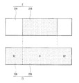
図4は、図3に示した正極21および負極22の平面構成を表している。なお、図4では、正極活物質層21Bおよび負極活物質層22Bの形成範囲に網掛けを施している。
FIG. 4 shows a planar configuration of the
この二次電池では、例えば、正極活物質層21Bが正極集電体21Aに対して部分的に設けられているのに対して、負極活物質層22Bは負極集電体22Aに対して全面的に設けられている。すなわち、負極活物質層22Bは、正極活物質層21Bの形成領域と対向する領域R1および対向しない領域R2の双方に設けられている。
In this secondary battery, for example, the positive electrode active material layer 21B is partially provided with respect to the positive electrode
この負極活物質層22Bでは、領域R1に設けられている部分が充放電に寄与し、領域R2に設けられている部分は充放電に寄与しないため、その領域R2では、負極活物質層22Bの状態が初期状態(二次電池の製造直後)のまま維持される。このことから、負極結着剤の炭化度は領域R2において充放電の影響を受けずに維持されるため、上記した比IC/INや比IN1/IN2は領域R2において測定されるのが好ましい。 In the negative electrode active material layer 22B, the portion provided in the region R1 contributes to charging / discharging, and the portion provided in the region R2 does not contribute to charging / discharging. Therefore, in the region R2, the portion of the negative electrode active material layer 22B The state is maintained in the initial state (immediately after manufacturing the secondary battery). From this, the carbonization degree of the negative electrode binder is maintained in the region R2 without being affected by charging / discharging, and thus the above-described ratio IC / IN and ratio IN1 / IN2 are preferably measured in the region R2.
セパレータ23は、正極21と負極22とを隔離し、両極の接触による電流の短絡を防止しつつリチウムイオンを通過させるものである。このセパレータ23は、例えば、ポリテトラフルオロエチレン、ポリプロピレンあるいはポリエチレンなどからなる合成樹脂製の多孔質膜、またはセラミック製の多孔質膜によって構成されており、それらの2種以上の多孔質膜を積層したものであってもよい。中でも、ポリオレフィン製の多孔質膜は、ショート防止効果に優れており、シャットダウン効果による電池の安全性向上を図ることができるので好ましい。特に、ポリエチレンは、100℃以上160℃以下でシャットダウン効果が得られると共に電気化学的安定性に優れているので好ましい。また、ポリプロピレンも好ましく、他にも化学的安定性を備えた樹脂であれば、ポリエチレンあるいはポリプロピレンと共重合させたものであったり、ブレンド化したものであってもよい。
The
このセパレータ23には、液状の電解質として電解液が含浸されている。この電解液は、溶媒と、それに溶解された電解質塩とを含んでいる。
The
溶媒は、例えば、有機溶剤などの非水溶媒のいずれか1種あるいは2種以上を含有している。この非水溶媒としては、例えば、炭酸エチレン、炭酸プロピレン、炭酸ブチレン、炭酸ジメチル、炭酸ジエチル、炭酸エチルメチル、γ−ブチロラクトン、γ−バレロラクトン、1,2−ジメトキシエタン、テトラヒドロフラン、2−メチルテトラヒドロフラン、1,3−ジオキソラン、4−メチル−1,3−ジオキソラン、酢酸メチル、プロピオン酸メチル、プロピオン酸エチル、アセトニトリル、グルタロニトリル、アジポニトリル、メトキシアセトニトリル、3−メトキシプロピオニトリル、N,N−ジメチルホルムアミド、N−メチルピロリジノン、N−メチルオキサゾリジノン、ニトロメタン、ニトロエタン、スルホラン、ジメチルスルホキシド、リン酸トリメチル、エチレンスルフィトあるいはビストリフルオロメチルスルホニルイミドトリメチルヘキシルアンモニウムなどが挙げられる。優れた容量、サイクル特性および保存特性が得られるからである。中でも、炭酸エチレン、炭酸プロピレン、炭酸ジメチル、炭酸ジエチルおよび炭酸エチルメチルからなる群のうちの少なくとも1種が好ましく、炭酸エチレンあるいは炭酸プロピレンなどの高粘度(高誘電率)溶媒(例えば比誘電率ε≧30)と炭酸ジメチル、炭酸ジエチルあるいは炭酸エチルメチルなどの低粘度溶媒(例えば粘度≦1mPa・s)とを混合したものが好ましい。電解質塩の解離性およびイオンの移動度が向上するため、より高い効果が得られるからである。 The solvent contains, for example, one or more of nonaqueous solvents such as organic solvents. Examples of the non-aqueous solvent include ethylene carbonate, propylene carbonate, butylene carbonate, dimethyl carbonate, diethyl carbonate, ethyl methyl carbonate, γ-butyrolactone, γ-valerolactone, 1,2-dimethoxyethane, tetrahydrofuran, and 2-methyltetrahydrofuran. 1,3-dioxolane, 4-methyl-1,3-dioxolane, methyl acetate, methyl propionate, ethyl propionate, acetonitrile, glutaronitrile, adiponitrile, methoxyacetonitrile, 3-methoxypropionitrile, N, N- Dimethylformamide, N-methylpyrrolidinone, N-methyloxazolidinone, nitromethane, nitroethane, sulfolane, dimethyl sulfoxide, trimethyl phosphate, ethylene sulfite or bistrifluoromethylsulfonyl And imidotrimethylhexylammonium. This is because excellent capacity, cycle characteristics and storage characteristics can be obtained. Among them, at least one member selected from the group consisting of ethylene carbonate, propylene carbonate, dimethyl carbonate, diethyl carbonate, and ethyl methyl carbonate is preferable, and a high-viscosity (high dielectric constant) solvent such as ethylene carbonate or propylene carbonate (for example, relative dielectric constant ε ≧ 30) and a low viscosity solvent such as dimethyl carbonate, diethyl carbonate or ethyl methyl carbonate (for example, viscosity ≦ 1 mPa · s) are preferably mixed. This is because the dissociation property of the electrolyte salt and the ion mobility are improved, so that a higher effect can be obtained.
この溶媒は、ハロゲンを構成元素として有する環状炭酸エステルのいずれか1種あるいは2種以上を含有しているのが好ましい。負極22にハロゲンを含む被膜が形成されて電解液の分解が抑制されるため、サイクル特性が向上するからである。このハロゲンを有する環状炭酸エステルは、例えば、化2で表される化合物である。
This solvent preferably contains one or more cyclic carbonates having halogen as a constituent element. This is because a coating film containing halogen is formed on the
化2に示した化合物としては、例えば、4−フルオロ−1,3−ジオキソラン−2−オンおよび4,5−ジフルオロ−1,3−ジオキソラン−2−オンのうちの少なくとも1種などが挙げられる。もちろん、化2に示した構造を有していれば、他の化合物であってもよい。特に、4,5−ジフルオロ−1,3−ジオキソラン−2−オンは、シス異性体よりもトランス異性体が好ましい。容易に入手可能であると共に、サイクル特性が十分に向上するからである。
Examples of the compound shown in
また、溶媒は、ハロゲンを構成元素として有する鎖状炭酸エステルのいずれか1種あるいは2種以上を含有していてもよい。ハロゲンを有する環状炭酸エステルと同様に負極22に被膜が形成されるため、サイクル特性が向上するからである。このハロゲンを有する鎖状炭酸エステルとしては、例えば、炭酸フルオロメチルメチル、炭酸ビス(フルオロメチル)あるいは炭酸ジフルオロメチルメチルなどが挙げられる。
Moreover, the solvent may contain any 1 type or 2 types or more of the chain | strand-shaped carbonate which has a halogen as a structural element. This is because the film is formed on the
また、溶媒は、不飽和結合を有する環状炭酸エステルのいずれか1種あるいは2種以上を含有していてもよい。サイクル特性が向上するからである。この不飽和結合を有する環状炭酸エステルとしては、例えば、炭酸ビニレンあるいは炭酸ビニルエチレンなどが挙げられる。 Moreover, the solvent may contain any 1 type or 2 types or more of the cyclic carbonate which has an unsaturated bond. This is because the cycle characteristics are improved. Examples of the cyclic carbonate having an unsaturated bond include vinylene carbonate and vinyl ethylene carbonate.
電解質塩は、例えば、リチウム塩などの軽金属塩のいずれか1種あるいは2種以上を含有している。このリチウム塩としては、例えば、六フッ化リン酸リチウム(LiPF6 )、過塩素酸リチウム(LiClO4 )、六フッ化ヒ酸リチウム(LiAsF6 )、ビス(ペンタフルオロエタンスルホニル)イミドリチウム(LiN(C2 F5 SO2 )2 )、トリフルオロメタンスルホン酸リチウム(LiCF3 SO3 )、ビス(トリフルオロメタンスルホニル)イミドリチウム(LiN(CF3 SO2 )2 )、リチウムトリス(トリフルオロメタンスルホニル)メチド(LiC(CF3 SO2 )3 )、塩化リチウム(LiCl)あるいは臭化リチウム(LiBr)などが挙げられる。優れた容量、サイクル特性および保存特性が得られるからである。中でも、六フッ化リン酸リチウムが好ましい。内部抵抗が低下するため、より高い効果が得られるからである。 The electrolyte salt contains, for example, one or more light metal salts such as a lithium salt. Examples of the lithium salt include lithium hexafluorophosphate (LiPF 6 ), lithium perchlorate (LiClO 4 ), lithium hexafluoroarsenate (LiAsF 6 ), lithium bis (pentafluoroethanesulfonyl) imide lithium (LiN). (C 2 F 5 SO 2 ) 2 ), lithium trifluoromethanesulfonate (LiCF 3 SO 3 ), bis (trifluoromethanesulfonyl) imidolithium (LiN (CF 3 SO 2 ) 2 ), lithium tris (trifluoromethanesulfonyl) methide (LiC (CF 3 SO 2 ) 3 ), lithium chloride (LiCl), lithium bromide (LiBr), and the like can be given. This is because excellent capacity, cycle characteristics and storage characteristics can be obtained. Among these, lithium hexafluorophosphate is preferable. This is because a higher effect can be obtained because the internal resistance is lowered.
この電解質塩は、四フッ化ホウ酸リチウムを含有しているのが好ましい。二次電池の膨れが抑制されるからである。特に、四フッ化ホウ酸リチウムを六フッ化リン酸リチウムと併用すれば、優れた容量やサイクル特性が得られると共に二次電池の膨れも抑制されるので好ましい。 This electrolyte salt preferably contains lithium tetrafluoroborate. This is because swelling of the secondary battery is suppressed. In particular, it is preferable to use lithium tetrafluoroborate in combination with lithium hexafluorophosphate, because excellent capacity and cycle characteristics can be obtained and swelling of the secondary battery is suppressed.
電解質塩の濃度は、溶媒に対して0.3mol/kg以上3.0mol/kg以下であるのが好ましい。この範囲外ではイオン伝導性が低下するため、十分な電池容量が得られない可能性があるからである。 The concentration of the electrolyte salt is preferably 0.3 mol / kg or more and 3.0 mol / kg or less with respect to the solvent. This is because, outside this range, ionic conductivity is lowered, so that a sufficient battery capacity may not be obtained.
なお、電解液は、溶媒および電解質塩の他に、各種添加剤を含有していてもよい。この添加剤としては、−SO2 −結合を有するスルホン化合物および−SO2 −O−結合を有するスルホン化合物のうちの少なくとも1種(以下、単に「スルホン化合物」ともいう。)が好ましい。二次電池の膨れが抑制されるからである。特に、スルホン化合物を四フッ化ホウ酸リチウムをと併用すれば、二次電池の膨れが著しく抑制されるので好ましい。 The electrolytic solution may contain various additives in addition to the solvent and the electrolyte salt. As this additive, at least one of a sulfone compound having a —SO 2 — bond and a sulfone compound having a —SO 2 —O— bond (hereinafter also simply referred to as “sulfone compound”) is preferable. This is because swelling of the secondary battery is suppressed. In particular, it is preferable to use a sulfone compound in combination with lithium tetrafluoroborate because the swelling of the secondary battery is remarkably suppressed.
このスルホン化合物としては、例えば、化3〜化7で表される化合物が挙げられる。これらは単独で用いられてもよいし、複数種が混合されて用いられてもよい。化3〜化7において炭素数を限定しているのは、優れた相溶性が得られるからである。
Examples of the sulfone compound include compounds represented by
上記した化3〜化7に示した化合物の代表例を挙げると、化4に示した化合物として化8で表される化合物、化6に示した化合物として化9で表される化合物、あるいは化7に示した化合物として化10で表される化合物などが挙げられる。もちろん、化3〜化7に示した構造を有していれば、他の化合物であってもよい。中でも、不飽和結合を有する少なくとも1つの炭素原子が硫黄原子に結合している化合物が好ましい。
Representative examples of the compounds shown in
電解液中におけるスルホン化合物の含有量は、任意に設定可能であるが、0.01重量%以上10重量%以下であるのが好ましい。二次電池の膨れが十分に抑制されるからである。 The content of the sulfone compound in the electrolytic solution can be arbitrarily set, but is preferably 0.01% by weight or more and 10% by weight or less. This is because swelling of the secondary battery is sufficiently suppressed.
この二次電池では、充電を行うと、例えば、正極21からリチウムイオンが放出され、セパレータ23に含浸された電解液を介して負極22に吸蔵される。一方、放電を行うと、例えば、負極22からリチウムイオンが放出され、セパレータ23に含浸された電解液を介して正極21に吸蔵される。
In the secondary battery, when charged, for example, lithium ions are extracted from the
この二次電池は、例えば、以下の手順によって製造される。 This secondary battery is manufactured, for example, by the following procedure.
最初に、正極集電体21Aの両面に正極活物質層21Bを形成して正極21を作製する。この場合には、例えば、正極活物質と、正極結着剤と、必要に応じて正極導電剤とを混合した正極合剤を溶剤に分散させてペースト状の正極合剤スラリーとし、正極集電体21Aの両面に均一に塗布して乾燥させたのち、ロールプレス機で圧縮成型して正極活物質層22Bを形成する。
First, the positive electrode active material layer 21B is formed on both surfaces of the positive electrode
また、上記した負極の製造手順と同様の手順により、負極集電体22Aの両面に負極活物質層22Bを形成して負極22を作製する。
In addition, the
次に、正極集電体21Aに正極リード25を溶接すると共に、負極集電体22Aに負極リード26を溶接したのち、セパレータ23を介して正極21と負極22とを巻回させて巻回電極体20を形成する。続いて、正極リード25の先端部を安全弁機構15に溶接すると共に負極リード26の先端部を電池缶11に溶接したのち、一対の絶縁板12,13で挟みながら巻回電極体20を電池缶11の内部に収納する。続いて、電池缶11の内部に電解液を注入してセパレータ23に含浸させる。最後に、電池缶11の開口端部に電池蓋14、安全弁機構15および熱感抵抗素子16をガスケット17を介してかしめて固定する。これにより、図2〜図4に示した二次電池が完成する。
Next, the
本実施の形態における二次電池およびその製造方法によれば、負極22が上記した負極と同様の手順によって作製され、同様の構成を有しているので、負荷特性やサイクル特性などの電池特性を向上させることができる。この場合には、負極22が高容量化に有利なケイ素やスズを含有する場合において電池特性が向上するため、炭素材料などを含有する場合よりも高い効果を得ることができる。
According to the secondary battery and the manufacturing method thereof in the present embodiment, since the
特に、電解液の溶媒がハロゲンを有する環状炭酸エステルを含有すれば、サイクル特性をより向上させることができる。また、電解液の電解質塩が四フッ化ホウ酸リチウムを含有し、あるいは電解液が添加剤として−SO2 −結合を有するスルホン化合物および−SO2 −O−結合を有するスルホン化合物のうちの少なくとも1種を含有すれば、膨れ特性を向上させることができる。 In particular, if the solvent of the electrolytic solution contains a cyclic carbonate having halogen, the cycle characteristics can be further improved. Further, the electrolyte salt of the electrolytic solution contains lithium tetrafluoroborate, or the electrolytic solution has at least one of a sulfone compound having a —SO 2 — bond and a sulfone compound having a —SO 2 —O— bond as an additive. If one kind is contained, the swollenness characteristics can be improved.
この二次電池およびその製造方法に関する他の効果は、上記した負極およびその製造方法について説明した場合と同様である。 Other effects relating to the secondary battery and the manufacturing method thereof are the same as those described for the negative electrode and the manufacturing method thereof.
(第2の電池)
図5は第2の電池の分解斜視構成を表しており、図6は図5に示した電池の主要部のVI−VI線に沿った断面構成を表している。この電池は、例えば、第1の実施の形態と同様にリチウムイオン二次電池である。
(Second battery)
FIG. 5 shows an exploded perspective configuration of the second battery, and FIG. 6 shows a cross-sectional configuration along the line VI-VI of the main part of the battery shown in FIG. This battery is, for example, a lithium ion secondary battery as in the first embodiment.
この二次電池は、主に、正極リード31および負極リード32が取り付けられた巻回電極体30をフィルム状の外装部材40の内部に収納したものである。このフィルム状の外装部材40を用いた電池構造は、ラミネートフィルム型と呼ばれている。
In this secondary battery, a
正極リード31および負極リード32は、例えば、それぞれ外装部材40の内部から外部に向かって同一方向に導出されている。正極リード31は、例えば、アルミニウムなどの金属材料によって構成されており、負極リード32は、例えば、銅、ニッケルあるいはステンレスなどの金属材料によって構成されている。正極リード31および負極リード32を構成する金属材料は、例えば、薄板状あるいは網目状になっている。
For example, the
外装部材40は、例えば、ナイロンフィルム、アルミニウム箔およびポリエチレンフィルムがこの順に貼り合わされた矩形状のアルミラミネートフィルムによって構成されている。この外装部材40では、例えば、ポリエチレンフィルムが巻回電極体30と対向していると共に、各外縁部が融着あるいは接着剤によって互いに密着している。外装部材40と正極リード31および負極リード32との間には、外気の侵入を防止するための密着フィルム41が挿入されている。この密着フィルム41は、正極リード31および負極リード32に対して密着性を有する材料、例えば、ポリエチレン、ポリプロピレン、変性ポリエチレンあるいは変性ポリプロピレンなどのポリオレフィン樹脂によって構成されている。
The
なお、外装部材40は、上記した3層構造のアルミラミネートフィルムに代えて、他の構造のラミネートフィルムによって構成されていてもよいし、またはポリプロピレンなどの高分子フィルムあるいは金属フィルムによって構成されていてもよい。
The
電極巻回体30は、正極33と負極34とがセパレータ35および電解質36を介して積層されてから巻回されたものであり、その最外周部は保護テープ37によって保護されている。
The
正極33は、例えば、正極集電体33Aの両面に正極活物質層33Bが設けられたものである。負極34は、上記した負極と同様の構成を有しており、例えば、負極集電体34Aの両面に負極活物質層34Bが設けられたものである。正極集電体33A、正極活物質層33B、負極集電体34A、負極活物質層34Bおよびセパレータ35の構成は、それぞれ上記した第1の電池における正極集電体21A、正極活物質層21B、負極集電体22A、負極活物質層22Bおよびセパレータ23の構成と同様である。
In the
電解質36は、電解液と、それを保持する高分子化合物とを含んでおり、いわゆるゲル状になっている。ゲル状の電解質は、高いイオン伝導率(例えば、室温で1mS/cm以上)が得られると共に漏液が防止されるので好ましい。
The
高分子化合物としては、例えば、ポリエチレンオキサイドあるいはポリエチレンオキサイドを含む架橋体などのエーテル系高分子化合物や、ポリメタクリレートなどのエステル系高分子化合物あるいはアクリレート系高分子化合物や、ポリフッ化ビニリデンあるいはフッ化ビニリデンとヘキサフルオロプロピレンとの共重合体などのフッ化ビニリデンの重合体などが挙げられる。これらは、単独で用いられてもよいし、複数種が混合されて用いられてもよい。特に、酸化還元安定性の点から、フッ化ビニリデンの重合体などのフッ素系高分子化合物などが好ましい。電解液中における高分子化合物の添加量は、両者の相溶性によっても異なるが、5質量%以上50質量%以下であるのが好ましい。 Examples of the polymer compound include an ether polymer compound such as polyethylene oxide or a crosslinked product containing polyethylene oxide, an ester polymer compound such as polymethacrylate or an acrylate polymer compound, polyvinylidene fluoride, or vinylidene fluoride. And a vinylidene fluoride polymer such as a copolymer of styrene and hexafluoropropylene. These may be used alone, or a plurality of types may be mixed and used. In particular, from the viewpoint of redox stability, a fluorine-based polymer compound such as a vinylidene fluoride polymer is preferable. The addition amount of the polymer compound in the electrolytic solution varies depending on the compatibility between the two, but is preferably 5% by mass or more and 50% by mass or less.
電解液の組成は、上記した第1の電池における電解液の組成と同様である。ただし、ここで言う溶媒とは、液状の溶媒だけでなく、電解質塩を解離させることが可能なイオン伝導性を有するものまで含む広い概念である。したがって、イオン伝導性を有する高分子化合物を用いる場合には、その高分子化合物も溶媒に含まれる。 The composition of the electrolytic solution is the same as the composition of the electrolytic solution in the first battery described above. However, the term “solvent” as used herein is a broad concept including not only a liquid solvent but also one having ion conductivity capable of dissociating an electrolyte salt. Accordingly, when a polymer compound having ion conductivity is used, the polymer compound is also included in the solvent.
なお、電解液を高分子化合物に保持させた電解質36に代えて、電解液をそのまま用いてもよい。この場合には、電解液がセパレータ35に含浸される。
Instead of the
この二次電池では、充電を行うと、例えば、正極33からリチウムイオンが放出され、電解質36を介して負極34に吸蔵される。一方、放電を行うと、負極34からリチウムイオンが放出され、電解質36を介して正極33に吸蔵される。
In the secondary battery, when charged, for example, lithium ions are extracted from the
ゲル状の電解質36を備えた二次電池は、例えば、以下の3種類の手順によって製造される。
The secondary battery including the
第1の製造方法では、最初に、上記した第1の電池の製造方法と同様の手順により、正極集電体33Aの両面に正極活物質層33Bを形成して正極33を作製すると共に、負極集電体34Aの両面に負極活物質層34Bを形成して負極34を作製する。続いて、電解液と、高分子化合物と、溶剤とを含む前駆溶液を調製して正極33および負極34に塗布したのち、溶剤を揮発させてゲル状の電解質36を形成する。続いて、正極集電体33Aに正極リード31を溶接すると共に、負極集電体34Aに負極リード32を溶接する。続いて、電解質36が形成された正極33と負極34とをセパレータ35を介して積層させてから長手方向に巻回し、その最外周部に保護テープ37を接着させて巻回電極体30を形成する。最後に、例えば、2枚のフィルム状の外装部材40の間に巻回電極体30を挟み込んだのち、その外装部材40の外縁部同士を熱融着などで接着させて巻回電極体30を封入する。この際、正極リード31および負極リード32と外装部材40との間に、密着フィルム41を挿入する。これにより、図5および図6に示した二次電池が完成する。
In the first manufacturing method, first, the positive electrode active material layer 33B is formed on both surfaces of the positive electrode
第2の製造方法では、最初に、正極33に正極リード31を溶接すると共に負極34に負極リード32を溶接したのち、正極33と負極34とをセパレータ35を介して積層してから巻回させると共に最外周部に保護テープ37を接着させて、巻回電極体30の前駆体である巻回体を形成する。続いて、2枚のフィルム状の外装部材40の間に巻回体を挟み込んだのち、一辺の外周縁部を除いた残りの外周縁部を熱融着などで接着させて袋状の外装部材40の内部に巻回体を収納する。続いて、電解液と、高分子化合物の原料であるモノマーと、重合開始剤と、必要に応じて重合禁止剤などの他の材料とを含む電解質用組成物を調製し、袋状の外装部材40の内部に注入したのち、その外装部材40の開口部を熱融着などで密封する。最後に、モノマーを熱重合させて高分子化合物とし、ゲル状の電解質36を形成する。これにより、二次電池が完成する。
In the second manufacturing method, first, the
第3の製造方法では、最初に、高分子化合物が両面に塗布されたセパレータ35を用いることを除き、上記した第1の製造方法と同様に、巻回体を形成して袋状の外装部材40の内部に収納する。このセパレータ35に塗布する高分子化合物としては、例えば、フッ化ビニリデンを成分とする重合体、すなわち単独重合体、共重合体あるいは多元共重合体などが挙げられる。具体的には、ポリフッ化ビニリデンや、フッ化ビニリデンとヘキサフルオロプロピレンとを成分とする二元系共重合体や、フッ化ビニリデンとヘキサフルオロプロピレンとクロロトリフルオロエチレンとを成分とする三元系共重合体などである。なお、高分子化合物は、上記したフッ化ビニリデンを成分とする重合体に加えて、他の1種あるいは2種以上の高分子化合物を含んでいてもよい。続いて、電解液を調製して外装部材40の内部に注入したのち、その外装部材40の開口部を熱融着などで密封する。最後に、外装部材40に加重をかけながら加熱し、高分子化合物を介してセパレータ35を正極33および負極34に密着させる。これにより、電解液が高分子化合物に含浸し、その高分子化合物がゲル化して電解質36が形成されるため、二次電池が完成する。
In the third manufacturing method, a wound body is formed by forming a wound body in the same manner as in the first manufacturing method described above, except that the
この第3の製造方法では、第1の製造方法と比較して、膨れ特性が改善される。また、第3の製造方法では、第2の製造方法と比較して、高分子化合物の原料であるモノマーや溶剤などが電解質36中にほとんど残らず、しかも高分子化合物の形成工程が良好に制御されるため、正極33、負極34およびセパレータ35と電解質36との間において十分な密着性が得られる。
In the third manufacturing method, the swollenness characteristics are improved as compared with the first manufacturing method. Further, in the third manufacturing method, compared to the second manufacturing method, there are hardly any monomers or solvents that are raw materials for the polymer compound remaining in the
本実施の形態における二次電池およびその製造方法によれば、負極34が上記した負極と同様の手順によって作製され、同様の構成を有しているので、負荷特性やサイクル特性などの電池特性を向上させることができる。他の効果は、上記した第1の電池について説明した場合と同様である。 According to the secondary battery and the manufacturing method thereof in the present embodiment, since the negative electrode 34 is manufactured by the same procedure as the negative electrode described above and has the same configuration, battery characteristics such as load characteristics and cycle characteristics are obtained. Can be improved. Other effects are the same as those described for the first battery.
本発明の具体的な実施例について詳細に説明する。 Specific examples of the present invention will be described in detail.
(実施例1−1)
以下の手順により、図5および図6に示したラミネートフィルム型の二次電池を製造した。この際、負極34の容量がリチウムの吸蔵および放出に基づいて表されるリチウムイオン二次電池となるようにした。
(Example 1-1)
The laminate film type secondary battery shown in FIGS. 5 and 6 was manufactured by the following procedure. At this time, a lithium ion secondary battery in which the capacity of the negative electrode 34 is expressed based on insertion and extraction of lithium was made.
まず、正極33を作製した。最初に、炭酸リチウム(Li2 CO3 )と炭酸コバルト(CoCO3 )とを0.5:1のモル比で混合したのち、空気中において900℃×5時間の条件で焼成してリチウムコバルト複合酸化物(LiCoO2 )を得た。続いて、正極活物質としてリチウムコバルト複合酸化物粉末(平均粒径10μm)95質量部と、正極結着剤としてポリフッ化ビニリデン粉末4質量部と、正極導電剤としてカーボンブラック粉末1質量部とを混合して正極合剤としたのち、N−メチル−2−ピロリドンに分散させてペースト状の正極合剤スラリーとした。続いて、アルミニウム箔(15μm厚)からなる正極集電体33の両面に正極合剤スラリーを均一に塗布して乾燥させたのち、ロールプレス機で圧縮成型して正極活物質層33Bを形成した。最後に、正極活物質層33Bが形成された正極集電体33Aを帯状に切断した。
First, the
次に、負極34を作製した。最初に、N−メチル−2−ピロリドンおよびN,N−ジメチルアセトアミドを溶媒とするポリアミック酸溶液を調製した。続いて、負極活物質としてケイ素粉末(平均粒径2μm)と、負極結着剤の前駆体としてポリアミック酸溶液とを80:20の乾燥重量比で混合したのち、N−メチル−2−ピロリドンに分散させて負極合剤スラリーとした。続いて、コーティング装置を用いて電解銅箔(15μm厚)からなる負極集電体34Aの両面に負極合剤スラリーを均一に塗布して乾燥させて負極活物質層34Bを形成した。この際、負極集電体34Aの片面側における負極活物質層34Bの厚さを20μmとした。続いて、真空雰囲気中において550℃×6時間の条件で負極活物質層34Bを加熱し、負極結着剤としてポリイミド(PI)を生成すると共に、そのポリイミドを炭化させた。最後に、負極活物質層34Bが形成された負極集電体34Aを帯状に切断した。
Next, the negative electrode 34 was produced. First, a polyamic acid solution using N-methyl-2-pyrrolidone and N, N-dimethylacetamide as solvents was prepared. Subsequently, after mixing silicon powder (
完成した負極34について、XPSを用いて負極活物質層34Bを表面分析したところ、炭素起因のスペクトル(C1s)の強度ICと窒素起因のスペクトル(N1s)の強度INとの比IC/INは15.0であり(ワイドスキャンスペクトル)、400.5eV近傍における窒素起因のスペクトル(N1s)の強度IN1と398.5eV近傍における窒素起因のスペクトル(N1s)の強度IN2との比IN1/IN2は3.0であった(ナロウスキャンスペクトル)。この際、測定装置としてアルバック−ファイ株式会社製のX線光電子分光装置(QUANTERA SXM)を用い、X線源として単色化Al−Kα(14.6eV)を用いた。 When the negative electrode active material layer 34B was subjected to surface analysis using the XPS for the completed negative electrode 34, the ratio IC / IN between the intensity IC of the spectrum derived from carbon (C1s) and the intensity IN of the spectrum derived from nitrogen (N1s) was 15 0.0 (wide scan spectrum), and the ratio IN1 / IN2 of the intensity IN1 of the spectrum (N1s) caused by nitrogen in the vicinity of 400.5 eV and the intensity IN2 of the spectrum (N1s) caused by nitrogen in the vicinity of 398.5 eV is 3. 0 (narrow scan spectrum). At this time, an X-ray photoelectron spectrometer (QUANTERA SXM) manufactured by ULVAC-PHI Co., Ltd. was used as the measuring device, and monochromated Al-Kα (14.6 eV) was used as the X-ray source.
次に、正極集電体33Aの一端にアルミニウム製の正極リード31を溶接すると共に、負極集電体34Aの一端にニッケル製の負極リード32を溶接した。続いて、正極33と、ポリエチレンからなる多孔質のセパレータ35(20μm厚)と、負極34と、セパレータ35とをこの順に積層してから長手方向に巻回させたのち、粘着テープからなる保護テープ37で巻き終わり部分を固定して、巻回電極体30の前駆体である巻回体を形成した。続いて、外側から、ナイロンフィルム(30μm厚)と、アルミニウム箔(40μm厚)と、無延伸ポリプロピレンフィルム(30μm厚)とが積層された3層構造のラミネートフィルム(総厚100μm)からなる2枚の外装部材40の間に巻回体を挟み込んだのち、一辺を除く外縁部同士を熱融着して袋状の外装部材40の内部に巻回体を収納した。続いて、溶媒として炭酸エチレン(EC)と炭酸ジエチル(DEC)とを混合したのち、電解質塩として六フッ化リン酸リチウム(LiPF6 )を溶解させて電解液を調製した。この際、溶媒の組成(EC:DEC)を重量比で30:70とし、電解液中における電解質塩の濃度を1mol/kgとした。続いて、外装部材40の開口部から電解液を注入し、セパレータ35に含浸させて巻回電極体50を形成した。
Next, the
最後に、真空雰囲気中において外装部材40の開口部を熱融着して封止することにより、厚さ3.8mm×幅34mm×高さ50mmのラミネートフィルム型の二次電池が完成した。
Finally, the opening of the
(実施例1−2〜1−6)
負極活物質層34Bの加熱温度を変更して、比IC/INおよび比IN1/IN2をそれぞれ15.5および2.8(600℃:実施例1−2)、28.0および1.3(700℃:実施例1−3)、30.0および1.1(800℃:実施例1−4)、34.0および0.9(900℃:実施例1−5)、あるいは35.0および0.5(950℃:実施例1−6)としたことを除き、実施例1−1と同様の手順を経た。なお、上記した括弧内の温度は負極活物質層34Bの加熱温度であり、以降においても同様である。
(Examples 1-2 to 1-6)
The heating temperature of the negative electrode active material layer 34B was changed so that the ratio IC / IN and the ratio IN1 / IN2 were 15.5 and 2.8 (600 ° C .: Example 1-2), 28.0 and 1.3 ( 700 ° C .: Example 1-3), 30.0 and 1.1 (800 ° C .: Example 1-4), 34.0 and 0.9 (900 ° C .: Example 1-5), or 35.0 And 0.5 (950 ° C .: Example 1-6). The same procedure as in Example 1-1 was performed. Note that the temperature in parentheses is the heating temperature of the negative electrode active material layer 34B, and the same applies to the following.
(比較例1−1)
負極活物質層34Bを加熱しなかったことを除き、実施例1−1と同様の手順を経た。この場合の比IC/INは、12.8であった。
(Comparative Example 1-1)
A procedure similar to that of Example 1-1 was performed except that the negative electrode active material layer 34B was not heated. The ratio IC / IN in this case was 12.8.
(比較例1−2〜1−5)
負極活物質層34Bの加熱温度を変更して、比IC/INを13.2(300℃:比較例1−2)、13.6(400℃:比較例1−3)、14.2(450℃:比較例1−4)とし、あるいは比IC/INおよび比IN1/IN2をそれぞれ14.5および3.8(500℃:比較例1−5)としたことを除き、実施例1−1と同様の手順を経た。
(Comparative Examples 1-2 to 1-5)
By changing the heating temperature of the negative electrode active material layer 34B, the ratio IC / IN was 13.2 (300 ° C .: Comparative Example 1-2), 13.6 (400 ° C .: Comparative Example 1-3), 14.2 ( 450 ° C .: Comparative Example 1-4), or except that the ratio IC / IN and the ratio IN1 / IN2 were 14.5 and 3.8 (500 ° C .: Comparative Example 1-5), respectively. 1 was followed.
これらの実施例1−1〜1−6および比較例1−1〜1−5の二次電池について、電池状態を安定化させるために初回充放電させたのち、抵抗特性、負荷特性およびサイクル特性を調べたところ、表1に示した結果が得られた。 For the secondary batteries of Examples 1-1 to 1-6 and Comparative Examples 1-1 to 1-5, after charging and discharging for the first time to stabilize the battery state, resistance characteristics, load characteristics, and cycle characteristics As a result, the results shown in Table 1 were obtained.
初回充放電の条件としては、0.2Cの定電流で電池電圧が4.25Vになるまで定電流定電圧充電し、電流が定電流時の5%に絞られたところで充電終了としたのち、0.2Cの定電流で電池電圧が2.7Vになるまで定電流放電した。上記した「0.2C」とは、理論容量を5時間で放電しきる電流値である。 As the condition of the first charge / discharge, the battery was charged at a constant current and a constant voltage until the battery voltage reached 4.25 V at a constant current of 0.2 C. After the current was reduced to 5% of the constant current, the charge was terminated. The battery was discharged at a constant current of 0.2 C until the battery voltage reached 2.7 V. The above-mentioned “0.2 C” is a current value at which the theoretical capacity can be discharged in 5 hours.
抵抗特性を調べる際には、日置電機株式会社製のテスタ(3561バッテリハイテスタ)を用いて、交流四端子法(1kH)によって内部抵抗を測定した。 When examining the resistance characteristics, the internal resistance was measured by an AC four-terminal method (1 kH) using a tester (3561 battery high tester) manufactured by Hioki Electric Co., Ltd.
負荷特性を調べる際には、以下の手順によって負荷試験を行って放電容量比を求めた。最初に、23℃の雰囲気中において、0.5Cの定電流で電池電圧が4.2Vになるまで定電流定電圧充電し、電流が定電流時の5%に絞られたところで充電終了としたのち、0.2Cの定電流で電池電圧が2.7Vになるまで定電流放電して、0.2C放電容量を測定した。続いて、同雰囲気中において、同条件で充電したのち、2Cの定電流で電池電圧が2.7Vになるまで定電流放電して、2C放電容量を測定した。最後に、放電容量比(%)=(2C放電容量/0.2C放電容量)×100を算出した。上記した「0.5C,2C」とは、それぞれ理論容量を2時間あるいは30分間で放電しきる電流値である。 When examining the load characteristics, a load test was performed according to the following procedure to obtain the discharge capacity ratio. First, in an atmosphere of 23 ° C., constant-current constant-voltage charging was performed at a constant current of 0.5 C until the battery voltage reached 4.2 V, and charging was terminated when the current was reduced to 5% of the constant current. After that, constant current discharge was performed until the battery voltage became 2.7 V at a constant current of 0.2 C, and the 0.2 C discharge capacity was measured. Subsequently, after charging under the same conditions in the same atmosphere, the battery was constant-current discharged at a constant current of 2C until the battery voltage reached 2.7 V, and the 2C discharge capacity was measured. Finally, discharge capacity ratio (%) = (2C discharge capacity / 0.2C discharge capacity) × 100 was calculated. The above-mentioned “0.5 C, 2 C” are current values at which the theoretical capacity can be completely discharged in 2 hours or 30 minutes, respectively.
サイクル特性を調べる際には、以下の手順によってサイクル試験を行って放電容量維持率を求めた。最初に、23℃の雰囲気中において、1Cの定電流で電池電圧が4.2Vになるまで定電流定電圧充電し、電流が定電流時の5%に絞られたところで充電終了としたのち、1Cの定電流で電池電圧が2.7Vになるまで定電流放電して、1サイクル目の放電容量を測定した。続いて、同雰囲気中において、充放電回数の合計が50回になるまで同条件で充放電を繰り返して、50サイクル目の放電容量を測定した。最後に、放電容量維持率(%)=(50サイクル目の放電容量/1サイクル目の放電容量)×100を算出した。 When examining the cycle characteristics, a cycle test was performed according to the following procedure to determine the discharge capacity retention rate. First, in an atmosphere of 23 ° C., a constant current and a constant voltage were charged at a constant current of 1 C until the battery voltage became 4.2 V. After the current was reduced to 5% of the constant current, the charging was terminated. A constant current was discharged at a constant current of 1 C until the battery voltage reached 2.7 V, and the discharge capacity at the first cycle was measured. Subsequently, in the same atmosphere, charging / discharging was repeated under the same conditions until the total number of times of charging / discharging reached 50 times, and the discharge capacity at the 50th cycle was measured. Finally, discharge capacity retention ratio (%) = (discharge capacity at the 50th cycle / discharge capacity at the first cycle) × 100 was calculated.
上記した一連の特性を調べる際の手順および条件は、以降においても同様である。 The procedure and conditions for examining the series of characteristics described above are the same in the following.
表1に示したように、負極結着剤としてポリイミドを用いた場合には、負極活物質層34Bを加熱しなかった比較例1−1を基準とすると、それを加熱した実施例1−1〜1−6および比較例1−2〜1−5では、加熱温度が高くなるにしたがって比IC/INが次第に大きくなる傾向を示した。この結果は、加熱温度が高くなると負極活物質層34B等の炭化反応が進行し、その加熱温度が分解温度以上になるとポリイミドの炭化反応が進行するため、炭素起因のスペクトル(C1s)の強度ICが窒素起因のスペクトル(N1s)の強度INに対して相対的に大きくなることを表している。 As shown in Table 1, when polyimide was used as the negative electrode binder, when Comparative Example 1-1 in which the negative electrode active material layer 34B was not heated was used as a reference, Example 1-1 in which it was heated In ˜1-6 and Comparative Examples 1-2 to 1-5, the ratio IC / IN tended to gradually increase as the heating temperature increased. This result shows that the carbonization reaction of the negative electrode active material layer 34B or the like proceeds when the heating temperature is increased, and the carbonization reaction of polyimide proceeds when the heating temperature is equal to or higher than the decomposition temperature. Therefore, the intensity IC of the spectrum (C1s) due to carbon Is relatively large with respect to the intensity IN of the nitrogen-derived spectrum (N1s).
また、加熱温度がポリイミドの分解温度(=約500℃)未満である比較例1−2〜1−4では、398.5eV近傍における窒素起因のスペクトル(N1s)が検出されなかったため、比IN1/IN2を算出することができなかった。これに対して、加熱温度がポリイミドの分解温度以上である実施例1−1〜1−6および比較例1−5では、398.5eV近傍における窒素起因のスペクトル(N1s)が検出されたため、比IN1/IN2を算出することができた。この場合には、加熱温度が高くなるにしたがって比IN1/IN2が次第に小さくなる傾向を示した。この結果は、加熱温度が分解温度よりも低いとポリイミドが炭化しないため、その炭化物に起因するスペクトル(398.5eV近傍における窒素起因のスペクトル)が生じないことを表している。また、加熱温度がポリイミドの分解温度以上であると、その加熱温度が高くなるにしたがって炭化物の形成量が多くなるため、400.5eV近傍における窒素起因のスペクトル(N1s)の強度IN1が398.5eV近傍における窒素起因のスペクトル(N1s)の強度IN2に対して相対的に小さくなることを表している。 Further, in Comparative Examples 1-2 to 1-4 in which the heating temperature is less than the decomposition temperature of polyimide (= about 500 ° C.), a spectrum (N1s) caused by nitrogen in the vicinity of 398.5 eV was not detected, and therefore the ratio IN1 / IN2 could not be calculated. In contrast, in Examples 1-1 to 1-6 and Comparative Example 1-5 in which the heating temperature is equal to or higher than the decomposition temperature of polyimide, a spectrum (N1s) caused by nitrogen in the vicinity of 398.5 eV was detected. IN1 / IN2 could be calculated. In this case, the ratio IN1 / IN2 tended to decrease gradually as the heating temperature increased. This result indicates that when the heating temperature is lower than the decomposition temperature, the polyimide does not carbonize, so that a spectrum caused by the carbide (a spectrum caused by nitrogen in the vicinity of 398.5 eV) does not occur. Further, when the heating temperature is equal to or higher than the decomposition temperature of the polyimide, the amount of carbide formed increases as the heating temperature increases. Therefore, the intensity IN1 of the spectrum (N1s) caused by nitrogen in the vicinity of 400.5 eV is 398.5 eV. This represents that the intensity is relatively smaller than the intensity IN2 of the spectrum (N1s) caused by nitrogen in the vicinity.
このような傾向が得られる中、比IC/INが15.0以上であると共に比IN1/IN2が3.0以下である実施例1−1〜1−6では、比IC/INが15.0未満であると共に比IN1/IN2が3.0超である比較例1−1〜1−5と比較して、内部抵抗が大幅に低下して60%を下回ったと共に、放電容量比および放電容量維持率がいずれも大幅に増加して80%を上回った。 In such a tendency, in Examples 1-1 to 1-6 in which the ratio IC / IN is 15.0 or more and the ratio IN1 / IN2 is 3.0 or less, the ratio IC / IN is 15. Compared with Comparative Examples 1-1 to 1-5 in which the ratio IN1 / IN2 is less than 0 and the ratio IN1 / IN2 is greater than 3.0, the internal resistance is significantly lower than 60%, and the discharge capacity ratio and the discharge The capacity maintenance rate increased significantly and exceeded 80%.
ただし、加熱温度が950℃以下である実施例1−1〜1−6では、負極34の物理的強度が十分に得られたため、二次電池を正常に組み立てることができたが、加熱温度が950℃を超えると、負極34の物理的強度が極端に低下して脆くなったため、二次電池を正常に組み立てることができなかった。この結果は、二次電池を安定に組み立てるためには、比IC/INが35.0以下、比IN1/IN2が0.5以上でなければならないことを表している。 However, in Examples 1-1 to 1-6 in which the heating temperature was 950 ° C. or less, the physical strength of the negative electrode 34 was sufficiently obtained, and thus the secondary battery could be normally assembled. When the temperature exceeded 950 ° C., the physical strength of the negative electrode 34 was extremely lowered and became brittle, so that the secondary battery could not be assembled normally. This result indicates that the ratio IC / IN must be 35.0 or less and the ratio IN1 / IN2 must be 0.5 or more in order to stably assemble the secondary battery.
これらのことから、本発明の二次電池では、負極結着剤としてポリイミドを含有する負極活物質層を形成し、そのポリイミドの分解温度以上の温度で負極活物質層を加熱した場合に、XPSを用いた負極活物質層の表面分析において比IC/INが15.0以上35.0以下であり、あるいは比IN1/IN2が0.5以上3.0以下であることにより、負極の抵抗特性が向上するため、負荷特性およびサイクル特性が向上することが確認された。この場合には、比IC/INが15.5以上34.0以下あるいは比IN1/IN2が0.9以上2.8以下であり、さらに比IC/INが28.0以上30.0以下あるいは比IN1/IN2が1.1以上1.3以下であれば、負荷特性およびサイクル特性がより向上することも確認された。 For these reasons, in the secondary battery of the present invention, when a negative electrode active material layer containing polyimide as a negative electrode binder is formed and the negative electrode active material layer is heated at a temperature equal to or higher than the decomposition temperature of the polyimide, XPS When the ratio IC / IN is 15.0 or more and 35.0 or less or the ratio IN1 / IN2 is 0.5 or more and 3.0 or less in the surface analysis of the negative electrode active material layer using the negative electrode, the resistance characteristics of the negative electrode Therefore, it was confirmed that the load characteristics and the cycle characteristics were improved. In this case, the ratio IC / IN is 15.5 or more and 34.0 or less, or the ratio IN1 / IN2 is 0.9 or more and 2.8 or less, and the ratio IC / IN is 28.0 or more and 30.0 or less. It was also confirmed that when the ratio IN1 / IN2 is 1.1 or more and 1.3 or less, load characteristics and cycle characteristics are further improved.
(実施例2−1,2−2)
ポリアミック酸溶液に代えてポリアミドイミド溶液を用い、負極結着剤としてポリアミドイミド(PAI)を生成したことを除き、実施例1−2,1−4と同様の手順を経た。
(Examples 2-1 and 2-2)
A procedure similar to that of Examples 1-2 and 1-4 was performed, except that a polyamideimide solution was used instead of the polyamic acid solution and polyamideimide (PAI) was produced as a negative electrode binder.
(比較例2−1,2−2)
実施例2−1,2−2と同様に負極結着剤としてポリアミドイミドを生成したことを除き、比較例1−2,1−5と同様の手順を経た。
(Comparative Examples 2-1 and 2-2)
The same procedure as in Comparative Examples 1-2 and 1-5 was performed except that polyamideimide was produced as a negative electrode binder as in Examples 2-1 and 2-2.
これらの実施例2−1,2−2および比較例2−1,2−2の二次電池について初回充放電後に抵抗特性、負荷特性およびサイクル特性を調べたところ、表2に示した結果が得られた。 Regarding the secondary batteries of Examples 2-1 and 2-2 and Comparative Examples 2-1 and 2-2, the resistance characteristics, the load characteristics, and the cycle characteristics were examined after the first charge / discharge. The results shown in Table 2 were obtained. Obtained.
表2に示したように、負極結着剤としてポリアミドイミドを用いた場合においても、表1に示した結果と同様の結果が得られた。すなわち、XPSを用いた負極活物質層34Bの表面分析において比IC/INが15.0以上35.0以下であると共に比IN1/IN2が0.5以上3.0以下である実施例2−1,2−2では、比IC/INおよび比IN1/IN2が範囲外である比較例2−1,2−2と比較して、内部抵抗が大幅に低下したと共に放電容量比および放電容量維持率が大幅に増加した。このことから、本発明の二次電池では、負極結着剤の種類を変更した場合においても負荷特性およびサイクル特性が向上することが確認された。 As shown in Table 2, when polyamideimide was used as the negative electrode binder, the same results as those shown in Table 1 were obtained. That is, in the surface analysis of the negative electrode active material layer 34B using XPS, the ratio IC / IN is 15.0 to 35.0 and the ratio IN1 / IN2 is 0.5 to 3.0. In 1 and 2-2, compared with Comparative Examples 2-1 and 2-2 in which the ratio IC / IN and the ratio IN1 / IN2 are out of the range, the internal resistance is significantly reduced and the discharge capacity ratio and the discharge capacity are maintained. The rate has increased significantly. From this, it was confirmed that in the secondary battery of the present invention, load characteristics and cycle characteristics are improved even when the type of the negative electrode binder is changed.
なお、ここでは負極結着剤としてポリアミドを用いた実施例を開示していない。しかしながら、ポリイミドあるいはポリアミドイミドを用いた場合において表1および表2に示した結果が得られたことからすれば、ポリアミドを用いた場合においても同様の結果が得られることは明らかである。 In addition, the Example using polyamide as a negative electrode binder is not disclosed here. However, when the results shown in Table 1 and Table 2 are obtained when polyimide or polyamideimide is used, it is clear that similar results can be obtained when polyamide is used.
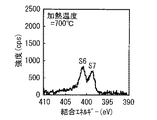
ここで、上記した一連の実施例および比較例を代表して、実施例1−3(加熱温度=700℃)および比較例1−1(未加熱),1−5(加熱温度=500℃)の二次電池について、XPSを用いて負極活物質層34Bを表面分析したところ、図7〜図12に示した結果が得られた。図7〜図9はワイドスキャンスペクトル(複数種の元素の結合状態)を表しており、それぞれ実施例1−3および比較例1−1,1−5の結果を示している。図10〜図12はナロウスキャンスペクトル(窒素の結合状態)を表しており、それぞれ実施例1−3および比較例1−1,1−5の結果を示している。 Here, on behalf of the series of Examples and Comparative Examples described above, Examples 1-3 (heating temperature = 700 ° C.) and Comparative Examples 1-1 (unheated), 1-5 (heating temperature = 500 ° C.) With respect to the secondary battery, the surface analysis of the negative electrode active material layer 34B was performed using XPS, and the results illustrated in FIGS. 7 to 12 were obtained. 7 to 9 show wide scan spectra (bonding states of plural kinds of elements), and show the results of Example 1-3 and Comparative Examples 1-1 and 1-5, respectively. 10 to 12 show narrow scan spectra (nitrogen bonding state), and show the results of Example 1-3 and Comparative Examples 1-1 and 1-5, respectively.
図7〜図9に示したように、実施例1−3および比較例1−1,1−5では、290eV近傍における炭素起因のスペクトルS1(C1s)と、400eV近傍における窒素起因のスペクトルS2(N1s)とが得られた。この場合には、さらに、100eV近傍におけるケイ素起因のスペクトルS3(Si2p)や、150eV近傍におけるケイ素起因のスペクトルS4(Si2s)や、520eV近傍における酸素起因のスペクトルS5(O1s)も得られた。しかしながら、スペクトルS2の強度に対するスペクトルS1の相対的な強度は、加熱温度を次第に高くした比較例1−1,1−5および実施例1−3の順に大きくなったため、比IC/INも同様の順に大きくなった。 As shown in FIGS. 7 to 9, in Example 1-3 and Comparative Examples 1-1 and 1-5, a spectrum S1 (C1s) caused by carbon in the vicinity of 290 eV and a spectrum S2 caused by nitrogen in the vicinity of 400 eV ( N1s). In this case, a spectrum S3 (Si2p) derived from silicon in the vicinity of 100 eV, a spectrum S4 (Si2s) derived from silicon in the vicinity of 150 eV, and a spectrum S5 (O1s) derived from oxygen in the vicinity of 520 eV were also obtained. However, since the relative intensity of the spectrum S1 with respect to the intensity of the spectrum S2 is increased in the order of Comparative Examples 1-1 and 1-5 and Example 1-3 in which the heating temperature is gradually increased, the ratio IC / IN is also the same. It became larger in order.
また、図10〜図12に示したように、実施例1−3および比較例1−1,1−5では、400.5eV近傍に窒素起因のスペクトルS6(N1s)が得られた。このスペクトルS6の強度は、負極活物質層34Bを加熱しなかった比較例1−1を基準とすると、加熱温度が500℃である比較例1−5では大きくなり、700℃である実施例1−3では小さくなった。この場合には、負極活物質層34Bを加熱しなかった比較例1−1(図11)では、スペクトルS6だけしか検出されなかったが、負極活物質層34Bを加熱した実施例1−3(図10)および比較例1−5(図12)では、スペクトルS6だけでなく、398.5eV近傍における窒素起因のスペクトルS7(N1s)も検出された。このスペクトルS7は、ポリイミドの炭化に起因するものであり、そのスペクトルS7の強度は、比較例1−5よりも実施例1−3において大きくなった。これにより、スペクトルS7が検出されなかった比較例1−1では、比IN1/IN2を算出することができなかったが、スペクトルS7が検出された実施例1−3および比較例1−5では、IN1/IN2を算出することができた。このIN1/IN2は、上記したスペクトルS6,S7間の相対的な大小関係により、比較例1−5よりも実施例1−3において小さくなった。 10 to 12, in Example 1-3 and Comparative Examples 1-1 and 1-5, a spectrum S6 (N1s) caused by nitrogen was obtained in the vicinity of 400.5 eV. The intensity of the spectrum S6 is increased in Comparative Example 1-5 where the heating temperature is 500 ° C. and is 700 ° C., based on Comparative Example 1-1 where the negative electrode active material layer 34B was not heated. It became small in -3. In this case, in Comparative Example 1-1 (FIG. 11) in which the negative electrode active material layer 34B was not heated, only the spectrum S6 was detected, but Example 1-3 (in which the negative electrode active material layer 34B was heated) In FIG. 10) and Comparative Example 1-5 (FIG. 12), not only the spectrum S6 but also a spectrum S7 (N1s) caused by nitrogen in the vicinity of 398.5 eV was detected. This spectrum S7 is caused by the carbonization of polyimide, and the intensity of the spectrum S7 is larger in Example 1-3 than in Comparative Example 1-5. Thereby, in Comparative Example 1-1 in which the spectrum S7 was not detected, the ratio IN1 / IN2 could not be calculated, but in Example 1-3 and Comparative Example 1-5 in which the spectrum S7 was detected, IN1 / IN2 could be calculated. This IN1 / IN2 was smaller in Example 1-3 than Comparative Example 1-5 due to the relative magnitude relationship between the above-described spectra S6, S7.
図7〜図12に示したXPSの測定結果から、XPSを用いた表面分析によって比IC/INおよび比IN1/IN2を算出できると共に、両者の比に基づいて電池特性の優劣を判定できることが確認された。 From the XPS measurement results shown in FIGS. 7 to 12, it is confirmed that the ratio IC / IN and the ratio IN1 / IN2 can be calculated by surface analysis using XPS, and the superiority or inferiority of the battery characteristics can be determined based on the ratio between the two. It was done.
(実施例3−1,3−2)
負極活物質層34B中に負極導電剤として黒鉛を含有させたことを除き、実施例1−2,1−4と同様の手順を経た。この場合には、ケイ素粉末とポリアミック酸溶液と黒鉛粉末とを70:20:10の乾燥重量比で混合した。
(Examples 3-1 and 3-2)
The same procedure as in Examples 1-2 and 1-4 was performed, except that graphite was included as the negative electrode conductive agent in the negative electrode active material layer 34B. In this case, silicon powder, polyamic acid solution, and graphite powder were mixed at a dry weight ratio of 70:20:10.
(比較例3−1,3−2)
実施例3−1,3−2と同様に負極活物質層34B中に負極導電剤を含有させたことを除き、比較例1−1,1−5と同様の手順を経た。
(Comparative Examples 3-1 and 3-2)
Similar to Examples 3-1 and 3-2, the same procedure as in Comparative Examples 1-1 and 1-5 was performed, except that the negative electrode conductive material was included in the negative electrode active material layer 34B.
これらの実施例3−1,3−2および比較例3−1,3−2の二次電池について初回充放電後に抵抗特性、負荷特性およびサイクル特性を調べたところ、表3に示した結果が得られた。 For the secondary batteries of Examples 3-1 and 3-2 and Comparative Examples 3-1 and 3-2, resistance characteristics, load characteristics, and cycle characteristics were examined after the first charge / discharge. The results shown in Table 3 were obtained. Obtained.
表3に示したように、負極活物質層34B中に負極導電剤を含有させた場合においても、表1に示した結果と同様の結果が得られた。すなわち、XPSを用いた負極活物質層34Bの表面分析において比IC/INが15.0以上35.0以下であると共に比IN1/IN2が0.5以上3.0以下である実施例3−1,3−2では、比IC/INおよび比IN1/IN2が範囲外である比較例3−1,3−2と比較して、内部抵抗が大幅に低下したと共に放電容量比および放電容量維持率が大幅に増加した。この場合には、負極導電剤の有無のみが異なる実施例1−4,3−2の比較から明らかなように、負極活物質層34Bが負極導電剤を含有する場合において内部抵抗がより低下すると共に放電容量比および放電容量維持率がより増加する傾向を示した。ただし、負極導電剤を用いることによって各特性値が向上する程度は僅かであり、比IC/INおよび比IN1/IN2を上記した範囲内に設定することによって各特性値が向上する程度には遠く及ばなかった。このことから、本発明の二次電池では、負極活物質層中に負極導電剤を含有させた場合においても負荷特性およびサイクル特性が向上すると共に、その場合には負荷特性およびサイクル特性がより向上することが確認された。 As shown in Table 3, when the negative electrode conductive material was included in the negative electrode active material layer 34B, the same results as those shown in Table 1 were obtained. That is, in the surface analysis of the negative electrode active material layer 34B using XPS, the ratio IC / IN is 15.0 to 35.0 and the ratio IN1 / IN2 is 0.5 to 3.0. In comparison with Comparative Examples 3-1 and 3-2 in which the ratio IC / IN and the ratio IN1 / IN2 are out of the range, the internal resistance is greatly reduced and the discharge capacity ratio and the discharge capacity are maintained. The rate has increased significantly. In this case, as is clear from the comparison of Examples 1-4 and 3-2 in which only the presence or absence of the negative electrode conductive agent is different, the internal resistance is further reduced when the negative electrode active material layer 34B contains the negative electrode conductive agent. In addition, the discharge capacity ratio and the discharge capacity retention rate tended to increase more. However, the degree to which each characteristic value is improved by using the negative electrode conductive agent is slight, and it is far from the degree to which each characteristic value is improved by setting the ratio IC / IN and the ratio IN1 / IN2 within the above ranges. It did not reach. Therefore, in the secondary battery of the present invention, load characteristics and cycle characteristics are improved even when a negative electrode conductive material is contained in the negative electrode active material layer, and in that case, load characteristics and cycle characteristics are further improved. Confirmed to do.
(実施例4−1)
溶媒として炭酸エチレンに代えてハロゲンを有する環状炭酸エステル(化2に示した化合物)である4−フルオロ−1,3−ジオキソラン−2−オン(FEC)を用いたことを除き、実施例1−4と同様の手順を経た。
(Example 4-1)
Example 1-except that 4-fluoro-1,3-dioxolan-2-one (FEC), which is a cyclic carbonate having a halogen instead of ethylene carbonate (compound shown in Chemical Formula 2), was used as a solvent. The same procedure as in No. 4 was performed.
(実施例4−2)
溶媒としてハロゲンを有する環状炭酸エステル(化2に示した化合物)であるトランス−4,5−ジフルオロ−1,3−ジオキソラン−2−オン(DFEC)を加えたことを除き、実施例1−4と同様の手順を経た。この際、溶媒の組成(EC:DEC:DFEC)を重量比で20:70:10とした。
(Example 4-2)
Example 1-4, except that trans-4,5-difluoro-1,3-dioxolan-2-one (DFEC), which is a cyclic carbonate having a halogen as a solvent (compound shown in Chemical Formula 2), was added. The same procedure was followed. At this time, the composition of the solvent (EC: DEC: DFEC) was 20:70:10 by weight.
これらの実施例4−1,4−2の二次電池について初回充放電後に抵抗特性、負荷特性およびサイクル特性を調べたところ、表4に示した結果が得られた。なお、表4には、実施例1−4の結果も併せて示している。 Regarding the secondary batteries of Examples 4-1 and 4-2, the resistance characteristics, the load characteristics, and the cycle characteristics were examined after the first charge / discharge, and the results shown in Table 4 were obtained. Table 4 also shows the results of Example 1-4.
表4に示したように、溶媒の組成を変更した場合においても、表1に示した結果と同様の結果が得られた。すなわち、XPSを用いた負極活物質層34Bの表面分析において比IC/INが15.0以上35.0以下であると共に比IN1/IN2が0.5以上3.0以下である実施例4−1,4−2では、実施例1−4と同様に高い内部抵抗、放電容量比および放電容量維持率が得られた。この場合には、溶媒がFEC,DFECを含有する場合において放電容量維持率が増加し、FECよりもDFECにおいて放電容量維持率がより増加する傾向を示した。これらのことから、本発明の二次電池では、溶媒にハロゲンを有する環状炭酸エステルを含有させれば負荷特性およびサイクル特性がより向上すると共に、モノハロゲン環状炭酸エステルよりもジハロゲン環状炭酸エステルを用いれば負荷特性およびサイクル特性がさらに向上することが確認された。 As shown in Table 4, even when the composition of the solvent was changed, the same results as those shown in Table 1 were obtained. That is, in the surface analysis of the negative electrode active material layer 34B using XPS, the ratio IC / IN is 15.0 to 35.0 and the ratio IN1 / IN2 is 0.5 to 3.0. In 1,4-2, a high internal resistance, a discharge capacity ratio, and a discharge capacity retention ratio were obtained as in Example 1-4. In this case, when the solvent contained FEC and DFEC, the discharge capacity retention rate increased, and the discharge capacity retention rate tended to increase more in DFEC than in FEC. For these reasons, in the secondary battery of the present invention, if a cyclic carbonate having halogen is contained in the solvent, load characteristics and cycle characteristics are further improved, and a dihalogen cyclic carbonate is used rather than a monohalogen cyclic carbonate. It was confirmed that the load characteristics and cycle characteristics were further improved.
(実施例5−1)
電解質塩として四フッ化ホウ酸リチウム(LiBF4 )を加えたことを除き、実施例1−4と同様の手順を経た。この際、電解液中における四フッ化ホウ酸リチウムの濃度を0.2mol/kgとした。
(Example 5-1)
The same procedure as in Example 1-4 was performed except that lithium tetrafluoroborate (LiBF 4 ) was added as the electrolyte salt. At this time, the concentration of lithium tetrafluoroborate in the electrolyte was 0.2 mol / kg.
(実施例5−2)
電解液に添加剤(−SO2 −O−結合を有するスルホン化合物)として化8に示した化合物を加えたことを除き、実施例1−4と同様の手順を経た。この際、電解液中におけるスルホン化合物の含有量を2重量%とした。この「重量%」とは、溶媒全体を100重量%とするときの値であり、以降においても同様である。
(Example 5-2)
A procedure similar to that in Example 1-4 was performed, except that the compound shown in Chemical Formula 8 was added as an additive (sulfone compound having a —SO 2 —O— bond) to the electrolytic solution. At this time, the content of the sulfone compound in the electrolytic solution was set to 2% by weight. The “wt%” is a value when the entire solvent is 100 wt%, and the same applies to the following.
(実施例5−3)
電解質塩として四フッ化ホウ酸リチウムを加え、電解液に添加剤(−SO2 −O−結合を有するスルホン化合物)として化8に示した化合物を加えたことを除き、実施例1−4と同様の手順を経た。この際、電解液中における四フッ化ホウ酸リチウムの濃度を0.2mol/kgとし、電解液中におけるスルホン化合物の含有量を2重量%とした。
(Example 5-3)
Except that lithium tetrafluoroborate was added as an electrolyte salt, and the compound shown in Chemical Formula 8 was added as an additive (sulfone compound having a —SO 2 —O— bond) to the electrolyte, Example 1-4 and A similar procedure was followed. At this time, the concentration of lithium tetrafluoroborate in the electrolytic solution was 0.2 mol / kg, and the content of the sulfone compound in the electrolytic solution was 2% by weight.
(実施例5−4)
電解液に添加剤(−SO2 −O−結合を有するスルホン化合物)として化8に示した化合物に代えて化9に示した化合物を加えたことを除き、実施例5−2と同様の手順を経た。
(Example 5-4)
The same procedure as in Example 5-2, except that the compound shown in Chemical Formula 9 was added instead of the compound shown in Chemical Formula 8 as an additive (sulfone compound having a —SO 2 —O— bond) to the electrolytic solution. It went through.
(実施例5−5)
電解液に添加剤(−SO2 −O−結合を有するスルホン化合物)として化8に示した化合物に代えて化9に示した化合物を加えたことを除き、実施例5−3と同様の手順を経た。
(Example 5-5)
The same procedure as in Example 5-3, except that the compound shown in Chemical Formula 9 was added instead of the compound shown in Chemical Formula 8 as an additive (sulfone compound having a —SO 2 —O— bond) to the electrolytic solution. It went through.
(実施例5−6)
電解液に添加剤として−SO2 −O−結合を有するスルホン化合物に代えて−SO2 −結合を有するスルホン化合物(化10に示した化合物)を加えたことを除き、実施例5−2と同様の手順を経た。
(Example 5-6)
Except that a sulfone compound having a —SO 2 — bond (compound shown in Chemical Formula 10) was added as an additive to the electrolyte solution instead of the sulfone compound having a —SO 2 —O— bond, Example 5-2 and A similar procedure was followed.
(実施例5−7)
電解液に添加剤として−SO2 −O−結合を有するスルホン化合物に代えて−SO2 −結合を有するスルホン化合物(化10に示した化合物)を加えたことを除き、実施例5−3と同様の手順を経た。
(Example 5-7)
Example 5-3 except that a sulfone compound having a —SO 2 — bond (compound shown in Chemical Formula 10) was added as an additive to the electrolyte solution instead of the sulfone compound having a —SO 2 —O— bond. A similar procedure was followed.
これらの実施例5−1〜5−7の二次電池について初回充放電後に抵抗特性、負荷特性およびサイクル特性を調べたところ、表5に示した結果が得られた。なお、表5には、実施例1−4の結果も併せて示している。 For the secondary batteries of Examples 5-1 to 5-7, the resistance characteristics, the load characteristics, and the cycle characteristics were examined after the first charge / discharge. The results shown in Table 5 were obtained. Table 5 also shows the results of Example 1-4.
実施例1−4,5−1〜5−7の二次電池については、以下の手順によって保存試験を行って膨れ特性も併せて調べた。最初に、23℃の雰囲気中において、0.5Cの定電流で電池電圧が4.2Vになるまで定電流定電圧充電し、電流が定電流時の5%に絞られたところで充電終了としたのち、保存前の厚さを測定した。続いて、充電状態のままで60℃の恒温槽中に24時間保存したのち、保存後の厚さを測定した。最後に、膨れ(mm)=保存後の厚さ−保存前の厚さを算出した。 For the secondary batteries of Examples 1-4 and 5-1 to 5-7, a storage test was performed according to the following procedure, and the swelling characteristics were also examined. First, in an atmosphere of 23 ° C., constant-current constant-voltage charging was performed at a constant current of 0.5 C until the battery voltage reached 4.2 V, and charging was terminated when the current was reduced to 5% of the constant current. After that, the thickness before storage was measured. Then, after storing for 24 hours in a 60 degreeC thermostat with a charge condition, the thickness after storage was measured. Finally, swelling (mm) = thickness after storage−thickness before storage was calculated.
表5に示したように、電解質塩の種類を変更したり、電解液に添加剤としてスルホン化合物を含有させた場合においても、表1に示した結果と同様の結果が得られた。すなわち、XPSを用いた負極活物質層34Bの表面分析において比IC/INが15.0以上35.0以下であると共に比IN1/IN2が0.5以上3.0以下である実施例5−1〜5−7では、実施例1−4と同様に高い内部抵抗、放電容量比および放電容量維持率が得られた。この場合には、電解質塩が四フッ化ホウ酸リチウムを含有し、あるいは電解液が添加剤としてスルホン化合物を含有する場合において膨れが減少し、双方を含有する場合において膨れが著しく減少する傾向を示した。より具体的には、スルホン化合物を含有する場合には、そのスルホン化合物の種類に依存せずに膨れがほぼ同等になり、四フッ化ホウ酸リチウムおよびスルホン化合物を含有する場合には、膨れがほとんど生じなくなった。これらのことから、本発明の二次電池では、電解質塩の種類を変更したり、電解液に添加剤を含有させても負荷特性およびサイクル特性が向上することが確認された。また、電解質塩に四フッ化ホウ酸リチウムを含有させたり、電解液に添加剤として−SO2 −結合を有するスルホン化合物および−SO2 −O−結合を有するスルホン化合物のうちの少なくとも1種を含有させれば膨れ特性が向上すると共に、双方を含有させれば膨れ特性が著しく向上することが確認された。 As shown in Table 5, the same results as those shown in Table 1 were obtained even when the type of the electrolyte salt was changed or the electrolyte solution contained a sulfone compound as an additive. That is, in the surface analysis of the negative electrode active material layer 34B using XPS, the ratio IC / IN is 15.0 to 35.0 and the ratio IN1 / IN2 is 0.5 to 3.0. In 1-5-7, the high internal resistance, the discharge capacity ratio, and the discharge capacity retention ratio were obtained as in Example 1-4. In this case, swelling tends to decrease when the electrolyte salt contains lithium tetrafluoroborate or the electrolyte contains a sulfone compound as an additive. Indicated. More specifically, in the case of containing a sulfone compound, the blisters are almost the same regardless of the type of the sulfone compound, and in the case of containing lithium tetrafluoroborate and a sulfone compound, the blisters are expanded. Almost no longer occurs. From these facts, it was confirmed that in the secondary battery of the present invention, load characteristics and cycle characteristics were improved even if the type of electrolyte salt was changed or an additive was added to the electrolytic solution. In addition, lithium tetrafluoroborate is contained in the electrolyte salt, or at least one of a sulfone compound having a —SO 2 — bond and a sulfone compound having a —SO 2 —O— bond as an additive in the electrolytic solution is used. It was confirmed that the swelling property was improved when contained, and the swelling property was remarkably improved when both were contained.
なお、ここでは添加剤として−SO2 −結合を有するスルホン化合物と−SO2 −O−結合を有するスルホン化合物とを併用した実施例を開示していない。しかしながら、上記した2種類のスルホン化合物を個別に用いた場合に膨れ特性が向上することは表5に示した結果から明らかであり、2種類のスルホン化合物を併用した場合に膨れが増大する特別な理由も見当たらない。したがって、2種類のスルホン化合物を併用した場合においても膨れ特性が向上することは明らかである。 Here, an example in which a sulfone compound having a —SO 2 — bond and a sulfone compound having a —SO 2 —O— bond as an additive are not disclosed. However, it is clear from the results shown in Table 5 that the swelling characteristics are improved when the above-mentioned two types of sulfone compounds are used individually. A special case in which swelling is increased when the two types of sulfone compounds are used in combination. I can't find any reason. Therefore, it is clear that the swelling characteristics are improved even when two types of sulfone compounds are used in combination.
上記した表1〜表5の結果から、負極結着剤としてイミド結合およびアミド結合のうちの少なくとも1種を有する樹脂を含有する負極活物質層を形成したのち、その樹脂の分解温度以上の温度で負極活物質層を加熱した場合に、XPSを用いた負極活物質層の表面分析において比IC/INが15.0以上35.0以下であり、あるいは比IN1/IN2が0.5以上3.0以下であることにより、負極結着剤の種類、溶媒の組成、電解質塩の種類、あるいは添加剤の有無などに依存せずに、負荷特性やサイクル特性などの電池特性が向上することが確認された。 From the results shown in Tables 1 to 5, after forming a negative electrode active material layer containing a resin having at least one of an imide bond and an amide bond as a negative electrode binder, a temperature equal to or higher than the decomposition temperature of the resin. In the surface analysis of the negative electrode active material layer using XPS, the ratio IC / IN is 15.0 or more and 35.0 or less, or the ratio IN1 / IN2 is 0.5 or more and 3 when the negative electrode active material layer is heated at 0.0 or less can improve battery characteristics such as load characteristics and cycle characteristics without depending on the type of negative electrode binder, the composition of the solvent, the type of electrolyte salt, or the presence or absence of additives. confirmed.
なお、表1〜表5では、電池構造としてラミネートフィルム型を例に挙げて実施例を開示しており、円筒型などの他の電池構造については実施例を開示していない。しかしながら、上記した効果は、イミド結合およびアミド結合のうちの少なくとも1種を有する樹脂の炭化度を適正化することによって得られ、電池構造に依存しないはずであるため、他の電池構造についても同様の効果が得られることは明らかである。 In Tables 1 to 5, examples are disclosed by taking a laminate film type as an example of the battery structure, and examples of other battery structures such as a cylindrical type are not disclosed. However, the effects described above are obtained by optimizing the carbonization degree of the resin having at least one of imide bond and amide bond, and should not depend on the battery structure. It is clear that the effect of can be obtained.
以上、実施の形態および実施例を挙げて本発明を説明したが、本発明は上記した実施の形態および実施例において説明した態様に限定されず、種々の変形が可能である。例えば、本発明の負極の使用用途は、必ずしも電池に限らず、電池以外の他の電気化学デバイスであっても良い。他の用途としては、例えば、キャパシタなどが挙げられる。 The present invention has been described with reference to the embodiments and examples. However, the present invention is not limited to the embodiments described in the above embodiments and examples, and various modifications can be made. For example, the use application of the negative electrode of the present invention is not necessarily limited to a battery, but may be an electrochemical device other than a battery. Other applications include, for example, capacitors.
また、上記した実施の形態および実施例では、本発明の電池の電解質として、電解液、あるいは電解液を高分子化合物に保持させたゲル状電解質を用いる場合について説明したが、他の種類の電解質を用いるようにしてもよい。他の電解質としては、例えば、イオン伝導性セラミックス、イオン伝導性ガラスあるいはイオン性結晶などのイオン伝導性無機化合物と電解液とを混合したものや、他の無機化合物と電解液とを混合したものや、それらの無機化合物とゲル状電解質とを混合したものなどが挙げられる。 In the above-described embodiments and examples, the case where the electrolyte solution or the gel electrolyte in which the electrolyte solution is held in a polymer compound is used as the electrolyte of the battery of the present invention has been described. May be used. Other electrolytes include, for example, a mixture of an ion conductive inorganic compound such as ion conductive ceramics, ion conductive glass or ionic crystal and an electrolyte, or a mixture of another inorganic compound and an electrolyte. Or a mixture of these inorganic compounds and a gel electrolyte.
また、上記した実施の形態および実施例では、本発明の電池として、負極の容量がリチウムの吸蔵および放出に基づいて表されるリチウムイオン二次電池について説明したが、必ずしもこれに限られるものではない。本発明の電池は、リチウムを吸蔵および放出することが可能な負極活物質の充電容量を正極活物質の充電容量よりも小さくすることにより、負極の容量がリチウムの吸蔵および放出に基づく容量とリチウムの析出および溶解に基づく容量とを含み、かつ、それらの容量の和によって表される二次電池についても同様に適用可能である。 In the above-described embodiments and examples, the lithium ion secondary battery in which the capacity of the negative electrode is expressed based on insertion and extraction of lithium is described as the battery of the present invention. However, the present invention is not necessarily limited to this. Absent. The battery of the present invention has a negative electrode active material capable of occluding and releasing lithium with a charge capacity smaller than that of the positive electrode active material. The present invention can be similarly applied to a secondary battery including a capacity based on the precipitation and dissolution of the metal, and represented by the sum of the capacities.
また、上記した実施の形態および実施例では、電極反応物質としてリチウムを用いる場合について説明したが、ナトリウム(Na)あるいはカリウム(K)などの他の短周期型周期表における1A族元素や、マグネシウムあるいはカルシウム(Ca)などの2A族元素や、アルミニウムなどの他の軽金属を用いてもよい。この場合においても、負極活物質として、上記実施の形態で説明した負極材料を用いることが可能である。 In the above-described embodiments and examples, the case where lithium is used as the electrode reactant has been described. However, the group 1A element in other short-period periodic tables such as sodium (Na) or potassium (K), magnesium, and the like Or 2A group elements, such as calcium (Ca), and other light metals, such as aluminum, may be used. Also in this case, the negative electrode material described in the above embodiment can be used as the negative electrode active material.
また、上記した実施の形態または実施例では、本発明の電池について、電池構造が円筒型およびラミネートフィルム型である場合、ならびに電池素子が巻回構造を有する場合を例に挙げて説明したが、本発明の電池は、角型、コイン型あるいはボタン型などの他の電池構造を有する場合や、電池素子が積層構造などの他の構造を有する場合についても同様に適用可能である。また、本発明の電池は、二次電池に限らず、一次電池などの他の種類の電池についても同様に適用可能である。 Further, in the above-described embodiment or example, the battery of the present invention has been described by taking the case where the battery structure is a cylindrical type and a laminate film type, and the case where the battery element has a winding structure as an example, The battery of the present invention can be similarly applied to a case where the battery has another battery structure such as a square shape, a coin shape or a button shape, or a case where the battery element has another structure such as a laminated structure. Further, the battery of the present invention is not limited to the secondary battery, but can be similarly applied to other types of batteries such as a primary battery.
また、上記した実施の形態および実施例では、本発明の負極あるいは電池における比IC/INについて、実施例の結果から導き出された数値範囲を適正範囲として説明しているが、その説明は、比IC/INが上記した範囲外となる可能性を完全に否定するものではない。すなわち、上記した適正範囲は、あくまで本発明の効果を得る上で特に好ましい範囲であり、本発明の効果が得られるのであれば、比IC/INが上記した範囲から多少外れてもよい。このことは、比IN1/IN2についても同様である。 Further, in the above-described embodiments and examples, the ratio IC / IN in the negative electrode or the battery of the present invention is described as an appropriate range of numerical values derived from the results of the examples. The possibility that IC / IN falls outside the above range is not completely denied. That is, the appropriate range described above is a particularly preferable range for obtaining the effects of the present invention, and the ratio IC / IN may slightly deviate from the above range as long as the effects of the present invention can be obtained. The same applies to the ratio IN1 / IN2.
1…負極集電体、2…負極活物質層、11…電池缶、12,13…絶縁板、14…電池蓋、15…安全弁機構、15A…ディスク板、16…熱感抵抗素子、17…ガスケット、20,30…巻回電極体、21,33…正極、21A,33A…正極集電体、21B,33B…正極活物質層、22,34…負極、22A,34A…負極集電体、22B,34B…負極活物質層、23,35…セパレータ、24…センターピン、25,31…正極リード、26,32…負極リード、36…電解質、37…保護テープ、40…外装部材、R1,R2…領域。
DESCRIPTION OF
Claims (13)
前記負極は、負極集電体上に、負極結着剤を含む負極活物質層を有し、
前記負極結着剤は、イミド結合およびアミド結合のうちの少なくとも1種を有する樹脂を含有し、
X線光電子分光法を用いた前記負極活物質層の表面分析(ナロウスキャンスペクトル)において、400.5eV近傍における窒素起因のスペクトル(N1s)の強度IN1と398.5eV近傍における窒素起因のスペクトル(N1s)の強度IN2との比IN1/IN2は、0.5以上3.0以下である、
二次電池。 An electrolyte is provided together with the positive electrode and the negative electrode,
The negative electrode has a negative electrode active material layer containing a negative electrode binder on a negative electrode current collector,
The negative electrode binder contains a resin having at least one of an imide bond and an amide bond,
In the surface analysis (narrow scan spectrum) of the negative electrode active material layer using X-ray photoelectron spectroscopy, the intensity IN1 of the nitrogen-derived spectrum (N1s) in the vicinity of 400.5 eV and the nitrogen-derived spectrum (N1s) in the vicinity of 398.5 eV ) Ratio IN1 / IN2 with respect to intensity IN2 is 0.5 or more and 3.0 or less,
Secondary battery.
請求項1記載の二次電池。The secondary battery according to claim 1.
請求項1記載の二次電池。The secondary battery according to claim 1.
請求項3記載の二次電池。The secondary battery according to claim 3.
請求項1記載の二次電池。 The resin is at least one member selected from the group consisting of polyimide, polyamide, and polyamideimide.
The secondary battery according to claim 1 .
請求項1記載の二次電池。 The negative electrode active material layer includes a negative electrode active material that can occlude and release an electrode reactant and contains a material having at least one of a metal element and a metalloid element.
The secondary battery according to claim 1 .
請求項6記載の二次電池。 The negative electrode active material is at least one member selected from the group consisting of a simple substance, an alloy and a compound of silicon, and a simple substance, an alloy and a compound of tin.
The secondary battery according to claim 6 .
請求項1記載の二次電池。The secondary battery according to claim 1.
負極集電体上に、イミド結合およびアミド結合のうちの少なくとも1種を有する樹脂を含有する負極結着剤、を含む負極活物質層を形成する工程と、
前記樹脂の分解温度以上の温度で前記負極活物質層を加熱する工程と
を含む、二次電池の製造方法。 The step of producing the negative electrode in a secondary battery provided with an electrolyte together with the positive electrode and the negative electrode,
Forming a negative electrode active material layer including a negative electrode binder containing a resin having at least one of an imide bond and an amide bond on the negative electrode current collector;
And heating the negative electrode active material layer at a temperature equal to or higher than the decomposition temperature of the resin.
請求項9記載の二次電池の製造方法。 Heating the negative electrode active material layer at a temperature lower than the melting point of the negative electrode current collector;
The manufacturing method of the secondary battery of Claim 9.
前記負極結着剤は、イミド結合およびアミド結合のうちの少なくとも1種を有する樹脂を含有し、
X線光電子分光法を用いた前記負極活物質層の表面分析(ナロウスキャンスペクトル)において、400.5eV近傍における窒素起因のスペクトル(N1s)の強度IN1と398.5eV近傍における窒素起因のスペクトル(N1s)の強度IN2との比IN1/IN2は、0.5以上3.0以下である、
二次電池用負極。 On the negative electrode current collector, it has a negative electrode active material layer containing a negative electrode binder,
The negative electrode binder contains a resin having at least one of an imide bond and an amide bond,
In the surface analysis (narrow scan spectrum) of the negative electrode active material layer using X-ray photoelectron spectroscopy, the intensity IN1 of the nitrogen-derived spectrum (N1s) in the vicinity of 400.5 eV and the nitrogen-derived spectrum (N1s) in the vicinity of 398.5 eV ) Ratio IN1 / IN2 with respect to intensity IN2 is 0.5 or more and 3.0 or less,
Negative electrode for secondary battery.
前記樹脂の分解温度以上の温度で前記負極活物質層を加熱する工程と
を含む、二次電池用負極の製造方法。 Forming a negative electrode active material layer including a negative electrode binder containing a resin having at least one of an imide bond and an amide bond on the negative electrode current collector;
And heating the negative electrode active material layer at a temperature equal to or higher than the decomposition temperature of the resin.
請求項12記載の二次電池用負極の製造方法。 Heating the negative electrode active material layer at a temperature lower than the melting point of the negative electrode current collector;
The manufacturing method of the negative electrode for secondary batteries of Claim 12 .
Priority Applications (1)
| Application Number | Priority Date | Filing Date | Title |
|---|---|---|---|
| JP2007200673A JP5358905B2 (en) | 2007-08-01 | 2007-08-01 | Negative electrode for secondary battery, secondary battery, and production method thereof |
Applications Claiming Priority (1)
| Application Number | Priority Date | Filing Date | Title |
|---|---|---|---|
| JP2007200673A JP5358905B2 (en) | 2007-08-01 | 2007-08-01 | Negative electrode for secondary battery, secondary battery, and production method thereof |
Publications (3)
| Publication Number | Publication Date |
|---|---|
| JP2009037842A JP2009037842A (en) | 2009-02-19 |
| JP2009037842A5 JP2009037842A5 (en) | 2010-09-16 |
| JP5358905B2 true JP5358905B2 (en) | 2013-12-04 |
Family
ID=40439570
Family Applications (1)
| Application Number | Title | Priority Date | Filing Date |
|---|---|---|---|
| JP2007200673A Expired - Fee Related JP5358905B2 (en) | 2007-08-01 | 2007-08-01 | Negative electrode for secondary battery, secondary battery, and production method thereof |
Country Status (1)
| Country | Link |
|---|---|
| JP (1) | JP5358905B2 (en) |
Families Citing this family (15)
| Publication number | Priority date | Publication date | Assignee | Title |
|---|---|---|---|---|
| FR2944149B1 (en) | 2009-04-06 | 2011-04-29 | Centre Nat Rech Scient | COMPOSITE ELECTRODE. |
| KR102098547B1 (en) * | 2010-01-18 | 2020-04-08 | 에네베이트 코포레이션 | Composite material film for electrochemical storage |
| US10461366B1 (en) | 2010-01-18 | 2019-10-29 | Enevate Corporation | Electrolyte compositions for batteries |
| US20120070745A1 (en) * | 2010-09-16 | 2012-03-22 | Samsung Sdi Co., Ltd. | Negative active material for rechargeable lithium battery and rechargeable lithium battery including the same |
| US9583757B2 (en) | 2010-12-22 | 2017-02-28 | Enevate Corporation | Electrodes, electrochemical cells, and methods of forming electrodes and electrochemical cells |
| JP5450478B2 (en) * | 2011-02-28 | 2014-03-26 | 株式会社日立製作所 | Non-aqueous secondary battery negative electrode and non-aqueous secondary battery |
| JPWO2012132154A1 (en) * | 2011-03-28 | 2014-07-24 | 日本電気株式会社 | Secondary battery |
| WO2012132153A1 (en) * | 2011-03-28 | 2012-10-04 | 日本電気株式会社 | Secondary battery |
| WO2012132152A1 (en) * | 2011-03-28 | 2012-10-04 | 日本電気株式会社 | Secondary battery and production method therefor |
| TW201312827A (en) * | 2011-09-13 | 2013-03-16 | Hitachi Maxell Energy Ltd | Lithium secondary-battery pack, electronic device using same, charging system, and charging method |
| KR101520158B1 (en) * | 2012-09-21 | 2015-05-13 | 주식회사 엘지화학 | Electrolyte solution for lithium secondary battery and lithium secondary battery comprising the same |
| EP3721489A1 (en) | 2017-12-07 | 2020-10-14 | Enevate Corporation | Composite comprising silicon carbide and carbon particles |
| US11133498B2 (en) | 2017-12-07 | 2021-09-28 | Enevate Corporation | Binding agents for electrochemically active materials and methods of forming the same |
| US10686214B2 (en) | 2017-12-07 | 2020-06-16 | Enevate Corporation | Sandwich electrodes and methods of making the same |
| JPWO2019171436A1 (en) * | 2018-03-05 | 2021-03-18 | 昭和電工マテリアルズ株式会社 | Electrochemical device |
Family Cites Families (1)
| Publication number | Priority date | Publication date | Assignee | Title |
|---|---|---|---|---|
| JP4033720B2 (en) * | 2002-06-19 | 2008-01-16 | 三洋電機株式会社 | Negative electrode for lithium secondary battery and lithium secondary battery |
-
2007
- 2007-08-01 JP JP2007200673A patent/JP5358905B2/en not_active Expired - Fee Related
Also Published As
| Publication number | Publication date |
|---|---|
| JP2009037842A (en) | 2009-02-19 |
Similar Documents
| Publication | Publication Date | Title |
|---|---|---|
| JP5358905B2 (en) | Negative electrode for secondary battery, secondary battery, and production method thereof | |
| JP6123858B2 (en) | Nonaqueous electrolyte secondary battery and separator | |
| JP5510084B2 (en) | Negative electrode for lithium ion secondary battery, lithium ion secondary battery, electric tool, electric vehicle and power storage system | |
| JP5177361B2 (en) | Negative electrode for secondary battery and secondary battery | |
| JP4836767B2 (en) | Lithium ion secondary battery | |
| JP4943242B2 (en) | Lithium ion secondary battery | |
| JP5109359B2 (en) | Nonaqueous electrolyte secondary battery | |
| JP2009038018A (en) | Secondary battery | |
| JP2008218385A (en) | Electrode, method for manufacturing the electrode, and battery | |
| JP5109329B2 (en) | Secondary battery | |
| JP2008098053A (en) | Battery | |
| JP4876495B2 (en) | Electrolyte for lithium ion secondary battery and lithium ion secondary battery | |
| JP2008016422A (en) | Electrolyte and battery using the same, electrolyte for square battery, and square battery using the same | |
| JP4968225B2 (en) | Non-aqueous electrolyte battery | |
| JP2007157536A (en) | Battery | |
| JP2010277827A (en) | Nonaqueous electrolyte, positive electrode, and nonaqueous electrolyte secondary battery using the nonaqueous electrolyte and the positive electrode | |
| US20100316908A1 (en) | Battery | |
| JP2008103148A (en) | Negative electrode and battery | |
| JP2010123331A (en) | Nonaqueous electrolyte secondary battery | |
| JP2012003994A (en) | Nonaqueous electrolyte battery and nonaqueous electrolyte | |
| JP2011044339A (en) | Nonaqueous electrolyte secondary battery | |
| JP2008293687A (en) | Electrolytic solution and battery | |
| JP4867218B2 (en) | Lithium ion secondary battery | |
| JP2011028860A (en) | Nonaqueous electrolyte secondary battery | |
| JP2010186689A (en) | Nonaqueous electrolyte secondary battery |
Legal Events
| Date | Code | Title | Description |
|---|---|---|---|
| A521 | Written amendment |
Free format text: JAPANESE INTERMEDIATE CODE: A523 Effective date: 20100802 |
|
| A621 | Written request for application examination |
Free format text: JAPANESE INTERMEDIATE CODE: A621 Effective date: 20100802 |
|
| A977 | Report on retrieval |
Free format text: JAPANESE INTERMEDIATE CODE: A971007 Effective date: 20120926 |
|
| A131 | Notification of reasons for refusal |
Free format text: JAPANESE INTERMEDIATE CODE: A131 Effective date: 20121002 |
|
| A521 | Written amendment |
Free format text: JAPANESE INTERMEDIATE CODE: A523 Effective date: 20121128 |
|
| TRDD | Decision of grant or rejection written | ||
| A01 | Written decision to grant a patent or to grant a registration (utility model) |
Free format text: JAPANESE INTERMEDIATE CODE: A01 Effective date: 20130806 |
|
| A61 | First payment of annual fees (during grant procedure) |
Free format text: JAPANESE INTERMEDIATE CODE: A61 Effective date: 20130819 |
|
| LAPS | Cancellation because of no payment of annual fees |