JP5355292B2 - Image processing apparatus and image processing method - Google Patents
Image processing apparatus and image processing method Download PDFInfo
- Publication number
- JP5355292B2 JP5355292B2 JP2009186152A JP2009186152A JP5355292B2 JP 5355292 B2 JP5355292 B2 JP 5355292B2 JP 2009186152 A JP2009186152 A JP 2009186152A JP 2009186152 A JP2009186152 A JP 2009186152A JP 5355292 B2 JP5355292 B2 JP 5355292B2
- Authority
- JP
- Japan
- Prior art keywords
- edge
- edge strength
- image processing
- directions
- value
- Prior art date
- Legal status (The legal status is an assumption and is not a legal conclusion. Google has not performed a legal analysis and makes no representation as to the accuracy of the status listed.)
- Active
Links
Images


Classifications
-
- G—PHYSICS
- G06—COMPUTING; CALCULATING OR COUNTING
- G06T—IMAGE DATA PROCESSING OR GENERATION, IN GENERAL
- G06T7/00—Image analysis
- G06T7/40—Analysis of texture
- G06T7/41—Analysis of texture based on statistical description of texture
- G06T7/44—Analysis of texture based on statistical description of texture using image operators, e.g. filters, edge density metrics or local histograms
Description
本発明は、画像からエッジ特徴量を抽出するための技術に関するものである。 The present invention relates to a technique for extracting an edge feature amount from an image.
画像からエッジ特徴を抽出することで、画像中の被写体を検出したり、電子部品の傾きを検出したり、良品・不良品を判定したりする技術が提案されている。特許文献1、特許文献2では、エッジ特徴として、画像内の各画素についてエッジ強度を方向毎に累積したエッジ方向ヒストグラムを用いる方法が提案されている。 Techniques have been proposed in which an edge feature is extracted from an image to detect a subject in the image, detect an inclination of an electronic component, and determine whether a product is non-defective or defective. Patent Documents 1 and 2 propose a method using an edge direction histogram in which edge strengths are accumulated for each direction for each pixel in an image as an edge feature.
エッジ方向ヒストグラムは、画像内の所定領域におけるエッジ方向の累積的な特徴をあらわすため、エッジの位置を直接検出する方法のようにノイズの影響を受けることなく、精度良く被写体の特徴をとらえることができる。以下に、エッジ方向ヒストグラムの算出方法を説明する。 Since the edge direction histogram represents the cumulative characteristics of the edge direction in a predetermined area in the image, it can accurately capture the characteristics of the subject without being affected by noise as in the method of directly detecting the edge position. it can. Below, the calculation method of an edge direction histogram is demonstrated.
図1は、画像内における局所領域、及びこの局所領域内における画素を説明する図である。図1において101は画像全体を示しており、102はこの画像101内における局所領域、103はこの局所領域102内における着目画素を示している。また、図1では、着目画素103の水平方向のエッジ強度をIh、垂直方向のエッジ強度をIvとしている。図2は、着目画素103と、その近傍8画素を示す図である。
FIG. 1 is a diagram for explaining a local region in an image and pixels in the local region. In FIG. 1, 101 indicates the entire image, 102 indicates a local region in the
係る状況下において先ず、着目画素103について、方向毎のエッジ強度Fnを算出する。エッジの方向は、図2に示す如く、d1〜d8で示す8方向とする。この場合、以下の式1を用いて、各方向のエッジ強度Fnを算出する。
Under such circumstances, first, the edge strength Fn for each direction is calculated for the pixel of

次に、図3の302に示す如く局所領域102内の各画素を走査して局所領域102内の各画素に着目画素103を当てはめて上記式1に基づいた計算処理を行い、各画素について8方向のエッジ強度を算出する。
Next, as shown by 302 in FIG. 3, each pixel in the
最後に、局所領域102内の全ての画素のエッジ強度を方向毎に加算し、局所領域102内のエッジ方向ヒストグラムを算出する。この際、特許文献3に示される方法(従来法A)、特許文献4に示される方法(従来法B)が用いられる。従来法Aとは、エッジ強度が最大の方向のみをエッジ方向ヒストグラムに加算する方法である。従来法Bとは、8方向全ての方向のエッジ強度をエッジ方向ヒストグラムに加算する方法である。以上のようにして算出したエッジ方向ヒストグラムの例を、図3の301に示す。このようにして算出したヒストグラムを以下、「局所領域エッジヒストグラム」と呼ぶ。
Finally, the edge strengths of all the pixels in the
本説明では、着目画素に対するエッジの方向数を8とし、各画素で必ず8方向のエッジ強度を算出する方法で説明したが、1つの方向に対するエッジ強度だけを算出する方法もある。この場合、以下の式2、式3によりエッジ強度dとエッジ方向θを算出する。 In this description, the number of edge directions with respect to the pixel of interest is set to 8, and the edge strength in each direction is always calculated for each pixel. However, there is also a method for calculating only the edge strength in one direction. In this case, the edge strength d and the edge direction θ are calculated by the following formulas 2 and 3.
![]()
![]()
![]()
![]()
検出対象の輪郭形状が非直線形状の場合、例えば人物検出における肩の部分のエッジ特徴について以下で説明する。図4の401は、人物が写っている画像400において、この人物の肩周辺の領域を示しており、図4ではこの領域401を拡大して示している。領域401中の着目画素402について上記式1を用いて算出した8方向のそれぞれについてのエッジ強度F1〜F8の分布を403に示す。なお、係る分布403は、1つの画素について求めたものであるので、これを「画素エッジヒストグラム」と呼ぶ。
When the contour shape of the detection target is a non-linear shape, for example, the edge feature of the shoulder portion in human detection will be described below.
この分布403からも分かるように、着目画素402については、d7の方向についてエッジ強度が最大となる。しかし、その周りの方向d6,d8,d1についてもエッジ強度が強くなっていることが分かる。実際に、人の肩部分のエッジは、1つの方向に対するエッジ強度が極端に強くなるような直線的な輪郭ではなく、丸みを帯びた輪郭となる。このため、エッジ特徴としてはある1方向だけのエッジ強度を特徴量として持つよりも、エッジ強度の強い複数の方向を特徴量として持つほうが、より検出対象の輪郭形状の特徴を正しく捉えることができるといえる。
As can be seen from this
これに対し、従来法Aでは、エッジ強度が最大となる方向、つまりこの場合には方向d7のエッジ強度だけを特徴量として取得し、局所領域エッジヒストグラムに加算する。このため、d7以外の方向におけるエッジ強度情報を破棄することになる。前述したように、検出対象が直線的な形状のものであれば従来法Aでも十分にエッジ特徴を捉えることが可能だが、人物や車などの非直線形状の被写体を検出対象とするような場合には、十分にエッジ特徴を捉えきれているとは言えない。 In contrast, in the conventional method A, only the edge strength in the direction where the edge strength is maximum, that is, in this case, the edge strength in the direction d7 is acquired as a feature amount and added to the local region edge histogram. For this reason, edge strength information in directions other than d7 is discarded. As described above, if the detection target has a linear shape, the conventional method A can sufficiently capture the edge feature, but the detection target is a non-linear object such as a person or a car. Is not enough to capture the edge features.
一方、従来法Bでは、8方向全ての方向のエッジ強度を局所領域エッジヒストグラムに加算する。この場合には、d2,d3,d4のように、エッジ強度が低い方向についてもエッジ強度が加算されてしまう。このようなエッジ強度の低い方向をも加算対象としてしまうと、局所領域エッジヒストグラムの分布がこれらの方向についてもある程度の強度をもつ分布となる。そのため、本来特徴として捉えたいエッジ方向(図4の例では、d1,d6,d7,d8)の強調度合いが小さくなってしまう場合がある。 On the other hand, in the conventional method B, edge strengths in all eight directions are added to the local region edge histogram. In this case, the edge strength is also added in the direction where the edge strength is low, such as d2, d3, d4. If such a direction with low edge strength is also added, the distribution of the local region edge histogram becomes a distribution having a certain level of strength in these directions. For this reason, the degree of enhancement in the edge direction (d1, d6, d7, d8 in the example of FIG. 4) that is originally supposed to be regarded as a feature may be reduced.
図5は、従来法Aで算出した局所領域エッジヒストグラム501と、従来法Bで算出した局所領域エッジヒストグラム502を示す図である。局所領域エッジヒストグラム501では、他の方向におけるエッジ強度に対してd7の強度が相対的に極端に強調された分布になっているのに対し、局所領域エッジヒストグラム502では、他の方向に比べd7の強度の強調度合いが小さくなっている。
FIG. 5 is a diagram showing a local
本発明は以上の課題に鑑みて成されたものであり、局所領域における勾配方向毎の勾配強度分布を特徴量として算出する際、輪郭が直線以外の形状に対しても正確に局所領域内の特徴を捉えた特徴量を取得する為の技術を提供することを目的とする。 The present invention has been made in view of the above problems, and when calculating the gradient intensity distribution for each gradient direction in the local region as a feature amount, the contour accurately includes a shape other than a straight line in the local region. It aims at providing the technique for acquiring the feature-value which caught the feature.
本発明の目的を達成するために例えば、本発明の画像処理装置は以下の構成を備える。即ち、入力画像中の局所領域における着目画素について、規定数の方向のそれぞれに対するエッジ強度を計算する計算手段と、
前記計算手段がそれぞれの方向について計算したエッジ強度の平均値を求め、前記規定数の方向のうち、該求めた平均値よりも大きいエッジ強度に対応する方向を選択する選択手段と、
前記選択手段が選択した方向について前記計算手段が計算したエッジ強度を、当該方向について前記計算手段が従前に計算したエッジ強度に累積加算することで、当該方向に対する累積エッジ強度値を更新する更新手段と、
前記局所領域を構成する全ての画素について前記計算手段、前記選択手段、前記更新手段による処理を行うことで得られる、前記規定数の方向のそれぞれに対する累積エッジ強度値を、前記局所領域におけるエッジ特徴量として出力する手段と
を備えることを特徴とする。
In order to achieve the object of the present invention, for example, an image processing apparatus of the present invention comprises the following arrangement. In other words, for the pixel of interest in the local region in the input image, calculation means for calculating the edge strength for each of the prescribed number of directions;
An average value of edge strengths calculated for each direction by the calculation means , and a selection means for selecting a direction corresponding to an edge strength larger than the determined average value among the prescribed number of directions ;
Update means for updating the cumulative edge strength value for the direction by cumulatively adding the edge strength calculated by the calculation means for the direction selected by the selection means to the edge strength previously calculated by the calculation means for the direction. When,
Cumulative edge intensity values for each of the prescribed number of directions obtained by performing processing by the calculating means, the selecting means, and the updating means for all the pixels constituting the local area are represented as edge features in the local area. And means for outputting as a quantity.
本発明の構成によれば、局所領域における勾配方向毎の勾配強度分布を特徴量として算出する際、輪郭が直線以外の形状に対しても正確に局所領域内の特徴を捉えた特徴量を取得することができる。 According to the configuration of the present invention, when the gradient intensity distribution for each gradient direction in the local region is calculated as the feature amount, the feature amount that accurately captures the feature in the local region is acquired even for a shape whose contour is not a straight line. can do.
以下、添付図面を参照し、本発明の好適な実施形態について説明する。なお、以下説明する実施形態は、本発明を具体的に実施した場合の一例を示すもので、特許請求の範囲に記載の構成の具体的な実施例の1つである。 Preferred embodiments of the present invention will be described below with reference to the accompanying drawings. The embodiment described below shows an example when the present invention is specifically implemented, and is one of the specific examples of the configurations described in the claims.
[第1の実施形態]
本実施形態では、画素毎に画素エッジヒストグラムを解析し、平均以上のエッジ強度を有する方向のエッジ強度のみを局所領域エッジヒストグラムに加算する。図6は、本実施形態に係る画像処理装置のハードウェア構成例を示すブロック図である。
[First Embodiment]
In the present embodiment, the pixel edge histogram is analyzed for each pixel, and only the edge strength in the direction having the edge strength equal to or higher than the average is added to the local region edge histogram. FIG. 6 is a block diagram illustrating a hardware configuration example of the image processing apparatus according to the present embodiment.
CPU604は、ROM605やRAM606に格納されているコンピュータプログラムやデータを用いて、画像処理装置全体の制御を行うと共に、画像処理装置が行うものとして後述する各処理を実行する。
The
ROM605には、画像処理装置の設定データやブートプログラムなどが格納されている。RAM606は、コンピュータ読み取り可能な記憶媒体の一例であり、外部記憶装置602からロードされたコンピュータプログラムやデータを一時的に記憶する為のエリアを有すると共に、CPU604が各種の処理を実行する際に用いるワークエリアを有する。即ち、RAM606は各種のエリアを適宜提供することができる。
The
入力部601は、マウスやキーボードなどにより構成されており、ユーザが操作することで各種の指示をCPU604に対して入力することができる。表示部603は、CRTや液晶画面などにより構成されており、CPU604による処理結果を画像や文字などでもって表示することができる。
The
外部記憶装置602は、コンピュータ読み取り可能な記憶媒体の一例であり、ハードディスクドライブ装置に代表される、大容量情報記憶装置である。外部記憶装置602には、OS(オペレーティングシステム)や、画像処理装置が行うものとして後述する各処理をCPU604に実行させるためのコンピュータプログラムやデータなどが保存されている。外部記憶装置602に保存されているコンピュータプログラムやデータは、CPU604による制御に従って適宜RAM606にロードされ、CPU604による処理対象となる。
The
607は上述の各部を繋ぐバスである。なお、本実施形態に係る画像処理装置に適用可能な装置の構成は、図6に示したものに限定するものではなく、様々な構成が考え得る。
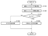
次に、1枚の画像中の局所領域からエッジ特徴量を抽出するための処理について、同処理のフローチャートを示す図7を用いて説明する。なお、図7に示したフローチャートに従った処理をCPU604に実行させるためのコンピュータプログラムやデータは、外部記憶装置602に保存されているので、CPU604はこれをRAM606に読み出して実行する。これにより、本実施形態に係る画像処理装置は、以下に説明する各処理を実行するように機能することになる。
Next, processing for extracting an edge feature amount from a local region in one image will be described with reference to FIG. 7 showing a flowchart of the processing. Note that since the computer program and data for causing the
先ず、ステップS701では、CPU604は、外部記憶装置602に保存されている画像をRAM606にロードする。なお、RAM606への画像の取得形態についてはこれに限定するものではなく、外部装置からネットワーク経由でRAM606に取得するようにしても良いし、本装置でアプリケーションを用いて作成した画像をそのまま以降の処理で用いるようにしても良い。本実施形態では、ステップS701でRAM606に取得した画像は、各画素がR、G、Bの色信号で構成されているカラー画像であるものとして説明する。
First, in step S <b> 701, the
次に、ステップS702では、CPU604は、ステップS701でRAM606に取得した画像に対する前処理として、この画像をグレイ画像に変換する。係る変換処理は、カラー画像の色成分をR、G、B、グレイ画像の色成分をYとすると、以下の式4に従った計算処理をカラー画像を構成する各画素について行うことで達成される。
Next, in step S702, the
![]()
![]()
なお、ステップS701で取得した画像がカラー画像ではない場合もあるので、ステップS702に先立ち、ステップS701で取得した画像がカラー画像か否かを先に判別する必要がある。係る判別は、画像がデジタルカメラにより取得したものである場合には、そのデータフォーマットを解析してカラー情報を参照することで行うことができる。また、画像がスキャナにより取得したものである場合には、ユーザにより設定されたスキャン条件を参照することで係る判別を行うことができる。以降の説明では、ステップS702で生成された画像を入力画像と呼称する。 Since the image acquired in step S701 may not be a color image, it is necessary to determine first whether or not the image acquired in step S701 is a color image prior to step S702. Such determination can be made by analyzing the data format and referring to the color information when the image is acquired by a digital camera. If the image is acquired by a scanner, the determination can be performed by referring to the scan condition set by the user. In the following description, the image generated in step S702 is referred to as an input image.
次に、ステップS703ではCPU604は、入力画像に対して局所領域を設定する。図8は、本実施形態において設定する局所領域を説明する図である。図8において800はステップS702で生成された入力画像、801はこの入力画像800に対してステップS703で設定する局所領域である。この局所領域801の左上隅の座標値は(Sx1,Sy1)、縦幅はH1(=6)、横幅はW1(=6)、であるとする。なお、局所領域の設定については、ユーザが入力部601を操作して設定しても良いし、予め定められた領域情報(例えば上述の座標値、縦幅、横幅を含む情報)を用いてCPU604が設定しても良い。
Next, in step S703, the
次に、ステップS704では、CPU604は、局所領域内のx座標値を示す変数xをSx1に初期化すると共に、局所領域内のy座標値を示す変数yをSy1に初期化する。即ち、係る初期化では、変数x、yの示す位置を、局所領域の左上隅の位置に初期化する。
Next, in step S704, the
次に、ステップS705では、CPU604は、ステップS702で生成された入力画像中の位置(x、y)における画素(着目画素)について、画素エッジヒストグラムを作成する。即ち上述の通り、着目画素から8方向(d1〜d8)のそれぞれへのエッジ強度Fn(n=1〜8)を計算する。ここでFnは、方向dnにおけるエッジ強度を示す。
Next, in step S705, the
エッジ強度Fnを算出する方法としては、上記で説明した方法の他、特登録02985893に開示の方法のように着目画素の周囲8画素に対して8種類のマスクパターンを適用することで求める方法を用いることもできる。図8において802は、8方向(d1〜d8)のそれぞれについて求めたエッジ強度(F1〜F8)を示す画素エッジヒストグラムの一例を示している。また、本実施形態では8方向を「規定数の方向」としているが、これ以外の数の方向を「規定数の方向」としても良い。
As a method for calculating the edge strength Fn, in addition to the method described above, a method for obtaining the edge strength Fn by applying eight types of mask patterns to eight pixels around the pixel of interest as in the method disclosed in Japanese Patent Registration 02985893 It can also be used. In FIG. 8,
次に、ステップS706では、CPU604は、ステップS705で求めたエッジ強度F1〜F8の平均値を計算し、この計算した平均値に基づいて、方向d1〜d8のうち1以上の方向を選択する。本ステップにおける処理の詳細については後述する。
Next, in step S706, the
次に、ステップS707では、CPU604は、ステップS706で選択した方向についてステップS705で計算したエッジ強度を、この方向について従前に計算したエッジ強度に累積加算することで、この方向に対する累積エッジ強度値を更新する。換言すれば、ステップS706で選択した方向のみについて、対応するエッジ強度を局所領域エッジヒストグラムに加える。
Next, in step S707, the
次に、ステップS708では、CPU604は、変数xに1を加える。そしてその後ステップS709では、ステップS708で更新した変数xが示すx座標値が、局所領域の右端を越えているか否かを判断すべく、以下の式が満たされているか否かを判断する。
Next, in step S708, the
![]()
![]()
係る判断の結果、満たされていると判断した場合には処理をステップS710に進める。一方、満たされていないと判断した場合には、処理をステップS705に戻し、以降の処理を繰り返す。 If it is determined that the condition is satisfied, the process proceeds to step S710. On the other hand, if it is determined that the condition is not satisfied, the process returns to step S705, and the subsequent processes are repeated.
ステップS710では、CPU604は、変数yに1を加えると共に、変数xをSx1に初期化する。そしてその後ステップS711では、ステップS710で更新した変数yが示すy座標値が、局所領域の下端を越えているか否かを判断すべく、以下の式6が満たされているか否かを判断する。
In step S710, the
![]()
![]()
係る判断の結果、満たされていると判断した場合には本処理を終了させる。一方、満たされていないと判断した場合には、処理をステップS705に戻し、以降の処理を繰り返す。 If it is determined that the condition is satisfied, the process is terminated. On the other hand, if it is determined that the condition is not satisfied, the process returns to step S705, and the subsequent processes are repeated.
次に、上記ステップS706における処理について説明する。ステップS706では、エッジ強度を求めた8方向のうち、着目画素のエッジ特徴を正しくあらわすために相対的にエッジ強度の強い方向を選択する。そのために本実施形態では、8方向のそれぞれについて計算したエッジ強度F1〜F8の平均(平均強度)を計算し、平均強度以上のエッジ強度を求めた方向を選択する。そして、選択した方向のエッジ強度のみを、局所領域エッジヒストグラムにおいて対応する累積エッジ強度に加算する。図9は、ステップS706における処理の詳細を示すフローチャートである。 Next, the process in step S706 will be described. In step S706, a direction having a relatively strong edge strength is selected from the eight directions for which the edge strength is obtained in order to correctly represent the edge feature of the pixel of interest. Therefore, in this embodiment, the average (average intensity) of the edge intensities F1 to F8 calculated for each of the eight directions is calculated, and the direction in which the edge intensity equal to or greater than the average intensity is selected. Then, only the edge strength in the selected direction is added to the corresponding cumulative edge strength in the local region edge histogram. FIG. 9 is a flowchart showing details of the processing in step S706.
先ずステップS901では、CPU604は、変数nを0に初期化する。次に、ステップS902では、CPU604は、上記ステップS705で8方向のそれぞれについて求めたエッジ強度F1〜F8の平均(平均強度)Aを、以下の式7を用いて計算する。
First, in step S901, the
次に、ステップS903では、CPU604は、変数nに1を加える。次に、ステップS904では、CPU604は、方向dnのエッジ強度Fnが平均強度Aよりも大きいか否かを判断するために、以下の式8が満たされているか否かを判断する。
Next, in step S903, the
![]()
![]()
係る判断の結果、満たされていると判断した場合には、処理をステップS905に進める、一方、満たされていないと判断した場合には、処理をステップS1906に進める。ステップS905では、CPU604は、局所領域エッジヒストグラムに登録されている「方向dnに対する累積エッジ強度」に、エッジ強度Fnを加え、この累積エッジ強度を更新する。
If it is determined that the condition is satisfied, the process proceeds to step S905. If it is determined that the condition is not satisfied, the process proceeds to step S1906. In step S905, the
一方、ステップS1906では、全てのエッジ強度F1〜F8について平均強度Aとの大小比較を行った否かを判断するために、以下の式9が満たされているか否かを判断する。 On the other hand, in step S1906, in order to determine whether or not all the edge strengths F1 to F8 are compared with the average strength A, it is determined whether or not the following Expression 9 is satisfied.
![]()
![]()
係る判断の結果、満たされていると判断した場合には、図9に示したフローチャートに従った処理を終了し、図7におけるステップS707に処理を進める。一方、満たされていないと判断した場合には、処理をステップS903に戻し、以降の処理を繰り返す。これにより、平均強度A以上のエッジ強度のみを、局所領域エッジヒストグラムに加算登録することができる。例えば、着目画素について、図10(a)に例示するような画素エッジヒストグラムが得られた場合、d1,d6,d7,d8の方向におけるエッジ強度F1,F6,F7,F8を局所領域エッジヒストグラムに加算することができる。 As a result of the determination, if it is determined that the condition is satisfied, the process according to the flowchart shown in FIG. 9 is terminated, and the process proceeds to step S707 in FIG. On the other hand, if it is determined that the condition is not satisfied, the process returns to step S903, and the subsequent processes are repeated. As a result, only edge intensities equal to or greater than the average intensity A can be added and registered in the local region edge histogram. For example, when the pixel edge histogram as illustrated in FIG. 10A is obtained for the pixel of interest, the edge intensities F1, F6, F7, and F8 in the directions of d1, d6, d7, and d8 are used as the local region edge histogram. Can be added.
なお、以上の処理により得られる局所領域エッジヒストグラムは、局所領域におけるエッジ特徴量として外部記憶装置602に対して出力する。しかし、局所領域エッジヒストグラムの出力先については特に限定するものではなく、ネットワーク経由で外部の装置に対して出力しても良いし、局所領域エッジヒストグラムを求めた後、この局所領域エッジヒストグラムを様々な処理に適用しても良い。
Note that the local region edge histogram obtained by the above processing is output to the
[第2の実施形態]
第1の実施形態では、平均強度以上のエッジ強度だけを局所領域エッジヒストグラムへの加算対象とした。しかし、画素エッジヒストグラムの分布が例えば、図10(b)に示すようにどの方向についても同程度のエッジ強度を持つような場合、全ての方向のエッジ強度を局所領域エッジヒストグラムへの加算対象とする方が、画素の特徴をあらわすのに適当である。そこで本実施形態では、エッジ強度F1〜F8の統計量として平均値と分散値とを用い、これらに基づいて、エッジ強度F1〜F8のうち局所領域エッジヒストグラムに加算する対象を決定する。即ち、本実施形態では、規定数の方向のうちエッジ強度の統計量が既定の条件を満たす方向を選択する方法において第1の実施形態とは異なる方法について説明する。
[Second Embodiment]
In the first embodiment, only edge strengths equal to or higher than the average strength are added to the local region edge histogram. However, when the distribution of the pixel edge histogram has, for example, the same edge strength in any direction as shown in FIG. 10B, the edge strength in all directions is added to the local region edge histogram. This is more suitable for expressing the characteristics of the pixel. Therefore, in the present embodiment, the average value and the variance value are used as the statistics of the edge strengths F1 to F8, and based on these, the target to be added to the local region edge histogram is determined among the edge strengths F1 to F8. That is, in the present embodiment, a method that is different from the first embodiment in a method for selecting a direction in which the statistical amount of edge strength satisfies a predetermined condition among a predetermined number of directions will be described.
なお、本実施形態は、上記ステップS706における処理、即ち、局所領域エッジヒストグラムへの加算対象エッジ強度の方向を決定する処理のみが第1の実施形態と異り、それ以外については第1の実施形態と同じである。従って、以下では、本実施形態においてステップS706において行う処理についてのみ説明する。図11は、本実施形態においてステップS706で行う処理のフローチャートである。 Note that the present embodiment is different from the first embodiment only in the processing in step S706, that is, the processing for determining the direction of the edge strength to be added to the local region edge histogram. Otherwise, the first embodiment. The form is the same. Therefore, only the process performed in step S706 in the present embodiment will be described below. FIG. 11 is a flowchart of the processing performed in step S706 in the present embodiment.
ステップS1201では、上記ステップS902における処理と同様にして、エッジ強度F1〜F8の平均値として平均強度Aを求める。次に、ステップS1202では、エッジ強度F1〜F8の分散値Vpを、以下の式10を用いて求める。 In step S1201, the average strength A is obtained as the average value of the edge strengths F1 to F8 in the same manner as the processing in step S902. Next, in step S1202, the variance values Vp of the edge strengths F1 to F8 are obtained using the following formula 10.
次に、ステップS1203では、分散値Vpが予め設定されている閾値thVよりも大きいか否かを判断するために、以下の式11が満たされているか否かを判断する。 Next, in step S1203, in order to determine whether or not the variance value Vp is larger than a preset threshold thV, it is determined whether or not the following Expression 11 is satisfied.
![]()
![]()
係る判断の結果、満たされていると判断した場合には、処理をステップS1205に進める。一方、満たされていない(閾値以下)と判断した場合には、処理をステップS1204に進める。ステップS1205では、第1の実施形態と同様に、平均強度A以上のエッジ強度のみを、対応する累積エッジ強度に加算する。一方、ステップS1204では、全てのエッジ強度F1〜F8を、対応する累積エッジ強度に加算する。 If it is determined that the condition is satisfied, the process advances to step S1205. On the other hand, if it is determined that it is not satisfied (below the threshold value), the process proceeds to step S1204. In step S1205, as in the first embodiment, only the edge strength equal to or greater than the average strength A is added to the corresponding accumulated edge strength. On the other hand, in step S1204, all the edge strengths F1 to F8 are added to the corresponding cumulative edge strength.
上記の処理により、エッジ強度の平均値と分散値に応じて局所領域エッジヒストグラムに加算するエッジ強度を決定するので、図10(a)のように数方向だけエッジ強度が強い特徴をもつ場合にはその方向のエッジ強度だけを局所領域エッジグラムに加算する。一方、図10(b)のように全ての方向に同程度のエッジ強度をもつ場合には、全ての方向のエッジ強度を局所領域エッジヒストグラムに加算する。 By the above processing, the edge strength to be added to the local region edge histogram is determined according to the average value and the variance value of the edge strength. Therefore, when the edge strength has a characteristic that is strong only in several directions as shown in FIG. Adds only the edge strength in that direction to the local region edgegram. On the other hand, as shown in FIG. 10B, in the case where the edge strengths are about the same in all directions, the edge strengths in all directions are added to the local region edge histogram.
また、本発明は、以下の処理を実行することによっても実現される。即ち、上述した実施形態の機能を実現するソフトウェア(プログラム)を、ネットワーク又は各種記憶媒体を介してシステム或いは装置に供給し、そのシステム或いは装置のコンピュータ(またはCPUやMPU等)がプログラムを読み出して実行する処理である。 The present invention can also be realized by executing the following processing. That is, software (program) that realizes the functions of the above-described embodiments is supplied to a system or apparatus via a network or various storage media, and a computer (or CPU, MPU, or the like) of the system or apparatus reads the program. It is a process to be executed.
Claims (6)
前記計算手段がそれぞれの方向について計算したエッジ強度の平均値を求め、前記規定数の方向のうち、該求めた平均値よりも大きいエッジ強度に対応する方向を選択する選択手段と、
前記選択手段が選択した方向について前記計算手段が計算したエッジ強度を、当該方向について前記計算手段が従前に計算したエッジ強度に累積加算することで、当該方向に対する累積エッジ強度値を更新する更新手段と、
前記局所領域を構成する全ての画素について前記計算手段、前記選択手段、前記更新手段による処理を行うことで得られる、前記規定数の方向のそれぞれに対する累積エッジ強度値を、前記局所領域におけるエッジ特徴量として出力する手段と
を備えることを特徴とする画像処理装置。 A calculation means for calculating an edge strength for each of a prescribed number of directions for a pixel of interest in a local region in an input image;
An average value of edge strengths calculated for each direction by the calculation means , and a selection means for selecting a direction corresponding to an edge strength larger than the determined average value among the prescribed number of directions ;
Update means for updating the cumulative edge strength value for the direction by cumulatively adding the edge strength calculated by the calculation means for the direction selected by the selection means to the edge strength previously calculated by the calculation means for the direction. When,
Cumulative edge intensity values for each of the prescribed number of directions obtained by performing processing by the calculating means, the selecting means, and the updating means for all the pixels constituting the local area are represented as edge features in the local area. An image processing apparatus comprising: means for outputting as a quantity.
前記計算手段がそれぞれの方向について求めたエッジ強度の分散値、及び平均値を求め、前記分散値が閾値よりも大きい場合には、前記平均値よりも大きいエッジ強度に対応する方向を選択し、前記分散値が閾値以下である場合には、前記規定数の方向の全てを選択する選択手段と、
前記選択手段が選択した方向について前記計算手段が計算したエッジ強度を、当該方向について前記計算手段が従前に計算したエッジ強度に累積加算することで、当該方向に対する累積エッジ強度値を更新する更新手段と、
前記局所領域を構成する全ての画素について前記計算手段、前記選択手段、前記更新手段による処理を行うことで得られる、前記規定数の方向のそれぞれに対する累積エッジ強度値を、前記局所領域におけるエッジ特徴量として出力する手段と
を備えることを特徴とする画像処理装置。 A calculation means for calculating an edge strength for each of a prescribed number of directions for a pixel of interest in a local region in an input image;
The calculation means obtains a dispersion value and an average value of the edge strength obtained for each direction, and when the dispersion value is larger than a threshold value, selects a direction corresponding to the edge strength larger than the average value, If the variance value is less than or equal to a threshold value, selection means for selecting all of the prescribed number of directions ;
Update means for updating the cumulative edge strength value for the direction by cumulatively adding the edge strength calculated by the calculation means for the direction selected by the selection means to the edge strength previously calculated by the calculation means for the direction. When,
Cumulative edge intensity values for each of the prescribed number of directions obtained by performing processing by the calculating means, the selecting means, and the updating means for all the pixels constituting the local area are represented as edge features in the local area. Means to output as quantity
The image processing apparatus comprising: a.
前記画像処理装置の計算手段が、入力画像中の局所領域における着目画素について、規定数の方向のそれぞれに対するエッジ強度を計算する計算工程と、
前記画像処理装置の選択手段が、前記計算工程でそれぞれの方向について計算したエッジ強度の平均値を求め、前記規定数の方向のうち、該求めた平均値よりも大きいエッジ強度に対応する方向を選択する選択工程と、
前記画像処理装置の更新手段が、前記選択工程で選択した方向について前記計算工程で計算したエッジ強度を、当該方向について前記計算工程で従前に計算したエッジ強度に累積加算することで、当該方向に対する累積エッジ強度値を更新する更新工程と、
前記画像処理装置の出力手段が、前記局所領域を構成する全ての画素について前記計算工程、前記選択工程、前記更新工程による処理を行うことで得られる、前記規定数の方向のそれぞれに対する累積エッジ強度値を、前記局所領域におけるエッジ特徴量として出力する工程と
を備えることを特徴とする画像処理方法。 An image processing method performed by an image processing apparatus,
A calculation step in which the calculation means of the image processing device calculates the edge intensity for each of the prescribed number of directions for the pixel of interest in the local region in the input image;
The selection unit of the image processing apparatus obtains an average value of edge strengths calculated for each direction in the calculation step, and selects a direction corresponding to an edge strength larger than the obtained average value among the prescribed number of directions. A selection process to select;
The update means of the image processing apparatus adds the edge strength calculated in the calculation step for the direction selected in the selection step to the edge strength calculated in the calculation step for the direction in the cumulative direction. An update process for updating the cumulative edge strength value;
Accumulated edge strength for each of the specified number of directions obtained by the output means of the image processing device performing the processing in the calculation step, the selection step, and the update step for all the pixels constituting the local region And a step of outputting a value as an edge feature quantity in the local region.
前記画像処理装置の計算手段が、入力画像中の局所領域における着目画素について、規定数の方向のそれぞれに対するエッジ強度を計算する計算工程と、A calculation step in which the calculation means of the image processing device calculates the edge intensity for each of the prescribed number of directions for the pixel of interest in the local region in the input image;
前記画像処理装置の選択手段が、前記計算工程でそれぞれの方向について求めたエッジ強度の分散値、及び平均値を求め、前記分散値が閾値よりも大きい場合には、前記平均値よりも大きいエッジ強度に対応する方向を選択し、前記分散値が閾値以下である場合には、前記規定数の方向の全てを選択する選択工程と、The selection means of the image processing device obtains a variance value and an average value of edge strength obtained in each direction in the calculation step, and when the variance value is larger than a threshold value, an edge larger than the average value Selecting a direction corresponding to intensity, and if the variance value is less than or equal to a threshold, a selection step of selecting all of the prescribed number of directions;
前記画像処理装置の更新手段が、前記選択工程で選択した方向について前記計算工程で計算したエッジ強度を、当該方向について前記計算工程で従前に計算したエッジ強度に累積加算することで、当該方向に対する累積エッジ強度値を更新する更新工程と、The update means of the image processing apparatus adds the edge strength calculated in the calculation step for the direction selected in the selection step to the edge strength calculated in the calculation step for the direction in the cumulative direction. An update process for updating the cumulative edge strength value;
前記画像処理装置の出力手段が、前記局所領域を構成する全ての画素について前記計算工程、前記選択工程、前記更新工程による処理を行うことで得られる、前記規定数の方向のそれぞれに対する累積エッジ強度値を、前記局所領域におけるエッジ特徴量として出力する工程とAccumulated edge strength for each of the specified number of directions obtained by the output means of the image processing device performing the processing in the calculation step, the selection step, and the update step for all the pixels constituting the local region Outputting a value as an edge feature amount in the local region;
を備えることを特徴とする画像処理方法。An image processing method comprising:
Priority Applications (2)
| Application Number | Priority Date | Filing Date | Title |
|---|---|---|---|
| JP2009186152A JP5355292B2 (en) | 2009-08-10 | 2009-08-10 | Image processing apparatus and image processing method |
| US12/844,641 US8355582B2 (en) | 2009-08-10 | 2010-07-27 | Image processing apparatus and image processing method |
Applications Claiming Priority (1)
| Application Number | Priority Date | Filing Date | Title |
|---|---|---|---|
| JP2009186152A JP5355292B2 (en) | 2009-08-10 | 2009-08-10 | Image processing apparatus and image processing method |
Publications (3)
| Publication Number | Publication Date |
|---|---|
| JP2011039752A JP2011039752A (en) | 2011-02-24 |
| JP2011039752A5 JP2011039752A5 (en) | 2012-09-27 |
| JP5355292B2 true JP5355292B2 (en) | 2013-11-27 |
Family
ID=43534885
Family Applications (1)
| Application Number | Title | Priority Date | Filing Date |
|---|---|---|---|
| JP2009186152A Active JP5355292B2 (en) | 2009-08-10 | 2009-08-10 | Image processing apparatus and image processing method |
Country Status (2)
| Country | Link |
|---|---|
| US (1) | US8355582B2 (en) |
| JP (1) | JP5355292B2 (en) |
Families Citing this family (2)
| Publication number | Priority date | Publication date | Assignee | Title |
|---|---|---|---|---|
| WO2010045038A1 (en) * | 2008-10-14 | 2010-04-22 | Dolby Laboratories Licensing Corporation | High dynamic range display with rear modulator control |
| JP2012141691A (en) * | 2010-12-28 | 2012-07-26 | Fujitsu Ten Ltd | Video processing device |
Family Cites Families (14)
| Publication number | Priority date | Publication date | Assignee | Title |
|---|---|---|---|---|
| JP2985893B2 (en) | 1990-08-30 | 1999-12-06 | グローリー工業株式会社 | Pattern recognition device |
| JP2766118B2 (en) | 1992-04-14 | 1998-06-18 | 松下電器産業株式会社 | Tilt detection method |
| JPH06266840A (en) * | 1993-03-11 | 1994-09-22 | Hitachi Ltd | Status detector for moving object |
| US5923430A (en) * | 1993-06-17 | 1999-07-13 | Ultrapointe Corporation | Method for characterizing defects on semiconductor wafers |
| JPH0772909A (en) | 1993-09-07 | 1995-03-17 | Fuji Facom Corp | Supporting device for programmable controller |
| JP3390896B2 (en) * | 1995-06-15 | 2003-03-31 | 富士通株式会社 | Feature extraction method |
| FR2766044B1 (en) * | 1997-07-11 | 1999-10-08 | Ge Medical Syst Sa | PROCESS FOR PROCESSING A SEQUENCE OF RADIOLOGICAL IMAGES OF AN OBJECT |
| JP2002175528A (en) | 2000-09-29 | 2002-06-21 | Matsushita Electric Ind Co Ltd | Method and device for extracting image information |
| US7092584B2 (en) * | 2002-01-04 | 2006-08-15 | Time Warner Entertainment Company Lp | Registration of separations |
| US7742634B2 (en) * | 2005-03-15 | 2010-06-22 | Omron Corporation | Image processing method, three-dimensional position measuring method and image processing apparatus |
| JP2007108835A (en) * | 2005-10-11 | 2007-04-26 | Keyence Corp | Image processor |
| JP4580324B2 (en) * | 2005-10-28 | 2010-11-10 | グローリー株式会社 | Image classification apparatus and image classification method |
| JP2008139262A (en) * | 2006-12-05 | 2008-06-19 | Omron Corp | Detect inspection method and inspection apparatus using the same |
| JP2009239394A (en) * | 2008-03-26 | 2009-10-15 | Seiko Epson Corp | Coloring image generating apparatus and method |
-
2009
- 2009-08-10 JP JP2009186152A patent/JP5355292B2/en active Active
-
2010
- 2010-07-27 US US12/844,641 patent/US8355582B2/en active Active
Also Published As
| Publication number | Publication date |
|---|---|
| US20110033117A1 (en) | 2011-02-10 |
| JP2011039752A (en) | 2011-02-24 |
| US8355582B2 (en) | 2013-01-15 |
Similar Documents
| Publication | Publication Date | Title |
|---|---|---|
| Lin et al. | Intensity and edge based adaptive unsharp masking filter for color image enhancement | |
| EP3236418B1 (en) | Image processing apparatus, image processing method, and storage medium | |
| JP6547386B2 (en) | Image processing apparatus and method | |
| US20100329533A1 (en) | Image processing method and image processing apparatus | |
| WO2013168618A1 (en) | Image processing device and image processing method | |
| JP4459795B2 (en) | Specific subject detection device | |
| US20210133473A1 (en) | Learning apparatus and learning method | |
| JP2009541838A (en) | Method, system and computer program for determining a threshold in an image including image values | |
| US10692215B2 (en) | Image processing apparatus, image processing method, and storage medium | |
| US20060008131A1 (en) | Image processing method, apparatus and program | |
| US20040042647A1 (en) | Image processing apparatus, method and memory medium | |
| JP5355292B2 (en) | Image processing apparatus and image processing method | |
| JP2005020338A (en) | Method, apparatus and program for detecting abnormal shadow | |
| US20100260386A1 (en) | Image processing apparatus and control method of image processing apparatus | |
| JP4804382B2 (en) | Image processing method, image processing program, and image processing apparatus | |
| JP5203159B2 (en) | Image processing method, image processing system, and image processing program | |
| JP4742068B2 (en) | Image processing method, image processing system, and image processing program | |
| CN110796629B (en) | Image fusion method and system | |
| WO2021009804A1 (en) | Method for learning threshold value | |
| JP4230960B2 (en) | Image processing apparatus, image processing method, and image processing program | |
| JP5910637B2 (en) | Biological image analysis system, biological image analysis method, and biological image analysis program | |
| JPH1196380A (en) | Feature amount extracting method, feature extracting device, image discriminating method, image discriminating device and storage medium | |
| JP4741289B2 (en) | Image processing apparatus and image processing method | |
| KR101874950B1 (en) | Recursive active contour segmentation for 3d cone beam CT and CT device using with the same | |
| JP2005094452A (en) | Method, system, and program for processing image |
Legal Events
| Date | Code | Title | Description |
|---|---|---|---|
| A521 | Written amendment |
Free format text: JAPANESE INTERMEDIATE CODE: A523 Effective date: 20120808 |
|
| A621 | Written request for application examination |
Free format text: JAPANESE INTERMEDIATE CODE: A621 Effective date: 20120808 |
|
| A977 | Report on retrieval |
Free format text: JAPANESE INTERMEDIATE CODE: A971007 Effective date: 20130426 |
|
| A131 | Notification of reasons for refusal |
Free format text: JAPANESE INTERMEDIATE CODE: A131 Effective date: 20130510 |
|
| A521 | Written amendment |
Free format text: JAPANESE INTERMEDIATE CODE: A523 Effective date: 20130709 |
|
| TRDD | Decision of grant or rejection written | ||
| A01 | Written decision to grant a patent or to grant a registration (utility model) |
Free format text: JAPANESE INTERMEDIATE CODE: A01 Effective date: 20130729 |
|
| A61 | First payment of annual fees (during grant procedure) |
Free format text: JAPANESE INTERMEDIATE CODE: A61 Effective date: 20130827 |
|
| R151 | Written notification of patent or utility model registration |
Ref document number: 5355292 Country of ref document: JP Free format text: JAPANESE INTERMEDIATE CODE: R151 |