JP5349073B2 - Water electrolysis equipment - Google Patents
Water electrolysis equipment Download PDFInfo
- Publication number
- JP5349073B2 JP5349073B2 JP2009033788A JP2009033788A JP5349073B2 JP 5349073 B2 JP5349073 B2 JP 5349073B2 JP 2009033788 A JP2009033788 A JP 2009033788A JP 2009033788 A JP2009033788 A JP 2009033788A JP 5349073 B2 JP5349073 B2 JP 5349073B2
- Authority
- JP
- Japan
- Prior art keywords
- water
- separator
- hydrogen
- flow path
- communication hole
- Prior art date
- Legal status (The legal status is an assumption and is not a legal conclusion. Google has not performed a legal analysis and makes no representation as to the accuracy of the status listed.)
- Expired - Fee Related
Links
Images


Classifications
-
- Y—GENERAL TAGGING OF NEW TECHNOLOGICAL DEVELOPMENTS; GENERAL TAGGING OF CROSS-SECTIONAL TECHNOLOGIES SPANNING OVER SEVERAL SECTIONS OF THE IPC; TECHNICAL SUBJECTS COVERED BY FORMER USPC CROSS-REFERENCE ART COLLECTIONS [XRACs] AND DIGESTS
- Y02—TECHNOLOGIES OR APPLICATIONS FOR MITIGATION OR ADAPTATION AGAINST CLIMATE CHANGE
- Y02E—REDUCTION OF GREENHOUSE GAS [GHG] EMISSIONS, RELATED TO ENERGY GENERATION, TRANSMISSION OR DISTRIBUTION
- Y02E60/00—Enabling technologies; Technologies with a potential or indirect contribution to GHG emissions mitigation
- Y02E60/30—Hydrogen technology
- Y02E60/36—Hydrogen production from non-carbon containing sources, e.g. by water electrolysis
Description
本発明は、電解質膜の両側に給電体が設けられるとともに、前記給電体にセパレータが積層されるとともに、一方の給電体と一方のセパレータとの間には、水を供給する第1流路が形成され、他方の給電体と他方のセパレータとの間には、前記水が電気分解されて得られる水素を流動させる第2流路が形成される水電解装置に関する。 In the present invention, a power feeding body is provided on both sides of the electrolyte membrane, a separator is stacked on the power feeding body, and a first flow path for supplying water is provided between one power feeding body and one separator. The present invention relates to a water electrolysis apparatus in which a second flow path is formed between the other power supply body and the other separator, in which hydrogen obtained by electrolyzing the water flows.
例えば、固体高分子型燃料電池は、アノード側電極に燃料ガス(主に水素を含有するガス、例えば、水素ガス)が供給される一方、カソード側電極に酸化剤ガス(主に酸素を含有するガス、例えば、空気)が供給されることにより、直流の電気エネルギを得ている。 For example, in a polymer electrolyte fuel cell, a fuel gas (a gas containing mainly hydrogen, such as hydrogen gas) is supplied to the anode side electrode, while an oxidant gas (mainly containing oxygen) is supplied to the cathode side electrode. By supplying a gas (for example, air), direct current electric energy is obtained.
一般的に、燃料ガスである水素ガスを製造するために、水電解装置が採用されている。この水電解装置は、水を分解して水素(及び酸素)を発生させるため、固体高分子電解質膜を用いている。固体高分子電解質膜の両面には、電極触媒層が設けられて電解質膜・電極構造体が構成されるとともに、前記電解質膜・電極構造体の両側には、給電体を配設してユニットが構成されている。すなわち、ユニットは、実質的には、上記の燃料電池と同様に構成されている。 In general, a water electrolysis apparatus is employed to produce hydrogen gas that is a fuel gas. This water electrolysis apparatus uses a solid polymer electrolyte membrane in order to decompose water and generate hydrogen (and oxygen). Electrode catalyst layers are provided on both sides of the solid polymer electrolyte membrane to form an electrolyte membrane / electrode structure, and a power feeder is provided on both sides of the electrolyte membrane / electrode structure. It is configured. That is, the unit is configured substantially in the same manner as the above fuel cell.
そこで、複数のユニットが積層された状態で、積層方向両端に電圧が付与されるとともに、アノード側給電体に水が供給される。このため、電解質膜・電極構造体のアノード側では、水が分解されて水素イオン(プロトン)が生成され、この水素イオンが固体高分子電解質膜を透過してカソード側に移動し、電子と結合して水素が製造される。一方、アノード側では、水素と共に生成された酸素が、余剰の水を伴ってユニットから排出される。 Therefore, in a state where a plurality of units are stacked, a voltage is applied to both ends in the stacking direction, and water is supplied to the anode-side power feeding body. For this reason, water is decomposed and hydrogen ions (protons) are generated on the anode side of the electrolyte membrane / electrode structure, and the hydrogen ions permeate the solid polymer electrolyte membrane and move to the cathode side to bond with electrons. Thus, hydrogen is produced. On the other hand, on the anode side, oxygen produced together with hydrogen is discharged from the unit with excess water.
この種の設備として、例えば、特許文献1に開示されているガス発生システムが知られている。このガス発生システムでは、図5に示すように、水電解装置1に純水を供給する純水供給配管部2は、前記水電解装置1から排出された純水を再利用するために、酸素ガス分離装置3から前記水電解装置1に純水を循環させるように設けられている。
As this type of equipment, for example, a gas generation system disclosed in
水電解装置1により生成された水素ガスは、若干の純水とともに、水素ガス搬送配管部4を介して水素ガス分離装置5に送られている。この水素ガス分離装置5において、気液分離された水素ガスは、水素ガス供給配管部6及び水素ガス除湿部7を介して使用箇所に搬送供給されている。
The hydrogen gas generated by the
しかしながら、上記の特許文献1では、水電解装置1により生成された水素ガスに含まれる水分を除去するために、専用の水素ガス分離装置5が設けられるとともに、この水素ガス分離装置5は、前記水電解装置1とは別置きに構成されている。従って、水素ガス分離装置5を設置するための専有スペースが必要になる一方、水素ガス搬送配管部4を接続するためのスペースも必要となっている。これにより、水電解システム全体としての専有スペースが拡大するとともに、設備コストが高騰するという問題がある。
However, in
本発明はこの種の問題を解決するものであり、簡単な構成で、水電解により生成された水素中に含まれる水分を確実に除去するとともに、システム全体の小型化を図ることが可能な水電解装置を提供することを目的とする。 The present invention solves this type of problem, and with a simple structure, water contained in hydrogen generated by water electrolysis can be reliably removed and the entire system can be downsized. An object is to provide an electrolysis apparatus.
本発明は、電解質膜の両側に給電体が設けられるとともに、前記給電体にセパレータが積層されるとともに、一方の給電体と一方のセパレータとの間には、水を供給する第1流路が形成され、他方の給電体と他方のセパレータとの間には、前記水が電気分解されて得られる水素を流動させる第2流路が形成される水電解装置に関するものである。 In the present invention, a power feeding body is provided on both sides of the electrolyte membrane, a separator is stacked on the power feeding body, and a first flow path for supplying water is provided between one power feeding body and one separator. The present invention relates to a water electrolysis apparatus in which a second flow path is formed between the other power supply body and the other separator, in which hydrogen obtained by electrolyzing the water flows.
この水電解装置は、少なくともセパレータには、セパレータ面方向外方に突出する突出部が形成されるとともに、前記突出部には、第2流路に連通して水素を前記セパレータの積層方向に流動させ且つ前記水素中の水分を結露させる気液分離機能を有する水素連通孔が設けられている。 In this water electrolysis apparatus, at least a separator is formed with a protrusion protruding outward in the separator surface direction, and hydrogen flows in the stacking direction of the separator in communication with the second flow path in the protrusion. And a hydrogen communication hole having a gas-liquid separation function for condensing moisture in the hydrogen.
また、この水電解装置は、第1流路の入口側に連通し積層方向に沿って延在する水供給連通孔を備え、水素連通孔の開口断面積は、前記水供給連通孔の開口断面積よりも大きく設定されることが好ましい。 In addition, the water electrolysis apparatus includes a water supply communication hole that communicates with the inlet side of the first flow path and extends in the stacking direction. It is preferable to set it larger than the area.
さらに、この水電解装置は、水素連通孔には、排水弁を備える水貯留部が連通することが好ましい。 Furthermore, in this water electrolysis apparatus, it is preferable that a water storage portion including a drain valve communicates with the hydrogen communication hole.
さらにまた、この水電解装置は、水貯留部には、該水貯留部に貯留されている水の水位を検出する水位センサが配設されることが好ましい。 Furthermore, in this water electrolysis apparatus, it is preferable that a water level sensor that detects a water level of water stored in the water storage unit is disposed in the water storage unit.
また、この水電解装置は、水位センサが第2流路の最下端位置よりも下方に配設されることが好ましい。 In the water electrolysis apparatus, the water level sensor is preferably disposed below the lowest end position of the second flow path.
さらに、この水電解装置は、第2流路に生成される水素の圧力が、第1流路に供給される水の圧力に比べて高圧であることが好ましい。 Further, in this water electrolysis apparatus, the pressure of hydrogen generated in the second flow path is preferably higher than the pressure of water supplied to the first flow path.
本発明によれば、少なくともセパレータには、セパレータ面方向外方に突出する突出部が形成され、前記突出部に水素連通孔が設けられている。従って、突出部は、セパレータの外部に突出して外部雰囲気に曝されるため、外気による冷却機能を有することができ、水素連通孔を冷却することが可能になる。このため、水素連通孔内では、水素中に含まれている水分が良好に結露し、前記水素連通孔は、気液分離部としての機能を兼用することができる。 According to the present invention, at least the separator is formed with a protrusion that protrudes outward in the separator surface direction, and the hydrogen communication hole is provided in the protrusion. Accordingly, since the protruding portion protrudes outside the separator and is exposed to the external atmosphere, it can have a cooling function by the outside air and can cool the hydrogen communication hole. For this reason, in the hydrogen communication hole, moisture contained in hydrogen is well condensed, and the hydrogen communication hole can also function as a gas-liquid separation unit.
これにより、水電解装置の外部には、別体の気液分離装置を配設する必要がなく、設備用の設置スペースを可及的に狭小に設定することが可能になる。従って、簡単な構成で、水電解により生成された水素中に含まれる水分を確実に除去するとともに、水電解システム全体の小型化を容易に図ることができる。 Thereby, it is not necessary to arrange a separate gas-liquid separation device outside the water electrolysis device, and the installation space for facilities can be set as narrow as possible. Accordingly, with a simple configuration, moisture contained in hydrogen generated by water electrolysis can be reliably removed, and the entire water electrolysis system can be easily downsized.
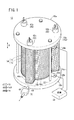
図1及び図2に示すように、本発明の第1の実施形態に係る水電解装置10は、高圧水素製造装置を構成しており、複数の単位セル12が鉛直方向(矢印A方向)に積層された積層体14を備える。積層体14の積層方向一端(上端)には、ターミナルプレート16a、絶縁プレート18a及びエンドプレート20aが上方に向かって、順次、配設される。積層体14の積層方向他端(下端)には、同様にターミナルプレート16b、絶縁プレート18b及びエンドプレート20bが下方に向かって、順次、配設される。
As shown in FIG.1 and FIG.2, the
水電解装置10は、例えば、矢印A方向に延在する複数のタイロッド22を介して円盤形状のエンドプレート20a、20b間を一体的に締め付け保持する。なお、水電解装置10は、エンドプレート20a、20bを端板として含む箱状ケーシング(図示せず)により一体的に保持される構成を採用してもよい。また、水電解装置10は、全体として略円柱体形状を有しているが、立方体形状等の種々の形状に設定可能である。
The
図1に示すように、ターミナルプレート16a、16bの側部には、端子部24a、24bが外方に突出して設けられる。端子部24a、24bは、配線26a、26bを介して電源28に電気的に接続される。陽極(アノード)側である端子部24aは、電源28のプラス極に接続される一方、陰極(カソード)側である端子部24bは、前記電源28のマイナス極に接続される。
As shown in FIG. 1,
図2及び図3に示すように、単位セル12は、略円盤状の電解質膜・電極構造体32と、この電解質膜・電極構造体32を挟持するアノード側セパレータ34及びカソード側セパレータ36とを備える。アノード側セパレータ34及びカソード側セパレータ36は、略円盤状を有するとともに、例えば、カーボン部材等で構成され、又は、鋼板、ステンレス鋼板、チタン板、アルミニウム板、めっき処理鋼板、あるいはその金属表面に防食用の表面処理を施した金属板をプレス成形して、あるいは切削加工した後に防食用の表面処理を施して構成される。
As shown in FIGS. 2 and 3, the
電解質膜・電極構造体32は、例えば、パーフルオロスルホン酸の薄膜に水が含浸された固体高分子電解質膜38と、前記固体高分子電解質膜38の両面に設けられるアノード側給電体40及びカソード側給電体42とを備える。
The electrolyte membrane /
固体高分子電解質膜38の両面には、アノード電極触媒層40a及びカソード電極触媒層42aが形成される。アノード電極触媒層40aは、例えば、Ru(ルテニウム)系触媒を使用する一方、カソード電極触媒層42aは、例えば、白金触媒を使用する。
An anode
単位セル12の外周部には、セパレータ面方向(水平方向)外方に突出する第1突出部44a、第2突出部44b及び第3突出部44cがそれぞれ所定の角度位置に形成される。第1突出部44aには、積層方向である矢印A方向に互いに連通して、水(純水)を供給するための水供給連通孔46が設けられる。
On the outer periphery of the
第2突出部44bには、矢印A方向に互いに連通して、反応により生成された酸素及び使用済みの水を排出するための排出連通孔48が設けられる。第3突出部44cには、積層方向である矢印A方向に互いに連通して、反応により生成された水素を流すための水素連通孔50が設けられる。
The second projecting
水素連通孔50の開口断面積は、水供給連通孔46の開口断面積よりも大きく設定される。水素連通孔50が水滴化された凝縮水により閉塞されることを阻止するためであり、必要に応じて前記水素連通孔50の開口径を設定することができる。
The opening cross-sectional area of the
図3に示すように、アノード側セパレータ34の電解質膜・電極構造体32に向かう面34aには、水供給連通孔46に連通する供給通路52aと、排出連通孔48に連通する排出通路52bとが設けられる。面34aには、供給通路52a及び排出通路52bに連通する第1流路54が設けられる。この第1流路54は、アノード側給電体40の表面積に対応する範囲内に設けられるとともに、複数の流路溝や複数のエンボス等で構成される(図2及び図3参照)。
As shown in FIG. 3, on the
図3に示すように、カソード側セパレータ36の電解質膜・電極構造体32に向かう面36aには、水素連通孔50に連通する排出通路56が設けられる。面36aには、排出通路56に連通する第2流路58が形成される。この第2流路58は、カソード側給電体42の表面積に対応する範囲内に設けられるとともに、複数の流路溝や複数のエンボス等で構成される(図2及び図3参照)。
As shown in FIG. 3, a
アノード側セパレータ34及びカソード側セパレータ36の外周端部を周回して、シール部材60a、60bが一体化される。このシール部材60a、60bには、例えば、EPDM、NBR、フッ素ゴム、シリコーンゴム、フロロシリコーンゴム、ブチルゴム、天然ゴム、スチレンゴム、クロロプレーン又はアクリルゴム等のシール材、クッション材、あるいはパッキン材が用いられる。
The
図1に示すように、エンドプレート20aには、水供給連通孔46、排出連通孔48及び水素連通孔50に連通する配管62a、62b及び62cが接続される。配管62cには、図示しないが、背圧弁(又は電磁弁)が設けられており、水素連通孔50に生成される水素の圧力を高圧に維持することができる。
As shown in FIG. 1,
図2に示すように、水素連通孔50の下部側には、気液分離部を構成する水貯留部64が設けられる。水貯留部64は、エンドプレート20bに形成され、水素連通孔50の下端部に連通して略L字状に屈曲するチャンバ66を備える。チャンバ66には、配水管68が連通するとともに、前記配水管68は、開閉弁70を介して外部に連通する。
As shown in FIG. 2, a
水貯留部64は、この水貯留部64に貯留されている水の水位を検出する上側水位センサ72a及び下側水位センサ72bを備える。上側水位センサ72aは、最下端位置に配置される第2流路58よりも下方に配設される一方、下側水位センサ72bは、チャンバ66の下端位置よりも上方に配置される。
The
このように構成される水電解装置10の動作について、以下に説明する。
The operation of the
図1に示すように、配管62aから水電解装置10の水供給連通孔46に水が供給されるとともに、ターミナルプレート16a、16bの端子部24a、24bに電気的に接続されている電源28を介して電圧が付与される。このため、図3に示すように、各単位セル12では、水供給連通孔46からアノード側セパレータ34の第1流路54に水が供給され、この水がアノード側給電体40内に沿って移動する。
As shown in FIG. 1, water is supplied from a
従って、水は、アノード電極触媒層40aで電気により分解され、水素イオン、電子及び酸素が生成される。この陽極反応により生成された水素イオンは、固体高分子電解質膜38を透過してカソード電極触媒層42a側に移動し、電子と結合して水素が得られる。
Accordingly, water is decomposed by electricity in the anode
このため、カソード側セパレータ36とカソード側給電体42との間に形成される第2流路58に沿って水素が流動する。この水素は、水供給連通孔46よりも高圧に維持されており、水素連通孔50を流れて水電解装置10の外部に取り出し可能となる。一方、第1流路54には、反応により生成した酸素と、使用済みの水とが流動しており、これらが排出連通孔48に沿って水電解装置10の外部に排出される。
For this reason, hydrogen flows along the
この場合、第1の実施形態では、単位セル12の外周部には、セパレータ面方向外方に突出する第3突出部44cが形成されるとともに、前記第3突出部44cには、矢印A方向に互いに連通して水素を流すための水素連通孔が設けられている。このため、第3突出部44cは、水電解装置10の外部に突出しており、前記第3突出部44cは、外部雰囲気に曝されて冷却機能を有することができる(図1参照)。
In this case, in the first embodiment, the outer periphery of the
従って、第3突出部44c内に、矢印A方向に延在して設けられている水素連通孔50は、良好に冷却され、前記水素連通孔50内では、水素中に含まれる水分が結露し、水貯留部64に貯留される。すなわち、水素連通孔50は、気液分離機能を兼用することが可能になる。
Therefore, the
これにより、第1の実施形態では、水電解装置10の外部に別体の気液分離装置を配設する必要がなく、設備用の設置スペースを可及的に狭小に設定することができる。このため、簡単な構成で、水電解により生成された水素中に含まれる水分を確実に除去するとともに、水電解装置10を含む水電解システム全体の小型化を図ることが可能になるという効果が得られる。
Thereby, in 1st Embodiment, it is not necessary to arrange | position a separate gas-liquid separation apparatus outside the
さらに、第1の実施形態では、水素連通孔50の開口断面積は、水供給連通孔46の開口断面積よりも大きく設定されている。従って、水素連通孔50内で結露した水やこの水素連通孔50に排出された水により、該水素連通孔50が閉塞されることを良好に阻止することができる。特に、水素連通孔50の内径を水滴が閉塞し得る径以上の大きさに設定することにより、前記水素連通孔50の閉塞が可及的に阻止される。
Furthermore, in the first embodiment, the opening cross-sectional area of the
また、水貯留部64には、凝縮水を貯留するためのチャンバ66が設けられるとともに、このチャンバ66に連通する配水管68には、開閉弁70が設けられている。このため、開閉弁70の開閉作用下に、チャンバ66に貯留された凝縮水を外部に良好に排出することが可能になる。
The
その際、チャンバ66に貯留される水の最上位置を検出する上側水位センサ72aと、最下位置を検出する下側水位センサ72bとが設けられている。そして、上側水位センサ72aは、最下位置に配置される第2流路58よりも下方に設定されている。これにより、第2流路58から水素連通孔50に排出される水素により、水面の波打による上側水位センサ72aの誤検知を良好に阻止することができる。
At that time, an upper
図4は、本発明の第2の実施形態に係る水電解装置80の一部断面側面図である。
FIG. 4 is a partial cross-sectional side view of a
なお、第1の実施形態に係る水電解装置10と同一の構成要素には同一の参照符号を付して、その詳細な説明は省略する。
In addition, the same referential mark is attached | subjected to the component same as the
水電解装置80は、複数の単位セル12が水平方向(矢印B方向)に積層された積層体14を備える。水電解装置80の下部側(上部側でもよい)には、第3突出部44cが配置され、前記第3突出部44cを介して矢印B方向に沿って水素連通孔50が形成される。
The
エンドプレート20bには、気液分離機能を有する水貯留部82が設けられる。この水貯留部82は、チャンバ66を有するとともに、このチャンバ66の上端が水素連通孔50に連通する。なお、水素連通孔50は、排水性を考慮してエンドプレート20aからエンドプレート20b側に向かって下方に傾斜することが好ましい。
The
このように構成される第2の実施形態では、外部に突出する第3突出部44c内に水素連通孔50が形成されている。このため、水素連通孔50内を良好に冷却して排水性を向上させることができ、前記水素連通孔50が気液分離機能を兼用することが可能になる等、上記の第1の実施形態と同様の効果が得られる。
In the second embodiment configured as described above, the
なお、第1及び第2の実施形態では、第3突出部44cに水素連通孔50が形成されているが、これに加えて、例えば、前記水素連通孔50を周回して冷却水流路(図示せず)を設けることもできる。
In the first and second embodiments, the
また、各単位セル12毎に、第3突出部44cにそれぞれ異なる方向に膨出するフィン部(図示せず)を設けることにより、水素連通孔50の冷却効率を一層向上させることも可能である。
In addition, the cooling efficiency of the hydrogen communication holes 50 can be further improved by providing fin portions (not shown) that bulge in different directions in the third projecting
10、80…水電解装置 12…単位セル
14…積層体 16a、16b…ターミナルプレート
18a、18a…絶縁プレート 20a、20b…エンドプレート
24a、24b…端子部 28…電源
32…電解質膜・電極構造体 34…アノード側セパレータ
36…カソード側セパレータ 38…固体高分子電解質膜
40…アノード側給電体 42…カソード側給電体
44a〜44c…突出部 46…水供給連通孔
48…排出連通孔 50…水素連通孔
54、58…流路 64、82…水貯留部
66…チャンバ 68…配水管
72a、72b…センサ
DESCRIPTION OF
Claims (6)
少なくとも前記セパレータには、前記第1流路の入口側に連通し、前記セパレータの積層方向に沿って延在する水供給連通孔と、
セパレータ面方向外方に突出する突出部と、
が形成されるとともに、
前記突出部には、前記第2流路に連通して前記水素を前記積層方向に流動させ且つ該水素中の水分を結露させる気液分離機能を有する水素連通孔が設けられており、
前記水素連通孔の開口断面積は、前記水供給連通孔の開口断面積よりも大きく設定されることを特徴とする水電解装置。 A power feeding body is provided on both sides of the electrolyte membrane, a separator is stacked on the power feeding body, a first flow path for supplying water is formed between one power feeding body and one separator, and the other A water electrolysis device in which a second flow path for flowing hydrogen obtained by electrolyzing the water is formed between the power supply body of the first electrode and the other separator,
At least the separator communicates with the inlet side of the first flow path, and the water supply communication hole extends along the stacking direction of the separator;
A protruding portion protruding outward in the separator surface direction ;
Is formed,
Wherein the projecting portion is hydrogen passage having a gas-liquid separation function for condensation of moisture and water Motochu in flowing the hydrogen before miracle layer direction communicates is provided in the second flow path,
The opening cross-sectional area of the hydrogen passage is set larger than the opening cross-sectional area of the water supply passage water electrolysis apparatus according to claim Rukoto.
少なくとも前記セパレータには、前記第1流路の入口側に連通し、前記セパレータの積層方向に沿って延在する水供給連通孔と、At least the separator communicates with the inlet side of the first flow path, and the water supply communication hole extends along the stacking direction of the separator;
セパレータ面方向外方に且つ水平方向下部側に突出する突出部と、A protrusion that protrudes outward in the separator surface direction and toward the lower side in the horizontal direction;
が形成されるとともに、Is formed,
前記突出部には、前記第2流路に連通して前記水素を前記セパレータの積層方向に流動させ且つ該水素中の水分を結露させる気液分離機能を有する水素連通孔が設けられており、The protrusion is provided with a hydrogen communication hole having a gas-liquid separation function that communicates with the second flow path to cause the hydrogen to flow in the stacking direction of the separator and to condense moisture in the hydrogen,
前記水素連通孔は、前記一方のセパレータから前記他方のセパレータに向かって下方に傾斜して形成されることを特徴とする水電解装置。The water electrolysis apparatus is characterized in that the hydrogen communication hole is inclined downward from the one separator toward the other separator.
Priority Applications (1)
| Application Number | Priority Date | Filing Date | Title |
|---|---|---|---|
| JP2009033788A JP5349073B2 (en) | 2009-02-17 | 2009-02-17 | Water electrolysis equipment |
Applications Claiming Priority (1)
| Application Number | Priority Date | Filing Date | Title |
|---|---|---|---|
| JP2009033788A JP5349073B2 (en) | 2009-02-17 | 2009-02-17 | Water electrolysis equipment |
Publications (3)
| Publication Number | Publication Date |
|---|---|
| JP2010189689A JP2010189689A (en) | 2010-09-02 |
| JP2010189689A5 JP2010189689A5 (en) | 2012-03-01 |
| JP5349073B2 true JP5349073B2 (en) | 2013-11-20 |
Family
ID=42816036
Family Applications (1)
| Application Number | Title | Priority Date | Filing Date |
|---|---|---|---|
| JP2009033788A Expired - Fee Related JP5349073B2 (en) | 2009-02-17 | 2009-02-17 | Water electrolysis equipment |
Country Status (1)
| Country | Link |
|---|---|
| JP (1) | JP5349073B2 (en) |
Families Citing this family (4)
| Publication number | Priority date | Publication date | Assignee | Title |
|---|---|---|---|---|
| DE102013216587B4 (en) * | 2013-08-21 | 2023-12-28 | Robert Bosch Gmbh | Geometry of a highly efficient media distributor for an electrolysis cell and an electrolysis stack |
| CN111850590A (en) | 2019-04-25 | 2020-10-30 | 上海潓美医疗科技有限公司 | Extended ionic membrane electrolytic cell |
| JP2023144569A (en) | 2022-03-28 | 2023-10-11 | トヨタ自動車株式会社 | Water electrolysis cell, water electrolysis stack |
| JP7148010B1 (en) | 2022-05-02 | 2022-10-05 | トヨタ自動車株式会社 | water electrolysis stack |
Family Cites Families (4)
| Publication number | Priority date | Publication date | Assignee | Title |
|---|---|---|---|---|
| JPS63199888A (en) * | 1987-02-14 | 1988-08-18 | Asahi Glass Co Ltd | Single-electrode electrolytic cell plant |
| JP2001131787A (en) * | 1999-10-29 | 2001-05-15 | Shinko Pantec Co Ltd | Pressure compensation structure of electrolysis cell |
| JP2005213533A (en) * | 2004-01-27 | 2005-08-11 | Matsushita Electric Works Ltd | Hydrogen-producing apparatus |
| JP4847052B2 (en) * | 2005-06-13 | 2011-12-28 | 本田技研工業株式会社 | Gas-liquid separation method and apparatus |
-
2009
- 2009-02-17 JP JP2009033788A patent/JP5349073B2/en not_active Expired - Fee Related
Also Published As
| Publication number | Publication date |
|---|---|
| JP2010189689A (en) | 2010-09-02 |
Similar Documents
| Publication | Publication Date | Title |
|---|---|---|
| JP4796639B2 (en) | Electrochemical equipment | |
| US9269969B2 (en) | Fuel cell stack | |
| US7951284B2 (en) | Electrolysis apparatus, electrochemical reaction membrane apparatus, porous electrical conductor, and production method thereof | |
| JP5048796B2 (en) | Water electrolysis system | |
| JP6270694B2 (en) | Fuel cell stack | |
| JP5349073B2 (en) | Water electrolysis equipment | |
| JP5054049B2 (en) | Electrolyzer | |
| JP4852157B2 (en) | Water electrolysis equipment | |
| JP5400413B2 (en) | Electrolyzer | |
| JP5341547B2 (en) | Water electrolysis system | |
| JP5400414B2 (en) | Electrolyzer | |
| JP4856770B2 (en) | Water electrolysis equipment | |
| JP5415168B2 (en) | Water electrolysis system | |
| JP5421860B2 (en) | Water electrolysis equipment shutdown method | |
| JP5095670B2 (en) | Electrolyzer | |
| JP5415100B2 (en) | Electrolyzer | |
| JP2011208163A (en) | Water electrolyzer | |
| JP5312172B2 (en) | Fuel cell stack | |
| JP5095715B2 (en) | Water electrolysis equipment | |
| JP5350879B2 (en) | Water electrolysis system | |
| JP5095714B2 (en) | Water electrolysis equipment | |
| JP5550961B2 (en) | Fuel cell stack | |
| JP2010251166A (en) | Fuel cell stack | |
| JP5421760B2 (en) | Electrochemical equipment | |
| JP2006092991A (en) | Fuel cell stack |
Legal Events
| Date | Code | Title | Description |
|---|---|---|---|
| A521 | Written amendment |
Free format text: JAPANESE INTERMEDIATE CODE: A523 Effective date: 20120118 |
|
| A621 | Written request for application examination |
Free format text: JAPANESE INTERMEDIATE CODE: A621 Effective date: 20120118 |
|
| A977 | Report on retrieval |
Free format text: JAPANESE INTERMEDIATE CODE: A971007 Effective date: 20121203 |
|
| TRDD | Decision of grant or rejection written | ||
| A01 | Written decision to grant a patent or to grant a registration (utility model) |
Free format text: JAPANESE INTERMEDIATE CODE: A01 Effective date: 20130730 |
|
| A61 | First payment of annual fees (during grant procedure) |
Free format text: JAPANESE INTERMEDIATE CODE: A61 Effective date: 20130820 |
|
| R150 | Certificate of patent or registration of utility model |
Ref document number: 5349073 Country of ref document: JP Free format text: JAPANESE INTERMEDIATE CODE: R150 Free format text: JAPANESE INTERMEDIATE CODE: R150 |
|
| LAPS | Cancellation because of no payment of annual fees |