JP5347192B2 - Drinking water vending machine - Google Patents
Drinking water vending machine Download PDFInfo
- Publication number
- JP5347192B2 JP5347192B2 JP2008200879A JP2008200879A JP5347192B2 JP 5347192 B2 JP5347192 B2 JP 5347192B2 JP 2008200879 A JP2008200879 A JP 2008200879A JP 2008200879 A JP2008200879 A JP 2008200879A JP 5347192 B2 JP5347192 B2 JP 5347192B2
- Authority
- JP
- Japan
- Prior art keywords
- water
- drinking water
- bottle
- nozzle
- vending machine
- Prior art date
- Legal status (The legal status is an assumption and is not a legal conclusion. Google has not performed a legal analysis and makes no representation as to the accuracy of the status listed.)
- Active
Links
Images


Landscapes
- Beverage Vending Machines With Cups, And Gas Or Electricity Vending Machines (AREA)
Abstract
Description
本発明は、水道水を浄水器でミネラル豊富な飲料水に変えて、利用者が飲料水を入れて持ち運び可能で、繰り返し使用できるボトルに供給する飲料水自動販売機に関する。 The present invention relates to a drinking water vending machine that changes tap water into mineral-rich drinking water using a water purifier and supplies the bottle to a bottle that can be carried by the user and can be used repeatedly.
従来の飲料用自動販売機としては、飲料を予めペットボトルやスチール缶、アルミ缶等に入れて販売するものや、自動販売機でカップに飲料を入れて販売するもの(特許文献1参照)など様々なものが用いられている。 Examples of conventional vending machines for beverages include beverages that are sold in plastic bottles, steel cans, aluminum cans, etc., and beverages that are sold in beverage cups (see Patent Document 1). Various things are used.
上述のような自動販売機では、容器はそのまま再利用するものではなく、使い捨てであり、そのままごみとして処分するか、リサイクルして利用する場合もあるが、容器を完全に再利用しているものは無い。
しかしながら、昨今の環境への意識が向上する中、従来の自動販売機のような使い捨ての容器を用いたものは、資源の無駄遣いあるいはCO2排出の点からすると、問題が多いといわざるを得ない。また、最近は環境問題を考えて、マイボトルに飲料水等を入れて持ち歩く人も増えているが、空になったマイボトルに飲料水を供給する方法としては、水道から直接水を入れるか、ペットボトル等で販売されている飲み物を入れるしかない。 However, with the recent increase in awareness of the environment, it has to be said that there are many problems when using disposable containers such as conventional vending machines in terms of waste of resources or CO2 emissions. . In recent years, considering the environmental issues, there are an increasing number of people carrying potable water etc. in my bottles. There is no choice but to put drinks sold in plastic bottles.
そこで、本発明はこのような従来の課題を解決するために、利用者が飲料水を入れて持ち運び可能で、繰り返し使用できるボトルに水道からおいしい飲料水を手軽に供給することができる飲料水用自動販売機を提供することを目的とする。 Therefore, in order to solve such a conventional problem, the present invention is for drinking water in which a user can easily carry delicious water from a water supply into a bottle that can be carried with drinking water and can be used repeatedly. The purpose is to provide vending machines.
本発明の飲料水用自動販売機は、ボトルに飲料水を供給する飲料水用自動販売機であって、水道水を除塵するためのストレーナと、水道水を浄化して飲料水にする浄活水器と、上記浄活水器で浄化された飲料水を冷却する冷却装置と、上記ボトルをセットし、上記冷却水で冷却された飲料水を上記ボトルに供給する給水装置と、水道水を供給する水道、上記ストレーナ、上記浄活水器、上記冷却装置および上記給水装置を接続するフレキシブルホースとを自動販売機本体内部に備え、上記浄活水器は、水道水の水質を還元化する機能性セラミックが内部に充填された活水器と、気化性物を吸着する成形活性炭と微粒子を除去するファインセラミックフィルターが内部に充填された浄水器とから構成され、上記給水装置は、上記ボトルをセットする、前面に開口を設けたボックスと、上記飲料水と上記ボトルを洗浄するための水道水とを吐出するためのノズルと、上記ボトルが所定の位置にセットされているかを確認するためのボトルセンサーとを備えており、上記自動販売機本体前面に、上記ノズルから吐出する洗浄水と飲料水を選択する洗浄用ボタンおよび給水用ボタンと、上記ボトルをセットするボックスの開口を閉じるための扉と、コインセレクターとを設け、上記洗浄用ボタンを押すと、上記水道と上記ノズルを接続するフレキシブルホースに設けられた洗浄電磁弁が作動し、水道水が上記ノズルから吐出され、上記給水用ボタンを押すと、上記冷却装置と上記ノズルとを接続するフレキシブルホースに設けられた給水電磁弁が作動し、飲料水が上記ノズルから吐出されて上記ボトルに飲料水を供給することを特徴とする。 The drinking water vending machine of the present invention is a drinking water vending machine for supplying drinking water to a bottle, and a strainer for removing tap water and purified water for purifying the tap water into drinking water A cooling device that cools drinking water purified by the water purifier, a water supply device that sets the bottle and supplies the drinking water cooled by the cooling water to the bottle, and supplies tap water A water supply, the strainer, the water purifier, the cooling device, and a flexible hose connecting the water supply device are provided inside the vending machine body, and the water purifier is made of a functional ceramic that reduces the quality of tap water. It is composed of a water heater filled inside, a molded activated carbon that adsorbs vaporizable substances, and a water purifier filled with a fine ceramic filter that removes fine particles, and the water supply device sets the bottle A box having an opening in the front, a nozzle for discharging the drinking water and tap water for washing the bottle, and a bottle for checking whether the bottle is set in a predetermined position. A door for closing the opening of the box in which the bottle is set, and a cleaning button and a water supply button for selecting the cleaning water and drinking water discharged from the nozzle, and a front side of the vending machine main body. And a coin selector, and when the washing button is pressed, a washing electromagnetic valve provided on a flexible hose connecting the water supply and the nozzle is activated, and tap water is discharged from the nozzle, and the water supply button is provided. When is pressed, the water supply solenoid valve provided in the flexible hose connecting the cooling device and the nozzle is activated, and the drinking water is discharged from the nozzle. And supplying drinking water to the serial bottle.
上記冷却装置は、冷却用の水を収容する本体と、上記本体の略中央に螺旋状に配置された熱交換器である銅管と、上記銅管を取り囲むように螺旋状に配管された、飲料水が通過するステンレスフレキシブルパイプと、温度センサーとを備え、上記温度センサーによって温度管理を行いながら、上記熱交換器によって上記銅管の周囲の冷却用の水を所定の範囲を冷却して凍らせて氷とし、上記氷によって上記ステンレスフレキシブルパイプを通過する飲料水を冷却する。 The cooling device is a main body that contains water for cooling, a copper pipe that is a heat exchanger arranged in a spiral shape in the approximate center of the main body, and a pipe that is spirally surrounded so as to surround the copper pipe. A stainless flexible pipe through which drinking water passes and a temperature sensor are provided, and while the temperature is controlled by the temperature sensor, cooling water around the copper pipe is cooled to a predetermined range by the heat exchanger and frozen. Let the ice be cooled, and the drinking water passing through the stainless steel flexible pipe is cooled by the ice.
上記冷却装置と上記ノズルとを接続するフレキシブルホースの途中から上記冷却装置へと接続する、パージ電磁弁が取り付けられたフレキシブルホースを設け、上記パージ電磁弁は上記洗浄用ボタンによって作動し、上記洗浄電磁弁が作動している間、上記冷却装置と上記ノズルとを接続するフレキシブルホースに滞留している飲料水を上記冷却装置に冷却用の水として排出する。 A flexible hose with a purge solenoid valve connected to the cooling device from the middle of the flexible hose connecting the cooling device and the nozzle is provided, the purge solenoid valve is operated by the washing button, and the washing While the solenoid valve is operating, the drinking water staying in the flexible hose connecting the cooling device and the nozzle is discharged to the cooling device as cooling water.
上記機能性セラミックは、SiO2:55〜75重量%、Al2O3:7.5〜20重量%およびFe:3〜10重量%を含有すると共にCaとNaとMgとKを合計量で5〜15重量%含有し、上記ファインセラミックフィルターは、SiO2:55〜75重量%、Al2O3:7.5〜20重量%およびFe:3〜10重量%を含有すると共にCaとNaとMgとKを合計量で5〜15重量%含有するセラミック組成物で形成され、表面にSiO2またはAl2O3の表面層を有する。 The functional ceramic, SiO 2: 55 to 75 wt%, Al 2 O 3: 7.5~20 wt% and Fe: a total amount of Ca and Na and Mg and K together contain 3 to 10 wt% The fine ceramic filter contains 5 to 15% by weight, SiO 2 : 55 to 75% by weight, Al 2 O 3 : 7.5 to 20% by weight and Fe: 3 to 10% by weight, and Ca and Na. And a ceramic composition containing Mg to K in a total amount of 5 to 15% by weight, and has a surface layer of SiO 2 or Al 2 O 3 on the surface.
本発明の飲料水用自動販売機は、ボトルに飲料水を供給する飲料水用自動販売機であって、水道水を除塵するためのストレーナと、水道水を浄化して飲料水にする浄活水器と、上記浄活水器で浄化された飲料水を冷却する冷却装置と、上記ボトルをセットし、上記冷却水で冷却された飲料水を上記ボトルに供給する給水装置と、水道水を供給する水道、上記ストレーナ、上記浄活水器、上記冷却装置および上記給水装置を接続するフレキシブルホースとを自動販売機本体内部に備え、上記浄活水器は、水道水の水質を還元化する機能性セラミックが内部に充填された活水器と、気化性物を吸着する成形活性炭と微粒子を除去するファインセラミックフィルターが内部に充填された浄水器とから構成され、上記給水装置は、上記ボトルをセットする、前面に開口を設けたボックスと、上記飲料水と上記ボトルを洗浄するための水道水とを吐出するためのノズルと、上記ボトルが所定の位置にセットされているかを確認するためのボトルセンサーとを備えており、上記自動販売機本体前面に、上記ノズルから吐出する洗浄水と飲料水を選択する洗浄用ボタンおよび給水用ボタンと、上記ボトルをセットするボックスの開口を閉じるための扉と、コインセレクターとを設け、上記洗浄用ボタンを押すと、上記水道と上記ノズルを接続するフレキシブルホースに設けられた洗浄電磁弁が作動し、水道水が上記ノズルから吐出され、上記給水用ボタンを押すと、上記冷却装置と上記ノズルとを接続するフレキシブルホースに設けられた給水電磁弁が作動し、飲料水が上記ノズルから吐出されて上記ボトルに飲料水を供給することにより、利用者が持ってきたボトルに、水道水からミネラル豊富な飲料水を簡単に販売することができる。 The drinking water vending machine of the present invention is a drinking water vending machine for supplying drinking water to a bottle, and a strainer for removing tap water and purified water for purifying the tap water into drinking water A cooling device that cools drinking water purified by the water purifier, a water supply device that sets the bottle and supplies the drinking water cooled by the cooling water to the bottle, and supplies tap water A water supply, the strainer, the water purifier, the cooling device, and a flexible hose connecting the water supply device are provided inside the vending machine body, and the water purifier is made of a functional ceramic that reduces the quality of tap water. It is composed of a water heater filled inside, a molded activated carbon that adsorbs vaporizable substances, and a water purifier filled with a fine ceramic filter that removes fine particles, and the water supply device sets the bottle A box having an opening in the front, a nozzle for discharging the drinking water and tap water for washing the bottle, and a bottle for checking whether the bottle is set in a predetermined position. A door for closing the opening of the box in which the bottle is set, and a cleaning button and a water supply button for selecting the cleaning water and drinking water discharged from the nozzle, and a front side of the vending machine main body. And a coin selector, and when the washing button is pressed, a washing electromagnetic valve provided on a flexible hose connecting the water supply and the nozzle is activated, and tap water is discharged from the nozzle, and the water supply button is provided. When is pressed, the water supply solenoid valve provided in the flexible hose connecting the cooling device and the nozzle is activated, and the drinking water is discharged from the nozzle. By supplying drinking water to the serial bottle, the bottle that the user has brought, it is possible to easily sell the mineral-rich drinking water from the tap water.
上記冷却装置と上記ノズルとを接続するフレキシブルホースの途中から上記冷却装置へと接続する、パージ電磁弁が取り付けられたフレキシブルホースを設け、上記パージ電磁弁は上記洗浄用ボタンによって作動し、上記洗浄電磁弁が作動している間、上記冷却装置と上記ノズルとを接続するフレキシブルホースに滞留している飲料水を上記冷却装置に冷却用の水として排出することにより、冷却装置とノズルの間のフレキシブルホースに滞留した飲料水が温かくなった場合でも、温かい飲料水を排出して、いつも冷却された飲料水をボトルに供給することができる。 A flexible hose with a purge solenoid valve connected to the cooling device from the middle of the flexible hose connecting the cooling device and the nozzle is provided, the purge solenoid valve is operated by the washing button, and the washing While the solenoid valve is operating, the drinking water staying in the flexible hose connecting the cooling device and the nozzle is discharged to the cooling device as cooling water, so Even when the drinking water staying in the flexible hose becomes warm, it is possible to discharge the warm drinking water and supply the bottle with the always cooled drinking water.
上記機能性セラミックは、SiO2:55〜75重量%、Al2O3:7.5〜20重量%およびFe:3〜10重量%を含有すると共にCaとNaとMgとKを合計量で5〜15重量%含有し、上記ファインセラミックフィルターは、SiO2:55〜75重量%、Al2O3:7.5〜20重量%およびFe:3〜10重量%を含有すると共にCaとNaとMgとKを合計量で5〜15重量%含有するセラミック組成物で形成され、表面にSiO2またはAl2O3の表面層を有することにより、水道水からミネラル豊富でまろやかな飲料水を供給することができる。 The functional ceramic, SiO 2: 55 to 75 wt%, Al 2 O 3: 7.5~20 wt% and Fe: a total amount of Ca and Na and Mg and K together contain 3 to 10 wt% The fine ceramic filter contains 5 to 15% by weight, SiO 2 : 55 to 75% by weight, Al 2 O 3 : 7.5 to 20% by weight and Fe: 3 to 10% by weight, and Ca and Na. It is made of a ceramic composition containing 5 to 15% by weight of Mg and K in a total amount, and has a surface layer of SiO 2 or Al 2 O 3 on the surface, so that it is possible to provide mineral-rich mellow drinking water from tap water Can be supplied.
本発明の飲料水用自動販売機について図面を用いて以下に詳細に説明する。図1に示すのが本発明の飲料水用自動販売機1の外観であり、図2に示すのが飲料水用自動販売機1の概略内部構造である。ここでは、利用者が飲料水を入れて持ち運び可能で、繰り返し使用できるボトルとしてステンレスボトル10を用いて説明するが、ステンレスボトルに限定するものではなく、例えば、陶器のボトル等も使用可能である。
The drinking water vending machine of the present invention will be described in detail below with reference to the drawings. FIG. 1 shows the appearance of the drinking water vending machine 1 of the present invention, and FIG. 2 shows the schematic internal structure of the drinking water vending machine 1. Here, the description will be made using the
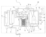
図2に示すように、本発明の飲料水用自動販売機1は、本体20の内部に、水道水を除塵するためのストレーナ5と、水道水を浄化して飲料水にする浄活水器と、上記浄活水器で浄化された飲料水を冷却する冷却装置4と、上記ステンレスボトル10をセットし、上記冷却装置4で冷却された飲料水を上記ステンレスボトル10に供給する給水装置6と、水道7、上記ストレーナ5、上記浄活水器、上記冷却装置4および上記給水装置6等を接続するフレキシブルホース8とを備える。
As shown in FIG. 2, the drinking water vending machine 1 according to the present invention includes a
上記浄活水器は、水道水の水質を還元化する機能性セラミック28を内蔵する活水器2と、気化性物を吸着する成形活性炭29と微粒子を除去するファインセラミックフィルター30を内蔵する浄水器3とから構成される。
The above water purifier includes a
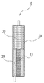
上記活水器2は、図3に示すように、外筒31と内筒32から構成され、上記外筒31と上記内筒32には上記機能性セラミック28が充填されている。そして、上記ストレーナ5を通ってきた水は、上記外筒31に充填された機能性セラミック28から上気内筒32に充填された機能性セラミック28を通過し、還元質傾向になり水素イオン豊富な飲料水に変換される。
As shown in FIG. 3, the
上記機能性セラミック28は、SiO2:55〜75重量%、Al2O3:7.5〜20重量%およびFe:3〜10重量%を含有すると共にCaとNaとMgとKを合計量で5〜15重量%含有するセラミック組成物で形成されたものである。上記機能性セラミック28は均質に一体成形しても良いが、少なくとも表面がこのようなセラミックで形成されていればよいので、高温に耐える種々の基材の表面に釉薬(上薬)を塗布し、これを焼成することによって少なくとも表面を所定のセラミックで形成することができる。 The functional ceramic 28, SiO 2: 55 to 75 wt%, Al 2 O 3: 7.5~20 wt% and Fe: total amount of Ca and Na and Mg and K together contain 3 to 10 wt% And is formed of a ceramic composition containing 5 to 15% by weight. The functional ceramic 28 may be integrally formed integrally. However, since at least the surface of the functional ceramic 28 only needs to be formed of such a ceramic, a glaze (supplement) is applied to the surfaces of various substrates that can withstand high temperatures. By firing this, at least the surface can be formed of a predetermined ceramic.
このようなセラミック組成物の例として、具体的には花崗岩を主成分とするものを採用できる。花崗岩の組成は、例えばNa2O:1.0〜2.5重量%、MgO:1.0〜2.5重量%、Al2O3:13〜20重量%、SiO2:55〜70重量%、SO3:1.0〜2.0重量%、K2O:3〜4重量%、CaO:2〜4重量%、TiO2:0.5〜1.2重量%およびFe2O3:7〜15重量%である。 As an example of such a ceramic composition, specifically, a composition mainly composed of granite can be adopted. The composition of granite is, for example, Na 2 O: 1.0 to 2.5 wt%, MgO: 1.0 to 2.5 wt%, Al 2 O 3 : 13 to 20 wt%, SiO 2 : 55 to 70 wt%. %, SO 3: 1.0 to 2.0 wt%, K 2 O: 3~4 wt%, CaO: 2 to 4 wt%, TiO 2: 0.5 to 1.2 wt% and Fe 2 O 3 : 7 to 15% by weight.
上記機能性セラミック28として、粒状セラミック材を用いる場合、例えば直径3〜12mm程度の球状粒に形成したものを採用できる。また、無機質の発泡体や焼結体を基材として用いる場合は、通気孔0.1nm〜100nm程度の連通気孔を有する多孔質材であることが好ましい。 In the case where a granular ceramic material is used as the functional ceramic 28, for example, one formed in a spherical particle having a diameter of about 3 to 12 mm can be employed. Moreover, when using an inorganic foam and a sintered compact as a base material, it is preferable that it is a porous material which has a continuous ventilation hole about 0.1-100 nm of ventilation holes.
また、上記機能性セラミック28として、ミネラル抽出用セラミック材を管の内部に設けた格子の表面に釉薬として被覆し、焼成することによって、格子状セラミック材その他のハニカム状セラミック材などに形成することもできる。格子の間隔や孔径は、例えば0.5〜2mmにすると水との接触効率がよくて好ましい。 Further, as the functional ceramic 28, a ceramic material for mineral extraction is coated as a glaze on the surface of the lattice provided inside the tube and fired to form a lattice-shaped ceramic material or other honeycomb-shaped ceramic material. You can also. For example, the lattice spacing and the hole diameter are preferably 0.5 to 2 mm because of good contact efficiency with water.
また、釉薬として、Na、Mg、Al、Si、S、K、Ca、TiおよびFeを主成分として酸化物換算で95重量%以上含有する鉱物微粉100重量部、リン化チタン(TiP)1〜4重量部、酸化マンガン3〜5重量部および磁鉄鉱1〜2重量部を含んでいるセラミック組成物を採用することができる。 Further, as glaze, 100 parts by weight of fine mineral powder containing Na, Mg, Al, Si, S, K, Ca, Ti and Fe as main components and containing 95% by weight or more in terms of oxide, titanium phosphide (TiP) 1 to A ceramic composition containing 4 parts by weight, 3-5 parts by weight manganese oxide and 1-2 parts by weight magnetite can be employed.
上記浄水器3は、図4に示すように、外筒31の下段に5μm以下の微粒子を吸着除去できるような微細な気孔を有する成形活性炭29が充填され、上段に微粒子を除去するファインセラミックフィルター30が充填されている。さらに、下段に充填された成形活性炭29の中央にはセラミックの充填材33が配置されている。上記浄水器3に送られた水は、初めに下段の成形活性炭29を通過し、さらに中央のセラミックの充填材を通過して、遊離塩素等の気化物質が除去され、次に上段のファインセラミックフィルター30を通過してダイオキシンや金属質等の粒径が100nm以上の微粒子が除去される。これにより、水本来のミネラルを活かし、余分なものを取除くことでおいしい飲料水を供給することができる。
As shown in FIG. 4, the
上記浄水器3に充填された上記ファインセラミックフィルター30は、セラミックの多孔体からなる基材の表面または中間層に、フィルタの濾過性能を決定する気孔径の分離層を形成したものであり、SiO2:55〜75重量%、Al2O3:7.5〜20重量%およびFe:3〜10重量%を含有すると共に、CaとNaとMgとKを合計量で5〜15重量%含有するセラミック組成物で基材を形成し、表面層をSiO2またはAl2O3で形成し、粒径が100nm以上の高分子、微生物、金属微粒子をも分離し、粒径が0.1nm〜20nm程度のイオン化されたミネラルを通過させるものを採用することが好ましい。
The fine
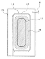
上記給水装置6は、上記ステンレスボトル10をセットする、前面に開口を設けたボックス21と、上記ボックス21の上面に設けられた、飲料水と上記ステンレスボトル10を洗浄するための水道水とを吐出するためのノズル9と、上記ボックス21の背面に設けられた、上記ステンレスボトル10が所定の位置にセットされているかを確認するためのボトルセンサー16とを備える。
The
上記給水装置6は、さらに、上記ステンレスボトル10を所定の位置にセットするために凹部を設けた受け台22と、排水用に上記受け台22の下部に設けられた排水トレイ23を備える。上記受け台22の凹部は上記ステンレスボトル10の底面がほぼ収まる大きさ(Φ70mmの円形)に形成され、所定の大きさよりも大きいボトルはセットできないようにされている。
The
上記ボトルセンサー16を上記ステンレスボトル10の背面と正面の下の方に位置するように上記給水装置6に設け、上記ボトルセンサー16の表面から1mm以内に上記ステンレスボトル10が存在するかどうかを検出するように設定し、背面と正面に設けられた2個のボトルセンサー16で同時に上記ステンレスボトル10が検出されると、所定の大きさのステンレスボトル10がセットされていると判断する。
The
そして、Φ68mm未満のボトルが受け台22にセットされている場合には、背面と正面に設けられた2個のボトルセンサー16は、1個だけがボトルを検出する、あるいは前後に配置された上記ボトルセンサー16のどちらもボトルを検出しないので、この時には、ボトルの大きさが小さいと判断し、飲料水の供給は行われない。
And when the bottle below (PHI) 68mm is set in the receiving
上記本体20の前面には、図1に示すように、上記ノズル9から洗浄水と飲料水を吐出させるためのボタン17,18,19と、上記ボックス21を閉じるための扉24と、コインセレクター27とを設ける。上記ボタン17,18,19は、上から順に洗浄用ボタン17、給水用ボタン(500ml)18、給水用ボタン(350ml)19となっており、洗浄用ボタン17を押すと、洗浄用の水道水が供給され、給水用ボタン18,19を押すと、ボタンに応じた量(350mlあるいは500ml)の飲料水が供給される。
On the front surface of the
上記冷却装置4は、冷却用の水が入れられた本体25と、上記本体25の略中央に螺旋状に配置された熱交換器である銅管15と、上記銅管15を取り囲むように螺旋状に配管された、飲料水が通過するステンレスフレキシブルパイプ14と、温度センサー26とを備える。
The cooling device 4 includes a
上記冷却装置4は、図5に示すように、上記銅管15によってその周囲の冷却用の水が氷34となり、その氷34の周囲を上記ステンレスフレキシブルパイプ14を飲料水が通過して冷却される構造であり、上記氷34が大きくなると上記ステンレスレスフレキシブルパイプ14を通過する飲料水が凍ってしまうので、氷34が大きくならないように、上記銅管15と上記ステンレスフレキシブルパイプ14の間に温度センサー26を設けている。
As shown in FIG. 5, in the cooling device 4, the cooling water around the
上記温度センサー26によって温度管理を行い、上記温度センサー26によって水温が0℃以下になるのを感知すると、上記銅管15による冷却を停止し、氷34が大きくなるのを防止する。また、上記温度センサー26によって水温が0℃以上になるのを感知すると上記銅管15による冷却を開始する。このようにして、上記銅管15の周囲の水を所定の範囲冷却し凍らせて氷34を適切な状態に保つ。
When the temperature control is performed by the
水道7、上記ストレーナ5、上記浄活水器、上記冷却装置4および上記給水装置6等を接続するフレキシブルホース8には複数の電磁弁11,12,13を設けている。上記ノズル9と上記冷却装置4を接続するフレキシブルホース8の途中には給水電磁弁11が設けている。そして、上記給水電磁弁11と上記ノズル9とを接続するフレキシブルホース8の途中から枝分かれし、水道へと接続されるフレキシブルホース8の途中には洗浄電磁弁12が設けている。さらに、上記冷却装置4と上記給水電磁弁11とを接続するフレキシブルホース8の途中から枝分かれし、上記冷却装置4の本体25へと接続されるフレキシブルホース8の途中にパージ電磁弁13が設けている。
A plurality of
上記電磁弁11,12,13は上記ボタン17,18,19と連動して作動する。上記洗浄用ボタン17を押すと、上記洗浄電磁弁12が作動し、水道水が上記ノズル9から吐出されて上記ステンレスボトル10を洗浄する。この時、上記給水電磁弁11は停止しているが、上記パージ電磁弁13は作動して、上記冷却装置4と上記給水電磁弁11を接続するフレキシブルホース8内に滞留した飲料水を上記冷却装置に排出する。これは、上記冷却装置4と上記給水電磁弁11を接続するフレキシブルホース8内に滞留した飲料水は時間と共に水温が上昇するために、温かくなった飲料水を供給しないようにするためである。
The
そして、上記給水用ボタン18,19を押すと、上記給水電磁弁11が作動し、選択された供給量に応じて飲料水が上記ノズル9から吐出されて上記ステンレスボトル10に所定量の飲料水が供給される。この時の供給量を制御するためにパルス制御流量計35を上記冷却装置4と上記給水電磁弁11の間に設けている。なお、給水前には必ず洗浄を行うように、上記給水用ボタン18,19は、上記洗浄用ボタン17を作動していなければ、作動しない構造としている。
When the
本発明の飲料水用自動販売機1における水道水を飲料水に処理する機構について説明する。まず初めに、水道7から水道水が供給され、上記フレキシブルホース8を通ってストレーナ5に送られる。上記ストレーナ5によって水道水の塵を取除く。
A mechanism for processing tap water into drinking water in the drinking water vending machine 1 of the present invention will be described. First, tap water is supplied from the water supply 7 and sent to the
次に、上記活水器2へと送られた水道水は、上記機能性セラミック28によって水質が還元化され、さらにフレキシブルホース8を経て上記浄水器3へ送られ、下段の上記成形活性炭29によって遊離塩素等の気化物質が吸着され、上段の上記ファインセラミックフィルター30によって、細菌、重金属、高分子等の100nm以上の微粒子が除去され、粒径が0.1nm〜20nm程度のイオン化されたミネラルを含んだ飲料水となる。さらに、上記冷却装置4へと送られ、約2〜3℃に冷却され、冷たくておいしい飲料水を供給することができる状態となる。
Next, the tap water sent to the
このようにして得られる飲料水は、天然のミネラルバランスを有するものとなり、還元質傾向のまろやかで、遊離塩素や有機物が少ない、ミネラル豊富な非常においしい水となる。そして、水質の分析を行うと日本名水百選と同レベルの水質であることがわかっている。このように、本発明の飲料水用自動販売機1を用いると簡単に水道水からミネラル豊富な冷たくておいしい飲料水を供給することができる。 The drinking water obtained in this way has a natural mineral balance, and is a very delicious water rich in minerals with a mild tendency of reducing quality and low free chlorine and organic matter. And when the water quality is analyzed, it is known that the water quality is the same level as the 100 best waters in Japan. As described above, when the drinking water vending machine 1 according to the present invention is used, cold and delicious drinking water rich in minerals can be easily supplied from tap water.
上記飲料水用自動販売機の使用方法について詳しく説明する。まず初めに、利用者が上記コインセレクター27に所定の料金を投入すると、上記扉24のロックが解除される。利用者は上記扉24を開けて、ステンレスボトルを受け台22の凹部にセットし、上記扉24を閉める。この時、ボトルセンサー16によって、所定のステンレスボトル10が所定の位置にセットされているかどうかを確認し、問題が無ければ上記扉24がロックされ、上記洗浄用ボタン17が点滅する。
A method of using the drinking water vending machine will be described in detail. First, when the user inserts a predetermined fee into the
利用者は上記洗浄用ボタン17の点滅を確認したら上記洗浄用ボタン17を押す。上記洗浄用ボタン17が押されると、上記洗浄電磁弁12が作動し、水道水が上記ノズル9から上記ステンレスボトル10に吐出される。上記ノズル9からの吐出が終わると利用者は上記扉24を開けて上記ステンレスボトルを洗浄し、上記排水トレイ23に洗浄した水を排水する。上記洗浄用ボタン17が押されると、上記パージ電磁弁13も作動し、上記冷却装置4と上記給水電磁弁11を接続するフレキシブルホース8内に滞留している飲料水を上記冷却装置4に排出する。
When the user confirms that the
洗浄が終わったら再度、上記ステンレスボトル10を所定の位置にセットし、扉24を閉じる。そして、利用者は必要な飲料水の量に応じて、上記給水用ボタン18,19を選択して押すと、上記給水電磁弁11が作動し上記ノズル9から飲料水がステンレスボトル10に供給される。そして、選択され飲料水の量に応じて、パルス制御流量計35が作動し、上記給水電磁弁11を作動させて飲料水の供給を停止する。飲料水の供給が停止したら利用者はステンレスボトル10を取り出して蓋を閉めると、飲料水の購入が完了する。
When the cleaning is completed, the
このように、本発明の飲料水用自動販売機は、繰り返し使用可能なステンレスボトルに飲料水を供給することで、従来の自動販売機で飲料水を販売する場合と比較すると、より簡単に、より安価に、よりおいしい水を販売することが可能となる。 Thus, the drinking water vending machine of the present invention is easier to supply drinking water to stainless steel bottles that can be used repeatedly, compared to selling drinking water with conventional vending machines, It becomes possible to sell more delicious water at a lower price.
また、環境問題の観点から考えても、より優れた効果を有することを以下に説明する。CO2排出量を従来の自動販売機で、飲料水の容器としてスチール缶、アルミ缶、ペットボトル、紙コップを用いて飲料水を販売したケースと本発明のステンレスボトルを用いた飲料水用自動販売機とを比較してみる。 In addition, it will be described below that it has a more excellent effect from the viewpoint of environmental problems. A vending machine that sells drinking water using steel cans, aluminum cans, plastic bottles, and paper cups as drinking water containers and vending machines for drinking water using the stainless steel bottles of the present invention. Compare with the machine.
各ケースについて、CO2排出量を、製造(容器、飲料水、自動販売機の装置の製造)、輸送1(容器と飲料水の輸送)、利用(自動販売機の稼動に必要な電力)、洗浄(本発明の飲料水用自動販売機のみ)、輸送2(容器の回収に関する輸送)、リサイクル追加行程(リサイクル処理)、リサイクル効果(リサイクルによるCO2削減効果)、輸送(容器の焼却・廃棄に必要な輸送)、焼却・埋立(容器の焼却処理、容器の廃棄に伴う埋立処理)の項目毎に算出し、各ケース合計して、飲料水1ml当りのCO2排出量を求める。CO2排出量(t−C/ml)を表にしたのが以下の表1である。 For each case, CO2 emissions are produced (manufacture of containers, drinking water, vending machine equipment), transport 1 (transport of containers and drinking water), use (electric power required for vending machine operation), washing (Only for vending machines for drinking water of the present invention), transport 2 (transport related to container recovery), additional recycling process (recycling process), recycling effect (CO2 reduction effect due to recycling), transport (necessary for incineration and disposal of containers) Calculation) and incineration / landfill (container incineration, landfill treatment associated with container disposal), and sum up each case to obtain the CO2 emission per ml of drinking water. Table 1 below shows the CO2 emission (t-C / ml).

そして、得られた結果をグラフにしたのが図6である。本発明の飲料水用自動販売機のCO2は4.42×10⁻⁸(t−C/ml)であり、最もCO2排出量が少ないことがわかる。紙コップ(2.69×10−7(t−C/ml))と較べると約1/6となり、従来のケースで最も少ないペットボトル(8.15×10−8(t−C/ml))と比較しても約4割減となっており、ステンレスボトルを用いた本発明のCO2削減効果が大きいことがよくわかる。 FIG. 6 is a graph showing the obtained results. CO2 of the vending machine for drinking water of the present invention is 4.42 × 10 −8 (tC / ml), and it can be seen that the amount of CO2 emission is the smallest. Compared with paper cups (2.69 × 10 −7 (tC / ml)), it is about 1/6, the smallest PET bottle in the conventional case (8.15 × 10 −8 (tC / ml)) ), The CO2 reduction effect of the present invention using a stainless bottle is large.
このように、本発明の飲料水用自動販売機は、おいしい水を簡単に供給できるだけではなく、CO2削減にも大きな効果を有している。 Thus, the drinking water vending machine of the present invention can not only supply delicious water easily, but also has a great effect on CO2 reduction.
1 飲料水用自動販売機
2 活水器
3 浄水器
4 冷却装置
5 ストレーナ
6 給水装置
7 水道
8 フレキシブルホース
9 ノズル
10 ステンレスボトル
11 給水電磁弁
12 洗浄電磁弁
13 パージ電磁弁
14 ステンレスフレキシブルパイプ
15 銅管
16 ボトルセンサー
17 洗浄用ボタン
18 給水用ボタン
19 給水用ボタン
20 自動販売機本体
21 ボックス
22 受け台
23 排水トレイ
24 扉
25 本体
26 温度センサー
27 コインセレクター
28 機能性セラミック
29 成形活性炭
30 ファインセラミックフィルター
31 外筒
32 内筒
33 充填材
34 氷
35 パルス流量計
DESCRIPTION OF SYMBOLS 1 Drinking
Claims (3)
水道水を除塵するためのストレーナと、
水道水を浄化して飲料水にする浄活水器と、
上記浄活水器で浄化された飲料水を冷却する冷却装置と、
上記ボトルをセットし、上記冷却水で冷却された飲料水を上記ボトルに供給する給水装置と、
水道水を供給する水道、上記ストレーナ、上記浄活水器、上記冷却装置および上記給水装置を接続するフレキシブルホースとを自動販売機本体内部に備え、
上記浄活水器は、水道水の水質を還元化する機能性セラミックが内部に充填された活水器と、気化性物を吸着する成形活性炭と微粒子を除去するファインセラミックフィルターが内部に充填された浄水器とから構成され、
上記給水装置は、上記ボトルをセットする、前面に開口を設けたボックスと、上記飲料水と上記ボトルを洗浄するための水道水とを吐出するためのノズルと、上記ボトルが所定の位置にセットされているかを確認するためのボトルセンサーとを備えており、
上記自動販売機本体前面に、上記ノズルから吐出する洗浄水と飲料水を選択する洗浄用ボタンおよび給水用ボタンと、上記ボトルをセットするボックスの開口を閉じるための扉と、コインセレクターとを設け、上記洗浄用ボタンを押すと、上記水道と上記ノズルを接続するフレキシブルホースに設けられた洗浄電磁弁が作動し、水道水が上記ノズルから吐出され、上記給水用ボタンを押すと、上記冷却装置と上記ノズルとを接続するフレキシブルホースに設けられた給水電磁弁が作動し、飲料水が上記ノズルから吐出されて上記ボトルに飲料水を供給し、
上記冷却装置と上記ノズルとを接続するフレキシブルホースの途中から上記冷却装置へと接続する、パージ電磁弁が取り付けられたフレキシブルホースを設け、上記パージ電磁弁は上記洗浄用ボタンによって作動し、上記洗浄電磁弁が作動している間、上記冷却装置と上記ノズルとを接続するフレキシブルホースに滞留している飲料水を上記冷却装置に冷却用の水として排出することを特徴とする飲料水用自動販売機。 A vending machine for drinking water that allows users to carry drinking water and carry it to bottles that can be used repeatedly,
A strainer for removing tap water,
A water purifier that purifies tap water and makes it drinking water,
A cooling device for cooling the drinking water purified by the water purifier,
A water supply device for setting the bottle and supplying drinking water cooled by the cooling water to the bottle;
A water supply for supplying tap water, the strainer, the water purifier, the cooling device, and a flexible hose connecting the water supply device are provided inside the vending machine body,
The above-mentioned water purifier is a water purifier filled with a functional ceramic that reduces the quality of tap water, a molded activated carbon that adsorbs vaporizable substances, and a fine ceramic filter that removes fine particles. And consists of
The water supply device sets the bottle, a box having an opening on the front surface, a nozzle for discharging the drinking water and tap water for washing the bottle, and the bottle is set at a predetermined position. With a bottle sensor to check if
Provided on the front surface of the vending machine body are a washing button and a water supply button for selecting washing water and drinking water discharged from the nozzle, a door for closing the opening of the box for setting the bottle, and a coin selector. When the washing button is pressed, a washing electromagnetic valve provided in a flexible hose connecting the water supply and the nozzle is operated, tap water is discharged from the nozzle, and when the water supply button is pressed, the cooling device And a water supply solenoid valve provided on a flexible hose connecting the nozzle and the drinking water is operated, drinking water is discharged from the nozzle to supply drinking water to the bottle ,
A flexible hose with a purge solenoid valve connected to the cooling device from the middle of the flexible hose connecting the cooling device and the nozzle is provided, the purge solenoid valve is operated by the washing button, and the washing Drinking water vending machine that discharges drinking water staying in a flexible hose connecting the cooling device and the nozzle to the cooling device as cooling water while the solenoid valve is operating Machine.
Priority Applications (1)
| Application Number | Priority Date | Filing Date | Title |
|---|---|---|---|
| JP2008200879A JP5347192B2 (en) | 2008-08-04 | 2008-08-04 | Drinking water vending machine |
Applications Claiming Priority (1)
| Application Number | Priority Date | Filing Date | Title |
|---|---|---|---|
| JP2008200879A JP5347192B2 (en) | 2008-08-04 | 2008-08-04 | Drinking water vending machine |
Publications (2)
| Publication Number | Publication Date |
|---|---|
| JP2010039699A JP2010039699A (en) | 2010-02-18 |
| JP5347192B2 true JP5347192B2 (en) | 2013-11-20 |
Family
ID=42012194
Family Applications (1)
| Application Number | Title | Priority Date | Filing Date |
|---|---|---|---|
| JP2008200879A Active JP5347192B2 (en) | 2008-08-04 | 2008-08-04 | Drinking water vending machine |
Country Status (1)
| Country | Link |
|---|---|
| JP (1) | JP5347192B2 (en) |
Family Cites Families (5)
| Publication number | Priority date | Publication date | Assignee | Title |
|---|---|---|---|---|
| JP2935347B2 (en) * | 1996-07-26 | 1999-08-16 | 協業組合オー・ド・ヴィ | Bringing container cleaning and sterilizing equipment in mineral water vending equipment |
| JP3043724U (en) * | 1997-05-23 | 1997-11-28 | 征二 奥田 | Production plant and vending machine for purified water or mineral water |
| JP2004042996A (en) * | 2002-07-15 | 2004-02-12 | Hoshizaki Electric Co Ltd | Cold beverage supplying device |
| JP2005100073A (en) * | 2003-09-25 | 2005-04-14 | Koichi Sano | Public water system based online mineral water vending machine |
| JP2005115879A (en) * | 2003-10-06 | 2005-04-28 | Hama Reiki Kogyo Kk | Water producing and selling device |
-
2008
- 2008-08-04 JP JP2008200879A patent/JP5347192B2/en active Active
Also Published As
| Publication number | Publication date |
|---|---|
| JP2010039699A (en) | 2010-02-18 |
Similar Documents
| Publication | Publication Date | Title |
|---|---|---|
| US11731884B2 (en) | Water purifier filter, and water purifier comprising same | |
| CN101218010B (en) | Water purification system | |
| US4948499A (en) | Simplified method and apparatus for purification | |
| US4828692A (en) | Simplified method and apparatus for purification | |
| US8133400B2 (en) | Portable ozonation apparatus for storing and purifying liquid | |
| WO2011037605A2 (en) | Water bottle with filter | |
| KR102304266B1 (en) | filter for water purifier and water purifier using thereof | |
| WO2006004348A1 (en) | Container for reducing alkaline water | |
| US20110186496A1 (en) | Appliances for the alkalizing of water | |
| US20150014252A1 (en) | Water bottle coupled with filtration device | |
| JP3174445U (en) | Water server | |
| JP5347192B2 (en) | Drinking water vending machine | |
| JP3170887U (en) | Water server | |
| KR101074523B1 (en) | A hot and cold water spring manufacture equipment which has air purity and advertisement function | |
| JP2010188331A (en) | Mineral hydrogenated water server tank system | |
| CN103880116A (en) | Water filter kettle with replaceable filter element | |
| JP2004321982A (en) | Hydrogen water generator | |
| RU2264990C1 (en) | Portable device for water purification | |
| CN203079783U (en) | Water filter kettle with sterilizing function | |
| CN207084634U (en) | Filtering cup | |
| CN207671811U (en) | Vapour-pressure type filtration device structure | |
| JP3138526U (en) | Water storage water reformer combined with water storage type water dispenser | |
| KR200178032Y1 (en) | A bottle water filter | |
| CN207726835U (en) | A kind of Portable active energy water machine | |
| CN206970347U (en) | A kind of filter element of water purifier that can adjust temperature |
Legal Events
| Date | Code | Title | Description |
|---|---|---|---|
| A621 | Written request for application examination |
Free format text: JAPANESE INTERMEDIATE CODE: A621 Effective date: 20110801 |
|
| A521 | Request for written amendment filed |
Free format text: JAPANESE INTERMEDIATE CODE: A523 Effective date: 20120801 |
|
| A977 | Report on retrieval |
Free format text: JAPANESE INTERMEDIATE CODE: A971007 Effective date: 20130313 |
|
| A131 | Notification of reasons for refusal |
Free format text: JAPANESE INTERMEDIATE CODE: A131 Effective date: 20130409 |
|
| A521 | Request for written amendment filed |
Free format text: JAPANESE INTERMEDIATE CODE: A523 Effective date: 20130523 |
|
| TRDD | Decision of grant or rejection written | ||
| A01 | Written decision to grant a patent or to grant a registration (utility model) |
Free format text: JAPANESE INTERMEDIATE CODE: A01 Effective date: 20130618 |
|
| A61 | First payment of annual fees (during grant procedure) |
Free format text: JAPANESE INTERMEDIATE CODE: A61 Effective date: 20130627 |
|
| A61 | First payment of annual fees (during grant procedure) |
Free format text: JAPANESE INTERMEDIATE CODE: A61 Effective date: 20130802 |
|
| R150 | Certificate of patent or registration of utility model |
Ref document number: 5347192 Country of ref document: JP Free format text: JAPANESE INTERMEDIATE CODE: R150 Free format text: JAPANESE INTERMEDIATE CODE: R150 |
|
| R250 | Receipt of annual fees |
Free format text: JAPANESE INTERMEDIATE CODE: R250 |
|
| R250 | Receipt of annual fees |
Free format text: JAPANESE INTERMEDIATE CODE: R250 |
|
| R250 | Receipt of annual fees |
Free format text: JAPANESE INTERMEDIATE CODE: R250 |
|
| R250 | Receipt of annual fees |
Free format text: JAPANESE INTERMEDIATE CODE: R250 |
|
| R250 | Receipt of annual fees |
Free format text: JAPANESE INTERMEDIATE CODE: R250 |
|
| R250 | Receipt of annual fees |
Free format text: JAPANESE INTERMEDIATE CODE: R250 |
|
| R250 | Receipt of annual fees |
Free format text: JAPANESE INTERMEDIATE CODE: R250 |
|
| R250 | Receipt of annual fees |
Free format text: JAPANESE INTERMEDIATE CODE: R250 |