JP5346217B2 - Multi-axis robot and its speed control device - Google Patents
Multi-axis robot and its speed control device Download PDFInfo
- Publication number
- JP5346217B2 JP5346217B2 JP2009010549A JP2009010549A JP5346217B2 JP 5346217 B2 JP5346217 B2 JP 5346217B2 JP 2009010549 A JP2009010549 A JP 2009010549A JP 2009010549 A JP2009010549 A JP 2009010549A JP 5346217 B2 JP5346217 B2 JP 5346217B2
- Authority
- JP
- Japan
- Prior art keywords
- axis
- rotation axis
- tool
- robot
- speed
- Prior art date
- Legal status (The legal status is an assumption and is not a legal conclusion. Google has not performed a legal analysis and makes no representation as to the accuracy of the status listed.)
- Active
Links
Images
Abstract
Description
本発明は各種作業用のツール部材を取り付けてなる多軸ロボットに関し、より詳しくは、表面部位の移動速度を所定速度以下に規制するよう動作する多軸ロボット及びその速度制御装置に関する。 The present invention relates to a multi-axis robot to which tool members for various operations are attached, and more particularly to a multi-axis robot that operates so as to regulate the moving speed of a surface portion to a predetermined speed or less and a speed control device thereof.
多軸ロボットは、例えば搬送作業、塗装作業又は溶接作業等の自動化のため、生産分野において広く利用され、その先端部位には各種作業用のツール部材が取り付けられる。多軸ロボットは各回転軸周りの回転を互いに独立して行い得るよう構成され、各回転軸の回転位置の制御によりツール部材を所望位置に所望姿勢で停止させ、各回転軸の角速度の制御によりツール部材を所望経路に沿って所望速度で移動させることができる。 The multi-axis robot is widely used in the production field for automation of, for example, a transfer operation, a painting operation, or a welding operation, and a tool member for various operations is attached to a tip portion thereof. The multi-axis robot is configured to be able to rotate around each rotation axis independently of each other. By controlling the rotation position of each rotation axis, the tool member is stopped at a desired position in a desired posture, and by controlling the angular velocity of each rotation axis. The tool member can be moved along the desired path at a desired speed.
多軸ロボットには多様な動作モード、例えばティーチモード、チェックモード及びリピートモード等がある。ティーチモードは移動開始位置及び移動終了位置を制御装置側に教示するための動作モードであり、このモードではロボットをマニュアル操作により動作させる。チェックモードは、ティーチモードで教示した位置間の移動が適正に行われ得るか否かをチェックするための動作モードであり、これら位置間の移動を予め定めた動作計画に従って自動的に行わせる。リピートモードは、チェックを終了して実用に供する際に使用される動作モードであり、このモードではロボットを自動的且つ継続的に動作させる。 The multi-axis robot has various operation modes such as a teach mode, a check mode, and a repeat mode. The teach mode is an operation mode for teaching the movement start position and the movement end position to the control device side. In this mode, the robot is operated manually. The check mode is an operation mode for checking whether or not the movement between the positions taught in the teach mode can be properly performed, and the movement between these positions is automatically performed according to a predetermined operation plan. The repeat mode is an operation mode used when the check is finished and put to practical use. In this mode, the robot is automatically and continuously operated.
ティーチモード及びチェックモードは、実用に供する前に実行される試験的な動作モードであるので、これら動作モードの実行中には多軸ロボットの表面部位の移動速度を所定の制限移動速度以下に規制することが好ましい。このため、従来、これら動作モードの実行中に多軸ロボットがどのような姿勢になっていてもツール部材の移動速度が制限移動速度以下となるような回転軸の許容角速度を予め設定しておき、これら動作モードでロボットが動作している場合の回転軸の角速度をこの許容角速度以下に規制する制御が行われている(例えば特許文献1参照)。 The teach mode and the check mode are experimental operation modes that are executed before being put to practical use. Therefore, during the execution of these operation modes, the movement speed of the surface part of the multi-axis robot is restricted to a predetermined limit movement speed or less. It is preferable to do. For this reason, conventionally, an allowable angular velocity of the rotating shaft is set in advance so that the moving speed of the tool member is equal to or lower than the limit moving speed regardless of the posture of the multi-axis robot during execution of these operation modes. In addition, control is performed to restrict the angular velocity of the rotating shaft when the robot is operating in these operation modes to be equal to or lower than the allowable angular velocity (see, for example, Patent Document 1).
しかし、このような許容角速度が設定されていると、多軸ロボットの姿勢によっては表面部位の移動速度が制限移動速度を大きく下回ることがある。そのため、動作開始位置及び動作終了位置の教示や、ロボットの自動移動のチェックに要する時間が長くなってしまう。また、例えば長尺のツール部材が取り付けられた場合、ロボットの先端部位の移動速度が制限移動速度以下に規制されていても、ツール部材の端点の移動速度が制限移動速度を超えるおそれがある。 However, when such an allowable angular velocity is set, depending on the posture of the multi-axis robot, the moving speed of the surface portion may be much lower than the limit moving speed. Therefore, the time required for teaching the operation start position and the operation end position and checking the automatic movement of the robot becomes long. For example, when a long tool member is attached, the moving speed of the end point of the tool member may exceed the limiting moving speed even if the moving speed of the distal end portion of the robot is regulated to be equal to or lower than the limiting moving speed.
そこで本発明は、多軸ロボットの表面部位の移動速度を適正に規制しつつもその移動速度をなるべく高くすることを目的としている。 Therefore, an object of the present invention is to increase the moving speed as much as possible while appropriately regulating the moving speed of the surface portion of the multi-axis robot.
本発明はかかる事情に鑑みてなされたものであり、本発明に係る多軸ロボットは、基台に連設された複数の連結部材の先端にツール部材を取り付けてなり、前記基台及び前記複数の連結部材が互いに相対回転可能な垂直型の多軸ロボットであって、前記ツール部材の移動時に各回転軸の角速度を制御する速度制御装置を備え、前記速度制御装置が、前記複数の連結部材及び前記ツール部材において予め設定された複数の表面部位の移動速度のうち最高移動速度が所定の制限移動速度となるような当該回転軸の角速度を求め、前記複数の連結部材は、前記ツール部材が取り付けられる連結部材を含む手首装置を構成すると共にその回転軸が手首軸をなす第1部材群と、前記基台を前記手首装置に接続すると共にその回転軸が主軸をなす第2部材群とを含み、各手首軸の角速度を求めるに際して前記速度制御装置は、前記複数の表面部位として、前記ツール部材の中心位置と、前記連結部材の中心位置と、前記ツール部材の1以上の端点と、当該手首軸周りに回転駆動される連結部材のうち前記基台に最も近い部材の表面部位であって当該部材を当該手首軸方向に見たときに当該手首軸から軸直交方向に最も遠位にある表面部位と、を用い、各主軸の角速度を求めるに際して前記速度制御装置は、前記複数の表面部位として、前記ツール部材の中心位置と、前記連結部材の中心位置と、当該主軸周りに回転駆動される連結部材のうち前記基台に最も近い部材の表面部位であって当該部材を当該主軸方向に見たときに当該主軸から軸直交方向に最も遠位にある表面部位とを用い、前記ツール部材のいずれの端点をも前記複数の表面部位として用いないことを特徴としている。 The present invention has been made in view of such circumstances, and the multi-axis robot according to the present invention is configured by attaching a tool member to the distal ends of a plurality of connecting members connected to a base. The connecting members are vertical multi-axis robots that can rotate relative to each other, and include a speed control device that controls an angular velocity of each rotating shaft when the tool member moves, and the speed control device includes the plurality of connecting members. and obtains the angular velocity of the rotating shaft, such as the maximum moving speed becomes the predetermined limit movement speed of the moving speed of the plurality of surface portions which is previously set in said tool member, said plurality of connecting members, wherein the tool member A first member group which constitutes a wrist device including a connecting member to be attached and whose rotation shaft forms a wrist shaft, and a second member which connects the base to the wrist device and whose rotation shaft forms a main shaft The speed control device includes a center position of the tool member, a center position of the connecting member, and one or more end points of the tool member as the plurality of surface portions. The surface portion of the member closest to the base among the connecting members that are rotationally driven around the wrist axis, and the most distal in the direction perpendicular to the wrist axis when the member is viewed in the wrist axis direction When determining the angular velocity of each main shaft, the speed control device rotates around the main shaft as the plurality of surface portions, the center position of the tool member, the center position of the connecting member, Among the driven connecting members, the surface portion of the member closest to the base, and when the member is viewed in the main axis direction, the surface portion that is the most distal in the axis orthogonal direction from the main shaft, Two Is characterized by any of the end points of the member is not used as the plurality of surface sites.
このような構成とすることにより、ロボットの移動時に各回転軸の角速度を求めるに際し、複数の表面部位を考慮した上でこれら表面部位の最高移動速度が制限移動速度となるようにしている。そのため、表面部位の移動速度を適正に規制した上でロボットの動作性をなるべく高くすることができる。なお、移動速度が制限移動速度以下となるよう考慮される部位は予め定めた複数の表面部位に限られているため、速度制御装置が実行する処理の内容が煩雑になるのを避けることができる。 By adopting such a configuration, the maximum moving speed of these surface parts is set to the limit moving speed in consideration of a plurality of surface parts when obtaining the angular velocity of each rotating shaft during the movement of the robot. Therefore, it is possible to make the operability of the robot as high as possible while appropriately regulating the moving speed of the surface portion. In addition, since the site | part considered so that a moving speed may be below a limit moving speed is limited to several surface parts defined beforehand, it can avoid that the content of the process which a speed control apparatus performs becomes complicated. .
前記予め設定された複数の表面部位に、前記ツール部材の中心位置、及び前記ツール部材が取り付けられる連結部材の中心位置が含まれ、前記予め設定された複数の表面部位に、前記ツール部材の1以上の端点が含まれていると、ツール部材として例えば長尺のものや、突出部分を有した特異な形状のものを取り付けた場合においても、このツール部材も含めた表面部位の全てを制限移動速度以下に制限することができる。また、ツール部材が折り畳まれたような姿勢となっているときには、連結部材の中心位置を制限移動速度で移動させることができ、ロボットの動作性が悪くなるのを避けることができる。 A center position of the tool member and a center position of a connecting member to which the tool member is attached are included in the plurality of preset surface portions, and one of the tool members is included in the plurality of preset surface portions. If the above-mentioned end points are included, even if a tool member with a long shape or a unique shape with a protruding part is attached, all surface parts including this tool member are restricted and moved. Can be limited to below speed. Further, when the tool member is in a folded posture, the center position of the connecting member can be moved at the limited moving speed, and it is possible to avoid the deterioration of the operability of the robot.
予め設定された前記複数の表面部位に、何れかの回転軸周りに回転する部材のうち基台に最も近い部材の表面部位であって当該回転軸方向に見たときに当該回転軸から軸直交方向に最も遠位にある表面部位が含まれていると、ツール部材が当該回転軸周りに回転する部材の表面部位よりも回転軸寄りに位置する場合であっても、この表面部位の移動速度を制限移動速度以下に規制することができる。 The surface portion of the member closest to the base among the members rotating around any rotation axis at the plurality of preset surface portions, and when viewed in the direction of the rotation axis, is orthogonal to the rotation axis. when contains most distal near Ru surface sites in a direction, even when the tool member is positioned in the rotational shaft nearer the surface portion of the member which rotates about the rotational axis, movement of the surface sites The speed can be regulated below the limit movement speed.
前記第2部材群は、前記基台に対して第1回転軸周りに回転可能に連結された第1の連結部材と、前記第1の連結部材に対して第2回転軸周りに回転可能に連結された第2の連結部材と、前記第2の連結部材に対して第3回転軸周りに回転可能に連結された第3の連結部材とを含み、前記第1乃至第3回転軸が前記主軸をなしており、前記第1回転軸の角速度を求めるに際して前記速度制限装置は、前記予め設定された複数の表面部位として、更に前記第2及び第3の連結部材のジョイントの表面部位を用いることが好ましい。第2回転軸の回転角度位置によっては、第2の連結部材が第1回転軸方向に見て第1の連結部材に対して軸直交方向外側に位置する可能性がある。すなわち、第2の連結部材と第3の連結部材のジョイントから第1回転軸までの距離が、ツール部材の端点から第1回転軸までの距離や、第1の連結部材の表面部位から第1回転軸までの距離よりも大きくなる可能性がある。本構成によれば、ジョイントの表面部位が第1回転軸から最遠となる場合においても、このジョイントの表面部位の移動速度を制限移動速度以下に規制することができるようになる。 The second member group includes a first connecting member that is connected to the base so as to be rotatable about a first rotation axis, and is rotatable about the second rotation axis with respect to the first connecting member. A second connecting member connected to the second connecting member; and a third connecting member connected to the second connecting member so as to be rotatable around a third rotating shaft, wherein the first to third rotating shafts are connected to the second connecting member. When determining the angular velocity of the first rotating shaft , the speed limiting device further uses the surface portions of the joints of the second and third connecting members as the plurality of preset surface portions . Preferably it is. Depending on the rotation angle position of the second rotating shaft, the second connecting member may be located on the outer side in the axis orthogonal direction with respect to the first connecting member when viewed in the first rotating shaft direction. That is, the distance from the joint of the second connecting member and the third connecting member to the first rotating shaft is the distance from the end point of the tool member to the first rotating shaft, or the first portion from the surface portion of the first connecting member. It may be larger than the distance to the rotation axis. According to this configuration, even when the surface portion of the joint is farthest from the first rotation axis, the moving speed of the surface portion of the joint can be restricted to a limit moving speed or less.
前記第1の連結部材と、前記ジョイントとにそれぞれ揺動可能に連結されて前記第2の連結部材と平行に並ぶ平行部材を備え、前記第1回転軸の角速度を求めるための複数の表面部位に、前記平行部材と前記ジョイントとの連結部分の表面部位が含まれていてもよい。このような平行部材を備えた場合、第2回転軸の回転角度位置に応じて、ジョイントは、第1回転軸に対して軸直交方向外側に位置することもあれば、軸直交方向内側に位置することもある。本構成によれば、平行部材とジョイントとの連結部分が、ジョイントよりも第1回転軸から軸直交方向外側に位置するようなことがあっても、この連結部分の移動速度を制限移動速度以下に規制することができるようになる。 A plurality of surface portions for obtaining an angular velocity of the first rotating shaft, each of which includes a parallel member that is swingably connected to the first connecting member and the joint and is arranged in parallel with the second connecting member. The surface part of the connection part of the parallel member and the joint may be included. When such a parallel member is provided, depending on the rotational angle position of the second rotating shaft, the joint may be positioned on the outer side in the axis orthogonal direction with respect to the first rotating shaft or positioned on the inner side in the axis orthogonal direction. Sometimes. According to this structure, even if the connection part of a parallel member and a joint may be located in an axial orthogonal direction outer side from a 1st rotating shaft rather than a joint, the moving speed of this connection part is below a limit movement speed. Will be able to regulate.
また、本発明に係る多軸ロボットの速度制御装置は、基台に連設された複数の連結部材の先端にツール部材を取り付けてなり前記基台及び前記複数の連結部材が互いに相対回転可能に構成された垂直型の多軸ロボットに備えられ、前記ツール部材の移動時に各回転軸の角速度を制御する多軸ロボットの速度制御装置であって、前記複数の連結部材及び前記ツール部材の表面部位において予め設定された複数の表面部位の移動速度のうち最高移動速度が所定の制限移動速度となるように当該回転軸の角速度を求め、前記複数の連結部材は、前記ツール部材が取り付けられる連結部材を含む手首装置を構成すると共にその回転軸が手首軸をなす第1部材群と、前記基台を前記手首装置に接続すると共にその回転軸が主軸をなす第2部材群とを含むものであり、各手首軸の角速度を求めるに際しては、前記複数の表面部位として、前記ツール部材の中心位置と、前記連結部材の中心位置と、前記ツール部材の1以上の端点と、当該手首軸周りに回転駆動される連結部材のうち前記基台に最も近い部材の表面部位であって当該部材を当該手首軸方向に見たときに当該手首軸から軸直交方向に最も遠位にある表面部位と、を用い、各主軸の角速度を求めるに際しては、前記複数の表面部位として、前記ツール部材の中心位置と、前記連結部材の中心位置と、当該主軸周りに回転駆動される連結部材のうち前記基台に最も近い部材の表面部位であって当該部材を当該主軸方向に見たときに当該主軸から軸直交方向に最も遠位にある表面部位とを用い、前記ツール部材のいずれの端点をも前記複数の表面部位として用いないことを特徴としている。 The speed control apparatus for a multi-axis robot according to the present invention includes a tool member attached to the distal ends of a plurality of connecting members connected to the base so that the base and the plurality of connecting members can rotate relative to each other. A speed control device for a multi-axis robot, which is provided in a configured vertical multi-axis robot and controls the angular speed of each rotation axis when the tool member moves, the plurality of connecting members and surface portions of the tool member The angular velocity of the rotating shaft is obtained so that the maximum moving speed among the moving speeds of the plurality of surface portions set in advance becomes a predetermined limit moving speed, and the plurality of connecting members are connecting members to which the tool member is attached. And a first member group whose rotation axis forms a wrist axis, and a second member group that connects the base to the wrist device and whose rotation axis forms a main axis. In determining the angular velocity of each wrist axis, the plurality of surface portions include a center position of the tool member, a center position of the connecting member, one or more end points of the tool member, and a circumference of the wrist axis. A surface portion of a member closest to the base among the connecting members that are driven to rotate, and when the member is viewed in the wrist axis direction, the surface portion that is the most distal in the axis orthogonal direction from the wrist axis; When the angular velocity of each main shaft is obtained using the above, the base position among the plurality of surface portions is the center position of the tool member, the center position of the connecting member, and the connecting member that is rotationally driven around the main shaft. The surface portion of the member closest to the platform, and when the member is viewed in the main axis direction, the surface portion that is the most distal in the axis orthogonal direction from the main axis, and any end point of the tool member Multiple It is characterized by not using the surface sites.
このような構成とすることにより、ロボットの姿勢に関わらず表面部位の最高移動速度が制限移動速度となり、表面部位の移動速度を適正に規制した上でロボットの動作性をなるべく高くすることができる。なお、移動速度が制限移動速度以下となるように考慮される部位は予め定めた複数の表面部位に限られているため、処理内容が煩雑になるのを避けることができる。 By adopting such a configuration, the maximum movement speed of the surface part becomes the limit movement speed regardless of the posture of the robot, and the operability of the robot can be made as high as possible while appropriately regulating the movement speed of the surface part. . In addition, since the site | part considered so that a moving speed may be below a limit moving speed is limited to the predetermined several surface site | part, it can avoid that the processing content becomes complicated.
本発明によれば、多軸ロボットの表面部位の移動速度を適正に規制しつつもその移動速度をなるべく高くすることができる。 According to the present invention, it is possible to increase the moving speed as much as possible while appropriately controlling the moving speed of the surface portion of the multi-axis robot.
以下、これら図面を参照しながら本発明の実施形態について説明する。 Hereinafter, embodiments of the present invention will be described with reference to these drawings.
[第1実施形態]
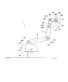
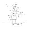
図1に示すロボット1は、その基台2が作業スペース下側の床面に設置される所謂床置き型の産業用ロボットである。基台2には基端アーム4、先端アーム5、第1ハンド6、第2ハンド7及びアタッチメント8がこの順で連設され、アタッチメント8の先端をなすフランジ面8aに各種作業用のツール9が取り付けられる。ツール9には、例えば搬送作業用の把持部材又は吸着部材、塗装作業用のガン、及び溶接作業用のトーチ等が含まれ、フランジ面8aには作業内容に応じて適宜選択されたツール9が着脱可能に取り付けられる。ここではツール9がフランジ面8aに取り付けられると、ツール9はアタッチメント8に対して相対変位しないものとする。
[First Embodiment]
A
基台2からアタッチメント8までの7つの部材2〜8は互いに相対回転可能に連結されている。つまり、基台2と旋回台3との連結部である第1ジョイントJT1において旋回台3の基台2に対する第1回転軸A1周りの回転が許容され、旋回台3の上端部と基端アーム4の一端部との連結部である第2ジョイントJT2において基端アーム4の旋回台3に対する第2回転軸A2周りの回転が許容され、基端アーム4の他端部と先端アーム5の一端部との連結部である第3ジョイントJT3において先端アーム5の基端アーム4に対する第3回転軸A3周りの回転が許容される。また、先端アーム5の他端部と第1ハンド6の一端部との連結部である第4ジョイントJT4において第1ハンド6の先端アーム5に対する第4回転軸A4周りの回転が許容され、第1ハンド6の他端部と第2ハンド7の一端部との連結部である第5ジョイントJT5において第2ハンド7の第1ハンド6に対する第5回転軸A5周りの回転が許容され、第2ハンド7の他端部とアタッチメント8の端部との連結部である第6ジョイントJT6においてアタッチメント8の第2ハンド7に対する第6回転軸A6周りの回転が許容される。
The seven
基台2が床面に適正に設置されると、第1回転軸A1は鉛直に指向し、第2及び第3回転軸A2,A3はそれぞれ水平に指向する。第4回転軸A4は第3回転軸A3と直交方向であって先端アーム5の延在方向に指向し、第5回転軸A5は第4回転軸A4と直交方向に指向し、第6回転軸A6は第5回転軸A5と直交方向に指向している。本実施形態では、後述するように第3回転軸A3が第4回転軸A4と交差し、第4回転軸A4が第5回転軸A5と交差し、第5回転軸A5が第6回転軸A6と交差している場合を例示する。また、第1回転軸A1が第2回転軸A2と捩れの関係にある場合を例示するが、これら両軸A1,A2は互いに交差していてもよい。
When the
第1ハンド6、第2ハンド7及びアタッチメント8はツール9に近い側に設けられる部材であり、これらはツール9の微細な動作を行わせるための構造体10(以下これを「手首装置」と呼ぶ)をなしている。第1乃至第3回転軸A1〜A3は、ツール9を手首装置10とともに水平旋回させたり揺動させたりする回転軸であり、ロボット1の所謂主軸をなしている。第4乃至第6回転軸A4〜A6は、手首装置10に設定される回転軸であり、所謂RBR型の手首軸をなしている。
The
第1乃至第6ジョイントJT1〜JT6にはそれぞれ第1乃至第6サーボモータM1〜M6が設けられており、各サーボモータM1〜M6が動作することによってこれに対応するジョイントJT1〜JT6において許容される各回転軸A1〜A6周りの回転が行われる。各サーボモータM1〜M6は互いに独立して動作可能であり、各回転軸A1〜A6周りの回転を互いに独立して行うことによりアタッチメント8に取り付けたツール9を任意の位置及び姿勢に任意の経路に沿って移動させることができる。
The first to sixth joints JT1 to JT6 are provided with first to sixth servomotors M1 to M6, respectively, which are permitted in the corresponding joints JT1 to JT6 when the servomotors M1 to M6 operate. The rotation about the rotation axes A1 to A6 is performed. The servo motors M1 to M6 can operate independently from each other, and the
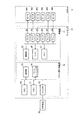
図2は図1に示すロボット1の制御系の構成を示すブロック図である。以降ではロボット1の構造的な構成要素には図1の参照符号を付して説明する。図2に示すコントローラ15は、所定の制御モードの中から現に設定されているモードに基づいて各サーボモータM1〜M6の駆動制御を行い、これによりツール9を適宜移動させる制御を実行する。この制御モードには、例えば、ロボット1の移動終了位置をコントローラ15に教示して記憶させるため、オペレータがロボット1をマニュアル操作で動作させるティーチモード、ティーチモードで教示された位置間での自動的な移動が適正に行われ得るか否かをチェックするため、動作計画に従ってロボット1を自動的に動作させるチェックモード、チェック終了後にロボット1を実用に供するため、ロボット1を自動的且つ継続的に動作させるリピートモード等が含まれる。
FIG. 2 is a block diagram showing the configuration of the control system of the
そして、コントローラ15は、サーボモータM1〜M6の駆動制御を行うための機能ブロックとして、ロボット動作演算部16及び制御部17を有している。また、コントローラ15はティーチペンダント等の外部装置30と接続可能となっており、オペレータは、外部装置30を利用することにより、例えばティーチモード及びチェックモードの実行開始指令の入力、ティーチモードの実行中におけるロボット1の動作のマニュアル操作、ティーチモードの実行中における移動開始位置及び移動終了位置の入力などを行うことができる。
And the
ロボット動作演算部16はCPU20、メモリ21、入出力部22、通信部23及びパワーシーケンス部24を有し、外部装置30は入出力部22に接続されることによってコントローラ15と通信可能となる。制御部17は通信部25、CPU26、メモリ27及びアンプ28を有しており、通信部25においてロボット動作演算部16と通信可能となっている。アンプ28は各サーボモータM1〜M6に個別に設けられ、各アンプ28は対応する1つのサーボモータと接続されている。
The robot
ティーチモードの実行中、オペレータは外部装置30において、各回転軸A1〜A6周りの回転を行うモードである「各軸モード」と、ツール9を所定の直交三次元座標系によって定義される軸方向に直進運動させたり各軸周りに回転運動させたりするモードである「直交座標系モード」とを切り替え可能となっている。
During execution of the teach mode, the operator uses the
「各軸モード」の設定時には、オペレータの操作に応じて、外部装置30から、ある回転軸周りに所定回転方向に回転させる指令が入出力部22に入力される。制御部17のCPU26は制御時間(例えば10msec)毎に入出力部22に入力される指令に基づいて、制御時間が経過する間における当該回転軸周りの目標回転変位量を算出する。この目標回転変位量は、制御時間と予め定められた制限移動速度(例えば250mm/s) 等から求まる。そして、この目標回転変位量に基づいて当該回転軸に対応するサーボモータの動作量の指令値を演算し、これをアンプ28に出力する。アンプ28は対応するサーボモータM1〜M6に指令値に応じた電流を供給し、これによりサーボモータが制御時間毎に指令値に準じた動作量だけ動作する。
When the “each axis mode” is set, a command to rotate in a predetermined rotation direction around a certain rotation axis is input from the
「直交座標系モード」の設定時には、ツール9の中心位置(所謂TCP,図3参照)を原点とした直交三次元座標系(例えば所謂ツール座標系)によって定義される3つの軸各々の向きにツール9を直進運動させることができるとともに、これら3つの軸各々を中心としてツール9を回転運動させることができ、オペレータの操作に応じて外部装置30から直進運動又は回転運動させる指令が入出力部22に入力される。ロボット動作部16のCPU20は制御時間毎に入出力部22に入力される指令に基づいて、ツール9がこの制御時間の経過後にツール9が位置すべき目標位置を算出する。この目標位置は、制御時間と予め定められたツール9の制限移動速度等から求まる移動距離に基づいて算出され、コントローラ15が演算可能なようにツール座標系において定義された座標データという形で算出される。通信部23は目標位置の座標データを制御部17に与える。制御部17のCPU26は目標位置の座標データの逆変換処理を行い、制御時間の経過後にツール9を目標位置まで移動させるために必要となる各回転軸A1〜A6の目標回転位置を算出する。そして、目標回転位置と現在の回転位置との偏差に基づき、各回転軸A1〜A6を制御時間の経過後に目標回転位置まで回転させるために必要となる各サーボモータM1〜M6の動作量の指令値を演算し、これを各アンプ28に出力する。アンプ28が対応するサーボモータM1〜M6に指令値に応じた電流を供給することにより、各サーボモータM1〜M6が制御時間毎に指令値に準じた動作量だけ動作し、ツール9が制御時間毎に目標位置まで直進する。
When the “orthogonal coordinate system mode” is set, the orientation of each of the three axes defined by the orthogonal three-dimensional coordinate system (for example, the so-called tool coordinate system) with the center position of the tool 9 (so-called TCP, see FIG. 3) as the origin is set. The
なお、各軸モードでは複数の回転軸周りの回転を同時に行わせることも可能であり、直進モードでは2以上の直進運動や回転運動を同時に行わせることも可能である。このような場合の各サーボモータM1〜M6の駆動制御も、前述したものに準じて実行される。 In each axis mode, it is possible to simultaneously rotate around a plurality of rotation axes, and in the straight-ahead mode, it is possible to simultaneously perform two or more straight-ahead movements and rotational movements. The drive control of each of the servo motors M1 to M6 in such a case is also executed according to the above-described one.
そして、オペレータは、ロボット1が所望する移動終了位置に達すると、外部装置30を利用してその位置を移動終了位置として設定することができる。この設定の指令に基づいてCPU20はメモリ21に移動終了位置を記憶させる。ティーチモードではこの一連の動作を繰り返し行うことが可能であり、メモリ21には1以上の移動終了位置が記憶されることとなる。
When the operator reaches the desired movement end position, the operator can set the position as the movement end position using the
ティーチモードが終了してチェックモードを開始するに際して、CPU20は移動終了位置同士の間の移動経路を示す情報と、その移動経路に沿った移動速度の情報とを含む動作計画を生成する。典型的にはこの移動速度の最大値が予め定めた制限移動速度(例えば250mm/s)に設定される。
When the teaching mode is ended and the check mode is started, the
チェックモードでロボット1を移動させる場合、ロボット動作部16のCPU20は移動経路の補間処理を行い、この移動経路上に制御時間毎の目標位置を設定する。制御部17のCPU26は、ロボット動作部16より制御時間毎に送られる目標位置の座標データに基づいて前述同様の処理を行い、各サーボモータM1〜M6の動作量の指令値を演算し、これを各アンプ28に出力する。アンプ28が対応するサーボモータM1〜M6に指令値に応じた電流を供給することにより、各サーボモータM1〜M6が制御時間毎に指令値に準じた動作量だけ動作し、ツール9が制御時間毎に目標位置まで移動する。
When the
なお、パワーシーケンス部24は、動作計画と無関係の動作(例えばサーボモータM1〜M6の電源投入直後の始動時の動作や、ロボット1の緊急停止時の動作など)を制御する機能ブロックであり、後述する速度規制の処理はティーチモードや通常のロボット1の動作時だけでなくパワーシーケンス部24により制御されるロボット1の動作時に実施されてもよい。
The
コントローラ15は、これら各モードでロボット1を移動させるに際し、ツール9を含めたロボット1のあらゆる表面部位の移動速度が所定の制限移動速度以下となるように各回転軸A1〜A6周りの角速度を規制する制御を実行する。本実施形態では、この速度規制の処理が煩雑になるのを避けるため、予め定められた複数の表面部位に着目し、これら表面部位の全ての移動速度が制限移動速度以下となるようにしている。その上で、ロボット1がどのような姿勢であっても予め定められた複数の表面部位の一つが制限移動速度で移動するようにし、複数の表面部位の最高移動速度を常に制限移動速度で維持するようにしてロボット1の動作性の向上を図っている。ここで制限移動速度とは、オペレータやコントローラ15の設計者が例えば安全規格等で定められた所定の上限値(例えば250mm/s 等)を超えない限りにおいて任意に設定可能な速度である。
When the
以下、各回転軸A1〜A6の角速度(すなわち制御時間毎の回転変位量)を規制するための処理について説明する。なお、コントローラ15の各機能ブロック16,17に個別対応してCPU20,26及びメモリ21,27が設けられる場合を例示したが、これらCPU20,26により実行される制御を統括して行う単一のCPUに替えたり、これらメモリ21,27内の各情報やCPUが実行する制御プログラムを一括して記憶する単一のメモリに替えてもよく、以降では便宜上これら複数のCPU及びメモリの区別が無いものとして説明する。つまり、この処理を行うために用いる情報や制御プログラムは何れのメモリ21,27に格納されてもよく、この処理は何れのCPU20,26によって実行されてもよい。また、以降ではコントローラ15の構成要素には図2の参照符号を付して説明する。
Hereinafter, a process for regulating the angular velocity (that is, the rotational displacement amount for each control time) of each of the rotation axes A1 to A6 will be described. In addition, although the case where the
まず、各軸モードにおける各回転軸A1〜A6の角速度の速度規制の処理について説明する。ここではツール9に近い側である第6回転軸A6から順に説明する。また、6軸ロボットの場合、基台2に設定された所定の位置を原点とする「ベース座標系」、各回転軸A1〜A6上の所定の位置を原点とする「ロボット座標系」、前述したTCPを原点とする「ツール座標系」など、様々な座標系の各々においてロボット1の位置を定義することが可能である。ここでTCPはツール9の所定の位置に設定されるものであり、後述するように本実施形態では先端面の中心位置に設定しているが、その他の任意の位置に設定可能である。なお、第1回転軸A1のロボット座標系を第1のロボット座標系と呼び、以下同様にして各回転軸に付与された序数とそれに対応するロボット座標系の序数とを対応させるものとしている。各座標系は設計データや各回転軸の回転位置に従って互いに変換可能である。そのため、以降の説明に挙げる各座標データを定義する座標系は実施形態の一つを例示したものに過ぎず、その他の座標系において各座標データが定義されていてもよい。
First, speed restriction processing for the angular speeds of the rotation axes A1 to A6 in each axis mode will be described. Here, the sixth rotation axis A6 that is closer to the
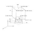
図3は第6回転軸A6の角速度を規制する処理の説明図である。図3ではツール9が仮想的に直方体状である場合を例示しており、このツール9の先端中心に前述したTCPを設定している旨を概念的に示している。
FIG. 3 is an explanatory diagram of processing for regulating the angular velocity of the sixth rotation axis A6. FIG. 3 exemplifies a case where the
オペレータは、外部装置30を利用してツール9の形状データを入力し、これをコントローラ15のメモリに記憶させることができる。この形状データは、例えば図3に示すように、オペレータが任意に設定したツール9の端点の位置を示す座標データによって実現される。この座標データは、ツール9をフランジ面8aに取り付けた状態としてフランジ面8aの中心O6を原点とした第6のロボット座標系で定義することも可能であるし、ツール座標系で定義することも可能である。図3では、直方体状であるとしたツール9の8個の頂点をそれぞれ上記端点t1〜t8として設定し、各端点t1〜t8の座標データを第6のロボット座標系で定義してメモリに記憶させた場合を概念的に例示している。ここでは便宜的に、ツール座標系及び第6のロボット座標系のX軸及びY軸がフランジ面8aの面方向を規定しており、ツール座標系のZ軸と第6のロボット座標系のZ軸とが一致しているものとする。つまり、第6回転軸A6はこのZ軸上にあり、ツール座標系と第6のロボット座標系とは、フランジ面8aの中心O6とTCPとの間のZ方向の距離のみに基づいて互いに変換可能であるとする。
The operator can input the shape data of the
ツール9の形状データを記憶させた場合、TCPと、8つの端点t1〜t8との合計9箇所の表面部位を考慮して第6回転軸A6の角速度(制御時間毎の回転変位量)が求められる。つまり、これら9箇所の表面部位を第6回転軸A6方向に見たときに第6回転軸A6から各表面部位までの軸直交方向の距離がそれぞれ求められる。言い換えると、9個の表面部位がフランジ面8aと平行な面であるXY平面上に投影され、このXY平面内において点となる第6回転軸A6から9個の表面部位の各々までのXY成分の距離が求められる。そして、求められた9個の距離が互いに比較されて最大値が抽出される。この最大値に対応する表面部位は第6回転軸A6周りの回転が生じたときに最大の移動速度で移動する部位となる。そこでコントローラ15のCPUは、この表面部位の移動速度が制限移動速度となる第6回転軸A6の制御時間当たりの回転変位量θ6(すなわち角速度)を算出する。そして、この回転変位量θ6に基づいて第6サーボモータM6の動作量の指令値を演算する。これにより、第6回転軸A6周りの回転を行わせるに際し、9個の表面部位の全ての移動速度が制限移動速度以下となってそのうちの1つの移動速度が制限移動速度となる。
When the shape data of the
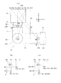
図4は第4及び第5回転軸A4,A5の角速度を規制する処理の説明図である。第5回転軸A5の制御時間当たりの回転変位量の算出には、TCPと、ツール9の各端点と、フランジ面8aの中心O6と、第2ハンド7に設定されている「許容最近部位」q5との合計11個の表面部位が考慮される。
FIG. 4 is an explanatory diagram of processing for regulating the angular velocities of the fourth and fifth rotation axes A4 and A5. For calculating the rotational displacement amount per control time of the fifth rotation axis A5, TCP, each end point of the
この「許容最近部位」とは、ある回転軸周りの回転が生じたときにその回転軸の回転を許容するジョイントに連結された部材の中から基台2に最も近い部材に着目し、その部材を当該回転軸方向に見たときに回転軸から軸直交方向に最も遠位にある表面部位をいう。ここで着目される部材の姿勢は、当該回転軸の回転位置のみに依存して変化し、それよりもツール9側に設定されている回転軸の回転に応じて変化するものではない。従って、当該部材を当該回転軸方向に見たときには、当該回転軸から軸直交方向に最も遠位にある表面部位は当該回転軸の回転位置に関わらず常に同じ部位であり、本書ではこの部位を許容最近部位として定義している。第5回転軸A5に関して言えば、第5ジョイントJT5によって回転が許容される部材7〜9のうち基台2に最も近い部材(すなわち第5ジョイントJT5に直接的に連結された部材6,7のうちツール9側に位置する部材)は第2ハンド7であるが、この第2ハンド7を第5回転軸A5方向に見たときに第5回転軸A5から軸直交方向に最も遠位にある表面部位q5が許容最近部位として設定される。この部位は、ロボット1の設計段階において各部材の寸法が定まることで予め決定しておくことが可能であり、コントローラ15のメモリには動作の事前に予めその位置を示す座標データが記憶される。このように許容最近部位を表面部位として考慮すると、ツール部材9が許容最近部位に対して回転軸寄りに位置する姿勢になっていたとしても、上記着目すべき部材の移動速度を制限移動速度以下に規制することが可能となる。なお、ある回転軸周りに回転する部材のうち最も基台側に位置する部材に、角速度の決定に考慮する表面部位を設定する場合を例示したが、その他の部材にこのような表面部位が設定されていてもよい。
This “allowable nearest part” refers to the member closest to the
この許容最近部位の概念は他の回転軸にも同様にして適用可能である。つまり、第4回転軸A4においては第1ハンド6を第4回転軸A4方向に見たときに第4回転軸A4から最も遠位にある表面部位q4、第3回転軸A3においては先端アーム5を第3回転軸A3方向に見たときに第3回転軸A3から最も遠位にある表面部位q3(図5参照)、第2回転軸A2においては基端アーム3を第2回転軸A2方向に見たときに第2回転軸A2から最も遠位にある表面部位q2(図5参照)、第1回転軸A1においては旋回台3を第1回転軸A1方向に見たときに第1回転軸A1から最も遠位にある表面部位q1(図5参照)がそれぞれ許容最近部位として扱われ得る。
The concept of the allowable nearest portion can be applied to other rotating shafts in the same manner. That is, on the fourth rotation axis A4, when the
なお、ここでは便宜的に第5及び第6回転軸A5,A6が互いに直交するように設定され、第5回転軸A5は第6のロボット座標系のX軸と平行に向くものと仮定する。つまり、第6のロボット座標系が規定するYZ平面は第5回転軸A5の直交平面となる。この場合において、第5及び第6回転軸A5,A6の交点O5を原点として第5のロボット座標系を定義すれば、第6のロボット座標系の原点O6の座標は、交点O5との間のZ方向の距離z5に基づいて、第5のロボット座標系では(0,0,z5)に変換される。 Here, for convenience, it is assumed that the fifth and sixth rotation axes A5 and A6 are set so as to be orthogonal to each other, and the fifth rotation axis A5 is parallel to the X axis of the sixth robot coordinate system. That is, the YZ plane defined by the sixth robot coordinate system is an orthogonal plane of the fifth rotation axis A5. In this case, if the fifth robot coordinate system is defined with the intersection O5 of the fifth and sixth rotation axes A5 and A6 as the origin, the coordinate of the origin O6 of the sixth robot coordinate system is between the intersection O5 and the intersection O5. Based on the distance z5 in the Z direction, the fifth robot coordinate system converts the distance to (0, 0, z5).
コントローラ15は、前述した第6回転軸A6と同様、11個の表面部位を第5回転軸A5方向に見たときにおける第5回転軸A5から各表面部位までの軸直交方向の距離をそれぞれ求める。つまり、11個の表面部位が第5回転軸A5の直交平面であるYZ平面上に投影され、このYZ平面内で点となる第5回転軸A5から11個の表面部位の各々までのYZ成分の距離が求められ、求めた11個の距離が互いに比較されて最大値が抽出され、この最大値に対応する表面部位の移動速度が制限移動速度となる第5回転軸A5の制御時間当たりの回転変位量θ5(すなわち角速度)が算出される。そして、この回転変位量θ5に基づいて第5サーボモータM5の動作量の指令値が演算される。これにより、第5回転軸A5周りの回転を行わせるに際し、11個の表面部位の全ての移動速度が制限移動速度以下となってそのうちの1つの移動速度が制限移動速度となる。
Similarly to the above-described sixth rotation axis A6, the
なお、第5回転軸A5から許容最近部位q5までのYZ成分の距離は、第5のロボット座標系で定義される許容最近部位q5の座標データを用いて容易に求めることができる。他方、その他の10個の表面部位については、第6のロボット座標系又はツール座標系で定義された座標を第5のロボット座標系に変換する必要がある。これら10個の表面部位のYZ成分の距離の導出に関し、ここではツールの端点の1つtnに着目して説明する。図4(a)に示す端点tnの座標(Xn,Yn,Zn)は第6のロボット座標系で定義されたものとする。図4(b)に示すように、ツール9は第6回転軸A6周り(すなわちZ軸周り)に回転するため、前述した第6回転軸A6周りの回転変位量θ6に基づいてXY平面内を移動する。コントローラ15は、第6のロボット座標系において定義された座標(Xn,Yn,Zn)とこの回転変位量θ6とに基づいて、この回転後の端点tn′の座標(Xn′,Yn′,Zn)を算出する。図4(a)に戻り、次いで、第6のロボット座標系と第5のロボット座標系の各原点O5,O6間のZ方向の距離z5を用い、回転後の端点tn′の座標(Xn′,Yn′,Zn)を、第5のロボット座標系において定義される座標(Xn′,Yn′,Zn+z5)へと変換する。この座標(Xn′,Yn′,Zn+z5)に基づいて、端点tn′の原点O5からのYZ成分の距離dtnが次式より求められる。
The distance of the YZ component from the fifth rotation axis A5 to the allowable nearest part q5 can be easily obtained using the coordinate data of the allowable nearest part q5 defined in the fifth robot coordinate system. On the other hand, for the other 10 surface parts, it is necessary to convert the coordinates defined in the sixth robot coordinate system or the tool coordinate system to the fifth robot coordinate system. The derivation of the YZ component distances of these ten surface parts will be described here focusing on one of the tool endpoints tn. Assume that the coordinates (Xn, Yn, Zn) of the end point tn shown in FIG. 4A are defined in the sixth robot coordinate system. As shown in FIG. 4B, since the

この要領で、第5回転軸A5とは独立して第6回転軸A6周りに回転し得るTCP、8つの端点t1〜t8、及びフランジ面8aの中心O6の10個の表面部位について、第5回転軸A5上の原点O5からのYZ成分の距離が求められる。
In this manner, for the ten surface portions of the TCP that can rotate around the sixth rotation axis A6 independently of the fifth rotation axis A5, the eight end points t1 to t8, and the center O6 of the
第4回転軸A4の制御時間当たりの回転変位量の算出においても、TCP、ツール9の各端点、フランジ面8aの中心O6、及び第1ハンド6に設定されている許容最近部位q4との合計11個の表面部位が考慮される。
Also in the calculation of the rotational displacement amount per control time of the fourth rotation axis A4, the total of the TCP, each end point of the
なお、ここでは、第4及び第5回転軸A4,A5は互いに交差するよう設定され、第4回転軸A4と第4ジョイントJT4の先端面との交点O4を原点とする直交三次元座標系が第4のロボット座標系として定義されるものとしている。また、この第4のロボット座標系では、図4(a)の記載を基準にして、Y軸上に第4回転軸A4が位置し、ZX平面が第4回転軸A4の直交平面となるものと仮定する。 Here, the fourth and fifth rotation axes A4 and A5 are set so as to intersect with each other, and an orthogonal three-dimensional coordinate system having an origin at an intersection O4 between the fourth rotation axis A4 and the tip surface of the fourth joint JT4 is provided. It is assumed that the fourth robot coordinate system is defined. In the fourth robot coordinate system, the fourth rotation axis A4 is located on the Y axis and the ZX plane is an orthogonal plane of the fourth rotation axis A4 with reference to the description of FIG. Assume that
コントローラ15は、前述した第5回転軸A5と同様、11個の表面部位を第4回転軸A4方向に見たときにおける第4回転軸A4から各表面部位までの軸直交方向の距離をそれぞれ求める。つまり、11個の表面部位が第4回転軸A4の直交平面であるZX平面上に投影され、このZX平面内で点となる第4回転軸A4から11個の表面部位の各々までのZX成分の距離が求められ、求めた11個の距離が互いに比較されて最大値が抽出され、この最大値に対応する表面部位の移動速度が制限移動速度となる第4回転軸A4の制御時間当たりの回転変位量(すなわち角速度)が算出される。そして、この回転変位量に基づいて第4サーボモータM4の動作量の指令値が演算される。これにより、第4回転軸A4周りの回転を行わせるに際し、11個の表面部位の全ての移動速度が制限移動速度以下となってそのうちの1つの移動速度が制限移動速度となる。
Similarly to the above-described fifth rotation axis A5, the
なお、第4回転軸A4から許容最近部位q4までのZX成分の距離は、第4のロボット座標系で定義される許容最近部位q4の座標データを用いて容易に求めることができる。他方、その他の10個の表面部位については、第6のロボット座標系又はツール座標系で定義された座標を第4のロボット座標系に変換する必要がある。これら10個の表面部位のZX成分の距離の導出に関し、ここではツールの端点の1つtmに着目して説明する。図4(a)に示す端点tmの座標(Xm,Ym,Zm)も第6のロボット座標系に設定されたものとする。この端点tmについても、まず、第5回転軸A5の回転変位量θ5を算出したときと同様、第6回転軸A6の回転変位量θ6と距離z5を考慮して第5のロボット座標系に定義される座標(Xm′,Ym′,Zm+z5)へと変換する。次いで、図4(c)に示すように、ツール9は第5回転軸A5周り(すなわちX軸周り)に回転するため、前述した第5回転軸A5周りの回転変位量θ5に基づいてYZ平面内を移動する。コントローラ15は、第5のロボット座標系に定義された座標(Xm′,Ym′,Zm+z5)とこの回転変位量θ5とに基づき、この回転後の端点tm″の座標(Xm′,Ym″,(Zm+z5)′)を算出する。図4(a)に戻り、次いで、この座標(Xm′,Ym″,(Zm+z5)′)に基づいて、端点tm″の原点O4からのZX成分の距離dtmが次式より求められる。
Note that the distance of the ZX component from the fourth rotation axis A4 to the allowable closest part q4 can be easily obtained using the coordinate data of the allowable closest part q4 defined in the fourth robot coordinate system. On the other hand, for the other 10 surface parts, it is necessary to convert the coordinates defined in the sixth robot coordinate system or the tool coordinate system to the fourth robot coordinate system. The derivation of the ZX component distances of these ten surface parts will be described here by focusing on one of the tool end points tm. Assume that the coordinates (Xm, Ym, Zm) of the end point tm shown in FIG. 4A are also set in the sixth robot coordinate system. The end point tm is also defined in the fifth robot coordinate system in consideration of the rotational displacement amount θ6 of the sixth rotational axis A6 and the distance z5 as in the case of calculating the rotational displacement amount θ5 of the fifth rotational axis A5. To the coordinates (Xm ′, Ym ′, Zm + z5). Next, as shown in FIG. 4C, since the
この要領で、第4回転軸A4とは独立して第5及び第6回転軸A5,A6周りに回転し得るTCP、8つの端点t1〜t8及びフランジ面8aの中心O6の10個の表面部位について、第4回転軸A4上の原点O4からのZX成分の距離が求められる。
In this manner, 10 surface portions of TCP, eight end points t1 to t8 and the center O6 of the
このように手首装置10に設定された第4乃至第6回転軸A4〜A6の各角速度は、TCPと、ツール9の端点t1〜t8の位置と、当該回転軸に対応する許容最近部位及びフランジ面8aの中心O6(第6回転軸A6を除く)とを用いて求められる。他方、所謂ロボット1の主軸をなす第1乃至第3回転軸A1〜A3については、座標変換処理を行う回数や考慮しなければならない他の回転軸の回転変位量が多いため、原則的にTCPと許容最近部位とフランジ面8aの中心O6の3個の表面部位を考慮してその角速度を求めるようにしており、これにより処理が煩雑になるのを避けることができる。なお、これら主軸A1〜A3からツール9の端点t1〜t8までの距離は、手首装置10がどのような姿勢になっていたとしても、TCP又はフランジ面8aの中心O6までの距離と大して変わらない。このためTCP及びフランジ面8aの中心O6を表面部位として考慮してさえいれば、ツール9の端点t1〜t8を考慮しなくとも、主軸A1〜A3の各々を中心とした回転が行われたときにツール9が制限移動速度を超えて移動するような状況は起こりにくいと考えられ、このように処理を簡略化しても問題となりにくい。なお、第1乃至第3回転軸A1〜A3の角速度を求めるための処理を簡略化するためにツール9の端点t1〜t8を表面部位として考慮しない場合には、各回転軸A1〜A3の回転変位量を求めるために用いる制限移動速度を第4乃至第6回転軸A4〜A6の回転変位量を求めるために用いた制限移動速度よりも小さくなるように設定してもよい。勿論、第1乃至第3回転軸A1〜A3の角速度を求めるためにツール9の端点t1〜t8を表面部位として考慮してもよい。
As described above, the angular velocities of the fourth to sixth rotation axes A4 to A6 set in the
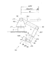
図5は第1乃至第3回転軸A1〜A3の角速度を規制する処理の説明図である。第3回転軸A3の角速度の算出においては、TCP、フランジ面8aの中心O6、及び先端アーム5に設定された許容最近部位q3との3個の表面部位が考慮される。そして、前述した第4乃至第6回転軸A4〜A6と同様、3個の表面部位を第3回転軸A3方向に見たときにおける第3回転軸A3から各表面部位までの軸直交方向の距離をそれぞれ求める。つまり、3個の表面部位が第3回転軸A3の直交平面に投影され、この平面内で点となる第3回転軸A3から3個の表面部位の各々までの距離が求められ、求めた3個の距離が互いに比較されて最大値が抽出され、この最大値に対応する表面部位の移動速度が制限移動速度となる第3回転軸A3の制御時間当たりの回転変位量(すなわち角速度)が算出される。そして、この回転変位量に基づいて第3サーボモータM3の動作量の指令値が演算される。これにより、第3回転軸A3周りの回転を行わせるに際し、3個の表面部位の全ての移動速度が制限移動速度以下となってそのうちの1つの移動速度が制限移動速度となる。なお、図5は第3回転軸A3方向に見たロボット1の模式図となっており、TCPの移動速度が制限移動速度となる場合を例示している。前述したように3個の表面部位は互いに異なる座標系において定義されていたとしても、第3回転軸A3の位置を基準にして互いに関連付け可能となっている。
FIG. 5 is an explanatory diagram of processing for regulating the angular velocities of the first to third rotation axes A1 to A3. In the calculation of the angular velocity of the third rotation axis A3, three surface portions including the TCP, the center O6 of the
第2回転軸A2の角速度の算出においては、TCP、フランジ面8aの中心O6、及び基端アーム4に設定された許容最近部位q2との3個の表面部位が考慮され、第3回転軸A3と同じ要領で第2回転軸A2の制御時間当たりの回転変位量(すなわち角速度)が算出され、この回転変位量に基づいて第2サーボモータM2の動作量の指令値が算出される。これにより、第2回転軸A2周りの回転を行わせるに際し、3個の表面部位の全てが制限移動速度以下となってそのうちの1つの移動速度が制限移動速度となる。なお、図5は第2回転軸A2方向に見たロボット1の模式図となっており、TCPの移動速度が制限移動速度となる場合を例示している。
In the calculation of the angular velocity of the second rotation axis A2, three surface parts including the TCP, the center O6 of the
第1回転軸A1の角速度の算出においては、TCP、フランジ面8aの中心O6、及び基端アーム4に設定された許容最近部位q2との3個の表面部位に、更に基端アーム4の他端部(第3ジョイントJT3)の表面部位を加えた合計4個の表面部位が考慮される。第1回転軸A1の制御時間当たりの回転変位量(すなわち)角速度を算出する手順は、考慮する表面部位の個数が1個増えることのみを除き、第2及び第3回転軸A2,A3に関する回転変位量を算出する手順と同じである。このようにして求めた回転変位量に基づいて第1サーボモータM1の動作量の指令値を算出することにより、第1回転軸A1周りの回転を行わせるに際して、4個の表面部位の全てが制限移動速度以下となってそのうちの1つの移動速度が制限移動速度となる。
In the calculation of the angular velocity of the first rotation axis A1, in addition to the three surface portions of the TCP, the center O6 of the
このように第1回転軸A1に限り、角速度の算出のために考慮する表面部位の中に、第1ジョイントJT1により回転が許容される部材3〜9のうち基台3に最も近い旋回台2だけでなく、その先に連結されている基端アーム4の表面部位が含まれている。これは、基端アーム4が基台2からツール9までの部材の中でも特に長尺のものであって、第1回転軸A1方向に見て旋回台3よりも外側に位置し易く、先端アーム5の他端部(第4ジョイントJT4)が基端アーム4の他端部(第3ジョイントJT3)に対して第1回転軸A1寄りに位置しがちであってTCP及びフランジ面8aの中心O6が基端アーム4の他端部よりも第1回転軸A1寄りに位置しがちであるためである。図5では、ロボット1の動作時において一般に見られる基端アーム4と先端アーム5とが折り畳まれている場合を例示しており、TCPよりも基端アーム4の他端部(第3ジョイントJT3)の表面部位が第1回転軸A1から遠位にある場合を例示している。
As described above, the
基端アーム4の他端部を第1回転軸A1方向に見たときにおける第1回転軸O1から該他端部までの距離dJT3は、第1回転軸A1から第2回転軸A2までの第1回転軸A1の直交平面内での距離をd1、第2回転軸A2の回転位置をθ2,第2回転軸A2と第3回転軸A3(すなわち基端アーム4の各揺動支軸)との間の直線距離をd2、第3回転軸A3から基端アーム4の他端部の表面部位までの距離をd3とすると、式:dJT3=|d1+d2sinθ2|+d3 で表される。
The distance dJT3 from the first rotation axis O1 to the other end when the other end portion of the
ここで、回転位置θ2は基端アーム4が鉛直に延びる状態を0とし、第1回転軸A1に対して遠ざかる方向に基端アーム4が揺動すると正側に増加し、第1回転軸A1に対して近づく方向に基端アーム4が揺動すると負側に増加するものとしている。図5は回転位置θ2が負の値をとる場合を例示しており、このように回転位置θ2が負であっても距離dJT3を算出できるように上記式では(d1+d2sinθ2)の絶対値をとるようにしている。第1回転軸A1の角速度の算出には、このようにして算出された距離dJT3が、第1回転軸A1から他の3個の表面部位の各々までの距離と比較されることとなる。
Here, the rotational position θ2 is set to 0 when the
このように、各回転軸A1〜A6における制御時間当たりの回転変位量が、当該回転軸方向に見て当該回転軸からの距離が最大となる表面部位の移動速度が制限移動速度となるようにして決定されている。そのため、ロボット1の表面部位の全てを制限移動速度以下で移動させることができる。しかも、ロボット1の姿勢がどのようなものであっても表面部位の最高速度が制限移動速度となるため、無用にロボット1の動作速度が遅くなることもなく、ロボット1の動作性が向上する。より具体的にいえば、ティーチモードを実行してロボット1の移動停止位置を教示するための作業に要する時間や、チェックモードでのロボット1の動作に要する時間を短縮することができ、ロボット1がリピートモードで動作して実用に供されるまでに要する時間を短縮できる。
As described above, the rotational displacement amount per control time in each of the rotation axes A1 to A6 is set such that the movement speed of the surface portion where the distance from the rotation axis is maximum when viewed in the rotation axis direction becomes the limit movement speed. Has been determined. Therefore, all the surface parts of the
また、本実施形態においてはツール9の形状データを考慮して回転軸の角速度を求めている。このため、ガンやトーチのように長尺のツールを取り付けた場合であっても、ガンやトーチの先端を制限移動速度以下で移動させることができる。なお、本実施形態ではツール9の形状データのみをメモリに記憶させることができ、これを考慮して回転軸の角速度を求めるとしたが、ツール9として搬送作業用の把持部材や吸着部材を取り付ける場合、これら部材の端点のみならずこれら部材により搬送されるワークの形状データを入力してもよい。これによりワークの端点を制限移動速度以下で移動させることができるようになる。
In the present embodiment, the angular velocity of the rotation axis is obtained in consideration of the shape data of the
次に、直交座標系モードにおける各回転軸A1〜A6の角速度の速度規制の処理について説明する。直交座標系モードにおいては、前述したように、まず、制御時間の経過後にツール9が位置すべき目標位置が算出される。この目標位置は、TCP及び/又はフランジ面8aの中心O6の目標位置としている。そのため、目標位置は、TCP及び/又はフランジ面8aの中心O6の現在(すなわち制御時間の計時前)の座標と、制限移動速度とを用いた演算により、TCP及び/又はフランジ面8aの中心O6の制御時間経過後の目標座標という形で算出される。すなわち、TCP及び/又はフランジ面8aの中心O6が、制御時間が経過する間にここで算出された目標位置まで移動したとすれば、これら表面部位の移動速度が制限移動速度となる。そして、この目標位置を示す目標座標の逆変換処理を行うことにより、TCP及び/又はフランジ面8aの中心O6が制限移動速度で目標座標まで移動するために必要となる各回転軸A1〜A6周りの回転変位量が算出される。
Next, the speed restriction processing for the angular velocities of the rotation axes A1 to A6 in the orthogonal coordinate system mode will be described. In the orthogonal coordinate system mode, as described above, first, the target position where the
次いで、コントローラ15のCPUは、各回転軸A1〜A6に関し、求められた回転変位量で回転した場合に、TCP及びフランジ面8aの中心O6以外に予め設定されている表面部位の制御時間当たりの移動量(すなわち移動速度)を算出する。各回転軸の移動量の算出に考慮する表面部位は、上記の各軸モードにおいて各回転軸の角速度の算出に考慮した表面部位と同じである。つまり、例えば第1回転軸A1においては旋回台3に設定された許容最近部位q1、及び第3ジョイントJT3の2個の表面部位の移動量が求められ、例えば第4回転軸A4においては第1ハンド6に設定された許容最近部位q4、及びツール9の8つの端点t1〜t8の9個の表面部位の移動量が求められ、全て合わせると30個の移動量が求められることとなる。
Next, when the CPU of the
そして、これら移動量のうち最大となるものを抽出する。抽出された移動量がTCP及び/又はフランジ面8aの中心O6の移動量であった場合には、当初算出された回転変位量に基づいて各サーボモータM1〜M6の動作量の指令値を算出し、指令値に基づいて各サーボモータM1〜M6を駆動する。これによりTCP及び/又はフランジ面8aの中心O6の移動速度が制限移動速度であって、それ以外の表面部位の移動速度は制限移動速度となる。他方、抽出された移動量がTCP及び/又はフランジ面8aの中心O6以外の表面部位のものであった場合には、その表面部位の制御時間当たりの移動量が制限移動速度と等しくなるような、TCP及び/又はフランジ面8aの中心O6の目標位置を改めて算出する。ここで算出される目標位置は当初算出された目標位置よりも手前側に設定されることとなる。コントローラ15のCPUは、再算出された目標位置を示す目標座標の逆変換処理を行い、TCP及び/又はフランジ面8aの中心O6がこの目標座標まで移動するために必要となる各回転軸A1〜A6周りの回転変位量を改めて算出する。そして、再算出された回転変位量に基づいて各サーボモータM1〜M6の動作量の指令値を算出し、指令値に基づいて各サーボモータM1〜M6を駆動する。これにより、最大の移動量になるとして抽出された表面部位の移動速度が制限移動速度であって、TCP及びフランジ面8aの中心O6を含むその他の表面部位の移動速度が制限移動速度以下となる。
Then, a maximum one of these movement amounts is extracted. When the extracted movement amount is the movement amount of the center O6 of the TCP and / or the
このように、本実施形態によれば、直交座標系モードの設定時においても、ロボット1の表面部位の全てを制限移動速度以下で移動させることができ、ロボット1の姿勢がどのようなものであっても表面部位の最高速度が制限移動速度となる。
As described above, according to the present embodiment, even when the orthogonal coordinate system mode is set, all of the surface portions of the
[第2実施形態]
図6は本発明の第2実施形態に係る多軸ロボットの一例として示す6軸垂直型のロボット51の模式図である。本実施形態のロボット51は第1実施形態に対して構造が相違しており、これに伴い第1及び第2回転軸A1,A2の角速度を求める処理が相違している。その他の点では第1実施形態と共通しており、この共通点については第1実施形態と同じ参照符号を付して重複する詳細説明を省略する。また、ここでは各軸モードにおいて角速度を規制する処理についてのみ説明するが、直進モードにおいても第1実施形態で説明した各軸モードとの関連性に基づき、本実施形態を同様にして適用することができる。
[Second Embodiment]
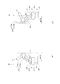
FIG. 6 is a schematic diagram of a 6-axis
図6に示すロボット51の旋回台2と第3ジョイントJT3′との間には、基端アーム4と平行に並ぶようにして平行リンク52が跨って設けられており、平行リンク52の一端部が旋回台2に対して揺動可能に連結され、平行リンク52の他端部が第3ジョイントJT3′に揺動可能に連結されている。このため、この第3ジョイントJT3′は、第1実施形態と同様にして基端アーム4と先端アーム5とを相対回転可能に連結して第3回転軸A3が設定されている主部JT3aと、主部JT3aから第3回転軸A3の軸直交方向に突出して設けられて平行リンク52の他端部が連結される突部JT3bとを有している。ここでいう「平行」とは、平行リンク52の2つの揺動支軸A2′,A3′を結ぶ直線と、基端アーム4の2つの揺動支軸A2,A3とを結ぶ直線とが互いに平行であることを意味し、平行リンク52及び基端アーム4の各々の揺動支軸間での形状は任意のものにすることができる。第2ジョイントJT2において許容される第2回転軸A2周りの回転が行われると、平行リンク52は揺動支軸A2′を中心にして基端アーム4とともに揺動し、基端アーム4と「平行」に並ぶ状態が維持される。
A
第2回転軸A2の角速度の算出には、第2回転軸A2方向に見たときにTCP、フランジ面8aの中心O6、基端アーム5及び平行リンク52に含まれている許容最近部位q2′の3個の表面部位が考慮される。
In calculating the angular velocity of the second rotation axis A2, the allowable nearest part q2 ′ included in the TCP, the center O6 of the
図7は図6に示すロボット51において第1回転軸A1の角速度を規制するための処理の説明図である。本実施形態においても、第1回転軸A1の角速度の算出に際し、TCP、フランジ面8aの中心O6、旋回台2に含まれる許容最近部位q1のみならず、第3ジョイントJT3′の表面部位が考慮される。ここで、平行リンク52の揺動支軸A2′は第1回転軸A1方向に見て第1回転軸A1と第2回転軸A2との間に位置している。このため、図7(a)に示すように、基端アーム4の回転角度が正側であって基端アーム4が延長に延びる状態から第1回転軸A1に対して遠ざかる方向に揺動しているときには、突部JT3bは第3回転軸A3よりも第1回転軸A1寄りに位置するようになり、第3ジョイントJT3′を第1回転軸方向A1に見て第1回転軸A1からの距離が最大となる表面部位は、第1実施形態と同様にして基端アーム4と先端アーム5とが連結されて第3回転軸A3が設定された主部JT3aの表面部位となる。
FIG. 7 is an explanatory diagram of processing for regulating the angular velocity of the first rotation axis A1 in the
他方、図7(b)に示すように基端アーム4の回転角度θ2′が負側であって基端アーム4が鉛直に延びる状態から第1回転軸A1へと近づく方向に揺動しているときには、突部JT3bは第3回転軸A3よりも第1回転軸A1から離れて位置するようになり、第3ジョイントJT3′を第1回転軸方向A1に見て第1回転軸A1からの距離が最大となる表面部位は、突部JT3bの表面部位となる。
On the other hand, as shown in FIG. 7B, the rotation angle θ2 ′ of the
そして、第2回転軸A2が0に近い所定の「臨界回転角度」に位置すると、第1回転軸A1から主部JT3aまでの距離と突部JT3bまでの距離とが等しくなる。なお、この臨界回転角度は、平行リンク52及び基端アームの寸法や、第1乃至第3回転軸A1〜A3及び平行リンク52の揺動支軸A1′,A2′の間の位置関係に応じて変更される。
When the second rotation axis A2 is positioned at a predetermined “critical rotation angle” close to 0, the distance from the first rotation axis A1 to the main portion JT3a is equal to the distance to the protrusion JT3b. The critical rotation angle depends on the dimensions of the
コントローラ15は、第1回転軸A1の角速度を算出するに際し、まず第2回転軸A2の回転角度がこの臨界回転角度に対して正側にあるか負側にあるのかを検知する。検知した回転角度が臨界回転角度に対して正側であったときには、第1回転軸方向A1に見たときの第1回転軸A1からTCPまでの距離、第1回転軸A1からフランジ面8aの中心O6までの距離、第1回転軸A1から旋回台3に設定された許容最遠部位q1までの距離、及び第1回転軸A1から第3ジョイントJT3′の主部JT3aの表面部位までの距離が求められ、求めた4個の距離が互いに比較されて最大値が抽出され、この最大値に対応する表面部位の移動速度が制限移動速度となる第1回転軸A1の制御時間当たりの回転変位量(すなわち角速度)が算出される。そして、この回転変位量に基づいて第1サーボモータM1の動作量の指令値が演算される。これにより、第1回転軸A1周りの回転を行わせるに際し、4個の表面部位の全ての移動速度が制限移動速度以下となってそのうちの1つの移動速度が制限移動速度となる。他方、検知した回転角度が臨界回転角度に対して負側であったときには、第1回転軸A1から第3ジョイントJT3′の主部JT3aの表面部位までの距離に替えて第1回転軸A1から第3ジョイントJT3′の突部JT3bまでの距離が求められ、以下同様にして第1回転軸A1の制御時間当たりの回転変位量が算出される。
When calculating the angular velocity of the first rotation axis A1, the
このように平行リンクを備えた場合には、第2回転軸A2の回転角度に応じて第3ジョイントJT3′の表面部位の中で第1回転軸A1から最も離れた部位が、主部JT3aであるのか突部JT3bであるのかを判断し、その判断結果に基づいて第1回転軸A1の角速度を求めるようにしているため、第2回転軸A2の回転角度が負であっても突部JT3bの移動速度を制限移動速度以下に規制することができる。 When the parallel link is provided in this way, the portion of the surface portion of the third joint JT3 ′ that is farthest from the first rotation axis A1 according to the rotation angle of the second rotation axis A2 is the main portion JT3a. Since it is determined whether there is a protrusion JT3b and the angular velocity of the first rotation axis A1 is obtained based on the determination result, even if the rotation angle of the second rotation axis A2 is negative, the protrusion JT3b The moving speed can be restricted to a speed lower than the limit moving speed.
なお、ここでは平行リンク52の一端部の揺動支点A2′を第1回転軸A1と第2回転軸A2との間に配置したため、第2回転軸A2の回転角度が負であるときに突部JT3bの表面部位を考慮する必要があったが、第1回転軸A1から揺動支点A2′までの距離が第2回転軸A2までの距離よりも大きくなるときには、第2回転軸A2の回転角度が正となったときに突部JT3bの表面部位を考慮して第1回転軸A1の角速度を求めるように適宜処理内容が変更される。但し、平行リンク52の一端部の揺動支点A2を本実施形態のように配置することにより、基台2に対して平行リンク52をコンパクトに配置することができる点で有利である。
Here, since the swing fulcrum A2 ′ at one end of the
[第3実施形態]
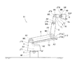
図8は本発明の第3実施形態に係る多軸ロボットの一例として示す6軸垂直型のロボット101の模式図である。本実施形態は第1及び第2実施形態に対してロボットの据付箇所が相違している。その他の点では上記実施形態とほぼ同一であり、上記各実施形態と同一の構成については同一の符号を付して重複する詳細説明を省略している。また、ここでも各軸モードにおいて角速度を規制する処理についてのみ説明するが、直進モードにおいても第1実施形態で説明した各軸モードとの関連性に基づき、本実施形態を同様にして適用することができる。
[Third Embodiment]
FIG. 8 is a schematic diagram of a 6-axis
図8に示すロボット101は、基台2が作業スペース上側の棚面に設置される所謂棚置き型の産業用ロボットである。このため、作業を行うときなどには、旋回台103に対して基端アーム4が水平に張り出し、基端アーム4の他端部に対して先端アーム5が下側に延びるような姿勢となる傾向にある。
A
本実施形態においても、第1回転軸A1の角速度の算出に際しては、TCP、フランジ面8aの中心O6、及び旋回台3に設定される許容最近部位q1に、第3ジョイントJT3″の表面部位を加えた合計4個の表面部位が用いられる。
Also in the present embodiment, when calculating the angular velocity of the first rotation axis A1, the surface portion of the third joint JT3 ″ is placed on the TCP, the center O6 of the
第1回転軸A1方向に見たときの第1回転軸A1から第3ジョイントJT3″の表面部位までの距離dJT3″は、第2回転軸A2と第3回転軸A3との間の直線距離をd2、第2回転軸A2の回転角度をθ2″、第3回転軸A3から第3ジョイントJT3″の表面部位までの距離をd3とすると、式:dJT3″=d2cosθ2″+d3 で表される。 The distance dJT3 ″ from the first rotation axis A1 to the surface portion of the third joint JT3 ″ when viewed in the direction of the first rotation axis A1 is a linear distance between the second rotation axis A2 and the third rotation axis A3. When d2, the rotation angle of the second rotation axis A2 is θ2 ″, and the distance from the third rotation axis A3 to the surface portion of the third joint JT3 ″ is d3, the expression is expressed by the following formula: dJT3 ″ = d2cos θ2 ″ + d3.
ここで、回転角度θ2″は基端アーム4が水平に延びる状態を0としている。ここでは第2実施形態のように絶対値をとる項を設定していないが、基端アーム4が鉛直に延びる状態を超えて図示する状態と反対側まで揺動するようなことがないため、実用上は絶対値をとる項を設定しなくても問題とならない。また、上記式は、第1回転軸A1方向に見て第2回転軸A2が第1回転軸A1上を通過するよう旋回台103を構成した場合を想定しているが、第2回転軸A2と第1回転軸A1とがこのような位置関係にない場合には、適宜第1回転軸A1と第2回転軸A2との位置関係(すなわち距離)をパラメータとする項が上記式に加えられる。
Here, the rotation angle θ2 ″ is set to 0 when the
本実施形態のように第1回転軸A1方向に見て第3ジョイントJT3″の表面部位が最遠部位となる傾向にある棚置き型のロボット101においては、第1回転軸A1の角速度を求めるために第3ジョイントJT3″の表面部位を考慮するのは特に有効となる。なお、本実施形態においても基端アーム4と平行に並ぶ平行リンクを第2実施形態と同様にして設けてもよい。
In the shelf-
これまで本発明の実施形態について説明したが、上記構成は本発明の範囲内で適宜変更可能である。例えば手首装置10に設定される回転軸として所謂RBR型の手首軸を例示したが、所謂BBR型の手首軸や3R型の手首軸であってもよい。また、多軸ロボットとして6軸垂直型の産業用ロボットを例示したが、ロボットの軸数は6つに限られないし、水平型や直角座標型のロボットにも好適に適用することができる。また産業用途に限らず、他の用途で利用されるロボットにも好適に適用することができる。また、本発明に係る速度制御装置として例示したコントローラ15はロボット1の例えば基台2に取り付けられていてもよいし、ロボット1と遠隔に配置されていて物理的に着脱可能な形態で接続されていてもよい。
Although the embodiments of the present invention have been described so far, the above configuration can be appropriately changed within the scope of the present invention. For example, the so-called RBR type wrist shaft is exemplified as the rotation axis set in the
本発明はロボットの動作速度を適正に制限しつつもその動作速度をなるべく高くすることができるという優れた作用効果を奏し、表面部位に速度制限をかける必要がある多軸ロボットに利用すると有益である。 INDUSTRIAL APPLICABILITY The present invention has an excellent effect that the operation speed can be increased as much as possible while appropriately limiting the operation speed of the robot, and is useful when used for a multi-axis robot that needs to limit the speed of the surface portion. is there.
A1〜A6 第1〜第6回転軸
JT1〜JT6 第1〜第6ジョイント
JT3′,JT3″ 第3ジョイント
JT3a 主部
JT3b 突部(連結部分)
M1〜M6 第1〜第6サーボモータ
1,51,101 ロボット
2 基台
3,103 旋回台(第1の連結部材)
4 基端アーム(第2の連結部材)
5 先端アーム(第3の連結部材)
6 第1ハンド(連結部材)
7 第2ハンド(連結部材)
8 アタッチメント(連結部材)
9 ツール
10 手首装置
15 コントローラ(速度制御装置)
21,25,28 CPU
22,26,28 メモリ
52 平行リンク(平行部材)
A1 to A6 First to sixth rotating shafts JT1 to JT6 First to sixth joints JT3 ′, JT3 ″ Third joint JT3a Main portion JT3b Protruding portion (connection portion)
M1 to M6 1st to
4 Proximal arm (second connecting member)
5 Tip arm (third connecting member)
6 First hand (connection member)
7 Second hand (connecting member)
8 Attachment (connection member)
9
21, 25, 28 CPU
22, 26, 28
Claims (4)
前記ツール部材の移動時に各回転軸の角速度を制御する速度制御装置を備え、
前記速度制御装置が、前記複数の連結部材及び前記ツール部材において予め設定された複数の表面部位の移動速度のうち最高移動速度が所定の制限移動速度となるように当該回転軸の角速度を求め、
前記複数の連結部材は、前記ツール部材が取り付けられる連結部材を含む手首装置を構成すると共にその回転軸が手首軸をなす第1部材群と、前記基台を前記手首装置に接続すると共にその回転軸が主軸をなす第2部材群とを含み、
各手首軸の角速度を求めるに際して前記速度制御装置は、前記複数の表面部位として、前記ツール部材の中心位置と、前記連結部材の中心位置と、前記ツール部材の1以上の端点と、当該手首軸周りに回転駆動される連結部材のうち前記基台に最も近い部材の表面部位であって当該部材を当該手首軸方向に見たときに当該手首軸から軸直交方向に最も遠位にある表面部位とを用い、
各主軸の角速度を求めるに際して前記速度制御装置は、前記複数の表面部位として、前記ツール部材の中心位置と、前記連結部材の中心位置と、当該主軸周りに回転駆動される連結部材のうち前記基台に最も近い部材の表面部位であって当該部材を当該主軸方向に見たときに当該主軸から軸直交方向に最も遠位にある表面部位とを用い、前記ツール部材のいずれの端点をも前記複数の表面部位として用いないことを特徴とする多軸ロボット。 A vertical multi-axis robot comprising a tool member attached to the distal ends of a plurality of connecting members connected to a base, wherein the base and the plurality of connecting members can rotate relative to each other,
Comprising a speed control device for controlling the angular speed of each rotating shaft during movement of the tool member;
The speed control device obtains an angular velocity of the rotation shaft so that a maximum movement speed is a predetermined limit movement speed among movement speeds of a plurality of surface portions set in advance in the plurality of connecting members and the tool member ,
The plurality of connecting members constitute a wrist device including a connecting member to which the tool member is attached, a first member group whose rotating shaft forms a wrist shaft, and the base connected to the wrist device and rotated. A second member group in which the shaft forms the main shaft,
When determining the angular velocity of each wrist shaft, the speed control device includes, as the plurality of surface portions, a center position of the tool member, a center position of the connecting member, one or more end points of the tool member, and the wrist shaft. The surface part of the member closest to the base among the connecting members that are driven to rotate around, and the surface part that is the most distal in the direction perpendicular to the wrist axis when the member is viewed in the wrist axis direction And
In determining the angular velocity of each main shaft, the speed control device may use the base position among the plurality of surface portions among the center position of the tool member, the center position of the connection member, and the connection member that is rotationally driven around the main shaft. The surface portion of the member closest to the platform, and when the member is viewed in the main axis direction, the surface portion that is the most distal in the axis orthogonal direction from the main axis, A multi-axis robot that is not used as a plurality of surface parts .
前記第1回転軸の角速度を求めるに際して前記速度制限装置は、前記予め設定された表面部位として、更に前記第2及び第3の連結部材のジョイントの表面部位を用いることを特徴とする請求項1に記載の多軸ロボット。 The second member group includes a first connecting member that is connected to the base so as to be rotatable about a first rotation axis, and is rotatable about the second rotation axis with respect to the first connecting member. A second connecting member connected to the second connecting member; and a third connecting member connected to the second connecting member so as to be rotatable around a third rotating shaft, wherein the first to third rotating shafts are connected to the second connecting member. The main axis,
Wherein said speed-limiting device upon first determining the angular velocity of the rotating shaft, wherein a surface portion which is set in advance, the claims and further the second and third said Rukoto with surface sites of the joint of the connecting members multi-axis robot according to 1.
前記第1回転軸の角速度に対して予め設定された複数の表面部位に、前記平行部材と前記ジョイントとの連結部分の表面部位が含まれていることを特徴とする請求項2に記載の多軸ロボット。 A parallel member connected to the first connecting member and the joint in a swingable manner and arranged in parallel with the second connecting member;
A plurality of surface sites that have been preset for the angular velocity of the first rotation axis, multi according to claim 2, characterized in that the contains the surface sites of the connecting portion between the parallel members and the joint Axis robot.
前記複数の連結部材及び前記ツール部材において予め設定された複数の表面部位の移動速度のうち最高移動速度が所定の制限移動速度となるように当該回転軸の角速度を求め、
前記複数の連結部材は、前記ツール部材が取り付けられる連結部材を含む手首装置を構成すると共にその回転軸が手首軸をなす第1部材群と、前記基台を前記手首装置に接続すると共にその回転軸が主軸をなす第2部材群とを含むものであり、
各手首軸の角速度を求めるに際しては、前記複数の表面部位として、前記ツール部材の中心位置と、前記連結部材の中心位置と、前記ツール部材の1以上の端点と、当該手首軸周りに回転駆動される連結部材のうち前記基台に最も近い部材の表面部位であって当該部材を当該手首軸方向に見たときに当該手首軸から軸直交方向に最も遠位にある表面部位とを用い、
各主軸の角速度を求めるに際しては、前記複数の表面部位として、前記ツール部材の中心位置と、前記連結部材の中心位置と、当該主軸周りに回転駆動される連結部材のうち前記基台に最も近い部材の表面部位であって当該部材を当該主軸方向に見たときに当該主軸から軸直交方向に最も遠位にある表面部位とを用い、前記ツール部材のいずれの端点をも前記複数の表面部位として用いないことを特徴とする多軸ロボットの速度制御装置。 A tool is attached to the tips of a plurality of connecting members connected to a base, and the base and the plurality of connecting members are provided in a vertical multi-axis robot configured to be rotatable relative to each other. A multi-axis robot speed control device that controls the angular speed of each rotation axis when moving a member,
Finding the angular velocity of the rotating shaft so that the maximum moving speed is a predetermined limit moving speed among the moving speeds of the plurality of surface portions set in advance in the plurality of connecting members and the tool member ,
The plurality of connecting members constitute a wrist device including a connecting member to which the tool member is attached, a first member group whose rotating shaft forms a wrist shaft, and the base connected to the wrist device and rotated. And a second member group in which the shaft forms the main shaft,
When determining the angular velocity of each wrist axis, the plurality of surface portions are rotated around the wrist axis and the center position of the tool member, the center position of the connecting member, one or more end points of the tool member Among the connecting members to be used, the surface portion of the member closest to the base, and when the member is viewed in the wrist axis direction, using the surface portion that is the most distal in the axis orthogonal direction from the wrist axis,
When determining the angular velocity of each spindle, the plurality of surface portions are closest to the base among the center position of the tool member, the center position of the connection member, and the connection member rotated around the spindle. A surface portion of the member that is the most distal portion of the tool member in the direction perpendicular to the axis when the member is viewed in the principal axis direction. Multi-axis robot speed control device, characterized by not being used as
Priority Applications (1)
| Application Number | Priority Date | Filing Date | Title |
|---|---|---|---|
| JP2009010549A JP5346217B2 (en) | 2009-01-21 | 2009-01-21 | Multi-axis robot and its speed control device |
Applications Claiming Priority (1)
| Application Number | Priority Date | Filing Date | Title |
|---|---|---|---|
| JP2009010549A JP5346217B2 (en) | 2009-01-21 | 2009-01-21 | Multi-axis robot and its speed control device |
Publications (2)
| Publication Number | Publication Date |
|---|---|
| JP2010167515A JP2010167515A (en) | 2010-08-05 |
| JP5346217B2 true JP5346217B2 (en) | 2013-11-20 |
Family
ID=42700130
Family Applications (1)
| Application Number | Title | Priority Date | Filing Date |
|---|---|---|---|
| JP2009010549A Active JP5346217B2 (en) | 2009-01-21 | 2009-01-21 | Multi-axis robot and its speed control device |
Country Status (1)
| Country | Link |
|---|---|
| JP (1) | JP5346217B2 (en) |
Families Citing this family (13)
| Publication number | Priority date | Publication date | Assignee | Title |
|---|---|---|---|---|
| KR101445107B1 (en) * | 2013-06-07 | 2014-10-02 | 첨단기공 주식회사 | Robot capable of mounting and disassembling the nozzle dam of steam generator without interference in the nuclear reactor |
| JP6337432B2 (en) | 2013-09-10 | 2018-06-06 | セイコーエプソン株式会社 | Joint drive device and robot |
| US9796097B2 (en) | 2013-09-10 | 2017-10-24 | Seiko Epson Corporation | Robot and manufacturing method for robot |
| JP6381203B2 (en) * | 2013-11-26 | 2018-08-29 | キヤノン株式会社 | Robot apparatus and teaching apparatus |
| JP6379853B2 (en) * | 2014-08-22 | 2018-08-29 | 株式会社デンソーウェーブ | Robot control apparatus and control method |
| JP6547319B2 (en) * | 2015-02-10 | 2019-07-24 | 株式会社デンソーウェーブ | Robot control device and control method |
| JP6547320B2 (en) * | 2015-02-10 | 2019-07-24 | 株式会社デンソーウェーブ | Robot control device and control method |
| JP6497102B2 (en) * | 2015-02-10 | 2019-04-10 | 株式会社デンソーウェーブ | Robot control apparatus and control method |
| JP6497101B2 (en) * | 2015-02-10 | 2019-04-10 | 株式会社デンソーウェーブ | Robot control apparatus and control method |
| JP6514273B2 (en) * | 2017-06-19 | 2019-05-15 | ファナック株式会社 | Robot system that displays speed |
| JP6466536B1 (en) * | 2017-09-08 | 2019-02-06 | Ntn株式会社 | Work device using parallel link mechanism |
| WO2019049972A1 (en) * | 2017-09-08 | 2019-03-14 | Ntn株式会社 | Work device using parallel link mechanism |
| JP7384005B2 (en) | 2019-11-27 | 2023-11-21 | セイコーエプソン株式会社 | Control method and robot system |
Family Cites Families (2)
| Publication number | Priority date | Publication date | Assignee | Title |
|---|---|---|---|---|
| JPH09193060A (en) * | 1996-01-16 | 1997-07-29 | Honda Motor Co Ltd | Robot moving speed controller at the time of teaching |
| JPWO2002066210A1 (en) * | 2001-02-22 | 2004-06-17 | 三菱電機株式会社 | Robot controller |
-
2009
- 2009-01-21 JP JP2009010549A patent/JP5346217B2/en active Active
Also Published As
| Publication number | Publication date |
|---|---|
| JP2010167515A (en) | 2010-08-05 |
Similar Documents
| Publication | Publication Date | Title |
|---|---|---|
| JP5346217B2 (en) | Multi-axis robot and its speed control device | |
| CN107848112B (en) | Robot system | |
| JP5547626B2 (en) | 7-axis articulated robot control apparatus and teaching method | |
| US7211978B2 (en) | Multiple robot arm tracking and mirror jog | |
| JP5701055B2 (en) | 7-axis articulated robot control method, control program, and robot controller | |
| US8972056B2 (en) | Method of finding feasible joint trajectories for an n-dof robot with rotation invariant process (n>5) | |
| US20110224815A1 (en) | Industrial Robot And Path Planning Method For Controlling The Movement Of An Industrial Robot | |
| JP2004524171A (en) | Versatile robot control system | |
| JP2014024162A (en) | Robot system, robot control device, robot control method and robot control program | |
| US10265860B2 (en) | Method and apparatus for controlling operations of robot | |
| JP6904759B2 (en) | Robot movement speed control device and method | |
| JP2014217913A (en) | Operation teaching method of parallel link robot and parallel link robot | |
| JP6925794B2 (en) | Controller, work control device, multi-axis motion control device, and drive control device | |
| JP4396553B2 (en) | Robot controller, computer program | |
| EP2345512A1 (en) | Method of finding feasible joint trajectories for an n-dof robot with rotation invariant process (N>5) | |
| JP7161334B2 (en) | robot system | |
| CN111699079B (en) | Coordination system, operation device and method | |
| JP2010036293A (en) | Multi-articulated robot | |
| JP2005329521A (en) | Articulated robot | |
| CN112292238A (en) | Method and system for transferring an end effector of a robot between an end effector pose and another end effector pose | |
| US11712803B2 (en) | Teaching method | |
| JP2013223896A (en) | Robot control method and robot control device | |
| WO2019049972A1 (en) | Work device using parallel link mechanism | |
| JP2020040185A (en) | Robot arm, robot device using robot arm, control method of robot arm, control program, and recording medium | |
| JP6521021B2 (en) | ROBOT, ROBOT CONTROL DEVICE, AND ROBOT CONTROL METHOD |
Legal Events
| Date | Code | Title | Description |
|---|---|---|---|
| A621 | Written request for application examination |
Free format text: JAPANESE INTERMEDIATE CODE: A621 Effective date: 20111115 |
|
| A977 | Report on retrieval |
Free format text: JAPANESE INTERMEDIATE CODE: A971007 Effective date: 20121212 |
|
| A131 | Notification of reasons for refusal |
Free format text: JAPANESE INTERMEDIATE CODE: A131 Effective date: 20121218 |
|
| A521 | Request for written amendment filed |
Free format text: JAPANESE INTERMEDIATE CODE: A523 Effective date: 20130212 |
|
| TRDD | Decision of grant or rejection written | ||
| A01 | Written decision to grant a patent or to grant a registration (utility model) |
Free format text: JAPANESE INTERMEDIATE CODE: A01 Effective date: 20130723 |
|
| A61 | First payment of annual fees (during grant procedure) |
Free format text: JAPANESE INTERMEDIATE CODE: A61 Effective date: 20130816 |
|
| R150 | Certificate of patent or registration of utility model |
Ref document number: 5346217 Country of ref document: JP Free format text: JAPANESE INTERMEDIATE CODE: R150 Free format text: JAPANESE INTERMEDIATE CODE: R150 |
|
| R250 | Receipt of annual fees |
Free format text: JAPANESE INTERMEDIATE CODE: R250 |