JP5345139B2 - Method and apparatus for in-loop de-artifact filtering based on multi-grid sparsity-based filtering - Google Patents
Method and apparatus for in-loop de-artifact filtering based on multi-grid sparsity-based filtering Download PDFInfo
- Publication number
- JP5345139B2 JP5345139B2 JP2010511169A JP2010511169A JP5345139B2 JP 5345139 B2 JP5345139 B2 JP 5345139B2 JP 2010511169 A JP2010511169 A JP 2010511169A JP 2010511169 A JP2010511169 A JP 2010511169A JP 5345139 B2 JP5345139 B2 JP 5345139B2
- Authority
- JP
- Japan
- Prior art keywords
- signal
- input
- picture
- output
- module
- Prior art date
- Legal status (The legal status is an assumption and is not a legal conclusion. Google has not performed a legal analysis and makes no representation as to the accuracy of the status listed.)
- Active
Links
Images


Classifications
-
- H—ELECTRICITY
- H04—ELECTRIC COMMUNICATION TECHNIQUE
- H04N—PICTORIAL COMMUNICATION, e.g. TELEVISION
- H04N19/00—Methods or arrangements for coding, decoding, compressing or decompressing digital video signals
- H04N19/50—Methods or arrangements for coding, decoding, compressing or decompressing digital video signals using predictive coding
- H04N19/59—Methods or arrangements for coding, decoding, compressing or decompressing digital video signals using predictive coding involving spatial sub-sampling or interpolation, e.g. alteration of picture size or resolution
-
- H—ELECTRICITY
- H04—ELECTRIC COMMUNICATION TECHNIQUE
- H04N—PICTORIAL COMMUNICATION, e.g. TELEVISION
- H04N19/00—Methods or arrangements for coding, decoding, compressing or decompressing digital video signals
- H04N19/10—Methods or arrangements for coding, decoding, compressing or decompressing digital video signals using adaptive coding
- H04N19/102—Methods or arrangements for coding, decoding, compressing or decompressing digital video signals using adaptive coding characterised by the element, parameter or selection affected or controlled by the adaptive coding
- H04N19/117—Filters, e.g. for pre-processing or post-processing
-
- H—ELECTRICITY
- H04—ELECTRIC COMMUNICATION TECHNIQUE
- H04N—PICTORIAL COMMUNICATION, e.g. TELEVISION
- H04N19/00—Methods or arrangements for coding, decoding, compressing or decompressing digital video signals
- H04N19/10—Methods or arrangements for coding, decoding, compressing or decompressing digital video signals using adaptive coding
- H04N19/134—Methods or arrangements for coding, decoding, compressing or decompressing digital video signals using adaptive coding characterised by the element, parameter or criterion affecting or controlling the adaptive coding
- H04N19/154—Measured or subjectively estimated visual quality after decoding, e.g. measurement of distortion
-
- H—ELECTRICITY
- H04—ELECTRIC COMMUNICATION TECHNIQUE
- H04N—PICTORIAL COMMUNICATION, e.g. TELEVISION
- H04N19/00—Methods or arrangements for coding, decoding, compressing or decompressing digital video signals
- H04N19/10—Methods or arrangements for coding, decoding, compressing or decompressing digital video signals using adaptive coding
- H04N19/134—Methods or arrangements for coding, decoding, compressing or decompressing digital video signals using adaptive coding characterised by the element, parameter or criterion affecting or controlling the adaptive coding
- H04N19/157—Assigned coding mode, i.e. the coding mode being predefined or preselected to be further used for selection of another element or parameter
- H04N19/159—Prediction type, e.g. intra-frame, inter-frame or bidirectional frame prediction
-
- H—ELECTRICITY
- H04—ELECTRIC COMMUNICATION TECHNIQUE
- H04N—PICTORIAL COMMUNICATION, e.g. TELEVISION
- H04N19/00—Methods or arrangements for coding, decoding, compressing or decompressing digital video signals
- H04N19/10—Methods or arrangements for coding, decoding, compressing or decompressing digital video signals using adaptive coding
- H04N19/169—Methods or arrangements for coding, decoding, compressing or decompressing digital video signals using adaptive coding characterised by the coding unit, i.e. the structural portion or semantic portion of the video signal being the object or the subject of the adaptive coding
- H04N19/17—Methods or arrangements for coding, decoding, compressing or decompressing digital video signals using adaptive coding characterised by the coding unit, i.e. the structural portion or semantic portion of the video signal being the object or the subject of the adaptive coding the unit being an image region, e.g. an object
- H04N19/174—Methods or arrangements for coding, decoding, compressing or decompressing digital video signals using adaptive coding characterised by the coding unit, i.e. the structural portion or semantic portion of the video signal being the object or the subject of the adaptive coding the unit being an image region, e.g. an object the region being a slice, e.g. a line of blocks or a group of blocks
-
- H—ELECTRICITY
- H04—ELECTRIC COMMUNICATION TECHNIQUE
- H04N—PICTORIAL COMMUNICATION, e.g. TELEVISION
- H04N19/00—Methods or arrangements for coding, decoding, compressing or decompressing digital video signals
- H04N19/10—Methods or arrangements for coding, decoding, compressing or decompressing digital video signals using adaptive coding
- H04N19/169—Methods or arrangements for coding, decoding, compressing or decompressing digital video signals using adaptive coding characterised by the coding unit, i.e. the structural portion or semantic portion of the video signal being the object or the subject of the adaptive coding
- H04N19/17—Methods or arrangements for coding, decoding, compressing or decompressing digital video signals using adaptive coding characterised by the coding unit, i.e. the structural portion or semantic portion of the video signal being the object or the subject of the adaptive coding the unit being an image region, e.g. an object
- H04N19/176—Methods or arrangements for coding, decoding, compressing or decompressing digital video signals using adaptive coding characterised by the coding unit, i.e. the structural portion or semantic portion of the video signal being the object or the subject of the adaptive coding the unit being an image region, e.g. an object the region being a block, e.g. a macroblock
-
- H—ELECTRICITY
- H04—ELECTRIC COMMUNICATION TECHNIQUE
- H04N—PICTORIAL COMMUNICATION, e.g. TELEVISION
- H04N19/00—Methods or arrangements for coding, decoding, compressing or decompressing digital video signals
- H04N19/46—Embedding additional information in the video signal during the compression process
-
- H—ELECTRICITY
- H04—ELECTRIC COMMUNICATION TECHNIQUE
- H04N—PICTORIAL COMMUNICATION, e.g. TELEVISION
- H04N19/00—Methods or arrangements for coding, decoding, compressing or decompressing digital video signals
- H04N19/60—Methods or arrangements for coding, decoding, compressing or decompressing digital video signals using transform coding
- H04N19/61—Methods or arrangements for coding, decoding, compressing or decompressing digital video signals using transform coding in combination with predictive coding
-
- H—ELECTRICITY
- H04—ELECTRIC COMMUNICATION TECHNIQUE
- H04N—PICTORIAL COMMUNICATION, e.g. TELEVISION
- H04N19/00—Methods or arrangements for coding, decoding, compressing or decompressing digital video signals
- H04N19/70—Methods or arrangements for coding, decoding, compressing or decompressing digital video signals characterised by syntax aspects related to video coding, e.g. related to compression standards
-
- H—ELECTRICITY
- H04—ELECTRIC COMMUNICATION TECHNIQUE
- H04N—PICTORIAL COMMUNICATION, e.g. TELEVISION
- H04N19/00—Methods or arrangements for coding, decoding, compressing or decompressing digital video signals
- H04N19/80—Details of filtering operations specially adapted for video compression, e.g. for pixel interpolation
- H04N19/82—Details of filtering operations specially adapted for video compression, e.g. for pixel interpolation involving filtering within a prediction loop
-
- H—ELECTRICITY
- H04—ELECTRIC COMMUNICATION TECHNIQUE
- H04N—PICTORIAL COMMUNICATION, e.g. TELEVISION
- H04N19/00—Methods or arrangements for coding, decoding, compressing or decompressing digital video signals
- H04N19/85—Methods or arrangements for coding, decoding, compressing or decompressing digital video signals using pre-processing or post-processing specially adapted for video compression
- H04N19/86—Methods or arrangements for coding, decoding, compressing or decompressing digital video signals using pre-processing or post-processing specially adapted for video compression involving reduction of coding artifacts, e.g. of blockiness
Abstract
Description
本出願は、その内容全部を本明細書及び特許請求の範囲に援用する、西暦2007年6月8日付出願の米国特許仮出願第60/942686号の利益を主張する。 This application claims the benefit of US Provisional Application No. 60 / 94,686, filed June 8, 2007, the entire contents of which are incorporated herein by reference.
本願の原理は、一般に、ビデオ符号化及び復号化に関し、特に、多格子スパース性フィルタリングに基づいたインループ・アーチファクト解除フィルタリングのための方法及び装置に関する。 The present principles generally relate to video encoding and decoding, and in particular, to a method and apparatus for in-loop de-artifact filtering based on multi-grid sparsity filtering.
国際標準化機構/国際電気技術委員会(ISO/IEC)動画像専門家グループー4(MPEG−4)パート10高度ビデオ符号化(AVC)標準/国際電気通信連合、電気通信セクター(ITU−T)H.264勧告(以下、「MPEG−4 AVC標準」)は現在、最も効率的かつ最新式のビデオ標準化標準である。他のビデオ符号化標準と同様に、MPEG−4 AVC標準は、ブロック・ベースの離散コサイン変換(DCT)及び動き補償を使用する。変換係数の粗い量子化は、ブロック状アーチファクト、エッジ・アーチファクト、テクスチャ・アーチファクト等などの種々の視覚的に妨げとなるアーチファクトをもたらし得る。MPEG−4 AVC標準は、この課題を解決するために、適応的インループ・デブロッキング・フィルタを規定しているが、フィルタは、ブロック状エッジを平滑化することにのみ重点が置かれる。フィルタは、量子化雑音(歪んだエッジやテクスチャなど)によって生じる他のアーチファクトを補正しようとするものでない。 International Organization for Standardization / International Electrotechnical Commission (ISO / IEC) Video Expert Group-4 (MPEG-4) Part 10 Advanced Video Coding (AVC) Standard / International Telecommunication Union, Telecommunications Sector (ITU-T) H . H.264 Recommendation (hereinafter “MPEG-4 AVC Standard”) is currently the most efficient and state-of-the-art video standardization standard. Like other video coding standards, the MPEG-4 AVC standard uses block-based discrete cosine transform (DCT) and motion compensation. Coarse quantization of the transform coefficients can result in various visually disturbing artifacts such as block artifacts, edge artifacts, texture artifacts, and the like. The MPEG-4 AVC standard defines an adaptive in-loop deblocking filter to solve this problem, but the filter is only focused on smoothing blocky edges. The filter does not attempt to correct other artifacts caused by quantization noise (distorted edges, textures, etc.).
ビデオ圧縮アーチファクトは全て、量子化によって生じる。これは、ハイブリッド・ビデオ符号化フレームワークにおける唯一の不可逆符号化部分である。しかし、前述のアーチファクトは、限定列挙でないが、ブロッキング・アーチファクト、リンギング・アーチファクト、エッジの歪み、及びテクスチャの破壊を含む種々の形態において存在し得る。一般に、復号化系列は、視覚的なアーチファクト(全てのタイプのものであるが、異なる重大度を有する)を含み得る。各種の視覚的なアーチファクトのうち、ブロック状アーチファクトは、ブロック・ベースのビデオ符号化において一般的である。前述のアーチファクトは、残差符号化における変換段(例えば、DCT又はMPEG−4 AVC標準整数ブロック変換)から、及び、予測段(例えば、動き補償及び/又はイントラ予測)から生じ得る。適応的デブロッキング・フィルタは、従来、検討されており、例えば、MPEG−4 AVC標準におけるように、周知の手法がいくつか提案されている。うまく企図されると、適応的デブロッキング・フィルタは、客観的ビデオ品質及び主観的ビデオ品質を向上させることが可能である。MPEG−4 AVC標準などにおける最新式のビデオ・コデックでは、適応的インループ・デブロッキング・フィルタは、ブロック状アーチファクトを削減することが企図されている。フィルタリングの強度は、いくつかの構文要素の値により、かつ、再構成された画像の局所の振幅及び構造によって制御される。基本的な考えは、ブロック・エッジ近くのサンプル間の相対的に大きな絶対差は、測定された場合、ブロッキング・アーチファクトである可能性が極めて高く、よって、削減するべきであるというものである。しかし、符号化において使用される量子化の粗さによって説明することが可能でないほど、その差の大きさが大きい場合、エッジは、ソース・ピクチャの実際の挙動を反映する可能性が高く、除くべきでない。このようにして、ブロック性が削減される一方、コンテンツの鮮鋭度は基本的に変わらない。デブロッキング・フィルタは、いくつかのレベルで適応的である。スライス・レベルでは、大局フィルタリング強度は、ビデオ系列の個々の特性に適応させることが可能である。ブロックエッジ・レベルでは、フィルタリング強度を、2つの近傍ブロックにおける符号化残差の存在、動きの差、及びインター/イントラ予測決定に依存させる。マクロブロック境界上では、「タイリング・アーチファクト」を除去するよう、特殊な高強度フィルタリングを施す。サンプル・レベルでは、サンプル値、及び量子化器に依存した閾値は、個々のサンプル毎のフィルタリングをオフにすることが可能である。 All video compression artifacts are caused by quantization. This is the only irreversible coding part in the hybrid video coding framework. However, the aforementioned artifacts may exist in a variety of forms including, but not limited to, blocking artifacts, ringing artifacts, edge distortions, and texture destruction. In general, a decoded sequence may include visual artifacts (of all types but with different severities). Of the various visual artifacts, block artifacts are common in block-based video coding. Such artifacts can arise from transform stages in residual coding (eg, DCT or MPEG-4 AVC standard integer block transform) and from prediction stages (eg, motion compensation and / or intra prediction). Adaptive deblocking filters have been considered in the past, and several well-known techniques have been proposed, such as in the MPEG-4 AVC standard. If well designed, adaptive deblocking filters can improve objective and subjective video quality. In modern video codecs such as in the MPEG-4 AVC standard, adaptive in-loop deblocking filters are intended to reduce block artifacts. The strength of the filtering is controlled by the value of several syntax elements and by the local amplitude and structure of the reconstructed image. The basic idea is that relatively large absolute differences between samples near the block edge are very likely to be blocking artifacts when measured and should therefore be reduced. However, if the difference is so large that it cannot be explained by the quantization roughness used in the encoding, the edge is likely to reflect the actual behavior of the source picture and is excluded. Should not. In this way, the blockiness is reduced, while the sharpness of the content is basically unchanged. Deblocking filters are adaptive at several levels. At the slice level, the global filtering strength can be adapted to the individual characteristics of the video sequence. At the block edge level, the filtering strength is dependent on the presence of coding residuals in two neighboring blocks, motion differences, and inter / intra prediction decisions. On the macroblock boundaries, special high-intensity filtering is applied to remove “tiling artifacts”. At the sample level, sample values and quantizer dependent thresholds can turn off individual sample filtering.
MPEG−4AVC標準デブロッキング・フィルタは、ブロック状アーチファクトを削減するよううまく企図されているが、量子化雑音によって生じる他のアーチファクトを補正しようとするものでない。例えば、MPEG−4AVC標準デブロッキング・フィルタは、エッジ及びテクスチャをそのままの状態にしておく。よって、MPEG−4AVC標準は、何れの歪んだエッジ又はテクスチャを改良することも可能でない。この背後にある一理由は、MPEG−4AVC標準デブロッキング・フィルタが、平滑画像モデルを施し、企図されたフィルタは通常、低域通過フィルタのバンクを含むという点である。しかし、画像は、MPEG−4AVC標準デブロッキング・フィルタによって正確に処理されない多くの特異性、テクスチャを含み得る。 Although the MPEG-4 AVC Standard deblocking filter is well designed to reduce block artifacts, it does not attempt to correct other artifacts caused by quantization noise. For example, an MPEG-4 AVC standard deblocking filter leaves edges and textures intact. Thus, the MPEG-4 AVC standard cannot improve any distorted edges or textures. One reason behind this is that MPEG-4 AVC standard deblocking filters apply a smooth image model, and contemplated filters typically include a bank of low-pass filters. However, an image may contain many idiosyncrasies and textures that are not correctly processed by the MPEG-4 AVC standard deblocking filter.
MPEG−4AVC標準デブロッキング・フィルタの制約を解消するために、雑音除去タイプの非線形インループ・フィルタが最近、第1の従来技術手法において提案されている。第1の従来技術手法では、線形変換の過完全の組、及び閾値化処理を使用してスパース性画像モデルを使用して非静止画像統計に適応させる非線形雑音除去フィルタを説明している。第1の従来技術手法の非線形雑音除去フィルタは自動的に、処理する領域に応じて自動的に、高域通過若しくは低域通過、又は帯域通過になる。第1の従来技術手法の非線形雑音除去フィルタは、全てのタイプの量子化雑音に対処することが可能である。 In order to overcome the limitations of the MPEG-4 AVC standard deblocking filter, a noise removal type non-linear in-loop filter has recently been proposed in the first prior art technique. The first prior art approach describes an overcomplete set of linear transforms and a non-linear denoising filter that uses a sparse image model to adapt to non-still image statistics using thresholding. The non-linear noise removal filter of the first prior art method automatically becomes a high pass, a low pass, or a band pass depending on the region to be processed. The first prior art non-linear denoising filter can cope with all types of quantization noise.
雑音除去は基本的には、以下の3つの工程(変換、閾値化、及び逆変換)を含む。次いで、変換の過完全な組による雑音除去によって(例えば、同じ変換のシフトされたバージョンによる雑音除去を施すことによって)もたらされるいくつかの雑音除去された推定値は、画素毎に、加重平均によって合成される。第1の従来技術手法において説明した適応的インループ・フィルタリングは、冗長性変換の使用に基づく。冗長性変換は、特定の変換Hの考えられる平行移動Hi全てによって生成される。よって、画像Iがあれば、画像Iの一連の別々の変換バージョンYiが、変換HiをIに施すことによって生成される。変換バージョンYiは全て、次いで、変換係数に含まれた雑音を削減するために、係数雑音除去手順(通常、閾値処理)によって処理される。これにより、一連のY’iが生成される。その後、Y’iそれぞれは空間領域に変換され、別々の推定値I’i(そのそれぞれでは、より低い量の雑音が存在する)になる。第1の従来技術の手法は、別々のI’iが、別々の位置について最善の雑音除去バージョンIを含むということも使用する。よって、第1の従来技術手法は、最終フィルタリングされたバージョンI’を、I’iの加重和として推定し、最善のI’iが、I’の全位置で好ましいように最適化される。図1及び図2は、この第1の従来技術の手法に関する。 Noise removal basically includes the following three steps (transformation, thresholding, and inverse transformation). Then, some de-noised estimates resulting from denoising by an overcomplete set of transforms (eg by applying denoising by a shifted version of the same transform) are obtained by weighted average for each pixel. Synthesized. The adaptive in-loop filtering described in the first prior art approach is based on the use of redundancy transforms. The redundancy transformation is generated by all possible translations H i of a particular transformation H. Thus, if there is an image I, a series of separate converted versions Y i of the image I are generated by applying the conversion H i to I. All transformed versions Y i are then processed by a coefficient denoising procedure (usually thresholding) to reduce the noise contained in the transform coefficients. As a result, a series of Y ′ i is generated. Each Y ′ i is then transformed into the spatial domain, resulting in a separate estimate I ′ i (in which there is a lower amount of noise). The first prior art approach also uses that separate I ′ i contains the best denoising version I for different locations. Therefore, the first prior art approach, 'a, I' was finally filtered version I estimate as a weighted sum of i, 'is i, I' best I are optimized as preferred in all positions of the. 1 and 2 relate to this first prior art technique.
図1に移れば、従来技術における、ピクチャの位置適応的スパース性ベースのフィルタリングのための装置の全体を参照符号100で示す。 Turning to FIG. 1, the entire apparatus for position-adaptive sparsity-based filtering of pictures in the prior art is indicated by reference numeral 100.
装置100は、第1の雑音除去係数モジュール120の入力と信号通信で接続された出力を有する第1の変換モジュール(変換行列1を有する)105を含む。第1の雑音除去係数モジュール120の出力は、第1の逆変換モジュール(逆変換行列1を有する)135の入力、組合せ重み計算モジュール150の入力、及びN番目の逆変換モジュール(逆変換行列Nを有する)145の入力と信号通信で接続される。第1の逆変換モジュール(逆変換行列1)を有する)135の出力が合成器155の第1の入力と信号通信で接続される。
The apparatus 100 includes a first transform module (having a transform matrix 1) 105 having an output connected in signal communication with an input of a first
第2の変換モジュール(変換行列2を有する)110の出力は、第2の雑音除去係数モジュール125の入力と信号通信で接続される。第2の雑音除去係数モジュール125の出力は、第2の逆変換モジュール(逆変換行列2を有する)140の入力、組合せ重み計算モジュール150の入力、及びN番目の逆変換モジュール(逆変換行列Nを有する)145の入力と信号通信で接続される。第2の逆変換モジュール(逆変換行列2を有する)140の出力は合成器155の第2の入力と信号通信で接続される。
The output of the second transformation module (having transformation matrix 2) 110 is connected in signal communication with the input of the second
N番目の変換モジュール(変換行列Nを有する)115の出力は、N番目の雑音除去係数モジュール130の入力と信号通信で接続される。N番目の雑音除去係数モジュール130の出力は、N番目の逆変換モジュール(逆変換行列Nを有する)145の入力、組合せ重み計算モジュール150の入力、及び第1の逆変換モジュール(逆変換系列1を有する)135の入力と信号通信で接続される。N番目の逆変換モジュール(逆変換行列Nを有する)145の出力は、合成器155の第3の入力と信号通信で接続される。
The output of the Nth conversion module (having the conversion matrix N) 115 is connected to the input of the Nth
組合せ重み計算モジュール150の出力は、合成器155の第4の入力と信号通信で接続される。
The output of the combination
第1の変換モジュール(変換行列1を有する)105の入力、第2の変換モジュール(変換行列2を有する)110の入力、及びN番目の変換モジュール(変換行列Nを有する)115の入力が、入力画像を受け取るために、装置100の入力として利用可能である。合成器155の出力は、出力画像を供給するために、装置100の出力として利用可能である。
The input of the first transformation module (with transformation matrix 1) 105, the input of the second transformation module (with transformation matrix 2) 110, and the input of the Nth transformation module (with transformation matrix N) 115, In order to receive an input image, it can be used as input of the device 100. The output of the
図2に移れば、従来技術による、ピクチャの位置適応的スパース性ベースのフィルタリングのための方法の全体を参照符号200で示す。
Turning to FIG. 2, a general method for position-adaptive sparsity-based filtering of pictures according to the prior art is indicated by
方法200は、制御をループ限度ブロック210に渡す開始ブロック205を含む。ループ限度ブロック210は、変数iの値毎にループを行い、制御を関数ブロック215に渡す。関数ブロック215は、変換行列iによる変換を行い、制御を関数ブロック220に渡す。関数ブロック220は、雑音除去係数を求め、制御を関数ブロック225に渡す。関数ブロック225は、逆変換行列iによる逆変換を行い、制御をループ限度ブロック230に渡す。ループ限度ブロック230は、変数iの各値にわたるループを終了し、制御を機能ブロック235に渡す。機能ブロック235は、雑音除去係数画像の別々の逆変換バージョンの合成を行い(例えば、局所適応的加重和を求め)、制御を終了ブロック299に渡す。
重み付け手法は、フィルタリングする対象のデータ、データに対して使用する変換、及びフィルタリングする対象の雑音/歪みに関する統計的前提のうちの少なくとも1つに少なくとも依存し得る。 The weighting technique may depend at least on at least one of the data to be filtered, the transformation used for the data, and the statistical assumptions about the noise / distortion to be filtered.
第1の従来技術手法は各Hiを直交変換とみなす。更に、各Hiを、ウェーブレットやDCTなどの特定の2D直交変換の平行移動されたバージョンとみなす。これを考慮に入れれば、MPEG−4 AVC標準は、特定の直交変換が限定量の解析の方向を有するということを考慮に入れていない。よって、DCTの考えられる平行移動全てが、Iの過完全表現を生成するために使用されても、Iは、Iの特定の成分と無関係に、垂直方向の成分及び水平方向の成分に一意に分解される。 The first prior art approach considers each H i as an orthogonal transform. Furthermore, each H i, considered as translation version of a particular 2D orthogonal transform such as wavelet or DCT. Taking this into account, the MPEG-4 AVC standard does not take into account that a particular orthogonal transform has a limited amount of analysis directions. Thus, even though all possible translations of the DCT are used to generate an overcomplete representation of I, I is unique to the vertical and horizontal components regardless of the specific component of I. Disassembled.
特異性で隔てられる局所的に一様な領域(平滑、高周波、テクスチャ等)を含むビデオ・フレームにわたり、量子化雑音を削減することが可能である。しかし、第1の従来技術手法において詳細にわたって記載したように、その雑音除去ツールは当初、相加性の無相関均質分布(i.i.d)雑音の除去のために企図されていたが、量子化雑音は、かなり異なる特性を有し、これは、適切な歪み削減、及び視覚的なアーチファクト解除の点で課題をもたらし得る。これは、前述の手法が、真のエッジ又は偽のブロック状エッジによって不明確になり得ることを示唆している。空間周波数閾値の適応により、決定を補正することができ得ると言えるが、その前述の実現形態は簡易なものでない。閾値選択が不十分な場合、場合によっては、スパース性雑音除去が、過平滑された再構成ピクチャにもたらされ得るか、又はブロック状ア―チファクトが、フィルタリング手順にもかかわらず、なお存在し得るという結果となる。現在、本出願人の実験においてみられるように、第1の従来技術手法に提示されたスパース性ベースの雑音除去手法は、MPEG−4 AVC標準におけるインループ・フィルタリング工程の代わりに施された場合、他の手法よりも、客観的尺度(例えば、平均二乗誤差(MSE))の点で、より高い歪みの削減をもたらすが、対処する必要がある重要な視覚的なアーチファクトをなおもたらす。 It is possible to reduce quantization noise over video frames that contain locally uniform regions (smooth, high frequency, texture, etc.) separated by singularities. However, as described in detail in the first prior art approach, the noise removal tool was originally intended for the removal of additive uncorrelated homogenous distribution (iid) noise, Quantization noise has quite different characteristics, which can pose challenges in terms of proper distortion reduction and visual artifact removal. This suggests that the above approach can be obscured by true edges or false blocky edges. It can be said that the decision can be corrected by adaptation of the spatial frequency threshold, but the aforementioned implementation is not simple. If threshold selection is inadequate, in some cases sparse denoising can be effected on over-smoothed reconstructed pictures, or block artifacts still exist despite the filtering procedure. The result is that you get. Currently, as seen in Applicants' experiments, the sparsity-based denoising technique presented in the first prior art technique is applied instead of the in-loop filtering process in the MPEG-4 AVC standard. This leads to higher distortion reductions in terms of objective measures (eg, mean square error (MSE)) than other approaches, but still leads to significant visual artifacts that need to be addressed.
第1の従来技術手法におけるこの弊害の少なくとも2つの理由のうちの第1の理由は、フィルタリング工程において使用される変換が、残差の符号化に使用される変換と厳密に相似であるか、(若しくは同じである。)符号化信号に挿入される量子化誤差は時には、再構成に利用可能な係数の数の削減の形式の下になるので、係数の前述の削減により、第1の従来技術手法における重みの生成において行われる信号スパース性の尺度が不明確になる。これにより、量子化雑音は、重み生成に影響を及ぼし、これは、次いで、一部の場所において、最善のI’iの適切な重み付けに影響を及ぼし、これにより、フィルタリング後に、一部のブロック状アーチファクトがなお目に見える状態がもたらされる。 The first of at least two reasons for this detriment in the first prior art approach is that the transform used in the filtering step is strictly similar to the transform used to encode the residual, (Or the same). The quantization error inserted into the encoded signal is sometimes in the form of a reduction in the number of coefficients available for reconstruction, so the aforementioned reduction in coefficients results in the first conventional The measure of signal sparsity performed in the generation of weights in the technical approach becomes unclear. This causes quantization noise to affect weight generation, which in turn affects the appropriate weighting of the best I ′ i in some places, so that after filtering, some blocks This results in a state where the artifacts are still visible.
第1の従来技術手法におけるこの弊害の少なくとも2つの理由のうちの第2は、その平行移動全てを有するDCTのような単一のタイプの直交変換の第1の従来技術における使用が、構造解析の限定量の主方向(すなわち、垂直方向及び水平方向)を有するという点である。これにより、垂直方向にも水平方向にも、信号構造の適切なアーチファクト解除が損なわれる。 The second of at least two reasons for this detriment in the first prior art approach is that the use in the first prior art of a single type of orthogonal transform, such as a DCT with all of its translation, is structural analysis. With a limited amount of main directions (ie, vertical and horizontal directions). This impairs proper artifact removal of the signal structure both vertically and horizontally.
凸集合への射影(POCS)に基づいた圧縮アーチファクト削減に対する他の手法が提案されている。しかし、前述の手法は、計算量集約的であり、上記アーチファクト全てに必ずしも対処するものでない。第2の従来技術手法は、信号適応させた部分空間を計算するが、ブロッキング・アーチファクト全てを完全に除去することはできない。第2の従来技術手法は、信号の高周波数成分を適切に扱うことができないからである。第3の従来技術手法では、再構成された圧縮画像を処理し、雑音除去するためにウェーブレット変換及び閾値化を使用することが提案されている。しかし、テクスチャ化が非常に高い領域を適切に処理することが可能でないという意味でなお限定的である第3の従来技術手法は、エッジ上の幾何的歪みを適切にアーチファクト解除することができず、更に、指向性特徴の処理において限定的である。 Other approaches to compression artifact reduction based on projection to convex sets (POCS) have been proposed. However, the method described above is computationally intensive and does not necessarily address all of the above artifacts. The second prior art approach calculates a signal-adapted subspace, but cannot completely remove all blocking artifacts. This is because the second conventional technique cannot appropriately handle the high frequency component of the signal. In a third prior art approach, it has been proposed to use wavelet transform and thresholding to process the reconstructed compressed image and denoise. However, the third prior art approach, which is still limited in the sense that it is not possible to properly handle very textured regions, is unable to properly de-artifact geometric distortion on the edges. Furthermore, it is limited in the processing of directivity features.
図3を参照すれば、MPEG−4 AVC標準によってビデオ符号化を行うことができるビデオ符号化器は全体を参照符号300で示す。
Referring to FIG. 3, a video encoder that can perform video encoding according to the MPEG-4 AVC standard is indicated generally by the
ビデオ符号化器300は、合成器385の非反転入力と信号通信する出力を有するフレーム配列バッファ310を含む。合成器385の出力は変換器及び量子化器325の第1の入力と信号通信で接続される。変換器及び量子化器325の出力は、エントロピ符号化器345の第1の入力、並びに、逆変換器及び逆量子化器350の第1の入力と信号通信で接続される。エントロピ符号化器345の出力は、合成器390の第1の非反転入力と信号通信で接続される。合成器390の出力は、出力バッファ335の第1の入力と信号通信で接続される。
符号化器コントローラ305の第1の出力は、フレーム配列バッファ310の第2の入力、逆変換器及び逆量子化器350の第2の入力、ピクチャタイプ決定モジュール315の入力、マクロブロックタイプ(MBタイプ)決定モジュール320の入力、イントラ予測モジュール360の第2の入力、デブロッキング・フィルタ365の第2の入力、動き補償器370の第1の入力、動き推定器375の第1の入力、及び参照ピクチャ・バッファ380の第2の入力と信号通信で接続される。
The first output of the
符号化器コントローラ305の第2の出力は、付加拡張情報(SEI)挿入器330の第1の入力、変換器及び量子化器325の第2の入力、エントロピ符号化器345の第2の入力、出力バッファ335の第2の入力、並びに、シーケンス・パラメータ・セット(SPS)及びピクチャ・パラメータ・セット(PPS)挿入器340の入力と信号通信で接続される。
The second output of the
ピクチャタイプ決定モジュール315の第1の出力は、フレーム配列バッファ310の第3の入力と信号通信で接続される。ピクチャタイプの決定モジュール315の第2の出力は、マクロブロックタイプの決定モジュール320の第2の入力と信号通信で接続される。
A first output of the picture
シーケンス・パラメータ・セット(SPS)及びピクチャ・パラメータ・セット(PPS)挿入器340の出力は、合成器390の第3の非反転入力と信号通信で接続される。
The output of the sequence parameter set (SPS) and picture parameter set (PPS)
逆量子化器及び逆変換器350の出力は、合成器327の第1の非反転入力と信号通信で接続される。合成器327の出力は、イントラ予測モジュール360の第1の入力及びデブロッキング・フィルタ365の第1の入力と信号通信で接続される。デブロッキング・フィルタ365の出力は参照ピクチャ・バッファ380の第1の入力と信号通信で接続される。参照ピクチャ・バッファ380の出力は、動き推定器375の第2の入力と信号通信で接続される。動き推定器375の第1の出力は、動き補償器370の第2の入力と信号通信で接続される。動き推定器375の第2の出力は、エントロピ符号化器345の第3の入力と信号通信で接続される。
The output of the inverse quantizer and
動き補償器370の出力は、スイッチ397の第1の入力と信号通信で接続される。イントラ予測モジュール360の出力は、スイッチ397の第2の入力と信号通信で接続される。マクロブロックタイプ決定モジュール320の出力は、スイッチ397の第3の入力と信号通信で接続される。スイッチ397の出力は、合成器327の第2の非反転入力と信号通信で接続される。
The output of the
フレーム配列バッファ310及び符号化器コントローラ805の入力は、入力ピクチャ301を受信するために、符号化器300の入力として利用可能である。更に、付加拡張情報(SEI)挿入器330の入力は、メタデータを受信するために、符号化器300の入力として利用可能である。出力バッファ335の出力は、ビットストリームを出力するために、符号化器300の出力として利用可能である。
The inputs of
図4を参照すれば、MPEG−4 AVC標準によってビデオ復号化を行うことができるビデオ復号化器は全体を参照符号400で示す。
Referring to FIG. 4, a video decoder capable of performing video decoding according to the MPEG-4 AVC standard is indicated generally by the
ビデオ復号化器400は、エントロピ復号化器445の第1の入力と信号通信で接続された出力を有する入力バッファ410を含む。エントロピ復号化器445の第1の出力は、逆変換器及び逆量子化器450の第1の入力と信号通信で接続される。逆変換器及び逆量子化器450の出力は合成器425の第2の非反転入力と信号通信で接続される。合成器425の出力は、デブロッキング・フィルタ465の第2の入力、及びイントラ予測モジュール460の第1の入力と信号通信で接続される。デブロッキング・フィルタ465の第2の出力は、参照ピクチャ・バッファ480の第1の入力と信号通信で接続される。参照ピクチャ・バッファ480の出力は、動き補償器470の第2の入力と信号通信で接続される。
エントロピ復号化器445の第2の出力は、動き補償器470の第3の入力、及びデブロッキング・フィルタ465の第1の入力と信号通信で接続される。エントロピ復号化器445の第3の出力は復号化器コントローラ405の入力と信号通信で接続される。復号化器コントローラ405の第1の出力はエントロピ復号化器445の第2の入力と信号通信で接続される。復号化器コントローラ405の第2の出力は、逆変換器及び逆量子化器450の第2の入力と信号通信で接続される。復号化器コントローラ405の第3の出力はデブロッキング・フィルタ465の第3の入力と信号通信で接続される。復号化器コントローラ405の第4の出力は、イントラ予測モジュール460の第2の入力、動き補償器470の第1の入力、及び参照ピクチャ・バッファ480と信号通信で接続される。
The second output of the
動き補償器470の出力は、スイッチ497の第1の入力と信号通信で接続される。イントラ予測モジュール460の出力は、スイッチ497の第2の入力と信号通信で接続される。スイッチ497の出力は、合成器425の第1の非反転入力と信号通信で接続される。
The output of the
入力バッファ410の入力は、入力ビットストリームを受け取るために、復号化器400の入力として利用可能である。デブロッキング・フィルタ465の第1の出力は、出力ピクチャを出力するために、復号化器400の出力として利用可能である。
The input of
従来技術の前述並びに他の弊害及び欠点が、多格子スパース性ベースのフィルタリングに基づいたインループ・アーチファクト解除フィルタリングのための方法及び装置に関する本願の原理によって対処される。 The foregoing and other disadvantages and drawbacks of the prior art are addressed by the present principles relating to a method and apparatus for in-loop de-artifact filtering based on multi-grid sparsity-based filtering.
本願の原理の局面によれば、装置が提供される。装置は、ピクチャのピクチャ・データを符号化する符号化器を含む。符号化器は、ピクチャの少なくとも2つのフィルタリングされたバージョンの適応的に重み付けされた組合せを出力するようピクチャ・データをアーチファクト解除するインループ・アーチファクト解除フィルタを含む。ピクチャ・データは、ピクチャの少なくとも1つのサブサンプリングを含む。 According to an aspect of the present principles, an apparatus is provided. The apparatus includes an encoder that encodes picture data of a picture. The encoder includes an in-loop de-artifact filter that de-artifacts the picture data to output an adaptively weighted combination of at least two filtered versions of the picture. The picture data includes at least one subsampling of the picture.
本願の原理の別の局面によれば、方法が提供される。方法は、ピクチャのピクチャ・データを符号化する工程を含む。符号化する工程は、ピクチャの少なくとも2つのフィルタリングされたバージョンの適応的に重み付けされた組合せを出力するようピクチャ・データをインループ・アーチファクト解除フィルタリングする工程を含む。ピクチャ・データは、ピクチャの少なくとも1つのサブサンプリングを含む。 According to another aspect of the present principles, a method is provided. The method includes encoding picture data of a picture. The encoding step includes in-loop de-artifact filtering of the picture data to output an adaptively weighted combination of at least two filtered versions of the picture. The picture data includes at least one subsampling of the picture.
本願の原理の更に別の局面によれば、装置が提供される。装置は、ピクチャのピクチャ・データを復号化する復号化器を含む。復号化器は、ピクチャの少なくとも2つのフィルタリングされたバージョンの適応的に重み付けされた組合せを出力するようピクチャ・データをアーチファクト解除するインループ・アーチファクト解除フィルタを含む。ピクチャ・データは、ピクチャの少なくとも1つのサブサンプリングを含む。 According to yet another aspect of the present principles, an apparatus is provided. The apparatus includes a decoder that decodes picture data of a picture. The decoder includes an in-loop de-artifact filter that de-artifacts the picture data to output an adaptively weighted combination of at least two filtered versions of the picture. The picture data includes at least one subsampling of the picture.
本願の原理の別の局面によれば、方法が提供される。方法は、ピクチャのピクチャ・データを復号化する工程を含む。復号化する工程は、ピクチャの少なくとも2つのフィルタリングされたバージョンの適応的に重み付けされた組合せを出力するよう復号化ピクチャ・データをインループ・アーチファクト解除フィルタリングする工程を含む。ピクチャ・データは、ピクチャの少なくとも1つのサブサンプリングを含む。 According to another aspect of the present principles, a method is provided. The method includes decoding the picture data of the picture. Decoding includes in-loop de-artifact filtering the decoded picture data to output an adaptively weighted combination of at least two filtered versions of the picture. The picture data includes at least one subsampling of the picture.
本発明の前述並びに他の局面、構成及び効果は、添付図面とともに読まれる例示的な実施例の以下の詳細な説明から明らかになるであろう。 The foregoing and other aspects, configurations and advantages of the present invention will become apparent from the following detailed description of exemplary embodiments, which is to be read in conjunction with the accompanying drawings.
本願の原理は、例示的な図により、更に詳細に理解することができる。 The principles of the present application can be better understood with reference to the exemplary figures.
本願の原理は、多格子スパース性ベースのフィルタリングに基づいた、インループ・アーチファクト解除フィルタリングのための方法及び装置に関する。 The present principles relate to methods and apparatus for in-loop de-artifact filtering based on multi-grid sparsity-based filtering.
本明細書及び特許請求の範囲は、本願の原理を示す。よって、当業者は、本明細書及び特許請求の範囲に明示的に説明するか、又は示していないが、本願の原理を実施し、その趣旨及び範囲の範囲内に含まれる種々の構成を考え出すことができるであろう。 The specification and claims set forth the principles of the present application. Thus, those of ordinary skill in the art will implement the principles of the present application and devise various configurations that fall within the spirit and scope of the present application, although not explicitly described or shown in the specification and claims. Would be able to.
本明細書及び特許請求の範囲記載の例及び条件付文言は全て、本願の原理、及び当該技術分野を発展させるために本願の発明者が貢献する概念の、読者の理解を支援するための教示の目的を意図しており、前述の、特記した例及び条件への限定なしであると解するものとする。 All examples and conditional statements in this specification and in the claims are all teachings to assist the reader in understanding the principles of the present application and the concepts that the inventor of the present application contributes to develop the art. It is to be understood that there is no limitation to the examples and conditions described above.
更に、本願の原理、局面、及び実施例、並びにそれらの具体例を記載した、本明細書及び特許請求の範囲の記載は全て、その構造的均等物及び機能的均等物を包含することを意図している。更に、前述の均等物は、現在知られている均等物、及び将来に開発される均等物(すなわち、構造にかかわらず、同じ機能を行う、開発された何れかの構成要素)をともに含むことが意図されている。 Furthermore, all statements in this specification and claims that describe the principles, aspects, and examples of this application, as well as specific examples thereof, are intended to encompass their structural and functional equivalents. doing. In addition, the above equivalents include both currently known equivalents and equivalents developed in the future (ie, any component developed that performs the same function regardless of structure). Is intended.
よって、例えば、本明細書及び特許請求の範囲に提示されたブロック図が、本願の原理を実施する例証的な回路の概念図を表すことは当業者によって理解されるであろう。同様に、フローチャート、流れ図、状態遷移図、擬似コード等は何れも、コンピュータ読み取り可能な媒体において実質的に表し、コンピュータ又はプロセッサにより、前述のコンピュータ又はプロセッサが明記されているかにかかわらず、実行し得る種々の処理を表す。 Thus, for example, it will be appreciated by those skilled in the art that the block diagrams presented herein and in the claims represent conceptual diagrams of illustrative circuits that implement the principles of the present application. Similarly, any flowcharts, flowcharts, state transition diagrams, pseudocodes, etc. may be substantially represented in computer-readable media and executed by a computer or processor, regardless of whether such computer or processor is specified. Represents the various processes to obtain.
図に示す種々の構成要素の機能は、専用ハードウェア、及び適切なソフトウェアに関連してソフトウェアを実行することができるハードウェアの使用によって提供することができる。プロセッサによって提供される場合、機能は、単一の専用プロセッサ、単一の共有プロセッサ、又は複数の個々のプロセッサ(一部は供給することができる)によって提供することができる。更に、「プロセッサ」又は「コントローラ」の語を明示的に使用していることは、ソフトウェアを実行することができるハードウェアを専ら表すものと解するべきでなく、暗黙的には、限定列挙でないが、ディジタル信号プロセッサ(「DSP」)ハードウェア、ソフトウェアを記憶するための読み取り専用メモリ(「ROM」)、ランダム・アクセス・メモリ(「RAM」)及び不揮発性記憶装置を含み得る。 The functionality of the various components shown in the figures can be provided through the use of dedicated hardware and hardware capable of executing software in conjunction with appropriate software. If provided by a processor, the functionality can be provided by a single dedicated processor, a single shared processor, or multiple individual processors, some of which can be provided. Furthermore, the explicit use of the word “processor” or “controller” should not be construed to represent exclusively hardware capable of executing software, and is not implicitly a limited enumeration. May include digital signal processor (“DSP”) hardware, read only memory (“ROM”), random access memory (“RAM”) and non-volatile storage for storing software.
他のハードウェア(汎用及び/又はカスタム)も含まれ得る。同様に、図に示すスイッチは何れも概念のみである。前述の機能は、プログラム・ロジックの動作によるか、専用ロジックによるか、プログラム制御及び専用ロジックによるか、又は手作業によって行うことができ、特定の手法は、前後関係からより具体的に分かるように実現者によって選択可能である。 Other hardware (generic and / or custom) may also be included. Similarly, all the switches shown in the figure are conceptual only. The above functions can be performed by program logic operation, dedicated logic, program control and dedicated logic, or manually, and the specific method can be more specifically understood from the context. Can be selected by the implementer.
本願の特許請求の範囲では、特定の機能を行う手段として表される構成要素は何れも、その機能を行う何れの手段(例えば、a)その機能を行う回路構成要素の組合せや、b)機能を行うためにそのソフトウェアを実行する適切な回路と組み合わせた、ファームウェア、マイクロコード等を含む、何れかの形態のソフトウェア)も包含することが意図される。前述の特許請求の範囲で規定された本願の原理は、記載された種々の手段によって提供される機能が、請求項が要求するやり方で組合せられ、集約されるということに存在する。よって、前述の機能を提供することが可能な手段は何れも、本願の明細書及び特許請求の範囲記載のものと均等であるとみなされる。 In the claims of the present application, any component represented as a means for performing a specific function is any means for performing the function (for example, a) a combination of circuit components performing the function, or b) a function. Any form of software, including firmware, microcode, etc., in combination with appropriate circuitry executing that software to perform The principle of the present application as defined in the preceding claims resides in that the functions provided by the various described means are combined and aggregated in the manner required by the claims. It is thus regarded that any means that can provide those functionalities are equivalent to those shown herein or in the claims.
本願明細書における、本願の原理の「one embodiment」又は「an embodiment」への言及は、本願の実施例に関して説明した特定の構成、構造又は特性等が本願の原理の少なくとも一実施例に含まれていることを意味している。よって、本明細書全体の種々の箇所に記載された「in one embodiment」又は「in an embodiment」の句は、必ずしも、同じ実施例を全て表している訳でない。 References herein to “one embodiment” or “an embodiment” of the present principles are intended to include at least one embodiment of the present principles that includes the specific configurations, structures, or characteristics described with respect to the present embodiments. It means that Thus, the phrases “in one emblem” or “in an embodiment” appearing in various places throughout this specification are not necessarily all referring to the same embodiment.
「及び/又は」の語を使用していること、例えば、「A及び/又はB」の場合は、最初に挙げられた選択肢(A)の選択、第2に挙げられた選択肢(B)の選択、又は両方の選択肢(A及びB)の選択を包含することが意図されている。更なる例として、「A、B、及び/又はC」の場合、前述の句は、第1に記載されたオプション(A)の選択、第2に記載されたオプション(B)の選択、第3に記載されたオプション(C)の選択、第1及び第2に記載されたオプション(A及びB)の選択、第1及び第3に記載されたオプション(A及びC)の選択、第2及び第3に記載されたオプション(B及びC)の選択、又は、3つのオプション(A及びB及びC)全ての選択を包含することが意図されている。当該技術分野及び関連技術分野において通常の知識を有する者が容易に分かるように、このことは、挙げられたいくつもの項目について拡張することができる。 The use of the word “and / or”, eg “A and / or B”, the choice of the first choice (A), the second choice (B) It is intended to encompass selection, or selection of both options (A and B). As a further example, in the case of “A, B, and / or C”, the preceding phrase is the selection of option (A) described in the first, the selection of option (B) described in the second, Selection of option (C) described in 3, selection of option (A and B) described in the first and second, selection of option (A and C) described in the first and third, second And the selection of options (B and C) described in the third, or the selection of all three options (A and B and C). This can be extended to any number of items listed so that those having ordinary skill in the art and related arts can readily recognize.
本明細書及び特許請求の範囲では、「ピクチャ」の語は、静止ビデオ及び動画ビデオに関する画像及び/又はピクチャを含む画像及び/又はピクチャに関する。 In the present description and claims, the term “picture” relates to images and / or pictures including images and / or pictures relating to still and moving video.
更に、本明細書及び特許請求の範囲記載の「スパース性」という語は、変換領域において信号が有する非ゼロ係数が少ない場合を表す。例として、5つの非ゼロ係数を有する変換表現を備えた信号は、同じ変換フレームワークを使用した、10個の非ゼロ係数を有する別の信号よりもスパース性が高い表現を有する。 Furthermore, the term “sparseness” in the present specification and claims represents a case where a signal has few non-zero coefficients in the transform domain. As an example, a signal with a transformed representation having 5 non-zero coefficients has a more sparse representation than another signal with 10 non-zero coefficients using the same transformation framework.
更に、本明細書及び特許請求の範囲記載の、ピクチャのサブサンプリングに関して使用される「格子」又は「格子ベースの」の語は、空間的に連続したサンプル及び/又は連続していないサンプルの特定の構造化パターンによって選択される。例では、前述のパターンは、矩形パターンなどの幾何パターンであり得る。 Furthermore, the terms “grid” or “grid-based” as used in this specification and claims with respect to picture sub-sampling are used to identify spatially continuous and / or non-continuous samples. Selected by the structured pattern. In an example, the aforementioned pattern may be a geometric pattern such as a rectangular pattern.
更に、本明細書及び特許請求の範囲記載の「局所」の語は、画素位置レベルに対する関心の項目(限定列挙でないが、平均振幅の尺度、平均雑音エネルギ、又は重みの尺度の微分を含む)、及び/又は、ピクチャ内の画素、若しくは画素の局所化された近傍全体に対応する関心の項目の関係を表す。 In addition, the term “local” in this specification and claims refers to items of interest with respect to pixel location levels (including but not limited to, a measure of mean amplitude, mean noise energy, or weight measure). And / or represents the relationship of the items of interest corresponding to the pixels in the picture, or the entire localized neighborhood of the pixels.
更に、本明細書及び特許請求の範囲記載の「大局」の語は、ピクチャ・レベルに対する関心の項目(限定列挙でないが、平均振幅の尺度、平均雑音エネルギ、又は重みの尺度の微分を含む)、及び/又は、ピクチャ又は系列の画素全体に対応する関心の項目の関係を表す。 In addition, the term “global” in this specification and the claims refers to items of interest for picture level (including but not limited to, a derivative of a measure of average amplitude, average noise energy, or weight). And / or represents the relationship of items of interest corresponding to the entire picture or series of pixels.
本明細書及び特許請求の範囲では、「高位構文」は、階層的にマクロブロック層の上の、ビットストリーム内に存在している構文を表す。例えば、本明細書及び特許請求の範囲記載の高位構文は、スライス・ヘッダ・レベル、付加拡張情報(SEI)レベル、ピクチャ・パラメータ・セット(PPS)レベル、シーケンス・パラメータ・セット(SPS)レベル、及びネットワーク抽象化層(NAL)ユニット・ヘッダ・レベルにおける構文を表し得るが、それらに限定されない。 As used herein and in the claims, “high level syntax” refers to syntax that exists in the bitstream hierarchically above the macroblock layer. For example, the high-level syntax described in this specification and claims includes a slice header level, a supplemental extension information (SEI) level, a picture parameter set (PPS) level, a sequence parameter set (SPS) level, And may represent syntax at the network abstraction layer (NAL) unit header level, but is not so limited.
更に、本明細書及び特許請求の範囲記載の「ブロック・レベル構文」及び「ブロック・レベル構文要素」は同義に、ビデオ符号化手法におけるブロック又はブロック区分として構造化された考えられる符号化単位の何れかにおいて階層的に存在するビットストリームに存在する構文を表す。例えば、本明細書及び特許請求の範囲記載のブロック・レベル構文は、限定列挙でないが、マクロブロック・レベル、16×8の区分レベル、8×16の区分レベル、8×8のサブブロック・レベル、及び前述の何れかの大まかな区分における構文を表し得る。更に、本明細書及び特許請求の範囲記載のブロック・レベル構文は、より小さなブロックの和集合(例えば、マクロブロックの和集合)から生じるブロックも表し得る。 Further, “block level syntax” and “block level syntax element” in this specification and the claims are synonymous with the possible coding units structured as blocks or block sections in a video coding technique. It represents a syntax that exists in a bitstream that exists hierarchically. For example, the block level syntax described herein is not a limited enumeration, but is a macroblock level, a 16 × 8 partition level, an 8 × 16 partition level, an 8 × 8 subblock level. , And the syntax in any of the above general divisions. Furthermore, the block-level syntax described herein may also represent blocks that result from a smaller set of blocks (eg, a set of macroblocks).
図5を参照すれば、本願の原理に使用するために拡張された、MPEG−4 AVC標準によってビデオ符号化を行うことができるビデオ符号化器は全体を参照符号500で示す。
Referring to FIG. 5, a video encoder capable of performing video encoding according to the MPEG-4 AVC standard extended for use in the present principles is indicated generally by the
ビデオ符号化器500は、合成器585の非反転入力と信号通信する出力を有するフレーム配列バッファ510を含む。合成器585の出力は変換器及び量子化器525の第1の入力と信号通信で接続される。変換器及び量子化器525の出力は、エントロピ符号化器545の第1の入力、並びに、逆変換器及び逆量子化器550の第1の入力と信号通信で接続される。エントロピ符号化器545の出力は、合成器590の第1の非反転入力と信号通信で接続される。合成器590の出力は、出力バッファ535の第1の入力と信号通信で接続される。
(アーチファクト解除フィルタ565を制御するための)拡張を備えた符号化器コントローラ505の第1の出力は、フレーム配列バッファ510の第2の入力、逆変換器及び逆量子化器550の第2の入力、ピクチャタイプ決定モジュール515の入力、マクロブロックタイプ(MBタイプ)決定モジュール520の入力、イントラ予測モジュール560の第2の入力、アーチファクト解除フィルタ565の第2の入力、動き補償器570の第1の入力、動き推定器575の第1の入力、及び参照ピクチャ・バッファ580の第2の入力と信号通信で接続される。
The first output of the
(アーチファクト解除フィルタ565を制御するための)拡張を備えた符号化器コントローラ505の第2の出力は、付加拡張情報(SEI)挿入器530の第1の入力、変換器及び量子化器525の第2の入力、エントロピ符号化器545の第2の入力、出力バッファ535の第2の入力、並びに、シーケンス・パラメータ・セット(SPS)及びピクチャ・パラメータ・セット(PPS)挿入器540の入力と信号通信で接続される。
The second output of the
ピクチャタイプ決定モジュール515の第1の出力は、フレーム配列バッファ510の第3の入力と信号通信で接続される。ピクチャタイプ決定モジュール515の第2の出力は、マクロブロックタイプ決定モジュール520の第2の入力と信号通信で接続される。
A first output of the picture
シーケンス・パラメータ・セット(SPS)及びピクチャ・パラメータ・セット(PPS)挿入器540の出力は、合成器590の第3の非反転入力と信号通信で接続される。
The output of the sequence parameter set (SPS) and picture parameter set (PPS)
逆量子化器及び逆変換器550の出力は、合成器527の第1の非反転入力と信号通信で接続される。合成器527の出力は、イントラ予測モジュール560の第1の入力及びアーチファクト解除フィルタ555の第1の入力と信号通信で接続される。アーチファクト解除フィルタ565の出力は、参照ピクチャ・バッファ580の第1の入力と信号通信で接続される。参照ピクチャ・バッファ580の出力は、動き推定器575の第2の入力と信号通信で接続される。動き推定器575の第1の出力は、動き補償器570の第2の入力と信号通信で接続される。動き推定器575の第2の出力は、エントロピ符号化器545の第3の入力と信号通信で接続される。
The output of the inverse quantizer and
動き補償器570の出力は、スイッチ597の第1の入力と信号通信で接続される。イントラ予測モジュール560の出力は、スイッチ597の第2の入力と信号通信で接続される。マクロブロックタイプ決定モジュール520の出力は、スイッチ597の第3の入力と信号通信で接続される。スイッチ597の出力は、合成器527の第2の非反転入力と信号通信で接続される。
The output of the
フレーム配列バッファ510、及び(ア―チファクト解除フィルタ565を制御するための)拡張を備えた符号化器コントローラ505の入力は、入力ピクチャを受け取るために、符号化器500の入力として利用可能である。更に、付加拡張情報(SEI)挿入器530の入力は、メタデータを受け取るために、符号化器500の入力として利用可能である。出力バッファ535の出力は、ビットストリームを出力するために、符号化器500の出力として利用可能である。
The input of the
図6を参照すれば、本願の原理に使用するために拡張された、MPEG−4 AVC標準によってビデオ復号化を行うことができるビデオ復号化器は全体を参照符号600で示す。
Referring to FIG. 6, a video decoder capable of performing video decoding according to the MPEG-4 AVC standard extended for use in the present principles is indicated generally by the
ビデオ復号化器600は、エントロピ復号化器645の第1の入力と信号通信で接続された出力を有する入力バッファ610を含む。エントロピ復号化器645の第1の出力は、逆変換器及び逆量子化器650の第1の入力と信号通信で接続される。逆変換器及び逆量子化器650の出力は、合成器625の第2の非反転入力と信号通信で接続される。合成器625の出力は、アーチファクト解除フィルタ665の第2の入力及びイントラ予測モジュール660の第1の入力と信号通信で接続される。アーチファクト解除フィルタ665の第2の出力は、参照ピクチャ・バッファ680の第1の入力と信号通信で接続される。参照ピクチャ・バッファ680の出力は、動き補償器670の第2の入力と信号通信で接続される。
エントロピ復号化器645の第2の出力は、動き補償器670の第3の入力及びアーチファクト解除フィルタ665の第1の入力と信号通信で接続される。エントロピ復号化器645の第3の出力は、(アーチファクト解除フィルタ665を制御するための)拡張を備えた復号化器コントローラ605の入力と信号通信で接続される。(アーチファクト解除フィルタ665を制御するための)拡張を備えた復号化器コントローラ605の第1の出力はエントロピ復号化器645の第2の入力と信号通信で接続される。(アーチファクト解除フィルタ665を制御するための)拡張を備えた復号化器コントローラ605の第2の出力は、逆変換器及び逆量子化器650の第2の入力と信号通信で接続される。(アーチファクト解除フィルタ665を制御するための)拡張を備えた復号化器コントローラ605の第3の出力は、アーチファクト解除フィルタ665の第3の入力と信号通信で接続される。(アーチファクト解除フィルタ665を制御するための)拡張を備えた復号化器コントローラ605の第4の出力は、イントラ予測モジュール660の第2の入力、動き補償器670の第1の入力、及び参照ピクチャ・バッファ680の第2の入力と信号通信で接続される。
The second output of the
動き補償器670の出力はスイッチ697の第1の入力と信号通信で接続される。イントラ予測モジュール660の出力はスイッチ697の第2の入力と信号通信で接続される。スイッチ697の出力は、合成器625の第1の非反転入力と信号通信で接続される。
The output of the
入力バッファ610の入力は、入力ビットストリームを受け取るために、復号化器600の入力として利用可能である。デブロッキング・フィルタ665の第1の出力は、出力ピクチャを出力するために、復号化器600の出力として利用可能である。
The input of the
図7に移れば、多格子信号変換を備えた、ピクチャの例示的な位置適応的スパース性ベースのフィルタの全体を参照符号700で示す。
Turning to FIG. 7, an exemplary position adaptive sparsity-based filter of a picture with multigrid signal transformation is indicated generally by the
ダウンサンプル及びサンプル配置モジュール702は、変換モジュール(組Bからの変換行列1を有する)712の入力、変換モジュール(組Bからの変換行列2を有する)714の入力、及び変換モジュール(組Bからの変換行列Nを有する)716の入力と信号通信する出力を有する。
The downsample and
ダウンサンプル及びサンプル再配置モジュール704は、変換モジュール(組Bからの変換行列1を有する)718の入力、変換モジュール(組Bからの変換行列2を有する)720の入力、及び変換モジュール(組Bからの変換行列Nを有する)722の入力と信号通信で接続される。 The downsample and sample relocation module 704 includes an input of a transform module (with transform matrix 1 from set B) 718, an input of a transform module (with transform matrix 2 from set B) 720, and a transform module (set B). Connected to the input of 722 (having a transformation matrix N from) in signal communication.
変換モジュール(組Bからの変換行列1を有する)712の出力は、雑音除去係数モジュール730の入力と信号通信で接続される。変換モジュール(組Bからの変換行列2を有する)714の出力は、雑音除去係数モジュール732の入力と信号通信で接続される。変換モジュール(組Bからの変換行列Nを有する)716の出力は、雑音除去係数モジュール734の入力と信号通信で接続される。
The output of the transform module (with transform matrix 1 from set B) 712 is connected in signal communication with the input of the
変換モジュール(組Bからの変換行列1を有する)718の出力は、雑音除去係数モジュール736の入力と信号通信で接続される。変換モジュール(組Bからの変換行列2を有する)720の出力は、雑音除去係数モジュール738の入力と信号通信で接続される。変換モジュール(組Bからの変換行列Nを有する)722の出力は、雑音除去係数モジュール740の入力と信号通信で接続される。
The output of the transform module (having transform matrix 1 from set B) 718 is connected in signal communication with the input of a
変換モジュール(組Aからの変換行列1を有する)706の出力は、雑音除去係数モジュール724の入力と信号通信で接続される。変換モジュール(組Aからの変換行列2を有する)708の出力は、雑音除去係数モジュール726の入力と信号通信で接続される。変換モジュール(組Aからの変換行列Mを有する)710の出力は、雑音除去係数モジュール728の入力と信号通信で接続される。
The output of the transform module (with transform matrix 1 from set A) 706 is connected in signal communication with the input of the
雑音除去係数モジュール724の出力、雑音除去係数モジュール726の出力、及び雑音除去係数モジュール728の出力はそれぞれ、逆変換モジュール(組Aからの逆変換行列1を有する)742の入力、逆変換モジュール(組Aからの逆変換行列2を有する)744の入力、逆変換モジュール(組Aからの逆変換行列Mを有する)746の入力、及び組合せ重み計算モジュール760の入力と信号通信で接続される。
The output of the
雑音除去係数モジュール730の出力、雑音除去係数モジュール732の出力、及び雑音除去係数モジュール734の出力はそれぞれ、逆変換モジュール(組Bからの逆変換行列1を有する)748の入力、逆変換モジュール(組Bからの逆変換行列2を有する)750の入力、及び逆変換モジュール(組Bからの逆変換行列Nを有する)752の入力、及び組合せ重み係数計算モジュール762の入力と信号通信で接続される。
The output of the
雑音除去係数モジュール736の出力、雑音除去係数モジュール738の出力、及び雑音除去係数モジュール740の出力はそれぞれ、逆変換モジュール(組Bからの逆変換行列1を有する)754の入力、逆変換モジュール(組Bからの逆変換行列2を有する)756の入力、逆変換モジュール(組Bからの逆変換行列Nを有する)758の入力、及び組合せ重み係数計算モジュール764の入力と信号通信で接続される。
The output of the
逆変換モジュール(組Aからの逆変換行列1を有する)742の出力は合成器モジュール776の第1の入力と信号通信で接続される。逆変換モジュール(組Aからの逆変換行列2を有する)744の出力は合成器モジュール776の第2の入力と信号通信で接続される。逆変換モジュール(組Aからの逆変換行列Mを有する)746の出力は合成器モジュール776の第3の入力と信号通信で接続される。
The output of the inverse transform module (with inverse transform matrix 1 from set A) 742 is connected in signal communication with the first input of the
逆変換モジュール(組Bからの逆変換行列1を有する)748の出力は、アップサンプル、サンプル再配置及びマージ・コセット・モジュール768の第1の入力と信号通信で接続される。逆変換モジュール(組Bからの逆変換行列2を有する)750の出力は、アップサンプル、サンプル再配置及びマージ・コセット・モジュール770の第1の入力と信号通信で接続される。逆変換モジュール(組Bからの逆変換行列Nを有する)752の出力は、アップサンプル、サンプル再配置及びマージ・コセット・モジュール772の第1の入力と信号通信で接続される。
The output of the inverse transform module (with inverse transform matrix 1 from set B) 748 is connected in signal communication with the first input of the upsample, sample relocation and merge
逆変換モジュール(組Bからの逆変換行列1を有する)754の出力は、アップサンプル、サンプル再配置及びマージ・コセット・モジュール768の第2の入力と信号通信で接続される。逆変換モジュール(組Bからの逆変換行列2を有する)756の出力は、アップサンプル、サンプル再配置及びマージ・コセット・モジュール770の第2の入力と信号通信で接続される。逆変換モジュール(組Bからの逆変換行列Nを有する)758の出力は、アップサンプル、サンプル再配置及びマージ・コセット・モジュール772の第2の入力と信号通信で接続される。
The output of the inverse transform module (with inverse transform matrix 1 from set B) 754 is connected in signal communication with the second input of the upsample, sample rearrangement and merge
組合せ重み計算モジュール760の出力は、汎用組合せ重み計算モジュール774の第1の入力と信号通信で接続される。組合せ重み計算モジュール762の出力は、アップサンプル、サンプル再配置及びマージ・コセット・モジュール766の第1の入力と信号通信で接続される。組合せ重み計算モジュール764の出力は、アップサンプル、サンプル再配置及びマージ・コセット・モジュール766の第2の入力と信号通信で接続される。
The output of the combination
アップサンプル、サンプル再配置及びマージ・コセット・モジュール766の出力は、汎用組合せ重み計算モジュール774の第2の入力と信号通信で接続される。汎用組合せ重み計算モジュール774の出力は、合成モジュール776の第4の入力と信号通信で接続される。アップサンプル、サンプル再配置及びマージ・コセット・モジュール768の出力は合成器モジュール776の第5の入力と信号通信で接続される。アップサンプル、サンプル再配置及びマージ・コセット・モジュール770の出力は合成器モジュール776の第6の入力と信号通信で接続される。アップサンプル、サンプル再配置及びマージ・コセット・モジュール772の出力は合成器モジュール776の第7の入力と信号通信で接続される。
The output of the upsample, sample relocation and merge
変換モジュール(組Aからの変換行列1を有する)706の入力、変換モジュール(組Aからの変換行列2を有する)708の入力、変換モジュール(組Aからの変換行列Mを有する)710の入力、ダウンサンプル及びサンプル配置モジュール702の入力、並びに、ダウンサンプル及びサンプル配置モジュール704の入力は、入力画像を受け取るために、フィルタ700の入力として利用可能である。合成器モジュール776の出力は、出力ピクチャを供給するために、フィルタ700の出力として利用可能である。
Input of transformation module (with transformation matrix 1 from set A) 706, input of transformation module (with transformation matrix 2 from set A) 708, input of transformation module (with transformation matrix M from set A) 710 The input of the downsample and
よって、フィルタ700は、入力データのダウンサンプリングされていない処理に対応する処理分岐、及び入力データの格子ベースのダウンサンプリングされた処理に対応する処理分岐をもたらす。フィルタ700は、並列に処理するか、又は処理しないことがあり得る一連の処理分岐をもたらす。更に、別々のいくつかの処理が、フィルタ700の別々の構成要素それぞれによって行われるものとして説明しているが、本明細書及び特許請求の範囲記載の本願の原理の教示があれば、当業者は、前述の処理の2つ以上を組合せ、単一の構成要素(例えば、データの非並列処理の再使用を可能にするための、2つ以上の処理分岐に共通の単一の構成要素)によって行うことができ、本願の原理を維持しながら、他の修正を施すことができる。例えば、一実施例では、合成器モジュール776は、本願の原理の趣旨を維持しながら、フィルタ700外部で実現することができる。
Thus, the
更に、図7に示すように、別々の変換及びサブサンプリングによって処理することによって得られる別々のフィルタリングされた画像を混合する(又は融合させる)のための重み及びその用途の計算は、(本願の実施例に示すように)順次の計算工程によって行うことができ、又は、サブサンプリング格子及び/又は変換それぞれにおける画素それぞれを再構成するために使用される係数の量を直接考慮に入れることにより、最後の最後に単一の工程で行うことができる。 Further, as shown in FIG. 7, the weights for use in blending (or fusing) the separate filtered images obtained by processing with separate transforms and subsamplings and their use calculations are Can be done by sequential calculation steps (as shown in the examples) or by directly taking into account the amount of coefficients used to reconstruct each pixel in each sub-sampling grid and / or transform, It can be done in a single step at the very end.
本明細書及び特許請求の範囲記載の本願の原理の教示があれば、当業者は、本願の原理の趣旨を維持しながら、フィルタ700の前述及び他の変形(並びに以下に記載するフィルタ800及び1300)に想到するであろう。更に、当業者は、場合によっては別々の2つの組の冗長性変換A及びBを使用するフィルタ700、800、1300は、同じ冗長性変換の組であってもなくてもよい変換A及びBの組を最終的に有し得る。同様に、MはNに等しくても等しくなくてもよい。
Given the teachings of the present principles as set forth in the specification and claims, one of ordinary skill in the art will recognize the foregoing and other variations of filter 700 (as well as the
図8に移れば、多格子信号変換を備えた、ピクチャの別の例示的な位置適応的スパース性ベースのフィルタの全体を参照符号800で示す。図8のフィルタ800では、変換の冗長な組が単一のブロックにパッキングされる。
Turning to FIG. 8, another exemplary position-adaptive sparsity-based filter of a picture with multi-grid signal transformation is indicated generally by the
ダウンサンプル及びサンプル再配置モジュール802の出力は、順変換モジュール(変換Bの冗長な組を有する)808の入力と信号通信で接続される。ダウンサンプル及びサンプル再配置モジュール804の出力は、順変換モジュール(変換Bの冗長な組を有する)810の入力と信号通信で接続される。
The output of the downsample and
順変換モジュール(変換Aの冗長な組を有する)806の出力は雑音除去係数モジュール812と信号通信で接続される。順変換モジュール(変換Bの冗長な組を有する)808の出力は雑音除去係数モジュール814と信号通信で接続される。順変換モジュール(変換Bの冗長な組を有する)510の出力は雑音除去係数モジュール816と信号通信で接続される。
The output of the forward conversion module (having a redundant set of conversion A) 806 is connected in signal communication with a noise
雑音除去係数モジュール812の出力は、各画素モジュール826に影響を及ぼす非ゼロ係数の数の計算の入力、及び逆変換モジュール(変換Aの冗長な組)818の入力と信号通信で接続される。雑音除去係数モジュール814の出力は、各画素モジュール830に影響を及ぼす非ゼロ係数の数の計算の入力、及び逆変換モジュール(変換Bの冗長な組)820の入力と信号通信で接続される。雑音除去係数モジュール816の出力は、各画素モジュール832に影響を及ぼす非ゼロ係数の数の計算の入力、及び逆変換モジュール(変換Bの冗長な組)822の入力と信号通信で接続される。
The output of the
逆変換モジュール(変換Aの冗長な組を有する)818の出力は、合成モジュール836の第1の入力と信号通信で接続される。逆変換モジュール(変換Bの冗長な組を有する)820の出力は、アップサンプル、サンプル再配置及びマージ・コセット・モジュール824の第1の入力と信号通信で接続される。逆変換モジュール(変換Bの冗長な組を有する)822の出力は、アップサンプル、サンプル配置及びマージ・コセット・モジュール824の第2の入力と信号通信で接続される。
The output of the inverse transform module (having a redundant set of transforms A) 818 is connected in signal communication with the first input of the
変換モジュール830毎の各画素に影響を及ぼす非ゼロ係数の数の計算の出力は、アップサンプル、サンプル再配置及びマージ・コセット・モジュール828の第1の入力と信号通信で接続される。変換モジュール832毎の各画素に影響を及ぼす非ゼロ係数の数の計算の出力は、アップサンプル、サンプル再配置及びマージ・コセット・モジュール828の第2の入力と信号通信で接続される。
The output of the calculation of the number of non-zero coefficients affecting each pixel per
アップサンプル、サンプル再配置、及びマージ・コセット・モジュール828の出力は、汎用組合せ重み計算モジュール834の第1の入力と信号通信で接続される。各画素826に影響を及ぼす非ゼロ係数の数の計算の出力は、汎用組合せ重み計算モジュール834の第2の入力と信号通信で接続される。汎用組合せ重み計算モジュール834の出力は、合成モジュール836の第2の入力と信号通信で接続される。
The output of the upsample, sample relocation, and merge
アップサンプル、サンプル再配置及びマージ・コセット・モジュール824の出力は、合成モジュール836の第3の入力と信号通信で接続される。
The output of the upsample, sample relocation and merge
順変換モジュール(変換Aの冗長な組を有する)806の入力、ダウンサンプル及びサンプル再配置モジュール802の入力、並びに、ダウンサンプル及びサンプル再配置モジュール804の入力はそれぞれ、入力画像を受け取るために、フィルタ800の入力として利用可能である。合成モジュール836の出力は、出力画像を供給するために、フィルタの出力として利用可能である。
The input of the forward transform module (with a redundant set of transforms A) 806, the input of the downsample and
図8のフィルタ800は、図7のフィルタ700に対し、単純にし、明瞭にするために、ピクチャの冗長な表現への、関係する別々の変換を単一のボックスにパッキングする、アルゴリズムの非常にコンパクトな実現形態を提供する。変換、雑音除去、及び/又は逆変換の処理は、冗長な変換の組に含まれる変換毎に並列に行うことができてもできなくてもよい。
The
組合せ重みの算出に先行してピクチャ・データをフィルタするための、図5乃至図7に示す種々の処理分岐は、入力ピクチャの別々のバージョンを生成するという点でバージョン生成器とみなし得る。 The various processing branches shown in FIGS. 5-7 for filtering picture data prior to the calculation of combination weights can be considered as version generators in that they generate separate versions of the input picture.
上述の通り、本願の原理は、多格子スパース性ベースのフィルタリングに基づいた、インループ・アーチファクト解除フィルタリングのための方法及び装置に関する。 As described above, the present principles relate to a method and apparatus for in-loop de-artifact filtering based on multi-grid sparsity-based filtering.
本願の原理の実施例によれば、MPEG−4AVC標準における量子化工程によってもたらされる歪みを削減する高性能非線形フィルタが提案されている。歪みが、視覚的な尺度及び客観的な尺度において削減される。本願提案のアーチファクト削減フィルタは、ブロッキング・アーチファクトに加え、他のタイプのアーチファクト(限定列挙でないが、リンギング、エッジ上の幾何的な歪み、テクスチャの破壊等を含む)を削減する。 According to an embodiment of the present principles, a high performance nonlinear filter has been proposed that reduces the distortion introduced by the quantization process in the MPEG-4 AVC standard. Distortion is reduced on a visual scale and an objective scale. In addition to blocking artifacts, the proposed artifact reduction filter reduces other types of artifacts (including but not limited to ringing, geometric distortion on edges, texture destruction, etc.).
一実施例では、アーチファクトの前述の削減は、フィルタリングする対象のピクチャの別々の副格子サンプリングに対するいくつかのフィルタリング工程の重み付けされた組合せに基づいて復号化ビデオ・ピクチャをアーチファクト解除する高性能非線形インループ・フィルタを使用して行われる。1つ又は複数のフィルタリング工程が、フィルタリングする対象のピクチャの格子サンプリングのスパース性近似によって行われる。スパース性近似は、雑音、歪み及びアーチファクトからの真の信号成分のロバストな分離を可能にする。これには、特定の変換領域における重要でない信号成分の除去が関係する。ピクチャの別々のサブサンプリング格子に対してスパース性近似を行うことを可能にすることにより、広範囲の信号特性及び/又は特徴を処理し、かつ/若しくはモデリングするために変換が一般化される。すなわち、信号及びスパース性フィルタリング手法に応じて、フィルタリングの適応が行われる。特定の信号領域は、特定の変換及び/又は別の格子に対して特定の格子でより良好にフィルタリングすることができるからである。実際に、変換が施されるサブサンプリング格子に応じて、変換の分解の主方向(例えば、DCTにおける垂直方向及び水平方向)を修正することができる(例えば、5点形サンプリングにより、DCT変換の最終的な方向は、垂直方向及び水平方向の代わりに、対角線方向に修正することが可能である)。最終的な重み付けの組合せの工程は、最も適切な副格子サンプリング及び/又は変換からの最も良好にフィルタリングされたデータの適応的な選択を可能にする。 In one embodiment, the aforementioned reduction of artifacts is a high-performance nonlinear input that de-artifacts a decoded video picture based on a weighted combination of several filtering steps for separate sub-lattice sampling of the picture to be filtered. This is done using a loop filter. One or more filtering steps are performed by a sparsity approximation of the lattice sampling of the picture to be filtered. The sparsity approximation allows robust separation of true signal components from noise, distortion and artifacts. This involves the removal of insignificant signal components in a particular transform domain. By allowing sparsity approximations to separate sub-sampling grids of a picture, the transformation is generalized to process and / or model a wide range of signal characteristics and / or features. That is, the filtering is adapted according to the signal and the sparse filtering method. This is because a particular signal region can be better filtered with a particular grating relative to a particular transformation and / or another grating. In fact, depending on the sub-sampling grid to which the transform is applied, the main direction of the transform decomposition (eg, vertical and horizontal directions in the DCT) can be modified (eg, DCT transform by 5-point sampling). The final direction can be modified diagonally instead of vertical and horizontal). The final weighting combination process allows adaptive selection of the best filtered data from the most appropriate sub-grid sampling and / or transformation.
格子サブサンプリングの変換による指向性変換:
一般に、離散コサイン変換(DCT)などの変換は、基底関数又はプリミティブの和として信号を分解する。前述の基底関数又はプリミティブは、使用される変換に応じて別々の特性及び構造的特性を有する。図9に移れば、離散コサイン変換(DCT)基底関数、及び8×8のサイズのDCTにおいて含まれるその形状は全体を参照符号900で示す。基底関数900は、2つの主な構造的向き(又は主方向)を有するとみられる。概ね垂直方向を向いた関数が存在しており、概ね水平方向を向いた関数が存在しており、両方の格子縞模様の混合に似た種類の関数が存在している。前述の形状は、静止信号の効率的な表現、並びに垂直方向及び水平方向の形状の信号成分の効率的な表現に適切である。しかし、指向的特性を有する信号の部分は、前述の変換によって効率的に表されない。一般に、DCTの例のように、大半の変換基底関数は、限定された種類の指向性成分を有する。
Directivity conversion by lattice subsampling conversion:
In general, transforms such as discrete cosine transform (DCT) decompose the signal as a sum of basis functions or primitives. The aforementioned basis functions or primitives have different characteristics and structural characteristics depending on the transformation used. Turning to FIG. 9, the discrete cosine transform (DCT) basis function and its shape contained in the 8 × 8 size DCT are indicated generally by the
変換の分解の方向を修正する1つのやり方は、ディジタル画像の別々のサブサンプリングにおける前述の変換を使用することができる。実際には、画素の相補的な部分集合(又はコセット)に、2Dサンプリングされた画像を分解することが可能である。前述のサンプルのコセットは、特定のサンプリング・パターンによって生成することが可能である。サブサンプリング・パターンは、指向性を有するように確立することが可能である。固定変換と組み合わせたサブサンプリング・パターンによって課される前述の向きは、一連の所望の方向に変換の分解の方向を適合させるために使用することが可能である。 One way to modify the direction of transform decomposition can use the transforms described above in separate subsamplings of the digital image. In practice, it is possible to decompose a 2D sampled image into a complementary subset (or coset) of pixels. The aforementioned sample coset can be generated by a particular sampling pattern. The sub-sampling pattern can be established to have directivity. The aforementioned orientation imposed by the subsampling pattern in combination with a fixed transformation can be used to adapt the direction of the decomposition of the transformation to a series of desired directions.
画像サブサンプリングの実施例では、サンプリング格子を、一意でない生成器行列によって表すことが可能な整数格子サブサンプリングを使用することが可能である。何れの格子∧(立方体整数格子

相補的なコセットの数は、上記行列の行列式によって表される。更に、d1d2は、2D座標平面におけるサンプリング格子の主方向に関係付けることが可能である。図10A及び図10Bに移れば、本願の原理を施すことができる、対応する格子サンプリング行列による格子サンプリングの例の全体を参照符号1000及び1050それぞれによって示す。図10Aでは、5点形格子サンプリングを示す。5点形格子サンプリングに関する2つのコセットのうちの1つを黒色の点(埋めた点)で示す。相補的コセットは、x/y軸の方向における1−シフトによって得られる。図10Bでは、別の指向性の(、又は幾何的な)格子サンプリングを示す。考えられる4つのコセットのうちの2つを黒色の点及び白色の点で示す。矢印は、格子サンプリングの主方向を表す。当業者は、格子サンプリング上の主方向(矢印)及び格子行列の間の関係を認識することが可能である。
The number of complementary cosets is represented by the determinant of the matrix. Furthermore, d 1 d 2 can be related to the main direction of the sampling grid in the 2D coordinate plane. Turning to FIGS. 10A and 10B, examples of lattice sampling with corresponding lattice sampling matrices, to which the present principles can be applied, are indicated generally by the
前述のサンプリング格子の何れかにおけるコセットは全て、ダウンサンプリングされた矩形グリッドにおいて全体的に再配置し得る(例えば、回転、圧縮させ得る)ように整合させる。このことは、格子サブサンプリングされた信号に対する、矩形グリッドに適した何れかの変換(2D DCTなど)をその後、施すことを可能にする。 All cosets in any of the aforementioned sampling grids are aligned so that they can be repositioned globally (eg, rotated, compressed) in a downsampled rectangular grid. This allows any subsequent transformation (such as 2D DCT) suitable for a rectangular grid to be applied to the lattice subsampled signal.
格子分解、格子再配置、2D変換、及び逆演算の個別の組の組合せは、任意の向きを有する2D信号変換の実現を可能にする。 The combination of separate sets of grid decomposition, grid rearrangement, 2D transform, and inverse operation allows the implementation of 2D signal transforms with arbitrary orientations.
向き適応的フィルタリングのための多格子ピクチャ処理
一実施例では、ピクチャの適応的フィルタリングに、ピクチャの少なくとも2つのサンプリングを使用することが提案されている。一実施例では、DCT係数閾値化などの同じフィルタリング・ストラテジを再使用し、指向性適応的フィルタリングに一般化することが可能である。
Multi-grid picture processing for orientation adaptive filtering In one embodiment, it has been proposed to use at least two samplings of pictures for adaptive filtering of pictures. In one embodiment, the same filtering strategy, such as DCT coefficient thresholding, can be reused and generalized to directional adaptive filtering.
少なくとも2つの格子サンプリング/サブサンプリングのうちの1つが、例えば、特定のピクチャの元のサンプリング・グリッド(すなわち、ピクチャの非サブサンプリング)であり得る。一実施例では、少なくとも2つのサンプリングのうちの別のものは、いわゆる「5点形」格子サブサンプリングであり得る。前述のサブサンプリングは、1つおきの画素の対角線方向に整合されたサンプリング上に配置された2つのサンプリング・コセットによって構成される。 One of the at least two grid sampling / subsampling may be, for example, the original sampling grid of a particular picture (ie, non-subsampling of the picture). In one embodiment, another of the at least two samplings may be a so-called “5-point” grid subsampling. The aforementioned sub-sampling consists of two sampling cosets placed on a diagonally aligned sampling of every other pixel.
一実施例では、少なくとも2つの格子サンプリング/サブサンプリングの組合せが、図11、図5及び図6に表すように、適応的フィルタリングについて、本発明において使用される。 In one embodiment, at least two grid sampling / subsampling combinations are used in the present invention for adaptive filtering, as depicted in FIGS. 11, 5 and 6.
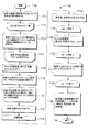
図11によれば、多格子信号変換による、ピクチャの位置適応的スパース性ベースのフィルタリング全体を参照符号1100で示す。図11の方法1100は、ディジタル画像の一連の再配置された整数格子サブサンプリングに対して、変換された領域においてスパース性ベースのフィルタリングを施すことに対応する。
Referring to FIG. 11,
方法1100は、開始ブロック1105を含み、開始ブロック1105は制御を関数ブロック1110に渡す。関数ブロック1110は、副格子画像分解の考えられるファミリーの形状及び数を設定し、制御をループ限度ループ1115に渡す。ループ限度ブロック1115は、変数jを使用して、(副)格子のファミリー毎のループを行い、制御を関数ブロック1120に渡す。関数ブロック1120は、画像をダウンサンプリングし、副格子jのファミリーに応じてN個の副格子に分離し(合計量は各ファミリーjに依存する)、制御をループ限度ブロック1125に渡す。ループ限度ブロック1125は、変数k(合計量はファミリーjに依存する)を使用して、副格子毎のループを行い、制御の関数ブロック1130に渡す。関数ブロック1130は、サンプルを(例えば、配置A(j.k)からBに)再配置し、制御を関数ブロック1135に渡す。関数ブロック1135は、副格子jの特定のファミリーについて使用することが許容される変換を選択し、制御をループ限度ブロック1140に渡す。ループ限度ブロック1140は、許容される変換(副格子jの副格子ファミリーに応じて選択される)毎のループを行い、制御を関数ブロック1145に渡す。関数ブロック945は、変換行列iによる変換を行い、制御を関数ブロック1150に渡す。関数ブロック1150は、係数を雑音除去し、制御を関数ブロック1155に渡す。関数ブロック1155は、逆変換行列iによる逆変換を行い、制御をループ限度ブロック1160に渡す。ループ限度ブロック1160は、変数iの各値にわたるループを終了し、制御を関数ブロック1165に渡す。関数ブロック1165は、サンプルを(配置BからA(j,k))に再配置し、制御をループ限度ブロック1170に渡す。ループ限度ブロック1170は変数kの各値にわたるループを終了し、制御を関数ブロック1175に渡す。関数1175は、副格子をアップサンプリングし、副格子jのファミリーに応じてマージし、制御をループ限度ブロック1180に渡す。ループ限度ブロック1180は変数jの各値にわたるループを終了し、制御を関数ブロック1185に渡す。関数ブロック1185は、雑音除去係数画像の別々の逆変換バージョン(の、例えば、局所適応的加重和)を合成し、制御を終了ブロック1199に渡す。
The
図11を参照すれば、一実施例では、一連のフィルタリングされたピクチャが、変換された領域のフィルタリング(同様に、ピクチャの別々のサブサンプリングにおける別々の変換を使用する)を使用することによって生成される。最終フィルタリング画像は、フィルタリングされたピクチャそれぞれの局所適応的加重和として計算される。 Referring to FIG. 11, in one embodiment, a series of filtered pictures are generated by using transformed domain filtering (also using separate transforms in separate subsamplings of the picture). Is done. The final filtered image is calculated as a locally adaptive weighted sum of each filtered picture.
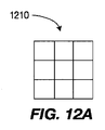
一実施例では、ディジタル画像の何れかの再配置された整数格子サブサンプリングに施された変換の組は、2D DCTの考えられる平行移動全てによって形成される。これは、ブロック変換の場合、ピクチャのブロック・ベースの区分のための、4×4DCTの合計16個の考えられる平行移動が存在していることを示唆している。同様に、64が、8×8のDCTの考えられる平行移動の合計数となる。この例は、図12A乃至図12Dで分かる。図12A及び図12Dに移れば、画像のDCT変換のためのブロック区分の例示的な考えられる平行移動全体を、参照符号1210、1220、1230及び1240それぞれで示す。図12乃至図12Dはそれぞれ、4×4DCT変換の16個の考えられる平行移動の4つのうちの1つを示す。変換サイズよりも小さい不完全境界ブロックは、例えば、特定のパディング又は画像拡張を使用して、事実上、拡張することが可能である。ピクチャの境界上の、変換サイズよりも小さな区分は、パディング又は特定の種類のピクチャ拡張によって事実上拡張することが可能である。これは、画像ブロック全てにおける同じ変換サイズの使用を可能にする。図11は、副格子それぞれに、本願の例における前述の平行移動DCTの組が施されるということを示す。
In one embodiment, the set of transforms applied to any rearranged integer grid subsampling of the digital image is formed by all possible translations of the 2D DCT. This suggests that in the case of block transforms, there are a total of 16 possible translations of 4 × 4 DCT for block-based partitioning of pictures. Similarly, 64 is the total number of possible translations of an 8 × 8 DCT. An example of this can be seen in FIGS. 12A-12D. Turning to FIGS. 12A and 12D, exemplary possible overall translations of block sections for DCT transformation of images are indicated by
一実施例では、フィルタリング処理は、全格子サブサンプリングの全平行移動変換の変換係数を閾値化し、選択し、かつ/又は重み付けすることにより、変換段階のコアにおいて行うことが可能である。前述の目的のために使用される閾値は、限定列挙でないが、局所信号特性、ユーザ選択、局所統計、大局統計、局所雑音、大局雑音、局所歪み、大局歪み、除去に予め指定された信号成分の統計、及び除去に予め所定された信号成分の特性のうちの1つ又は複数に依存し得る。閾値化工程後、変換され、かつ/又は平行移動された格子サブサンプリングは全て、逆変換される。相補的コセットの組は全て、元のサンプリング手法に戻され、元のピクチャの元のサンプリング・グリッドを回復するためにアップサンプリングされ、マージされる。変換が、ピクチャの元のサンプリングに直接施される特定の場合、回転、アップサンプリング、及びサンプル・マ―ジは必要でない。 In one embodiment, the filtering process can be performed at the core of the transform stage by thresholding, selecting and / or weighting the transform coefficients of all translation transforms of all grid subsampling. The thresholds used for the aforementioned purposes are not limited enumeration, but signal components pre-specified for local signal characteristics, user selection, local statistics, global statistics, local noise, global noise, local distortion, global distortion, removal , And one or more of the predetermined signal component characteristics for removal. After the thresholding step, all transformed and / or translated grid subsampling is inverse transformed. All complementary coset sets are returned to the original sampling approach, upsampled and merged to recover the original sampling grid of the original picture. In the specific case where the transformation is directly applied to the original sampling of the picture, rotation, upsampling, and sample merge are not required.
アーチファクト解除されたピクチャ推定の多格子多変換の組を融合させるための重み生成:
最後に、図11によれば、違ったふうにフィルタリングされたピクチャは全て、全ての重み付けられた加算により、一ピクチャに混合する。一実施例では、これは以下のやり方で行われる。I’iを、閾値化によってフィルタリングされる別々の画像それぞれとし、I’iはそれぞれ、フィルタリング処理中、格子サブサンプリングを受けているか、又は受けていないことがあり得るピクチャのDCT(又はMPEG−4AVC標準の整数変換)の特定の平行移動の閾値化後の、再構成されたピクチャの何れかに対応し得る。Wiを、I’iにおけるそのコロケートされた画素に関連付けられた重みを全画素が含む重みのピクチャとする。その場合、最終推定値I’finalは、
Finally, according to FIG. 11, all the differently filtered pictures are mixed into one picture with all weighted additions. In one embodiment, this is done in the following manner. Let I ′ i be each separate image that is filtered by thresholding, and each I ′ i is the DCT (or MPEG−) of a picture that may or may not have undergone grid subsampling during the filtering process. It can correspond to any of the reconstructed pictures after thresholding a certain translation of the 4AVC standard integer transform). Let W i be a picture of the weight that all pixels contain the weight associated with that collocated pixel in I ′ i . In that case, the final estimate I ′ final is
一実施例では、Wi(x,y)は、先行する式において使用された場合、全位置で、変換領域においてスパース性の局所の表現を有するI’i(x,y)が、より大きな重みを有するように計算される。閾値化後の、変換のうちの、より高スパース性の変換から得られるI’i(x,y)が、最低量の雑音/歪みを含むという前提からくる。一実施例では、Wi(x,y)行列が、全I’i(x,y)について生成される(サブサンプリングされていないフィルタリング、及び格子サブサンプリング・ベースのフィルタリングから得られる)。格子サブサンプリング手順を経た、I’i(x,y)に対応するWi(x,y)は、フィルタリングされたサブサンプル画像(すなわち、回転、アップサンプリング及びマージの前)毎の別個のWi,coset(j)(x,y)の生成によって得られ、次いで、I’i(x,y)に対応する別のWi,coset(j)(x,y)は、その相補的なサブサンプリングされた成分からI’i(x,y)を再分解するために行われるように回転させられ、アップサンプリングされ、マージされる。よって、一例では、フィルタリング処理中に5点形サブサンプリングを経た、フィルタリングされた画像は全て、2つの重みサブサンプリングされた行列を有する。これらは次いで、その対応するI’i(x,y)に使用する対象の1つの単一の重み付け行列に回転させ、アップサンプリングし、マージすることが可能である。 In one embodiment, W i (x, y) is larger when used in the preceding equation, with I ′ i (x, y) having a sparse local representation in the transform domain at all positions. Calculated to have a weight. It comes from the premise that I ′ i (x, y) resulting from the higher sparsity of the transformations after thresholding contains the least amount of noise / distortion. In one embodiment, a W i (x, y) matrix is generated for all I ′ i (x, y) (obtained from unsubsampled filtering and lattice subsampling based filtering). W i (x, y) corresponding to I ′ i (x, y), which has undergone the grid subsampling procedure, is a separate W for each filtered subsampled image (ie, before rotation, upsampling and merging). i, coset (j) (x, y) is then generated, and then another Wi, coset (j) (x, y) corresponding to I ′ i (x, y) is its complementary Rotated, upsampled and merged as done to re-decompose I ′ i (x, y) from the subsampled components. Thus, in one example, all filtered images that have undergone five-point subsampling during the filtering process have two weighted subsampled matrices. These can then be rotated, upsampled, and merged into one single weighting matrix of interest to use for its corresponding I ′ i (x, y).
一実施例では、各Wi,coset(j)(x,y)の生成は、Wi(x,y)と同様に行われる。各画素には、前述の画素が含まれるブロック変換の非ゼロ係数の量から得られる重みが割り当てられる。一例では、Wi,coset(j)(x,y)(及びWi(x,y))の重みは、画素それぞれを含むブロック変換内の非ゼロ係数の量と反比例するように画素毎に計算することが可能である。この手法では、Wi(x,y)における重みは、I’i(x,y)を生成するために使用される変換と同じブロック構造を有する。 In one embodiment, the generation of each W i, coset (j) (x, y) is performed in the same manner as W i (x, y). Each pixel is assigned a weight that is obtained from the amount of non-zero coefficients of the block transform that includes the aforementioned pixel. In one example, the weight of W i, coset (j) (x, y) (and W i (x, y)) is pixel by pixel so that it is inversely proportional to the amount of non-zero coefficients in the block transform that contains each pixel. It is possible to calculate. In this approach, the weights in W i (x, y) have the same block structure as the transform used to generate I ′ i (x, y).
サンプリング/サブサンプリング格子の変換の組の選択
DCT及び/又は整数MPEG−4AVC標準ブロック変換が、スパース性ベースのアーチファクト解除インループ・フィルタ内で使用される一実施例では、フィルタリング工程において使用される変換は、MPEG−4AVC標準における予測工程後の残差信号を符号化するために使用される変換と厳密に相似であるか(、又は等しい)。符号化信号に挿入される量子化誤差は時には、再構成に利用可能な係数の数の削減の形式下であるので、係数の前述の削減により、第1の従来技術手法における重みの生成において行われる信号スパース性の尺度が不明確になる。これにより、量子化雑音は、重み生成に影響を及ぼし、これは、次いで、一部の場所において、最善のI’iの適切な重み付けに影響を及ぼし、これにより、フィルタリング後に、一部のブロック状アーチファクトがなお目に見える。
Selection of Sampling / Subsampling Grid Transform Set In one embodiment where DCT and / or integer MPEG-4 AVC standard block transform is used in a sparseness-based de-artifact in-loop filter, it is used in the filtering step The transform is exactly similar (or equal) to the transform used to encode the post-prediction residual signal in the MPEG-4 AVC standard. Since the quantization error inserted into the encoded signal is sometimes in the form of a reduction in the number of coefficients available for reconstruction, the aforementioned reduction in the coefficients causes the first prior art technique to generate weights. The sparseness of signal sparsity is unclear. This causes quantization noise to affect weight generation, which in turn affects the appropriate weighting of the best I ′ i in some places, so that after filtering, some blocks -Like artifacts are still visible.
前述の通り、スパース性ベースのフィルタリングに関する前提の1つは、真の信号が、変換及びサブサンプリング格子のうちの少なくとも1つにおけるスパース性表現/近似を有し、信号のアーチファクト成分は、変換及びサブサンプリング格子のうちの何れかにおけるスパース性表現/近似を有しないという点である。すなわち、アーチファクト信号がその部分空間から概ね排除されるか、又は影響力が低い状態で存在する一方で、基底関数の部分空間内で真の(所望の信号)をうまく近似することが可能であるということが期待される。 As mentioned above, one of the assumptions regarding sparsity-based filtering is that the true signal has a sparsity representation / approximation in at least one of the transform and subsampling grids, and the artifact component of the signal is transformed and It does not have a sparse representation / approximation in any of the subsampling grids. That is, it is possible to approximate the true (desired signal) well within the subspace of the basis function while the artifact signal is largely excluded from the subspace or exists in a low-impact state That is expected.
符号化変換ブロックとアラインされた、又はほぼアラインされた(例えば、x方向及びy方向のうちの少なくとも一方における1画素のミスアラインメント)フィルタリング変換ブロックについて、フィルタリングのために、かつ残差符号化のために同じ変換ファミリーを使用する場合、信号内にもたらされる量子化雑音及び/アーチファクトは、ほとんど、信号自体として基底関数の同じ部分空間内に収まる。その場合、雑音除去アルゴリズムにより、信号及び雑音が不明確になりやすくなり(すなわち、雑音は、信号に対する無相関均質分布(i.i.d.)でなく)、通常、それらを分離することが可能でない。予測
Ipred(x,y)、及び直交変換(すなわち、この場合、MPEG−4AVC整数変換)を以下のように使用した変換残差信号Ires(x,y)=Iorg(x,y)−Ipred(x,y)により、元の信号Iorg(x,y)のMPEG−4AVC標準による以下の式を検討する:
For filtering transform blocks that are aligned or nearly aligned with the coding transform block (eg, one pixel misalignment in at least one of the x and y directions) for filtering and for residual coding In order to use the same family of transformations, the quantization noise and / or artifacts introduced in the signal mostly fall within the same subspace of the basis function as the signal itself. In that case, the denoising algorithm tends to obscure the signal and noise (ie, the noise is not an uncorrelated homogenous distribution (iid) to the signal) and can usually separate them. Not possible. Transform residual signal I res (x, y) = I org (x, y) using prediction I pred (x, y) and orthogonal transform (ie, MPEG-4 AVC integer transform in this case) as follows: With -I pred (x, y), consider the following equation from the MPEG-4 AVC standard for the original signal I org (x, y):
![]()
![]()
量子化工程では、変換
量子化による残差の非ゼロ係数の数における減少は、例えば、非ゼロ係数の数に影響を及ぼし、それは、Iorig(x,y)よりもスパース性が高い表現を有する信号につながり得る。雑音除去アルゴリウズムが施されると、符号化変換によって使用されるブロック区分とより高いアラインメントを有する、非サブサンプル格子における変換はおそらく、表す信号が係数の点でよりコンパクトであるということを見出すであろう。前述の重み生成方法によれば、「アラインされた」変換から生じるフィルタリングされたピクチャが好まれ、アーチファクトは信号内に残ってしまう。「アラインされた」、又はかなり「アラインされた」)(例えば、x方向及びy方向のうちの少なくとも一方における1画素のアラインメントを使用する)前述のフィルタリング工程は、アーチファクト信号と「真の」信号とを分離することができない。 A reduction in the number of non-zero coefficients of the residual due to quantization affects, for example, the number of non-zero coefficients, which can lead to signals having a sparser representation than I orig (x, y). Once the denoising algorithm is applied, the transformation in the non-subsampled grid, which has a higher alignment with the block partition used by the coding transformation, will probably find that the signal it represents is more compact in terms of coefficients. I will. According to the weight generation method described above, filtered pictures resulting from “aligned” transformations are preferred, and artifacts remain in the signal. The above-described filtering step (e.g., using a one pixel alignment in at least one of the x and y directions) is an "aligned" or fairly "aligned") artifact signal and "true" signal. And cannot be separated.
これに基づいて、サンプリングされた格子それぞれにおいて使用される変換の組は、符号化変換と「アライン」又はかなり「アライン」されたフィルタリング変換が存在しないように適応させる。一実施例では、これは、サブサンプリングされていない格子において使用される変換に影響を及ぼす(すなわち、フィルタリングするための、歪んだピクチャへの平行移動変換の直接適用)。 Based on this, the set of transforms used in each of the sampled grids is adapted so that there are no encoding transforms and “aligned” or significantly “aligned” filtering transforms. In one embodiment, this affects the transform used in the unsubsampled grid (ie, direct application of the translation transform to the distorted picture for filtering).
一実施例では、フィルタリングの目的でDCT(及び/又はMPEG−4 AVC標準整数変換)の種々の平行移動(又は平行移動の組)を使用することを検討する。4×4変換が使用される場合、16個の考えられる変換を、使用される行列の組の一部とみなし得る。平行移動(0,0)が、残差を符号化するためのMPEG−4 AVC標準工程のブロック区分であるとした場合、例えば、ブロック軸のうちの少なくとも1つとアラインされた平行移動は除去しなければならないことがあり得る。一実施例では、DCT(及び/又はMPEG−4 AVC標準整数変換)の
平行移動
(0,0)、(0,1)、(0,2)、(0,3)、(1,0)、(2,0)及び(3,0)
である変換は、ピクチャのサブサンプリングされない格子に対する使用される変換の組から除外される。
In one embodiment, consider using various translations (or sets of translations) of DCT (and / or MPEG-4 AVC standard integer transform) for filtering purposes. If a 4x4 transform is used, the 16 possible transforms can be considered part of the set of matrices used. If the translation (0,0) is a block segment of the MPEG-4 AVC standard process for encoding residuals, for example, translations aligned with at least one of the block axes are removed. It may be necessary. In one embodiment, DCT (and / or MPEG-4 AVC standard integer transform) translations (0,0), (0,1), (0,2), (0,3), (1,0) , (2,0) and (3,0)
Is removed from the set of transforms used for the unsubsampled lattice of the picture.
これは、ブロック軸両方において少なくとも平行移動された変換の平行移動のみが、この例において実際に使用されるということを意味している。例えば、平行移動は、図12A乃至図12Dに示す考えられる平行移動の組から得ることができ、3つ目(図12C、左下)のみが考慮に入れられる。 This means that only translational translations that are translated at least in both block axes are actually used in this example. For example, the translation can be obtained from the possible translation set shown in FIGS. 12A-12D, and only the third (FIG. 12C, lower left) is taken into account.
一実施例では、DCT(又はMPEG−4 AVC標準整数変換)の考えられる平行移動全てが、5点形サンプリングに対する変換について考慮に入れられる。 In one embodiment, all possible translations of DCT (or MPEG-4 AVC Standard Integer Transform) are taken into account for the transformation for 5-point sampling.
インループ・フィルタ適応:
本明細書及び特許請求の範囲に記載された、本願において提案するアーチファクト解除アルゴリズムは、インループ・アーチファクト解除フィルタ内で使用するために組み込むことができる。本願提案のインループ・アーチファクト解除フィルタは、ハイブリッド・ビデオ符号化器/復号化器のループ内に、又は符号化器及び/若しくは復号化器の別個の実現形態内に組み込むことができる。ビデオ符号化器/復号化器は例えば、MPEG−4AVC標準ビデオ符号化器/復号化器であり得る。図5及び図6は、例示的な実施例を示す。前述の実施例では、インループ・アーチファクト解除フィルタが、デブロッキング・フィルタに代わりに、MPEG−4AVC標準符号化器及び復号化器それぞれに挿入されている(比較のために図3及び図4を参照されたい)。
In-loop filter adaptation:
The proposed de-artifact algorithm described herein and in the claims can be incorporated for use in an in-loop de-artifact filter. The proposed in-loop de-artifact filter can be incorporated in the loop of the hybrid video encoder / decoder or in a separate implementation of the encoder and / or decoder. The video encoder / decoder may be, for example, an MPEG-4 AVC standard video encoder / decoder. 5 and 6 show an exemplary embodiment. In the previous embodiment, an in-loop artifact removal filter is inserted in each of the MPEG-4 AVC standard encoder and decoder instead of the deblocking filter (for comparison purposes, see FIGS. 3 and 4). See).
図13に移れば、多格子スパース性フィルタリングに基づいた例示的なインループ・アーチファクト解除フィルタ全体を参照符号1300で示す。
Turning to FIG. 13, an exemplary in-loop artifact removal filter based on multi-grid sparsity filtering is indicated generally by the
フィルタ1300は、画素マスキング・モジュール1320の第1の入力と信号通信で接続された出力を有する適応的スパース性ベースのフィルタ(多格子信号変換を有する)1310を含む。閾値生成器1330の出力は、適応的スパース性ベースのフィルタ1310の第1の入力と信号通信で接続される。
適応的スパース性フィルタ1310の第2の入力及び画素マスキング・モジュール1320の第2の入力は、入力ピクチャを受信するために、フィルタ1300の入力として利用可能である。閾値生成器1330の入力、適応的スパース性ベースのフィルタ1310の第3の入力、及び画素マスキング・モジュール1320の第3の入力は、制御データを受信するために、フィルタ1300の入力として利用可能である。画素マスキング・モジュール1320の出力は、アーチファクト解除されたピクチャを出力するために、フィルタ1300の出力として利用可能である。
The second input of
閾値生成器1330は、ブロック変換それぞれの閾値を適応的に(例えば、平行移動及び/又は格子サブサンプリングそれぞれにおけるブロック毎に)計算する。前述の閾値は、(例えば、MPEG−4 AVC標準における量子化パラメータ(QP)を使用した)ブロック品質パラメータ、ブロック・モード、予測データ(イントラ予測モード、動きデータ等)、変換係数、局所信号構造、及び/又は局所信号統計のうちの少なくとも1つに依存する。一実施例では、ブロック変換毎のアーチファクト解除の閾値は、MPEG―4AVC標準のデブロッキング・フィルタリング強度に近い局所フィルタリング強度パラメータ、及びQPに局所に依存させることが可能である。
The
画素マスキング・モジュール1320は、ブロック品質パラメータ(例えば、MPEG−4AVC標準におけるQP)、ブロック・モード、予測データ(イントラ予測モード、動きデータ等)、変換係数、局所信号構造及び/又は局所信号統計のうちの少なくとも1つの関数に依存し、出力ピクチャの画素を、フィルタリングしていない状態のままにするか否か(よって、元のフィルタリング前画素が使用されるか、又はフィルタリングされた画素が使用されるか)を判定する。これは、変換係数が送信されていない符号化モード、又はアーチファクト解除フィルタリングが必要でない符号化モードにおいて特に有用である。前述のモードの例には、MPEG−4AVC標準におけるSKIPモードがある。
The
閾値生成器1330及び画素マスキング・モジュール1320は共に、図5及び図6それぞれに示す符号化制御装置505及び復号化制御装置605からの情報を使用する。
Both the
図5及び図6に示すように、符号化制御装置505及び復号化制御装置605は、提案されたインループ・アーチファクト解除フィルタの制御に対応するために修正される。これは、最も効率的な動作のためにインループ・アーチファクト解除フィルタを設定し、構成し、適応させるためのブロック・レベル構文及び高位構文の考えられる要件に影響する。実際に、アーチファクト解除フィルタは、ビデオ系列を符号化するためにオン又はオフに切り換えることができる。更に、いくつかのカスタム設定が、このデフォールト設定の特定の制御を有するために望ましいことがあり得る。この目的で、いくつかの構文フィールドを、限定列挙でないが、シーケンス・パラメータ・レベル、ピクチャ・パラメータ・レベル、スライス・レベル、及び/又はブロック・レベルを含む別々のレベルで定義することができる。以下では、いくつかの例示的なブロック及び/又は高位構文レベルのフィールドが、表1乃至3に表す対応する符号化構造によって表される。
As shown in FIGS. 5 and 6, the
表1は、多格子スパース性ベースのフィルタリングに基づくインループ・アーチファクト解除フィルタの例示的なピクチャ・パラメータ・セット構文データを示す。表2は、多格子スパース性ベースのフィルタリングに基づくインループ・アーチファクト解除フィルタの例示的なスライス・ヘッダ構文データを示す。表3は、多格子スパース性ベースのフィルタリングに基づくインループ・アーチファクト解除フィルタの例示的なマクロブロック構文データを示す。 Table 1 shows exemplary picture parameter set syntax data for an in-loop de-artifact filter based on multi-grid sparsity-based filtering. Table 2 shows exemplary slice header syntax data for an in-loop de-artifact filter based on multi-grid sparsity-based filtering. Table 3 shows exemplary macroblock syntax data for an in-loop de-artifact filter based on multi-grid sparsity-based filtering.
sparse_filter_control_present_flagが1に等しいことは、スパース性雑音除去フィルタの特性を制御する構文要素の組がスライス・ヘッダに存在しているということを示す。sparse_filter_control_present_flagが0に等しいことは、スパース性雑音除去フィルタの特性を制御する構文要素の組がスライス・ヘッダに存在しておらず、その推定値が実施されているということを示す
enable_selection_of_sparse_threshold、
enable_selection_of_transform_type、
enable_selection_of_adaptive_weighting_type、
enable_selection_of_set_of_subsampling_lattices及び
enable_selection_of_transform_setsは、例えば、シーケンス・パラメータ・セット・レベル及び/又はピクチャ・パラメータ・セット・レベルに配置され得る。一実施例では、前述の値は、閾値、変換タイプ、重み付けタイプ、スライス・レベルにおける格子毎の変換の組、及び/又は、サブサンプリング格子の組のデフォールト値を変更できることを可能にする。
A sparse_filter_control_present_flag equal to 1 indicates that a set of syntax elements that control the characteristics of the sparse denoising filter is present in the slice header. If the sparse_filter_control_present_flag is equal to 0, an enable_selection_of_sparse_threshold, which indicates that the set of syntax elements that control the characteristics of the sparse denoising filter is not present in the slice header and that the estimate is being implemented,
enable_selection_of_transform_type,
enable_selection_of_adaptive_weighting_type,
enable_selection_of_set_of_subsampling_lattices and enable_selection_of_transform_sets may be located, for example, at the sequence parameter set level and / or the picture parameter set level. In one embodiment, the aforementioned values allow the default values of the threshold, transform type, weighting type, per-grid transform set at the slice level, and / or the sub-sampling grid set to be changed.
disable_sparse_filter_flagは、スパース性雑音除去フィルタの動作をディセーブルするか否かを規定する。disable_sparse_filter_flagがスライス・ヘッダに存在していない場合、disable_sparse_filter_flagは0に等しいと推定する。 disable_sparse_filter_flag specifies whether or not to disable the operation of the sparse noise removal filter. If disable_sparse_filter_flag is not present in the slice header, it is assumed that disable_sparse_filter_flag is equal to zero.
sparse_thresholdは、スパース性雑音除去に使用された閾値の値を規定する。sparse_thresholdがスライス・ヘッダに存在していない場合、スライスQPに基づいて導き出されるデフォールト値が使用される。 sparse_threshold defines the threshold value used for sparse noise removal. If sparse_threshold is not present in the slice header, a default value derived based on the slice QP is used.
sparse_transform_typeは、スパース性雑音除去に使用される変換のタイプを規定する。sparse_transform_typeが0に等しいことは、4x4変換を使用するということを規定する。sparse_transform_typeが1に等しいことは、8x8変換を使用するということを規定する。 sparse_transform_type specifies the type of transform used for sparse denoising. A sparse_transform_type equal to 0 specifies that a 4x4 transform is used. A sparse_transform_type equal to 1 specifies that an 8x8 transform is used.
adaptive_weighting_typeは、スパース性雑音除去において使用される重み付けのタイプを規定する。例えば、adaptive_weighting_typeが0に等しいということは、スパース性重み付けが使用されるということを規定し得る。例えば、adaptive_weighting_typeが1に等しいということは、平均重み付けが使用されるということを規定し得る。 adaptive_weighting_type specifies the type of weighting used in sparse denoising. For example, an adaptive_weighting_type equal to 0 may specify that sparsity weighting is used. For example, an adaptive_weighting_type equal to 1 may specify that average weighting is used.
set_of_subsampling_latticesは、その変換に先行してピクチャを分解するために使用される、サブサンプリング格子の数、及びサブサンプリング格子を規定する。 set_of_subsampling_lattices specifies the number of subsampling grids and the subsampling grids used to decompose the picture prior to its transformation.
enable_macroblock_threshold_adaptation_flagは、閾値をマクロブロック・レベルで補正し、修正するか否かを規定する。 enable_macroblock_threshold_adaptation_flag specifies whether the threshold is corrected and corrected at the macroblock level.
transform_set_type[i]は、各格子サンプリングに使用される変換の組を、必要な場合、規定する。例えば、一実施例では、デフォールトと別の設定が必要な場合、格子サンプリングそれぞれにおけるインループ・フィルタリングに使用される変換の平行移動の組を符号化するために使用することが可能である。 transform_set_type [i] defines the set of transforms used for each grid sampling, if necessary. For example, in one embodiment, if different settings than the default are needed, it can be used to encode a translation set of transforms used for in-loop filtering in each of the lattice samplings.
sparse_threshold_deltaは、マクロブロックの(例えば、少なくとも50%の)実質的に重なるブロック変換において使用する対象の新たな閾値を規定する。新たな閾値は、GP、符号化された変換係数、及び/又はブロック符号化モードに応じて設定することができるデフォールト閾値に対する差、先行するマクロブロック閾値に対する差、及び/又はその完全値によって規定することができる。 sparse_threshold_delta defines a new threshold to be used in block transforms that substantially overlap (eg, at least 50%) of the macroblock. The new threshold is defined by the difference to the default threshold that can be set according to the GP, the encoded transform coefficient, and / or the block coding mode, the difference to the preceding macroblock threshold, and / or its full value. can do.
別の利点/特徴は、前述のインループ・アーチファクト解除フィルタを備えた符号化器を有する装置であり、ピクチャ・データは係数に変換され、インループ・アーチファクト解除フィルタは、信号スパ―ス性に基づいて変換領域における係数をフィルタリングする。 Another advantage / feature is an apparatus having an encoder with an in-loop de-artifact filter as described above, where picture data is converted to coefficients, and the in-loop de-artifact filter is Based on this, the coefficients in the transform domain are filtered.
更に別の利点/特徴は、前述の信号スパース性に基づいて、変換された領域において係数をフィルタリングするインループ・アーチファクト解除フィルタを備えた符号化器を有し、係数が、変換された領域において、ユーザ選択、局所信号特性、大局信号特性、局所信号統計、大局信号統計、局所歪み、大局歪み、局所雑音、大局雑音、除去に予め指定された信号成分の統計、除去に予め設定された信号成分の特性、ブロック符号化コード、及び係数のうちの少なくとも1つに応じた、局所適応性を有する少なくとも1つの閾値を使用して変換領域においてフィルタリングされる。 Yet another advantage / feature is to have an encoder with an in-loop artifact removal filter that filters coefficients in the transformed domain based on the signal sparsity described above, where the coefficients are in the transformed domain. , User selection, local signal characteristics, global signal characteristics, local signal statistics, global signal statistics, local distortion, global distortion, local noise, global noise, statistics of signal components specified in advance for removal, signals preset for removal Filtered in the transform domain using at least one threshold having local adaptability, depending on at least one of the component characteristics, block coding codes, and coefficients.
更に別の利点/特徴は、前述の信号スパース性に基づいて、変換された領域において係数をフィルタリングするインループ・アーチファクト解除フィルタを備えた符号化器を有し、係数が、変換された領域において、ユーザ選択、局所信号特性、大局信号特性、局所信号統計、大局信号統計、局所歪み、大局歪み、局所雑音、大局雑音、除去に予め指定された信号成分の統計、除去に予め設定された信号成分の特性、ブロック符号化コード、及び係数のうちの少なくとも1つに応じて、符号化器に対して局所に選択的にイネーブルされるか又はディセーブルされる。 Yet another advantage / feature is to have an encoder with an in-loop artifact removal filter that filters coefficients in the transformed domain based on the signal sparsity described above, where the coefficients are in the transformed domain. , User selection, local signal characteristics, global signal characteristics, local signal statistics, global signal statistics, local distortion, global distortion, local noise, global noise, statistics of signal components specified in advance for removal, signals preset for removal Depending on at least one of the component characteristics, the block coding code, and the coefficients, it is selectively selectively enabled or disabled locally for the encoder.
更に、別の利点/特徴は、前述の通り、インループ・アーチファクト解除フィルタを備えた符号化器を有する装置であり、インループ・アーチファクト除去フィルタの適用は、高位構文要素を使用して選択にイネーブルされるか、又はディセーブルされ、インループ・アーチファクト解除フィルタは、符号化器による適応、修正、及びイネーブル、及びディセーブルのうちの少なくとも1つにかけられ、適応、修正、イネーブル、及びディセーブルは、高位構文要素及びブロック・レベル構文要素の少なくとも一方を使用して、対応する復号化器に通知される。 Yet another advantage / feature is the apparatus having an encoder with an in-loop artifact removal filter, as described above, and the application of the in-loop artifact removal filter can be selected using high-level syntax elements. Enabled or disabled, the in-loop de-artifact filter is subjected to at least one of adaptation, modification, and enable and disable by the encoder to adapt, modify, enable, and disable Is signaled to the corresponding decoder using at least one of a high level syntax element and a block level syntax element.
更に、別の利点/特徴は、上述のインループ・アーチファクト解除フィルタを備えた符号化器を有する装置であり、インループ・アーチファクト解除フィルタは、バージョン生成器、重み算出器、及び合成器を含む。バージョン生成器は、ピクチャの少なくとも2つのフィルタリングされたバージョンを生成する。重み算出器は、ピクチャの少なくとも2つのフィルタリングされたバージョンそれぞれの重みを算出する。合成器は、ピクチャの少なくとも2つのフィルタリングされたバージョンの適応的に重み付けられた組合せを適応的に算出する。 Yet another advantage / feature is an apparatus having an encoder with an in-loop artifact removal filter as described above, wherein the in-loop artifact removal filter includes a version generator, a weight calculator, and a combiner. . The version generator generates at least two filtered versions of the picture. The weight calculator calculates the weight of each of the at least two filtered versions of the picture. The synthesizer adaptively calculates an adaptively weighted combination of at least two filtered versions of the picture.
本願の原理の前述並びに他の特徴及び利点は、本明細書及び特許請求の範囲記載の教示に基づいて、当業者が容易に確かめることができる。本願の原理の教示は、種々の形態のハードウェア、ソフトウェア、ファームウェア、特殊用途向プロセッサ、又はそれらの組み合わせで実現することができる。 The foregoing and other features and advantages of the present principles may be readily ascertained by one skilled in the art based on the teachings contained herein and the claims. The teachings of the present principles may be implemented in various forms of hardware, software, firmware, special purpose processors, or combinations thereof.
最も好ましくは、本願の原理の教示は、ハードウェア及びソフトウェアの組合せとして実現される。更に、ソフトウェアは、プログラム記憶装置上に有形に実施されたアプリケーション・プログラムとして実現することができる。アプリケーション・プログラムは、何れかの適切なアーキテクチャを有するマシンにアップロードし、前述のマシンによって実行することができる。好ましくは、マシンは、1つ又は複数の中央処理装置(「CPU」)、ランダム・アクセス・メモリ(「RAM」)や、入出力(「I/O」)インタフェースなどのハードウェアを有するコンピュータ・プラットフォーム上に実現される。コンピュータ・プラットフォームは、オペレーティング・システム及びマイクロ命令コードも含み得る。本明細書及び特許請求の範囲記載の種々の処理及び機能は、CPUによって実行することができるアプリケーション・プログラムの一部若しくはマイクロ命令コードの一部(又はそれらの組み合わせ)であり得る。更に、種々の他の周辺装置を、更なるデータ記憶装置や、印刷装置などのコンピュータ・プラットフォームに接続することができる。 Most preferably, the teachings of the present principles are implemented as a combination of hardware and software. Furthermore, the software can be realized as an application program tangibly implemented on a program storage device. The application program can be uploaded to a machine having any suitable architecture and executed by the machine described above. Preferably, the machine is a computer computer having hardware such as one or more central processing units (“CPU”), random access memory (“RAM”), and input / output (“I / O”) interfaces. Realized on the platform. The computer platform may also include an operating system and microinstruction code. The various processes and functions described herein may be part of an application program or part of microinstruction code (or a combination thereof) that can be executed by a CPU. In addition, various other peripheral devices can be connected to the computer platform such as an additional data storage device and a printing device.
添付図面に表す構成システム部分及び方法の一部は好ましくはソフトウェアで実現されるので、システム部分(又は処理機能ブロック)間の実際の接続は、本願の原理がプログラムされるやり方によって変わり得る。本明細書及び特許請求の範囲記載の教示があれば、当業者は、本願の原理の前述及び同様な実現形態又は構成に想到することができるであろう。 Since some of the constituent system portions and methods depicted in the accompanying drawings are preferably implemented in software, the actual connections between system portions (or processing function blocks) may vary depending on how the principles of the present application are programmed. Given the teachings herein, one of ordinary skill in the related art will be able to contemplate these and similar implementations or configurations of the present principles.
例証的な実施例は、添付図面を参照して本明細書において説明してきたが、本願の原理は前述のまさにその実施例に限定されず、種々の変更及び修正を、本願の原理の範囲又は趣旨から逸脱することなく、当業者によって行うことができる。前述の変更及び修正は全て、特許請求の範囲記載の本願の原理の範囲内に含まれることが意図されている。 While illustrative embodiments have been described herein with reference to the accompanying drawings, the principles of the present application are not limited to the exact embodiments described above, and various changes and modifications may be made within the scope of the present principles or This can be done by those skilled in the art without departing from the spirit. All such changes and modifications are intended to be included within the scope of the present claimed invention.
Claims (12)
ピクチャのピクチャ・データを符号化する符号化器
を備え、
前記符号化器は、
符号化され、次いで復号化されたピクチャをアーチファクト解除するインループ・アーチファクト解除フィルタ
を含み、前記アーチファクト解除フィルタは、
前記復号化されたピクチャのサブサンプリングを生成するよう前記復号化されたピクチャをダウンサンプリングするダウンサンプリング・モジュールと、
前記復号化されたピクチャ及び前記サブサンプリングから前記復号化されたピクチャのフィルタリングされた少なくとも2つのバージョンを生成するバージョン生成器と、
前記フィルタリングされた少なくとも2つのバージョンそれぞれの重みを算出する重み算出器と、
前記フィルタリングされた少なくとも2つのバージョンの適応的に重み付けされた組合せを算出する合成器と
を含む装置。 A device,
An encoder for encoding picture data of a picture;
The encoder is
An in-loop de-artifact filter that de-artifacts the encoded and then decoded pictures, the de-artifact filter comprising:
And downsampling module for downsampling the decoded picture to generate a sub-sampling of the decrypted by picture,
A version generator for generating at least two filtered versions of the decoded picture from the decoded picture and the sub-sampling;
A weight calculator for calculating a weight for each of the filtered at least two versions;
A synthesizer for calculating an adaptively weighted combination of the filtered at least two versions.
ピクチャのピクチャ・データを、符号化器が符号化する工程
を含み、
前記符号化する工程は、
符号化され、次いで、復号化されたピクチャを、インループ・アーチファクト解除フィルタがインループ・アーチファクト解除フィルタリングする工程を含み、前記アーチファクト解除フィルタリングする工程は、
前記復号化されたピクチャのサブサンプリングを生成するよう前記復号化されたピクチャを、ダウンサンプリング・モジュールがダウンサンプリングする工程と、
前記復号化されたピクチャ及び前記サブサンプリングから前記復号化されたピクチャのフィルタリングされた少なくとも2つのバージョンを、バージョン生成器が生成する工程と、
前記フィルタリングされた少なくとも2つのバージョンそれぞれの重みを、重み算出器が算出する工程と、
前記フィルタリングされた少なくとも2つのバージョンの適応的に重み付けされた組合せを、合成器が算出する工程と
を含む方法。 A method,
The picture data of the picture, the encoder includes a step of encoding,
The encoding step includes:
Coded, then, the decoded picture, comprises the in-loop artifact cancellation filter in-loop artifact cancellation filtering to process the artifact cancellation filtering to process,
The decoded picture to generate a sub-sampling of the decoded picture, a step of downsampling module downsampling,
The filtered least two versions of the picture which is the decoded from the decoded picture and the sub-sampling, and generating version generator,
The weight of each of at least two versions is the filtered, a step of weighting calculator calculates,
Method comprising the step of adaptively weighted combination of at least two versions which are the filtered, synthesizer is calculated.
ピクチャのピクチャ・データを復号化する復号化器を備え、
前記復号化器は、
復号化されたピクチャをアーチファクト解除するインループ・アーチファクト解除フィルタ
を含み、前記アーチファクト解除フィルタは、
前記復号化されたピクチャのサブサンプリングを生成するよう前記復号化されたピクチャをダウンサンプリングするダウンサンプリング・モジュールと、
前記復号化されたピクチャ及び前記サブサンプリングから前記復号化されたピクチャのフィルタリングされた少なくとも2つのバージョンを生成するバージョン生成器と、
前記フィルタリングされた少なくとも2つのバージョンそれぞれの重みを算出する重み算出器と、
前記フィルタリングされた少なくとも2つのバージョンの適応的に重み付けされた組合せを算出する合成器と
を含む装置。 A device,
A decoder for decoding picture data of a picture;
The decoder is
An in-loop de-artifact filter for de-artifacting the decoded picture, the de-artifact filter comprising:
A downsampling module for downsampling the decoded picture to generate a subsampling of the decoded picture;
A version generator for generating at least two filtered versions of the decoded picture from the decoded picture and the sub-sampling;
A weight calculator for calculating a weight for each of the filtered at least two versions;
A synthesizer for calculating an adaptively weighted combination of the filtered at least two versions.
ピクチャのピクチャ・データを、復号化器が復号化する工程
を含み、
前記復号化する工程は、
復号化されたピクチャを、インループ・アーチファクト解除フィルタがインループ・アーチファクト解除フィルタリングする工程を含み、前記アーチファクト解除フィルタリングする工程は、
前記復号化されたピクチャのサブサンプリングを生成するよう前記復号化されたピクチャを、ダウンサンプリング・モジュールがダウンサンプリングする工程と、
前記復号化されたピクチャ及び前記サブサンプリングから前記復号化されたピクチャのフィルタリングされた少なくとも2つのバージョンを生成する工程と、
前記フィルタリングされた少なくとも2つのバージョンそれぞれの重みを算出する工程と、
前記フィルタリングされた少なくとも2つのバージョンの適応的に重み付けされた組合せを算出する工程と
を含む方法。 A method,
The picture data of the picture, comprising the step of decoder to decrypt,
The decrypting step includes:
The decoded picture includes an in-loop artifact removal filter by an in-loop artifact removal filter, wherein the artifact removal filtering comprises:
The decoded picture to generate a sub-sampling of the decoded picture, a step of downsampling module downsampling,
Generating at least two filtered versions of the decoded picture from the decoded picture and the sub-sampling;
Calculating a weight for each of the filtered at least two versions;
Calculating an adaptively weighted combination of the filtered at least two versions.
Applications Claiming Priority (3)
| Application Number | Priority Date | Filing Date | Title |
|---|---|---|---|
| US94268607P | 2007-06-08 | 2007-06-08 | |
| US60/942,686 | 2007-06-08 | ||
| PCT/US2008/006971 WO2008153856A1 (en) | 2007-06-08 | 2008-06-03 | Methods and apparatus for in-loop de-artifacting filtering based on multi-lattice sparsity-based filtering |
Publications (3)
| Publication Number | Publication Date |
|---|---|
| JP2010529777A JP2010529777A (en) | 2010-08-26 |
| JP2010529777A5 JP2010529777A5 (en) | 2011-07-21 |
| JP5345139B2 true JP5345139B2 (en) | 2013-11-20 |
Family
ID=39847062
Family Applications (1)
| Application Number | Title | Priority Date | Filing Date |
|---|---|---|---|
| JP2010511169A Active JP5345139B2 (en) | 2007-06-08 | 2008-06-03 | Method and apparatus for in-loop de-artifact filtering based on multi-grid sparsity-based filtering |
Country Status (7)
| Country | Link |
|---|---|
| US (1) | US20100128803A1 (en) |
| EP (1) | EP2160901A1 (en) |
| JP (1) | JP5345139B2 (en) |
| KR (1) | KR101554906B1 (en) |
| CN (1) | CN101779464B (en) |
| BR (1) | BRPI0812190A2 (en) |
| WO (1) | WO2008153856A1 (en) |
Families Citing this family (33)
| Publication number | Priority date | Publication date | Assignee | Title |
|---|---|---|---|---|
| US7724827B2 (en) | 2003-09-07 | 2010-05-25 | Microsoft Corporation | Multi-layer run level encoding and decoding |
| EP2229782A2 (en) * | 2008-01-14 | 2010-09-22 | Thomson Licensing | Methods and apparatus for de-artifact filtering using multi-lattice sparsity-based filtering |
| EP2351374A1 (en) * | 2008-11-25 | 2011-08-03 | Thomson Licensing | Methods and apparatus for sparsity-based de-artifact filtering for video encoding and decoding |
| BRPI1007869B1 (en) * | 2009-03-12 | 2021-08-31 | Interdigital Madison Patent Holdings | METHODS, APPARATUS AND COMPUTER-READABLE STORAGE MEDIA FOR REGION-BASED FILTER PARAMETER SELECTION FOR ARTIFACT REMOVAL FILTERING |
| US9020287B2 (en) * | 2009-04-14 | 2015-04-28 | Thomson Licensing | Methods and apparatus for filter parameter determination and selection responsive to variable transforms in sparsity-based de-artifact filtering |
| JP5604825B2 (en) * | 2009-08-19 | 2014-10-15 | ソニー株式会社 | Image processing apparatus and method |
| JP2011151431A (en) | 2009-12-25 | 2011-08-04 | Sony Corp | Image processing apparatus and method |
| EP2596635B1 (en) * | 2010-07-19 | 2020-05-20 | Dolby Laboratories Licensing Corporation | Enhancement methods for sampled and multiplexed image and video data |
| CN102377993B (en) * | 2010-08-05 | 2014-09-03 | 富士通株式会社 | Intra-frame prediction mode selection method and system |
| WO2012029181A1 (en) * | 2010-09-03 | 2012-03-08 | 株式会社 東芝 | Video encoding method and decoding method, encoding device and decoding device |
| US8787443B2 (en) * | 2010-10-05 | 2014-07-22 | Microsoft Corporation | Content adaptive deblocking during video encoding and decoding |
| GB2484969B (en) * | 2010-10-29 | 2013-11-20 | Canon Kk | Improved reference frame for video encoding and decoding |
| US10244239B2 (en) | 2010-12-28 | 2019-03-26 | Dolby Laboratories Licensing Corporation | Parameter set for picture segmentation |
| US20120183078A1 (en) * | 2011-01-14 | 2012-07-19 | Samsung Electronics Co., Ltd. | Filter adaptation with directional features for video/image coding |
| US9001883B2 (en) | 2011-02-16 | 2015-04-07 | Mediatek Inc | Method and apparatus for slice common information sharing |
| US9042458B2 (en) | 2011-04-01 | 2015-05-26 | Microsoft Technology Licensing, Llc | Multi-threaded implementations of deblock filtering |
| WO2012169054A1 (en) * | 2011-06-09 | 2012-12-13 | 株式会社東芝 | Video coding method and device, and video decoding method and device |
| US9942573B2 (en) * | 2011-06-22 | 2018-04-10 | Texas Instruments Incorporated | Systems and methods for reducing blocking artifacts |
| US9313497B2 (en) * | 2012-01-25 | 2016-04-12 | Intel Corporation | Systems, methods, and computer program products for transform coefficient sub-sampling |
| US9584805B2 (en) * | 2012-06-08 | 2017-02-28 | Qualcomm Incorporated | Prediction mode information downsampling in enhanced layer coding |
| US20140072048A1 (en) * | 2012-09-13 | 2014-03-13 | Samsung Electronics Co., Ltd | Method and apparatus for a switchable de-ringing filter for image/video coding |
| GB2509703B (en) * | 2013-01-04 | 2016-09-14 | Canon Kk | Method and apparatus for encoding an image into a video bitstream and decoding corresponding video bitstream using enhanced inter layer residual prediction |
| US9451254B2 (en) | 2013-07-19 | 2016-09-20 | Qualcomm Incorporated | Disabling intra prediction filtering |
| US9712834B2 (en) | 2013-10-01 | 2017-07-18 | Dolby Laboratories Licensing Corporation | Hardware efficient sparse FIR filtering in video codec |
| US10516898B2 (en) | 2013-10-10 | 2019-12-24 | Intel Corporation | Systems, methods, and computer program products for scalable video coding based on coefficient sampling |
| TWI513291B (en) * | 2013-12-12 | 2015-12-11 | Ind Tech Res Inst | Method and apparatus for image processing and computer readable medium |
| KR101974261B1 (en) * | 2016-06-24 | 2019-04-30 | 한국과학기술원 | Encoding method and apparatus comprising convolutional neural network(cnn) based in-loop filter, and decoding method and apparatus comprising convolutional neural network(cnn) based in-loop filter |
| WO2019002588A1 (en) * | 2017-06-30 | 2019-01-03 | Fraunhofer-Gesellschaft zur Förderung der angewandten Forschung e.V. | Video coding concept using prediction loop filter |
| CA3082756A1 (en) * | 2017-11-24 | 2019-05-31 | Sony Corporation | Image processing apparatus and method |
| KR102520626B1 (en) * | 2018-01-22 | 2023-04-11 | 삼성전자주식회사 | Method and apparatus for image encoding using artifact reduction filter, method and apparatus for image decoding using artifact reduction filter |
| CN117857806A (en) * | 2018-12-07 | 2024-04-09 | 华为技术有限公司 | Encoder, decoder and corresponding deduction method of boundary strength of deblocking filter |
| WO2020131494A1 (en) | 2018-12-19 | 2020-06-25 | Dolby Laboratories Licensing Corporation | Image debanding using adaptive sparse filtering |
| CN111521396B (en) * | 2020-05-11 | 2021-09-24 | 电子科技大学 | Bearing fault diagnosis method based on translation invariant high-density wavelet packet transformation |
Family Cites Families (16)
| Publication number | Priority date | Publication date | Assignee | Title |
|---|---|---|---|---|
| US5325449A (en) * | 1992-05-15 | 1994-06-28 | David Sarnoff Research Center, Inc. | Method for fusing images and apparatus therefor |
| US6075875A (en) * | 1996-09-30 | 2000-06-13 | Microsoft Corporation | Segmentation of image features using hierarchical analysis of multi-valued image data and weighted averaging of segmentation results |
| FI106071B (en) * | 1997-03-13 | 2000-11-15 | Nokia Mobile Phones Ltd | Adaptive filter |
| US6137904A (en) * | 1997-04-04 | 2000-10-24 | Sarnoff Corporation | Method and apparatus for assessing the visibility of differences between two signal sequences |
| US7010163B1 (en) * | 2001-04-20 | 2006-03-07 | Shell & Slate Software | Method and apparatus for processing image data |
| EP1294196A3 (en) * | 2001-09-04 | 2004-10-27 | Interuniversitair Microelektronica Centrum Vzw | Method and apparatus for subband encoding and decoding |
| US7263240B2 (en) * | 2002-01-14 | 2007-08-28 | Eastman Kodak Company | Method, system, and software for improving signal quality using pyramidal decomposition |
| JP2006517362A (en) * | 2003-01-20 | 2006-07-20 | コーニンクレッカ フィリップス エレクトロニクス エヌ ヴィ | Video encoding |
| FR2852773A1 (en) * | 2003-03-20 | 2004-09-24 | France Telecom | Video image sequence coding method, involves applying wavelet coding on different images obtained by comparison between moving image and estimated image corresponding to moving image |
| US7352909B2 (en) * | 2003-06-02 | 2008-04-01 | Seiko Epson Corporation | Weighted overcomplete de-noising |
| WO2006031737A2 (en) * | 2004-09-14 | 2006-03-23 | Gary Demos | High quality wide-range multi-layer compression coding system |
| JP4419069B2 (en) * | 2004-09-30 | 2010-02-24 | ソニー株式会社 | Image processing apparatus and method, recording medium, and program |
| US8050331B2 (en) * | 2005-05-20 | 2011-11-01 | Ntt Docomo, Inc. | Method and apparatus for noise filtering in video coding |
| JP4895204B2 (en) * | 2007-03-22 | 2012-03-14 | 富士フイルム株式会社 | Image component separation device, method, and program, and normal image generation device, method, and program |
| WO2008153823A1 (en) * | 2007-06-08 | 2008-12-18 | Thomson Licensing | Method and apparatus for multi-lattice sparsity-based filtering |
| US8620979B2 (en) * | 2007-12-26 | 2013-12-31 | Zoran (France) S.A. | Filter banks for enhancing signals using oversampled subband transforms |
-
2008
- 2008-06-03 KR KR1020097025538A patent/KR101554906B1/en active IP Right Grant
- 2008-06-03 EP EP08768059A patent/EP2160901A1/en not_active Ceased
- 2008-06-03 JP JP2010511169A patent/JP5345139B2/en active Active
- 2008-06-03 BR BRPI0812190-7A2A patent/BRPI0812190A2/en not_active Application Discontinuation
- 2008-06-03 WO PCT/US2008/006971 patent/WO2008153856A1/en active Application Filing
- 2008-06-03 US US12/451,856 patent/US20100128803A1/en not_active Abandoned
- 2008-06-03 CN CN200880102357.3A patent/CN101779464B/en active Active
Also Published As
| Publication number | Publication date |
|---|---|
| CN101779464A (en) | 2010-07-14 |
| KR101554906B1 (en) | 2015-09-22 |
| CN101779464B (en) | 2014-02-12 |
| WO2008153856A1 (en) | 2008-12-18 |
| US20100128803A1 (en) | 2010-05-27 |
| KR20100021587A (en) | 2010-02-25 |
| BRPI0812190A2 (en) | 2014-11-18 |
| EP2160901A1 (en) | 2010-03-10 |
| JP2010529777A (en) | 2010-08-26 |
Similar Documents
| Publication | Publication Date | Title |
|---|---|---|
| JP5345139B2 (en) | Method and apparatus for in-loop de-artifact filtering based on multi-grid sparsity-based filtering | |
| JP5801363B2 (en) | Apparatus and method for encoding and decoding, and computer program | |
| JP4999340B2 (en) | Moving picture encoding apparatus, moving picture decoding apparatus, moving picture encoding method, and moving picture decoding method | |
| JP5312468B2 (en) | Improved in-loop fidelity for video compression | |
| JP6120896B2 (en) | Method and apparatus for sparsity-based artifact removal filtering for video encoding and decoding | |
| US20110069752A1 (en) | Moving image encoding/decoding method and apparatus with filtering function considering edges | |
| JP5357898B2 (en) | Method and apparatus for artifact removal filtering using multi-grid sparsity-based filtering | |
| CN113518221B (en) | Video encoding or decoding method and corresponding device | |
| JP5529537B2 (en) | Method and apparatus for multi-path video encoding and decoding | |
| KR101753273B1 (en) | Methods and apparatus for constrained transforms for video coding and decoding having transform selection | |
| KR101810263B1 (en) | Methods and apparatus for a classification-based loop filter | |
| EP2452499A1 (en) | Methods and apparatus for spatially varying residue coding | |
| KR102025576B1 (en) | Apparatus for image coding/decoding and the method thereof | |
| Cheung et al. | Improving MPEG-4 coding performance by jointly optimising compression and blocking effect elimination | |
| Xiu et al. | Adaptive enhancement filtering for motion compensation | |
| Choi et al. | Macroblock-level adaptive dynamic resolution conversion technique | |
| Cheung et al. | Improving MPEG-4 coding performance by jointly optimizing both compression and blocking effect elimination |
Legal Events
| Date | Code | Title | Description |
|---|---|---|---|
| A521 | Request for written amendment filed |
Free format text: JAPANESE INTERMEDIATE CODE: A523 Effective date: 20110601 |
|
| A621 | Written request for application examination |
Free format text: JAPANESE INTERMEDIATE CODE: A621 Effective date: 20110601 |
|
| A131 | Notification of reasons for refusal |
Free format text: JAPANESE INTERMEDIATE CODE: A131 Effective date: 20120807 |
|
| A601 | Written request for extension of time |
Free format text: JAPANESE INTERMEDIATE CODE: A601 Effective date: 20121106 |
|
| A602 | Written permission of extension of time |
Free format text: JAPANESE INTERMEDIATE CODE: A602 Effective date: 20121113 |
|
| A521 | Request for written amendment filed |
Free format text: JAPANESE INTERMEDIATE CODE: A523 Effective date: 20130205 |
|
| A02 | Decision of refusal |
Free format text: JAPANESE INTERMEDIATE CODE: A02 Effective date: 20130319 |
|
| A521 | Request for written amendment filed |
Free format text: JAPANESE INTERMEDIATE CODE: A523 Effective date: 20130618 |
|
| A911 | Transfer to examiner for re-examination before appeal (zenchi) |
Free format text: JAPANESE INTERMEDIATE CODE: A911 Effective date: 20130626 |
|
| TRDD | Decision of grant or rejection written | ||
| A01 | Written decision to grant a patent or to grant a registration (utility model) |
Free format text: JAPANESE INTERMEDIATE CODE: A01 Effective date: 20130730 |
|
| A61 | First payment of annual fees (during grant procedure) |
Free format text: JAPANESE INTERMEDIATE CODE: A61 Effective date: 20130813 |
|
| R150 | Certificate of patent or registration of utility model |
Ref document number: 5345139 Country of ref document: JP Free format text: JAPANESE INTERMEDIATE CODE: R150 Free format text: JAPANESE INTERMEDIATE CODE: R150 |
|
| R250 | Receipt of annual fees |
Free format text: JAPANESE INTERMEDIATE CODE: R250 |
|
| S111 | Request for change of ownership or part of ownership |
Free format text: JAPANESE INTERMEDIATE CODE: R313113 |
|
| S531 | Written request for registration of change of domicile |
Free format text: JAPANESE INTERMEDIATE CODE: R313531 |
|
| R360 | Written notification for declining of transfer of rights |
Free format text: JAPANESE INTERMEDIATE CODE: R360 |
|
| R360 | Written notification for declining of transfer of rights |
Free format text: JAPANESE INTERMEDIATE CODE: R360 |
|
| R371 | Transfer withdrawn |
Free format text: JAPANESE INTERMEDIATE CODE: R371 |
|
| R250 | Receipt of annual fees |
Free format text: JAPANESE INTERMEDIATE CODE: R250 |
|
| S531 | Written request for registration of change of domicile |
Free format text: JAPANESE INTERMEDIATE CODE: R313531 |
|
| R350 | Written notification of registration of transfer |
Free format text: JAPANESE INTERMEDIATE CODE: R350 |
|
| S111 | Request for change of ownership or part of ownership |
Free format text: JAPANESE INTERMEDIATE CODE: R313113 |
|
| R350 | Written notification of registration of transfer |
Free format text: JAPANESE INTERMEDIATE CODE: R350 |
|
| R250 | Receipt of annual fees |
Free format text: JAPANESE INTERMEDIATE CODE: R250 |
|
| R250 | Receipt of annual fees |
Free format text: JAPANESE INTERMEDIATE CODE: R250 |
|
| R250 | Receipt of annual fees |
Free format text: JAPANESE INTERMEDIATE CODE: R250 |
|
| R250 | Receipt of annual fees |
Free format text: JAPANESE INTERMEDIATE CODE: R250 |